EP3033258B1 - Sanitary cell for a rail vehicle - Google Patents
Sanitary cell for a rail vehicle Download PDFInfo
- Publication number
- EP3033258B1 EP3033258B1 EP14761820.1A EP14761820A EP3033258B1 EP 3033258 B1 EP3033258 B1 EP 3033258B1 EP 14761820 A EP14761820 A EP 14761820A EP 3033258 B1 EP3033258 B1 EP 3033258B1
- Authority
- EP
- European Patent Office
- Prior art keywords
- washbasin
- cover
- pipework
- attachment module
- central attachment
- Prior art date
- Legal status (The legal status is an assumption and is not a legal conclusion. Google has not performed a legal analysis and makes no representation as to the accuracy of the status listed.)
- Active
Links
- 239000002184 metal Substances 0.000 claims description 58
- 239000013505 freshwater Substances 0.000 claims description 13
- 239000010797 grey water Substances 0.000 claims description 12
- 238000005253 cladding Methods 0.000 description 28
- 210000004027 cell Anatomy 0.000 description 20
- 239000011324 bead Substances 0.000 description 3
- 210000002421 cell wall Anatomy 0.000 description 3
- 238000004519 manufacturing process Methods 0.000 description 3
- 230000004888 barrier function Effects 0.000 description 2
- 230000002349 favourable effect Effects 0.000 description 2
- XLYOFNOQVPJJNP-UHFFFAOYSA-N water Substances O XLYOFNOQVPJJNP-UHFFFAOYSA-N 0.000 description 2
- 238000004026 adhesive bonding Methods 0.000 description 1
- 230000015572 biosynthetic process Effects 0.000 description 1
- 230000003247 decreasing effect Effects 0.000 description 1
- 238000009434 installation Methods 0.000 description 1
- 230000010354 integration Effects 0.000 description 1
- 230000004048 modification Effects 0.000 description 1
- 238000012986 modification Methods 0.000 description 1
- 238000000926 separation method Methods 0.000 description 1
- 238000003860 storage Methods 0.000 description 1
- 238000005406 washing Methods 0.000 description 1
- 238000003466 welding Methods 0.000 description 1
Images


Classifications
-
- B—PERFORMING OPERATIONS; TRANSPORTING
- B61—RAILWAYS
- B61D—BODY DETAILS OR KINDS OF RAILWAY VEHICLES
- B61D35/00—Sanitation
Definitions
- the invention relates to a sanitary cell for a rail vehicle, with a washstand arrangement which has a washstand which is equipped with a fresh water supply line and a gray water line for a wash basin, and which is fastened to a wall of the sanitary cell.
- a washstand arrangement which has a washstand which is equipped with a fresh water supply line and a gray water line for a wash basin, and which is fastened to a wall of the sanitary cell.
- the aim is to achieve an optically appealing, structured and tidy training.
- it is known, for example, to produce complete, very large-dimensioned GRP wall elements with an integrated washstand, mirror cabinets and additional “bulges” for a pipeline location.
- the invention is based on the object of further developing a sanitary cell of the type mentioned at the outset in such a way that it can be manufactured inexpensively and provides a high degree of freedom of movement, particularly in the area near the floor.
- the washstand arrangement has a central, compact connection module, the back of which is attached to the wall at a height which is adapted to a desired position of the washbasin, with one on one side of the central connection module Vanity unit with a cladding element underneath and a horizontal piping cover on the other side of the central connection module for the fresh water supply and / or the gray water supply are connected.
- Such a washstand arrangement is inexpensive to manufacture, since further components, such as the washstand with the cladding element arranged underneath, and in particular the horizontally running piping cover, can be connected to the central, compact connection module.
- the supporting component of the washstand arrangement is thus the central connection module, while the further components such as the piping cover and the washstand with the cladding element arranged underneath have additional fastenings to the wall, if necessary.
- the horizontal piping cover also offers the advantage that the fresh water supply line and / or the gray water supply line does not have to be arranged in the floor area of the sanitary cell, as is often found in the prior art. Rather, both the fresh water supply line and the gray water supply line for the washstand can run outside the area near the floor, namely, for example, inside the piping cover or between the piping cover and the adjacent sanitary cell wall section.
- a vertical and / or a horizontally extending support rod which is arranged on the side opposite the wash basin, extends from the central connection module and is intended for attachment to a wall or ceiling of the sanitary cell are trained.
- the central connection module has a high load-bearing capacity, which can then be attached to the associated sanitary cell wall and via the two support rods both on the ceiling and on another Wall can be tied.
- a functional module such as a paper dispenser is preferably integrated into the central connection module, and the side of the central connection module assigned to the paper dispenser can run at an angle to a rear side of the washstand arrangement such that the accessible side of the paper dispenser is arranged adjacent to a front side in the sanitary cell of the washstand arrangement WC module is facing, with an intermediate space being provided between the paper dispenser and the rear of the washstand arrangement.
- the central connection module, the washstand with the cladding element arranged underneath and the piping cover can have a common horizontal central plane.
- a particularly uniform design of the washstand arrangement is obtained if the central connection module, the washstand with the cladding element arranged underneath and the piping cover also have a corresponding vertical dimension.
- This embodiment is characterized by a particularly simple manufacture.
- a horizontal central plane of the piping cover may be lower than a horizontal central plane of the washstand with the cladding element arranged underneath, the central connection module having the underside of the piping cover and the top of the washbasin flees.
- the unit consisting of the piping cover, the central connection module and the washstand with the cladding element arranged underneath shows a vertical step on both its top and bottom. The resulting free space below the cladding element under the washstand increases the ease of use of the same.
- the piping cover and the washstand with the cladding element arranged underneath can have a common horizontal central plane and the undersides of the piping cover, the central connection module and the cladding element lie below the washstand in one plane, the central connection module facing the top the piping cover and the washstand protrudes upwards.
- the shape of an inverted "T" results in the region of the central connecting element. The resulting upward protruding bead supports a clean separation of wet and dry areas and acts as a natural overflow barrier.
- a faucet to which the fresh water line is connected can also be mounted on the central connection module, facing the washstand.
- the central connection module can be designed as a metal housing and the cladding element arranged under the washstand and the piping cover can have a metal rail which is open at the top and to the front and can be fastened to the wall of the sanitary cell.
- the central connection module and the cladding element and the piping cover are separate components, it being possible for example for both the cladding element and the piping cover to be insertable into the central connection module from the side.
- the piping cover and the metal rail can be used for the metal rail of the cladding element
- additional upper covers can be provided below the washstand, which can be fastened to the respective metal rail.
- both the cladding element below the washbasin and the piping cover are composed of a metal rail and an associated cover.
- the central connection module can be designed as a metal housing and form a structural unit with metal rails of the cladding element below the washstand and / or the piping cover.
- additional upper covers can also be provided for the metal rail of the piping cover and the metal rail of the cladding element below the washstand, which can be fastened and sealed on the respective metal rail.
- Figure 1 shows a compact, central connection module of a washstand arrangement, which is intended for installation in a sanitary cell of a rail vehicle.
- the central connection module 1 has a metal housing 2, which has an opening 3 on the front for inserting a functional module, for example a paper dispenser.
- a vertical support rod 4 and a horizontal support rod 5 extend from the metal housing 2 and are attached to the metal housing 2, for example by screw fastening.
- the metal housing 2 is designed for attachment to a wall of a sanitary cell
- a rear side of the metal housing 2 lies against the wall of the sanitary cell and has elongated holes 32 on, so that a screw connection to the sanitary cell wall is possible.
- the central connection module 1 can thus be fixed relative to the sanitary cell via the metal housing 2 itself and via the holding rods 4 and 5, the horizontal holding rod 5 being able to be fastened to a further wall of the sanitary cell and the vertical holding rod 4 to a ceiling of the sanitary cell.
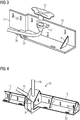
- Figure 2 shows a metal rail 6 belonging to a piping cover, which will be explained later.
- the metal rail 6 is below the support rod 5 of Figure 1 connectable to the central connection module 1.
- Its rear side has a section which is stepped in such a way that a piping 7 with a gradient, here consisting of a fresh water supply line 8 and a gray water line 9, is covered by the metal rail 6 in the region of the step.
- FIG 3 shows a metal rail 10, which to the compact, central connection module 1 of Figure 1 is connectable on the opposite side of the support rod 5.
- the metal rail 10 has a lateral tab 11 and a lower tab 36 which can be inserted into the metal housing 2 and which helps to fix it.
- the metal rail 10 has a general angular shape, a section of the gray water pipe 9 with a gray water inlet 12 being provided in the interior of the angle, said section being arranged below a wash basin 13, only an inner section of which is shown here.
- the metal rails 6, 10 of the Figures 2 and 3 has in common that they have stiffening angles 14 to increase stability.
- the illustrated metal rails 6, 10 can either be connected directly to the central connection module 1, for example by welding, or can be subsequently fixed to one another by screwing or gluing.
- the metal rails 6, 10 can also serve as supporting fasteners for wall connection as well as a support point for vanity units. Appropriate Bores or elongated holes 32 are therefore placed in angular surfaces of the metal rails 6, 10.
- Figure 4 shows an alternative embodiment of a central connection module 15, which is formed here in one piece with lateral metal rails 16 and 17.
- Handrails 18, 19 correspond in terms of their function to the handrails 4, 5 of the connection module 1 of Figure 1 ,
- the metal rails 16, 17, which emanate from the central connection module 15, are bent forward with their upper vertical section.
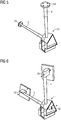
- FIGS. 5 and 6 show embodiments of how the structural unit comprising the central connection module 1, 33 and holding rods 4, 5 is to be fastened within the sanitary cell.
- a central connection module 33 does not have its own attachment option, while the support rods 4, 5 are equipped with connection flanges 34 at the end, via which attachment to a wall / ceiling of the sanitary cell can take place.
- the support rods 4, 5 are equipped with end pieces 35 which can be screwed onto the wall of the sanitary cell facing the rear of the connection module 1.
- the connection is therefore made exclusively via a single wall of the sanitary cell, starting from the central connection module 1 itself and two holding rods 4, 5.
- the central connection module 1 is dimensioned such that there is an intermediate space 26 between the paper dispenser 24 and the rear wall 25 of the central connection module 1, in which the gray water line 9 and possibly also the fresh water line 8 can be arranged.
- an upper side of the central connection module 1 is flush with an upper side of the washstand 29, while an underside of the central connection module 1 is flush with an underside of the piping cover 27.
- an underside of the cladding element 28 lies approximately at the height of the top of the piping cover 27.
- the piping cover 27 and the cladding element 28 have a constant height in the horizontal direction, so that geometric horizontal center planes of the piping cover 27 and the cladding element 28 are vertically offset from one another.
- the wash basin arrangement has a stepless underside, ie the undersides of the piping cover 27, a central connection module 35 and the cladding element 28 lie in one plane.
- the central connection module 35 now shows an upper side which projects in the form of a bead opposite the upper sides of the piping cover 27 and the washstand 29.
- a water tap 31 is provided, which is mounted on the central connection module 35, facing the wash basin 29, and is connected to the fresh water supply line 8.
- the bead mentioned acts like a natural overflow barrier.
- a resulting storage space above the paper dispenser module 24 can be provided as an integration option for a washing valve, to which the tap 31 belongs.
- the casing cover 27 is formed from an upper cover, the cover 20 from the Figures 7, 8 corresponds, and a metal rail as a lower cover as the rail 17.
- the wash basin 29 is a modification of the cover 20 and the cladding element 28 can be formed by the metal rail 16.
Description
Die Erfindung bezieht sich auf eine Sanitärzelle für ein Schienenfahrzeug, mit einer Waschtischanordnung, die einen Waschtisch aufweist, der mit einer Frischwasserzuleitung und einer Grauwasserleitung für ein Waschbecken ausgestattet ist, und die an einer Wand der Sanitärzelle befestigt ist. Bei einer solchen Sanitärzelle wird angestrebt, eine optisch ansprechende, strukturiert und aufgeräumt wirkende Ausbildung zu erzielen. Dazu ist es bekannt, beispielsweise komplette, sehr groß dimensionierte GFK-Wandelemente mit integriertem Waschtisch, Spiegelschränken und zusätzlichen "Ausbuchtungen" für eine Verrohrungsverortung zu fertigen.The invention relates to a sanitary cell for a rail vehicle, with a washstand arrangement which has a washstand which is equipped with a fresh water supply line and a gray water line for a wash basin, and which is fastened to a wall of the sanitary cell. With such a sanitary cell, the aim is to achieve an optically appealing, structured and tidy training. For this purpose, it is known, for example, to produce complete, very large-dimensioned GRP wall elements with an integrated washstand, mirror cabinets and additional “bulges” for a pipeline location.
Des Weiteren ist es ebenfalls bekannt, separate GFK-Module an einer Wabenwand zu fixieren. Dies erfordert jedoch, separate Zusatzverkleidungen für beispielsweise eine Abdeckung von Verrohrungen vorzusehen. Daraus ergibt sich eine sehr komplexe Auslegung der Waschtischanordnung, wie sie z. B. bei dem Fahrzeug "Desiro ML", DB Baureihe 460 verwirklicht ist.Furthermore, it is also known to fix separate GRP modules to a honeycomb wall. However, this requires providing separate additional cladding, for example for covering pipework. This results in a very complex interpretation of the washbasin arrangement, as z. B. is realized in the vehicle "Desiro ML", DB series 460.
Sanitärzellen für Schienenfahrzeuge sind ebenso aus der
Ausgehend hiervon liegt der Erfindung die Aufgabe zu Grunde, eine Sanitärzelle der eingangs genannten Art derart weiter zu entwickeln, dass sie kostengünstig zu fertigen ist und einen hohen Bewegungsfreiraum gerade im bodennahen Bereich bereitstellt.Proceeding from this, the invention is based on the object of further developing a sanitary cell of the type mentioned at the outset in such a way that it can be manufactured inexpensively and provides a high degree of freedom of movement, particularly in the area near the floor.
Diese Aufgabe wird bei der Nasszelle dadurch gelöst, dass die Waschtischanordnung ein zentrales, kompaktes Anbindungsmodul aufweist, dessen Rückseite in einer Höhe, die an eine gewünschte Lage des Waschbeckens angepasst ist, an der Wand befestigt ist, wobei an der einen Seite des zentralen Anbindungsmoduls ein Waschtisch mit darunter angeordnetem Verkleidungselement und an der anderen Seite des zentralen Anbindungsmoduls eine horizontal verlaufende Verrohrungsabdeckung für die Frischwasserzuleitung und/oder die Grauwasserleitung angeschlossen sind.This object is achieved in the wet room in that the washstand arrangement has a central, compact connection module, the back of which is attached to the wall at a height which is adapted to a desired position of the washbasin, with one on one side of the central connection module Vanity unit with a cladding element underneath and a horizontal piping cover on the other side of the central connection module for the fresh water supply and / or the gray water supply are connected.
Eine solche Waschtischanordnung ist kostengünstig zu fertigen, da an das zentrale, kompakte Anbindungsmodul weitere Komponenten, wie der Waschtisch mit dem darunter angeordneten Verkleidungselement und insbesondere die horizontal verlaufende Verrohrungsabdeckung anschließbar sind. Tragende Komponente der Waschtischanordnung ist somit das zentrale Anbindungsmodul, während die weiteren Komponenten wie die Verrohrungsabdeckung und der Waschtisch mit dem darunter angeordneten Verkleidungselement bedarfsweise zusätzliche Befestigungen zur Wand aufweisen. Die horizontal verlaufende Verrohrungsabdeckung bietet zudem den Vorteil, dass die Frischwasserzuleitung und/oder die Grauwasserleitung nicht, wie im Stand der Technik häufig anzutreffen, im Bodenbereich der Sanitärzelle angeordnet werden muss. Vielmehr können sowohl Frischwasserzuleitung als auch Grauwasserleitung für den Waschtisch außerhalb des bodennahen Bereichs verlaufen, nämlich beispielsweise innerhalb der Verrohrungsabdeckung oder auch zwischen der Verrohrungsabdeckung und dem benachbarten Sanitärzellenwandabschnitt.Such a washstand arrangement is inexpensive to manufacture, since further components, such as the washstand with the cladding element arranged underneath, and in particular the horizontally running piping cover, can be connected to the central, compact connection module. The supporting component of the washstand arrangement is thus the central connection module, while the further components such as the piping cover and the washstand with the cladding element arranged underneath have additional fastenings to the wall, if necessary. The horizontal piping cover also offers the advantage that the fresh water supply line and / or the gray water supply line does not have to be arranged in the floor area of the sanitary cell, as is often found in the prior art. Rather, both the fresh water supply line and the gray water supply line for the washstand can run outside the area near the floor, namely, for example, inside the piping cover or between the piping cover and the adjacent sanitary cell wall section.
Zur Unterstützung der Funktion des zentralen Anbindungsmoduls als Haupttrageinheit kann vorgesehen sein, dass von dem zentralen Anbindungsmodul eine vertikal und/oder eine horizontal verlaufende Haltestange, die auf der dem Waschtisch gegenüberliegenden Seite angeordnet ist, ausgehen, die zur Befestigung an einer Wand oder Decke der Sanitärzelle ausgebildet sind. Insbesondere wenn sowohl eine horizontal als auch eine vertikal verlaufende integrierte Haltestange an das zentrale Anbindungsmodul beispielsweise angeflanscht sind, ergibt sich eine hohe Tragfähigkeit des zentralen Anbindungsmoduls, das dann sowohl an der zugeordneten Sanitärzellenwand und über die beiden Haltestangen sowohl an der Decke als auch an einer weiteren Wand angebunden sein kann.To support the function of the central connection module as the main support unit, it can be provided that a vertical and / or a horizontally extending support rod, which is arranged on the side opposite the wash basin, extends from the central connection module and is intended for attachment to a wall or ceiling of the sanitary cell are trained. In particular, if both a horizontal and a vertical integrated support rod are flanged to the central connection module, for example, the central connection module has a high load-bearing capacity, which can then be attached to the associated sanitary cell wall and via the two support rods both on the ceiling and on another Wall can be tied.
Vorzugsweise ist in das zentrale Anbindungsmodul ein Funktionsmodul wie ein Papierspender integriert, und die dem Papierspender zugeordnete Seite des zentralen Anbindungsmoduls kann zu einer Rückseite der Waschtischanordnung in einem solchen Winkel verlaufen, dass die zugängliche Seite des Papierspenders einer Vorderseite eines in der Sanitärzelle der Waschtischanordnung benachbart angeordneten WC-Modul zugewandt ist, wobei zwischen dem Papierspender und der Rückseite der Waschtischanordnung ein Zwischenraum vorgesehen ist.A functional module such as a paper dispenser is preferably integrated into the central connection module, and the side of the central connection module assigned to the paper dispenser can run at an angle to a rear side of the washstand arrangement such that the accessible side of the paper dispenser is arranged adjacent to a front side in the sanitary cell of the washstand arrangement WC module is facing, with an intermediate space being provided between the paper dispenser and the rear of the washstand arrangement.
Diese Maßnahmen gewährleisten eine günstige Anordnung des Papierspenders für eine Benutzung von dem WC-Modul aus. Zudem gestattet der vorgesehene Zwischenraum zwischen der Rückseite der Waschtischanordnung und dem Papierspender eine Verlegung der Frischwasserzuleitung und/oder der Grauwasserleitung hinter dem Papierspender. Besagte Leitungen können dann von ihren vorgesehenen Anschlüssen an dem Waschtisch hinter dem Papierspender vorbei durch die/hinter der Verrohrungsabdeckung verlaufen.These measures ensure a favorable arrangement of the paper dispenser for use from the toilet module. In addition, the space provided between the rear of the washstand arrangement and the paper dispenser allows the fresh water supply line and / or the gray water line to be laid behind the paper dispenser. Said lines can then run from their intended connections past the washstand behind the paper dispenser through / behind the piping cover.
In einer Ausführungsform kann das zentrale Anbindungsmodul, der Waschtisch mit dem darunter angeordneten Verkleidungselement und die Verrohrungsabdeckung eine gemeinsame horizontale Mittelebene aufweisen. Eine besonders gleichmäßige Ausbildung der Waschtischanordnung ergibt sich dann, wenn zudem das zentrale Anbindungsmodul, der Waschtisch mit dem darunter angeordneten Verkleidungselement sowie die Verrohrungsabdeckung eine übereinstimmende Vertikalausdehnung aufweisen. Diese Ausführungsform zeichnet sich durch besondere einfache Fertigung aus.In one embodiment, the central connection module, the washstand with the cladding element arranged underneath and the piping cover can have a common horizontal central plane. A particularly uniform design of the washstand arrangement is obtained if the central connection module, the washstand with the cladding element arranged underneath and the piping cover also have a corresponding vertical dimension. This embodiment is characterized by a particularly simple manufacture.
Alternativ ist es auch möglich, dass eine horizontale Mittelebene der Verrohrungsabdeckung tiefer liegt als eine horizontale Mittelebene des Waschtischs mit darunter angeordnetem Verkleidungselement, wobei das zentrale Anbindungsmodul mit seiner Unterseite mit der Unterseite der Verrohrungsabdeckung und mit seiner Oberseite mit der Oberseite des Waschbeckens fluchtet. In diesem Fall zeigt die Einheit aus Verrohrungsabdeckung, zentralem Anbindungsmodul und Waschtisch mit darunter angeordnetem Verkleidungselement eine vertikale Stufe sowohl auf ihrer Oberseite als auch auf ihrer Unterseite. Der sich ergebende Freiraum unterhalb des Verkleidungselementes unter dem Waschtisch erhöht die Benutzungsfreundlichkeit desselben.Alternatively, it is also possible for a horizontal central plane of the piping cover to be lower than a horizontal central plane of the washstand with the cladding element arranged underneath, the central connection module having the underside of the piping cover and the top of the washbasin flees. In this case, the unit consisting of the piping cover, the central connection module and the washstand with the cladding element arranged underneath shows a vertical step on both its top and bottom. The resulting free space below the cladding element under the washstand increases the ease of use of the same.
In einer weiteren alternativen Ausführungsform der Erfindung kann die Verrohrungsabdeckung und der Waschtisch mit dem darunter angeordneten Verkleidungselement eine gemeinsame horizontale Mittelebene aufweisen und die Unterseiten der Verrohrungsabdeckung, des zentralen Anbindungsmoduls und des Verkleidungselementes unter dem Waschtisch in einer Ebene liegen, wobei das zentrale Anbindungsmodul gegenüber den Oberseite der Verrohrungsabdeckung und des Waschtischs nach oben vorsteht. Bei dieser Ausführungsform ergibt sich im Bereich des zentralen Anbindungselementes die Form eines umgedrehten "T". Der sich ergebende, nach oben vorstehende Wulst unterstützt eine saubere Trennung von Nass- und Trockenbereich und wirkt wie eine natürliche Überlaufbarriere. Bei dieser Ausführungsform kann zudem an dem zentralen Anbindungsmodul, dem Waschtisch zugewandt, ein Wasserhahn montiert sein, an dem die Frischwasserleitung angeschlossen ist.In a further alternative embodiment of the invention, the piping cover and the washstand with the cladding element arranged underneath can have a common horizontal central plane and the undersides of the piping cover, the central connection module and the cladding element lie below the washstand in one plane, the central connection module facing the top the piping cover and the washstand protrudes upwards. In this embodiment, the shape of an inverted "T" results in the region of the central connecting element. The resulting upward protruding bead supports a clean separation of wet and dry areas and acts as a natural overflow barrier. In this embodiment, a faucet to which the fresh water line is connected can also be mounted on the central connection module, facing the washstand.
Das zentrale Anbindungsmodul kann als Metallgehäuse ausgebildet sein und das unter dem Waschtisch angeordnete Verkleidungselement sowie die Verrohrungsabdeckung können eine nach oben und nach vorn offene Metallschiene aufweisen, die an der Wand der Sanitärzelle befestigbar ist. Bei dieser Ausführungsform sind das zentrale Anbindungsmodul sowie das Verkleidungselement und die Verrohrungsabdeckung gesonderte Bauteile, wobei beispielsweise sowohl das Verkleidungselement als auch die Verrohrungsabdeckung von der Seite in das zentrale Anbindungsmodul einsteckbar sein können.The central connection module can be designed as a metal housing and the cladding element arranged under the washstand and the piping cover can have a metal rail which is open at the top and to the front and can be fastened to the wall of the sanitary cell. In this embodiment, the central connection module and the cladding element and the piping cover are separate components, it being possible for example for both the cladding element and the piping cover to be insertable into the central connection module from the side.
Um beispielsweise Verrohrung abzudecken, können für die Metallschiene der Verrohrungsabdeckung und die Metallschiene des Verkleidungselements unterhalb des Waschtischs zusätzliche obere Abdeckungen vorgesehen sein, die an der jeweiligen Metallschiene befestigbar sind. Auf diese Weise sind sowohl das Verkleidungselement unterhalb des Waschtischs als auch die Verrohrungsabdeckung zusammengesetzt aus einer Metallschiene und einer zugehörigen Abdeckung.For example, to cover piping, the piping cover and the metal rail can be used for the metal rail of the cladding element, additional upper covers can be provided below the washstand, which can be fastened to the respective metal rail. In this way, both the cladding element below the washbasin and the piping cover are composed of a metal rail and an associated cover.
Alternativ zu der zuvor erläuterten dreiteiligen Ausbildung der Waschtischanordnung kann das zentrale Anbindungsmodul als Metallgehäuse ausgebildet sein und eine Baueinheit mit Metallschienen des Verkleidungselementes unterhalb des Waschtischs und/oder der Verrohrungsabdeckung bilden. Bei dieser Ausführungsform können ebenfalls für die Metallschiene der Verrohrungsabdeckung und die Metallschiene des Verkleidungselementes unterhalb des Waschtischs zusätzliche obere Abdeckungen vorgesehen sein, die an der jeweiligen Metallschiene befestigbar und abdichtbar sind.As an alternative to the three-part design of the washstand arrangement explained above, the central connection module can be designed as a metal housing and form a structural unit with metal rails of the cladding element below the washstand and / or the piping cover. In this embodiment, additional upper covers can also be provided for the metal rail of the piping cover and the metal rail of the cladding element below the washstand, which can be fastened and sealed on the respective metal rail.
Ausführungsbeispiele der Erfindung werden nachfolgend unter Bezugnahme auf die Zeichnungen noch näher erläutert. Dabei sind funktionsgleiche Komponenten mit denselben Bezugszeichen bezeichnet. Es zeigen:
- Figur 1
- eine perspektivische Ansicht eines zentralen Anbindungsmoduls für eine Wachtischanordnung in einer ersten Ausführungsform,
Figur 2- eine perspektivische Ansicht einer Metallschiene einer Verrohrungsabdeckung zum Anschluss an das zentrale Anbindungsmodul von
Figur 1 , Figur 3- eine perspektivische Ansicht einer Metallschiene eines Verkleidungselementes zum Anschluss an das zentrale Anbindungsmodul von
Figur 1 , Figur 4- eine perspektivische Ansicht eines zentralen Anbindungsmoduls einer Waschtischanordnung in einer zweiten Ausführungsform, mit seitlich davon ausgehenden Metallschienen einer Verrohrungsabdeckung und eines Verkleidungselementes,
- Figur 5
- eine perspektivische Ansicht eines anderen zentralen Anbindungsmoduls in Kombination mit Haltestangen,
- Figur 6
- eine perspektivische Ansicht des zentralen Anbindungsmoduls von
Figur 1 in Kombination mit Haltestangen, - Figur 7
- eine perspektivische Ansicht einer der Metallschienen von
Figur 4 - Figur 8
- eine Querschnittsansicht der Kombination aus Metallschiene und Abdeckung von
Figur 5 , Figur 9- eine Schnittansicht von oben auf das zentrale Anbindungsmodul von
Figur 1 , Figur 10- eine perspektivische Ansicht einer Waschtischanordnung in einer ersten Ausführungsform,
Figur 11- eine perspektivische Ansicht einer Waschtischanordnung in einer zweiten Ausführungsform und
- Figur 12
- eine perspektivische Ansicht einer Waschtischanordnung in einer dritten Ausführungsform.
- Figure 1
- 1 shows a perspective view of a central connection module for a watch table arrangement in a first embodiment,
- Figure 2
- a perspective view of a metal rail of a piping cover for connection to the central connection module of
Figure 1 . - Figure 3
- a perspective view of a metal rail of a cladding element for connection to the central connection module of
Figure 1 . - Figure 4
- 2 shows a perspective view of a central connection module of a washstand arrangement in a second embodiment, with metal rails of a piping cover and a cladding element extending laterally therefrom,
- Figure 5
- a perspective view of another central connection module in combination with handrails,
- Figure 6
- a perspective view of the central connection module of
Figure 1 in combination with handrails, - Figure 7
- a perspective view of one of the metal rails of
Figure 4 in combination with a cover, - Figure 8
- a cross-sectional view of the combination of metal rail and cover of
Figure 5 . - Figure 9
- a sectional view from above of the central connection module of
Figure 1 . - Figure 10
- 2 shows a perspective view of a washstand arrangement in a first embodiment,
- Figure 11
- a perspective view of a washstand arrangement in a second embodiment and
- Figure 12
- a perspective view of a washstand arrangement in a third embodiment.
Von dem Metallgehäuse 2 gehen eine vertikal verlaufende Haltestange 4 sowie eine horizontal verlaufende Haltestange 5 aus, die beispielsweise per Schraubbefestigung an dem Metallgehäuse 2 angebracht sind.A
Das Metallgehäuse 2 ist zur Befestigung an einer Wand einer Sanitärzelle ausgeführtThe
Eine Rückseite des Metallgehäuses 2 liegt im eingebauten Zustand an der Wand der Sanitärzelle an und weist Langlöcher 32 auf, so dass eine Verschraubung mit der Sanitärzellenwand ermöglicht ist. Das zentrale Anbindungsmodul 1 kann somit über das Metallgehäuse 2 selbst sowie über die Haltestangen 4 und 5 gegenüber der Sanitärzelle fixiert werden, wobei die horizontale Haltestange 5 an einer weiteren Wand der Sanitärzelle und die vertikale Haltestange 4 an einer Decke der Sanitärzelle befestigt sein kann.When installed, a rear side of the
Auch
Den Metallschienen 6, 10 der
Aus
Die Metallschienen 16, 17, die von dem zentralen Anbindungsmodul 15 ausgehen, sind mit ihrem oberen vertikalen Abschnitt nach vorn abgekantet.The metal rails 16, 17, which emanate from the
Die
Der Zweck der anhand von
Aus
Dabei ist das zentrale Anbindungsmodul 1 derart bemessen, dass sich zwischen dem Papierspender 24 und der Rückwand 25 des zentralen Anbindungsmoduls 1 ein Zwischenraum 26 ergibt, in dem die Grauwasserleitung 9 und ggf. auch die Frischwasserleitung 8 angeordnet werden kann.The central connection module 1 is dimensioned such that there is an
Aus
Bei der Ausführungsform einer Waschtischanordnung nach
Aus
Bei den Ausführungsformen für eine Waschtischanordnung nach den
Bei der Ausführungsform nach
In den
Claims (12)
- Bathroom pod for a rail vehicle, having a washbasin arrangement comprising a washbasin (29) equipped with a fresh-water supply line (8) and a grey-water line (9) for a basin (13), and wherein the washbasin arrangement is fastened on a wall of the bathroom pod,
characterized in that
the washbasin arrangement has a central, compact attachment module (1), of which the rear side is fastened on the wall of the bathroom pod at a height adapted to a desired position of the basin (13), wherein the washbasin (29), with a panelling element (28) arranged therebeneath, is connected on the one side of the central attachment module (1), and a horizontally running pipework cover (27) for the fresh-water supply line (8) and/or the grey-water line (9) is connected on the other side of the central attachment module (1). - Bathroom pod according to Claim 1,
characterized in that
an integrated, vertically running (4) and/or horizontally running (5) retaining bar (5) extend/extends from the central attachment module (1), each bar being arranged on the side located opposite the washbasin (29) and being designed for fastening on a wall or ceiling of the bathroom pod. - Bathroom pod according to either of Claims 1 and 2,
characterized in that
a functional module (24) is integrated in the central attachment module (1), and that side of the central attachment module (1) which is assigned to the functional module (24) runs at such an angle to a rear side of the washbasin arrangement that the accessible side of the functional module (24) is directed towards a front side of a WC module (30), which is arranged alongside the washbasin arrangement in the bathroom pod,
wherein an intermediate space (26) is provided between the functional module (24) and the rear side of the washbasin arrangement. - Bathroom pod according to one of Claims 1 to 3,
characterized in that
the central attachment module (1), the washbasin (29), with the panelling element (28) arranged therebeneath, and the pipework cover (27) together form a seamless front contour which is curved in the forward direction in the region of the washbasin (29). - Bathroom pod according to one of Claims 1 to 4,
characterized in that
the central attachment module (1), the washbasin (29), with the panelling element (28) arranged therebeneath, and the pipework cover (27) have a common horizontal centre plane. - Bathroom pod according to one of Claims 1 to 4,
characterized in that
a horizontal centre plane of the pipework cover (27) is located at a lower level than a horizontal centre plane of the washbasin (29), with the panelling element (28) arranged therebeneath, wherein the central attachment module (1) has its underside aligned with the underside of the pipework cover (27) and its upper side aligned with the upper side of the basin (13). - Bathroom pod according to one of Claims 1 to 4,
characterized in that
the pipework cover (27) and the washbasin (29), with the panelling element (28) arranged therebeneath, have a common horizontal centre plane, and the undersides of the pipework cover (27), of the central attachment module (1) and of the panelling element (28) are located in a single plane beneath the washbasin (29), wherein the central attachment module (1) projects upwards in relation to the upper sides of the pipework cover (27) and of the washbasin (29). - Bathroom pod according to Claim 7,
characterized in that
a tap (31), to which the fresh-water supply line (8) is connected, is mounted on the central attachment module (1), facing the washbasin (29). - Bathroom pod according to one of Claims 1 to 8,
characterized in that
the central attachment module (1) is designed in the form of a metal housing, and the panelling element (28), which is arranged beneath the washbasin (29), and also the pipework cover (27) have a metal rail (6, 10) which is open in the upward direction and towards the front and can be fastened on the wall of the bathroom pod. - Bathroom pod according to Claim 9,
characterized in that
covers (20) are provided for the metal rail (6) of the pipework cover (27) and the metal rail (10) of the panelling element (28) beneath the washbasin (29), it being possible for said covers to be fastened on the respective metal rail (6, 10). - Bathroom pod according to one of Claims 1 to 8,
characterized in that
the central attachment module (1) is designed in the form of a metal housing (2) and forms a structural unit with metal rails (6, 10) of the panelling element (28) beneath the washbasin (29) and/or of the pipework cover (27) . - Bathroom pod according to Claim 11,
characterized in that
covers (20) are provided for the metal rail (6) of the pipework cover (27) and the metal rail (10) of the panelling element (28) beneath the washbasin (29), it being possible for said covers to be fastened and sealed on the respective metal rail (6, 10).
Priority Applications (1)
| Application Number | Priority Date | Filing Date | Title |
|---|---|---|---|
| PL14761820T PL3033258T3 (en) | 2013-09-27 | 2014-08-29 | Sanitary cell for a rail vehicle |
Applications Claiming Priority (2)
| Application Number | Priority Date | Filing Date | Title |
|---|---|---|---|
| DE102013219646.6A DE102013219646B3 (en) | 2013-09-27 | 2013-09-27 | Sanitary cell for a rail vehicle |
| PCT/EP2014/068358 WO2015043875A1 (en) | 2013-09-27 | 2014-08-29 | Sanitary cell for a rail vehicle |
Publications (2)
| Publication Number | Publication Date |
|---|---|
| EP3033258A1 EP3033258A1 (en) | 2016-06-22 |
| EP3033258B1 true EP3033258B1 (en) | 2020-02-05 |
Family
ID=51518757
Family Applications (1)
| Application Number | Title | Priority Date | Filing Date |
|---|---|---|---|
| EP14761820.1A Active EP3033258B1 (en) | 2013-09-27 | 2014-08-29 | Sanitary cell for a rail vehicle |
Country Status (9)
| Country | Link |
|---|---|
| EP (1) | EP3033258B1 (en) |
| CN (1) | CN205951980U (en) |
| DE (1) | DE102013219646B3 (en) |
| DK (1) | DK3033258T3 (en) |
| ES (1) | ES2784161T3 (en) |
| PL (1) | PL3033258T3 (en) |
| PT (1) | PT3033258T (en) |
| RU (1) | RU170407U1 (en) |
| WO (1) | WO2015043875A1 (en) |
Families Citing this family (3)
| Publication number | Priority date | Publication date | Assignee | Title |
|---|---|---|---|---|
| DE102015210475A1 (en) * | 2015-06-09 | 2016-12-15 | Siemens Aktiengesellschaft | Wet cell for a rail vehicle |
| DE102016205376A1 (en) | 2016-03-31 | 2017-10-05 | Siemens Aktiengesellschaft | Wet cell of a rail vehicle of passenger traffic |
| CN107554541B (en) * | 2017-08-24 | 2019-07-30 | 宁波中车时代传感技术有限公司 | Vehicle ash water recycling handles reuse means |
Family Cites Families (3)
| Publication number | Priority date | Publication date | Assignee | Title |
|---|---|---|---|---|
| DE2446954A1 (en) * | 1974-10-02 | 1976-04-08 | Messerschmitt Boelkow Blohm | External service connected railway toilet compartment - is prefabricated cell with integral fittings and insertable as unit |
| FR2661934B1 (en) * | 1990-05-11 | 1993-06-04 | Cocoon Sa | MODULAR ACCOMMODATION UNIT. |
| EP0612296B1 (en) * | 1992-09-19 | 1996-12-27 | PFA PARTNER FÜR FAHRZEUG-AUSSTATTUNG GmbH | Room, cabin or compartment, in particular for hotel trains |
-
2013
- 2013-09-27 DE DE102013219646.6A patent/DE102013219646B3/en not_active Expired - Fee Related
-
2014
- 2014-08-29 ES ES14761820T patent/ES2784161T3/en active Active
- 2014-08-29 DK DK14761820.1T patent/DK3033258T3/en active
- 2014-08-29 WO PCT/EP2014/068358 patent/WO2015043875A1/en active Application Filing
- 2014-08-29 CN CN201490001082.5U patent/CN205951980U/en active Active
- 2014-08-29 RU RU2016116489U patent/RU170407U1/en active
- 2014-08-29 EP EP14761820.1A patent/EP3033258B1/en active Active
- 2014-08-29 PT PT147618201T patent/PT3033258T/en unknown
- 2014-08-29 PL PL14761820T patent/PL3033258T3/en unknown
Non-Patent Citations (1)
| Title |
|---|
| None * |
Also Published As
| Publication number | Publication date |
|---|---|
| CN205951980U (en) | 2017-02-15 |
| PT3033258T (en) | 2020-03-27 |
| WO2015043875A1 (en) | 2015-04-02 |
| RU170407U1 (en) | 2017-04-24 |
| ES2784161T3 (en) | 2020-09-22 |
| DE102013219646B3 (en) | 2015-01-08 |
| DK3033258T3 (en) | 2020-04-27 |
| EP3033258A1 (en) | 2016-06-22 |
| PL3033258T3 (en) | 2020-07-27 |
Similar Documents
| Publication | Publication Date | Title |
|---|---|---|
| EP2159336B1 (en) | Use of a floor drain | |
| EP3746607B1 (en) | System comprising a connecting device and a sanitary appliance | |
| EP3033258B1 (en) | Sanitary cell for a rail vehicle | |
| DE202010017544U1 (en) | Shower drain arrangement for a shower place | |
| EP0386559B1 (en) | Shower partition | |
| DE2937624A1 (en) | Prefab. bathroom or toilet cell frame - comprises bent sheet metal plate of half room height, providing partition | |
| EP1162907B1 (en) | Method for installing a tub support and tub shell mounted in a tub support | |
| EP2119837B1 (en) | Drain fittings for wash or drainage basin | |
| DE69727166T2 (en) | Precast element for the effective coupling of an installation block to a liquid supply and disposal system | |
| DE10204683B4 (en) | pool | |
| DE3103511C2 (en) | Sanitary appliance which is arranged on a turntable which can be rotated about its vertical central axis | |
| DE202006017203U1 (en) | lavatory | |
| EP1223253B1 (en) | Sanitary arrangement | |
| DE19510228A1 (en) | Fastening device of a cistern | |
| EP2808458A1 (en) | Water drainage device for a shower and shower floor element | |
| DE202021104879U1 (en) | Smart toilet | |
| CH693932A5 (en) | Facility with sanitary and / or Kuechenkomponenten. | |
| DE7237302U (en) | SANITARY CELL | |
| DE19747935A1 (en) | Shower cabin | |
| DE2314552C3 (en) | Washing or rinsing block that can be set up anywhere in the room | |
| DE2629810A1 (en) | CONSTRUCTION ELEMENT TO BE USED IN BUILDING CONSTRUCTION AS PREFABRICATED UNIT | |
| DE7408108U (en) | Wash stand, sink or similar piece of furniture with hot water storage tank or tank battery | |
| DE7926438U1 (en) | CELL ELEMENT FOR BATHING, WASHING, TOILET ROOMS AND THE LIKE | |
| DE202011102926U1 (en) | Shower floor element | |
| EP1445554A1 (en) | Heater |
Legal Events
| Date | Code | Title | Description |
|---|---|---|---|
| PUAI | Public reference made under article 153(3) epc to a published international application that has entered the european phase |
Free format text: ORIGINAL CODE: 0009012 |
|
| 17P | Request for examination filed |
Effective date: 20160309 |
|
| AK | Designated contracting states |
Kind code of ref document: A1 Designated state(s): AL AT BE BG CH CY CZ DE DK EE ES FI FR GB GR HR HU IE IS IT LI LT LU LV MC MK MT NL NO PL PT RO RS SE SI SK SM TR |
|
| AX | Request for extension of the european patent |
Extension state: BA ME |
|
| DAX | Request for extension of the european patent (deleted) | ||
| RAP1 | Party data changed (applicant data changed or rights of an application transferred) |
Owner name: SIEMENS AKTIENGESELLSCHAFT |
|
| RAP1 | Party data changed (applicant data changed or rights of an application transferred) |
Owner name: SIEMENS MOBILITY GMBH |
|
| STAA | Information on the status of an ep patent application or granted ep patent |
Free format text: STATUS: EXAMINATION IS IN PROGRESS |
|
| 17Q | First examination report despatched |
Effective date: 20190515 |
|
| GRAP | Despatch of communication of intention to grant a patent |
Free format text: ORIGINAL CODE: EPIDOSNIGR1 |
|
| STAA | Information on the status of an ep patent application or granted ep patent |
Free format text: STATUS: GRANT OF PATENT IS INTENDED |
|
| INTG | Intention to grant announced |
Effective date: 20190927 |
|
| GRAS | Grant fee paid |
Free format text: ORIGINAL CODE: EPIDOSNIGR3 |
|
| GRAA | (expected) grant |
Free format text: ORIGINAL CODE: 0009210 |
|
| STAA | Information on the status of an ep patent application or granted ep patent |
Free format text: STATUS: THE PATENT HAS BEEN GRANTED |
|
| AK | Designated contracting states |
Kind code of ref document: B1 Designated state(s): AL AT BE BG CH CY CZ DE DK EE ES FI FR GB GR HR HU IE IS IT LI LT LU LV MC MK MT NL NO PL PT RO RS SE SI SK SM TR |
|
| REG | Reference to a national code |
Ref country code: GB Ref legal event code: FG4D Free format text: NOT ENGLISH |
|
| REG | Reference to a national code |
Ref country code: AT Ref legal event code: REF Ref document number: 1229695 Country of ref document: AT Kind code of ref document: T Effective date: 20200215 |
|
| REG | Reference to a national code |
Ref country code: DE Ref legal event code: R096 Ref document number: 502014013560 Country of ref document: DE |
|
| REG | Reference to a national code |
Ref country code: IE Ref legal event code: FG4D Free format text: LANGUAGE OF EP DOCUMENT: GERMAN |
|
| REG | Reference to a national code |
Ref country code: CH Ref legal event code: NV Representative=s name: SIEMENS SCHWEIZ AG, CH |
|
| REG | Reference to a national code |
Ref country code: PT Ref legal event code: SC4A Ref document number: 3033258 Country of ref document: PT Date of ref document: 20200327 Kind code of ref document: T Free format text: AVAILABILITY OF NATIONAL TRANSLATION Effective date: 20200318 |
|
| REG | Reference to a national code |
Ref country code: CH Ref legal event code: EP |
|
| REG | Reference to a national code |
Ref country code: NL Ref legal event code: FP |
|
| REG | Reference to a national code |
Ref country code: DK Ref legal event code: T3 Effective date: 20200425 |
|
| PG25 | Lapsed in a contracting state [announced via postgrant information from national office to epo] |
Ref country code: RS Free format text: LAPSE BECAUSE OF FAILURE TO SUBMIT A TRANSLATION OF THE DESCRIPTION OR TO PAY THE FEE WITHIN THE PRESCRIBED TIME-LIMIT Effective date: 20200205 Ref country code: FI Free format text: LAPSE BECAUSE OF FAILURE TO SUBMIT A TRANSLATION OF THE DESCRIPTION OR TO PAY THE FEE WITHIN THE PRESCRIBED TIME-LIMIT Effective date: 20200205 Ref country code: NO Free format text: LAPSE BECAUSE OF FAILURE TO SUBMIT A TRANSLATION OF THE DESCRIPTION OR TO PAY THE FEE WITHIN THE PRESCRIBED TIME-LIMIT Effective date: 20200505 |
|
| REG | Reference to a national code |
Ref country code: LT Ref legal event code: MG4D |
|
| PG25 | Lapsed in a contracting state [announced via postgrant information from national office to epo] |
Ref country code: IS Free format text: LAPSE BECAUSE OF FAILURE TO SUBMIT A TRANSLATION OF THE DESCRIPTION OR TO PAY THE FEE WITHIN THE PRESCRIBED TIME-LIMIT Effective date: 20200605 Ref country code: GR Free format text: LAPSE BECAUSE OF FAILURE TO SUBMIT A TRANSLATION OF THE DESCRIPTION OR TO PAY THE FEE WITHIN THE PRESCRIBED TIME-LIMIT Effective date: 20200506 Ref country code: BG Free format text: LAPSE BECAUSE OF FAILURE TO SUBMIT A TRANSLATION OF THE DESCRIPTION OR TO PAY THE FEE WITHIN THE PRESCRIBED TIME-LIMIT Effective date: 20200505 Ref country code: HR Free format text: LAPSE BECAUSE OF FAILURE TO SUBMIT A TRANSLATION OF THE DESCRIPTION OR TO PAY THE FEE WITHIN THE PRESCRIBED TIME-LIMIT Effective date: 20200205 Ref country code: LV Free format text: LAPSE BECAUSE OF FAILURE TO SUBMIT A TRANSLATION OF THE DESCRIPTION OR TO PAY THE FEE WITHIN THE PRESCRIBED TIME-LIMIT Effective date: 20200205 Ref country code: SE Free format text: LAPSE BECAUSE OF FAILURE TO SUBMIT A TRANSLATION OF THE DESCRIPTION OR TO PAY THE FEE WITHIN THE PRESCRIBED TIME-LIMIT Effective date: 20200205 |
|
| REG | Reference to a national code |
Ref country code: ES Ref legal event code: FG2A Ref document number: 2784161 Country of ref document: ES Kind code of ref document: T3 Effective date: 20200922 |
|
| PG25 | Lapsed in a contracting state [announced via postgrant information from national office to epo] |
Ref country code: SM Free format text: LAPSE BECAUSE OF FAILURE TO SUBMIT A TRANSLATION OF THE DESCRIPTION OR TO PAY THE FEE WITHIN THE PRESCRIBED TIME-LIMIT Effective date: 20200205 Ref country code: EE Free format text: LAPSE BECAUSE OF FAILURE TO SUBMIT A TRANSLATION OF THE DESCRIPTION OR TO PAY THE FEE WITHIN THE PRESCRIBED TIME-LIMIT Effective date: 20200205 Ref country code: RO Free format text: LAPSE BECAUSE OF FAILURE TO SUBMIT A TRANSLATION OF THE DESCRIPTION OR TO PAY THE FEE WITHIN THE PRESCRIBED TIME-LIMIT Effective date: 20200205 Ref country code: LT Free format text: LAPSE BECAUSE OF FAILURE TO SUBMIT A TRANSLATION OF THE DESCRIPTION OR TO PAY THE FEE WITHIN THE PRESCRIBED TIME-LIMIT Effective date: 20200205 Ref country code: SK Free format text: LAPSE BECAUSE OF FAILURE TO SUBMIT A TRANSLATION OF THE DESCRIPTION OR TO PAY THE FEE WITHIN THE PRESCRIBED TIME-LIMIT Effective date: 20200205 |
|
| REG | Reference to a national code |
Ref country code: DE Ref legal event code: R097 Ref document number: 502014013560 Country of ref document: DE |
|
| PLBE | No opposition filed within time limit |
Free format text: ORIGINAL CODE: 0009261 |
|
| STAA | Information on the status of an ep patent application or granted ep patent |
Free format text: STATUS: NO OPPOSITION FILED WITHIN TIME LIMIT |
|
| 26N | No opposition filed |
Effective date: 20201106 |
|
| PG25 | Lapsed in a contracting state [announced via postgrant information from national office to epo] |
Ref country code: SI Free format text: LAPSE BECAUSE OF FAILURE TO SUBMIT A TRANSLATION OF THE DESCRIPTION OR TO PAY THE FEE WITHIN THE PRESCRIBED TIME-LIMIT Effective date: 20200205 |
|
| PG25 | Lapsed in a contracting state [announced via postgrant information from national office to epo] |
Ref country code: MC Free format text: LAPSE BECAUSE OF FAILURE TO SUBMIT A TRANSLATION OF THE DESCRIPTION OR TO PAY THE FEE WITHIN THE PRESCRIBED TIME-LIMIT Effective date: 20200205 |
|
| PG25 | Lapsed in a contracting state [announced via postgrant information from national office to epo] |
Ref country code: LU Free format text: LAPSE BECAUSE OF NON-PAYMENT OF DUE FEES Effective date: 20200829 |
|
| PG25 | Lapsed in a contracting state [announced via postgrant information from national office to epo] |
Ref country code: IE Free format text: LAPSE BECAUSE OF NON-PAYMENT OF DUE FEES Effective date: 20200829 |
|
| PG25 | Lapsed in a contracting state [announced via postgrant information from national office to epo] |
Ref country code: MT Free format text: LAPSE BECAUSE OF FAILURE TO SUBMIT A TRANSLATION OF THE DESCRIPTION OR TO PAY THE FEE WITHIN THE PRESCRIBED TIME-LIMIT Effective date: 20200205 Ref country code: CY Free format text: LAPSE BECAUSE OF FAILURE TO SUBMIT A TRANSLATION OF THE DESCRIPTION OR TO PAY THE FEE WITHIN THE PRESCRIBED TIME-LIMIT Effective date: 20200205 |
|
| PG25 | Lapsed in a contracting state [announced via postgrant information from national office to epo] |
Ref country code: MK Free format text: LAPSE BECAUSE OF FAILURE TO SUBMIT A TRANSLATION OF THE DESCRIPTION OR TO PAY THE FEE WITHIN THE PRESCRIBED TIME-LIMIT Effective date: 20200205 Ref country code: AL Free format text: LAPSE BECAUSE OF FAILURE TO SUBMIT A TRANSLATION OF THE DESCRIPTION OR TO PAY THE FEE WITHIN THE PRESCRIBED TIME-LIMIT Effective date: 20200205 |
|
| PGFP | Annual fee paid to national office [announced via postgrant information from national office to epo] |
Ref country code: NL Payment date: 20220810 Year of fee payment: 9 |
|
| PGFP | Annual fee paid to national office [announced via postgrant information from national office to epo] |
Ref country code: TR Payment date: 20220826 Year of fee payment: 9 Ref country code: PT Payment date: 20220725 Year of fee payment: 9 Ref country code: DK Payment date: 20220824 Year of fee payment: 9 |
|
| PGFP | Annual fee paid to national office [announced via postgrant information from national office to epo] |
Ref country code: BE Payment date: 20220817 Year of fee payment: 9 |
|
| PGFP | Annual fee paid to national office [announced via postgrant information from national office to epo] |
Ref country code: IT Payment date: 20230828 Year of fee payment: 10 Ref country code: GB Payment date: 20230904 Year of fee payment: 10 Ref country code: CZ Payment date: 20230821 Year of fee payment: 10 Ref country code: AT Payment date: 20230713 Year of fee payment: 10 |
|
| PGFP | Annual fee paid to national office [announced via postgrant information from national office to epo] |
Ref country code: PL Payment date: 20230817 Year of fee payment: 10 Ref country code: FR Payment date: 20230822 Year of fee payment: 10 |
|
| PGFP | Annual fee paid to national office [announced via postgrant information from national office to epo] |
Ref country code: ES Payment date: 20231124 Year of fee payment: 10 |
|
| PGFP | Annual fee paid to national office [announced via postgrant information from national office to epo] |
Ref country code: DE Payment date: 20231019 Year of fee payment: 10 Ref country code: CH Payment date: 20231113 Year of fee payment: 10 |
|
| REG | Reference to a national code |
Ref country code: DK Ref legal event code: EBP Effective date: 20230831 |
|
| REG | Reference to a national code |
Ref country code: NL Ref legal event code: MM Effective date: 20230901 |