EP3031631A1 - Fahrzeugluftreifen aufweisend eine notlaufschicht - Google Patents
Fahrzeugluftreifen aufweisend eine notlaufschicht Download PDFInfo
- Publication number
- EP3031631A1 EP3031631A1 EP15184377.8A EP15184377A EP3031631A1 EP 3031631 A1 EP3031631 A1 EP 3031631A1 EP 15184377 A EP15184377 A EP 15184377A EP 3031631 A1 EP3031631 A1 EP 3031631A1
- Authority
- EP
- European Patent Office
- Prior art keywords
- vehicle tire
- run
- pneumatic vehicle
- layer
- rim
- Prior art date
- Legal status (The legal status is an assumption and is not a legal conclusion. Google has not performed a legal analysis and makes no representation as to the accuracy of the status listed.)
- Granted
Links
Images
Classifications
-
- B—PERFORMING OPERATIONS; TRANSPORTING
- B60—VEHICLES IN GENERAL
- B60C—VEHICLE TYRES; TYRE INFLATION; TYRE CHANGING; CONNECTING VALVES TO INFLATABLE ELASTIC BODIES IN GENERAL; DEVICES OR ARRANGEMENTS RELATED TO TYRES
- B60C17/00—Tyres characterised by means enabling restricted operation in damaged or deflated condition; Accessories therefor
- B60C17/10—Internal lubrication
-
- B—PERFORMING OPERATIONS; TRANSPORTING
- B60—VEHICLES IN GENERAL
- B60C—VEHICLE TYRES; TYRE INFLATION; TYRE CHANGING; CONNECTING VALVES TO INFLATABLE ELASTIC BODIES IN GENERAL; DEVICES OR ARRANGEMENTS RELATED TO TYRES
- B60C17/00—Tyres characterised by means enabling restricted operation in damaged or deflated condition; Accessories therefor
- B60C17/04—Tyres characterised by means enabling restricted operation in damaged or deflated condition; Accessories therefor utilising additional non-inflatable supports which become load-supporting in emergency
- B60C17/06—Tyres characterised by means enabling restricted operation in damaged or deflated condition; Accessories therefor utilising additional non-inflatable supports which become load-supporting in emergency resilient
-
- B—PERFORMING OPERATIONS; TRANSPORTING
- B60—VEHICLES IN GENERAL
- B60C—VEHICLE TYRES; TYRE INFLATION; TYRE CHANGING; CONNECTING VALVES TO INFLATABLE ELASTIC BODIES IN GENERAL; DEVICES OR ARRANGEMENTS RELATED TO TYRES
- B60C17/00—Tyres characterised by means enabling restricted operation in damaged or deflated condition; Accessories therefor
- B60C2017/0081—Tyres characterised by means enabling restricted operation in damaged or deflated condition; Accessories therefor comprising special reinforcing means in the crown area
Definitions
- the invention relates to a pneumatic vehicle tire for a wheel system having a rim with rim flanges, mounted on the rim pneumatic vehicle tire and mounted on the rim axially within the pneumatic vehicle tire support device whose radial height exceeds the radial height of the rim flanges, wherein in emergency operation, the support device radially outside the radial height of the rim flanges with the pneumatic vehicle tire comes in contact and load, the vehicle pneumatic tire side walls, beads with bead cores, a carcass, which extends from the zenith of the vehicle pneumatic tire on the side walls to the bead areas and is anchored there by wrapping tensile bead cores, a radial Outside the carcass located tread belt package and arranged radially inside the carcass inner layer. Furthermore, the invention relates to a wheel system comprising a support device and such a pneumatic vehicle tire.
- Such a pneumatic vehicle tire is mounted on the vehicle usually airtight on a rim. By an overpressure in the wheel system of the pneumatic vehicle tire is kept in shape. In the event of a breakdown of such a pneumatic vehicle tire usually escapes air and the pneumatic vehicle tire can no longer or not sufficiently be kept in shape. In an emergency operation, ie a ride with too little or no pressure in the wheel system is done by flexing and / or friction strong heating of the pneumatic vehicle tire, which makes further driving of the vehicle difficult or impossible and may result in the destruction of the pneumatic vehicle tire. In the event of a breakdown, for example a civilian or a civilian However, in the event of a military breakdown, it may be necessary for the vehicle to be moved away from the place of the breakdown in emergency operation.
- the pneumatic tire and / or the supporting device is destroyed by mechanical abrasion and / or temperature due to the friction between the pneumatic vehicle tire and the supporting device during continuous emergency operation.
- this is quickly consumed and concentrated in emergency not at the place of great friction but distributed throughout the wheel system.
- the filling of the grease complicates the assembly of the pneumatic vehicle tire on the rim.
- the invention has for its object to provide a pneumatic vehicle tire for a wheel system with support device available, which is characterized by an increased mileage of the wheel system in emergency and by a simpler installation.
- the pneumatic vehicle tire has a run-flat layer of elastomeric material radially inside the inner layer in that the elastomeric material contains at least one wax and / or at least one fat, wherein the elastomeric material has a higher weight fraction (% by weight) of wax and / or having fat than the Karkassgummtechnik and by the run-flat layer is arranged so that contact the run flat layer and the support device in the emergency and that the load is absorbed by the support device at least partially in the region of the contact surface between runflat layer and support device.
- the pneumatic vehicle tire is distinguished by the fact that in emergency operation the wax and / or the grease reduce the friction between the pneumatic vehicle tire and the support device and thus the running performance of the wheel system in emergency operation is increased.
- the run-flat layer is arranged so that in the emergency run the load is absorbed by the support device at least partially in the region of the contact surface of run-flat layer and support device.
- Supporting device and run-flat layer may be initially separated by one or more further layers in the radial direction, which are destroyed in the emergency on the friction surface, whereby the emergency running layer comes into direct contact with the support device. Run-flat layer and supporting device are pressed against each other.
- the elastomeric material of the run-flat layer is formed by the addition of grease and / or wax so that it unfolds by friction associated with the emergency loads such as increased pressure, elevated temperature and / or friction friction-reducing effect at least at the contact surface to the support device.
- the friction-reducing effect thus takes place at the location of high friction, whereby the mechanical stress is reliably reduced there and also associated with the friction heat generation is reduced. As a result, the destruction of the pneumatic vehicle tire and / or the support device is delayed. The mileage of a wheel system having such a pneumatic vehicle tire is thus increased in emergency operation.
- the emergency running layer is a part of the pneumatic vehicle tire, whereby the pneumatic vehicle tire is easy to assemble. An additional work step, such as the filling of fat, is not necessary.
- the elastomeric material of the run-flat layer changes in the radial direction, preferably when the proportion by weight (% by weight) of fat and / or wax of the elastomeric material changes in the radial direction.
- the abrasion behavior of the run-flat layer can be set specifically. The friction can thus be reliably reduced over a longer period of time and the destruction of the pneumatic vehicle tire and / or the support element can be delayed. The mileage of such a pneumatic vehicle tire in emergency is thus increased.
- the run-flat layer has one or more depots which contain a substance having a friction-reducing effect, in particular a substance having a friction-reducing action comprising at least one wax and / or at least one fat.
- a depot is a cavity in the elastomeric material, which contains the substance with friction-reducing effect.
- the wall of the depot may be formed of a different material to the elastomeric material. Depots can have the same or a different geometry and contain the same or different substances.
- a layer is arranged which is largely impermeable to the wax and / or the fat of the elastomeric material of the run-flat layer. This can be a Spread of wax and / or grease from the run-flat layer to other areas of the tire can be avoided or reduced.
- the layer connects radially to the run-flat layer, in particular if the layer is the inner layer.
- the layer covers the entire inside of the pneumatic vehicle tire, but at least the radially outer surface of the emergency running layer.
- the layer is applied to the surface of the run-flat layer, in particular over the entire surface of the run-flat layer.
- the run-flat layer has a specific thermal conductivity which is greater than the specific thermal conductivity of the inner layer and / or which is greater than the specific thermal conductivity of the carcass gumming, in particular under emergency running conditions. As a result, a rapid dissipation of heat generated in emergency is guaranteed, whereby the mileage is increased.
- the inner layer mixture is based on a halobutyl rubber or an inner layer mixture for tubular tires.
- the run-flat layer is arranged such that the axial extent of the run-flat layer corresponds at least to the axial extent of the load-bearing surface of the support device in the emergency run.
- the friction-reducing effect can develop in emergency on the entire load-receiving surface of the support device.
- the radially inner surface of the run-flat layer has a profile.
- the exit surface for the wax and / or fat is increased and improves the handling of the wheel system.
- the profile has profile grooves in the circumferential direction.
- the radially outer surface of the run-flat layer has a profile and the surface of the radially next layer adjacent thereto has a profile of the same shape.
- the contact surface between the layers is increased, whereby the cohesion of the layers is improved by the increased surface, which is available for a compound by vulcanization and / or an elastic adhesive bond, compared to a non-profiled surface.
- a profiling is also advantageous for coping with forces occurring in emergency operation, such as lateral and / or torsional forces.
- the profile has profile grooves in the circumferential direction.
- An increase in mileage in emergency operation is advantageous for commercial vehicle tires.
- the reliable increase in mileage in emergency is advantageous for commercial vehicle tires for military vehicles, for Feuelwehltechnike, for Unimogs, for off-road vehicles or for a vehicle for use in quarries, mines or as a crane.
- the invention also includes a wheel system for motor vehicles comprising a rim with rim flanges, a rim mounted vehicle pneumatic tire comprising a run-flat layer of elastomeric material containing wax and / or grease and an axially mounted on the rim inside the pneumatic vehicle tire support device whose radial height is the radial height exceeds the rim flanges, wherein in emergency the Zenit Scheme of the pneumatic vehicle tire comes into contact with the support device and the support device receives load.
- the friction-reducing effect of the grease and / or wax of the elastomeric material of the run-flat layer thus ensures a continuous reduction of the friction at the contact surface between the run-flat layer and the support element.
- the friction-reducing elastomeric material of the run-flat layer under the load associated with the run-flat is thus made available at the location of high friction, whereby the friction there is reliably reduced and the Destruction of the pneumatic vehicle tire and / or the support device is delayed. The mileage of such a pneumatic vehicle tire in emergency is thus increased.
- the run-flat layer is a component of the pneumatic vehicle tire, whereby the pneumatic vehicle tire of the wheel system is easy to assemble. An additional work step, such as the filling of fat, is not necessary.
- the support member is formed so that it presses the beads of the pneumatic vehicle tire at least in emergency against the rim flanges and fixed on the rim.
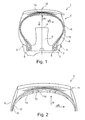
- the Fig. 1 shows a radial section through an inventive wheel system 1 comprising a rim 2 with rim flanges 3, mounted on the rim 2 according to the invention pneumatic vehicle tire 4 and mounted on the rim 2 axially within the vehicle pneumatic tire 4 supporting device 5 whose radial height exceeds the radial height of the rim flanges 3 , wherein in the emergency the support device 5 radially outside the radial height of the rim flanges 3 comes into contact with the pneumatic vehicle tire 4 and receives load.
- the support device 5 is formed in the region of the rim 2 in such a way that in the emergency operation, the bead areas of the pneumatic vehicle tire 4 are pressed against the rim flanges 3 of the rim 2 and thus fixed.
- the pneumatic vehicle tire 4 is a commercial vehicle tire.
- the pneumatic vehicle tire 4 has side walls 6, beads 7 each having a bead core 8, a multi-layer carcass 9, which extends from the zenith region 10 of the pneumatic vehicle tire 4 on the side walls 6 to the bead areas and is anchored there by wrapping tensile bead cores 8, a radially outside of the carcass 9 befindliches tread belt package 11 and a radially disposed within the carcass 9 largely air-impermeable inner layer 12, for example of a halobutyl rubber.
- the pneumatic vehicle tire 4 has in the zenith region 10 an emergency running layer 13 of elastomeric material, which is arranged radially inside the inner layer 12 and thus radially inside the carcass 9.
- the run-flat layer 13 extends closed over the entire circumference of the pneumatic vehicle tire 4.
- the run-flat layer 13 is arranged so that it contacts the support device 5 in emergency operation and then that the load bearing by the support device 5 at least partially in the area then formed contact surface between runflat layer 13th and supporting device 5 takes place.
- the elastomeric material of the run-flat layer 13 contains wax, wherein the weight fraction (wt.%) Of wax on the elastomeric material is greater than the weight fraction of wax on the carcass gumming.
- the run-flat layer 13 is positioned in its axial extent in the pneumatic vehicle tire 4 such that the axial extent of the run-flat layer 13 corresponds at least to the axial extent of the load-bearing surface 14 of the support device 5.
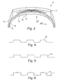
- the Fig. 2 shows a section of a radial section through a pneumatic vehicle tire 4 according to the invention comprising an emergency running layer 13.
- the pneumatic vehicle tire 4 differs from that in Fig. 1 shown pneumatic tire 4 characterized in that the radially outer surface of the run-flat layer 13 has a profile 15 and the adjoining surface of the radially next layer has a profile 15 gegenticianes same.
- the elastomeric material of the run-flat layer contains fat, wherein the weight fraction (wt .-%) of fat on the elastomeric material is greater than the weight fraction of fat in the carcass gumming.
- the run-flat layer 13 deposits 16, which contains a fat as substance friction reducing effect included.
- the run-flat layer 13 has a specific thermal conductivity, which is greater than the specific thermal conductivity of the inner layer 12 and the rubber coating of the carcass 9 under emergency conditions. This is a commercial vehicle tire for military emergency services.
- the Fig. 3 shows a section of a radial section through another inventively designed pneumatic vehicle tire 4 having an emergency running layer 13.
- the pneumatic vehicle tire 4 differs from that in Fig. 1 shown pneumatic tire 4 characterized in that the radially outer surface of the run-flat layer 13 has a profile 15 and the adjoining surface of the radially next layer has a profile 15 gegenticianes same.
- the radially inner surface of the run-flat layer 13 also has a profile 15.
- the elastomeric material of the run-flat layer 13 has, under emergency conditions, a specific thermal conductivity which is higher than the specific thermal conductivity of the inner layer 12.
- FIGS. 4 to 6 each show a portion of a profile 15 of the radially outer and / or the radially inner surface of a run-flat layer 13. For simplicity, the curvature of the run-flat layer 13 is not shown.
Landscapes
- Engineering & Computer Science (AREA)
- Mechanical Engineering (AREA)
- Tires In General (AREA)
Description
- Die Erfindung betrifft einen Fahrzeugluftreifen für ein Radsystem aufweisend eine Felge mit Felgenhörnern, den auf der Felge montierten Fahrzeugluftreifen und eine auf der Felge axial innerhalb des Fahrzeugluftreifens montierte Stützvorrichtung, deren radiale Höhe die radiale Höhe der Felgenhörner übersteigt, wobei im Notlauf die Stützvorrichtung radial außerhalb der radialen Höhe der Felgenhörner mit dem Fahrzeugluftreifen in Berührung kommt und Last aufnimmt, wobei der Fahrzeugluftreifen Seitenwände, Wulste mit Wulstkernen, eine Karkasse, welche vom Zenitbereich des Fahrzeugluftreifens über die Seitenwände bis in die Wulstbereiche reicht und dort durch Umschlingen zugfester Wulstkerne verankert ist, ein radial außerhalb der Karkasse befindliches Laufstreifen-Gürtelpaket und eine radial innerhalb der Karkasse angeordnete Innenschicht aufweist. Weiter betrifft die Erfindung ein Radsystem aufweisend eine Stützvorrichtung und einen solchen Fahrzeugluftreifen.
- Ein solcher Fahrzeugluftreifen ist am Fahrzeug in der Regel luftdicht auf einer Felge montiert. Durch einen Überdruck im Radsystem wird der Fahrzeugluftreifen dabei in Form gehalten. Im Pannenfall eines solchen Fahrzeugluftreifens entweicht in der Regel Luft und der Fahrzeugluftreifen kann nicht mehr oder nicht mehr ausreichend in Form gehalten werden. Bei einem Notlauf, d.h. einer Fahrt mit zu wenig oder keinem Überdruck im Radsystem erfolgt durch Walkarbeit und/oder Reibung eine starke Erhitzung des Fahrzeugluftreifens, welche eine Weiterfahrt des Fahrzeuges erschwert oder unmöglich macht und die Zerstörung des Fahrzeugluftreifens zur Folge haben kann. In einem Pannenfall, beispielsweise einem zivilen oder einem militärischen Pannenfall, kann es aber notwendig sein, dass das Fahrzeug im Notlauf vom Ort des Pannenfalls wegbewegt werden muss.
- Um die Laufleistung im Notlauf zu erhöhen ist es bekannt, auf der Felge axial zwischen den Felgenhörnern eine ringförmige Stützvorrichtung zu montieren, deren radiale Höhe in der Regel die radiale Höhe der Felgenhörner übersteigt. Jeder Wulst des Fahrzeugluftreifens liegt dabei axial zwischen der Stützvorrichtung und einem Felgenhorn. Bei Abplattung im Notlauf liegt der Fahrzeugluftreifen somit nicht primär auf den Felgenhörnern sondern auf der Stützvorrichtung auf, wodurch insbesondere die Wärmeentwicklung im axial äußeren Bereich des Fahrzeugluftreifens stark verringert wird. Die Stützvorrichtung nimmt somit Last auf. Da der radiale Innenumfang des Fahrzeugluftreifens allerdings größer ist als der radiale Außenumfang der Stützvorrichtung, wird durch die Reibung zwischen Fahrzeugluftreifen und Stützvorrichtung bei fortlaufendem Notlauf der Fahrzeugluftreifen und / oder die Stützvorrichtung durch mechanischen Abtrag und / oder Temperatur zerstört. Um die Reibung im Notlauf zu verringern und die Zerstörung des Fahrzeugluftreifens und / oder der Stützvorrichtung hinauszuzögern ist es bekannt, bei der Reifenmontage Fett in das Radsystem zu verfüllen. Dieses ist allerdings schnell verbraucht und im Notlauf nicht am Ort großer Reibung konzentriert sondern im ganzen Radsystem verteilt. Zudem verkompliziert die Verfüllung des Fetts die Montage des Fahrzeugluftreifens auf der Felge.
- Der Erfindung liegt die Aufgabe zugrunde, einen Fahrzeugluftreifen für ein Radsystem mit Stützvorrichtung zur Verfügung zu stellen, der sich durch eine erhöhte Laufleistung des Radsystems im Notlauf sowie durch eine einfachere Montage auszeichnet.
- Die Aufgabe wird gelöst, indem der Fahrzeugluftreifen radial innerhalb der Innenschicht eine Notlaufschicht aus elastomerem Material aufweist, indem das elastomere Material zumindest ein Wachs und / oder zumindest ein Fett enthält, wobei das elastomere Material einen höheren Gewichtsanteil (Gew.-%) an Wachs und / oder an Fett aufweist als die Karkassgummierung und indem die Notlaufschicht so angeordnet ist, dass im Notlauf die Notlaufschicht und die Stützvorrichtung kontaktieren und dass die Lastaufnahme durch die Stützvorrichtung zumindest teilweise im Bereich der Kontaktfläche zwischen Notlaufschicht und Stützvorrichtung erfolgt.
- Der Fahrzeugluftreifen zeichnet sich dadurch aus, dass im Notlauf das Wachs und / oder das Fett die Reibung zwischen Fahrzeugluftreifen und Stützvorrichtung verringert und somit die Laufleistung des Radsystems im Notlauf erhöht ist. Dabei ist die Notlaufschicht so angeordnet, dass im Notlauf die Lastaufnahme durch die Stützvorrichtung zumindest teilweise im Bereich der Kontaktfläche von Notlaufschicht und Stützvorrichtung erfolgt. Stützvorrichtung und Notlaufschicht können dabei zunächst durch eine oder mehrere weitere Schichten in radialer Richtung getrennt sein, welche im Notlauf an der Reibungsfläche zerstört werden, wodurch die Notlaufschicht in direkten Kontakt mit der Stützvorrichtung kommt. Notlaufschicht und Stützvorrichtung werden gegeneinander gepresst. Da an der Kontaktfläche der radial äußere Radius der Stützvorrichtung kleiner ist als der radial innere Radius der Notlaufschicht (gemessen im montierten Zustand ohne Notlauf) reiben Stützvorrichtung und Notlaufschicht im Notlauf aneinander. Das elastomere Material der Notlaufschicht ist durch den Zusatz von Fett und / oder Wachs so ausgebildet, dass es durch mit dem Notlauf einhergehende Belastungen wie erhöhter Druck, erhöhte Temperatur und / oder Reibung eine reibungsmindernde Wirkung zumindest an der Kontaktfläche zur Stützvorrichtung entfaltet. Die reibungsmindernde Wirkung erfolgt somit am Ort großer Reibung, wodurch die mechanische Beanspruchung dort zuverlässig vermindert und auch die mit der Reibung einhergehende Wärmeentwicklung verringert ist. Hierdurch ist die Zerstörung des Fahrzeugluftreifens und/oder der Stützvorrichtung verzögert. Die Laufleistung eines Radsystems aufweisend einen solchen Fahrzeugluftreifens ist somit im Notlauf erhöht.
- Zudem ist die Notlaufschicht ein Bestandteil des Fahrzeugluftreifens, wodurch der Fahrzeugluftreifen einfach zu montieren ist. Ein zusätzlicher Arbeitsschritt, wie das Verfüllen von Fett, ist nicht nötig.
- Zweckmäßig ist es, wenn die Notlaufschicht über den Umfang des Fahrzeugluftreifens geschlossen ist.
- Vorteilhaft ist es, wenn sich das elastomere Material der Notlaufschicht in radialer Richtung ändert, bevorzugt wenn sich der Gewichtsanteil (Gew.-%) an Fett und / oder Wachs des elastomeren Materials in radialer Richtung ändert. Hierdurch kann das Abriebverhalten der Notlaufschicht spezifisch eingestellt werden. Die Reibung kann somit zuverlässig über einen längeren Zeitraum vermindert und die Zerstörung des Fahrzeugluftreifens und/oder des Stützelementes verzögert werden. Die Laufleistung eines solchen Fahrzeugluftreifens im Notlauf ist somit erhöht.
- Es ist vorteilhaft, wenn die Notlaufschicht ein oder mehrere Depots aufweist, welche eine Substanz mit reibungsmindernder Wirkung, insbesondere eine Substanz mit reibungsmindernder Wirkung enthaltend zumindest ein Wachs und / oder zumindest ein Fett, enthalten. Hierdurch wird die reibungsmindernde Wirkung der Notlaufschicht zusätzlich erhöht, wodurch die Laufleistung im Notlauf zusätzlich erhöht wird. Ein Depot ist dabei ein Hohlraum im elastomeren Material, der die Substanz mit reibungsmindernder Wirkung beinhaltet. Die Wand des Depots kann aus einem zum elastomeren Material verschiedenen Material gebildet sein. Depots können die gleiche oder eine unterschiedliche Geometrie aufweisen und die gleiche oder eine unterschiedliche Substanzen beinhalten. Durch die Verteilung der Depots in der Notlaufschicht und/oder die Größe der Depots kann die reibungsmindernde Wirkung gezielt beeinflusst werden.
- Vorteilhaft ist es auch, wenn zwischen der Notlaufschicht und der Karkasse eine Schicht angeordnet ist, die für das Wachs und / oder das Fett des elastomeren Materials der Notlaufschicht weitgehend undurchlässig ist. Hierdurch kann eine Ausbreitung von Wachs und / oder Fett von der Notlaufschicht in andere Bereiche des Reifens vermieden bzw. vermindert werden. Zweckmäßig ist es, wenn die Schicht radial außen an die Notlaufschicht anschließt, insbesondere wenn die Schicht die Innenschicht ist. Zweckmäßig ist es auch, wenn die Schicht die gesamte Innenseite des Fahrzeugluftreifens, zumindest aber die radial äußere Oberfläche der Notlaufschicht, bedeckt. Zweckmäßig ist es auch, wenn die Schicht auf der Oberfläche der Notlaufschicht, insbesondere auf der gesamten Oberfläche der Notlaufschicht, angebracht ist.
- Vorteilhaft ist es, wenn die Notlaufschicht eine spezifische Wärmeleitfähigkeit aufweist, die größer ist als die spezifische Wärmeleitfähigkeit der Innenschicht und/oder die größer ist als die spezifische Wärmeleitfähigkeit der Karkassgummierung, insbesondere unter Notlaufbedingungen. Hierdurch ist eine schnelle Ableitung der im Notlauf entstehenden Wärme gewährleistet, wodurch die Laufleistung erhöht ist.
- Zweckmäßig ist es, wenn die Innenschichtmischung auf einem Halobutyl-Kautschuk oder einer Innenschichtmischung für Schlauchreifen basiert.
- Vorteilhaft ist es auch, wenn die Notlaufschicht so angeordnet ist, dass die axiale Ausdehnung der Notlaufschicht zumindest der axialen Ausdehnung der im Notlauf Last aufnehmenden Oberfläche der Stützvorrichtung entspricht. Hierdurch kann sich die reibungsmindernde Wirkung im Notlauf auf der gesamten Last aufnehmenden Oberfläche der Stützvorrichtung entfalten.
- In einer bevorzugten Ausführungsform weist die radial innere Oberfläche der Notlaufschicht ein Profil auf. Hierdurch ist die Austrittsoberfläche für das Wachs und / oder Fett vergrößert und das Fahrverhalten den Radsystems verbessert. Bevorzugt weist das Profil dabei Profilrillen in Umfangsrichtung auf.
- In einer weiteren bevorzugten Ausführungsform weist die radial äußere Oberfläche der Notlaufschicht ein Profil und die daran angrenzende Oberfläche der radial nächsten Schicht ein dazu gegengleiches Profil auf. Hierdurch ist die Kontaktoberfläche zwischen den Schichten erhöht, wodurch der Zusammenhalt der Schichten durch die vergrößerte Oberfläche, die für eine Verbindung durch Vulkanisation und/oder eine elastische Klebeverbindung zur Verfügung steht, im Vergleich zu einer unprofilierten Oberfläche verbessert ist. Vorteilhaft ist eine Profilierung zudem zur Bewältigung von im Notlauf auftretenden Kräften wie Seiten- und/oder Torsionskräften. Bevorzugt weist das Profil dabei Profilrillen in Umfangsrichtung auf.
- Eine Erhöhung der Laufleistung im Notlauf ist vorteilhaft für Nutzfahrzeugreifen. Insbesondere für Nutzfahrzeugreifen für Militärfahrzeuge, für Feuelwehlfahrzeuge, für Unimogs, für Off-Road-Fahrzeuge oder für ein Fahrzeug für den Einsatz in Steinbrüchen, Minen oder als Kran, ist die zuverlässige Erhöhung der Laufleistung im Notlauf vorteilhaft.
- Die Erfindung umfasst auch ein Radsystem für Kraftfahrzeuge aufweisend eine Felge mit Felgenhörnern, einen auf der Felge montierten Fahrzeugluftreifen aufweisend eine Notlaufschicht aus elastomerem Material enthaltend Wachs und / oder Fett und eine auf der Felge axial innerhalb des Fahrzeugluftreifens montierte Stützvorrichtung, deren radiale Höhe die radiale Höhe der Felgenhörner übersteigt, wobei im Notlauf der Zenitbereich des Fahrzeugluftreifens mit der Stützvorrichtung in Berührung kommt und die Stützvorrichtung Last aufnimmt.
- Die reibungsmindernde Wirkung des Fettes und / oder Waches des elastomeren Materials der Notlaufschicht sorgt so für eine kontinuierliche Verminderung der Reibung an der Kontaktfläche zwischen der Notlaufschicht und dem Stützelement. Das die unter der mit dem Notlauf einhergehenden Belastung reibungsmindernde elastomere Material der Notlaufschicht wird somit am Ort großer Reibung zur Verfügung gestellt, wodurch die Reibung dort zuverlässig vermindert und die Zerstörung des Fahrzeugluftreifens und/oder der Stützvorrichtung verzögert wird. Die Laufleistung eines solchen Fahrzeugluftreifens im Notlauf ist somit erhöht. Zudem ist die Notlaufschicht ein Bestandteil des Fahrzeugluftreifens, wodurch der Fahrzeugluftreifen des Radsystems einfach auf zu montieren ist. Ein zusätzlicher Arbeitsschritt, wie das Verfüllen von Fett, ist nicht nötig.
- Vorzugsweise ist das Stützelement so ausgebildet, dass es die Wülste des Fahrzeugluftreifens zumindest im Notlauf gegen die Felgenhörner presst und auf der Felge fixiert.
- Weitere Merkmale, Vorteile und Einzelheiten der Erfindung werden nun anhand der Figuren, die schematische Ausführungsbeispiele darstellen, näher beschrieben. Dabei zeigt die:
-
Fig. 1 einen Radialschnitt durch ein erfindungsgemäßes Radsystem; -
Fig. 2 undFig. 3 jeweils einen Teilradialschnitt durch einen erfindungsgemäßen Fahrzeugluftreifen; -
Fig. 4 bis Fig. 6 jeweils einen Abschnitts eines Profils einer Oberfläche einer Notlaufschicht. - Die
Fig. 1 zeigt einen Radialschnitt durch ein erfindungsgemäßes Radsystem 1 aufweisend eine Felge 2 mit Felgenhörnern 3, einen auf der Felge 2 montierten erfindungsgemäßen Fahrzeugluftreifen 4 und eine auf der Felge 2 axial innerhalb des Fahrzeugluftreifens 4 montierte Stützvorrichtung 5, deren radiale Höhe die radiale Höhe der Felgenhörner 3 übersteigt, wobei im Notlauf die Stützvorrichtung 5 radial außerhalb der radialen Höhe der Felgenhörner 3 mit dem Fahrzeugluftreifen 4 in Berührung kommt und Last aufnimmt. Die Stützvorrichtung 5 ist dabei im Bereich der Felge 2 so ausgebildet, dass im Notlauf die Wulstbereiche des Fahrzeugluftreifens 4 gegen die Felgenhörner 3 der Felge 2 gepresst und somit fixiert werden. Der Fahrzeugluftreifen 4 ist dabei ein Nutzfahrzeugreifen. Der Fahrzeugluftreifen 4 weist Seitenwände 6, Wulste 7 mit je einem Wulstkern 8, eine mehrlagige Karkasse 9, welche vom Zenitbereich 10 des Fahrzeugluftreifens 4 über die Seitenwände 6 bis in die Wulstbereiche reicht und dort durch Umschlingen zugfester Wulstkerne 8 verankert ist, ein radial außerhalb der Karkasse 9 befindliches Laufstreifen-Gürtelpaket 11 und eine radial innerhalb der Karkasse 9 angeordnete weitgehend luftundurchlässige Innenschicht 12, beispielsweise aus einem Halobutyl-Kautschuk, aufweist. - Der Fahrzeugluftreifen 4 weist im Zenitbereich 10 eine Notlaufschicht 13 aus elastomerem Material auf, welche radial innerhalb der Innenschicht 12 und somit radial innerhalb der Karkasse 9 angeordnet ist. Die Notlaufschicht 13 erstreckt sich geschlossen über den gesamten Umfang des Fahrzeugluftreifens 4. Die Notlaufschicht 13 ist dabei so angeordnet, dass sie im Notlauf die Stützvorrichtung 5 kontaktiert und dass dann die Lastaufnahme durch die Stützvorrichtung 5 zumindest teilweise im Bereich der dann entstandenen Kontaktfläche zwischen Notlaufschicht 13 und Stützvorrichtung 5 erfolgt. Das elastomere Material der Notlaufschicht 13 enthält Wachs, wobei der Gewichtsanteil (Gew.-%) von Wachs am elastomeren Material größer ist als der Gewichtsanteil von Wachs an der Karkassgummierung. Die Notlaufschicht 13 ist in ihrer axialen Ausdehnung im Fahrzeugluftreifen 4 so positioniert, dass die axiale Ausdehnung der Notlaufschicht 13 zumindest der axialen Ausdehnung der im Notlauf Last aufnehmenden Oberfläche 14 der Stützvorrichtung 5 entspricht.
- Die
Fig. 2 zeigt einen Ausschnitt eines Radialschnittes durch einen erfindungsgemäßen Fahrzeugluftreifen 4 aufweisend eine Notlaufschicht 13. Der Fahrzeugluftreifen 4 unterscheidet sich von dem inFig. 1 gezeigten Fahrzeugluftreifen 4 dadurch, dass die radial äußere Oberfläche der Notlaufschicht 13 ein Profil 15 und die daran angrenzende Oberfläche der radial nächsten Schicht ein dazu gegengleiches Profil 15 aufweist. Zudem enthält das elastomere Material der Notlaufschicht Fett, wobei der Gewichtsanteil (Gew.-%) an Fett am elastomeren Material größer ist als der Gewichtsanteil an Fett an der Karkassgummierung. Weiter weist die Notlaufschicht 13 Depots 16 auf, welche ein Fett als Substanz mit reibungsmindernder Wirkung enthalten. Die Notlaufschicht 13 weist eine spezifische Wärmeleitfähigkeit auf, die unter Notlaufbedingungen größer ist als die spezifische Wärmeleitfähigkeit der Innenschicht 12 und der Gummierung der Karkasse 9. Es handelt sich dabei um einen Nutzfahrzeugreifen für militärische Einsatzkräfte. - Die
Fig. 3 zeigt einen Ausschnitt eines Radialschnittes durch einen weiteren erfindungsgemäß ausgeführten Fahrzeugluftreifen 4 aufweisend eine Notlaufschicht 13. Der Fahrzeugluftreifen 4 unterscheidet sich von dem inFig. 1 gezeigten Fahrzeugluftreifen 4 dadurch, dass die radial äußere Oberfläche der Notlaufschicht 13 ein Profil 15 und die daran angrenzende Oberfläche der radial nächsten Schicht ein dazu gegengleiches Profil 15 aufweist. Auch die radial innere Oberfläche der Notlaufschicht 13 weist ein Profil 15 auf. Das elastomere Material der Notlaufschicht 13 weist unter Notlaufbedingungen eine spezifische Wärmeleitfähigkeit auf, die höher ist als die spezifische Wärmeleitfähigkeit der Innenschicht 12. - Die
Figuren 4 bis 6 zeigen jeweils einen Abschnitt eines Profils 15 der radial äußeren und / oder der radial inneren Oberfläche einer Notlaufschicht 13. Der Einfachheit halber ist die Krümmung der Notlaufschicht 13 nicht dargestellt. - (Teil der Beschreibung)
- 1
- Radsystem
- 2
- Felge
- 3
- Felgenhorn
- 4
- Fahrzeugluftreifen
- 5
- Stützvorrichtung
- 6
- Seitenwand
- 7
- Wulst
- 8
- Wulstkern
- 9
- Karkasse
- 10
- Zenitbereich
- 11
- Laufstreifen-Gürtelpaket
- 12
- Innenschicht
- 13
- Notlaufschicht
- 14
- Last aufnehmende Oberfläche
- 15
- Profil
- 16
- Depot
- rR
- radiale Richtung
- aR
- axiale Richtung
- U
- Umfangsrichtung
Claims (10)
- Fahrzeugluftreifen (4) für ein Radsystem (1) aufweisend eine• Felge (2) mit Felgenhörnern,• den auf der Felge (2) montierten Fahrzeugluftreifen (4) und• eine auf der Felge (2) axial innerhalb des Fahrzeugluftreifens (4) montierte Stützvorrichtung (5), deren radiale Höhe die radiale Höhe der Felgenhörner (3) übersteigt, wobei im Notlauf die Stützvorrichtung (5) radial außerhalb der radialen Höhe der Felgenhörner (3) mit dem Fahrzeugluftreifen (4) in Berührung kommt und Last aufnimmt,• wobei der Fahrzeugluftreifen (4) Seitenwände (6), Wulste (7) mit Wulstkernen (8), eine Karkasse (9), welche vom Zenitbereich (10) des Fahrzeugluftreifens (4) über die Seitenwände (6) bis in die Wulstbereiche reicht und dort durch Umschlingen zugfester Wulstkerne (8) verankert ist, ein radial außerhalb der Karkasse (9) befindliches Laufstreifen-Gürtelpaket (11) und eine radial innerhalb der Karkasse (9) angeordnete Innenschicht (12) aufweistdadurch gekennzeichnet, dass• der Fahrzeugluftreifen (4) radial innerhalb der Innenschicht (12) eine Notlaufschicht (13) aus elastomerem Material aufweist,• dass das elastomere Material zumindest ein Wachs und / oder zumindest ein Fett enthält, wobei das elastomere Material einen höheren Gewichtsanteil (Gew.-%) an Wachs und / oder an Fett als die Karkassgummierung aufweist und• dass die Notlaufschicht (13) so angeordnet ist, dass im Notlauf die Notlaufschicht (13) und die Stützvorrichtung (5) kontaktieren und dass die Lastaufnahme durch die Stützvorrichtung (5) zumindest teilweise im Bereich der Kontaktfläche zwischen Notlaufschicht (13) und Stützvorrichtung (5) erfolgt.
- Fahrzeugluftreifen (4) nach Anspruch 1, dadurch gekennzeichnet, dass sich das elastomere Material der Notlaufschicht (13) in radialer Richtung ändert, bevorzugt dass sich der Gewichtsanteil (Gew.-%) an Fett und / oder Wachs des elastomeren Materials in radialer Richtung ändert.
- Fahrzeugluftreifen (4) nach einem der Ansprüche 1 oder 2, dadurch gekennzeichnet, dass die Notlaufschicht (13) ein oder mehrere Depots (16) aufweist, welche eine Substanz mit reibungsmindernder Wirkung, insbesondere eine Substanz mit reibungsmindernder Wirkung enthaltend zumindest ein Wachs und / oder zumindest ein Fett, enthalten.
- Fahrzeugluftreifen (4) nach einem der Ansprüche 1 bis 3, dadurch gekennzeichnet, dass zwischen der Notlaufschicht (13) und der Karkasse (9) eine Schicht angeordnet ist, die für das Wachs und / oder das Fett des elastomeren Materials der Notlaufschicht (13) weitgehend undurchlässig ist.
- Fahrzeugluftreifen (4) nach einem der Ansprüche 1 bis 4, dadurch gekennzeichnet, dass die Notlaufschicht (13) eine spezifische Wärmeleitfähigkeit aufweist, die größer ist als die spezifische Wärmeleitfähigkeit der Innenschicht (12) und/oder die größer ist als die spezifische Wärmeleitfähigkeit der Karkassgummierung.
- Fahrzeugluftreifen (4) nach einem der Ansprüche 1 bis 5, dadurch gekennzeichnet, dass die Notlaufschicht (13) so angeordnet ist, dass die axiale Ausdehnung der Notlaufschicht (13) zumindest der axialen Ausdehnung der im Notlauf Last aufnehmenden Oberfläche (14) der Stützvorrichtung (5) entspricht.
- Fahrzeugluftreifen (4) nach einem der Ansprüche 1 bis 6, dadurch gekennzeichnet, dass die radial innere Oberfläche der Notlaufschicht (13) ein Profil (15) aufweist.
- Fahrzeugluftreifen (4) nach einem der Ansprüche 1 bis 7, dadurch gekennzeichnet, dass die radial äußere Oberfläche der Notlaufschicht (13) ein Profil (15) aufweist und dass die daran angrenzende Oberfläche der radial nächsten Schicht ein dazu gegengleiches Profil (15) aufweist.
- Fahrzeugluftreifen (4) nach einem der Ansprüche 1 bis 8, dadurch gekennzeichnet, dass es sich um einen Nutzfahrzeugreifen, bevorzugt um einen Nutzfahrzeugreifen für ein Militärfahrzeug, ein Feuerwehrfahrzeug, ein Unimog, ein Off-Road-Fahrzeug oder ein Fahrzeug für den Einsatz in Steinbrüchen, Minen oder als Kran, handelt.
- Radsystem (1) für Kraftfahrzeuge aufweisend eine Felge (2) mit Felgenhörnern (3), einen auf der Felge (2) montierten Fahrzeugluftreifen (4) gemäß zumindest einem der Ansprüche 1 bis 9 aufweisend eine Notlaufschicht (13) aus elastomerem Material enthaltend Wachs und / oder Fett und eine auf der Felge (2) axial innerhalb des Fahrzeugluftreifens (4) montierte Stützvorrichtung (5), deren radiale Höhe die radiale Höhe der Felgenhörner (3) übersteigt, wobei im Notlauf die Stützvorrichtung (5) radial außerhalb der radialen Höhe der Felgenhörner (3) mit dem Fahrzeugluftreifen (4) in Berührung kommt und Last aufnimmt.
Applications Claiming Priority (1)
| Application Number | Priority Date | Filing Date | Title |
|---|---|---|---|
| DE102014225108.7A DE102014225108A1 (de) | 2014-12-08 | 2014-12-08 | Fahrzeugluftreifen aufweisend eine Notlaufschicht |
Publications (2)
| Publication Number | Publication Date |
|---|---|
| EP3031631A1 true EP3031631A1 (de) | 2016-06-15 |
| EP3031631B1 EP3031631B1 (de) | 2019-07-03 |
Family
ID=54072726
Family Applications (1)
| Application Number | Title | Priority Date | Filing Date |
|---|---|---|---|
| EP15184377.8A Active EP3031631B1 (de) | 2014-12-08 | 2015-09-09 | Fahrzeugluftreifen aufweisend eine notlaufschicht |
Country Status (2)
| Country | Link |
|---|---|
| EP (1) | EP3031631B1 (de) |
| DE (1) | DE102014225108A1 (de) |
Cited By (1)
| Publication number | Priority date | Publication date | Assignee | Title |
|---|---|---|---|---|
| WO2020203562A1 (ja) * | 2019-04-04 | 2020-10-08 | 横浜ゴム株式会社 | 自動二輪車用タイヤ |
Families Citing this family (2)
| Publication number | Priority date | Publication date | Assignee | Title |
|---|---|---|---|---|
| CN110481247B (zh) * | 2019-08-28 | 2024-05-31 | 青岛海琅智能装备有限公司 | 一种汽车爆胎应急安全装置 |
| CN112677717A (zh) * | 2021-01-19 | 2021-04-20 | 深圳市朗琴信息科技有限公司 | 基于大数据技术的汽车轮胎实时安全状态检测设备 |
Citations (6)
| Publication number | Priority date | Publication date | Assignee | Title |
|---|---|---|---|---|
| US2987093A (en) * | 1957-07-22 | 1961-06-06 | Goodyear Tire & Rubber | Multiple chambered tire |
| EP0140074A2 (de) * | 1983-10-27 | 1985-05-08 | Continental Aktiengesellschaft | Fahrzeugrad |
| EP0142844A2 (de) * | 1983-11-21 | 1985-05-29 | Uniroyal Englebert Reifen GmbH | Luftreifen-Fahrzeugrad mit einer Notlaufstütze |
| EP0158039A1 (de) * | 1984-02-21 | 1985-10-16 | Uniroyal Englebert Reifen GmbH | Luftreifen-Fahrzeugrad mit einer Notlaufstütze |
| US20030226628A1 (en) * | 2002-04-30 | 2003-12-11 | Bailey Rodney R. | Deflated tire lubricant |
| US20040147408A1 (en) * | 2003-01-17 | 2004-07-29 | Kollin Edward B. | Lubricants for run-flat tire systems |
-
2014
- 2014-12-08 DE DE102014225108.7A patent/DE102014225108A1/de not_active Withdrawn
-
2015
- 2015-09-09 EP EP15184377.8A patent/EP3031631B1/de active Active
Patent Citations (6)
| Publication number | Priority date | Publication date | Assignee | Title |
|---|---|---|---|---|
| US2987093A (en) * | 1957-07-22 | 1961-06-06 | Goodyear Tire & Rubber | Multiple chambered tire |
| EP0140074A2 (de) * | 1983-10-27 | 1985-05-08 | Continental Aktiengesellschaft | Fahrzeugrad |
| EP0142844A2 (de) * | 1983-11-21 | 1985-05-29 | Uniroyal Englebert Reifen GmbH | Luftreifen-Fahrzeugrad mit einer Notlaufstütze |
| EP0158039A1 (de) * | 1984-02-21 | 1985-10-16 | Uniroyal Englebert Reifen GmbH | Luftreifen-Fahrzeugrad mit einer Notlaufstütze |
| US20030226628A1 (en) * | 2002-04-30 | 2003-12-11 | Bailey Rodney R. | Deflated tire lubricant |
| US20040147408A1 (en) * | 2003-01-17 | 2004-07-29 | Kollin Edward B. | Lubricants for run-flat tire systems |
Cited By (2)
| Publication number | Priority date | Publication date | Assignee | Title |
|---|---|---|---|---|
| WO2020203562A1 (ja) * | 2019-04-04 | 2020-10-08 | 横浜ゴム株式会社 | 自動二輪車用タイヤ |
| JP2020168981A (ja) * | 2019-04-04 | 2020-10-15 | 横浜ゴム株式会社 | 自動二輪車用タイヤ |
Also Published As
| Publication number | Publication date |
|---|---|
| EP3031631B1 (de) | 2019-07-03 |
| DE102014225108A1 (de) | 2016-06-09 |
Similar Documents
| Publication | Publication Date | Title |
|---|---|---|
| DE19825311C1 (de) | Fahrzeugrad mit einem Notlaufstützkörper | |
| EP3031631B1 (de) | Fahrzeugluftreifen aufweisend eine notlaufschicht | |
| DE102014207771A1 (de) | Fahrzeugluftreifen mit Squeegeelage | |
| WO2017005380A1 (de) | Fahrzeugluftreifen | |
| EP3012123B1 (de) | Fahrzeugluftreifen | |
| WO2009053131A1 (de) | Fahrzeugluftreifen | |
| DE2529597A1 (de) | Sicherheitsreifen | |
| WO2016193310A1 (de) | Drucksicherungs-vorrichtung für druckluft gefüllte räder und verfahren dazu | |
| DE102014225107A1 (de) | Notlaufstützvorrichtung aufweisend einen Notlaufring | |
| EP3061627B1 (de) | Nutzfahrzeugreifen mit niedriger querschnittshöhe | |
| EP2978615B1 (de) | Fahrzeugluftreifen | |
| EP2979905B1 (de) | Fahrzeugluftreifen | |
| DE102016216732A1 (de) | Fahrzeugluftreifen mit Notlaufeigenschaften | |
| DE102007049873A1 (de) | Fahrzeugluftreifen mit Notlaufeigenschaften | |
| DE102012107606A1 (de) | Selbstdichtender Fahrzeugluftreifen | |
| DE10139208B4 (de) | Fahrzeugluftreifen mit Wulstprofil | |
| WO2019115055A1 (de) | Fahrzeugluftreifen | |
| EP1535763B1 (de) | Verfahren zur Herstellung eines Fahrzeugluftreifens | |
| DE4428516A1 (de) | Fahrzeugreifen | |
| DE102006050471B4 (de) | Fahrzeugluftreifen | |
| EP4520547A1 (de) | Fahrzeugreifen | |
| DE102021207965A1 (de) | Fahrzeugluftreifen | |
| DE1680441B2 (de) | Kraftfahrzeug-sicherheitsreifen | |
| DE102009003337A1 (de) | Fahrzeugluftreifen | |
| DE102021127954A1 (de) | Reifen, reifenform und reifen-herstellungsverfahren |
Legal Events
| Date | Code | Title | Description |
|---|---|---|---|
| PUAI | Public reference made under article 153(3) epc to a published international application that has entered the european phase |
Free format text: ORIGINAL CODE: 0009012 |
|
| AK | Designated contracting states |
Kind code of ref document: A1 Designated state(s): AL AT BE BG CH CY CZ DE DK EE ES FI FR GB GR HR HU IE IS IT LI LT LU LV MC MK MT NL NO PL PT RO RS SE SI SK SM TR |
|
| AX | Request for extension of the european patent |
Extension state: BA ME |
|
| STAA | Information on the status of an ep patent application or granted ep patent |
Free format text: STATUS: REQUEST FOR EXAMINATION WAS MADE |
|
| 17P | Request for examination filed |
Effective date: 20161215 |
|
| RBV | Designated contracting states (corrected) |
Designated state(s): AL AT BE BG CH CY CZ DE DK EE ES FI FR GB GR HR HU IE IS IT LI LT LU LV MC MK MT NL NO PL PT RO RS SE SI SK SM TR |
|
| RIC1 | Information provided on ipc code assigned before grant |
Ipc: B60C 17/04 20060101ALI20190206BHEP Ipc: B60C 17/06 20060101ALI20190206BHEP Ipc: B60C 17/00 20060101ALI20190206BHEP Ipc: B60C 17/10 20060101AFI20190206BHEP |
|
| GRAP | Despatch of communication of intention to grant a patent |
Free format text: ORIGINAL CODE: EPIDOSNIGR1 |
|
| STAA | Information on the status of an ep patent application or granted ep patent |
Free format text: STATUS: GRANT OF PATENT IS INTENDED |
|
| INTG | Intention to grant announced |
Effective date: 20190319 |
|
| GRAS | Grant fee paid |
Free format text: ORIGINAL CODE: EPIDOSNIGR3 |
|
| GRAA | (expected) grant |
Free format text: ORIGINAL CODE: 0009210 |
|
| STAA | Information on the status of an ep patent application or granted ep patent |
Free format text: STATUS: THE PATENT HAS BEEN GRANTED |
|
| AK | Designated contracting states |
Kind code of ref document: B1 Designated state(s): AL AT BE BG CH CY CZ DE DK EE ES FI FR GB GR HR HU IE IS IT LI LT LU LV MC MK MT NL NO PL PT RO RS SE SI SK SM TR |
|
| REG | Reference to a national code |
Ref country code: GB Ref legal event code: FG4D Free format text: NOT ENGLISH |
|
| REG | Reference to a national code |
Ref country code: CH Ref legal event code: EP Ref country code: AT Ref legal event code: REF Ref document number: 1150545 Country of ref document: AT Kind code of ref document: T Effective date: 20190715 |
|
| REG | Reference to a national code |
Ref country code: IE Ref legal event code: FG4D Free format text: LANGUAGE OF EP DOCUMENT: GERMAN |
|
| REG | Reference to a national code |
Ref country code: DE Ref legal event code: R096 Ref document number: 502015009499 Country of ref document: DE |
|
| REG | Reference to a national code |
Ref country code: NL Ref legal event code: MP Effective date: 20190703 |
|
| REG | Reference to a national code |
Ref country code: LT Ref legal event code: MG4D |
|
| PG25 | Lapsed in a contracting state [announced via postgrant information from national office to epo] |
Ref country code: NO Free format text: LAPSE BECAUSE OF FAILURE TO SUBMIT A TRANSLATION OF THE DESCRIPTION OR TO PAY THE FEE WITHIN THE PRESCRIBED TIME-LIMIT Effective date: 20191003 Ref country code: NL Free format text: LAPSE BECAUSE OF FAILURE TO SUBMIT A TRANSLATION OF THE DESCRIPTION OR TO PAY THE FEE WITHIN THE PRESCRIBED TIME-LIMIT Effective date: 20190703 Ref country code: PT Free format text: LAPSE BECAUSE OF FAILURE TO SUBMIT A TRANSLATION OF THE DESCRIPTION OR TO PAY THE FEE WITHIN THE PRESCRIBED TIME-LIMIT Effective date: 20191104 Ref country code: BG Free format text: LAPSE BECAUSE OF FAILURE TO SUBMIT A TRANSLATION OF THE DESCRIPTION OR TO PAY THE FEE WITHIN THE PRESCRIBED TIME-LIMIT Effective date: 20191003 Ref country code: SE Free format text: LAPSE BECAUSE OF FAILURE TO SUBMIT A TRANSLATION OF THE DESCRIPTION OR TO PAY THE FEE WITHIN THE PRESCRIBED TIME-LIMIT Effective date: 20190703 Ref country code: LT Free format text: LAPSE BECAUSE OF FAILURE TO SUBMIT A TRANSLATION OF THE DESCRIPTION OR TO PAY THE FEE WITHIN THE PRESCRIBED TIME-LIMIT Effective date: 20190703 Ref country code: HR Free format text: LAPSE BECAUSE OF FAILURE TO SUBMIT A TRANSLATION OF THE DESCRIPTION OR TO PAY THE FEE WITHIN THE PRESCRIBED TIME-LIMIT Effective date: 20190703 Ref country code: FI Free format text: LAPSE BECAUSE OF FAILURE TO SUBMIT A TRANSLATION OF THE DESCRIPTION OR TO PAY THE FEE WITHIN THE PRESCRIBED TIME-LIMIT Effective date: 20190703 Ref country code: CZ Free format text: LAPSE BECAUSE OF FAILURE TO SUBMIT A TRANSLATION OF THE DESCRIPTION OR TO PAY THE FEE WITHIN THE PRESCRIBED TIME-LIMIT Effective date: 20190703 |
|
| PG25 | Lapsed in a contracting state [announced via postgrant information from national office to epo] |
Ref country code: ES Free format text: LAPSE BECAUSE OF FAILURE TO SUBMIT A TRANSLATION OF THE DESCRIPTION OR TO PAY THE FEE WITHIN THE PRESCRIBED TIME-LIMIT Effective date: 20190703 Ref country code: GR Free format text: LAPSE BECAUSE OF FAILURE TO SUBMIT A TRANSLATION OF THE DESCRIPTION OR TO PAY THE FEE WITHIN THE PRESCRIBED TIME-LIMIT Effective date: 20191004 Ref country code: IS Free format text: LAPSE BECAUSE OF FAILURE TO SUBMIT A TRANSLATION OF THE DESCRIPTION OR TO PAY THE FEE WITHIN THE PRESCRIBED TIME-LIMIT Effective date: 20191103 Ref country code: RS Free format text: LAPSE BECAUSE OF FAILURE TO SUBMIT A TRANSLATION OF THE DESCRIPTION OR TO PAY THE FEE WITHIN THE PRESCRIBED TIME-LIMIT Effective date: 20190703 Ref country code: LV Free format text: LAPSE BECAUSE OF FAILURE TO SUBMIT A TRANSLATION OF THE DESCRIPTION OR TO PAY THE FEE WITHIN THE PRESCRIBED TIME-LIMIT Effective date: 20190703 Ref country code: AL Free format text: LAPSE BECAUSE OF FAILURE TO SUBMIT A TRANSLATION OF THE DESCRIPTION OR TO PAY THE FEE WITHIN THE PRESCRIBED TIME-LIMIT Effective date: 20190703 |
|
| PG25 | Lapsed in a contracting state [announced via postgrant information from national office to epo] |
Ref country code: TR Free format text: LAPSE BECAUSE OF FAILURE TO SUBMIT A TRANSLATION OF THE DESCRIPTION OR TO PAY THE FEE WITHIN THE PRESCRIBED TIME-LIMIT Effective date: 20190703 |
|
| PG25 | Lapsed in a contracting state [announced via postgrant information from national office to epo] |
Ref country code: IT Free format text: LAPSE BECAUSE OF FAILURE TO SUBMIT A TRANSLATION OF THE DESCRIPTION OR TO PAY THE FEE WITHIN THE PRESCRIBED TIME-LIMIT Effective date: 20190703 Ref country code: RO Free format text: LAPSE BECAUSE OF FAILURE TO SUBMIT A TRANSLATION OF THE DESCRIPTION OR TO PAY THE FEE WITHIN THE PRESCRIBED TIME-LIMIT Effective date: 20190703 Ref country code: EE Free format text: LAPSE BECAUSE OF FAILURE TO SUBMIT A TRANSLATION OF THE DESCRIPTION OR TO PAY THE FEE WITHIN THE PRESCRIBED TIME-LIMIT Effective date: 20190703 Ref country code: PL Free format text: LAPSE BECAUSE OF FAILURE TO SUBMIT A TRANSLATION OF THE DESCRIPTION OR TO PAY THE FEE WITHIN THE PRESCRIBED TIME-LIMIT Effective date: 20190703 Ref country code: DK Free format text: LAPSE BECAUSE OF FAILURE TO SUBMIT A TRANSLATION OF THE DESCRIPTION OR TO PAY THE FEE WITHIN THE PRESCRIBED TIME-LIMIT Effective date: 20190703 |
|
| PG25 | Lapsed in a contracting state [announced via postgrant information from national office to epo] |
Ref country code: MC Free format text: LAPSE BECAUSE OF FAILURE TO SUBMIT A TRANSLATION OF THE DESCRIPTION OR TO PAY THE FEE WITHIN THE PRESCRIBED TIME-LIMIT Effective date: 20190703 Ref country code: SK Free format text: LAPSE BECAUSE OF FAILURE TO SUBMIT A TRANSLATION OF THE DESCRIPTION OR TO PAY THE FEE WITHIN THE PRESCRIBED TIME-LIMIT Effective date: 20190703 Ref country code: IS Free format text: LAPSE BECAUSE OF FAILURE TO SUBMIT A TRANSLATION OF THE DESCRIPTION OR TO PAY THE FEE WITHIN THE PRESCRIBED TIME-LIMIT Effective date: 20200224 Ref country code: SM Free format text: LAPSE BECAUSE OF FAILURE TO SUBMIT A TRANSLATION OF THE DESCRIPTION OR TO PAY THE FEE WITHIN THE PRESCRIBED TIME-LIMIT Effective date: 20190703 |
|
| REG | Reference to a national code |
Ref country code: CH Ref legal event code: PL |
|
| REG | Reference to a national code |
Ref country code: DE Ref legal event code: R097 Ref document number: 502015009499 Country of ref document: DE |
|
| PLBE | No opposition filed within time limit |
Free format text: ORIGINAL CODE: 0009261 |
|
| STAA | Information on the status of an ep patent application or granted ep patent |
Free format text: STATUS: NO OPPOSITION FILED WITHIN TIME LIMIT |
|
| PG2D | Information on lapse in contracting state deleted |
Ref country code: IS |
|
| PG25 | Lapsed in a contracting state [announced via postgrant information from national office to epo] |
Ref country code: LI Free format text: LAPSE BECAUSE OF NON-PAYMENT OF DUE FEES Effective date: 20190930 Ref country code: IE Free format text: LAPSE BECAUSE OF NON-PAYMENT OF DUE FEES Effective date: 20190909 Ref country code: CH Free format text: LAPSE BECAUSE OF NON-PAYMENT OF DUE FEES Effective date: 20190930 Ref country code: LU Free format text: LAPSE BECAUSE OF NON-PAYMENT OF DUE FEES Effective date: 20190909 |
|
| REG | Reference to a national code |
Ref country code: BE Ref legal event code: MM Effective date: 20190930 |
|
| 26N | No opposition filed |
Effective date: 20200603 |
|
| PG25 | Lapsed in a contracting state [announced via postgrant information from national office to epo] |
Ref country code: BE Free format text: LAPSE BECAUSE OF NON-PAYMENT OF DUE FEES Effective date: 20190930 Ref country code: SI Free format text: LAPSE BECAUSE OF FAILURE TO SUBMIT A TRANSLATION OF THE DESCRIPTION OR TO PAY THE FEE WITHIN THE PRESCRIBED TIME-LIMIT Effective date: 20190703 |
|
| GBPC | Gb: european patent ceased through non-payment of renewal fee |
Effective date: 20191003 |
|
| PG25 | Lapsed in a contracting state [announced via postgrant information from national office to epo] |
Ref country code: FR Free format text: LAPSE BECAUSE OF NON-PAYMENT OF DUE FEES Effective date: 20190930 Ref country code: GB Free format text: LAPSE BECAUSE OF NON-PAYMENT OF DUE FEES Effective date: 20191003 |
|
| PG25 | Lapsed in a contracting state [announced via postgrant information from national office to epo] |
Ref country code: CY Free format text: LAPSE BECAUSE OF FAILURE TO SUBMIT A TRANSLATION OF THE DESCRIPTION OR TO PAY THE FEE WITHIN THE PRESCRIBED TIME-LIMIT Effective date: 20190703 |
|
| PG25 | Lapsed in a contracting state [announced via postgrant information from national office to epo] |
Ref country code: MT Free format text: LAPSE BECAUSE OF FAILURE TO SUBMIT A TRANSLATION OF THE DESCRIPTION OR TO PAY THE FEE WITHIN THE PRESCRIBED TIME-LIMIT Effective date: 20190703 Ref country code: HU Free format text: LAPSE BECAUSE OF FAILURE TO SUBMIT A TRANSLATION OF THE DESCRIPTION OR TO PAY THE FEE WITHIN THE PRESCRIBED TIME-LIMIT; INVALID AB INITIO Effective date: 20150909 |
|
| REG | Reference to a national code |
Ref country code: AT Ref legal event code: MM01 Ref document number: 1150545 Country of ref document: AT Kind code of ref document: T Effective date: 20200909 |
|
| PG25 | Lapsed in a contracting state [announced via postgrant information from national office to epo] |
Ref country code: AT Free format text: LAPSE BECAUSE OF NON-PAYMENT OF DUE FEES Effective date: 20200909 |
|
| PG25 | Lapsed in a contracting state [announced via postgrant information from national office to epo] |
Ref country code: MK Free format text: LAPSE BECAUSE OF FAILURE TO SUBMIT A TRANSLATION OF THE DESCRIPTION OR TO PAY THE FEE WITHIN THE PRESCRIBED TIME-LIMIT Effective date: 20190703 |
|
| REG | Reference to a national code |
Ref country code: DE Ref legal event code: R081 Ref document number: 502015009499 Country of ref document: DE Owner name: CONTINENTAL REIFEN DEUTSCHLAND GMBH, DE Free format text: FORMER OWNER: CONTINENTAL REIFEN DEUTSCHLAND GMBH, 30165 HANNOVER, DE |
|
| PGFP | Annual fee paid to national office [announced via postgrant information from national office to epo] |
Ref country code: DE Payment date: 20250930 Year of fee payment: 11 |