EP3029876A1 - Cartographie d'informations de controle pour controler des elements de canaux - Google Patents
Cartographie d'informations de controle pour controler des elements de canaux Download PDFInfo
- Publication number
- EP3029876A1 EP3029876A1 EP16151461.7A EP16151461A EP3029876A1 EP 3029876 A1 EP3029876 A1 EP 3029876A1 EP 16151461 A EP16151461 A EP 16151461A EP 3029876 A1 EP3029876 A1 EP 3029876A1
- Authority
- EP
- European Patent Office
- Prior art keywords
- sub
- control channel
- cces
- cce
- pdcch
- Prior art date
- Legal status (The legal status is an assumption and is not a legal conclusion. Google has not performed a legal analysis and makes no representation as to the accuracy of the status listed.)
- Granted
Links
- 238000013507 mapping Methods 0.000 title claims description 93
- 230000005540 biological transmission Effects 0.000 claims description 55
- 238000000034 method Methods 0.000 claims description 22
- 230000011664 signaling Effects 0.000 abstract description 50
- 238000004891 communication Methods 0.000 abstract description 22
- 230000002776 aggregation Effects 0.000 description 23
- 238000004220 aggregation Methods 0.000 description 23
- 239000000969 carrier Substances 0.000 description 15
- 238000012545 processing Methods 0.000 description 12
- 238000001514 detection method Methods 0.000 description 8
- 238000010295 mobile communication Methods 0.000 description 8
- 238000005516 engineering process Methods 0.000 description 6
- 230000006870 function Effects 0.000 description 6
- 238000001228 spectrum Methods 0.000 description 5
- 230000007774 longterm Effects 0.000 description 4
- 230000008569 process Effects 0.000 description 4
- 230000003068 static effect Effects 0.000 description 4
- 230000008901 benefit Effects 0.000 description 3
- 230000000670 limiting effect Effects 0.000 description 3
- 230000000873 masking effect Effects 0.000 description 3
- 230000008520 organization Effects 0.000 description 3
- 238000013468 resource allocation Methods 0.000 description 3
- 238000013459 approach Methods 0.000 description 2
- 230000002860 competitive effect Effects 0.000 description 2
- 230000001419 dependent effect Effects 0.000 description 2
- 230000001360 synchronised effect Effects 0.000 description 2
- 241000760358 Enodes Species 0.000 description 1
- 101000741965 Homo sapiens Inactive tyrosine-protein kinase PRAG1 Proteins 0.000 description 1
- 102100038659 Inactive tyrosine-protein kinase PRAG1 Human genes 0.000 description 1
- 101150069124 RAN1 gene Proteins 0.000 description 1
- 101100355633 Salmo salar ran gene Proteins 0.000 description 1
- 238000003491 array Methods 0.000 description 1
- 230000009286 beneficial effect Effects 0.000 description 1
- 230000008859 change Effects 0.000 description 1
- 125000004122 cyclic group Chemical group 0.000 description 1
- 230000002708 enhancing effect Effects 0.000 description 1
- 230000003993 interaction Effects 0.000 description 1
- 230000002452 interceptive effect Effects 0.000 description 1
- 238000002955 isolation Methods 0.000 description 1
- 238000012986 modification Methods 0.000 description 1
- 230000004048 modification Effects 0.000 description 1
- 230000007727 signaling mechanism Effects 0.000 description 1
- 238000000638 solvent extraction Methods 0.000 description 1
- 238000012360 testing method Methods 0.000 description 1
Images


Classifications
-
- H—ELECTRICITY
- H04—ELECTRIC COMMUNICATION TECHNIQUE
- H04W—WIRELESS COMMUNICATION NETWORKS
- H04W72/00—Local resource management
- H04W72/20—Control channels or signalling for resource management
- H04W72/23—Control channels or signalling for resource management in the downlink direction of a wireless link, i.e. towards a terminal
-
- H—ELECTRICITY
- H04—ELECTRIC COMMUNICATION TECHNIQUE
- H04L—TRANSMISSION OF DIGITAL INFORMATION, e.g. TELEGRAPHIC COMMUNICATION
- H04L5/00—Arrangements affording multiple use of the transmission path
- H04L5/0001—Arrangements for dividing the transmission path
- H04L5/0003—Two-dimensional division
- H04L5/0005—Time-frequency
- H04L5/0007—Time-frequency the frequencies being orthogonal, e.g. OFDM(A), DMT
- H04L5/001—Time-frequency the frequencies being orthogonal, e.g. OFDM(A), DMT the frequencies being arranged in component carriers
-
- H—ELECTRICITY
- H04—ELECTRIC COMMUNICATION TECHNIQUE
- H04L—TRANSMISSION OF DIGITAL INFORMATION, e.g. TELEGRAPHIC COMMUNICATION
- H04L5/00—Arrangements affording multiple use of the transmission path
- H04L5/0001—Arrangements for dividing the transmission path
- H04L5/0014—Three-dimensional division
- H04L5/0023—Time-frequency-space
-
- H—ELECTRICITY
- H04—ELECTRIC COMMUNICATION TECHNIQUE
- H04L—TRANSMISSION OF DIGITAL INFORMATION, e.g. TELEGRAPHIC COMMUNICATION
- H04L5/00—Arrangements affording multiple use of the transmission path
- H04L5/003—Arrangements for allocating sub-channels of the transmission path
- H04L5/0048—Allocation of pilot signals, i.e. of signals known to the receiver
-
- H—ELECTRICITY
- H04—ELECTRIC COMMUNICATION TECHNIQUE
- H04L—TRANSMISSION OF DIGITAL INFORMATION, e.g. TELEGRAPHIC COMMUNICATION
- H04L5/00—Arrangements affording multiple use of the transmission path
- H04L5/003—Arrangements for allocating sub-channels of the transmission path
- H04L5/0053—Allocation of signaling, i.e. of overhead other than pilot signals
-
- H—ELECTRICITY
- H04—ELECTRIC COMMUNICATION TECHNIQUE
- H04W—WIRELESS COMMUNICATION NETWORKS
- H04W72/00—Local resource management
- H04W72/04—Wireless resource allocation
- H04W72/044—Wireless resource allocation based on the type of the allocated resource
- H04W72/0446—Resources in time domain, e.g. slots or frames
Definitions
- the invention relates to a new structure of a control channel region within a sub-frame of a 3GPP-based based communication system using OFDM in the downlink.
- This new structure of a control channel region is inter alia particularly suitable for conveying physical downlink control channel information from a donor eNodeB to a relay node.
- the new structure of a control channel region within a sub-frame may also be used on the air interface between eNodeBs and user equipments as well as the air interface between the eNodeBs and relay nodes.
- the invention further provides a method for mapping physical downlink control channel information for a receiving apparatus to control channel elements of a control channel region of a sub-frame of a 3GPP-based based communication system using OFDM in the downlink and to a method for receiving control information for a receiving apparatus of a 3GPP-based communication system using OFDM in the downlink.
- the invention is also related to a transmitting apparatus (e.g. a eNodeB or relay node) and a receiving apparatus (e.g. a relay node or user equipment) that perform the methods.
- the invention is inter alia applicable to a 3GPP LTE-A system as standardized by the 3 rd Generation Partnership Project (3GPP).
- 3GPP Long Term Evolution (3GPP LTE)
- HSDPA High-Speed Downlink Packet Access
- HSUPA High Speed Uplink Packet Access
- LTE Long Term Evolution
- UTRA Evolved UMTS Terrestrial Radio Access
- UTRAN UMTS Terrestrial Radio Access Network
- the LTE system represents efficient packet-based radio access and radio access networks that provide full IP-based functionalities with low latency and low cost.
- the downlink component carrier of a 3GPP LTE is subdivided in the time-frequency domain in so-called sub-frames.
- each sub-frame is divided into two downlink slots as shown in Fig. 1 , wherein the first downlink slot comprises the control channel region (PDCCH region) within the first OFDM symbols.
- Each sub-frame consists of a give number of OFDM symbols in the time domain (12 or 14 OFDM symbols in 3GPP LTE (Release 8)), wherein each of OFDM symbol spans over the entire bandwidth of the component carrier.
- the sub-frames thus each consist of a number of 2 ⁇ N symb DL modulation symbols transmitted on respective N RB DL ⁇ N sc RB subcarriers as also shown in Fig. 2 .
- a resource block (or “physical resource block”, abbreviated PRB).
- PRB physical resource block
- a physical resource block is defined as N symb DL consecutive OFDM symbols in the time domain and N sc RB consecutive subcarriers in the frequency domain as exemplified in Fig. 2 .
- the downlink resources are assigned in resource block pairs (or physical resource block (PRB) pairs).
- a resource block pair consists of two resource blocks on the same subcarriers of the sub-frame, i.e.
- N symb DL may be either 6 or 7, so that a sub-frame has either 12 or 14 OFDM symbols in total.
- a physical resource block thus consists of N symb DL ⁇ N sc RB resource elements, corresponding to one slot in the time domain and 180 kHz in the frequency domain (for further details on the downlink resource grid, see for example 3GPP TS 36.211, "Evolved Universal Terrestrial Radio Access (E-UTRA); Physical Channels and Modulation (Release 8)", version 8.9.0, December 2009 section 6.2, available at http://www.3gpp.org and incorporated herein by reference).
- N RB DL depends on the downlink transmission bandwidth configured in the cell and shall fulfill the relation N RB min , DL ⁇ N RB DL ⁇ N RB max , DL .
- N SC RB is the number of subcarriers within one resource block.
- MBSFN MBSFN Reference Signal
- MBSFN sub-frames certain sub-frames, known as MBSFN sub-frames, are reserved for MBSFN transmission.
- Up to two of the first OFDM symbols within a sub-frame are reserved for non-MBSFN transmission and the remaining OFDM symbols are used for MBSFN transmission.
- PDCCH for uplink resource assignments and PHICH can be transmitted, and the cell specific reference signal is the same as non-MBSFN sub-frames.
- the pattern of MBSFN sub-frames in one cell is broadcasted in the System Information (SI) of the cell.
- SI System Information
- MBSFN sub-frame configuration supports both 10ms and 40ms periodicity. And sub-frames #0, #4, #5 and #9 cannot be configured as MBSFN sub-frames.
- the general downlink 3GPP LTE (Release 8) baseband signal processing according to 3GPP TS 36.211 section 6.3 is exemplarily shown in Fig. 6 . Further details on the LTE downlink can be found in 3GPP TS 36.211, section 6.
- a block of coded bits is first scrambled. Up to two code words can be transmitted in one sub-frame.
- scrambling of coded bits helps to ensure that receiver-side decoding can fully utilize the processing gain provided by channel code.
- the interfering signals are randomized, ensuring full utilization of the processing gain provided by the channel code.
- the scrambled bits are transformed to a block of complex modulation symbols using the data modulator for each codeword.
- the set of modulation schemes supported by LTE downlink includes QPSK, 16-QAM and 64-QAM corresponding to 2, 4 or 6 bits per modulation symbol.
- Layer mapping and precoding are related to MIMO applications.
- the complex-valued modulation symbols for each of the code words to be transmitted are mapped onto one or several layers.
- LTE supports up to four transmit antennas.
- the antenna mapping can be configured in different ways to provide multi antenna schemes including transmit diversity, beam forming, and spatial multiplexing.
- the resource block mapper maps the symbols to be transmitted on each antenna to the resource elements on the set of resource blocks assigned by the scheduler for transmission. The selection of resource blocks depends on the channel quality information.
- Downlink control signaling is carried out by three physical channels:
- the PCFICH is sent at a known position within the control signaling region of a downlink sub-frame using a known modulation and coding scheme.
- the determination of the downlink resources assigned to the user equipment depends on the size of the control signaling region of the sub-frame, i.e. the number of OFDM symbols used for control signaling in the given sub-frame, the user equipments needs to decode the PCFICH in order to obtain the signaled PCFICH value, i.e. the actual number of OFDM symbols used for control signaling in the sub-frame.
- PDCCH Physical Downlink Control Channel
- PDSCH Physical Downlink Shared Channel
- the physical downlink control channel carries scheduling grants for allocating resources for downlink or uplink data transmission.
- Each scheduling grant is defined based on Control Channel Elements (CCEs).
- CCEs Control Channel Elements
- Each CCE corresponds to a set of Resource Elements (REs).
- REGs Resource Element Groups
- one CCE consists of 9 Resource Element Groups (REGs), where one REG consists of four consecutive REs (in the frequency domain) excluding potential REs of reference signals.
- the PDCCH for the user equipments is transmitted on the first N symb PDCCH OFDM symbols (either 1, 2 or 3 OFDM symbols as defined by the PCFICH) within a sub-frame.
- the region occupied by the N symb PDCCH in the time domain and the N RB DL ⁇ N sc RB subcarriers in the frequency domain is also referred to as PDCCH region or control channel region.
- the remaining N symb PDSCH 2 ⁇ N symb ⁇ N symb PDCCH OFDM symbols in the time domain on the N RB DL ⁇ N sc RB subcarriers in the frequency domain is referred to as the PDSCH region or shared channel region (see below).
- the PDCCH For a downlink grant on the physical downlink shared channel (PDSCH), the PDCCH assigns a PDSCH resource for (user) data within the same sub-frame.
- the PDCCH control channel region within a sub-frame consists of a set of CCE where the total number of CCEs in the control region of sub-frame is distributed throughout time and frequency control resource. Multiple CCEs can be combined to effectively reduce the coding rate of the control channel. CCEs are combined in a predetermined manner using a tree structure to achieve different coding rate.
- a PDCCH can aggregate 1, 2, 4 or 8 CCEs.
- the number of CCEs available for control channel assignment is a function of several factors, including carrier bandwidth, number of transmit antennas, number of OFDM symbols used for control and the CCE size, etc.
- Multiple PDCCHs can be transmitted in a sub-frame.
- L1/L2 control signaling is transmitted in the downlink for each user equipment (UE).
- the control signaling is commonly multiplexed with the downlink (user) data in a sub-frame (assuming that the user allocation can change from sub-frame to sub-frame).
- user allocation might also be performed on a TTI (Transmission Time Interval) basis where the TTI length (in the time domain) is equivalent to either one or multiple sub-frames.
- TTI length may be fixed in a service area for all users, may be different for different users, or may even by dynamic for each user.
- the L1/L2 control signaling needs only be transmitted once per TTI.
- the PDCCH information sent on the L1/L2 control signaling may be separated into the Shared Control Information (SCI) and Dedicated Control Information (DCI).
- SCI Shared Control Information
- DCI Dedicated Control Information
- the physical downlink shared channel (PDSCH) is mapped to the remaining OFDM symbols within one sub-frame that are not occupied by the PDCCH.
- the PDSCH resources are allocated to the user equipments in units of resource blocks for each sub-frame.
- OFDM symbols are used for data.
- cell-specific reference signals CRS (Common Reference Signal)
- CRS Common Reference Signal
- These cell-specific reference signals are transmitted on one or several of antenna ports 0 to 3.
- the CRS are transmitted from two antenna ports: R0 is from antenna port 0 and R1 is from antenna port 1.
- the sub-frame also contains UE specific reference signals, DM-RS (DeModulation Reference Signal) that are used by the user equipments for demodulating the PDSCH.
- DM-RS Demodulation Reference Signal
- the DM-RS are only transmitted within the resource blocks where the PDSCH for a certain user equipment is allocated.
- MIMO Multiple Input Multiple Output
- four DM-RS layers are defined, which means at most MIMO of four layers is supported.
- DM-RS layer 1, 2, 3, are 4 are corresponding to MIMO layer 1, 2, 3, and 4.
- Fig. 9 shows another example where the PDCCH and the PDSCH is mapped to a MBSFN sub-frame.
- the example of Fig. 8 is quite similar to Fig, 8 , except for the MBSFN sub-frame not comprising common reference signals.
- the frequency spectrum for IMT-Advanced was decided at the World Radio communication Conference 2007 (WRC-07) in November 2008. Although the overall frequency spectrum for IMT-Advanced was decided, the actual available frequency bandwidth is different according to each region or country. Following the decision on the available frequency spectrum outline, however, standardization of a radio interface started in the 3rd Generation Partnership Project (3GPP). At the 3GPP TSG RAN #39 meeting, the Study Item description on "Further Advancements for E-UTRA (LTE-Advanced) " was approved which is also referred to as "Release 10". The study item covers technology components to be considered for the evolution of E-UTRA, e.g. to fulfill the requirements on IMT-Advanced. Two major technology components which are currently under consideration for LTE-A are described in the following.
- LTE-A uses carrier aggregation, where two or more component carriers as defined for LTE (Release 8) - see Fig. 1 and Fig. 2 discussed above - are aggregated in order to support wider transmission bandwidths e.g. up to 100 MHz and for spectrum aggregation. It is commonly assumed that a single component carrier does not exceed a bandwidth of 20 MHz.
- a terminal may simultaneously receive and/or transmit on one or multiple component carriers depending on its capabilities:
- LTE-A Relaying is considered for LTE-A as a tool to improve e.g. the coverage of high data rates, group mobility, temporary network deployment, the cell-edge throughput and/or to provide coverage in new areas.
- the relay node is wirelessly connected to radio-access network via a donor cell.
- a relay node may be part of the donor cell or may control cells of its own.
- the relay node does not have a cell identity of its own (but may still have a relay ID).
- the relay node controls one or several cells and a unique physical-layer cell identity is provided in each of the cells controlled by the relay.
- Type 1 relay nodes will be part of 3GPP LTE-A.
- a “type 1" relay node is a relaying node characterized by the following:
- Fig. 3 An exemplary network structure using relay nodes in 3GPP LTE-A is shown in Fig. 3 .
- the link between donor eNodeB (d-eNB) and relay node is also referred to as relay backhaul link.
- the link between relay node and user equipments attached to the relay node (r-UEs) is called relay access link.
- the donor eNode B transmits L1/L2 control and data to a so-called macro-user equipment (UE1) and also to a relay (relay node), and the relay node transmits L1/L2 control and data to a so-called relay-user equipment (UE2).
- UE1 macro-user equipment
- UE2 relay-user equipment
- the relay node operates in a time-duplexing mode, i.e. transmission and reception operation are not performed at the same time, we arrive at a non-exhaustive entity behavior over time as shown in Fig. 4 .
- UE2 Whenever the relay node is in "transmit” mode, UE2 needs to receive the L1/L2 control channel and physical downlink shared channel (PDSCH), while when the relay node is in "receive” mode, i.e. it is receiving L1/L2 control channel and PDSCH from the Node B, it cannot transmit to UE2 and therefore UE2 cannot receive any information from the relay node in such a sub-frame.
- PDSCH physical downlink shared channel
- the relay node In order to support such a user equipment in operation beneath a relay node, the relay node should therefore pretend such an expected behavior in all sub-frames. This leads to a behavior as shown in Fig. 5 .
- the relay node has to transmit the L1/L2 control channel in each sub-frame (here assumed to be in the early part of each sub-frame), before it can switch to reception mode. Additionally shown is a "Gap” which is required to tune the relay node hardware and software from “transmit” to "receive” mode and vice versa, which is typically a fraction of a sub-frame.
- the UE2 behavior shown for sub-frame 2 i.e. to receive only the first part identical to the L1/L2 control signaling, can be achieved by configuring that sub-frame as an "MBSFN sub-frame". Since this is done mainly to tell the UE2 to not process or expect the remainder of that sub-frame, it is also sometimes called a "fake MBSFN sub-frame".
- MBSFN sub-frame a node transmitting such "fake MBSFN" sub-frames is required to transmit the first two OFDM symbols of such a sub-frame before it can switch to reception.
- a relay node can be installed in a public transportation vehicle such as a bus, train, or tramway.
- the distance between Node B and at least one relay node is variable, so that different propagation delay for the signal from Node B to relay nodes will occur.
- Fig. 7 illustrates the situation assuming that the relay nodes' transmission is synchronized to the Node B's transmission, as it is for example beneficial for the case that a user equipment should easily hand over between the Node B and a relay node or for simultaneous multipoint transmission purposes.
- Node B, RN1, and RN2 transmit simultaneously.
- the relay nodes the first gap is required to switch to reception mode, followed by reception of the Node B transmission signal until just before the end of the sub-frame, where the second gap is required by the relay nodes to switch back again to transmission mode before the beginning of the next sub-frame.
- a relay node will be able to see only a limited and at least partially different set of OFDM symbols transmitted by the Node B.
- the reception of OFDM symbol #1 overlaps with the gap, as does the reception of OFDM symbol #12.
- the reception of OFDM symbol #2 overlaps with the gap, as does the reception of OFDM symbol #13.
- RN1 can see OFDM symbols #2 to #11 completely
- RN2 can see OFDM symbols #3 to #12 completely. Assuming a simple and cost-effective receiver at the relay node, partially invisible OFDM symbols cannot be used since they would contain a lot of interference and should therefore be considered as corrupt.
- the relay node is not able to detect the early part of a sub-frame transmitted by a Node B, which usually carries L1/L2 control information. Therefore, the Node B of transmitting to the relay node may use only those OFDM symbols within a R-PDCCH region within a sub-frame for conveying the L1/L2 control information to the relay node that can be received by the relay node.
- the eNodeB-to-relay node link operates in the same frequency spectrum as the relay node-to-UE link, simultaneous eNodeB-to-relay node and relay node-to-UE transmissions on the same frequency resource may not be feasible due to the relay transmitter causing interference to its own receiver, unless sufficient isolation of the outgoing and incoming signals is provided. Therefore, when relay node transmits to donor eNodeB (d-eNB), it cannot receive signals from the user equipments attached to the relay node (r-UEs). Likewise, when relay node receives from donor eNodeB (d-eNB), it cannot transmit to user equipments attached to the relay (r-UEs), as has been explained above with respect to Fig. 4 and Fig. 5 .
- relay backhaul link eNodeB-to-relay node link
- relay access link relay node-to-UE link
- the relay node In relay backhaul downlink sub-frames, the relay node will transmit to the donor eNodeB and r-UEs are not supposed to expect any relay transmission. In order to support backward compatibility for r-UEs, the relay node configures the backhaul downlink sub-frames as MBSFN sub-frame. As shown in Fig. 5 , the relay backhaul downlink sub-frame consists of two parts. In the first OFDM symbols (up to two), the relay node transmits to r-UEs as it would do for a normal MBSFN sub-frame. In the remaining part of the sub-frame, relay receives from donor eNodeB, so there is no relay node to r-UE transmission in this part of the sub-frame. r-UEs receive the first OFDM symbols (up to two) and ignore the rest part of the sub-frame.
- MBSFN sub-frame can be configured for every 10ms and 40ms.
- relay backhaul downlink sub-frames also support both 10ms and 40ms configuration.
- relay backhaul downlink sub-frames cannot be configured at sub-frames #0, #4, #5 and #9. Those sub-frames that are not allowed to be configured as backhaul downlink sub-frames are called "illegal downlink sub-frames" here.
- Relay downlink backhaul sub-frames can be normal sub-frames (as exemplified in Fig. 8 ) or MBSFN sub-frames (as exemplified in Fig. 9 ).
- the relay node cannot receive L1/L2 control information (PDCCH) from donor eNodeB within the first OFDM symbols of the sub-frame.
- a new physical control channel (R-PDCCH) is used to dynamically or "semi-persistently" assign resources within the semi-statically assigned sub-frames to the relay node for the downlink and uplink backhaul data.
- the R-PDDCH(s) for the relay node is/are mapped to a R-PDCCH region within the PDSCH region of the sub-frame.
- the relay node expects to receive R-PDCCHs within this region of the sub-frame.
- the R-PDCCH region spans the configured downlink backhaul sub-frames.
- the R-PDCCH region exists on certain resource blocks that are configured for the relay node by higher layer signaling.
- mapping of the R-PDCCH control information to the R-PDCCH region within the PDSCH region of the backhaul downlink sub-frames is one of the topics discussed in 3GPP RAN1 working group.
- a first aspect of the invention is to suggest a new organization of a control channel region that is to carry control information.
- the control channel region is divided in control channel elements that have equal size irrespective of the presence of further cell-specific and/or UE-specific reference signals within the control channel region. This is achieved by dividing the control channel region in plural sub-control channel elements that are combined to control channel elements all having equal size (in terms of resource elements that can be used for the signaling of control information, where a resource element is defined as one subcarrier in the frequency domain and one ODFM symbol in the time domain).
- the control channel region is divided in the frequency domain and/or time domain in a FDM respectively TDM fashion in order to obtain the sub-control channel elements.
- the OFDM symbols of the control channel region may be divided into two groups, while in the frequency domain the control channel region is divided every three subcarriers.
- the resource elements of the respective blocks of three subcarriers and the OFDM symbols of a respective one of the two groups of OFDM symbols form the sub-control channel elements.
- the control channel region may span plural resource block pairs of the sub-frame, and depending on the number of control channel elements required for transmitting the control information to be signaled on the physical resources of the control channel region and its mapping mode (localized or distributed), sub-control channel elements of the same or different resource block pairs are combined to form the control channel elements. Furthermore, a distributed mapping of the control information may also be realized by mapping the control information to control channel elements of different resource block pairs, while each of the control channel elements themselves are formed by sub-control channel elements of one resource block pair only.
- the principles of this invention may be used for the signaling of physical control channel information from a base station (donor eNodeB) to relay nodes, from a base station (eNodeB) to mobile terminals (user equipments) and from a relay node to mobile terminals (user equipments). Accordingly, it will be referred to transmitting the control information from a "transmitting apparatus” (i.e. base station or relay node) to a “receiving apparatus” (i.e. relay node or mobile terminal) herein.
- a control channel region within a sub-frame of a 3GPP-based based communication system using OFDM in the downlink is defined.
- the control channel region consists of at least two physical resource block pairs comprising reference signals in a plurality of the resource elements of the at least two physical resource block pairs.
- the physical resource block pairs of the control channel region are divided into control channel elements in the following fashion: Each of the physical resource block pairs of the control channel region is divided into a plurality of distinct sub-control channel elements by frequency division and/or time division (e.g. in a FDM, TDM or FDM/TDM fashion).
- the sub-control channel elements have different sizes and are combined to form control channel elements of equal size for conveying physical downlink control channel information.
- the sub-control channel elements have either k 1 or k 2 resource elements for conveying the physical downlink control channel information (i.e. not counting the reference symbols comprised in the respective sub-control channel element).
- Each control channel element is formed by a combination of n sub-control channel element)s) having k 1 resource elements for conveying the physical downlink control channel information and n sub-control channel element)s) having k 2 resource elements for conveying the physical downlink control channel information, where n is a natural number ( n ⁇ N and n > 0) .
- the control channel elements are formed by pairs of sub-control channel elements of size k 1 and k 2 resource elements.
- a further, more specific exemplary embodiment of the invention is dividing the control channel region in frequency and time domain in order to obtain the sub-control channel elements, and pairs of the sub-control channel elements form respective control channel elements.
- a control channel region within a sub-frame of a 3GPP-based based communication system using OFDM in the downlink is assumed.
- the control channel region spans N symb R ⁇ PDCCH OFDM symbols in the time domain and consists of at least two physical resource block pairs.
- the resource block pairs comprise reference signals in a plurality of the resource elements and are divided control channel elements for conveying physical downlink control channel information as follows:
- Each of the plural physical resource block pairs of the control channel region is divided into 2.
- the sub-control channel elements is divided into two groups: a first group of the sub-control channel elements within a respective physical resource block pair consists of / N SC CCE N SC of the sub-control channel elements and the sub-control channel elements of the first group span a first subset of said N symb R ⁇ PDCCH OFDM symbols in the time domain, and a second group of the sub-control channel elements within a respective physical resource block pair consists of the remaining / N SC CCE N SC of the sub-control channel elements and the sub-control channel elements of the second group span another, second subset of said N symb R ⁇ PDCCH OFDM symbols in the time domain.
- respective control channel elements of equal size are formed by pairs of sub-control channel elements, each control channel element consisting of a sub-control channel element of the first group and a sub-control channel element of the second group.
- N SC CCE can be considered the target number of control channel elements within the control channel region, where N symb R ⁇ PDCCH is the number of resource blocks in the control channel region.
- the sub-control channel elements in the first group have different numbers of resource elements for conveying the physical downlink control channel information (i.e. that can be used for carrying the control information and are not required for reference signals), and the sub-control channel elements in the second group have different numbers of resource elements for conveying the physical downlink control channel information.
- the sub-control channel elements in the first group have either k 1 or k 2 resource elements for conveying the control information
- the sub-frame has two slots, each slot spanning N symb OFDM symbols in the time domain.
- the sub-control channel elements span either N symb ⁇ N symb PDCCH OFDM symbols in the first slot of the sub-frame in the time domain, or the N symb OFDM symbols of the second slot of the sub-frame in the time domain, where N symb PDCCH ⁇ 0 , ... , 4 and N symb PDCCH ⁇ N symb ⁇
- the number N symb PDCCH may be for configured on a dynamic basis (e.g. corresponding to the PCFICH value signaled in each sub-frame), semi-static basis (e.g. configured by radio resource control signaling or by means of system information broadcast) or static basis (e.g. predefined).
- a dynamic basis e.g. corresponding to the PCFICH value signaled in each sub-frame
- semi-static basis e.g. configured by radio resource control signaling or by means of system information broadcast
- static basis e.g. predefined
- the first N symb PDCCH ⁇ 0 , ... , 4 OFDM symbols of each sub-frame is defining a physical downlink control channel region (PDCCH region), while the remaining OFDM symbols of the sub-frame are defining a shared data region (or physical downlink shared channel (PDSCH) region).
- the control channel region may be for example located in a PDSCH region of the sub-frame.
- the sub-frames may not comprise a PDCCH region, but the time-frequency resources of the sub-frame can be dedicated for control signaling or transmission of user data on a dynamic basis or semi-static basis.
- a transmitting apparatus may configure a control channel region for respective receiving apparatuses in which the respective receiving apparatuses can expect to receive its control signaling.
- the control channel regions may overlap or may be identical for some or all receiving apparatuses.
- the sub-control channel elements of each pair of sub-control channel elements forming a control channel element may be located on different subcarriers.
- the sub-control channel elements each comprise at least one resource element used for sending a demodulation reference signal and/or a common reference signal.
- the transmitting apparatus assigns to a receiving apparatus a control channel region within sub-frames for signaling control information to the receiving apparatus.
- the assigned control channel region is spanning plural physical resource block pairs consisting each of a plurality of N SC subcarriers in the frequency domain and N symb R ⁇ PDCCH OFDM symbols in the time domain.
- the control channel region has a structure according to one of the different embodiments of the invention described herein.
- the transmitting apparatus maps the physical downlink control channel information for the receiving apparatus to the control channel elements defined in the control channel region.
- the physical downlink control channel information is mapped to 2 i of the control channel elements defined in the control channel region, wherein i ⁇ ⁇ 0,1,2,3,... ⁇ . Please note that 2 i should be smaller or equal to the number of control channel elements available. In one example, i ⁇ ⁇ 0,1,2,3 ⁇ , in another example, i ⁇ ⁇ 0,1,2,3,4 ⁇ .
- the principles of the invention facilitate a localized and distributed mapping of the physical downlink control channel information to the control channel region.
- the localized mapping ensures that the control channel elements, to which the physical downlink control channel information is mapped, are within one of the resource block pairs. If more control channel elements than available in a single resource block pair are required for the physical downlink control channel information, the physical downlink control channel information is mapped to control channel elements of multiple physical resource block pairs.
- the multiple physical resource block pairs may be located adjacent to each other in the frequency domain, but may also be distributed the frequency domain.
- a distributed mapping the physical downlink control channel information is mapped to control channel elements of non-adjacent physical resource block pairs.
- the pair of sub-control channel elements forming the one control channel element are located in one of the resource blocks of the control channel region.
- the respective sub-control channel elements of said pair of sub-control elements forming the control channel elements are located in different resource blocks of the control channel region.
- control information is to be mapped to more than one control channel element and in case of using a localized mapping scheme for mapping the physical downlink control channel information to the control channel elements, the respective pairs of sub-control channel elements forming the control channel elements are located in one of the physical resource block pairs of the control channel region.
- control information is to be mapped to more than one control channel element and in case of using a distributed mapping scheme for mapping the physical downlink control channel information to the one control channel element:
- the transmitting apparatus generates a sub-frame comprising the physical downlink control channel information for the receiving apparatus mapped to the control channel region and transmitting the sub-frame to the receiving apparatus.
- the receiving apparatus may use blind detection of the physical downlink control channel information.
- the transmitting apparatus determines a CRC code for the physical downlink control channel information for the receiving apparatus, and masks the CRC code with a receiving apparatus-specific identifier.
- the transmitting apparatus further appends the masked CRC code to the physical downlink control channel information for the receiving apparatus within a CRC field.
- the transmitting apparatus further maps the coded physical downlink control channel information for the receiving apparatus to one or more control channel elements of the control channel region together with the CRC field comprising the masked CRC code.
- control channel region i.e. the physical resources within the sub-frame that span same.
- the physical resource block pairs for signaling the physical control channel information to the receiving apparatus may be:
- the transmitting apparatus is signaling to the receiving apparatus a control channel assignment message for configures the one or more physical resource block pairs for signaling the control channel region to the receiving apparatus.
- the control channel assignment message may be a Radio Resource Control message or an Information Element of a Radio Resource Control message.
- the transmitting apparatus broadcasts system information comprising a control channel assignment for configuring the one or more physical resource block pairs for signaling the control channel region to the receiving apparatus.
- the control channel assignment message configures the physical resource block pairs for signaling the physical control channel information to the receiving apparatus on a semi-static basis or on a dynamic basis. Furthermore, if the control channel region is not to span a predetermined region in the time domain (e.g. up to a slot boundary in the sub-frame, entire shared data region within the sub-frame, etc.), the control channel assignment message may also indicate the OFDM symbols that belong to the control channel region (for example by sending a start index and/or end index of the OFDM symbol(s) that define the start/end of the control channel region in the time domain).
- control channel region or partly overlapping control channel regions is/are assigned to plural receiving apparatuses, including the receiving apparatus.
- the transmitting apparatus may modulate the information of the control channel element(s) conveying the physical downlink control channel information for the receiving apparatus using a pre-determined modulation and coding scheme.
- FIG. 1 For embodiments of the invention, relate to a method for receiving control information for a receiving apparatus of a 3GPP-based communication system using OFDM in the downlink, where a receiving apparatus receives a sub-frame from a transmitting apparatus, wherein the sub-frame comprises a control channel region structured according to one of the different embodiments described herein.
- the control channel region in the sub-frame is divided into plural control channel elements for conveying physical downlink control channel information to the receiving apparatus.
- the receiving apparatus obtains the physical downlink control channel information for the receiving apparatus from the control channel elements comprised in the sub-frame.
- the receiving apparatus is performing within the control channel region of the receiving apparatus, a blind detection of physical downlink control channel information comprised in one or more of the control channel elements.
- the receiving apparatus may obtain a masked CRC code from a CRC field within the control channel element(s) conveying the physical downlink control channel information, de-mask the masked CRC code with a receiving apparatus-specific temporary identifier, and verifying successful blind detection of the control information for the receiving apparatus based on the CRC code.
- the receiving apparatus may also receiving from a transmitting apparatus a control channel assignment message for configures the physical resource block pairs for signaling the physical downlink control channel information to the receiving apparatus.
- Another embodiment of the invention is providing a transmitting apparatus for use in a 3GPP-based based communication system using OFDM in the downlink.
- the transmitting apparatus is capable of mapping control channel information for a receiving apparatus to control channel elements of a control channel region of a sub-frame.
- the transmitting apparatus comprises a processing unit for assigning to a receiving apparatus a control channel region within sub-frames for signaling physical downlink control channel information to the receiving apparatus.
- the assigned control channel region is thereby spanning one or more physical resource block pairs consisting each of a plurality of N SC subcarriers in the frequency domain and N symb R ⁇ PDCCH OFDM symbols in the time domain.
- the control channel region is structured according to one of the different embodiments described herein.
- the transmitting apparatus also comprises a mapping unit for mapping the physical downlink control channel information for the receiving apparatus to the control channel elements defined in the control channel region.
- the transmitting apparatus comprises a transceiver unit for signaling to the receiving apparatus a control channel assignment message for assigning the physical resource block pairs for signaling the physical downlink control channel information to the receiving apparatus.
- the transmitting apparatus's processing unit is adapted to generate a sub-frame comprising the physical downlink control channel information for the receiving apparatus in the control channel region, wherein the control channel region for the receiving apparatus is located in the shared data region of the sub-frame.
- the transceiver unit of the transmitting apparatus is adapted to transmit the sub-frame to the receiving apparatus.
- the transmitting apparatus is comprising means adapted to perform the steps of the for mapping physical downlink control channel information for a receiving apparatus to control channel elements of a control channel region of a sub-frame of a 3GPP-based based communication system using OFDM in the downlink according to one of the various exemplary embodiments described herein.
- the receiving apparatus comprises a receiver unit for receiving a sub-frame from a transmitting apparatus, wherein the sub-frame comprises a control channel region structured according to one of the various embodiments described herein.
- the control channel region is further divided into plural control channel elements for conveying physical downlink control channel information to the receiving apparatus.
- the receiving apparatus further has a processing unit obtaining from the control channel elements comprised in the sub-frame the physical downlink control channel information for the receiving apparatus.
- the processing unit of the receiving apparatus is adapted to perform within the control channel region of the receiving apparatus, a blind detection of physical downlink control channel information comprised in one or more of the control channel elements.
- the processing unit of the receiving apparatus is for example adapted to obtain a masked CRC code from a CRC field within the control channel element(s) conveying the coded physical downlink control channel information, to de-mask the masked CRC code with a receiving apparatus-specific temporary identifier, and to verify successful blind detection of the physical downlink control channel information for the receiving apparatus based on the CRC code.
- the receiving apparatus also comprises a receiver unit for receiving from a transmitting apparatus a control channel assignment message for configures the physical resource block pairs for signaling the physical downlink control channel information to the receiving apparatus.
- Another embodiment of the invention is providing a computer-readable medium that is storing instructions that. when executed by a processing unit of a transmitting apparatus, cause the transmitting apparatus to perform the method for mapping physical downlink control channel information for a receiving apparatus to control channel elements of a control channel region of a sub-frame of a 3GPP-based based communication system using OFDM in the downlink according to one of the various embodiment of the invention described herein.
- the executed instructions may cause the transmitting apparatus to assign to a receiving apparatus a control channel region within sub-frames for signaling control information to the receiving apparatus.
- the assigned control channel region is spanning plural physical resource block pairs consisting each of a plurality of N SC subcarriers in the frequency domain and N symb R ⁇ PDCCH OFDM symbols in the time domain.
- the control channel region has a structure according to one of the different embodiments of the invention described herein.
- the transmitting apparatus may be caused by the execution of the instructions to map the physical downlink control channel information for the receiving apparatus to the control channel elements defined in the control channel region.
- Another embodiment of the invention is providing a computer-readable medium that is storing instructions that. when executed by a processing unit of a receiving apparatus, cause the transmitting apparatus to perform the method for mapping physical downlink control channel information for a receiving apparatus to control channel elements of a control channel region of a sub-frame of a 3GPP-based based communication system using OFDM in the downlink according to one of the various embodiment of the invention described herein.
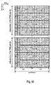
- Fig. 10 shows an exemplary division of two physical resource block pairs #m and #n that are considered to be part of a R-PDCCH region of a relay node into 8 control channel elements (CCEs).
- CCEs control channel elements
- the R-PDCCH information is mapped to a limited number of physical resource block pairs.
- CCE level interleaving among of R-PDCCH information of different relay nodes that have overlapping or identical R-PDCCH regions can be used.
- the offset may be considered to correspond to a certain number of subcarriers, i.e. a given offset bandwidth.
- the offset is chosen to be larger than or equal to the coherence bandwidth of the channel, such that the channel conditions within these two resource blocks are independent.
- Table 1 shows an overview of the number of resource elements per CCE in the example shown in Fig. 10 .
- Table 1 CCE number Number of RE for R-PDCCH information Number of RE for CRS Number of RE for DM-RS 1 22 3 8 2 26 3 4 3 26 3 4 4 22 3 8 5 22 3 8 6 26 3 4 7 26 3 4 8 22 3 8
- the amount of R-PDCCH information that can be conveyed in the respective CCEs is differing among the CCEs (each RE corresponds to one modulation symbol and thus to a corresponding number of coded bits depending on the modulation scheme level).
- different DCI formats of the R-PDCCH information may need to be defined so as to address the number of REs available for R-PDCCH information within the respective CCE(s) to which the R-PDCCH information is to be mapped. This latter option appears even more undesirable, since this would require a very complex interaction of the physical resource mapping functionality and coding functionality of the eNodeB.
- a control channel region for conveying control information, such as physical downlink control channel (PDCCH) information is suggested.
- a control channel region is defined/configured within sub-frames of a OFDM-based air interface of a mobile communications system, such as for example a 3GPP-based system like 3GPP LTE (Release 8) or LTE-A (Release 10).
- the control channel region is divided into control channel elements that have equal size irrespective of the presence of further cell-specific and/or UE-specific reference signals within the control channel region. This is achieved by dividing the control channel region in plural sub-control channel elements.
- the sub-channel elements are combined to control channel elements having equal size.
- the control channel region is divided in the frequency domain and/or time domain in a FDM respectively TDM fashion.
- Equal in size means that the number of resource elements available for the signaling of control information within the control channel elements is the same for all control channel elements of the control channel region. It is a matter of definition whether the reference signals that are located within the control channel elements are counted as part of the control channel elements or not, and the invention is applicable to both options. In the following examples, the reference symbols are not part of the sub-control channel elements and control channel elements for exemplary purposes only.
- the control channel region may span plural resource block pairs of the sub-frame, but may not necessarily "cover" the entire time domain resources of the sub-frame.
- sub-control channel elements of the same or different resource block pairs are combined to form the control channel elements.
- a distributed mapping of the control information may also be realized by mapping the control information to control channel elements of different resource block pairs, while each of the control channel elements themselves are formed by sub-control channel elements of one resource block pair only.
- the principles of this invention may be used for the signaling of physical control channel information from a base station (donor eNodeB) to relay nodes, from a base station (eNodeB) to mobile terminals (user equipments) and from a relay node to mobile terminals (user equipments). Accordingly, it will be referred to transmitting the control information from a "transmitting apparatus” (i.e. base station or relay node) to a “receiving apparatus” (i.e. relay node or mobile terminal) herein.
- Fig. 26 to Fig. 29 show different exemplary configuration of a control channel region within a sub-frame according to different embodiments of the invention.
- the sub-frame contains reference signals in some of the resource elements of the sub-frame.
- the reference signals may be provided in a regular pattern.
- the reference signals may be for example common reference signals (pertaining to all terminals/relay nodes of a radio cell), and/or terminal-specific reference signals, such as for example DM-RS for respective user equipments/relay nodes.
- the Fig. 26 to Fig. 29 exemplarily indicate the physical resource block pairs forming the control channel region to be adjacent to each other, this is not mandatory, but the individual resource block pairs may also be distributed in the frequency domain of the system bandwidth. Furthermore, it is also possible that there are adjacent and non-adjacent physical resource block pairs configured as the control channel region.
- Fig. 26 shows an example where the control region is configured within the shared data region (PDSCH region) of the sub-frame. This example may be especially applicable (but not restricted to) for the transmission of PDCCH information to relay nodes.
- the control channel region shown in Fig. 26 spans the entire N symb PDSCH OFDM symbols of the PDSCH region, i.e.
- N symb PDCCH may be for example dynamically configured, e.g. may correspond to the PCFICH value that is signaled within a sub-frame.
- N symb PDCCH may be configured on a semi-static or static basis as well.
- Fig. 27 shows another example where the control region is configured within the shared data region (PDSCH region) of the sub-frame.
- the control channel region is not spanning the entire PDSCH region, but the control channel spans the OFDM symbols of the sub-frame starting at symbol index n start R ⁇ PDCCH ⁇
- the N symb R ⁇ PDCCH symbols of the control region are the 5 th to the last (14 th ) OFDM symbol of the sub-frame
- n start R ⁇ PDCCH 5 ⁇ n start R ⁇ PDCCH may be for example configured on a semi-static basis using RRC signaling or is broadcast in the cell by means of system information.
- n start R ⁇ PDCCH could be static/predefined.
- n start R ⁇ PDCCH of the control region may be configured but also the end index n end R ⁇ PDCCH , so that in the time domain the control channel region spans the OFDM symbols n start R ⁇ PDCCH to n end R ⁇ PDCCH n start R ⁇ PDCCH ⁇ n end R ⁇ PDCCH .
- Both indices may be semi-statically or statically configured as described above.
- Fig. 26 and Fig. 27 may be useful for conveying physical downlink control channel information (e.g. uplink and downlink grants) to from a base station (donor eNodeB) to a relay node.
- physical downlink control channel information e.g. uplink and downlink grants
- Fig. 28 shows another exemplary configuration of a control channel region within a sub-frame according to another embodiment of the invention.
- the sub-frame has no control channel region configured, so that all OFDM symbols of the sub-frame may be considered part of the PDSCH region.
- the transmitting apparatus may configure control channel regions for the served receiving apparatus(es) (relay nodes or user equipments) that span the entire sub-frame in the time domain (e.g. all 2 ⁇ N symb OFDM symbols of the sub-frame).
- control channel region may also be configured to span only a certain range within the sub-frame, for example the first or second slot thereof.
- the individual extend of the control channel region may also be limited by the slot boundaries within the sub-frame.
- control channel region configurations in Fig. 28 and Fig. 29 may be configured on a dynamic, semi-static or static basis as outlined above.
- the starting index n start R ⁇ PDCCH and optionally the end index n end R ⁇ PDCCH may be configured.
- control channel structures according to several exemplary embodiments of the invention will be outlined. The embodiments are given with respect to a 3GPP-based mobile communications network using OFDMA in the downlink. Furthermore, the control channel region is referred to as R-PDCCH region in most of the examples below, as it is exemplarily assumed that the control channel structures discussed in the following is used for providing PDCCH information for a relay node from a donor eNodeB to a relay node.
- the examples are based on the sub-frame structure of a 3GPP LTE (Release 8) system as shown in Fig. 8 and Fig. 9 .
- 3GPP LTE-A Release 10
- the sub-frame structure of 3GPP LTE (Release 8) is reused on the aggregated component carriers.
- the sub-frame will span the aggregated component carriers of a user equipment, respectively relay node, i.e. the total number N RB DL of downlink resource blocks available within the sub-frame accounts for the total bandwidth of the aggregated component carriers.
- the sub-frame may span the entire bandwidth o the aggregated component carriers, the control channel region may still be defined per-component carrier.
- resource allocation by means of physical downlink control channel information may be performed for the individual component carriers rather than one aggregated component carrier.
- the use of sub-frame structures of a 3GPP LTE (Release 8) system is only exemplary and not limiting the invention to these structures.
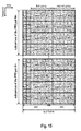
- Fig. 11 exemplifies a division of two physical resource block pairs #m and #n of a R-PDCCH region of a normal sub-frame into 16 sub-control channel elements (sub-CCEs) according to an exemplary embodiment of the invention.
- the approach depicted in Fig. 26 is adopted, i.e. the control channel region is spanning the PDSCH region of the sub-frame.
- the sub-frame is assumed to have a PDCCH region that is spanning the first two OFDM symbols - please note that the PDCCH region of the sub-frame may have N symb PDCCH ⁇ 0 , ... , 4 OFDM symbols in the time domain.
- the R-PDCCH channel region is spanning N RB R ⁇ PDCCH resource blocks in the frequency domain and N symb R ⁇ PDCCH OFDM symbols in the time domain.
- the control channel region may span multiple resource blocks (even and odd numbers) in the frequency domain.
- Fig. 11 exemplarily depicts the organization of sub-control channel elements for two physical resource block pairs. If there are more than two resource block pairs configured from the R-PDCCH region, the other resource block pairs are divided into sub-control channel elements in a similar fashion as shown in Fig. 11 .
- the R-PDCCH region of the exemplary embodiment of Fig. 11 is divided in the time domain into two groups of OFDM symbols (first group and second group).
- sub-CCE #i sub-control channel elements
- the boundary of the sub-control channel elements is defined by the slot boundaries of the sub-frame.
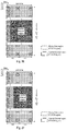
- Fig. 12 and Fig. 13 show exemplary combinations of pairs of the 16 sub-control channel elements (sub-CCEs) of Fig. 11 to form 8 control channel elements (CCEs) using a localized, respectively distributed mapping of the R-PDCCH information according to an embodiment of the invention.
- Fig. 2 and Table 2 show the combination of sub-control channel elements to obtain a localized mapping of control channel elements.
- Control Channel Element Sub-control channel element of first group Sub-control channel element of second group Resource block pairs utilized CCE #1 Sub-CCE #1 Sub-CCE #10 PRB pair #m CCE #2 Sub-CCE #2 Sub-CCE #9 PRB pair #m CCE #3 Sub-CCE #3 Sub-CCE #12 PRB pair #m CCE #4 Sub-CCE #4 Sub-CCE #11 PRB pair #m CCE #5 Sub-CCE #5 Sub-CCE #14 PRB pair #n CCE #6 Sub-CCE #6 Sub-CCE #13 PRB pair #n CCE #7 Sub-CCE #7 Sub-CCE #16 PRB pair #n CCE #8 Sub-CCE #8 Sub-CCE #15 PRB pair #n
- control channel elements are defined within one of the physical resource block pairs of the R-PDCCH region. Accordingly, also in case of using more then two physical resource block pairs such control channel elements of equal size can be built within a respective physical resource block pair.
- Table 3 below shows an alternative combination of sub-control channel elements shown in Fig. 11 to form control channel elements that allow for a localized mapping of the PDCCH information.
- Table 3 Control Channel Element
- Sub-control channel element of first group Sub-control channel element of second group Resource block pairs utilized CCE #1 Sub-CCE #1 Sub-CCE #11 PRB pair #m CCE #2 Sub-CCE #2 Sub-CCE #9 PRB pair #m CCE #3 Sub-CCE #3 Sub-CCE #12 PRB pair #m CCE #4 Sub-CCE #4 Sub-CCE #10 PRB pair #m CCE #5 Sub-CCE #5 Sub-CCE #15 PRB pair #n CCE #6 Sub-CCE #6 Sub-CCE #13 PRB pair #n CCE #7 Sub-CCE #7 Sub-CCE #16 PRB pair #n CCE #8 Sub-CCE #8 Sub-CCE #14 PRB pair #n
- the PDCCH information is either mapped to 1, 2, 4 or 8 control channel elements (i.e. the CCE aggregation size is 2 i ) .
- the CCE aggregation size is 2 i
- the also non-adjacent physical resource block pairs may form the R-PDCCH region, i.e. n ⁇ m ⁇ 1.
- a localized mapping may be understood as to refer to a mapping of the PDCCH information to resource block pairs that are within the coherence bandwidth of the channel (such that the channel conditions channel conditions within the two resource blocks are dependent from each other)
- a distributed mapping of the PDCCH information may be understood as to refer to a mapping of the PDCCH information to resource block pairs that are larger than or equal to the coherence bandwidth of the channel (such that the channel conditions channel conditions within the two resource blocks are independent from each other).
- Fig. 13 and Table 4 show the combination of sub-control channel elements to obtain a distributed mapping of control channel elements.
- Table 4 Control Channel Element Sub-control channel element of first group Sub-control channel elements of second group resource block pairs utilized CCE #1 Sub-CCE #1 Sub-CCE #14 PRB pairs #m & #n CCE #2 Sub-CCE #2 Sub-CCE #13 PRB pairs #m & #n CCE #3 Sub-CCE #3 Sub-CCE #16 PRB pairs #m & #n CCE #4 Sub-CCE #4 Sub-CCE #15 PRB pairs #m & #n CCE #5 Sub-CCE #5 Sub-CCE #10 PRB pairs #m & #n CCE #6 Sub-CCE #6 Sub-CCE #9 PRB pairs #m & #n CCE #7 Sub-CCE #7 Sub-CCE #12 PRB pairs #m & #n CCE #8 Sub-CCE #8 Sub-CCE #11 PRB pairs #m & #n
- control channel elements in a distributed mapping comprise respective pairs of sub-control channel elements from the first group and sub-control channel elements of the second group located in different physical resource block pairs. This way the control channel elements are always "distributed" across the physical resource block pairs.
- CRS and/or DM-RS is provided in the some predefined resource elements that are used by the receiving apparatus for channel estimation.
- CRS may for example be used when no beamforming is applied for the PDCCH information signaled in the R-PDCCH region.
- DM-RS may be used in a sub-frame for transmitting the beamforming is applied to the transmission of the PDCCH information in the R-PDCCH region on the air interface.
- the number of DM-RS signals provided in the physical resource block pairs, respectively the control channel elements may imply an upper limit on the number of receiving apparatus(es) to which the control channel elements within a R-PDCCH region can be assigned (assuming that the R-PDCCH regions of multiple transmitting apparatuses is overlapping or identical).
- the DM-RS layers are receiving apparatus specific and may be required for demodulation of the data signaled within the assigned physical resources on the downlink. Therefore, each receiving apparatus that is to receive data within a given physical resource block pair of the R-PDCCH region may require a own DM-RS to be present in the control channel element(s) assigned to which the PDCCH information is transmitted..
- each control channel element can be linked to one DM-RS layer for demodulation. Accordingly, the control channel elements in each physical resource block pair of the R-PDCCH region can be assigned up to four receiving apparatus(es).
- each physical resource block pair is divided into two control channel element (see for example Fig. 21 and Fig. 22 ) and each control channel element is linked to one DM-RS layer.
- the control channel elements in each physical resource block pair of the R-PDCCH region can be assigned to one or two receiving apparatus(es) only.
- each physical resource block pair is still divided into four control channel elements, but two control channel elements are linked to one DM-RS layer, respectively receiving apparatus. Accordingly, in this example the CCE aggregation level size may be restricted to be at least two control channel elements per receiving apparatus and physical resource block pair.
- the DM-RS layer may be chosen such that the number of DM-RS signals that are signaled in each control channel element is maximized.
- all control channel elements comprise resource elements with DM-RS signals of all four layers.
- Control channel elements #1, #2, #5 and #6 comprise four resource elements carrying DM-RS signals of layer 1 and 2 and two resource elements carrying DM-RS signals for layer 3 and 4. Accordingly, these control channel elements may be linked to DM-RS layer 1 or 2.
- Control channel elements #3, #4, #7 and #8 comprise two resource elements carrying DM-RS signals of layer 1 and 2 and four resource elements carrying DM-RS signals for layer 3 and 4, so that it is advantageous to link same to DM-RS layer 3 and 4.
- the transmitting apparatus ensures that the PDCCH information of a receiving apparatus is mapped to control channel element(s) linked to the DM-RS layer associated to the receiving apparatus, so that the number of DM-RS signals of the given DM-RS layer per control channel element can be maximized.
- mapping of the PDCCH information to the control channel elements in the R-PDCCH region depends on the number of control channel elements available therein and the CCE aggregation size. It may be exemplarily assumed that the PDCCH information for a receiving apparatus is either mapped to 1, 2, 4 or 8 control channel elements.
- CCE aggregation level 1 i.e. the PDCCH information of a receiving apparatus is mapped to one control channel element of the R-PDCCH region, and assuming a localized mapping of the PDCCH information to the control channel element (i.e. a localized search space for the receiving apparatus), the two sub-CCEs that form a control channel element are chosen from the same physical resource block pair.
- the distributed mapping of the PDCCH information to the control channel element i.e. a distributed search space for the receiving apparatus
- the two sub-CCEs that form a control channel element are chosen from different physical resource block pairs.
- both control channel elements are located in the same physical resource block pair.
- both control channel elements are located in different physical resource block pairs.
- the control channel elements may be consistently distributed in frequency domain.
- a distributed mapping of PDCCH information to the two control channel elements by the transmitting apparatus can be obtained by mapping the PDCCH information - for example - to CCE #1 and CCE #5.
- the control channel elements may be formed so that each control channel element is formed by sub-CCEs of multiple physical resource block pairs.
- each control channel element has a sub-CCE of physical resource block pair #m and a sub-CCE of physical resource block pair #n, so that a distributed mapping is obtained (irrespective of the actual CCE aggregation size).
- a localized or distributed mapping of the PDCCH information may be achieved by configuring the two physical resource block pairs either as adjacent physical resource block pairs or non-adjacent physical resource block pairs (as mentioned before, "adjacent" and “non-adjacent” may be defined relative to the coherence bandwidth of the channel).
- a localized and distributed mapping of the PDCCH information to the four control channel elements may be obtained in a similar fashion as described fro CCE aggregation level 2.
- the PDCCH information of a receiving apparatus is mapped to eight control channel elements of the R-PDCCH region, if one physical resource block pair is divided into two control channel elements, two physical resource block pairs will not be enough for transmitting the PDCCH information to the receiving apparatus.
- the transmitting apparatus may map only one half of the PDCCH information to the two physical resource block pairs.
- Another possibility is to configure four physical resource block pairs as the basic R-PDCCH region size.
- the two physical resource block pairs within the R-PDCCH region are sufficient to carry the PDCCH information.
- a localized or distributed mapping of the PDCCH information may be achieved by configuring the two physical resource block pairs either as adjacent physical resource block pairs or non-adjacent physical resource block pairs (as mentioned before, "adjacent" and “non-adjacent” may be defined relative to the coherence bandwidth of the channel).
- sub-control channel elements are their flexibility in combining same according to a known scheme. This may for example allow the transmitting apparatus to switch between localized and distributed mapping of the PDCCH information of the receiving apparatus to the R-PDCCH region. Furthermore, by a smart combination of the sub-control channel elements, also a simultaneous localized and distributed mapping can be realized, which may be advantage if plural receiving apparatuses have the same or overlapping R-PDCCH regions.
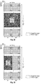
- Fig. 14 shows an exemplary combination of pairs of sub-control channel elements (sub-CCEs) of Fig. 11 to form eight control channel elements (CCEs) allowing fro a localized and a distributed mapping of the R-PDCCH information according to an embodiment of the invention.
- a smart combination of sub-CCEs may allow to re-use physical resource blocks for other purposes, e.g. PDSCH transmissions, if none of the control channel elements are used for mapping a R-PDCCH information.
- the control channel elements of Fig. 14 are obtained by a combination of sub-control channel element pairs as shown in Table 5.
- Table 5 Control Channel Element
- Sub-control channel element of first group Sub-control channel element of second group Resource block pairs utilized CCE #1 Sub-CCE #1 Sub-CCE #15 PRB pairs #m & #n CCE #2 Sub-CCE #2 Sub-CCE #16 PRB pairs #m & #n CCE #3 Sub-CCE #3 Sub-CCE #12 PRB pair #m CCE #4 Sub-CCE #4 Sub-CCE #11 PRB pair #m CCE #5 Sub-CCE #5 Sub-CCE #14 PRB pair #n CCE #6 Sub-CCE #6 Sub-CCE #13 PRB pair #n CCE #7 Sub-CCE #7 Sub-CCE #9 PRB pairs #m & #n CCE #8 Sub-CCE #8 Sub-CCE #10 PRB pairs #m & #n
- a donor eNodeB could assign two relay nodes the same R-PDCCH region and - assuming a CCE aggregation size of four - map the PDCCH information of one relay node in a localized fashion and the PDCCH information of the other relay node in a distributed fashion to the R-PDCCH resources.
- Fig. 15 exemplifies another division of two physical resource block pairs #m and #n of a R-PDCCH region into 16 sub-control channel elements (sub-CCEs) according to an exemplary embodiment of the invention.
- the example shown in Fig. 15 is similar to that of Fig. 11 described above, except for the sub-control elements not being divided in the time domain at the slot boundaries of the sub-frame. Instead, in this example, the N symb R ⁇ PDCCH OFDM symbols in the time domain are evenly distributed to the respective first group and second group of sub-control channel elements.
- Fig. 16 shows an exemplary combination of pairs of sub-control channel elements (sub-CCEs) of Fig. 15 to form 8 control channel elements (CCEs) using a localized mapping of the R-PDCCH information according to an embodiment of the invention.
- a distributed mapping of the R-PDCCH information may be obtained in a similar fashion as shown in Fig. 13 and as has been described above.
- the control channel elements may be formed as described with respect to Figs. 12 to 14 and Table 2 to Table 5 above.
- Fig. 11 to 16 While the example with reference to Fig. 11 to 16 have been exemplified using a normal sub-frame as known from 3GPP-LTE (Release 8), the same divisions and combinations as outlined with respect to Figs. 12 to 14 and Table 2 to Table 5 above may be used for a MBSFN sub-frame as shown in Fig. 9 .
- Fig. 17 exemplifies a division of two physical resource block pairs #m and #n of a R-PDCCH region of a MBSFN sub-frame into sub-control channel elements (sub-CCEs) according to an exemplary embodiment of the invention. Essentially, the difference to the normal division of the normal sub-frame as discussed with respect to Fig. 11 and Fig.
- the MBSFN sub-frame does not comprise common reference signals.
- the above outlined division of the R-PDCCH region in the frequency and time domain may also be applied in scenarios, where there is no control channel region provided in the first OFDM symbols of the sub-frame, as for example shown in Fig. 28 .
- a division of the control channel region in time domain and frequency domain has been used.
- Other embodiments encompass the division of the control channel region in frequency domain only.
- Fig. 18 exemplifies another division of two physical resource block pairs #m and #n of a R-PDCCH region into eight sub-control channel elements (sub-CCEs) according to an exemplary embodiment of the invention using a FDM approach.
- pairs of the sub-control channel elements #1 to #8 are combined to respective control channel elements, such that all four control channel elements resulting from this combination are equal in size.
- Fig. 19 and Fig. 20 show exemplary combinations of pairs of sub-control channel elements (sub-CCEs) of Fig. 18 to form the four resulting control channel elements (CCEs) facilitating a localized, respectively distributed.
- Table 6 exemplifies the sub-CCE combinations of the structure of the R-PDCCH region of Fig. 19 .
- the two sub-control channel elements of the same physical resource block pairs are combined respectively to obtain a localized mapping of the PDCCH information.
- Control Channel Element Sub-control channel element of first group Sub-control channel element of second group Resource block pairs utilized CCE #1 Sub-CCE #1 Sub-CCE #2 PRB pair #m CCE #2 Sub-CCE #3 Sub-CCE #4 PRB pair #m CCE #3 Sub-CCE #5 Sub-CCE #6 PRB pair #n CCE #4 Sub-CCE #7 Sub-CCE #8 PRB pair #n
- Table 7 exemplifies the sub-CCE combinations of the structure of the R-PDCCH region of Fig. 20 .
- the two sub-control channel elements of the different physical resource block pairs are combined respectively to obtain a distributed mapping of the PDCCH information.
- Table 7 Control Channel Element
- Sub-control channel element of first group Sub-control channel element of second group Resource block pairs utilized CCE #1 Sub-CCE #1 Sub-CCE #5 PRB pairs #m & #n CCE #2 Sub-CCE #2 Sub-CCE #6 PRB pairs #m & #n CCE #3 Sub-CCE #3 Sub-CCE #7 PRB pairs #m & #n CCE #4 Sub-CCE #4 Sub-CCE #8 PRB pairs #m & #n
- CCEs as shown in Fig. 19 and Table 6 that are located on different physical resource block pairs could be used for signaling the PDCCH information in a distributed fashion.
- the physical resource block pairs #m and #n may or may not be adjacent to each other within the frequency domain. Furthermore, in a likewise fashion, also R-PDCCH regions comparing more than two physical resource block pairs may be structured into control channel elements.
- Fig. 21 and 22 show exemplary combinations of pairs of sub-control channel elements (sub-CCEs) of Fig. 11 to form four control channel elements (CCEs) using a localized, respectively distributed mapping of the R-PDCCH information according to an embodiment of the invention.
- four sub-control channel elements are combined to form four control channel elements of equal size.
- Table 8 shows the sub-control channel elements that form the respective four control channel elements for the localized mapping of Fig. 21 .
- all control channel elements are formed by sub-control channel elements of the same physical resource block pair.
- Table 9 shows the sub-control channel elements that form the respective four control channel elements for the distributed mapping of Fig. 22 .
- the sub-control channel elements that form a respective control channel element are located on distinct physical resource block pairs.
- Table 9 Control Channel Element Sub-control channel element 1 of first group Sub-control channel element 2 of first group Sub-control channel element 3 of second group Sub-control channel element 4 of second group CCE #1 Sub-CCE #1 Sub-CCE #5 Sub-CCE #10 Sub-CCE #14 CCE #2 Sub-CCE #2 Sub-CCE #6 Sub-CCE #9 Sub-CCE #13 CCE #3 Sub-CCE #3 Sub-CCE #7 Sub-CCE #12 Sub-CCE #16 CCE #4 Sub-CCE #4 Sub-CCE #8 Sub-CCE #11 Sub-CCE #15
- Fig. 23 shows another division of a control channel region within a sub-frame in a FDM fashion according to a further exemplary embodiment of the invention.
- the sub-frame do not contain a PDCCH region within the firsts OFDM symbols of the sub-frame.
- a PDCCH region carrying the PDCCH information for the receiving apparatus is assigned to the receiving apparatus (e.g. a user equipment or a relay node) by the transmitting apparatus (e.g. base station or relay node).
- the PDCCH regions of the receiving apparatus(es) within a radio cell controlled by the transmitting apparatus may overlap or may even be identical.
- the PDDCH region may be considered a search space in which the respective receiving apparatus is expecting to receive the control signaling (e.g. downlink and/or uplink resource assignments) from the transmitting apparatus.
- the PDCCH region is spanning the OFDM symbols of the first slot of the sub-frame.
- N symb R ⁇ PDCCH N symb in this exemplary embodiment.
- pairs of the sub-control channel elements #1 to #8 are combined to respective control channel elements, such that all four control channel elements resulting from this combination are equal in size.
- the transmitting apparatus may be either a base station (e.g. a eNodeB) or a relay node.
- the receiving apparatus may be a relay node or a user equipment.
- the transmitting apparatus may of course serve more than one receiving apparatus in its coverage area and comprises a scheduling function for assigning uplink or downlink resources to the transmitting apparatus(es) by means of signaling PDCCH information on the (R-)PDCCH region.
- the transmitting assigning to a receiving apparatus a control channel region ((R-)PDCCH region) within sub-frames for signaling PDCCH information to the receiving apparatus.
- the (R-)PDCCH region is structured into control channel elements according to one of the various embodiments of the invention discussed above.
- the physical resources of the (R-)PDCCH region may be configured on dynamically or semi-statically or may be predefined.
- the transmitting apparatus may use radio resource control signaling, i.e. may send the parameters that describe the time and frequency resource of the (R-)PDCCH region to the receiving apparatus by means of an RRC signaling message.
- the (R-)PDCCH region may also be configured by the transmitting apparatus by means of system information broadcast in the radio cell of the transmitting apparatus.
- the configuration information may be sent in one of the system information blocks broadcast by the transmitting apparatus.
- Another possibility is to statically define the R-)PDCCH region, for example by pre-defining it in a specification.
- the configuration information made available to the receiving apparatus include an indication of the physical resource block pairs that define the (R-)PDCCH region. If the extend of the (R-)PDCCH region in the time domain is not predefined or implicit from sub-frame boundaries or other parameters such as the PCFICH value, the configuration information may further include an indication of the OFDM symbols of the sub-frame that define the (R-)PDCCH region in the time domain.
- the transmitting apparatus may indicate in the configuration information the symbol index n start R ⁇ PDCCH of the OFDM symbol at which the first symbol of the (R-)PDCCH region.
- the configuration information may also comprise a symbol index n end R ⁇ PDCCH for indicating the last symbol of the (R-)PDCCH region or the size of (R-)PDCCH region in terms of number of OFDM symbols.
- the transmitting apparatus generates a sub-frame to be sent in the downlink.
- the sub-frame may comprise control information and user data of multiple receiving apparatuses.
- the sub-frame as such spans all downlink component carriers available to the base station, but is logically divided into plural OFDM symbols in the time domain on respective component carriers in the frequency domain.
- the component carriers in the downlink span a certain range of sub-bands (subcarriers) that define the bandwidth of the respective component carrier.
- the sub-frame structure may be as such structured as shown in Fig. 8 or Fig. 9 and comprises several reference signals that are transmitted on respective resource elements in a pre-determined pattern.
- the transmitting apparatus generates PDCCH information for one or more receiving apparatuses.
- the PDCCH information may be provided in form of a know downlink control information (DCI) format.
- the transmitting apparatus maps the PDCCH information for transmission to one or more control channel elements in the (R-)PDCCH region that is configured for a respective receiving apparatus within a sub-frame on the downlink.
- the transmitting apparatus may use a distributed or localized mapping scheme for mapping the PDCCH information to the (R-)PDCCH region using one of the various (R-)PDCCH region structures as outlined above.
- the PDCCH information is mapped to 2 i of the control channel elements defined in the (R-)PDCCH region, wherein i ⁇ ⁇ 0,1,2,3 ⁇ or i ⁇ ⁇ 0,1,2,3,4 ⁇ .
- a receiving apparatus-specific (i.e. UE-specific or relay node-specific) RNTI Radio Network Terminal Identifier
- RNTI Radio Network Terminal Identifier
- the receiving apparatus detects the PDCCH information to be destined to it by checking whether the CRC on the decoded PDCCH information using the "unmasked" CRC (i.e. after removing the masking using the RNTI) is successful. Please note that the masking of the CRC code is performed by scrambling the CRC with the RNTI.
- the CRC of coded PDCCH information is scrambled/masked with a respective RNTI of the transmitting apparatus and the coded PDCCH information and the masked CRC code (CRC attachment) is mapped to the CCEs within the (R-)PDCCH region on the downlink as outlined in one of the different embodiments of the (R-)PDCCH region structure above.
- the transmitting apparatus transmits the sub-frame on the downlink.
- the receiving apparatuses attempt to detect the control information in their assigned (R-)PDCCH region using so-called “blind decoding”. This means that there is no associated control signaling that would indicate the CCE aggregation size or modulation and coding scheme for the PDCCH information signaled in the downlink, but the user equipments/relay nodes test for all possible combinations of CCE aggregation sizes and modulation and coding schemes, and confirms that successful decoding of a PDCCH information based on the RNTI that is used to mask the CRC field that is attached to the PDCCH information.
- the receiving apparatuses may be assumed to perform a blind detection on a set of (R-)PDCCH candidates for the PDCCH information in every non-DRX sub-frame, where blind detection implies attempting to decode each of the (R-)PDCCH candidate in the set according to some set of the monitored (R-)PDCCH formats (Downlink Control Information (DCI) formats).
- the set of (R-)PDCCH candidates to monitor may be defined in terms of search spaces, where a search space at each CCE aggregation level L ⁇ ⁇ 1,2,4,8 ⁇ is defined by a set of PDCCH candidates.
- search spaces may be particularly useful in situations where multiple receiving apparatuses share a common (R-)PDCCH region of larger extend, so that it may be desirable to limit the search for PDCCH information by the respective receiving apparatuses to respective sub-regions (i.e. the search space) to thereby reduce the number of blind decoding attempts.
- the receiving apparatuses may be allocated to one or more search spaces in which they expect their PDCCH information.
- two types of search spaces may be defined: one is a localized search space and the other is distributed a search spaces.
- localized search space at each CCE aggregation level, the CCEs composing the PDCCH candidates are more localized in frequency domain.
- distributed search space at each aggregation level, the CCEs composing the PDCCH candidates are distributed in frequency domain.
- a receiving apparatus may be configured to monitor a localized search space only, a distributed search space only or a localized and distributed search space simultaneously. Which search space(s) are to be monitored by a respective receiving apparatus may be for example configured by the transmitting apparatus by means of RRC signaling,
- the receiving apparatus blind decodes the payload size of the (R-)PDCCH message and uses its RNTI to descramble the CRC. Based on the descrambled CRC information, the receiving apparatus determines whether the message payload (i.e. decoded PDCCH information) has been successfully decoded and is destined to the receiving apparatus.
- the message payload i.e. decoded PDCCH information
- the PDCCH information for the receiving apparatus may for example contain an uplink and/or downlink resource assignment for the receiving apparatus.
- the resource assignments for uplink and downlink indicate the assigned physical resources on downlink, respectively uplink, in terms of physical resource blocks, the modulation and coding scheme of the transport block to be received/transmitted on the indicated downlink/uplink resources, and the transport block size.
- further HARQ related information such as the new data indicator (NDI) and/or the HARQ process identifier may also be included in the resource assignments.
- the resource assignments may also comprise a carrier identifier field (CIF) that indicates the downlink respectively uplink component carrier on which the physical resources are assigned.
- CIF carrier identifier field
- the resources for the transmission of the transport block may be transmitted on the same downlink sub-frame as the downlink resource assignment. Accordingly, the receiving apparatus will try to receive and decode the downlink transport block.
- the receiving apparatus In case of an uplink resource assignment, the receiving apparatus generates a transport block according to the parameters (modulation and coding scheme and transport block size) and transmits the transport block on the assigned uplink resources.
- Another embodiment of the invention is related to the allocation of the physical resource block pairs that belong to the (R-)PDCCH region to the receiving apparatus.
- it is proposed to use an allocation method similar to the (Distributed Virtual Resource Block) DVRB allocation method known from 3GPP LTE (Release 8).
- 3GPP LTE Release 8
- four types of resource allocation are used for allocation physical resources in the PDSCH region of sub-frame.
- One of these four allocation types is the DVRB allocation.
- DVRB allocation is advantageous for distributed mapping of small data.
- DVRB allocation a number of contiguous Distributed Virtual Resource Blocks (DVRBs) is allocated to the scheduled receiving apparatus.
- the DVRBs are identified by their indices.
- the DVRBs are mapped to "real" physical resource blocks according to a given mapping rule.
- the (R-)PDCCH region resources may also be indicated as virtual resource blocks that are mapped to physical resource blocks for transmission.
- the mapping follows some rules so that DVRB index is distributed across the bandwidth and achieve 4 th order diversity.
- it may be advantageous to allocated (R-)PDCCH region on distributed physical resource blocks. DVRB allocation for (R-)PDCCH region may ensure that the resource blocks within the (R-)PDCCH region are distributed in the frequency domain.
- Another embodiment of the invention relates to the implementation of the above described various embodiments using hardware and software. It is recognized that the various embodiments of the invention may be implemented or performed using computing devices (processors) that are suitably controlled by executable instructions that cause the computing device to perform the functions according to the different embodiments of the invention described herein.
- the transmitting apparatus's scheduling function, the signaling mechanisms for configuring the (R-)PDCCH region, the sub-frame generation, the mapping of PDCCH information to appropriate OFDM symbols of the (R-)PDCCH region in the sub-frame according to given mapping rules, etc. may be for example implemented in hardware and/or software.
- the processing of the received sub-frames at the receiving apparatuses may at least partly implemented in hardware and/or software.
- a computing device or processor may for example be general purpose processors, digital signal processors (DIP), application specific integrated circuits (ASICS), field programmable gate arrays (FAGAN) or other programmable logic devices, etc.
- DIP digital signal processor
- ASICS application specific integrated circuits
- FAGAN field programmable gate arrays
- the various embodiments of the invention may also be performed or embodied by a combination of these devices.
- the various embodiments of the invention may also be implemented by means of software modules, which are executed by a processor or directly in hardware. Also a combination of software modules and a hardware implementation may be possible.
- the software modules may be stored on any kind of computer-readable storage media, for example RAM, EPROM, EPSOM, flash memory, registers, hard disks, CD-ROM, DVD, etc.
Landscapes
- Engineering & Computer Science (AREA)
- Signal Processing (AREA)
- Computer Networks & Wireless Communication (AREA)
- Mobile Radio Communication Systems (AREA)
- Radio Transmission System (AREA)
Priority Applications (1)
| Application Number | Priority Date | Filing Date | Title |
|---|---|---|---|
| EP16151461.7A EP3029876B1 (fr) | 2010-04-13 | 2011-02-25 | Cartographie d'informations de controle pour controler des elements de canaux |
Applications Claiming Priority (4)
| Application Number | Priority Date | Filing Date | Title |
|---|---|---|---|
| EP10003913A EP2378703A1 (fr) | 2010-04-13 | 2010-04-13 | Cartographie d'informations de contrôle pour contrôler des éléments de canaux |
| EP15151107.8A EP2866375B1 (fr) | 2010-04-13 | 2011-02-25 | Mappage d'informations de commande sur des éléments de canal de commande |
| EP16151461.7A EP3029876B1 (fr) | 2010-04-13 | 2011-02-25 | Cartographie d'informations de controle pour controler des elements de canaux |
| EP11705823.0A EP2559191B1 (fr) | 2010-04-13 | 2011-02-25 | Mappage d'informations de commande sur des éléments de canal de commande |
Related Parent Applications (3)
| Application Number | Title | Priority Date | Filing Date |
|---|---|---|---|
| EP15151107.8A Division EP2866375B1 (fr) | 2010-04-13 | 2011-02-25 | Mappage d'informations de commande sur des éléments de canal de commande |
| EP15151107.8A Division-Into EP2866375B1 (fr) | 2010-04-13 | 2011-02-25 | Mappage d'informations de commande sur des éléments de canal de commande |
| EP11705823.0A Division EP2559191B1 (fr) | 2010-04-13 | 2011-02-25 | Mappage d'informations de commande sur des éléments de canal de commande |
Publications (2)
| Publication Number | Publication Date |
|---|---|
| EP3029876A1 true EP3029876A1 (fr) | 2016-06-08 |
| EP3029876B1 EP3029876B1 (fr) | 2017-08-02 |
Family
ID=42735400
Family Applications (4)
| Application Number | Title | Priority Date | Filing Date |
|---|---|---|---|
| EP10003913A Withdrawn EP2378703A1 (fr) | 2010-04-13 | 2010-04-13 | Cartographie d'informations de contrôle pour contrôler des éléments de canaux |
| EP15151107.8A Active EP2866375B1 (fr) | 2010-04-13 | 2011-02-25 | Mappage d'informations de commande sur des éléments de canal de commande |
| EP11705823.0A Active EP2559191B1 (fr) | 2010-04-13 | 2011-02-25 | Mappage d'informations de commande sur des éléments de canal de commande |
| EP16151461.7A Active EP3029876B1 (fr) | 2010-04-13 | 2011-02-25 | Cartographie d'informations de controle pour controler des elements de canaux |
Family Applications Before (3)
| Application Number | Title | Priority Date | Filing Date |
|---|---|---|---|
| EP10003913A Withdrawn EP2378703A1 (fr) | 2010-04-13 | 2010-04-13 | Cartographie d'informations de contrôle pour contrôler des éléments de canaux |
| EP15151107.8A Active EP2866375B1 (fr) | 2010-04-13 | 2011-02-25 | Mappage d'informations de commande sur des éléments de canal de commande |
| EP11705823.0A Active EP2559191B1 (fr) | 2010-04-13 | 2011-02-25 | Mappage d'informations de commande sur des éléments de canal de commande |
Country Status (4)
| Country | Link |
|---|---|
| US (6) | US9131490B2 (fr) |
| EP (4) | EP2378703A1 (fr) |
| JP (3) | JP5722430B2 (fr) |
| WO (1) | WO2011128013A1 (fr) |
Cited By (3)
| Publication number | Priority date | Publication date | Assignee | Title |
|---|---|---|---|---|
| CN107888352A (zh) * | 2016-09-29 | 2018-04-06 | 华为技术有限公司 | 参考信号的处理方法、用户设备和基站 |
| CN108259147A (zh) * | 2016-12-29 | 2018-07-06 | 华为技术有限公司 | Ofdm符号的发送、接收方法及装置 |
| TWI676380B (zh) * | 2017-01-27 | 2019-11-01 | 大陸商廣東歐珀移動通信有限公司 | 傳輸信號的方法及設備 |
Families Citing this family (89)
| Publication number | Priority date | Publication date | Assignee | Title |
|---|---|---|---|---|
| KR20110038994A (ko) * | 2009-10-09 | 2011-04-15 | 삼성전자주식회사 | 다중 안테나를 이용하는 무선 통신 시스템에서 다중 사용자 제어 채널 송수신 방법 및 장치 |
| EP2378703A1 (fr) * | 2010-04-13 | 2011-10-19 | Panasonic Corporation | Cartographie d'informations de contrôle pour contrôler des éléments de canaux |
| JP5784152B2 (ja) | 2011-02-11 | 2015-09-24 | インターデイジタル パテント ホールディングス インコーポレイテッド | 拡張された制御チャネルのシステムおよび方法 |
| US9277551B2 (en) * | 2011-02-15 | 2016-03-01 | Lg Electronics Inc. | Hybrid automatic repeat request (HARQ) method and device in a cooperative terminal communication system |
| US9363805B2 (en) * | 2011-04-03 | 2016-06-07 | Lg Electronics Inc. | Method and apparatus for transmitting/receiving downlink control channel in wireless communication system |
| EP4221048A1 (fr) | 2011-05-02 | 2023-08-02 | BlackBerry Limited | Procédés et systèmes de communication sans fil avec têtes radio distantes |
| US20120282936A1 (en) * | 2011-05-02 | 2012-11-08 | Research In Motion Limited | Methods of PDCCH Capacity Enhancement in LTE Systems |
| US9014020B2 (en) | 2011-05-02 | 2015-04-21 | Blackberry Limited | Methods and systems of wireless communication with remote radio heads |
| WO2012150310A1 (fr) * | 2011-05-03 | 2012-11-08 | Telefonaktiebolaget L M Ericsson (Publ) | Surveillance de canal de commande basée sur la zone de recherche |
| WO2012154003A2 (fr) * | 2011-05-11 | 2012-11-15 | 엘지전자 주식회사 | Procédé de transmission de signal au moyen d'une pluralité de mots codés dans un système de communication sans fil et extrémité de transmission associée |
| CN102833857A (zh) * | 2011-06-17 | 2012-12-19 | 中兴通讯股份有限公司 | 一种上行数据发送调度方法、系统及装置 |
| KR101943821B1 (ko) * | 2011-06-21 | 2019-01-31 | 한국전자통신연구원 | 무선 통신 시스템에서 제어채널 송수신 방법 |
| CN107465491B (zh) * | 2011-06-27 | 2021-02-12 | 华为技术有限公司 | 确定控制信道资源的方法和用户设备 |
| EP2731283B1 (fr) * | 2011-06-30 | 2018-10-10 | LG Electronics Inc. | Procédé et appareil pour attribuer un canal de commande de liaison descendante dans un système de communication sans fil |
| CN102904669B (zh) * | 2011-07-29 | 2016-05-18 | 上海贝尔股份有限公司 | 预编码物理下行控制信道参考信号及盲译码方法和装置 |
| WO2013022261A2 (fr) * | 2011-08-11 | 2013-02-14 | Samsung Electronics Co., Ltd. | Extension de canaux de commande de liaison descendante physiques dans un système de communication |
| JP5883930B2 (ja) | 2011-08-19 | 2016-03-15 | エルジー エレクトロニクス インコーポレイティド | 無線通信システムにおいて基地局が下りリンク制御チャネルを送信する方法及びそのための装置 |
| US9008035B2 (en) * | 2011-09-29 | 2015-04-14 | Futurewei Technologies, Inc. | Wireless communication control channel systems and methods |
| US9402264B2 (en) * | 2011-09-30 | 2016-07-26 | Intel Corporation | Methods to transport internet traffic over multiple wireless networks simultaneously |
| WO2013055038A1 (fr) * | 2011-10-13 | 2013-04-18 | Lg Electronics Inc. | Procédé et appareil d'attribution de ressources dans un système de communication sans fil |
| US9544107B2 (en) | 2011-10-26 | 2017-01-10 | Lg Electronics Inc. | Method and apparatus for allocating control channel in wireless communication system |
| WO2013062205A1 (fr) * | 2011-10-27 | 2013-05-02 | 엘지전자 주식회사 | Procédé et dispositif permettant à une station de base dans un système de communication sans fil de transmettre un signal de référence spécifique de terminal destiné à un canal de contrôle |
| CN105846984B (zh) * | 2011-11-04 | 2019-04-23 | 华为技术有限公司 | 接收和发送控制信道的方法、用户设备和基站 |
| EP2590350A1 (fr) | 2011-11-07 | 2013-05-08 | Panasonic Corporation | Chevauchement PDCCH amélioré dans la région PDCCH |
| CN102404076B (zh) * | 2011-11-07 | 2014-12-10 | 电信科学技术研究院 | 信息发送及盲检方法和设备 |
| EP2779495B1 (fr) | 2011-11-13 | 2021-03-24 | LG Electronics Inc. | Procédé et appareil de transmission d'informations de commande dans un système de communication sans fil |
| KR20130054180A (ko) | 2011-11-14 | 2013-05-24 | 삼성전자주식회사 | 무선 통신 시스템에서 제어 채널 전송을 위한 레퍼런스 시그널링 리소스 할당 방법 |
| JP2015507858A (ja) * | 2011-12-02 | 2015-03-12 | エルジー エレクトロニクス インコーポレイティド | 無線通信システムにおいて端末がダウンリンク制御チャネルを受信する方法及びそのための装置 |
| KR101603457B1 (ko) | 2011-12-06 | 2016-03-14 | 엘지전자 주식회사 | 무선 통신 시스템에서 참조 신호를 전송하는 방법 및 장치 |
| WO2013085335A1 (fr) * | 2011-12-07 | 2013-06-13 | 엘지전자 주식회사 | Procédé et appareil pour émettre/recevoir un canal de commande descendant dans un système de communication sans fil |
| GB2497734B (en) | 2011-12-16 | 2014-11-26 | Broadcom Corp | Method and apparatus for mapping to an uplink resource |
| KR101710671B1 (ko) * | 2011-12-23 | 2017-02-28 | 후지쯔 가부시끼가이샤 | 물리적 다운링크 제어 채널의 자원 매핑 방법 및 장치 |
| JP5967218B2 (ja) * | 2011-12-28 | 2016-08-10 | 富士通株式会社 | 下り制御チャネルのサーチ空間のマッピング方法及び装置 |
| CN108234103B (zh) * | 2012-01-11 | 2023-06-20 | 三星电子株式会社 | 用于无线通信的方法和装置 |
| US9191945B2 (en) | 2012-01-18 | 2015-11-17 | Lg Electronics Inc. | Method and apparatus for enhanced control channel-based operation in wireless communication system |
| EP2807784A1 (fr) * | 2012-01-27 | 2014-12-03 | Interdigital Patent Holdings, Inc. | Systèmes et/ou procédés d'établissement d'un canal epdcch dans un réseau basé sur de multiples porteuses et/ou quasi-assemblé |
| KR102023009B1 (ko) | 2012-01-31 | 2019-09-19 | 엘지전자 주식회사 | 무선 통신 시스템에서 하향링크 제어 채널을 위한 참조 신호 안테나 포트 결정 방법 및 이를 위한 장치 |
| US9252861B2 (en) * | 2012-02-16 | 2016-02-02 | Panasonic Intellectual Property Corporation Of America | Receiver device, transmitter device, reception method, and transmission method |
| EP4007196B1 (fr) * | 2012-03-05 | 2023-09-20 | Samsung Electronics Co., Ltd. | Transmission de signal harq-ack en réponse à la détection de type de canal de commande en cas de multiples types de canal de commande |
| CN104221437B (zh) * | 2012-03-16 | 2018-04-13 | 联发科技股份有限公司 | Ofdm/ofdma系统中增强物理下行链路控制信道的物理结构以及参考信号利用 |
| KR20130111999A (ko) * | 2012-04-02 | 2013-10-11 | 엘지전자 주식회사 | 무선 통신 시스템에서 분산적 타입 하향링크 제어 채널의 검색 영역을 위하여 자원 블록을 구성하는 방법 및 이를 위한 장치 |
| KR20130124004A (ko) * | 2012-05-04 | 2013-11-13 | 삼성전자주식회사 | 밀리미터 전파 통신 시스템에서 전송기법에 따른 자원할당 방법 및 장치 |
| WO2013183975A1 (fr) * | 2012-06-08 | 2013-12-12 | 엘지전자 주식회사 | Procédé et dispositif d'émission de signal de commande de liaison montante dans un système de communication sans fil |
| US9713134B2 (en) * | 2012-06-25 | 2017-07-18 | Lg Electronics Inc. | Method and device for allocating resource for downlink control channel in wireless communication system, and apparatus therefor |
| MX2014000701A (es) | 2012-07-25 | 2014-03-06 | Panasonic Corp | Aparato de estacion base, aparato terminal, metodo de transmision y metodo de recepcion. |
| GB2504544A (en) * | 2012-08-02 | 2014-02-05 | Nec Corp | Resource allocation signalling within an enhanced Physical Downlink Control Channel (ePDCCH) |
| JP6139686B2 (ja) * | 2012-09-21 | 2017-05-31 | ▲ホア▼▲ウェイ▼技術有限公司Huawei Technologies Co.,Ltd. | ダウンリンク制御情報を送信するための方法、ネットワーク側装置、およびユーザ機器 |
| WO2014047850A1 (fr) | 2012-09-27 | 2014-04-03 | 华为技术有限公司 | Procédé et dispositif pour attribuer des canaux de commande candidats |
| US9307521B2 (en) * | 2012-11-01 | 2016-04-05 | Samsung Electronics Co., Ltd. | Transmission scheme and quasi co-location assumption of antenna ports for PDSCH of transmission mode 10 for LTE advanced |
| CN103813468A (zh) * | 2012-11-09 | 2014-05-21 | 北京三星通信技术研究有限公司 | 一种传输下行数据的方法和设备 |
| US10085247B2 (en) * | 2013-03-08 | 2018-09-25 | Sharp Kabushiki Kaisha | Physical control channel monitoring |
| US20160020882A1 (en) * | 2013-03-18 | 2016-01-21 | Sharp Kabushiki Kaisha | Base station, terminal, communication system, communication method, and integrated circuit |
| JP6217745B2 (ja) * | 2013-03-22 | 2017-10-25 | 富士通株式会社 | 無線通信システム、無線通信方法、受信装置および送信装置 |
| KR102025715B1 (ko) * | 2013-06-26 | 2019-11-26 | 후아웨이 테크놀러지 컴퍼니 리미티드 | 참조 신호를 전송하는 방법 및 장치 |
| EP3061202B1 (fr) | 2013-10-31 | 2018-12-12 | Sony Corporation | Élément de réseau, et procédé de communication utilisant une pluralité de modules canaux de commande |
| EP3075162A4 (fr) | 2013-11-29 | 2017-07-26 | LG Electronics Inc. | Appareil d'émission de signaux de diffusion, appareil de réception de signaux de diffusion, procédé d'émission de signaux de diffusion et procédé de réception de signaux de diffusion |
| US9699048B2 (en) | 2014-02-13 | 2017-07-04 | Samsung Electronics Co., Ltd. | Computing system with channel quality mechanism and method of operation thereof |
| US10063340B2 (en) * | 2014-11-25 | 2018-08-28 | Nokia Solutions And Networks Oy | Dynamic resource adaptation |
| CN105846974B (zh) * | 2015-01-12 | 2020-02-18 | 中国移动通信集团上海有限公司 | 一种配置控制信道资源的方法及设备 |
| EP3254488B1 (fr) * | 2015-02-06 | 2021-07-07 | Panasonic Intellectual Property Corporation of America | Procédé de communication sans fil, enodb et équipement d'utilisateur |
| WO2016143967A1 (fr) * | 2015-03-12 | 2016-09-15 | 엘지전자 주식회사 | Procédé permettant d'agencer une structure de trames d'un intervalle de temps de transmission court flexible en fonction d'une modification dans une région de commande, et dispositif utilisant ce procédé |
| CN107431588B (zh) | 2015-03-20 | 2020-08-07 | Lg 电子株式会社 | 用于短tti的时间频率资源的分配方法及其设备 |
| CN106302287B (zh) * | 2015-05-29 | 2019-07-16 | 苏州简约纳电子有限公司 | 数据通信方法 |
| US10868645B2 (en) * | 2015-11-06 | 2020-12-15 | Huawei Technologies Co., Ltd. | Method and base station for transmitting downlink data |
| WO2017099526A1 (fr) * | 2015-12-11 | 2017-06-15 | 엘지전자 주식회사 | Procédé de réception de canal de liaison descendante et équipement utilisateur, et procédé de transmission de canal de liaison descendante et station de base |
| CN113507354A (zh) * | 2016-01-11 | 2021-10-15 | 苹果公司 | 用于IoT控制信道的装置和方法 |
| EP3414960A4 (fr) * | 2016-03-30 | 2019-10-23 | Nec Corporation | Procédés et appareils pour émettre et recevoir des signaux de référence |
| CN107370683B (zh) * | 2016-05-13 | 2020-06-26 | 电信科学技术研究院 | 一种数据传输方法、终端及基站 |
| US10660081B2 (en) | 2016-06-01 | 2020-05-19 | Lg Electronics Inc. | Downlink signal reception method and user equipment, and downlink signal transmission method and base station |
| MX2018014854A (es) * | 2016-06-20 | 2019-05-06 | Ericsson Telefon Ab L M | Red de transmision flexible. |
| BR112019006412A2 (pt) | 2016-09-30 | 2019-09-10 | Huawei Tech Co Ltd | método de transmissão do canal de controle, dispositivo de rede e dispositivo terminal |
| CN108023619B (zh) * | 2016-11-03 | 2023-09-01 | 华为技术有限公司 | 一种预编码配置方法、设备及系统 |
| US11290994B2 (en) * | 2016-11-03 | 2022-03-29 | Guangdong Oppo Mobile Telecommunications Corp., Ltd. | Signal transmission method, terminal device, and network device |
| WO2018084799A1 (fr) * | 2016-11-04 | 2018-05-11 | Telefonaktiebolaget Lm Ericsson (Publ) | Utilisation de signaux de référence de mobilité pour effectuer une surveillance de liaison radio dans un système à base de faisceau |
| EP4096139A1 (fr) | 2016-11-04 | 2022-11-30 | Telefonaktiebolaget LM Ericsson (publ) | Améliorations apportées à des signaux de référence de mobilité pour une surveillance de liaison radio dans un système basé sur un faisceau |
| MX2019005229A (es) | 2016-11-04 | 2019-08-05 | Ericsson Telefon Ab L M | Reutilizacion de señales de referencia de movilidad para llevar a cabo monitoreo de enlace de radio en un sistema basado en haces. |
| WO2018112698A1 (fr) * | 2016-12-19 | 2018-06-28 | 广东欧珀移动通信有限公司 | Procédé de transmission de signal, dispositif de réseau et dispositif terminal |
| US11665691B2 (en) * | 2017-01-05 | 2023-05-30 | Sony Corporation | Communications devices and methods |
| US11166264B2 (en) * | 2017-02-06 | 2021-11-02 | Mediatek Inc. | Multiplexing of short physical downlink control channel and data in mobile communications |
| CN108631979B (zh) * | 2017-03-24 | 2022-09-06 | 中兴通讯股份有限公司 | 一种解调导频的处理方法及装置 |
| CN108923896B (zh) | 2017-04-19 | 2021-03-26 | 上海朗帛通信技术有限公司 | 一种被用于寻呼的用户设备、基站中的方法和装置 |
| US11038646B2 (en) * | 2017-06-26 | 2021-06-15 | Qualcomm Incorporated | Techniques and apparatuses for shared reference signal transmission and reception |
| RU2744725C1 (ru) | 2017-08-10 | 2021-03-15 | Гуандун Оппо Мобайл Телекоммьюникейшнс Корп., Лтд. | Способ, сетевое устройство и оконечное устройство беспроводной связи |
| CN111344983B (zh) * | 2017-11-13 | 2022-06-07 | Lg电子株式会社 | 在无线通信系统中发送和接收数据的方法及其装置 |
| EP3823367A4 (fr) * | 2018-08-06 | 2021-07-28 | Huawei Technologies Co., Ltd. | Procédé et dispositif pour réduire un brouillage dans le même canal, et station de base |
| WO2020042180A1 (fr) * | 2018-08-31 | 2020-03-05 | 华为技术有限公司 | Procédé de réception et de transmission de signal de référence, et dispositif et système |
| US11729786B2 (en) * | 2020-01-07 | 2023-08-15 | Qualcomm Incorporated | Physical downlink control channel for low complexity operation |
| US11523377B2 (en) * | 2020-02-14 | 2022-12-06 | T-Mobile Usa, Inc. | LTE resource allocation controller |
| WO2021184170A1 (fr) * | 2020-03-16 | 2021-09-23 | 北京小米移动软件有限公司 | Procédé et appareil de transmission de données, dispositif de communication, et support d'enregistrement |
Family Cites Families (13)
| Publication number | Priority date | Publication date | Assignee | Title |
|---|---|---|---|---|
| KR20070006911A (ko) * | 2004-04-27 | 2007-01-11 | 닛산 가가쿠 고교 가부시키 가이샤 | 피라졸술포닐우레아화합물 및 제초제 |
| US9065714B2 (en) * | 2007-01-10 | 2015-06-23 | Qualcomm Incorporated | Transmission of information using cyclically shifted sequences |
| WO2008133415A1 (fr) * | 2007-04-27 | 2008-11-06 | Lg Electronics Inc. | Méthode de transmission d'un canal de contrôle de liaison descendante dans un système de communication mobile et méthode de mise en correspondance du canal de contrôle avec des ressources physiques en utilisant un entrelaceur de blocs dans un système de communication mobile |
| BRPI0810979A2 (pt) * | 2007-04-27 | 2015-07-21 | Lg Electronics Inc | Método para transmissão de canal de controle em sistema de comunicação móvel |
| KR101416994B1 (ko) * | 2007-06-26 | 2014-07-08 | 삼성전자주식회사 | 무선 통신 시스템에서 주파수 자원 할당 장치 및 방법 |
| KR101376233B1 (ko) | 2007-10-02 | 2014-03-21 | 삼성전자주식회사 | 주파수 분할 다중 접속 방식의 시스템에서 제어 채널의자원 할당 장치 및 방법 |
| KR100913473B1 (ko) * | 2008-03-20 | 2009-08-25 | 엘지전자 주식회사 | 무선 통신 시스템에서 pdcch 모니터링 방법 |
| US7958786B2 (en) * | 2008-07-17 | 2011-06-14 | Pacesetter, Inc. | Flow measurement system and method using enhanced phase difference detection |
| JP5184703B2 (ja) * | 2008-10-01 | 2013-04-17 | エルジー エレクトロニクス インコーポレイティド | 無線通信システムにおける中継器のための無線リソース割当方法及び装置 |
| US20110243090A1 (en) * | 2008-12-15 | 2011-10-06 | Nokia Corporation | Downlink control and physical hybrid arq indicator channel (phich) configuration for extended bandwidth system |
| US8005039B2 (en) * | 2008-12-30 | 2011-08-23 | Telefonaktiebolaget Lm Ericsson (Publ) | Method and apparatus for robust transmission of control information in wireless communication network |
| US8792427B2 (en) * | 2009-05-04 | 2014-07-29 | Qualcomm Incorporated | Transmission of feedback information for data transmissions on multiple carriers |
| EP2378703A1 (fr) * | 2010-04-13 | 2011-10-19 | Panasonic Corporation | Cartographie d'informations de contrôle pour contrôler des éléments de canaux |
-
2010
- 2010-04-13 EP EP10003913A patent/EP2378703A1/fr not_active Withdrawn
-
2011
- 2011-02-25 EP EP15151107.8A patent/EP2866375B1/fr active Active
- 2011-02-25 EP EP11705823.0A patent/EP2559191B1/fr active Active
- 2011-02-25 EP EP16151461.7A patent/EP3029876B1/fr active Active
- 2011-02-25 JP JP2013504143A patent/JP5722430B2/ja active Active
- 2011-02-25 WO PCT/EP2011/000942 patent/WO2011128013A1/fr active Application Filing
- 2011-02-25 US US13/640,391 patent/US9131490B2/en active Active
-
2015
- 2015-01-08 JP JP2015002457A patent/JP5847967B2/ja active Active
- 2015-01-22 US US14/602,755 patent/US9420578B2/en active Active
- 2015-11-25 JP JP2015229817A patent/JP6195132B2/ja active Active
-
2016
- 2016-05-05 US US15/147,285 patent/US9877316B2/en active Active
-
2017
- 2017-11-21 US US15/819,202 patent/US10420091B2/en active Active
-
2019
- 2019-07-11 US US16/508,612 patent/US10917884B2/en active Active
-
2021
- 2021-01-05 US US17/141,460 patent/US11611956B2/en active Active
Non-Patent Citations (5)
| Title |
|---|
| "Requirements for Evolved UTRA (E-UTRA) and Evolved UTRAN (E-UTRAN", 3GPP TR 25.913, January 2009 (2009-01-01), Retrieved from the Internet <URL:http://www.3gpp.org> |
| ETRI: "R-PDCCH design", 3GPP DRAFT; R1-102242, 3RD GENERATION PARTNERSHIP PROJECT (3GPP), MOBILE COMPETENCE CENTRE ; 650, ROUTE DES LUCIOLES ; F-06921 SOPHIA-ANTIPOLIS CEDEX ; FRANCE, vol. RAN WG1, no. Beijing, china; 20100412, 6 April 2010 (2010-04-06), XP050419506 * |
| HUAWEI: "Considerations on R-PDCCH for Type 1 relays", vol. 3GPP TSG RAN WG1 #57BIS, R1-092375, 1 January 2009 (2009-01-01), pages 1 - 4, XP008149249, Retrieved from the Internet <URL:http://www.3gpp.org/ftp/tsg_ran/WG1_RL1/TSGR1_57b/Docs/R1-092375.zip> [retrieved on 20090624] * |
| NOKIA SIEMENS NETWORKS ET AL: "On DL Backhaul Control Channel Design Aspects", 3GPP DRAFT; R1-101446_BACHAUL_DESIGN_F, 3RD GENERATION PARTNERSHIP PROJECT (3GPP), MOBILE COMPETENCE CENTRE ; 650, ROUTE DES LUCIOLES ; F-06921 SOPHIA-ANTIPOLIS CEDEX ; FRANCE, vol. RAN WG1, no. San Francisco, USA; 20100222, 16 February 2010 (2010-02-16), XP050418908 * |
| SESIA ET AL.: "LTE - The UMTS Long Term Evolution", April 2009, WILEY & SONS LTD. |
Cited By (5)
| Publication number | Priority date | Publication date | Assignee | Title |
|---|---|---|---|---|
| CN107888352A (zh) * | 2016-09-29 | 2018-04-06 | 华为技术有限公司 | 参考信号的处理方法、用户设备和基站 |
| CN107888352B (zh) * | 2016-09-29 | 2020-06-02 | 华为技术有限公司 | 参考信号的处理方法、用户设备和基站 |
| CN108259147A (zh) * | 2016-12-29 | 2018-07-06 | 华为技术有限公司 | Ofdm符号的发送、接收方法及装置 |
| CN108259147B (zh) * | 2016-12-29 | 2021-09-07 | 华为技术有限公司 | Ofdm符号的发送、接收方法及装置 |
| TWI676380B (zh) * | 2017-01-27 | 2019-11-01 | 大陸商廣東歐珀移動通信有限公司 | 傳輸信號的方法及設備 |
Also Published As
| Publication number | Publication date |
|---|---|
| US10917884B2 (en) | 2021-02-09 |
| EP2378703A1 (fr) | 2011-10-19 |
| US20210127371A1 (en) | 2021-04-29 |
| EP3029876B1 (fr) | 2017-08-02 |
| US20130223402A1 (en) | 2013-08-29 |
| JP5722430B2 (ja) | 2015-05-20 |
| JP2015111871A (ja) | 2015-06-18 |
| EP2559191B1 (fr) | 2015-11-04 |
| US20190335437A1 (en) | 2019-10-31 |
| WO2011128013A1 (fr) | 2011-10-20 |
| JP6195132B2 (ja) | 2017-09-13 |
| JP2013529414A (ja) | 2013-07-18 |
| EP2866375A3 (fr) | 2015-05-27 |
| EP2559191A1 (fr) | 2013-02-20 |
| US20160249334A1 (en) | 2016-08-25 |
| JP2016076953A (ja) | 2016-05-12 |
| EP2866375A2 (fr) | 2015-04-29 |
| US10420091B2 (en) | 2019-09-17 |
| JP5847967B2 (ja) | 2016-01-27 |
| US11611956B2 (en) | 2023-03-21 |
| US9877316B2 (en) | 2018-01-23 |
| US9420578B2 (en) | 2016-08-16 |
| US9131490B2 (en) | 2015-09-08 |
| US20150139149A1 (en) | 2015-05-21 |
| EP2866375B1 (fr) | 2016-05-25 |
| US20180077694A1 (en) | 2018-03-15 |
Similar Documents
| Publication | Publication Date | Title |
|---|---|---|
| US11611956B2 (en) | Mapping of control information to control channel elements | |
| US11711821B2 (en) | Search space for ePDCCH control information in an OFDM-based mobile communication system | |
| US10270578B2 (en) | Search space for non-interleaved R-PDDCH | |
| EP2583406B1 (fr) | Configuration des espaces de recherche de liaison montante et descendante dans un système de communication mobile OFDM |
Legal Events
| Date | Code | Title | Description |
|---|---|---|---|
| PUAI | Public reference made under article 153(3) epc to a published international application that has entered the european phase |
Free format text: ORIGINAL CODE: 0009012 |
|
| AC | Divisional application: reference to earlier application |
Ref document number: 2866375 Country of ref document: EP Kind code of ref document: P Ref document number: 2559191 Country of ref document: EP Kind code of ref document: P |
|
| AK | Designated contracting states |
Kind code of ref document: A1 Designated state(s): AL AT BE BG CH CY CZ DE DK EE ES FI FR GB GR HR HU IE IS IT LI LT LU LV MC MK MT NL NO PL PT RO RS SE SI SK SM TR |
|
| RAP1 | Party data changed (applicant data changed or rights of an application transferred) |
Owner name: SUN PATENT TRUST |
|
| 17P | Request for examination filed |
Effective date: 20160929 |
|
| RBV | Designated contracting states (corrected) |
Designated state(s): AL AT BE BG CH CY CZ DE DK EE ES FI FR GB GR HR HU IE IS IT LI LT LU LV MC MK MT NL NO PL PT RO RS SE SI SK SM TR |
|
| 17Q | First examination report despatched |
Effective date: 20161031 |
|
| GRAP | Despatch of communication of intention to grant a patent |
Free format text: ORIGINAL CODE: EPIDOSNIGR1 |
|
| INTG | Intention to grant announced |
Effective date: 20170215 |
|
| GRAS | Grant fee paid |
Free format text: ORIGINAL CODE: EPIDOSNIGR3 |
|
| GRAA | (expected) grant |
Free format text: ORIGINAL CODE: 0009210 |
|
| AC | Divisional application: reference to earlier application |
Ref document number: 2559191 Country of ref document: EP Kind code of ref document: P Ref document number: 2866375 Country of ref document: EP Kind code of ref document: P |
|
| AK | Designated contracting states |
Kind code of ref document: B1 Designated state(s): AL AT BE BG CH CY CZ DE DK EE ES FI FR GB GR HR HU IE IS IT LI LT LU LV MC MK MT NL NO PL PT RO RS SE SI SK SM TR |
|
| REG | Reference to a national code |
Ref country code: CH Ref legal event code: EP Ref country code: AT Ref legal event code: REF Ref document number: 915547 Country of ref document: AT Kind code of ref document: T Effective date: 20170815 |
|
| REG | Reference to a national code |
Ref country code: IE Ref legal event code: FG4D |
|
| REG | Reference to a national code |
Ref country code: DE Ref legal event code: R096 Ref document number: 602011040295 Country of ref document: DE |
|
| REG | Reference to a national code |
Ref country code: NL Ref legal event code: MP Effective date: 20170802 |
|
| REG | Reference to a national code |
Ref country code: AT Ref legal event code: MK05 Ref document number: 915547 Country of ref document: AT Kind code of ref document: T Effective date: 20170802 |
|
| REG | Reference to a national code |
Ref country code: LT Ref legal event code: MG4D |
|
| PG25 | Lapsed in a contracting state [announced via postgrant information from national office to epo] |
Ref country code: NO Free format text: LAPSE BECAUSE OF FAILURE TO SUBMIT A TRANSLATION OF THE DESCRIPTION OR TO PAY THE FEE WITHIN THE PRESCRIBED TIME-LIMIT Effective date: 20171102 Ref country code: SE Free format text: LAPSE BECAUSE OF FAILURE TO SUBMIT A TRANSLATION OF THE DESCRIPTION OR TO PAY THE FEE WITHIN THE PRESCRIBED TIME-LIMIT Effective date: 20170802 Ref country code: LT Free format text: LAPSE BECAUSE OF FAILURE TO SUBMIT A TRANSLATION OF THE DESCRIPTION OR TO PAY THE FEE WITHIN THE PRESCRIBED TIME-LIMIT Effective date: 20170802 Ref country code: AT Free format text: LAPSE BECAUSE OF FAILURE TO SUBMIT A TRANSLATION OF THE DESCRIPTION OR TO PAY THE FEE WITHIN THE PRESCRIBED TIME-LIMIT Effective date: 20170802 Ref country code: NL Free format text: LAPSE BECAUSE OF FAILURE TO SUBMIT A TRANSLATION OF THE DESCRIPTION OR TO PAY THE FEE WITHIN THE PRESCRIBED TIME-LIMIT Effective date: 20170802 Ref country code: HR Free format text: LAPSE BECAUSE OF FAILURE TO SUBMIT A TRANSLATION OF THE DESCRIPTION OR TO PAY THE FEE WITHIN THE PRESCRIBED TIME-LIMIT Effective date: 20170802 Ref country code: FI Free format text: LAPSE BECAUSE OF FAILURE TO SUBMIT A TRANSLATION OF THE DESCRIPTION OR TO PAY THE FEE WITHIN THE PRESCRIBED TIME-LIMIT Effective date: 20170802 |
|
| REG | Reference to a national code |
Ref country code: FR Ref legal event code: PLFP Year of fee payment: 8 |
|
| PG25 | Lapsed in a contracting state [announced via postgrant information from national office to epo] |
Ref country code: LV Free format text: LAPSE BECAUSE OF FAILURE TO SUBMIT A TRANSLATION OF THE DESCRIPTION OR TO PAY THE FEE WITHIN THE PRESCRIBED TIME-LIMIT Effective date: 20170802 Ref country code: ES Free format text: LAPSE BECAUSE OF FAILURE TO SUBMIT A TRANSLATION OF THE DESCRIPTION OR TO PAY THE FEE WITHIN THE PRESCRIBED TIME-LIMIT Effective date: 20170802 Ref country code: IS Free format text: LAPSE BECAUSE OF FAILURE TO SUBMIT A TRANSLATION OF THE DESCRIPTION OR TO PAY THE FEE WITHIN THE PRESCRIBED TIME-LIMIT Effective date: 20171202 Ref country code: PL Free format text: LAPSE BECAUSE OF FAILURE TO SUBMIT A TRANSLATION OF THE DESCRIPTION OR TO PAY THE FEE WITHIN THE PRESCRIBED TIME-LIMIT Effective date: 20170802 Ref country code: BG Free format text: LAPSE BECAUSE OF FAILURE TO SUBMIT A TRANSLATION OF THE DESCRIPTION OR TO PAY THE FEE WITHIN THE PRESCRIBED TIME-LIMIT Effective date: 20171102 Ref country code: RS Free format text: LAPSE BECAUSE OF FAILURE TO SUBMIT A TRANSLATION OF THE DESCRIPTION OR TO PAY THE FEE WITHIN THE PRESCRIBED TIME-LIMIT Effective date: 20170802 Ref country code: GR Free format text: LAPSE BECAUSE OF FAILURE TO SUBMIT A TRANSLATION OF THE DESCRIPTION OR TO PAY THE FEE WITHIN THE PRESCRIBED TIME-LIMIT Effective date: 20171103 |
|
| PG25 | Lapsed in a contracting state [announced via postgrant information from national office to epo] |
Ref country code: CZ Free format text: LAPSE BECAUSE OF FAILURE TO SUBMIT A TRANSLATION OF THE DESCRIPTION OR TO PAY THE FEE WITHIN THE PRESCRIBED TIME-LIMIT Effective date: 20170802 Ref country code: DK Free format text: LAPSE BECAUSE OF FAILURE TO SUBMIT A TRANSLATION OF THE DESCRIPTION OR TO PAY THE FEE WITHIN THE PRESCRIBED TIME-LIMIT Effective date: 20170802 Ref country code: RO Free format text: LAPSE BECAUSE OF FAILURE TO SUBMIT A TRANSLATION OF THE DESCRIPTION OR TO PAY THE FEE WITHIN THE PRESCRIBED TIME-LIMIT Effective date: 20170802 |
|
| REG | Reference to a national code |
Ref country code: DE Ref legal event code: R097 Ref document number: 602011040295 Country of ref document: DE |
|
| PG25 | Lapsed in a contracting state [announced via postgrant information from national office to epo] |
Ref country code: IT Free format text: LAPSE BECAUSE OF FAILURE TO SUBMIT A TRANSLATION OF THE DESCRIPTION OR TO PAY THE FEE WITHIN THE PRESCRIBED TIME-LIMIT Effective date: 20170802 Ref country code: EE Free format text: LAPSE BECAUSE OF FAILURE TO SUBMIT A TRANSLATION OF THE DESCRIPTION OR TO PAY THE FEE WITHIN THE PRESCRIBED TIME-LIMIT Effective date: 20170802 Ref country code: SM Free format text: LAPSE BECAUSE OF FAILURE TO SUBMIT A TRANSLATION OF THE DESCRIPTION OR TO PAY THE FEE WITHIN THE PRESCRIBED TIME-LIMIT Effective date: 20170802 Ref country code: SK Free format text: LAPSE BECAUSE OF FAILURE TO SUBMIT A TRANSLATION OF THE DESCRIPTION OR TO PAY THE FEE WITHIN THE PRESCRIBED TIME-LIMIT Effective date: 20170802 |
|
| PLBE | No opposition filed within time limit |
Free format text: ORIGINAL CODE: 0009261 |
|
| STAA | Information on the status of an ep patent application or granted ep patent |
Free format text: STATUS: NO OPPOSITION FILED WITHIN TIME LIMIT |
|
| 26N | No opposition filed |
Effective date: 20180503 |
|
| PG25 | Lapsed in a contracting state [announced via postgrant information from national office to epo] |
Ref country code: SI Free format text: LAPSE BECAUSE OF FAILURE TO SUBMIT A TRANSLATION OF THE DESCRIPTION OR TO PAY THE FEE WITHIN THE PRESCRIBED TIME-LIMIT Effective date: 20170802 |
|
| REG | Reference to a national code |
Ref country code: CH Ref legal event code: PL |
|
| PG25 | Lapsed in a contracting state [announced via postgrant information from national office to epo] |
Ref country code: MC Free format text: LAPSE BECAUSE OF FAILURE TO SUBMIT A TRANSLATION OF THE DESCRIPTION OR TO PAY THE FEE WITHIN THE PRESCRIBED TIME-LIMIT Effective date: 20170802 |
|
| REG | Reference to a national code |
Ref country code: IE Ref legal event code: MM4A |
|
| REG | Reference to a national code |
Ref country code: BE Ref legal event code: MM Effective date: 20180228 |
|
| PG25 | Lapsed in a contracting state [announced via postgrant information from national office to epo] |
Ref country code: CH Free format text: LAPSE BECAUSE OF NON-PAYMENT OF DUE FEES Effective date: 20180228 Ref country code: LI Free format text: LAPSE BECAUSE OF NON-PAYMENT OF DUE FEES Effective date: 20180228 Ref country code: LU Free format text: LAPSE BECAUSE OF NON-PAYMENT OF DUE FEES Effective date: 20180225 |
|
| PG25 | Lapsed in a contracting state [announced via postgrant information from national office to epo] |
Ref country code: IE Free format text: LAPSE BECAUSE OF NON-PAYMENT OF DUE FEES Effective date: 20180225 |
|
| PG25 | Lapsed in a contracting state [announced via postgrant information from national office to epo] |
Ref country code: BE Free format text: LAPSE BECAUSE OF NON-PAYMENT OF DUE FEES Effective date: 20180228 |
|
| PG25 | Lapsed in a contracting state [announced via postgrant information from national office to epo] |
Ref country code: MT Free format text: LAPSE BECAUSE OF NON-PAYMENT OF DUE FEES Effective date: 20180225 |
|
| PG25 | Lapsed in a contracting state [announced via postgrant information from national office to epo] |
Ref country code: TR Free format text: LAPSE BECAUSE OF FAILURE TO SUBMIT A TRANSLATION OF THE DESCRIPTION OR TO PAY THE FEE WITHIN THE PRESCRIBED TIME-LIMIT Effective date: 20170802 |
|
| PG25 | Lapsed in a contracting state [announced via postgrant information from national office to epo] |
Ref country code: PT Free format text: LAPSE BECAUSE OF FAILURE TO SUBMIT A TRANSLATION OF THE DESCRIPTION OR TO PAY THE FEE WITHIN THE PRESCRIBED TIME-LIMIT Effective date: 20170802 |
|
| PG25 | Lapsed in a contracting state [announced via postgrant information from national office to epo] |
Ref country code: MK Free format text: LAPSE BECAUSE OF NON-PAYMENT OF DUE FEES Effective date: 20170802 Ref country code: CY Free format text: LAPSE BECAUSE OF FAILURE TO SUBMIT A TRANSLATION OF THE DESCRIPTION OR TO PAY THE FEE WITHIN THE PRESCRIBED TIME-LIMIT Effective date: 20170802 Ref country code: HU Free format text: LAPSE BECAUSE OF FAILURE TO SUBMIT A TRANSLATION OF THE DESCRIPTION OR TO PAY THE FEE WITHIN THE PRESCRIBED TIME-LIMIT; INVALID AB INITIO Effective date: 20110225 |
|
| PG25 | Lapsed in a contracting state [announced via postgrant information from national office to epo] |
Ref country code: AL Free format text: LAPSE BECAUSE OF FAILURE TO SUBMIT A TRANSLATION OF THE DESCRIPTION OR TO PAY THE FEE WITHIN THE PRESCRIBED TIME-LIMIT Effective date: 20170802 |
|
| REG | Reference to a national code |
Ref country code: FR Ref legal event code: PLFP Year of fee payment: 13 |
|
| PGFP | Annual fee paid to national office [announced via postgrant information from national office to epo] |
Ref country code: FR Payment date: 20230221 Year of fee payment: 13 |
|
| P01 | Opt-out of the competence of the unified patent court (upc) registered |
Effective date: 20230509 |
|
| PGFP | Annual fee paid to national office [announced via postgrant information from national office to epo] |
Ref country code: DE Payment date: 20240219 Year of fee payment: 14 Ref country code: GB Payment date: 20240219 Year of fee payment: 14 |