EP3028895B1 - Dispositif d'assistance au déchargement d'une remorque de transport a tapis enrouleur - Google Patents
Dispositif d'assistance au déchargement d'une remorque de transport a tapis enrouleur Download PDFInfo
- Publication number
- EP3028895B1 EP3028895B1 EP15197074.6A EP15197074A EP3028895B1 EP 3028895 B1 EP3028895 B1 EP 3028895B1 EP 15197074 A EP15197074 A EP 15197074A EP 3028895 B1 EP3028895 B1 EP 3028895B1
- Authority
- EP
- European Patent Office
- Prior art keywords
- movable wall
- unloading
- chain
- load carrying
- carrying body
- Prior art date
- Legal status (The legal status is an assumption and is not a legal conclusion. Google has not performed a legal analysis and makes no representation as to the accuracy of the status listed.)
- Active
Links
Images


Classifications
-
- B—PERFORMING OPERATIONS; TRANSPORTING
- B60—VEHICLES IN GENERAL
- B60P—VEHICLES ADAPTED FOR LOAD TRANSPORTATION OR TO TRANSPORT, TO CARRY, OR TO COMPRISE SPECIAL LOADS OR OBJECTS
- B60P1/00—Vehicles predominantly for transporting loads and modified to facilitate loading, consolidating the load, or unloading
- B60P1/36—Vehicles predominantly for transporting loads and modified to facilitate loading, consolidating the load, or unloading using endless chains or belts thereon
- B60P1/365—Vehicles predominantly for transporting loads and modified to facilitate loading, consolidating the load, or unloading using endless chains or belts thereon the chains or belts being fixed to a rigid pusher plate
-
- B—PERFORMING OPERATIONS; TRANSPORTING
- B60—VEHICLES IN GENERAL
- B60P—VEHICLES ADAPTED FOR LOAD TRANSPORTATION OR TO TRANSPORT, TO CARRY, OR TO COMPRISE SPECIAL LOADS OR OBJECTS
- B60P1/00—Vehicles predominantly for transporting loads and modified to facilitate loading, consolidating the load, or unloading
- B60P1/006—Vehicles predominantly for transporting loads and modified to facilitate loading, consolidating the load, or unloading charge and discharge with pusher plates
Definitions
- the present invention relates to a device for assisting the unloading of a container for transporting bulk product or packaging, placed in a fixed or dismountable manner on a structure provided with a generally unspecified running gear (for road, off-road, road of iron, etc.), and provided with a bottom mat wound, a movable wall, preferably front, accompanying the material transported during unloading and an unloading bay made by any opening device the opposite wall, preferably rear, of the transport case.
- a generally unspecified running gear for road, off-road, road of iron, etc.
- the document US 3,498,482 A proposes a device in which, on the one hand, a bottom mat, which can be wound around an active drum disposed under the rear discharge bay, is connected to the opposite movable wall, itself linked to one or more of return cable (s) actuated (s) by a winch located under the body, and secondly, the bottom structure is provided with compressed air injection pipes produced by an onboard compressor.
- the carpet / movable wall / return cable connection is made so that the connecting shaft can perform almost a complete revolution before causing the mobile wall to move when the device is actuated in one direction or the other. .
- the document DE 201 17 346 U1 proposes a radically different device.
- this document rather than pulling the movable wall using the winding carpet, it is proposed to move the carpet by pushing the movable front wall by means of a device combining holding / push bridge, wheels and cylinders.
- the bottom mat whose length is slightly greater than the length of the body, has one end fixed to the movable wall and / or the holding / pushing bridge. Its opposite end, rotating around a return drum located under the unloading bay, is fixed to one or more chains extending forward, rotating around a front pinion and the other end is fixed to the easel.
- EP 2 497 684 A1 returns to a device similar to that improved by US 3,498,482 A , comprising a carpet wrapped under the rear bay, a movable wall attached to the front end of the carpet, and a return cable pulled around a front pulley by a winch placed under the body.
- EP 2 497 684 A1 proposes an easel equipped with rollers moving on guide rails and synthetic slides facilitating the sliding of the carpet during its displacement. It appears, however, that this device remains insufficient in the case of very heavy loads for which both the power system of the rear drum winding carpet and the structure of the carpet itself should be excessively reinforced.
- the document JP 5328228 B2 proposes to reduce the height of the conveying device.
- the device JP 5328228 B2 first includes a mat, one end of which is attached to a drum located under the opening bay and the other end is attached to a movable partition, secondly two endless chains extending from one end to the other of the loading surface , tertio a drive chain of the drum reel drum located at one end of the drum, and quarto, a drive shaft located under the opening bay of the body, forming part of a single power system located under the end rear of the transport box, and can cause both chains running the body length and the drive chains of the drum reel drum.
- the movable wall is also attached to the endless chains running the length of the box. These chains are moved by the drive shaft to bring the movable partition forward of the body during the loading phase of the cargo, the carpet then freely following the partition to transport the cargo forward.
- the drive chain of the take-up drum then rotates freely around the drive shaft.
- the same drive shaft drives the drive chain of the take-up drum, which then winds the belt, which has the effect of transporting the cargo backwards, the moving partition following the and freely driving the chains running the length of the box, these chains then rotating freely around the drive shaft.
- the drive shaft cooperates with one or more clutches.
- These clutches are composed of a central bearing having movable lugs and two lateral crowns having oblong grooves of decreasing depth in which the movable lugs move. Depending on the direction of rotation of the drive shaft, the lugs are pushed completely towards one or the other side ring, causing the corresponding chain.
- This device clearly designed to provide a small footprint of a conveyor disposed in a closed transport case, does not actually provide a system for unlocking a bulk load, even if the travel time of the lugs of a crown to the other can have the same shaking effect as the device US 3,498,482 A . Experience shows, however, that the shaking effect can only be sufficient if the crate can rock.
- the purpose of the invention is to propose, for conveyor belt conveyor unloading devices winding under the unloading bay and driving an opposite movable wall responsible for retaining the transported material, a mixed device allowing firstly to return the unloading device to the initial position for filling the box and secondly to assist the unloading device, especially in the case of heavy and compacted loads.
- the invention also aims that it can be installed in a box called "conical", that is to say, the spacing of the side walls is greater on the side of the unloading bay that on the opposite side, which allows the transported material to decompact on its way to the unloading bay.
- an integrated loading box, disassembly or not to a transport vehicle mainly for bulk materials, including a bodyshell, sidewalls, a bay of unloading optionally provided with any shutter device (panel or movable flap, at least one swinging door, tilting box, etc.), a rigid movable wall able to move, when unloading, from a so-called end before the body (initial position), opposite to the unloading bay located at the so-called rear end of the body, towards the latter (final position), a base mat essentially hermetic, uniform, flexible material, preferably synthetic and with high strength, and less than double the length of the useful length between the unloading bay and said opposite end.
- a first end of the bottom mat opposite the unloading bay is integral with the movable wall, a second end thereof is attached to a retractor drum disposed under the unloading bay, the reel drum being driven by a first system of power allowing the inverted rotation of the drum, the winding of the bottom mat causing the concomitant movement of the movable wall integral therewith, between said opposite end and the unloading bay.
- Said body is, according to the invention, characterized in that it has one (or more) chain (s) extending around a corresponding number (that is to say one or more respectively) of sprockets. mounted on a transverse axis located under the unloading bay and drive gears placed on an axis located under the opposite end of the body, that is to say the front end, is (are) connected ( s) to the movable wall by means of one (or more) connecting piece (s) and is (are) driven by a second power system, known to those skilled in the art, by the intermediate of a gear actuating the drive gear (s).
- a second power system known to those skilled in the art
- the pulling force provided during unloading is thus reduced by the combined action of the carpet winder and the rotation of the (or) chain (s). This has the effect of reducing the tensile stress experienced by the belt and / or to increase the displacement force printed in case of heavy load and / or compacted.
- the invention differs from the document JP 5328228 B2 insofar as, in this document, it is taught that the chains connected to the base mat are driven exclusively in the opposite direction to the winding of the unloading belt, and this in order to bring the movable wall forward and allow a new loading.
- Carpet drive and reverse chain movement are mutually exclusive movements through the use of a single power system and a clutch that allows one to choose one or the other.
- a complementary aspect of the invention relates to a method of unloading a loading box with a bottom mat connected to a movable wall and to a drum drum, mainly intended for bulk materials, as described above, characterized in that the movement of the bottom mat towards the unloading bay occurs synchronously both under the action of a first power system which winds the bottom mat on the drum drum, said mat driving with it the movable wall which is secured to it, and under the action of a second power system which causes the rotation of at least one chain connected to the movable wall around a pinion located under the unloading bay of the body and a sprocket located under the opposite end of the crate.
- the return of the bottom mat and the movable wall towards the body end opposite the unloading bay occurs solely under the action of the second power system causing the inverted rotation of each chain connected to the mobile wall around its pinion located under the unloading bay of the box and its pinion located under the opposite end of the box.
- the winding of the base mat is successively actuated and stopped by means of a switching device of the two aforementioned power systems, the speed and the winding distance of the base mat being adjusted in a fine and regular manner to means of a regulating device of the two aforementioned power systems.
- the movable wall is the front wall and the unloading bay, located at the rear of the body, is closed by means of a tilting box.
- a transport case made from a light structure comprising smooth side walls of any design and a bottom supported by a series of sleepers, themselves supported by longitudinal members, which can be part of the carrier frame or not depending on whether we design the connection of the body to its carrier frame as permanent or not.
- the bottom consists of sheets provided, at regular intervals, valleys in which are reserved orifices for the evacuation of any residues that could have slipped between the bottom and the bottom mat.
- the side walls deviate as they approach the unloading bay, forming a box called "conical".
- the bottom is completely covered with a mat made of a material whose flexibility allows the winding of the belt around a drum and whose resistance is compatible with the payload of the trailer plus the mass of a movable wall of crate (see below) and aggressiveness parameters of the type of load envisaged.
- This carpet can be made in one piece or in sectional manner, the important thing being that the assembled result ensures the tight coverage of the integral surface of the bottom of the body and can be wound in the form of a cylinder of compact diameter.
- the transport case comprises in addition an unloading bay.
- this bay is located at the rear relative to the normal direction of travel of the traction vehicle and comprises any sealing means, for example a panel or mobile box, a door opening to one or more leaves, a shutter opening by any device, etc.
- a movable wall Opposite the unloading bay is disposed a movable wall which is fixed only by its base to the base mat, by means of suitable fastening devices.
- This movable wall is provided with a guiding and holding device.
- this guiding and holding device does not use the side walls of the box because these are likely to deform as a result of the aggression of the transported loads and / or handling vehicles filling the body, and because the upper part of the side walls should remain free to have a system of tarpaulin. Nevertheless, to seal the movable wall along the side walls, two joints are arranged along the vertical edges of the movable wall.
- joints consist of a material, such as for example rubber, sufficiently hard to withstand the inertia and abrasion of the transported material when it is unloaded and, in case of conical body, sufficiently flexible to compensate for the progressive separation of the side walls, the width of the joints being provided accordingly.
- One possible form of the device for guiding and holding the movable wall consists of a three-dimensional easel disposed on the side of the movable wall which is not exposed to the load transported.
- the base extends more or less widely in front of the wall to guide it is more or less wide and extends more or less far from the wall to support the upper part thereof with a bearing angle to maintain the wall in its constructive position, and to withstand the pressure exerted on the movable wall by the portion of the transported load which is contiguous thereto.
- the base of the bridge is equipped with guiding means that will move on or in a guide channel to guide the movement of the movable wall.
- the guide channel is constituted for example by two rails in the form of an inverted "L" (head down), arranged vis-a-vis with a central spacing through which the guide means at the base of the bridge. They are arranged between two bottom sheets, preferably slightly spaced from the latter to allow the evacuation of any residues.
- the guide means at the base of the bridge are advantageously constituted by a set of wheels, some of which, including a central groove, are mounted so that their groove rolls directly on the rails of the guide channel when the movable wall moves, and others, without groove, are mounted at a lower height, so that, when moving the movable wall, they roll under the rails of the guide channel for guiding movement of the movable wall, preventing oscillation thereof to the unloading bay and centering the winding of the bottom mat.
- the rails under which roll the lower rollers are provided on the side of the passage of the support axis of the rollers, a flange for guiding the wheel perfectly in the rail axis (for example, inverted "J" shape).
- the guide rails are arranged partially embedded in the sleepers of the body structure, in order to maximize the useful height of the body. Therefore, a cut is made in the sleepers at the place of the passage of the guide channel.
- the base of the movable partition or the bridge is provided with a scraper made of relatively hard material, matching the profile of the bottom plates, so that when the movable wall moves, the residues possibly present under the carpet are pushed towards the valleys of the bottom then evacuated by the orifices practiced in these valleys.
- the wheels, their number and their position are not characterizing elements of the invention.
- the guiding means could as well consist of pads, lugs or any other device known to those skilled in the art and allowing sliding.
- it could also provide more than one guide channel and a greater number of lower and / or higher rollers.
- connection of the movable wall to the carpet is performed according to any device, as long as the connection is strong enough not to be torn off when the carpet must drive the movable wall which is under pressure, although proportionally small but nevertheless real , the load transported.
- the opposite end of the base mat is fixed by means of any device on a drum drum positioned under the bottom structure, set back the end of the crate located on the side of the unloading bay.
- This drum drum is fixed on a drive shaft, itself driven by a power device responsible for driving the rotation of the drum in the direction of traction of the belt.
- the winding drum drive power system referred to herein as the first power system, comprises one or more gears driven together or individually by one or more hydraulic or electric motors or by the mechanical, hydraulic or electrical power system. of the towing vehicle.
- the selected power system must allow rotation in the opposite direction to the winding, when the movable wall and the mat are removed to the other end of the crate to prepare it for a new load.
- At least one chain is arranged inside the guide channel so that it can rotate around two gears disposed respectively at each of the two ends of the box by means of transverse shafts.
- This chain is not necessarily an endless chain because its stroke is limited to the stroke of the carpet or the moving wall.
- it is connected to the base of the movable wall or of the holding bridge at one of its ends by means of a rigid connecting device replacing one or more of its links and at the other end thereof by means of 'a tensioner.
- the invention provides that any of the transverse shafts supporting the aforementioned pinions, preferably selected from function of the space available in the bottom structure, is driven by any power device, called in this second power system presentation, to drive the rotation of the shaft and hence the chain in both meaning.
- this power device actuates the chain in the direction of movement of the carpet.
- the chain carries with it the movable wall and therefore the end of the carpet opposite to its winding drum.
- the carpet is pulled by its two ends and the device makes it possible to move and unload the heavier and more compact loads, of course within the limits of the strength of the body structure and chassis with undercarriage which support it.
- the second power system may be independent of the first as long as it is synchronized with it.
- the device comprises a single chain connected to the base of the bridge for holding and guiding the movable wall by means of a connecting piece also including the or the axes of maintenance of the lower guide rollers.
- the unloading assistance power is thus exerted on the element preventing the tilting of the movable wall towards the material transported, so that the wall is not caused to push on the material and confines itself to its role. keeping the material.
- the second power device After unloading, the second power device operates the chain in the opposite direction so that the movable wall and the belt are brought to the end opposite the unloading bay, in the waiting position to receive a new load.
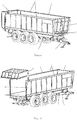
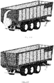
- the Figure 1 illustrates a phase of work in which a transport trailer according to the invention, or more generally a means of transport according to the invention, is ready to be loaded. It represents a loading box 1 of this transport trailer, according to the invention, which has also been shown the support frame 2 and the drawbar 3, two elements irrelevant to the invention, but indicating the normal direction of progress of the trailer.
- the loading box 1 is composed of side walls 4, a rear door 5 designed in this example as a pivoting closure box at the rear of the side walls 4, a movable wall 6 located in the working position illustrated, between the front ends of the side walls 4, and a bottom structure 7.
- the Figure 2 represents the same loading box 1, in a work phase ready for unloading, where the rear door 5 has pivoted upwards under the action of door jacks 8, thus releasing an unloading bay at the rear of the trailer.
- the bay clearance unloading on this Figure 2 suggests the bottom mat 9 disposed on the entire surface of the bottom structure 7.
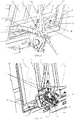
- the Figure 3 represents a partial view of the lower side of the transport case 1, in the part located under the rear unloading bay.
- the base mat 9 wraps around the winding drum 11 under the action of a gear 12 driven by a hydraulic motor 13.
- the exemplary embodiment considered provides a second gear 12 and a second motor hydraulic 13 on the opposite side of the winding drum 11.
- the winding device of the base mat 9 is advantageously completed by a return drum 14 under which is disposed a scraper 15 mounted on a support 16.
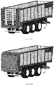
- the Figure 4 represents the aforementioned loading box 1 seen from above, during the unloading process.
- the base mat 9 retreats towards the rear, attracting with it the movable wall 6, at the same time as the transported material, not shown.
- This movement has the effect of discharging the material at the rear of the trailer, without the dome of transported material is poured forward of the loading box 1 since the front wall 6 also moves backwards.
- the user will gain in terms of unloading time, since he must not wait for the material dropped to be discharged into the part that is gradually disengaged at the front of the body during the rotation of the moving floor.
- the mobile wall 6 undergoes only a minimal stress, equivalent to the pressure of the material which leans directly on it, and not on the weight of all the material contained in the crate 1.
- the Figure 4 also shows explicitly the structure of the bottom of the body 7, composed of a set of sheets provided with folds forming valleys 36 (better visible on the Figure 7 ), themselves provided with orifices for evacuating any residues.
- This structure having openings allows extremely easy maintenance of the interior of the loading box 1 when the base mat 9 has been fully wound on the rear drum 11.
- the residual materials non-sticky fall naturally under the action of the scraper 20 located at the base of the movable wall 6 (see Figures 6 and 7 ), during the displacement of the latter, and the auxiliary liquid, for example the water of a high-pressure cleaner, will follow the same path.
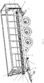
- the Figure 5 illustrates the end of the unloading process of the loading box 1.
- the process of winding the conveyor belt 9 is completed, the movable wall 6 has joined the rear end, finishing to dump all the transported material.
- the Figure 6 represents a close-up view of the mobile wall 6 in the default position, that is to say on the side of the loading box 1 opposite the unloading bay. In the exemplary illustrated embodiment, this position is located at the front of the load case 1.
- the movable wall 6 is composed of a partition 17 made here using a structure composed for example of a reinforced frame of one or more crosspieces and covered with a plate 10 made for example of transparent thermoplastic polymer ( why spaces between the frame and the sleepers appear empty on the Figure 6 but full on the Figure 5 ) to provide the driver of the towing vehicle with maximum visibility of the material being transported.
- a partition 17 made here using a structure composed for example of a reinforced frame of one or more crosspieces and covered with a plate 10 made for example of transparent thermoplastic polymer ( why spaces between the frame and the sleepers appear empty on the Figure 6 but full on the Figure 5 ) to provide the driver of the towing vehicle with maximum visibility of the material being transported.
- the construction of this partition 17 is not a characterizing element of the patent, as long as it is sufficiently resistant.
- the movable wall 6 further comprises a fastening device 18 which solidifies it with the base mat 9.
- this fastening device 18 is not characterizing, it being understood that it must be in a state of repair. durably ensure uniform traction of the movable wall 6 by the base mat 9.
- the movable wall 6 further comprises a guide and holding bridge 19 which, as indicated by its name, is intended to keep the movable wall 6 continuously perpendicular to the side walls 4, which will have the side effect of guaranteeing the regular winding and in line of the bottom mat 9, and to maintain the movable wall 6 in the angle of its construction, that is to say to prevent it from tilting or swinging back and forth and vice versa under the effect of the pressure of the transported load and / or its own displacement and / or any other foreseeable force (wind, wind, etc.).
- a guide and holding bridge 19 which, as indicated by its name, is intended to keep the movable wall 6 continuously perpendicular to the side walls 4, which will have the side effect of guaranteeing the regular winding and in line of the bottom mat 9, and to maintain the movable wall 6 in the angle of its construction, that is to say to prevent it from tilting or swinging back and forth and vice versa under the effect of the pressure of the transported load and / or its own displacement and / or any other foreseeable force
- FIG. 7 there is the body bottom structure 7 and the wiper seal 20 which matches the shape to evacuate any residues through the orifices in the valleys 36 of the bottom 7.
- a set of wheels The upper rollers 21, four in the illustrated embodiment without such a number having a characterizing value, are furthermore arranged at the base of the guiding and holding bridge 19. These upper rollers 21 are each arranged in the same direction. longitudinal axis of one of the guide rails 22 constituting a guide channel 24 and roll on these rails 22 when the bottom mat 9 and the movable wall 6 move towards the unloading bay.
- This device combining guide rails 22 and upper rollers 21 has the effect of reducing the tensile force exerted on the movable wall 6 during its displacement as well as the pressure force exerted on the background carpet 9 when it slides on the bottom structure 7 during its winding around the drum drum 11.
- the Figure 8 also shows a set of lower rollers 23, two in number in the illustrated embodiment without such a number having characterizing value, structurally fixed to the bridge 19 but whose height position corresponds to the height of the internal rails 22, designed such that they realize the guide channel 24 which holds and guides the lower wheels 23.
- the Figure 7 still shows a protective cover 25 disposed in the center of the base of the bridge 19.
- This protective cover 25 is intended to protect the guide channel 24 when the machine is in the loading and / or transport phase: thus avoiding the material is deposited at the place where the upper central rollers 21 and the lower rollers 23 will have to pass at the beginning of the unloading phase.
- the protective cover 25 is also used for fixing the lower rollers 23, fastening completed by an adjustment nut 26 (also visible on the figure 10 ) for adjusting the vertical position of the lower rollers 23 relative to the height of the guide channel 24, as well as the fastening of the chain tensioner 34.
- the Figure 9 shows a general cutaway view of the bottom of the body according to the invention.
- a chain 27 extending around a front drive pinion 28 and a rear idler gear 29 .
- the chain 27 is provided with a connecting piece 30 solidarisant the chain 27 with the bridge 19.
- a gear 31 actuated by any power system, here a hydraulic motor 32, can move the chain 27 in both directions.
- the power system 32 of the chain 27 is synchronized with the power system 13 of the winding drum 11 of the belt 9 , so that the movement speeds of the belt 9 and the chain 27 are identical in the unloading phase.
- the chain 27 thus assists the winding drum 11 through the connecting piece 30, each pulling in the same direction by one end of the belt 9.
- the power system 13 rotates freely and only the power system 32 drives the whole, the chain 27 serving as a return device via the connecting piece 30.
- the Figure 10 shows a cutaway view of the anterior portion of the guide channel 24 and the base of the bridge 19.
- the upper guide rollers 21, a bearing 33 of the lower roller 23, the chain 27, the drive gear 28 , the gear 31, the hydraulic motor 32, the connecting piece 30, the adjusting nut 26 and the chain tensioner 34 are two of the upper guide rollers 21, a bearing 33 of the lower roller 23, the chain 27, the drive gear 28 , the gear 31, the hydraulic motor 32, the connecting piece 30, the adjusting nut 26 and the chain tensioner 34.
- the connecting piece 30 also incorporates the shaft of the lower castors 23, so that the threaded shaft leading to the nut 26 allows both to make the connection to the bridge 19 and adjust the height of the lower rollers 23, ensuring at the same time a maintenance of the chain 27.
- One end of the chain 27 is fixed to the tensioner 34, integrated with the bridge 19, the other end being fixed to the connecting piece 30, itself also fixed to the bridge 19.
- the tensioner 24 compensates for the lengthening of the chain 27 which occurs when it is set in motion, under the effect of the traction exerted by the drive pinion 28.
- the tensile stress affects in effect the almost total length of the chain 27, from the links located around the drive pinion 28 to the link fixed to the connecting piece 30.
- the chain 27 can then lengthen several centimeters which will be compensated by the extension of the springs 35 of the tensioner 34.
Landscapes
- Engineering & Computer Science (AREA)
- Transportation (AREA)
- Mechanical Engineering (AREA)
- Loading Or Unloading Of Vehicles (AREA)
- Machines For Laying And Maintaining Railways (AREA)
Priority Applications (1)
| Application Number | Priority Date | Filing Date | Title |
|---|---|---|---|
| PL15197074T PL3028895T3 (pl) | 2014-12-05 | 2015-11-30 | Urządzenie wspomagające rozładunek przyczepy transportowej z nawijanym przenośnikiem taśmowym |
Applications Claiming Priority (1)
| Application Number | Priority Date | Filing Date | Title |
|---|---|---|---|
| BE20145104A BE1022616A9 (fr) | 2014-12-05 | 2014-12-05 | Dispositif d'assistance au déchargement d'une remorque de transport a tapis enrouleur |
Publications (2)
| Publication Number | Publication Date |
|---|---|
| EP3028895A1 EP3028895A1 (fr) | 2016-06-08 |
| EP3028895B1 true EP3028895B1 (fr) | 2017-09-27 |
Family
ID=52736783
Family Applications (1)
| Application Number | Title | Priority Date | Filing Date |
|---|---|---|---|
| EP15197074.6A Active EP3028895B1 (fr) | 2014-12-05 | 2015-11-30 | Dispositif d'assistance au déchargement d'une remorque de transport a tapis enrouleur |
Country Status (4)
| Country | Link |
|---|---|
| EP (1) | EP3028895B1 (pl) |
| BE (1) | BE1022616A9 (pl) |
| ES (1) | ES2648807T3 (pl) |
| PL (1) | PL3028895T3 (pl) |
Cited By (1)
| Publication number | Priority date | Publication date | Assignee | Title |
|---|---|---|---|---|
| DE102017115419A1 (de) * | 2017-07-10 | 2019-01-10 | Langendorf Gmbh | Fahrzeugaufbau mit Gleitbandeinheit |
Families Citing this family (3)
| Publication number | Priority date | Publication date | Assignee | Title |
|---|---|---|---|---|
| CN107082039A (zh) * | 2017-05-18 | 2017-08-22 | 威海顺丰专用车制造有限公司 | 一种车载散货自卸系统 |
| CN110466612B (zh) * | 2019-07-23 | 2025-05-16 | 山东畅达专用车有限公司 | 一种新型自卸挂车车架 |
| CN113525208B (zh) * | 2021-08-16 | 2022-11-08 | 山东亚中车辆股份有限公司 | 一种特种车辆 |
Family Cites Families (6)
| Publication number | Priority date | Publication date | Assignee | Title |
|---|---|---|---|---|
| US3498482A (en) * | 1968-07-30 | 1970-03-03 | Western Sawdust Products Inc | Truck-body unloading apparatus |
| GB2351063B (en) * | 1999-06-15 | 2003-08-20 | Multidrive Ltd | Load carrying body |
| DE20117346U1 (de) | 2001-08-25 | 2002-03-28 | Annaburger Nutzfahrzeug GmbH, 06925 Annaburg | Ladewagen mit Entladungseinrichtung |
| JP5328228B2 (ja) * | 2008-05-26 | 2013-10-30 | 株式会社立和運輸倉庫 | 車両用荷役装置 |
| CA2709797C (en) * | 2009-12-10 | 2013-02-12 | Harvey Stewart | Light-weight live-floor module for trailers |
| BE1019861A3 (fr) | 2011-03-10 | 2013-01-08 | Joskin Ets | Remorque de transport a dechargement par tapis enrouleur. |
-
2014
- 2014-12-05 BE BE20145104A patent/BE1022616A9/fr not_active IP Right Cessation
-
2015
- 2015-11-30 PL PL15197074T patent/PL3028895T3/pl unknown
- 2015-11-30 EP EP15197074.6A patent/EP3028895B1/fr active Active
- 2015-11-30 ES ES15197074.6T patent/ES2648807T3/es active Active
Non-Patent Citations (1)
| Title |
|---|
| None * |
Cited By (1)
| Publication number | Priority date | Publication date | Assignee | Title |
|---|---|---|---|---|
| DE102017115419A1 (de) * | 2017-07-10 | 2019-01-10 | Langendorf Gmbh | Fahrzeugaufbau mit Gleitbandeinheit |
Also Published As
| Publication number | Publication date |
|---|---|
| BE1022616A9 (fr) | 2016-10-07 |
| ES2648807T3 (es) | 2018-01-08 |
| BE1022616B1 (fr) | 2016-06-16 |
| EP3028895A1 (fr) | 2016-06-08 |
| BE1022616A1 (fr) | 2016-06-16 |
| PL3028895T3 (pl) | 2018-04-30 |
Similar Documents
| Publication | Publication Date | Title |
|---|---|---|
| EP3028895B1 (fr) | Dispositif d'assistance au déchargement d'une remorque de transport a tapis enrouleur | |
| CH398456A (fr) | Récipient pour l'emmagasinage ou le transport de matériaux ou de marchandises | |
| EP1742858B1 (fr) | Installation et procede pour le transfert de charge entre une plate-forme de transfert et un vehicule de transport | |
| EP2497684A1 (fr) | Remorque de transport a dechargement par tapis enrouleur | |
| EP2878551B1 (fr) | Dispositif de bâchage/débâchage latéral d'un caisson de chargement de type benne, vehicle et caisson de chargement pourvu de ce dispositif | |
| EP2070850B1 (fr) | Installation de chargement de produits divisés dans des bennes | |
| EP3749548B1 (fr) | Vehicule de transport de materiaux | |
| FR2971492A1 (fr) | Benne de compactage pour la collecte d'une charge du type dechets menagers et procede de transfert de la charge d'une telle benne vers un conteneur | |
| EP3687856B1 (fr) | Plateau de chargement pour voiture à traverse coulissante de type panier | |
| EP0391804A1 (fr) | Dispositif de chargement et de déchargement de balles cylindriques de paille ou de fourragé | |
| EP2493714B1 (fr) | Dispositif de deroulement et d'enroulement automatique d'une bache | |
| EP1020312A1 (fr) | Dispositif de couverture de conteneur | |
| FR2649856A1 (fr) | Dispositif pour l'arrachage de produits agricoles a racine | |
| FR3099145A1 (fr) | Caisson de chargement a fond mouvant et a cloison de dechargement mobile en translation | |
| EP0165113A1 (fr) | Dispositif de bâchage et de débâchage | |
| FR3023253A1 (fr) | Remorque avec benne a hauteur variable et plateau convoyeur autonome | |
| FR3032662A1 (fr) | Benne comprenant un module de distribution amovible et module de distribution associe | |
| FR2978434A1 (fr) | Ensemble a benne et vehicule motorise pour le transport propre de dechets | |
| BE1019730A3 (fr) | Dispositif de conditionnement pour produits d'agriculture, en particulier poireaux. | |
| FR2908092A1 (fr) | Dispositif de chargement et/ou dechargement d'un vehicule de transport, module de plancher d'un vehicule de transport et vehicule de transport | |
| FR2970918A1 (fr) | Garniture pour benne dechargeable par l'arriere, benne equipee d'une telle garniture et son procede de chargement/dechargement | |
| EP2536590A1 (fr) | Benne de camion a paroi de fond recouverte d'une bande sans fin d'amortissement, et camion ainsi equipe | |
| EP1588894A1 (fr) | Dispositif tracté supportant un accessoire amovible tel qu'une benne | |
| EP0027409A1 (fr) | Caisses à fond mobile | |
| FR2941219A1 (fr) | Vehicule equipe d'une systeme de manutention pour contenants amovibles |
Legal Events
| Date | Code | Title | Description |
|---|---|---|---|
| PUAI | Public reference made under article 153(3) epc to a published international application that has entered the european phase |
Free format text: ORIGINAL CODE: 0009012 |
|
| AK | Designated contracting states |
Kind code of ref document: A1 Designated state(s): AL AT BE BG CH CY CZ DE DK EE ES FI FR GB GR HR HU IE IS IT LI LT LU LV MC MK MT NL NO PL PT RO RS SE SI SK SM TR |
|
| AX | Request for extension of the european patent |
Extension state: BA ME |
|
| 17P | Request for examination filed |
Effective date: 20161123 |
|
| RBV | Designated contracting states (corrected) |
Designated state(s): AL AT BE BG CH CY CZ DE DK EE ES FI FR GB GR HR HU IE IS IT LI LT LU LV MC MK MT NL NO PL PT RO RS SE SI SK SM TR |
|
| GRAP | Despatch of communication of intention to grant a patent |
Free format text: ORIGINAL CODE: EPIDOSNIGR1 |
|
| INTG | Intention to grant announced |
Effective date: 20170322 |
|
| GRAS | Grant fee paid |
Free format text: ORIGINAL CODE: EPIDOSNIGR3 |
|
| GRAJ | Information related to disapproval of communication of intention to grant by the applicant or resumption of examination proceedings by the epo deleted |
Free format text: ORIGINAL CODE: EPIDOSDIGR1 |
|
| GRAL | Information related to payment of fee for publishing/printing deleted |
Free format text: ORIGINAL CODE: EPIDOSDIGR3 |
|
| GRAP | Despatch of communication of intention to grant a patent |
Free format text: ORIGINAL CODE: EPIDOSNIGR1 |
|
| INTC | Intention to grant announced (deleted) | ||
| GRAA | (expected) grant |
Free format text: ORIGINAL CODE: 0009210 |
|
| INTG | Intention to grant announced |
Effective date: 20170808 |
|
| AK | Designated contracting states |
Kind code of ref document: B1 Designated state(s): AL AT BE BG CH CY CZ DE DK EE ES FI FR GB GR HR HU IE IS IT LI LT LU LV MC MK MT NL NO PL PT RO RS SE SI SK SM TR |
|
| REG | Reference to a national code |
Ref country code: GB Ref legal event code: FG4D Free format text: NOT ENGLISH |
|
| REG | Reference to a national code |
Ref country code: CH Ref legal event code: EP |
|
| REG | Reference to a national code |
Ref country code: AT Ref legal event code: REF Ref document number: 931632 Country of ref document: AT Kind code of ref document: T Effective date: 20171015 |
|
| REG | Reference to a national code |
Ref country code: IE Ref legal event code: FG4D Free format text: LANGUAGE OF EP DOCUMENT: FRENCH |
|
| REG | Reference to a national code |
Ref country code: FR Ref legal event code: PLFP Year of fee payment: 3 |
|
| REG | Reference to a national code |
Ref country code: DE Ref legal event code: R096 Ref document number: 602015004994 Country of ref document: DE |
|
| REG | Reference to a national code |
Ref country code: ES Ref legal event code: FG2A Ref document number: 2648807 Country of ref document: ES Kind code of ref document: T3 Effective date: 20180108 |
|
| REG | Reference to a national code |
Ref country code: NL Ref legal event code: FP |
|
| PG25 | Lapsed in a contracting state [announced via postgrant information from national office to epo] |
Ref country code: HR Free format text: LAPSE BECAUSE OF FAILURE TO SUBMIT A TRANSLATION OF THE DESCRIPTION OR TO PAY THE FEE WITHIN THE PRESCRIBED TIME-LIMIT Effective date: 20170927 Ref country code: FI Free format text: LAPSE BECAUSE OF FAILURE TO SUBMIT A TRANSLATION OF THE DESCRIPTION OR TO PAY THE FEE WITHIN THE PRESCRIBED TIME-LIMIT Effective date: 20170927 Ref country code: NO Free format text: LAPSE BECAUSE OF FAILURE TO SUBMIT A TRANSLATION OF THE DESCRIPTION OR TO PAY THE FEE WITHIN THE PRESCRIBED TIME-LIMIT Effective date: 20171227 Ref country code: LT Free format text: LAPSE BECAUSE OF FAILURE TO SUBMIT A TRANSLATION OF THE DESCRIPTION OR TO PAY THE FEE WITHIN THE PRESCRIBED TIME-LIMIT Effective date: 20170927 Ref country code: SE Free format text: LAPSE BECAUSE OF FAILURE TO SUBMIT A TRANSLATION OF THE DESCRIPTION OR TO PAY THE FEE WITHIN THE PRESCRIBED TIME-LIMIT Effective date: 20170927 |
|
| REG | Reference to a national code |
Ref country code: LT Ref legal event code: MG4D |
|
| REG | Reference to a national code |
Ref country code: AT Ref legal event code: MK05 Ref document number: 931632 Country of ref document: AT Kind code of ref document: T Effective date: 20170927 |
|
| PG25 | Lapsed in a contracting state [announced via postgrant information from national office to epo] |
Ref country code: RS Free format text: LAPSE BECAUSE OF FAILURE TO SUBMIT A TRANSLATION OF THE DESCRIPTION OR TO PAY THE FEE WITHIN THE PRESCRIBED TIME-LIMIT Effective date: 20170927 Ref country code: GR Free format text: LAPSE BECAUSE OF FAILURE TO SUBMIT A TRANSLATION OF THE DESCRIPTION OR TO PAY THE FEE WITHIN THE PRESCRIBED TIME-LIMIT Effective date: 20171228 Ref country code: BG Free format text: LAPSE BECAUSE OF FAILURE TO SUBMIT A TRANSLATION OF THE DESCRIPTION OR TO PAY THE FEE WITHIN THE PRESCRIBED TIME-LIMIT Effective date: 20171227 Ref country code: LV Free format text: LAPSE BECAUSE OF FAILURE TO SUBMIT A TRANSLATION OF THE DESCRIPTION OR TO PAY THE FEE WITHIN THE PRESCRIBED TIME-LIMIT Effective date: 20170927 |
|
| PG25 | Lapsed in a contracting state [announced via postgrant information from national office to epo] |
Ref country code: CZ Free format text: LAPSE BECAUSE OF FAILURE TO SUBMIT A TRANSLATION OF THE DESCRIPTION OR TO PAY THE FEE WITHIN THE PRESCRIBED TIME-LIMIT Effective date: 20170927 Ref country code: RO Free format text: LAPSE BECAUSE OF FAILURE TO SUBMIT A TRANSLATION OF THE DESCRIPTION OR TO PAY THE FEE WITHIN THE PRESCRIBED TIME-LIMIT Effective date: 20170927 |
|
| PG25 | Lapsed in a contracting state [announced via postgrant information from national office to epo] |
Ref country code: IS Free format text: LAPSE BECAUSE OF FAILURE TO SUBMIT A TRANSLATION OF THE DESCRIPTION OR TO PAY THE FEE WITHIN THE PRESCRIBED TIME-LIMIT Effective date: 20180127 Ref country code: SM Free format text: LAPSE BECAUSE OF FAILURE TO SUBMIT A TRANSLATION OF THE DESCRIPTION OR TO PAY THE FEE WITHIN THE PRESCRIBED TIME-LIMIT Effective date: 20170927 Ref country code: AT Free format text: LAPSE BECAUSE OF FAILURE TO SUBMIT A TRANSLATION OF THE DESCRIPTION OR TO PAY THE FEE WITHIN THE PRESCRIBED TIME-LIMIT Effective date: 20170927 Ref country code: SK Free format text: LAPSE BECAUSE OF FAILURE TO SUBMIT A TRANSLATION OF THE DESCRIPTION OR TO PAY THE FEE WITHIN THE PRESCRIBED TIME-LIMIT Effective date: 20170927 Ref country code: EE Free format text: LAPSE BECAUSE OF FAILURE TO SUBMIT A TRANSLATION OF THE DESCRIPTION OR TO PAY THE FEE WITHIN THE PRESCRIBED TIME-LIMIT Effective date: 20170927 |
|
| REG | Reference to a national code |
Ref country code: DE Ref legal event code: R097 Ref document number: 602015004994 Country of ref document: DE |
|
| PG25 | Lapsed in a contracting state [announced via postgrant information from national office to epo] |
Ref country code: MC Free format text: LAPSE BECAUSE OF FAILURE TO SUBMIT A TRANSLATION OF THE DESCRIPTION OR TO PAY THE FEE WITHIN THE PRESCRIBED TIME-LIMIT Effective date: 20170927 |
|
| PG25 | Lapsed in a contracting state [announced via postgrant information from national office to epo] |
Ref country code: DK Free format text: LAPSE BECAUSE OF FAILURE TO SUBMIT A TRANSLATION OF THE DESCRIPTION OR TO PAY THE FEE WITHIN THE PRESCRIBED TIME-LIMIT Effective date: 20170927 |
|
| PLBE | No opposition filed within time limit |
Free format text: ORIGINAL CODE: 0009261 |
|
| STAA | Information on the status of an ep patent application or granted ep patent |
Free format text: STATUS: NO OPPOSITION FILED WITHIN TIME LIMIT |
|
| PG25 | Lapsed in a contracting state [announced via postgrant information from national office to epo] |
Ref country code: LU Free format text: LAPSE BECAUSE OF NON-PAYMENT OF DUE FEES Effective date: 20171130 |
|
| 26N | No opposition filed |
Effective date: 20180628 |
|
| PG25 | Lapsed in a contracting state [announced via postgrant information from national office to epo] |
Ref country code: MT Free format text: LAPSE BECAUSE OF FAILURE TO SUBMIT A TRANSLATION OF THE DESCRIPTION OR TO PAY THE FEE WITHIN THE PRESCRIBED TIME-LIMIT Effective date: 20170927 |
|
| REG | Reference to a national code |
Ref country code: FR Ref legal event code: PLFP Year of fee payment: 4 |
|
| PG25 | Lapsed in a contracting state [announced via postgrant information from national office to epo] |
Ref country code: SI Free format text: LAPSE BECAUSE OF FAILURE TO SUBMIT A TRANSLATION OF THE DESCRIPTION OR TO PAY THE FEE WITHIN THE PRESCRIBED TIME-LIMIT Effective date: 20170927 |
|
| PG25 | Lapsed in a contracting state [announced via postgrant information from national office to epo] |
Ref country code: HU Free format text: LAPSE BECAUSE OF FAILURE TO SUBMIT A TRANSLATION OF THE DESCRIPTION OR TO PAY THE FEE WITHIN THE PRESCRIBED TIME-LIMIT; INVALID AB INITIO Effective date: 20151130 |
|
| REG | Reference to a national code |
Ref country code: CH Ref legal event code: PL |
|
| PG25 | Lapsed in a contracting state [announced via postgrant information from national office to epo] |
Ref country code: LI Free format text: LAPSE BECAUSE OF NON-PAYMENT OF DUE FEES Effective date: 20181130 Ref country code: CH Free format text: LAPSE BECAUSE OF NON-PAYMENT OF DUE FEES Effective date: 20181130 |
|
| PG25 | Lapsed in a contracting state [announced via postgrant information from national office to epo] |
Ref country code: CY Free format text: LAPSE BECAUSE OF FAILURE TO SUBMIT A TRANSLATION OF THE DESCRIPTION OR TO PAY THE FEE WITHIN THE PRESCRIBED TIME-LIMIT Effective date: 20170927 |
|
| PG25 | Lapsed in a contracting state [announced via postgrant information from national office to epo] |
Ref country code: MK Free format text: LAPSE BECAUSE OF FAILURE TO SUBMIT A TRANSLATION OF THE DESCRIPTION OR TO PAY THE FEE WITHIN THE PRESCRIBED TIME-LIMIT Effective date: 20170927 |
|
| PG25 | Lapsed in a contracting state [announced via postgrant information from national office to epo] |
Ref country code: TR Free format text: LAPSE BECAUSE OF FAILURE TO SUBMIT A TRANSLATION OF THE DESCRIPTION OR TO PAY THE FEE WITHIN THE PRESCRIBED TIME-LIMIT Effective date: 20170927 |
|
| PG25 | Lapsed in a contracting state [announced via postgrant information from national office to epo] |
Ref country code: PT Free format text: LAPSE BECAUSE OF FAILURE TO SUBMIT A TRANSLATION OF THE DESCRIPTION OR TO PAY THE FEE WITHIN THE PRESCRIBED TIME-LIMIT Effective date: 20170927 |
|
| PG25 | Lapsed in a contracting state [announced via postgrant information from national office to epo] |
Ref country code: AL Free format text: LAPSE BECAUSE OF FAILURE TO SUBMIT A TRANSLATION OF THE DESCRIPTION OR TO PAY THE FEE WITHIN THE PRESCRIBED TIME-LIMIT Effective date: 20170927 |
|
| PGFP | Annual fee paid to national office [announced via postgrant information from national office to epo] |
Ref country code: PL Payment date: 20241023 Year of fee payment: 10 |
|
| PGFP | Annual fee paid to national office [announced via postgrant information from national office to epo] |
Ref country code: NL Payment date: 20251022 Year of fee payment: 11 |
|
| PGFP | Annual fee paid to national office [announced via postgrant information from national office to epo] |
Ref country code: DE Payment date: 20251022 Year of fee payment: 11 |
|
| PGFP | Annual fee paid to national office [announced via postgrant information from national office to epo] |
Ref country code: GB Payment date: 20251022 Year of fee payment: 11 |
|
| PGFP | Annual fee paid to national office [announced via postgrant information from national office to epo] |
Ref country code: IT Payment date: 20251022 Year of fee payment: 11 |
|
| PGFP | Annual fee paid to national office [announced via postgrant information from national office to epo] |
Ref country code: FR Payment date: 20251022 Year of fee payment: 11 |
|
| PGFP | Annual fee paid to national office [announced via postgrant information from national office to epo] |
Ref country code: BE Payment date: 20251022 Year of fee payment: 11 |
|
| PGFP | Annual fee paid to national office [announced via postgrant information from national office to epo] |
Ref country code: IE Payment date: 20251024 Year of fee payment: 11 |
|
| PGFP | Annual fee paid to national office [announced via postgrant information from national office to epo] |
Ref country code: ES Payment date: 20251201 Year of fee payment: 11 |