EP3028655B1 - Locking element for a polyaxial bone anchor, bone plate assembly and tool - Google Patents
Locking element for a polyaxial bone anchor, bone plate assembly and tool Download PDFInfo
- Publication number
- EP3028655B1 EP3028655B1 EP15203135.7A EP15203135A EP3028655B1 EP 3028655 B1 EP3028655 B1 EP 3028655B1 EP 15203135 A EP15203135 A EP 15203135A EP 3028655 B1 EP3028655 B1 EP 3028655B1
- Authority
- EP
- European Patent Office
- Prior art keywords
- locking element
- head
- bone
- recess
- top side
- Prior art date
- Legal status (The legal status is an assumption and is not a legal conclusion. Google has not performed a legal analysis and makes no representation as to the accuracy of the status listed.)
- Active
Links
Images


Classifications
-
- A—HUMAN NECESSITIES
- A61—MEDICAL OR VETERINARY SCIENCE; HYGIENE
- A61B—DIAGNOSIS; SURGERY; IDENTIFICATION
- A61B17/00—Surgical instruments, devices or methods
- A61B17/56—Surgical instruments or methods for treatment of bones or joints; Devices specially adapted therefor
- A61B17/58—Surgical instruments or methods for treatment of bones or joints; Devices specially adapted therefor for osteosynthesis, e.g. bone plates, screws or setting implements
- A61B17/68—Internal fixation devices, including fasteners and spinal fixators, even if a part thereof projects from the skin
- A61B17/80—Cortical plates, i.e. bone plates; Instruments for holding or positioning cortical plates, or for compressing bones attached to cortical plates
- A61B17/8052—Cortical plates, i.e. bone plates; Instruments for holding or positioning cortical plates, or for compressing bones attached to cortical plates immobilised relative to screws by interlocking form of the heads and plate holes, e.g. conical or threaded
- A61B17/8057—Cortical plates, i.e. bone plates; Instruments for holding or positioning cortical plates, or for compressing bones attached to cortical plates immobilised relative to screws by interlocking form of the heads and plate holes, e.g. conical or threaded the interlocking form comprising a thread
-
- A—HUMAN NECESSITIES
- A61—MEDICAL OR VETERINARY SCIENCE; HYGIENE
- A61B—DIAGNOSIS; SURGERY; IDENTIFICATION
- A61B17/00—Surgical instruments, devices or methods
- A61B17/56—Surgical instruments or methods for treatment of bones or joints; Devices specially adapted therefor
- A61B17/58—Surgical instruments or methods for treatment of bones or joints; Devices specially adapted therefor for osteosynthesis, e.g. bone plates, screws or setting implements
- A61B17/68—Internal fixation devices, including fasteners and spinal fixators, even if a part thereof projects from the skin
- A61B17/80—Cortical plates, i.e. bone plates; Instruments for holding or positioning cortical plates, or for compressing bones attached to cortical plates
- A61B17/8033—Cortical plates, i.e. bone plates; Instruments for holding or positioning cortical plates, or for compressing bones attached to cortical plates having indirect contact with screw heads, or having contact with screw heads maintained with the aid of additional components, e.g. nuts, wedges or head covers
- A61B17/8042—Cortical plates, i.e. bone plates; Instruments for holding or positioning cortical plates, or for compressing bones attached to cortical plates having indirect contact with screw heads, or having contact with screw heads maintained with the aid of additional components, e.g. nuts, wedges or head covers the additional component being a cover over the screw head
-
- A—HUMAN NECESSITIES
- A61—MEDICAL OR VETERINARY SCIENCE; HYGIENE
- A61B—DIAGNOSIS; SURGERY; IDENTIFICATION
- A61B17/00—Surgical instruments, devices or methods
- A61B17/56—Surgical instruments or methods for treatment of bones or joints; Devices specially adapted therefor
- A61B17/58—Surgical instruments or methods for treatment of bones or joints; Devices specially adapted therefor for osteosynthesis, e.g. bone plates, screws or setting implements
- A61B17/68—Internal fixation devices, including fasteners and spinal fixators, even if a part thereof projects from the skin
- A61B17/80—Cortical plates, i.e. bone plates; Instruments for holding or positioning cortical plates, or for compressing bones attached to cortical plates
- A61B17/808—Instruments for holding or positioning bone plates, or for adjusting screw-to-plate locking mechanisms
-
- A—HUMAN NECESSITIES
- A61—MEDICAL OR VETERINARY SCIENCE; HYGIENE
- A61B—DIAGNOSIS; SURGERY; IDENTIFICATION
- A61B17/00—Surgical instruments, devices or methods
- A61B17/56—Surgical instruments or methods for treatment of bones or joints; Devices specially adapted therefor
- A61B17/58—Surgical instruments or methods for treatment of bones or joints; Devices specially adapted therefor for osteosynthesis, e.g. bone plates, screws or setting implements
- A61B17/68—Internal fixation devices, including fasteners and spinal fixators, even if a part thereof projects from the skin
- A61B17/84—Fasteners therefor or fasteners being internal fixation devices
- A61B17/86—Pins or screws or threaded wires; nuts therefor
- A61B17/8605—Heads, i.e. proximal ends projecting from bone
- A61B17/861—Heads, i.e. proximal ends projecting from bone specially shaped for gripping driver
- A61B17/8615—Heads, i.e. proximal ends projecting from bone specially shaped for gripping driver at the central region of the screw head
-
- A—HUMAN NECESSITIES
- A61—MEDICAL OR VETERINARY SCIENCE; HYGIENE
- A61B—DIAGNOSIS; SURGERY; IDENTIFICATION
- A61B17/00—Surgical instruments, devices or methods
- A61B17/56—Surgical instruments or methods for treatment of bones or joints; Devices specially adapted therefor
- A61B17/58—Surgical instruments or methods for treatment of bones or joints; Devices specially adapted therefor for osteosynthesis, e.g. bone plates, screws or setting implements
- A61B17/88—Osteosynthesis instruments; Methods or means for implanting or extracting internal or external fixation devices
- A61B17/8875—Screwdrivers, spanners or wrenches
- A61B17/8877—Screwdrivers, spanners or wrenches characterised by the cross-section of the driver bit
-
- A—HUMAN NECESSITIES
- A61—MEDICAL OR VETERINARY SCIENCE; HYGIENE
- A61B—DIAGNOSIS; SURGERY; IDENTIFICATION
- A61B17/00—Surgical instruments, devices or methods
- A61B17/56—Surgical instruments or methods for treatment of bones or joints; Devices specially adapted therefor
- A61B17/58—Surgical instruments or methods for treatment of bones or joints; Devices specially adapted therefor for osteosynthesis, e.g. bone plates, screws or setting implements
- A61B17/68—Internal fixation devices, including fasteners and spinal fixators, even if a part thereof projects from the skin
- A61B17/80—Cortical plates, i.e. bone plates; Instruments for holding or positioning cortical plates, or for compressing bones attached to cortical plates
- A61B17/8033—Cortical plates, i.e. bone plates; Instruments for holding or positioning cortical plates, or for compressing bones attached to cortical plates having indirect contact with screw heads, or having contact with screw heads maintained with the aid of additional components, e.g. nuts, wedges or head covers
-
- F—MECHANICAL ENGINEERING; LIGHTING; HEATING; WEAPONS; BLASTING
- F16—ENGINEERING ELEMENTS AND UNITS; GENERAL MEASURES FOR PRODUCING AND MAINTAINING EFFECTIVE FUNCTIONING OF MACHINES OR INSTALLATIONS; THERMAL INSULATION IN GENERAL
- F16B—DEVICES FOR FASTENING OR SECURING CONSTRUCTIONAL ELEMENTS OR MACHINE PARTS TOGETHER, e.g. NAILS, BOLTS, CIRCLIPS, CLAMPS, CLIPS OR WEDGES; JOINTS OR JOINTING
- F16B23/00—Specially shaped nuts or heads of bolts or screws for rotations by a tool
- F16B23/0007—Specially shaped nuts or heads of bolts or screws for rotations by a tool characterised by the shape of the recess or the protrusion engaging the tool
- F16B23/003—Specially shaped nuts or heads of bolts or screws for rotations by a tool characterised by the shape of the recess or the protrusion engaging the tool star-shaped or multi-lobular, e.g. Torx-type, twelve-point star
-
- F—MECHANICAL ENGINEERING; LIGHTING; HEATING; WEAPONS; BLASTING
- F16—ENGINEERING ELEMENTS AND UNITS; GENERAL MEASURES FOR PRODUCING AND MAINTAINING EFFECTIVE FUNCTIONING OF MACHINES OR INSTALLATIONS; THERMAL INSULATION IN GENERAL
- F16B—DEVICES FOR FASTENING OR SECURING CONSTRUCTIONAL ELEMENTS OR MACHINE PARTS TOGETHER, e.g. NAILS, BOLTS, CIRCLIPS, CLAMPS, CLIPS OR WEDGES; JOINTS OR JOINTING
- F16B23/00—Specially shaped nuts or heads of bolts or screws for rotations by a tool
- F16B23/0061—Specially shaped nuts or heads of bolts or screws for rotations by a tool with grooves, notches or splines on the external peripheral surface designed for tools engaging in radial direction
Definitions
- the invention relates to a locking element for a polyaxial bone anchor and to a bone plate assembly for the immobilization of bones or bone fragments or vertebrae and a tool used therefor.
- the invention relates to a bone plate assembly with a polyaxial coupling between the bone anchors of the bone plate assembly and a plate with an increased range of angular motion and low profile.
- US 6,022,350 describes a bone fixing device comprising an elongate single-piece plate-shaped element receiving at least one bone-fastening screw which passes through an orifice formed in the plate-shaped element.
- the head of the screw includes an essentially spherical surface for bearing against a bearing surface of essentially circular cross-section in the bottom of the plate element.
- the device further includes a plug for coming into clamping contact against said screw head to hold it in a desired angular position.
- the outside face of the plug includes a central tightening socket which is identical to that in the screw head so that the same tightening tool can be used.
- US 5,531,746 describes a polyaxial screw plate assembly for immobilization of vertebral bones including an elongate plate having a plurality of holes wherein the bottom portion of the holes has a curved interior surface which forms an annular lip for supporting a semi-spherical head portion of a bone screw.
- a coupling element in the form of a short threaded cylindrical piece having a concave bottom locks the screw into the hole.
- various bone plate assemblies which use bushings with a spherical exterior surface which can pivot in holes with a spherical interior surface and which encompass a screw head to provide polyaxial angular adjustability of bone screws relative to the plate.
- Examples of such assemblies are known, for example, from WO 99/05968 and WO 00/04836 .
- Document EP0988833 A2 shows another exemplary locking element to be used with a polyaxial bone anchor.
- the bone plate assembly according to the invention allows a pivot angle of the bone anchor relative to the plate of up to around 35° with respect to the vertical position. This corresponds to a motion cone of up at least 60°.
- the position of the bone anchor relative to the plate has an angular stability due to the locking element.
- the locking can be carried out by application of low torque. With the locking element, the screws are secured against pull-out.
- Different locking elements can be provided to achieve either full locking or frictional locking or to allow free angulation while only preventing pull-out of the anchor.
- the bone plate assembly is designed with a minimum of necessary parts and has a low profile. Due to the simple design and the small number of parts which are setting up the bone plate assembly, it is economical to manufacture.
- the holes for the bone anchors in the plate member are designed such that bone anchors with or without a locking member can be used. Additionally, locking plugs can be provided to close a hole without the use of a bone anchor, for example, if there are small bone fragments or for ensuring stability against cracking.
- the plate member may have offset holes which are offset from a central longitudinal line for more variety of usage.
- the plate member can be designed to have a minimal bone contact area and can be used as a dynamic plate.
- the plate member may be contoured to provide a specific shape for specific clinical applications.
- the bone plate assembly is suitable for various clinical applications. For example, due to the low profile design, the bone plate assembly is suitable for the application in areas with minimal soft tissue coverage like the cervical spine or other small bones like the clavicle or the pelvis. Further features and advantages of the invention will become apparent from the description of embodiments with reference to the accompanying drawings.
- the embodiments of Figs. 15a, 15b and 16 are for illustration only and do not fall under the invention.
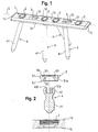
- the bone plate assembly includes a plate member 1 which is in this embodiment a substantially rectangular body with a top side 1a, a bottom side 1b, short sides 1c and long sides 1d and a longitudinal axis L.
- a plurality of first holes 2 extend through the plate member from the top side 1a to the bottom side 1b.
- Second holes 3 can be provided which are, for example, arranged between the first holes 2 also extend from the top side 1a to the bottom side 1b.
- the number and arrangement of first and second holes can vary according to the size and shape of the plate member 1.
- the plate member may have only first holes 2 and the second holes 3 can be omitted.
- the bone plate assembly further comprises a plurality of bone anchors in form of bones screws 4 which can be inserted into the first holes 2 and/or the second holes 3.
- the bone screw 4 has a threaded shank 41 with a tip and a head 42.
- the head 42 has a spherical exterior surface portion and a recess 42a at its free end 42b opposite to the shank 41 for engagement with a screw driver.
- Other longitudinal bone anchors like pins, barbed or roughened nails can also be used.
- a locking element 5 is provided for locking the bone screw 4 in the first holes 2 as described below.
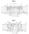
- the structure of the first holes 2 will now be described with reference to a first hole 2 shown in Figs. 3 and 4 .
- the first hole 2 comprises an opening 20 at the bottom side 1b the inner diameter of which is larger than the outer diameter of the threaded shank 41 of the bone screw so that the threaded shank 41 can pass therethrough.
- the diameter is, however, smaller than the largest outer diameter d of the head 42 so that the head 42 cannot pass therethrough.
- Adjacent the opening 20 a hollow seat portion 21 is provided which forms a socket for a pivoting movement of the head 42. This allows insertion of the bone screw at any desired angle.
- the seat portion 21 is spherically-shaped with a radius that matches the radius of the spherically-shaped portion of the head 42.
- the height h of the seat portion 21 is smaller than the radius of the head 42 and preferably smaller than half of, more preferably smaller than or equal to a quarter of the radius of the head 42.
- a cylindrical bore 22 with a portion 23 having an internal thread is provided between the seat portion 21 and the top side 1a . As shown in Fig. 3 , in one exemplary aspect of the invention, this internal thread is a full thread, reaching to the top of the cylindrical bore 22.
- the inner diameter of the bore 22 is larger than the inner diameter of the seat portion 21 and larger than the outer diameter of the spherical portion of the head 42.
- the inner diameter D of the bore 22 is larger than the outer diameter d of the head 42.
- the inner diameter D of the bore 22 may, in one exemplary aspect of the invention, be approximately 1.2 to 1.7 times larger than the maximum outer diameter d of the head 42.
- the threaded portion 23 can have any thread form, for example a metric thread.
- the thickness 1 of the plate member 1 at the hole that means the distance of the top side 1a from the bottom side 1b is smaller or equal to the largest outer diameter d of the head 42.
- the opening 20 widens in a conical portion 24 towards the bottom side 1b to allow even larger pivot angles of the bone screw 4.
- the locking element 5 is substantially cylindrical and has a top side 5a and a bottom side 5b and a threaded exterior surface portion 51 which cooperates with the internally threaded portion 23 of the bore 22 of the plate member.
- the height of the locking element corresponds substantially to the depth of the bore 22 so that when the locking element 5 is screwed into the bore 22 its top side 5a is substantially flush with the top side 1a of the plate member.
- the locking element is partially threaded.
- the non-threaded portion 51a has an axial length which may be about equal to or smaller than that of the threaded portion 51.
- the locking element can also be fully threaded.
- the locking element 5 comprises preferably a spherically-shaped recess 52 which fits to the spherically-shaped portion of the head 42.
- the depth of the recess 52 can be equal to or larger than the radius of the spherical portion of the head 42.
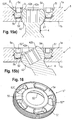
- a recess 53 in form of a ring-shaped groove with a contour which allows a form-fit engagement of a corresponding tool which is provided in the outer radial area is provided in the top side 5a of the locking element 5.
- the contour of the groove in this embodiment has a star-like shape.
- the central area of the top side 5a is solid, i.e. is without a recess.
- the depth of b of the recess 53 is larger than the distance a of the deepest portion of the recess 52 from the top side 5a. Since the recess 53, which serves for engagement with a driver, is in the outer area of the top side 5a, the spherical recess 53 extending from the bottom side 5b can have a large depth which results in an increased contact area between the locking element 5 and the head 42. On the other hand, the seat portion 21 can be kept small to allow large angulation of the bone screw 4.
- the locking element has a reduced height.
- the overall height of the bone plate assembly can be kept small.
- Frictional locking allows pivoting under application of an additional force which exceeds the frictional force between head and plate member.
- a further different locking element may have a length or a different depth in the spherically-shaped recess which allows a free pivotal movement of the screw with the locking element only preventing pull-out of the screw.
- the overall height of the bone plate assembly can be further downsized by using a two-start thread for the threaded portions.
- the seat portion 21 needs not to be spherically-shaped, but can have another shape such as a taper or even can be realized only by the edge of the opening 20. Between the seat portion 21 and the bore 22 transitional sections of the hole can be arranged provided they do not restrict the pivoting motion of the screw head.
- the bore 22 is shown to be cylindrically-shaped. However, it could also be a conical bore.
- the locking element would then be adapted thereto. Since only a relatively small clamping force is necessary to lock the angular position of the bone screw, other kinds of connections between the locking element and the bore can be used, for example, a bayonet locking structure.
- the orientation of the holes in vertical direction needs not to be perpendicular to the surface but can include an angle with the normal onto the surface of the plate member for providing an initial angulation.
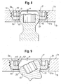
- the locking element 5 is slightly modified in such a way that the recess 53 is closer to the outer edge than in the locking element 5 shown in Fig. 4 .
- the recess 52' is deeper than the recess 52 of the locking element of Fig. 4 and has a flat portion near the top side 5a.
- the profile of the assembly can be further downsized by this design.
- the recess 53 forms a drive portion for a tool such as a screw driver. It is not restricted to the shown star-like contour but can also have other shapes such as, for example, a polygon, a wavy or a flower-like contour or can have interruptions so that only groove portions or recesses are provided.
- the second holes 3 have a substantially oblong shape with the long side oriented in the direction of the longitudinal axis L.
- a hole 3 has an upper seat portion 31 which has the shape of a hollow spherical section matching the exterior spherical surface portion of the head 42.
- a lower seat portion 32 is provided at the opposite short side of the oblong hole 3 adjacent the bottom side 1b.
- the shape of the seat portion 32 is also spherical and matches the shape of the exterior surface portion of the head 42.
- an inclined spherical groove 33 extends along the inner wall of the long side of the oblong hole, the size of which is adapted to the exterior surface portion of the head 42 so that the head 42 can be guided along the groove 33.
- the elements of the bone plate assembly are made of a body compatible material, such as a body compatible metal, for example stainless steel or titanium or a body compatible metal alloy such as Ni-Ti alloys, for example Nitinol, or of a body compatible plastic material, for example medical grade PEEK or of combinations thereof.
- a body compatible material such as a body compatible metal, for example stainless steel or titanium or a body compatible metal alloy such as Ni-Ti alloys, for example Nitinol, or of a body compatible plastic material, for example medical grade PEEK or of combinations thereof.
- the plate member, the locking elements and the bone anchors can be made of different materials.
- the number of bone screws necessary for the stabilization of the bone parts or bone fragments is determined. It should be noted that in some cases it is not necessary to use all the holes provided on the plate member. Holes which are not used for bone screws may be closed by a plug member to be described below. Once, the necessary number and types of the screws are determined, the screws are inserted into the first holes 2 and/or second holes 3. After positioning the plate member at the fracture site the screws are inserted into the bone parts at the desired angle. The bone screws are inserted into the holes at this desired angle and the spherical seat allows placement of the head of the screw in the hole at this angle.
- the head 42 of each bone screw After full insertion of bone screws the head 42 of each bone screw, which is inserted into a first hole 2, abuts against the seat portion 21 of the hole 2. Already in this condition the angle between the bone screw and the plate member is fixed when at least two bone screws are inserted.
- the locking element 5 can be used which is inserted into the bore and tightened so that it locks the head in the selected angular position. If desired, different locking elements can be applied to different screws in order to provide for full locking, frictional locking or free angulation with the locking member only preventing pull-out of the screw as described above.
- the holes 3 are used for providing a self-compression effect.
- the bone screws 4 which are inserted into the oblong holes 3 are oriented substantially vertically relative to the plate member.
- the screw head 42 which is first seated in the upper seat portion 31 slides downwards along the inclined groove 33 until it rests in the lower seat portion 32.
- the second holes are arranged such that the lower seat portion 32 faces the center of the plate member. Since the screw head 42 is fixedly connected to the threaded shank 41 which is screwed into the bone the movement of the head 42 along the groove 33 leads to a movement of the bone part or fragment relative the plate and as a result to a compression of the bone parts against each other and against the plate member.
- FIG. 12 the plate member 1' has a contoured shape.
- the outer contour in a top view is slightly trapezoidal with rounded corners and a broadened middle portion.
- spherically shaped recesses 7 are provided at the lower side 1b to reduce the contact area with the bone. A minimal contact area of the plate member with the bone surface may be required in certain cases to prevent injury of the bone surface and compression of blood vessels etc.
- the recesses 7 also result in plate member portions with different thickness.
- the plate can be bent in portions with a smaller thickness the bone plate assembly can be used as a dynamic compression plate.
- two holes are provided at the short sides 1c and three holes are provided in the center of the plate in a longitudinal direction.
- the holes 2 may be offset from the longitudinal axis. The number is not limited to the number shown but can vary. Between the holes 2 near the short sides 1c and the holes 2 in the center second holes 3 may be provided for self-compression.
- the first holes 2 in the center section of the plate member are not used for screws. They may be closed by a plug member 8 shown in Fig. 14 .
- the plug member 8 is substantially cylindrical with a top side 8a and a bottom side 8b. It has a first portion 81 which has a threaded portion 82 cooperating with the threaded portion 23 of the bore 22. The first portion 81 fits into the bore 22 so that the top surface 8a is substantially flush with the top surface 1a of the plate member 12'.
- a recess 53 which has an approximate star-shape is provided in the top surface 8a of the plug member as for the locking element 5.
- the plug member can prevent cracking or breaking of a plate member at the thinned portions 7.
- the plug member 8 Adjacent the cylindrical portion 81 the plug member 8 has a spherically shaped projection 83 which fits into the seat portion 21 of the hole 2 so that after insertion of the plug member 8 the hole 2 is closed.
- the bottom side 8d may be flush with the bottom side 1b of the plate member.
- a locking element as described above can be used as a plug member.
- the bone plate assembly includes a modified locking element as shown in Figs. 15a ), 15b).
- the locking element 5' differs from the locking element of the previous embodiments by the shape of the recess 53''' at the top side 5a of the locking element which serves for the driver.
- a coaxial through-hole 54 is provided. All other features of the locking element are the same or can be present in the same manner as for the locking element of the previous embodiments.
- the coaxial through-hole 54 extends from the top side 5a through the locking element and continuous in the recess 52.
- the diameter of the coaxial through-hole is configured. Hence, the diameter of the through-hole can be larger than the diameter of the free end 42b of the screw head 42.
- the coaxial through hole 54 allows to further reduce the thickness of the plate member and the locking element, since the head of the screw can partially extend into the hole when the screw is in an angled position as shown in Fig. 15b )
- the recess for the driver which is used to tighten the locking element 5' is in this embodiment composed of a plurality of spaced apart recesses forming elongate pockets 53''' which are arranged around the central axis of the locking element in a circumferential manner.
- the depth of the pockets 53''' is configured such that the pockets extend below the free end 42b of the screw head when the screw head 42 rests in the seat 21.
- the distance b of the deepest portion of the pockets 53" from the top side 1a is larger than the deepest portion of the recess 52 from the top side 1a in the previous embodiments. Since the recess 53" extends into the body of the locking element in an area around the screw head the locking element has a small thickness. Therefore, a low profile polyaxial locking plate is provided. In a modified embodiment the recess may extend completely through the locking element.
- the locking element 5" has an annular rim 55 on the top side 5a.
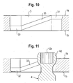
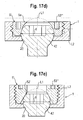
- FIGs. 17a) to 17e schematic sectional views of a portion of the bone plate assembly with a polyaxial bone screw and a locking element are shown that explain a dimensional relationship of the recess for the driver and the head of the bone screw.
- a locking element is shown wherein the recess 52 for the head extends into the top side 5a so that a through-hole 54 is formed.
- a first level L1 is defined by the highest point of a circle that is drawn around the screw head with a diameter that corresponds to the largest diameter d of the screw head.
- the largest diameter d of the screw head 42 is located above the opening 20 on the bottom side of the bone plate.
- the bottom of the recess 53''' for the driver defines a second level L2.
- the level L2 is below L1. With this relationship the bone plate assembly has a low profile. Simultaneously, a large range of angulation of the screw can be achieved.
- the locking element is similar to the locking element shown in Fig. 16 and has an annular rim 55 at the top side. Also in this case, the highest point of a circle which is projected from the position of the greatest diameter d of the screw head defines a level L1 and the bottom of the recess 53''' defines a level L2 which is below L1.
- Fig. 17c shows a locking element that has the highest point of a circle projected from the position with the largest diameter d of the screw head 42 on a level L1 which is on the same level L2 as the bottom of the recess 53''' for the driver. A low profile can still be obtained.
- Fig. 17d the top surface 5a of the locking element is closed.
- the highest point of the circle is above the closed top surface.
- the level L2 is below L1.
- Fig. 17e shows a locking element which has a conically-shaped first recess 52' which contacts the head 42 of the polyaxial bone screw 4. Also in this case the level L2 is the same as the level L1 or below L1.
- the contact area between the screw head 42 and the recess 52 is not limited to a spherical surface, it can be a line contact or can have another shape.
- the recess 52 for the screw head is not limited to a spherical or a conical form but can have various shapes.
- the screw head needs not to be completely spherical. It is sufficient that it has a spherically shaped surface portion. It can also be shaped otherwise, as long as it can pivot in the seat.
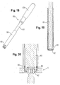
- Figs. 18 to 20 show a tool for use with locking element and the bone plate assembly.
- the tool 60 comprises a driver 61 with an engagement portion 62 for engaging the locking element and a handle 63.
- the engagement portion 62 of the driver 61 is configured to engage the engagement structure such as the pockets 53''' in the locking element 5' of Figs. 15 and 16 or the groove 53 in the locking element 5 of Figs. 1 to 9 .
- the driver 61 extends with its engagement portion 62 through a tubular holder 64 and is axially movable and rotatable therein.
- the holder 64 has at a distance from its free end which faces away from the handle 63 a radial slot 65 which is configured to pass the locking element 5 therethrough.
- the counter holder 64 has at its free end a portion with an internal thread 66 cooperating with the external thread 51 of the locking element 5.
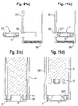
- Figs. 21a) to 21d The steps of taking up the locking element with the tool 60 are schematically shown in Figs. 21a) to 21d ). Exemplary the locking element of Fig. 15 and 16 is shown.
- the driver 61 is retracted and the holder 64 is free at the location of the slot 65.
- the locking element 5' is introduced through the slot 65 into the holder 64.
- the bottom side 5b of the locking element which has the recess 52 for the head, faces the threaded portion 66 of the holder 64. Then, as shown in Fig.
- the driver 61 is moved through the holder 64 to engage the pockets 53''' and the locking element 5' is screwed into the threaded portion 66 of the holder 64. Then, as shown in Fig. 21d ), the driver 61 can be retracted and the locking element can be placed into the hole 2. Finally, as shown in Fig. 20 before, the driver 61 can be advanced again and engage the pockets 53''' of the locking element to screw the locking element further into the hole 2. If desired, the locking element is tightened to press onto the head to fix the angular position of the bone screw.
- the locking element can be safely taken up and held in the holder. In addition, it can be safely placed into the hole and inserted therein.
- the locking element may be configured to be used with a polyaxial bone anchor, and be substantially cylindrical with a bottom side (5b) facing a head (42) of the bone anchor, a top side (5a) opposite to the bottom side (5b), and a surface portion with an external thread.
- the locking element may have a first recess (52, 52') at the bottom side for accommodating at least a portion of the head (42), and a second recess (53, 53', 53''') at the top side (5a) for engagement with a driver, the second recess being located outside the center of the top side (5a).
- the head (42) may have a portion with a largest diameter (d), and a first level L1 defined by the highest point of a circle with the largest diameter drawn around the head, and a second level L2 is defined by the bottom of the second recess (53, 53', 53'''), L2 being at a level not higher than L1.
- the locking element may include a coaxial through-hole (54).
- a contact area of the first recess (52) that contacts the head may be a conically shaped contact, a line contact, and/or a spherically-shaped contact.
- the second recess (53, 53", 53") may be located substantially in a radially outer area of the top side (5a).
- the second recess (53, 53') may include a ring-shaped groove with a contour configured have form-fitting engagement with the driver.
- the contour may be selected from at least one of the group consisting of a star-like contour, a polygonal contour, and a flower-like contour.
- the second recess may include a plurality of pockets (53''').
- the pockets may be configured to extend through the locking element into the bottom side (5b).
- a distance (a) of a deepest portion of the second recess (52), measured from the top side (5a) is smaller than a depth (b) of the first recess (53, 53', 53") measured from the top side (1a).
- the locking element may also include a portion (51) with an external thread.
- the locking element (5) may include a portion with the external thread that spans the entire locking element (5), making the locking element (5) fully threaded, and/or a portion with the external thread that does not span the entire locking element (5), having a non-threaded section (51a) adjacent the bottom side (5b).
- An axial length of the non-threaded section (51a) may be substantially equal to or smaller than the axial length of a threaded section of the portion with the external thread (51).
- a bone plate assembly may include an elongate plate member (1, 1') with a top side (1a) and a bottom side (1b), at least two holes (2, 2, 3) extending from the top side to the bottom side, and at least two bone anchors (4), each bone anchor comprising a shank (41) configured to anchor into the bone, and a head (42) having a portion with a largest outer diameter (d), wherein the shank is extendable through the hole.
- At least one of the holes (2) may be configured to define a seat (21) at the bottom side (1b) adapted to pivotably receive the head (42), wherein the at least one of the holes (2) includes a bore (22) at the top side (1a) with a bore axis and an inner diameter (D) at least as large as the largest diameter (d) of the head (42).
- the locking element (5, 5', 5", 5''') may be configured to be inserted into the bore (22), having a central axis coaxial with the bore axis, a bottom side (5b) facing the head, and a top side (5a) facing away from the head.
- the locking element may have a first recess (52, 52') at the bottom side for at least partially covering the head, and a second recess (53, 53', 53''') at the top side (5a) for engagement with a driver, the second recess being located outside the center of the top side (5a).
- the highest point of a circle with the largest diameter (d) that is drawn around the head may define a first level L1 and the bottom of the second recess (53, 53', 53''') may define a second level L2, which is at a level not higher than L1.
- the bone plate assembly may include a plurality of locking elements and these may be configured to lock the head and/or prevent loosening of the bone anchoring element and/or bone plate assembly, while allowing pivotal movement.
- a bone plate assembly may include an elongate plate member (1, 1') with a top side (1a) and a bottom side (1b), at least two holes (2, 2, 3) extending from the top side to the bottom side, and at least two bone anchors (4), each bone anchor comprising a shank (41) configured to anchor into the bone, and a head (42) having a top (42a) and a portion with a largest outer diameter (d), wherein the shank is extendable through the hole.
- At least one of the holes (2) may be configured to define a seat (21) at the bottom side (1b) adapted to pivotably receive the head, (42) wherein the at least one of the holes includes a bore (22) at the top side (1a) with a bore axis and an inner diameter (D) which is at least as large as the largest diameter (d) of the head (42).
- the head may be pivotably received when a bone anchor is inserted into the bone plate assembly, for example. However, at such times as, for example, upon insertion of the bone anchor into bone, pivoting may be restricted.
- a locking element (5, 5') is configured to be inserted into the bore and having a central axis coaxial with the bore axis, a bottom side (5b) facing the head, a top side (5a) facing away from the head and a recess (53, 53', 53''') at the top side (5a) configured to be engaged with a driver, the recess being located outside the center of the top side (5a) and having a depth that extends below the top (42a) of the screw head (42) when the screw head (42) is in the seat (21).
- the bore may have a portion (23) with an internal thread and the locking element (5) may have a portion (51) with an external thread adapted to cooperate with the internal thread of the bore. At least one of the internal thread and the external thread may include a two-start thread. Furthermore, another locking element may be included in the bone plate assembly, and the locking element and the another locking element may have different axial lengths.
- the first recess (52) may include a spherical shape and a depth measured from the bottom side (5b) substantially equal to or slightly larger than half of the diameter (d) of the head..
- the bone plate assembly may also include a plug member (8) adapted to close a hole if a bone anchor is not used.
- a tool adapted for use with a locking element and/ or a bone plate assembly described herein may include a driver (61) with an engagement portion (62) configured to engage a locking element; and a tubular holder (64).
- the driver may be configured to extend with the engagement portion (62) through the tubular holder (64), and may be axially movable and rotatable within the holder.
- the holder may have a radial slot (65) adapted for insertion of the locking element.
- the holder may include a portion with an internal thread (66) for cooperation with an external thread (51) of the locking element.
- the shape of the plate member is not restricted to the embodiments shown. Other shapes are also conceivable.
- the bone anchor is not limited to a bone screw which has a threaded shank. Smooth, barbed or roughened pins are also conceivable. Further, any known bone screws may be used. Additionally, other bone anchors may be used.
Landscapes
- Health & Medical Sciences (AREA)
- Orthopedic Medicine & Surgery (AREA)
- Life Sciences & Earth Sciences (AREA)
- Surgery (AREA)
- Medical Informatics (AREA)
- Engineering & Computer Science (AREA)
- Biomedical Technology (AREA)
- Heart & Thoracic Surgery (AREA)
- Nuclear Medicine, Radiotherapy & Molecular Imaging (AREA)
- Molecular Biology (AREA)
- Animal Behavior & Ethology (AREA)
- General Health & Medical Sciences (AREA)
- Public Health (AREA)
- Veterinary Medicine (AREA)
- Neurology (AREA)
- Surgical Instruments (AREA)
Priority Applications (1)
| Application Number | Priority Date | Filing Date | Title |
|---|---|---|---|
| EP15203135.7A EP3028655B1 (en) | 2010-03-08 | 2011-03-04 | Locking element for a polyaxial bone anchor, bone plate assembly and tool |
Applications Claiming Priority (5)
| Application Number | Priority Date | Filing Date | Title |
|---|---|---|---|
| US31151710P | 2010-03-08 | 2010-03-08 | |
| EP10158246 | 2010-03-29 | ||
| US36949510P | 2010-07-30 | 2010-07-30 | |
| EP11714657.1A EP2544614B1 (en) | 2010-03-08 | 2011-03-04 | Locking element for a polyaxial bone anchor, bone plate assembly and tool |
| EP15203135.7A EP3028655B1 (en) | 2010-03-08 | 2011-03-04 | Locking element for a polyaxial bone anchor, bone plate assembly and tool |
Related Parent Applications (2)
| Application Number | Title | Priority Date | Filing Date |
|---|---|---|---|
| EP11714657.1A Division EP2544614B1 (en) | 2010-03-08 | 2011-03-04 | Locking element for a polyaxial bone anchor, bone plate assembly and tool |
| EP11714657.1A Division-Into EP2544614B1 (en) | 2010-03-08 | 2011-03-04 | Locking element for a polyaxial bone anchor, bone plate assembly and tool |
Publications (2)
| Publication Number | Publication Date |
|---|---|
| EP3028655A1 EP3028655A1 (en) | 2016-06-08 |
| EP3028655B1 true EP3028655B1 (en) | 2017-11-22 |
Family
ID=43927910
Family Applications (2)
| Application Number | Title | Priority Date | Filing Date |
|---|---|---|---|
| EP15203135.7A Active EP3028655B1 (en) | 2010-03-08 | 2011-03-04 | Locking element for a polyaxial bone anchor, bone plate assembly and tool |
| EP11714657.1A Active EP2544614B1 (en) | 2010-03-08 | 2011-03-04 | Locking element for a polyaxial bone anchor, bone plate assembly and tool |
Family Applications After (1)
| Application Number | Title | Priority Date | Filing Date |
|---|---|---|---|
| EP11714657.1A Active EP2544614B1 (en) | 2010-03-08 | 2011-03-04 | Locking element for a polyaxial bone anchor, bone plate assembly and tool |
Country Status (7)
Families Citing this family (53)
| Publication number | Priority date | Publication date | Assignee | Title |
|---|---|---|---|---|
| US8007522B2 (en) | 2008-02-04 | 2011-08-30 | Depuy Spine, Inc. | Methods for correction of spinal deformities |
| WO2010135537A2 (en) * | 2009-05-20 | 2010-11-25 | Synthes Usa, Llc | Patient-mounted retraction |
| US8808333B2 (en) * | 2009-07-06 | 2014-08-19 | Zimmer Gmbh | Periprosthetic bone plates |
| US8808335B2 (en) * | 2010-03-08 | 2014-08-19 | Miami Device Solutions, Llc | Locking element for a polyaxial bone anchor, bone plate assembly and tool |
| CA2839423A1 (en) | 2011-06-15 | 2012-12-20 | Smith & Nephew, Inc. | Variable angle locking implant |
| WO2013028951A1 (en) | 2011-08-25 | 2013-02-28 | Synthes Usa, Llc | Peek or pmma transparent implant comprising an adhesive layer of an uncured polymer. |
| CA2847519C (en) * | 2011-09-14 | 2019-06-18 | Zimmer Gmbh | Bone fixing apparatus |
| US9782204B2 (en) | 2012-09-28 | 2017-10-10 | Medos International Sarl | Bone anchor assemblies |
| US20140277153A1 (en) | 2013-03-14 | 2014-09-18 | DePuy Synthes Products, LLC | Bone Anchor Assemblies and Methods With Improved Locking |
| US10342582B2 (en) | 2013-03-14 | 2019-07-09 | DePuy Synthes Products, Inc. | Bone anchor assemblies and methods with improved locking |
| US9259247B2 (en) | 2013-03-14 | 2016-02-16 | Medos International Sarl | Locking compression members for use with bone anchor assemblies and methods |
| US9724145B2 (en) | 2013-03-14 | 2017-08-08 | Medos International Sarl | Bone anchor assemblies with multiple component bottom loading bone anchors |
| US9775660B2 (en) | 2013-03-14 | 2017-10-03 | DePuy Synthes Products, Inc. | Bottom-loading bone anchor assemblies and methods |
| EP4338708A3 (en) * | 2013-12-02 | 2024-06-19 | Zimmer, Inc. | Adjustable orthopedic connections |
| EP3082632A4 (en) * | 2013-12-20 | 2018-01-10 | Crossroads Extremity Systems, LLC | Polyaxial locking hole |
| WO2016007624A1 (en) | 2014-07-10 | 2016-01-14 | Orthodiscovery Group Llc | Bone implant and means of insertion |
| EP2932927B1 (en) | 2014-04-17 | 2017-09-20 | Biedermann Technologies GmbH & Co. KG | Bone plate with enlarged angle of inclination for a bone anchor to a favored side |
| AU2015258930A1 (en) * | 2014-05-15 | 2016-11-24 | Smith & Nephew, Inc. | Tissue graft fixation with tension adjustment |
| FR3023469B1 (fr) * | 2014-07-10 | 2016-08-26 | In2Bones | Implant et kit chirurgical pour maintenir en position des corps osseux d'un patient les uns par rapport aux autres |
| US11202626B2 (en) | 2014-07-10 | 2021-12-21 | Crossroads Extremity Systems, Llc | Bone implant with means for multi directional force and means of insertion |
| US9987043B2 (en) | 2014-10-24 | 2018-06-05 | Stryker European Holdings I, Llc | Methods and systems for adjusting an external fixation frame |
| CN105877831B (zh) * | 2015-02-18 | 2020-09-25 | 比德尔曼技术有限责任两合公司 | 骨板 |
| AU2016294449B2 (en) | 2015-07-13 | 2018-03-22 | Crossroads Extremity Systems, Llc | Bone plates with dynamic elements |
| US10368913B2 (en) * | 2015-08-10 | 2019-08-06 | Stryker European Holdings I, Llc | Adjustment instrument with tactile feedback |
| US9877839B2 (en) | 2015-08-25 | 2018-01-30 | Wright Medical Technology, Inc. | Modular talar fixation method and system |
| US10993750B2 (en) | 2015-09-18 | 2021-05-04 | Smith & Nephew, Inc. | Bone plate |
| WO2017113015A1 (en) | 2015-12-29 | 2017-07-06 | Godbout Joseph Daniel Paul | Fastener with pivoting head |
| US20170181779A1 (en) * | 2015-12-29 | 2017-06-29 | Orthohelix Surgical Designs, Inc. | Active compression plate and method for its use |
| CN109788960B (zh) | 2016-08-15 | 2022-03-08 | 因奎创新有限责任公司 | 骨融合装置、系统和方法 |
| JP7069178B2 (ja) | 2017-01-09 | 2022-05-17 | ジンマー,インコーポレイティド | 調節可能な整形外科的接続 |
| US11864753B2 (en) | 2017-02-06 | 2024-01-09 | Crossroads Extremity Systems, Llc | Implant inserter |
| WO2018148284A1 (en) | 2017-02-07 | 2018-08-16 | Crossroads Extremity Systems, Llc | Counter-torque implant |
| EP3375394B1 (en) | 2017-03-13 | 2021-10-13 | Biedermann Technologies GmbH & Co. KG | Cable retaining insert and bone plate assembly with such a cable retaining insert |
| US10925658B2 (en) | 2017-04-21 | 2021-02-23 | Zimmer, Inc. | Guide wire alignment |
| US10849690B2 (en) | 2017-04-21 | 2020-12-01 | Zimmer, Inc. | Tool for fixed customised relative alignment of adjustable orthopedic devices |
| USD928589S1 (en) * | 2018-02-12 | 2021-08-24 | Bematrix Bvba | Pin plate |
| US11013541B2 (en) * | 2018-04-30 | 2021-05-25 | DePuy Synthes Products, Inc. | Threaded locking structures for affixing bone anchors to a bone plate, and related systems and methods |
| US10828076B2 (en) | 2018-05-17 | 2020-11-10 | Biedermann Technologies Gmbh & Co. Kg | Bone fixation assembly with enlarged angle of inclination for a bone anchor to a favored side |
| US10765461B2 (en) * | 2018-06-01 | 2020-09-08 | DePuy Synthes Products, Inc. | Variable angle bone fixation device |
| CN109009379B (zh) * | 2018-08-23 | 2023-10-03 | 常州市武进人民医院 | 微动式骨折内固定系统及其使用的骨折用微动螺钉 |
| AU2019346607B2 (en) * | 2018-09-27 | 2025-06-26 | Triqueue Holdings, Llc | Implant systems, plates, bone fusion systems, and methods employing same |
| US11160592B2 (en) * | 2018-10-18 | 2021-11-02 | Biedermann Technologies Gmbh & Co. Kg | Method of using bone plate with polyaxial injection screws |
| JP7281160B2 (ja) * | 2018-10-30 | 2023-05-25 | 株式会社ホムズ技研 | 骨固定システム |
| EP3656320B1 (en) | 2018-11-20 | 2022-08-24 | Biedermann Technologies GmbH & Co. KG | Anchoring member for a polyaxial bone anchoring device and polyaxial bone anchoring device with such an anchoring member |
| US11432856B2 (en) | 2019-02-28 | 2022-09-06 | Biedermann Technologies Gmbh & Co. Kg | Bone plate with accessory elements attached at bone fastener holes |
| KR102348490B1 (ko) * | 2019-06-13 | 2022-01-07 | 고려대학교 산학협력단 | 골 접합용 임플란트 결합구조 |
| EP3785649B1 (en) * | 2019-08-30 | 2022-08-03 | Biedermann Technologies GmbH & Co. KG | Bone anchoring device |
| BR112022016152A2 (pt) * | 2020-02-14 | 2022-10-04 | Paragon 28 Inc | Tampas de orifício de placa óssea, sistemas de placa óssea e métodos usando os mesmos . |
| US12059183B2 (en) * | 2020-07-31 | 2024-08-13 | Crossroads Extremity Systems, Llc | Bone plates with dynamic elements and screws |
| USD961081S1 (en) | 2020-11-18 | 2022-08-16 | Crossroads Extremity Systems, Llc | Orthopedic implant |
| WO2022184797A1 (en) | 2021-03-05 | 2022-09-09 | Medos International Sarl | Selectively locking polyaxial screw |
| WO2024056760A1 (en) * | 2022-09-13 | 2024-03-21 | Medos International Sarl | Surgical implant instruments |
| USD1084805S1 (en) * | 2023-09-28 | 2025-07-22 | Gunnersbury Global Trade, Ltd. | Fastening device |
Family Cites Families (50)
| Publication number | Priority date | Publication date | Assignee | Title |
|---|---|---|---|---|
| US2813450A (en) * | 1954-05-03 | 1957-11-19 | Dzus William | Rotatable fastener having circular toothed tool receiving groove |
| US4480513A (en) * | 1981-11-16 | 1984-11-06 | Mcgard, Inc. | Bolt-lock structure |
| US5180381A (en) * | 1991-09-24 | 1993-01-19 | Aust Gilbert M | Anterior lumbar/cervical bicortical compression plate |
| US5370486A (en) * | 1991-12-19 | 1994-12-06 | Plummer; Mark J. | Vehicle locking fastener assembly |
| US5814046A (en) | 1992-11-13 | 1998-09-29 | Sofamor S.N.C. | Pedicular screw and posterior spinal instrumentation |
| FR2697991B1 (fr) * | 1992-11-13 | 1995-02-03 | Fabrication Mat Orthopedique S | Instrumentation d'ostéosynthèse lombosacrée pour la correction du spondylolisthésis par voie postérieure, et vis d'instrumentation. |
| US5534027A (en) * | 1993-06-21 | 1996-07-09 | Zimmer, Inc. | Method for providing a barrier to the advancement of wear debris in an orthopaedic implant assembly |
| US5674222A (en) * | 1994-06-01 | 1997-10-07 | Synthes (U.S.A.) | Forked plate |
| JP3501542B2 (ja) | 1995-04-07 | 2004-03-02 | 富久 腰野 | 医用硬組織代替部材および人工関節 |
| US5520690A (en) * | 1995-04-13 | 1996-05-28 | Errico; Joseph P. | Anterior spinal polyaxial locking screw plate assembly |
| FR2748387B1 (fr) | 1996-05-13 | 1998-10-30 | Stryker France Sa | Dispositif de fixation osseuse, en particulier au sacrum, en osteosynthese du rachis |
| US5885286A (en) * | 1996-09-24 | 1999-03-23 | Sdgi Holdings, Inc. | Multi-axial bone screw assembly |
| CA2279938C (en) | 1997-02-11 | 2006-01-31 | Gary Karlin Michelson | Skeletal plating system |
| ATE224679T1 (de) | 1997-06-12 | 2002-10-15 | Sulzer Orthopaedie Ag | Befestigungssystem für metallische stützschalen |
| US5954722A (en) | 1997-07-29 | 1999-09-21 | Depuy Acromed, Inc. | Polyaxial locking plate |
| EP0933065A1 (de) * | 1998-02-02 | 1999-08-04 | Sulzer Orthopädie AG | Schwenkbares Befestigungssystem an einer Knochenschraube |
| FR2780631B1 (fr) | 1998-07-06 | 2000-09-29 | Dimso Sa | Dispositif d'osteosynthese rachidienne pour fixation anterieure avec plaque |
| US5904683A (en) | 1998-07-10 | 1999-05-18 | Sulzer Spine-Tech Inc. | Anterior cervical vertebral stabilizing device |
| DE19832513A1 (de) | 1998-07-20 | 2000-02-17 | Impag Gmbh Medizintechnik | Befestigungsanordnung |
| EP0988833B1 (de) | 1998-09-24 | 2003-10-01 | Centerpulse Orthopedics Ltd. | Osteosyntheseplatte mit mehreren Knochenschrauben |
| US20060041260A1 (en) | 2000-02-01 | 2006-02-23 | Orbay Jorge L | Fixation system with plate having holes with divergent axes and multidirectional fixators for use therethrough |
| US6440135B2 (en) | 2000-02-01 | 2002-08-27 | Hand Innovations, Inc. | Volar fixation system with articulating stabilization pegs |
| US6893444B2 (en) | 2000-02-01 | 2005-05-17 | Hand Innovations, Llc | Bone fracture fixation systems with both multidirectional and unidirectional stabilization pegs |
| US20040153073A1 (en) | 2000-02-01 | 2004-08-05 | Hand Innovations, Inc. | Orthopedic fixation system including plate element with threaded holes having divergent axes |
| US6767351B2 (en) | 2000-02-01 | 2004-07-27 | Hand Innovations, Inc. | Fixation system with multidirectional stabilization pegs |
| JP2002000611A (ja) | 2000-05-12 | 2002-01-08 | Sulzer Orthopedics Ltd | 骨ネジの骨板への結合 |
| DE50014519D1 (de) | 2000-08-24 | 2007-09-06 | Synthes Gmbh | Vorrichtung zur verbindung eines knochenfixationselementes mit einem längsstab |
| US6423068B1 (en) * | 2000-10-18 | 2002-07-23 | Erhard Reisberg | Method and apparatus for mandibular osteosynthesis |
| JP2002291762A (ja) | 2001-03-30 | 2002-10-08 | Robert Reed Shokai Co Ltd | インプラント用止めねじ操作器具及びその使用方法 |
| EP1404243A4 (en) | 2001-06-04 | 2010-05-19 | Warsaw Orthopedic Inc | DYNAMIC ANTERIORES CERVICAL PLATE SYSTEM WITH MOBILE SEGMENTS, INSTRUMENTS AND METHOD FOR INSTALLING THEM |
| US7186256B2 (en) | 2001-06-04 | 2007-03-06 | Warsaw Orthopedic, Inc. | Dynamic, modular, single-lock anterior cervical plate system having assembleable and movable segments |
| US7097645B2 (en) | 2001-06-04 | 2006-08-29 | Sdgi Holdings, Inc. | Dynamic single-lock anterior cervical plate system having non-detachably fastened and moveable segments |
| AUPR546601A0 (en) * | 2001-06-05 | 2001-06-28 | Australian Surgical Design And Manufacture Pty Limited | High tibial osteotomy device |
| US7476228B2 (en) * | 2002-10-11 | 2009-01-13 | Abdou M Samy | Distraction screw for skeletal surgery and method of use |
| US7967850B2 (en) * | 2003-06-18 | 2011-06-28 | Jackson Roger P | Polyaxial bone anchor with helical capture connection, insert and dual locking assembly |
| US6945975B2 (en) * | 2003-07-07 | 2005-09-20 | Aesculap, Inc. | Bone fixation assembly and method of securement |
| WO2005018466A2 (en) * | 2003-08-26 | 2005-03-03 | Endius, Inc. | Access systems and methods for minimally invasive surgery |
| US8002798B2 (en) | 2003-09-24 | 2011-08-23 | Stryker Spine | System and method for spinal implant placement |
| EP1691698A4 (en) * | 2003-12-12 | 2008-12-17 | Integra Lifesciences Corp | BONE FASTENING DEVICES, SYSTEMS, AND METHODS |
| EP1693013A1 (en) * | 2005-02-22 | 2006-08-23 | Kyon | Plate and screws for treatment of bone fractures |
| US20060276793A1 (en) * | 2005-05-26 | 2006-12-07 | Amedica Corporation | Bone fixation plate with self-locking screws |
| FR2917596B1 (fr) | 2007-06-21 | 2010-06-18 | Newdeal | Kit de fixation a usage medical ou chirurgical |
| AU2008306998B2 (en) | 2007-09-26 | 2014-04-10 | Markus Kuster | Bone anchoring device for the operative repair of fractures |
| US8998958B2 (en) | 2007-12-20 | 2015-04-07 | Aesculap Implant Systems, Llc | Locking device introducer instrument |
| US20090210067A1 (en) | 2008-02-20 | 2009-08-20 | Biomet Manufacturing Corp. | Acetabular Cup Fixation |
| WO2010045355A1 (en) * | 2008-10-14 | 2010-04-22 | K2M, Inc. | Semi-constrained screw and spinal plate assembly |
| EP2236101B1 (en) * | 2009-04-03 | 2015-07-08 | Stryker Trauma GmbH | Sonic screw |
| US8808333B2 (en) | 2009-07-06 | 2014-08-19 | Zimmer Gmbh | Periprosthetic bone plates |
| US8808335B2 (en) * | 2010-03-08 | 2014-08-19 | Miami Device Solutions, Llc | Locking element for a polyaxial bone anchor, bone plate assembly and tool |
| JP6500013B2 (ja) * | 2013-05-29 | 2019-04-10 | スパイナル シンプリシティ エルエルシーSpinal Simplicity LLC | 棘突起間インプラントを挿入するための器具 |
-
2011
- 2011-03-03 US US13/039,422 patent/US8808335B2/en active Active
- 2011-03-04 ES ES11714657.1T patent/ES2581830T3/es active Active
- 2011-03-04 JP JP2012556602A patent/JP5760013B2/ja active Active
- 2011-03-04 EP EP15203135.7A patent/EP3028655B1/en active Active
- 2011-03-04 EP EP11714657.1A patent/EP2544614B1/en active Active
- 2011-03-04 WO PCT/IB2011/000457 patent/WO2011110916A1/en active Application Filing
- 2011-03-04 CN CN201180013246.7A patent/CN102883673B/zh active Active
- 2011-03-04 KR KR1020127023423A patent/KR20130052542A/ko not_active Withdrawn
-
2014
- 2014-07-03 US US14/323,717 patent/US10499964B2/en active Active
-
2019
- 2019-11-13 US US16/683,215 patent/US11547458B2/en active Active
-
2022
- 2022-12-07 US US18/076,811 patent/US11925396B2/en active Active
Non-Patent Citations (1)
| Title |
|---|
| None * |
Also Published As
| Publication number | Publication date |
|---|---|
| JP2013521095A (ja) | 2013-06-10 |
| EP3028655A1 (en) | 2016-06-08 |
| US20230145753A1 (en) | 2023-05-11 |
| US20120059425A1 (en) | 2012-03-08 |
| US20150005830A1 (en) | 2015-01-01 |
| CN102883673B (zh) | 2016-03-02 |
| CN102883673A (zh) | 2013-01-16 |
| WO2011110916A1 (en) | 2011-09-15 |
| US11547458B2 (en) | 2023-01-10 |
| EP2544614A1 (en) | 2013-01-16 |
| US10499964B2 (en) | 2019-12-10 |
| US11925396B2 (en) | 2024-03-12 |
| US20200078060A1 (en) | 2020-03-12 |
| ES2581830T3 (es) | 2016-09-07 |
| EP2544614B1 (en) | 2016-05-11 |
| US8808335B2 (en) | 2014-08-19 |
| JP5760013B2 (ja) | 2015-08-05 |
| KR20130052542A (ko) | 2013-05-22 |
Similar Documents
| Publication | Publication Date | Title |
|---|---|---|
| US11925396B2 (en) | Locking element for a polyaxial bone anchor, bone plate assembly and tool | |
| US20220096130A1 (en) | Receiving part for receiving a rod for coupling the rod to a bone anchoring element | |
| EP2570090B1 (en) | Polyaxial bone anchoring device with enlarged pivot angle | |
| EP2559391B1 (en) | Polyaxial bone anchoring system | |
| EP2526881B1 (en) | Receiving part for receiving a rod for coupling the rod to a bone anchoring element and bone anchoring device with such a receiving part | |
| EP2586392B1 (en) | High angulation polyaxial bone anchoring device | |
| US9192417B2 (en) | Monoplanar bone anchoring device with selectable pivot plane | |
| EP2559390A1 (en) | Polyaxial bone anchoring device with enlarged pivot angle | |
| EP2462886A1 (en) | Receiving part for receiving a rod for coupling the rod to a bone anchoring element and a bone anchoring device | |
| EP3437576B1 (en) | Stabilization device for bones or vertebrae | |
| EP3878386B1 (en) | Coupling device for use with a bone anchoring element and bone anchoring device with such a coupling device | |
| US20180161082A1 (en) | Bone Plate with Reorientable Screw Hole and Cover Member | |
| US20220395299A1 (en) | Bone anchoring device | |
| EP3656320B1 (en) | Anchoring member for a polyaxial bone anchoring device and polyaxial bone anchoring device with such an anchoring member |
Legal Events
| Date | Code | Title | Description |
|---|---|---|---|
| PUAI | Public reference made under article 153(3) epc to a published international application that has entered the european phase |
Free format text: ORIGINAL CODE: 0009012 |
|
| AC | Divisional application: reference to earlier application |
Ref document number: 2544614 Country of ref document: EP Kind code of ref document: P |
|
| AK | Designated contracting states |
Kind code of ref document: A1 Designated state(s): AL AT BE BG CH CY CZ DE DK EE ES FI FR GB GR HR HU IE IS IT LI LT LU LV MC MK MT NL NO PL PT RO RS SE SI SK SM TR |
|
| 17P | Request for examination filed |
Effective date: 20160713 |
|
| RBV | Designated contracting states (corrected) |
Designated state(s): AL AT BE BG CH CY CZ DE DK EE ES FI FR GB GR HR HU IE IS IT LI LT LU LV MC MK MT NL NO PL PT RO RS SE SI SK SM TR |
|
| GRAP | Despatch of communication of intention to grant a patent |
Free format text: ORIGINAL CODE: EPIDOSNIGR1 |
|
| INTG | Intention to grant announced |
Effective date: 20170126 |
|
| GRAJ | Information related to disapproval of communication of intention to grant by the applicant or resumption of examination proceedings by the epo deleted |
Free format text: ORIGINAL CODE: EPIDOSDIGR1 |
|
| INTC | Intention to grant announced (deleted) | ||
| GRAP | Despatch of communication of intention to grant a patent |
Free format text: ORIGINAL CODE: EPIDOSNIGR1 |
|
| INTG | Intention to grant announced |
Effective date: 20170807 |
|
| GRAS | Grant fee paid |
Free format text: ORIGINAL CODE: EPIDOSNIGR3 |
|
| GRAA | (expected) grant |
Free format text: ORIGINAL CODE: 0009210 |
|
| AC | Divisional application: reference to earlier application |
Ref document number: 2544614 Country of ref document: EP Kind code of ref document: P |
|
| AK | Designated contracting states |
Kind code of ref document: B1 Designated state(s): AL AT BE BG CH CY CZ DE DK EE ES FI FR GB GR HR HU IE IS IT LI LT LU LV MC MK MT NL NO PL PT RO RS SE SI SK SM TR |
|
| REG | Reference to a national code |
Ref country code: GB Ref legal event code: FG4D |
|
| REG | Reference to a national code |
Ref country code: CH Ref legal event code: EP Ref country code: CH Ref legal event code: NV Representative=s name: NOVAGRAAF INTERNATIONAL SA, CH |
|
| REG | Reference to a national code |
Ref country code: IE Ref legal event code: FG4D |
|
| REG | Reference to a national code |
Ref country code: AT Ref legal event code: REF Ref document number: 947658 Country of ref document: AT Kind code of ref document: T Effective date: 20171215 |
|
| REG | Reference to a national code |
Ref country code: DE Ref legal event code: R096 Ref document number: 602011043699 Country of ref document: DE |
|
| REG | Reference to a national code |
Ref country code: NL Ref legal event code: MP Effective date: 20171122 |
|
| REG | Reference to a national code |
Ref country code: LT Ref legal event code: MG4D |
|
| REG | Reference to a national code |
Ref country code: AT Ref legal event code: MK05 Ref document number: 947658 Country of ref document: AT Kind code of ref document: T Effective date: 20171122 |
|
| PG25 | Lapsed in a contracting state [announced via postgrant information from national office to epo] |
Ref country code: NL Free format text: LAPSE BECAUSE OF FAILURE TO SUBMIT A TRANSLATION OF THE DESCRIPTION OR TO PAY THE FEE WITHIN THE PRESCRIBED TIME-LIMIT Effective date: 20171122 Ref country code: NO Free format text: LAPSE BECAUSE OF FAILURE TO SUBMIT A TRANSLATION OF THE DESCRIPTION OR TO PAY THE FEE WITHIN THE PRESCRIBED TIME-LIMIT Effective date: 20180222 Ref country code: ES Free format text: LAPSE BECAUSE OF FAILURE TO SUBMIT A TRANSLATION OF THE DESCRIPTION OR TO PAY THE FEE WITHIN THE PRESCRIBED TIME-LIMIT Effective date: 20171122 Ref country code: LT Free format text: LAPSE BECAUSE OF FAILURE TO SUBMIT A TRANSLATION OF THE DESCRIPTION OR TO PAY THE FEE WITHIN THE PRESCRIBED TIME-LIMIT Effective date: 20171122 Ref country code: FI Free format text: LAPSE BECAUSE OF FAILURE TO SUBMIT A TRANSLATION OF THE DESCRIPTION OR TO PAY THE FEE WITHIN THE PRESCRIBED TIME-LIMIT Effective date: 20171122 Ref country code: SE Free format text: LAPSE BECAUSE OF FAILURE TO SUBMIT A TRANSLATION OF THE DESCRIPTION OR TO PAY THE FEE WITHIN THE PRESCRIBED TIME-LIMIT Effective date: 20171122 |
|
| PG25 | Lapsed in a contracting state [announced via postgrant information from national office to epo] |
Ref country code: BG Free format text: LAPSE BECAUSE OF FAILURE TO SUBMIT A TRANSLATION OF THE DESCRIPTION OR TO PAY THE FEE WITHIN THE PRESCRIBED TIME-LIMIT Effective date: 20180222 Ref country code: HR Free format text: LAPSE BECAUSE OF FAILURE TO SUBMIT A TRANSLATION OF THE DESCRIPTION OR TO PAY THE FEE WITHIN THE PRESCRIBED TIME-LIMIT Effective date: 20171122 Ref country code: AT Free format text: LAPSE BECAUSE OF FAILURE TO SUBMIT A TRANSLATION OF THE DESCRIPTION OR TO PAY THE FEE WITHIN THE PRESCRIBED TIME-LIMIT Effective date: 20171122 Ref country code: RS Free format text: LAPSE BECAUSE OF FAILURE TO SUBMIT A TRANSLATION OF THE DESCRIPTION OR TO PAY THE FEE WITHIN THE PRESCRIBED TIME-LIMIT Effective date: 20171122 Ref country code: LV Free format text: LAPSE BECAUSE OF FAILURE TO SUBMIT A TRANSLATION OF THE DESCRIPTION OR TO PAY THE FEE WITHIN THE PRESCRIBED TIME-LIMIT Effective date: 20171122 Ref country code: GR Free format text: LAPSE BECAUSE OF FAILURE TO SUBMIT A TRANSLATION OF THE DESCRIPTION OR TO PAY THE FEE WITHIN THE PRESCRIBED TIME-LIMIT Effective date: 20180223 |
|
| PG25 | Lapsed in a contracting state [announced via postgrant information from national office to epo] |
Ref country code: CZ Free format text: LAPSE BECAUSE OF FAILURE TO SUBMIT A TRANSLATION OF THE DESCRIPTION OR TO PAY THE FEE WITHIN THE PRESCRIBED TIME-LIMIT Effective date: 20171122 Ref country code: SK Free format text: LAPSE BECAUSE OF FAILURE TO SUBMIT A TRANSLATION OF THE DESCRIPTION OR TO PAY THE FEE WITHIN THE PRESCRIBED TIME-LIMIT Effective date: 20171122 Ref country code: DK Free format text: LAPSE BECAUSE OF FAILURE TO SUBMIT A TRANSLATION OF THE DESCRIPTION OR TO PAY THE FEE WITHIN THE PRESCRIBED TIME-LIMIT Effective date: 20171122 Ref country code: CY Free format text: LAPSE BECAUSE OF FAILURE TO SUBMIT A TRANSLATION OF THE DESCRIPTION OR TO PAY THE FEE WITHIN THE PRESCRIBED TIME-LIMIT Effective date: 20171122 Ref country code: EE Free format text: LAPSE BECAUSE OF FAILURE TO SUBMIT A TRANSLATION OF THE DESCRIPTION OR TO PAY THE FEE WITHIN THE PRESCRIBED TIME-LIMIT Effective date: 20171122 |
|
| REG | Reference to a national code |
Ref country code: DE Ref legal event code: R097 Ref document number: 602011043699 Country of ref document: DE |
|
| PG25 | Lapsed in a contracting state [announced via postgrant information from national office to epo] |
Ref country code: IT Free format text: LAPSE BECAUSE OF FAILURE TO SUBMIT A TRANSLATION OF THE DESCRIPTION OR TO PAY THE FEE WITHIN THE PRESCRIBED TIME-LIMIT Effective date: 20171122 Ref country code: RO Free format text: LAPSE BECAUSE OF FAILURE TO SUBMIT A TRANSLATION OF THE DESCRIPTION OR TO PAY THE FEE WITHIN THE PRESCRIBED TIME-LIMIT Effective date: 20171122 Ref country code: PL Free format text: LAPSE BECAUSE OF FAILURE TO SUBMIT A TRANSLATION OF THE DESCRIPTION OR TO PAY THE FEE WITHIN THE PRESCRIBED TIME-LIMIT Effective date: 20171122 Ref country code: SM Free format text: LAPSE BECAUSE OF FAILURE TO SUBMIT A TRANSLATION OF THE DESCRIPTION OR TO PAY THE FEE WITHIN THE PRESCRIBED TIME-LIMIT Effective date: 20171122 |
|
| PLBE | No opposition filed within time limit |
Free format text: ORIGINAL CODE: 0009261 |
|
| STAA | Information on the status of an ep patent application or granted ep patent |
Free format text: STATUS: NO OPPOSITION FILED WITHIN TIME LIMIT |
|
| 26N | No opposition filed |
Effective date: 20180823 |
|
| PG25 | Lapsed in a contracting state [announced via postgrant information from national office to epo] |
Ref country code: MC Free format text: LAPSE BECAUSE OF FAILURE TO SUBMIT A TRANSLATION OF THE DESCRIPTION OR TO PAY THE FEE WITHIN THE PRESCRIBED TIME-LIMIT Effective date: 20171122 Ref country code: SI Free format text: LAPSE BECAUSE OF FAILURE TO SUBMIT A TRANSLATION OF THE DESCRIPTION OR TO PAY THE FEE WITHIN THE PRESCRIBED TIME-LIMIT Effective date: 20171122 |
|
| REG | Reference to a national code |
Ref country code: BE Ref legal event code: MM Effective date: 20180331 |
|
| REG | Reference to a national code |
Ref country code: IE Ref legal event code: MM4A |
|
| PG25 | Lapsed in a contracting state [announced via postgrant information from national office to epo] |
Ref country code: LU Free format text: LAPSE BECAUSE OF NON-PAYMENT OF DUE FEES Effective date: 20180304 |
|
| PG25 | Lapsed in a contracting state [announced via postgrant information from national office to epo] |
Ref country code: IE Free format text: LAPSE BECAUSE OF NON-PAYMENT OF DUE FEES Effective date: 20180304 |
|
| PG25 | Lapsed in a contracting state [announced via postgrant information from national office to epo] |
Ref country code: BE Free format text: LAPSE BECAUSE OF NON-PAYMENT OF DUE FEES Effective date: 20180331 |
|
| PG25 | Lapsed in a contracting state [announced via postgrant information from national office to epo] |
Ref country code: FR Free format text: LAPSE BECAUSE OF NON-PAYMENT OF DUE FEES Effective date: 20180331 |
|
| PG25 | Lapsed in a contracting state [announced via postgrant information from national office to epo] |
Ref country code: MT Free format text: LAPSE BECAUSE OF NON-PAYMENT OF DUE FEES Effective date: 20180304 |
|
| PG25 | Lapsed in a contracting state [announced via postgrant information from national office to epo] |
Ref country code: TR Free format text: LAPSE BECAUSE OF FAILURE TO SUBMIT A TRANSLATION OF THE DESCRIPTION OR TO PAY THE FEE WITHIN THE PRESCRIBED TIME-LIMIT Effective date: 20171122 |
|
| PG25 | Lapsed in a contracting state [announced via postgrant information from national office to epo] |
Ref country code: PT Free format text: LAPSE BECAUSE OF FAILURE TO SUBMIT A TRANSLATION OF THE DESCRIPTION OR TO PAY THE FEE WITHIN THE PRESCRIBED TIME-LIMIT Effective date: 20171122 |
|
| PG25 | Lapsed in a contracting state [announced via postgrant information from national office to epo] |
Ref country code: MK Free format text: LAPSE BECAUSE OF NON-PAYMENT OF DUE FEES Effective date: 20171122 Ref country code: HU Free format text: LAPSE BECAUSE OF FAILURE TO SUBMIT A TRANSLATION OF THE DESCRIPTION OR TO PAY THE FEE WITHIN THE PRESCRIBED TIME-LIMIT; INVALID AB INITIO Effective date: 20110304 |
|
| PG25 | Lapsed in a contracting state [announced via postgrant information from national office to epo] |
Ref country code: AL Free format text: LAPSE BECAUSE OF FAILURE TO SUBMIT A TRANSLATION OF THE DESCRIPTION OR TO PAY THE FEE WITHIN THE PRESCRIBED TIME-LIMIT Effective date: 20171122 Ref country code: IS Free format text: LAPSE BECAUSE OF FAILURE TO SUBMIT A TRANSLATION OF THE DESCRIPTION OR TO PAY THE FEE WITHIN THE PRESCRIBED TIME-LIMIT Effective date: 20180322 |
|
| P01 | Opt-out of the competence of the unified patent court (upc) registered |
Effective date: 20230525 |
|
| PGFP | Annual fee paid to national office [announced via postgrant information from national office to epo] |
Ref country code: DE Payment date: 20250326 Year of fee payment: 15 |
|
| PGFP | Annual fee paid to national office [announced via postgrant information from national office to epo] |
Ref country code: GB Payment date: 20250221 Year of fee payment: 15 |
|
| PGFP | Annual fee paid to national office [announced via postgrant information from national office to epo] |
Ref country code: CH Payment date: 20250401 Year of fee payment: 15 |