EP2544614B1 - Locking element for a polyaxial bone anchor, bone plate assembly and tool - Google Patents
Locking element for a polyaxial bone anchor, bone plate assembly and tool Download PDFInfo
- Publication number
- EP2544614B1 EP2544614B1 EP11714657.1A EP11714657A EP2544614B1 EP 2544614 B1 EP2544614 B1 EP 2544614B1 EP 11714657 A EP11714657 A EP 11714657A EP 2544614 B1 EP2544614 B1 EP 2544614B1
- Authority
- EP
- European Patent Office
- Prior art keywords
- locking element
- head
- bone
- recess
- top side
- Prior art date
- Legal status (The legal status is an assumption and is not a legal conclusion. Google has not performed a legal analysis and makes no representation as to the accuracy of the status listed.)
- Active
Links
- 210000000988 bone and bone Anatomy 0.000 title claims description 148
- 230000004323 axial length Effects 0.000 claims description 8
- 238000003780 insertion Methods 0.000 claims description 6
- 230000037431 insertion Effects 0.000 claims description 6
- 238000007906 compression Methods 0.000 description 5
- 239000012634 fragment Substances 0.000 description 5
- 230000000712 assembly Effects 0.000 description 3
- 238000000429 assembly Methods 0.000 description 3
- 230000006835 compression Effects 0.000 description 3
- 239000000463 material Substances 0.000 description 3
- 230000008878 coupling Effects 0.000 description 2
- 238000010168 coupling process Methods 0.000 description 2
- 238000005859 coupling reaction Methods 0.000 description 2
- 238000005336 cracking Methods 0.000 description 2
- 229910001000 nickel titanium Inorganic materials 0.000 description 2
- 239000004696 Poly ether ether ketone Substances 0.000 description 1
- RTAQQCXQSZGOHL-UHFFFAOYSA-N Titanium Chemical compound [Ti] RTAQQCXQSZGOHL-UHFFFAOYSA-N 0.000 description 1
- 208000027418 Wounds and injury Diseases 0.000 description 1
- 229910045601 alloy Inorganic materials 0.000 description 1
- 239000000956 alloy Substances 0.000 description 1
- 238000004873 anchoring Methods 0.000 description 1
- JUPQTSLXMOCDHR-UHFFFAOYSA-N benzene-1,4-diol;bis(4-fluorophenyl)methanone Chemical compound OC1=CC=C(O)C=C1.C1=CC(F)=CC=C1C(=O)C1=CC=C(F)C=C1 JUPQTSLXMOCDHR-UHFFFAOYSA-N 0.000 description 1
- 210000004204 blood vessel Anatomy 0.000 description 1
- 210000003109 clavicle Anatomy 0.000 description 1
- 230000006378 damage Effects 0.000 description 1
- 230000000694 effects Effects 0.000 description 1
- KHYBPSFKEHXSLX-UHFFFAOYSA-N iminotitanium Chemical compound [Ti]=N KHYBPSFKEHXSLX-UHFFFAOYSA-N 0.000 description 1
- 208000014674 injury Diseases 0.000 description 1
- 238000004519 manufacturing process Methods 0.000 description 1
- 239000002184 metal Substances 0.000 description 1
- 229910052751 metal Inorganic materials 0.000 description 1
- 229910001092 metal group alloy Inorganic materials 0.000 description 1
- 230000004048 modification Effects 0.000 description 1
- 238000012986 modification Methods 0.000 description 1
- HLXZNVUGXRDIFK-UHFFFAOYSA-N nickel titanium Chemical compound [Ti].[Ti].[Ti].[Ti].[Ti].[Ti].[Ti].[Ti].[Ti].[Ti].[Ti].[Ni].[Ni].[Ni].[Ni].[Ni].[Ni].[Ni].[Ni].[Ni].[Ni].[Ni].[Ni].[Ni].[Ni] HLXZNVUGXRDIFK-UHFFFAOYSA-N 0.000 description 1
- 210000004197 pelvis Anatomy 0.000 description 1
- 239000004033 plastic Substances 0.000 description 1
- 229920002530 polyetherether ketone Polymers 0.000 description 1
- 210000004872 soft tissue Anatomy 0.000 description 1
- 239000007787 solid Substances 0.000 description 1
- 230000006641 stabilisation Effects 0.000 description 1
- 238000011105 stabilization Methods 0.000 description 1
- 239000010935 stainless steel Substances 0.000 description 1
- 229910001220 stainless steel Inorganic materials 0.000 description 1
- 239000010936 titanium Substances 0.000 description 1
- 229910052719 titanium Inorganic materials 0.000 description 1
Images


Classifications
-
- A—HUMAN NECESSITIES
- A61—MEDICAL OR VETERINARY SCIENCE; HYGIENE
- A61B—DIAGNOSIS; SURGERY; IDENTIFICATION
- A61B17/00—Surgical instruments, devices or methods, e.g. tourniquets
- A61B17/56—Surgical instruments or methods for treatment of bones or joints; Devices specially adapted therefor
- A61B17/58—Surgical instruments or methods for treatment of bones or joints; Devices specially adapted therefor for osteosynthesis, e.g. bone plates, screws, setting implements or the like
- A61B17/68—Internal fixation devices, including fasteners and spinal fixators, even if a part thereof projects from the skin
- A61B17/80—Cortical plates, i.e. bone plates; Instruments for holding or positioning cortical plates, or for compressing bones attached to cortical plates
- A61B17/8033—Cortical plates, i.e. bone plates; Instruments for holding or positioning cortical plates, or for compressing bones attached to cortical plates having indirect contact with screw heads, or having contact with screw heads maintained with the aid of additional components, e.g. nuts, wedges or head covers
- A61B17/8042—Cortical plates, i.e. bone plates; Instruments for holding or positioning cortical plates, or for compressing bones attached to cortical plates having indirect contact with screw heads, or having contact with screw heads maintained with the aid of additional components, e.g. nuts, wedges or head covers the additional component being a cover over the screw head
-
- A—HUMAN NECESSITIES
- A61—MEDICAL OR VETERINARY SCIENCE; HYGIENE
- A61B—DIAGNOSIS; SURGERY; IDENTIFICATION
- A61B17/00—Surgical instruments, devices or methods, e.g. tourniquets
- A61B17/56—Surgical instruments or methods for treatment of bones or joints; Devices specially adapted therefor
- A61B17/58—Surgical instruments or methods for treatment of bones or joints; Devices specially adapted therefor for osteosynthesis, e.g. bone plates, screws, setting implements or the like
- A61B17/68—Internal fixation devices, including fasteners and spinal fixators, even if a part thereof projects from the skin
- A61B17/80—Cortical plates, i.e. bone plates; Instruments for holding or positioning cortical plates, or for compressing bones attached to cortical plates
- A61B17/8052—Cortical plates, i.e. bone plates; Instruments for holding or positioning cortical plates, or for compressing bones attached to cortical plates immobilised relative to screws by interlocking form of the heads and plate holes, e.g. conical or threaded
- A61B17/8057—Cortical plates, i.e. bone plates; Instruments for holding or positioning cortical plates, or for compressing bones attached to cortical plates immobilised relative to screws by interlocking form of the heads and plate holes, e.g. conical or threaded the interlocking form comprising a thread
-
- A—HUMAN NECESSITIES
- A61—MEDICAL OR VETERINARY SCIENCE; HYGIENE
- A61B—DIAGNOSIS; SURGERY; IDENTIFICATION
- A61B17/00—Surgical instruments, devices or methods, e.g. tourniquets
- A61B17/56—Surgical instruments or methods for treatment of bones or joints; Devices specially adapted therefor
- A61B17/58—Surgical instruments or methods for treatment of bones or joints; Devices specially adapted therefor for osteosynthesis, e.g. bone plates, screws, setting implements or the like
- A61B17/68—Internal fixation devices, including fasteners and spinal fixators, even if a part thereof projects from the skin
- A61B17/80—Cortical plates, i.e. bone plates; Instruments for holding or positioning cortical plates, or for compressing bones attached to cortical plates
- A61B17/808—Instruments for holding or positioning bone plates, or for adjusting screw-to-plate locking mechanisms
-
- A—HUMAN NECESSITIES
- A61—MEDICAL OR VETERINARY SCIENCE; HYGIENE
- A61B—DIAGNOSIS; SURGERY; IDENTIFICATION
- A61B17/00—Surgical instruments, devices or methods, e.g. tourniquets
- A61B17/56—Surgical instruments or methods for treatment of bones or joints; Devices specially adapted therefor
- A61B17/58—Surgical instruments or methods for treatment of bones or joints; Devices specially adapted therefor for osteosynthesis, e.g. bone plates, screws, setting implements or the like
- A61B17/68—Internal fixation devices, including fasteners and spinal fixators, even if a part thereof projects from the skin
- A61B17/84—Fasteners therefor or fasteners being internal fixation devices
- A61B17/86—Pins or screws or threaded wires; nuts therefor
- A61B17/8605—Heads, i.e. proximal ends projecting from bone
- A61B17/861—Heads, i.e. proximal ends projecting from bone specially shaped for gripping driver
- A61B17/8615—Heads, i.e. proximal ends projecting from bone specially shaped for gripping driver at the central region of the screw head
-
- A—HUMAN NECESSITIES
- A61—MEDICAL OR VETERINARY SCIENCE; HYGIENE
- A61B—DIAGNOSIS; SURGERY; IDENTIFICATION
- A61B17/00—Surgical instruments, devices or methods, e.g. tourniquets
- A61B17/56—Surgical instruments or methods for treatment of bones or joints; Devices specially adapted therefor
- A61B17/58—Surgical instruments or methods for treatment of bones or joints; Devices specially adapted therefor for osteosynthesis, e.g. bone plates, screws, setting implements or the like
- A61B17/88—Osteosynthesis instruments; Methods or means for implanting or extracting internal or external fixation devices
- A61B17/8875—Screwdrivers, spanners or wrenches
- A61B17/8877—Screwdrivers, spanners or wrenches characterised by the cross-section of the driver bit
-
- A—HUMAN NECESSITIES
- A61—MEDICAL OR VETERINARY SCIENCE; HYGIENE
- A61B—DIAGNOSIS; SURGERY; IDENTIFICATION
- A61B17/00—Surgical instruments, devices or methods, e.g. tourniquets
- A61B17/56—Surgical instruments or methods for treatment of bones or joints; Devices specially adapted therefor
- A61B17/58—Surgical instruments or methods for treatment of bones or joints; Devices specially adapted therefor for osteosynthesis, e.g. bone plates, screws, setting implements or the like
- A61B17/68—Internal fixation devices, including fasteners and spinal fixators, even if a part thereof projects from the skin
- A61B17/80—Cortical plates, i.e. bone plates; Instruments for holding or positioning cortical plates, or for compressing bones attached to cortical plates
- A61B17/8033—Cortical plates, i.e. bone plates; Instruments for holding or positioning cortical plates, or for compressing bones attached to cortical plates having indirect contact with screw heads, or having contact with screw heads maintained with the aid of additional components, e.g. nuts, wedges or head covers
-
- F—MECHANICAL ENGINEERING; LIGHTING; HEATING; WEAPONS; BLASTING
- F16—ENGINEERING ELEMENTS AND UNITS; GENERAL MEASURES FOR PRODUCING AND MAINTAINING EFFECTIVE FUNCTIONING OF MACHINES OR INSTALLATIONS; THERMAL INSULATION IN GENERAL
- F16B—DEVICES FOR FASTENING OR SECURING CONSTRUCTIONAL ELEMENTS OR MACHINE PARTS TOGETHER, e.g. NAILS, BOLTS, CIRCLIPS, CLAMPS, CLIPS OR WEDGES; JOINTS OR JOINTING
- F16B23/00—Specially shaped nuts or heads of bolts or screws for rotations by a tool
- F16B23/0007—Specially shaped nuts or heads of bolts or screws for rotations by a tool characterised by the shape of the recess or the protrusion engaging the tool
- F16B23/003—Specially shaped nuts or heads of bolts or screws for rotations by a tool characterised by the shape of the recess or the protrusion engaging the tool star-shaped or multi-lobular, e.g. Torx-type, twelve-point star
-
- F—MECHANICAL ENGINEERING; LIGHTING; HEATING; WEAPONS; BLASTING
- F16—ENGINEERING ELEMENTS AND UNITS; GENERAL MEASURES FOR PRODUCING AND MAINTAINING EFFECTIVE FUNCTIONING OF MACHINES OR INSTALLATIONS; THERMAL INSULATION IN GENERAL
- F16B—DEVICES FOR FASTENING OR SECURING CONSTRUCTIONAL ELEMENTS OR MACHINE PARTS TOGETHER, e.g. NAILS, BOLTS, CIRCLIPS, CLAMPS, CLIPS OR WEDGES; JOINTS OR JOINTING
- F16B23/00—Specially shaped nuts or heads of bolts or screws for rotations by a tool
- F16B23/0061—Specially shaped nuts or heads of bolts or screws for rotations by a tool with grooves, notches or splines on the external peripheral surface designed for tools engaging in radial direction
Definitions
- the invention relates to a locking element for a polyaxial bone anchor and to a bone plate assembly for the immobilization of bones or bone fragments or vertebrae and a tool used therefor.
- the invention relates to a bone plate assembly with a polyaxial coupling between the bone anchors of the bone plate assembly and a plate with an increased range of angular motion and low profile.
- US 6,022,350 describes a bone fixing device comprising an elongate single-piece plate-shaped element receiving at least one bone-fastening screw which passes through an orifice formed in the plate-shaped element.
- the head of the screw includes an essentially spherical surface for bearing against a bearing surface of essentially circular cross-section in the bottom of the plate element.
- the device further includes a plug for coming into clamping contact against said screw head to hold it in a desired angular position.
- the outside face of the plug includes a central tightening socket which is identical to that in the screw head so that the same tightening tool can be used.
- US 5,531,746 describes a polyaxial screw plate assembly for immobilization of vertebral bones including an elongate plate having a plurality of holes wherein the bottom portion of the holes has a curved interior surface which forms an annular lip for supporting a semi-spherical head portion of a bone screw.
- a coupling element in the form of a short threaded cylindrical piece having a concave bottom locks the screw into the hole.
- various bone plate assemblies which use bushings with a spherical exterior surface which can pivot in holes with a spherical interior surface and which encompass a screw head to provide polyaxial angular adjustability of bone screws relative to the plate.
- Examples of such assemblies are known, for example, from WO 99/05968 and WO 00/04836 .
- EP 0 988 833 A2 relates to a plate for osteosynthesis with several bone screws.
- the bone screws have a spherical head that can lie on a ring-shaped, substantially spherical surface of the plate in different angular positions.
- the plate further comprises securing screws that press in their axial direction onto the spherical head.
- the securing screw comprises recesses for transferring torque with a tool. The recesses are open to the circumference of the securing screw.
- US5904683 A discloses a locking element according to the preamble of claim 1.
- the bone plate assembly according to the invention allows a pivot angle of the bone anchor relative to the plate of up to around 35° with respect to the vertical position. This corresponds to a motion cone of up at least 60°.
- the position of the bone anchor relative to the plate has an angular stability due to the locking element.
- the locking can be carried out by application of low torque. With the locking element, the screws are secured against pull-out.
- Different locking elements can be provided to achieve either full locking or frictional locking or to allow free angulation while only preventing pull-out of the anchor.
- the bone plate assembly is designed with a minimum of necessary parts and has a low profile. Due to the simple design and the small number of parts which are setting up the bone plate assembly, it is economical to manufacture.
- the holes for the bone anchors in the plate member are designed such that bone anchors with or without a locking member can be used. Additionally, locking plugs can be provided to close a hole without the use of a bone anchor, for example, if there are small bone fragments or for ensuring stability against cracking.
- the plate member may have offset holes which are offset from a central longitudinal line for more variety of usage.
- the plate member can be designed to have a minimal bone contact area and can be used as a dynamic plate.
- the plate member may be contoured to provide a specific shape for specific clinical applications.
- the bone plate assembly is suitable for various clinical applications. For example, due to the low profile design, the bone plate assembly is suitable for the application in areas with minimal soft tissue coverage like the cervical spine or other small bones like the clavicle or the pelvis.
- the bone plate assembly includes a plate member 1 which is in this embodiment a substantially rectangular body with a top side la, a bottom side 1b, short sides 1c and long sides 1d and a longitudinal axis L.
- a plurality of first holes 2 extend through the plate member from the top side la to the bottom side 1b.
- Second holes 3 can be provided which are, for example, arranged between the first holes 2 also extend from the top side 1a to the bottom side 1b.
- the number and arrangement of first and second holes can vary according to the size and shape of the plate member 1.
- the plate member may have only first holes 2 and the second holes 3 can be omitted.
- the bone plate assembly further comprises a plurality of bone anchors in form of bones screws 4 which can be inserted into the first holes 2 and/or the second holes 3.
- the bone screw 4 has a threaded shank 41 with a tip and a head 42.
- the head 42 has a spherical exterior surface portion and a recess 42a at its free end 42b opposite to the shank 41 for engagement with a screw driver.
- Other longitudinal bone anchors like pins, barbed or roughened nails can also be used.
- a locking element 5 is provided for locking the bone screw 4 in the first holes 2 as described below.
- the structure of the first holes 2 will now be described with reference to a first hole 2 shown in Figs. 3 and 4 .
- the first hole 2 comprises an opening 20 at the bottom side 1b the inner diameter of which is larger than the outer diameter of the threaded shank 41 of the bone screw so that the threaded shank 41 can pass therethrough.
- the diameter is, however, smaller than the largest outer diameter d of the head 42 so that the head 42 cannot pass therethrough.
- Adjacent the opening 20 a hollow seat portion 21 is provided which forms a socket for a pivoting movement of the head 42. This allows insertion of the bone screw at any desired angle.
- the seat portion 21 is spherically-shaped with a radius that matches the radius of the spherically-shaped portion of the head 42.
- the height h of the seat portion 21 is smaller than the radius of the head 42 and preferably smaller than half of, more preferably smaller than or equal to a quarter of the radius of the head 42.
- a cylindrical bore 22 with a portion 23 having an internal thread is provided between the seat portion 21 and the top side 1a . As shown in Fig. 3 , in one exemplary aspect of the invention, this internal thread is a full thread, reaching to the top of the cylindrical bore 22.
- the inner diameter of the bore 22 is larger than the inner diameter of the seat portion 21 and larger than the outer diameter of the spherical portion of the head 42.
- the inner diameter D of the bore 22 is larger than the outer diameter d of the head 42.
- the inner diameter D of the bore 22 may, in one exemplary aspect of the invention, be approximately 1.2 to 1.7 times larger than the maximum outer diameter d of the head 42.
- the threaded portion 23 can have any thread form, for example a metric thread.
- the thickness 1 of the plate member 1 at the hole that means the distance of the top side 1a from the bottom side 1b is smaller or equal to the largest outer diameter d of the head 42.
- the opening 20 widens in a conical portion 24 towards the bottom side 1b to allow even larger pivot angles of the bone screw 4.
- the locking element 5 is substantially cylindrical and has a top side 5a and a bottom side 5b and a threaded exterior surface portion 51 which cooperates with the internally threaded portion 23 of the bore 22 of the plate member.
- the height of the locking element corresponds substantially to the depth of the bore 22 so that when the locking element 5 is screwed into the bore 22 its top side 5a is substantially flush with the top side 1a of the plate member.
- the locking element is partially threaded.
- the non-threaded portion 51a has an axial length which may be about equal to or smaller than that of the threaded portion 51.
- the locking element can also be fully threaded.
- the locking element 5 comprises preferably a spherically-shaped recess 52 which fits to the spherically-shaped portion of the head 42.
- the depth of the recess 52 can be equal to or larger than the radius of the spherical portion of the head 42.
- a recess 53 in form of a ring-shaped groove with a contour which allows a form-fit engagement of a corresponding tool which is provided in the outer radial area is provided in the top side 5a of the locking element 5.
- the contour of the groove in this embodiment has a star-like shape.
- the central area of the top side 5a is solid, i.e. is without a recess.
- the depth of b of the recess 53 is larger than the distance a of the deepest portion of the recess 52 from the top side 5a. Since the recess 53, which serves for engagement with a driver, is in the outer area of the top side 5a, the spherical recess 53 extending from the bottom side 5b can have a large depth which results in an increased contact area between the locking element 5 and the head 42. On the other hand, the seat portion 21 can be kept small to allow large angulation of the bone screw 4.
- the locking element has a reduced height.
- the overall height of the bone plate assembly can be kept small.
- Frictional locking allows pivoting under application of an additional force which exceeds the frictional force between head and plate member.
- a further different locking element may have a length or a different depth in the spherically-shaped recess which allows a free pivotal movement of the screw with the locking element only preventing pull-out of the screw.
- the overall height of the bone plate assembly can be further downsized by using a two-start thread for the threaded portions.
- the seat portion 21 needs not to be spherically-shaped, but can have another shape such as a taper or even can be realized only by the edge of the opening 20. Between the seat portion 21 and the bore 22 transitional sections of the hole can be arranged provided they do not restrict the pivoting motion of the screw head.
- the bore 22 is shown to be cylindrically-shaped. However, it could also be a conical bore.
- the locking element would then be adapted thereto. Since only a relatively small clamping force is necessary to lock the angular position of the bone screw, other kinds of connections between the locking element and the bore can be used, for example, a bayonet locking structure.
- the orientation of the holes in vertical direction needs not to be perpendicular to the surface but can include an angle with the normal onto the surface of the plate member for providing an initial angulation.
- the locking element 5 is slightly modified in such a way that the recess 53 is closer to the outer edge than in the locking element 5 shown in Fig. 4 .
- the recess 52' is deeper than the recess 52 of the locking element of Fig. 4 and has a flat portion near the top side 5a.
- the profile of the assembly can be further downsized by this design.
- the recess 53 forms a drive portion for a tool such as a screw driver. It is not restricted to the shown star-like contour but can also have other shapes such as, for example, a polygon, a wavy or a flower-like contour or can have interruptions so that only groove portions or recesses are provided.
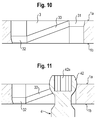
- the second holes 3 have a substantially oblong shape with the long side oriented in the direction of the longitudinal axis L.
- a hole 3 has an upper seat portion 31 which has the shape of a hollow spherical section matching the exterior spherical surface portion of the head 42.
- a lower seat portion 32 is provided at the opposite short side of the oblong hole 3 adjacent the bottom side 1b.
- the shape of the seat portion 32 is also spherical and matches the shape of the exterior surface portion of the head 42.
- an inclined spherical groove 33 extends along the inner wall of the long side of the oblong hole, the size of which is adapted to the exterior surface portion of the head 42 so that the head 42 can be guided along the groove 33.
- the elements of the bone plate assembly are made of a body compatible material, such as a body compatible metal, for example stainless steel or titanium or a body compatible metal alloy such as Ni-Ti alloys, for example Nitinol, or of a body compatible plastic material, for example medical grade PEEK or of combinations thereof.
- a body compatible material such as a body compatible metal, for example stainless steel or titanium or a body compatible metal alloy such as Ni-Ti alloys, for example Nitinol, or of a body compatible plastic material, for example medical grade PEEK or of combinations thereof.
- the plate member, the locking elements and the bone anchors can be made of different materials.
- the number of bone screws necessary for the stabilization of the bone parts or bone fragments is determined. It should be noted that in some cases it is not necessary to use all the holes provided on the plate member. Holes which are not used for bone screws may be closed by a plug member to be described below. Once, the necessary number and types of the screws are determined, the screws are inserted into the first holes 2 and/or second holes 3. After positioning the plate member at the fracture site the screws are inserted into the bone parts at the desired angle. The bone screws are inserted into the holes at this desired angle and the spherical seat allows placement of the head of the screw in the hole at this angle.
- the head 42 of each bone screw After full insertion of bone screws the head 42 of each bone screw, which is inserted into a first hole 2, abuts against the seat portion 21 of the hole 2. Already in this condition the angle between the bone screw and the plate member is fixed when at least two bone screws are inserted.
- the locking element 5 can be used which is inserted into the bore and tightened so that it locks the head in the selected angular position. If desired, different locking elements can be applied to different screws in order to provide for full locking, frictional locking or free angulation with the locking member only preventing pull-out of the screw as described above.
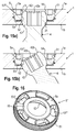
- the holes 3 are used for providing a self-compression effect.
- the bone screws 4 which are inserted into the oblong holes 3 are oriented substantially vertically relative to the plate member.
- the screw head 42 which is first seated in the upper seat portion 31 slides downwards along the inclined groove 33 until it rests in the lower seat portion 32.
- the second holes are arranged such that the lower seat portion 32 faces the center of the plate member. Since the screw head 42 is fixedly connected to the threaded shank 41 which is screwed into the bone the movement of the head 42 along the groove 33 leads to a movement of the bone part or fragment relative the plate and as a result to a compression of the bone parts against each other and against the plate member.
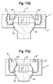
- FIG. 12 the plate member 1' has a contoured shape.
- the outer contour in a top view is slightly trapezoidal with rounded corners and a broadened middle portion.
- spherically shaped recesses 7 are provided at the lower side 1b to reduce the contact area with the bone. A minimal contact area of the plate member with the bone surface may be required in certain cases to prevent injury of the bone surface and compression of blood vessels etc.
- the recesses 7 also result in plate member portions with different thickness.
- the plate can be bent in portions with a smaller thickness the bone plate assembly can be used as a dynamic compression plate.
- two holes are provided at the short sides 1c and three holes are provided in the center of the plate in a longitudinal direction.
- the holes 2 may be offset from the longitudinal axis. The number is not limited to the number shown but can vary. Between the holes 2 near the short sides 1c and the holes 2 in the center second holes 3 may be provided for self-compression.
- the first holes 2 in the center section of the plate member are not used for screws. They may be closed by a plug member 8 shown in Fig. 14 .
- the plug member 8 is substantially cylindrical with a top side 8a and a bottom side 8b. It has a first portion 81 which has a threaded portion 82 cooperating with the threaded portion 23 of the bore 22. The first portion 81 fits into the bore 22 so that the top surface 8a is substantially flush with the top surface 1 a of the plate member 12'.
- a recess 53 which has an approximate star-shape is provided in the top surface 8a of the plug member as for the locking element 5.
- the plug member can prevent cracking or breaking of a plate member at the thinned portions 7.
- the plug member 8 Adjacent the cylindrical portion 81 the plug member 8 has a spherically shaped projection 83 which fits into the seat portion 21 of the hole 2 so that after insertion of the plug member 8 the hole 2 is closed.
- the bottom side 8d may be flush with the bottom side 1b of the plate member.
- a locking element as described above can be used as a plug member.
- the bone plate assembly includes a modified locking element as shown in Figs. 15a ), 15b).
- the locking element 5' differs from the locking element of the previous embodiments by the shape of the recess 53'" at the top side 5a of the locking element which serves for the driver.
- a coaxial through-hole 54 is provided. All other features of the locking element are the same or can be present in the same manner as for the locking element of the previous embodiments.
- the coaxial through-hole 54 extends from the top side 5a through the locking element and continuous in the recess 52.
- the diameter of the coaxial through-hole is configured. Hence, the diameter of the through-hole can be larger than the diameter of the free end 42b of the screw head 42.
- the coaxial through hole 54 allows to further reduce the thickness of the plate member and the locking element, since the head of the screw can partially extend into the hole when the screw is in an angled position as shown in Fig. 15b )
- the recess for the driver which is used to tighten the locking element 5' is in this embodiment composed of a plurality of spaced apart recesses forming elongate pockets 53"' which are arranged around the central axis of the locking element in a circumferential manner.
- the depth of the pockets 53'" is configured such that the pockets extend below the free end 42b of the screw head when the screw head 42 rests in the seat 21.
- the distance b of the deepest portion of the pockets 53" from the top side 1a is larger than the deepest portion of the recess 52 from the top side 1a in the previous embodiments. Since the recess 53" extends into the body of the locking element in an area around the screw head the locking element has a small thickness. Therefore, a low profile polyaxial locking plate is provided. In a modified embodiment the recess may extend completely through the locking element.
- the locking element 5" has an annular rim 55 on the top side 5a.
- FIGs. 17a) to 17e schematic sectional views of a portion of the bone plate assembly with a polyaxial bone screw and a locking element are shown that explain a dimensional relationship of the recess for the driver and the head of the bone screw.
- a locking element is shown wherein the recess 52 for the head extends into the top side 5a so that a through-hole 54 is formed.
- a first level L1 is defined by the highest point of a circle that is drawn around the screw head with a diameter that corresponds to the largest diameter d of the screw head.
- the largest diameter d of the screw head 42 is located above the opening 20 on the bottom side of the bone plate.
- the bottom of the recess 53"' for the driver defines a second level L2.
- the level L2 is below L1. With this relationship the bone plate assembly has a low profile. Simultaneously, a large range of angulation of the screw can be achieved.
- the locking element is similar to the locking element shown in Fig. 16 and has an annular rim 55 at the top side. Also in this case, the highest point of a circle which is projected from the position of the greatest diameter d of the screw head defines a level L1 and the bottom of the recess 53"' defines a level L2 which is below L1.
- Fig. 17c shows a locking element that has the highest point of a circle projected from the position with the largest diameter d of the screw head 42 on a level L1 which is on the same level L2 as the bottom of the recess 53"' for the driver. A low profile can still be obtained.
- Fig. 17d the top surface 5a of the locking element is closed.
- the highest point of the circle is above the closed top surface.
- the level L2 is below L1.
- Fig. 17e shows a locking element which has a conically-shaped first recess 52' which contacts the head 42 of the polyaxial bone screw 4. Also in this case the level L2 is the same as the level L1 or below L1.
- the contact area between the screw head 42 and the recess 52 is not limited to a spherical surface, it can be a line contact or can have another shape.
- the recess 52 for the screw head is not limited to a spherical or a conical form but can have various shapes.
- the screw head needs not to be completely spherical. It is sufficient that it has a spherically shaped surface portion. It can also be shaped otherwise, as long as it can pivot in the seat.
- Figs. 18 to 20 show a tool for use with locking element and the bone plate assembly.
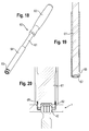
- the tool 60 comprises a driver 61 with an engagement portion 62 for engaging the locking element and a handle 63.
- the engagement portion 62 of the driver 61 is configured to engage the engagement structure such as the pockets 53'" in the locking element 5' of Figs. 15 and 16 or the groove 53 in the locking element 5 of Figs. 1 to 9 .
- the driver 61 extends with its engagement portion 62 through a tubular holder 64 and is axially movable and rotatable therein.
- the holder 64 has at a distance from its free end which faces away from the handle 63 a radial slot 65 which is configured to pass the locking element 5 therethrough.
- the counter holder 64 has at its free end a portion with an internal thread 66 cooperating with the external thread 51 of the locking element 5.
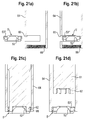
- Figs. 21a) to 21d The steps of taking up the locking element with the tool 60 are schematically shown in Figs. 21a) to 21d ). Exemplary the locking element of Fig. 15 and 16 is shown.
- the driver 61 is retracted and the holder 64 is free at the location of the slot 65.
- the locking element 5' is introduced through the slot 65 into the holder 64.
- the bottom side 5b of the locking element which has the recess 52 for the head, faces the threaded portion 66 of the holder 64. Then, as shown in Fig.
- the driver 61 is moved through the holder 64 to engage the pockets 53'" and the locking element 5' is screwed into the threaded portion 66 of the holder 64. Then, as shown in Fig. 21d ), the driver 61 can be retracted and the locking element can be placed into the hole 2. Finally, as shown in Fig. 20 before, the driver 61 can be advanced again and engage the pockets 53"' of the locking element to screw the locking element further into the hole 2. If desired, the locking element is tightened to press onto the head to fix the angular position of the bone screw.
- the locking element can be safely taken up and held in the holder. In addition, it can be safely placed into the hole and inserted therein.
- the locking element may be configured to be used with a polyaxial bone anchor, and be substantially cylindrical with a bottom side (5b) facing a head (42) of the bone anchor, a top side (5a) opposite to the bottom side (5b), and a surface portion with an external thread.
- the locking element may have a first recess (52, 52') at the bottom side for accommodating at least a portion of the head (42), and a second recess (53, 53', 53"') at the top side (5a) for engagement with a driver, the second recess being located outside the center of the top side (5a).
- the head (42) may have a portion with a largest diameter (d), and a first level L1 defined by the highest point of a circle with the largest diameter drawn around the head, and a second level L2 is defined by the bottom of the second recess (53, 53', 53"'), L2 being at a level not higher than L1.
- the locking element may include a coaxial through-hole (54).
- a contact area of the first recess (52) that contacts the head may be a conically shaped contact, a line contact, and/or a spherically-shaped contact.
- the second recess (53, 53", 53") may be located substantially in a radially outer area of the top side (5a).
- the second recess (53, 53') may include a ring-shaped groove with a contour configured have form-fitting engagement with the driver.
- the contour may be selected from at least one of the group consisting of a star-like contour, a polygonal contour, and a flower-like contour.
- the second recess may include a plurality of pockets (53"').
- the pockets may be configured to extend through the locking element into the bottom side (5b).
- a distance (a) of a deepest portion of the second recess (52), measured from the top side (5a) is smaller than a depth (b) of the first recess (53, 53', 53") measured from the top side (1a).
- the locking element may also include a portion (51) with an external thread.
- the locking element (5) may include a portion with the external thread that spans the entire locking element (5), making the locking element (5) fully threaded, and/or a portion with the external thread that does not span the entire locking element (5), having a non-threaded section (51a) adjacent the bottom side (5b).
- An axial length of the non-threaded section (51a) may be substantially equal to or smaller than the axial length of a threaded section of the portion with the external thread (51).
- a bone plate assembly may include an elongate plate member (1, 1') with a top side (1a) and a bottom side (1b), at least two holes (2, 2, 3) extending from the top side to the bottom side, and at least two bone anchors (4), each bone anchor comprising a shank (41) configured to anchor into the bone, and a head (42) having a portion with a largest outer diameter (d), wherein the shank is extendable through the hole.
- At least one of the holes (2) may be configured to define a seat (21) at the bottom side (1b) adapted to pivotably receive the head (42), wherein the at least one of the holes (2) includes a bore (22) at the top side (1a) with a bore axis and an inner diameter (D) at least as large as the largest diameter (d) of the head (42).
- the locking element (5, 5', 5", 5"') may be configured to be inserted into the bore (22), having a central axis coaxial with the bore axis, a bottom side (5b) facing the head, and a top side (5a) facing away from the head.
- the locking element may have a first recess (52, 52') at the bottom side for at least partially covering the head, and a second recess (53, 53', 53"') at the top side (5a) for engagement with a driver, the second recess being located outside the center of the top side (5a).
- the highest point of a circle with the largest diameter (d) that is drawn around the head may define a first level L1 and the bottom of the second recess (53, 53', 53"') may define a second level L2, which is at a level not higher than L1.
- the bone plate assembly may include a plurality of locking elements and these may be configured to lock the head and/or prevent loosening of the bone anchoring element and/or bone plate assembly, while allowing pivotal movement.
- a bone plate assembly may include an elongate plate member (1, 1') with a top side (1a) and a bottom side (1b), at least two holes (2, 2, 3) extending from the top side to the bottom side, and at least two bone anchors (4), each bone anchor comprising a shank (41) configured to anchor into the bone, and a head (42) having a top (42a) and a portion with a largest outer diameter (d), wherein the shank is extendable through the hole.
- At least one of the holes (2) may be configured to define a seat (21) at the bottom side (1b) adapted to pivotably receive the head, (42) wherein the at least one of the holes includes a bore (22) at the top side (1a) with a bore axis and an inner diameter (D) which is at least as large as the largest diameter (d) of the head (42).
- the head may be pivotably received when a bone anchor is inserted into the bone plate assembly, for example. However, at such times as, for example, upon insertion of the bone anchor into bone, pivoting may be restricted.
- a locking element (5, 5') is configured to be inserted into the bore and having a central axis coaxial with the bore axis, a bottom side (5b) facing the head, a top side (5a) facing away from the head and a recess (53, 53', 53"') at the top side (5a) configured to be engaged with a driver, the recess being located outside the center of the top side (5a) and having a depth that extends below the top (42a) of the screw head (42) when the screw head (42) is in the seat (21).
- the bore may have a portion (23) with an internal thread and the locking element (5) may have a portion (51) with an external thread adapted to cooperate with the internal thread of the bore. At least one of the internal thread and the external thread may include a two-start thread. Furthermore, another locking element may be included in the bone plate assembly, and the locking element and the another locking element may have different axial lengths.
- the first recess (52) may include a spherical shape and a depth measured from the bottom side (5b) substantially equal to or slightly larger than half of the diameter (d) of the head..
- the bone plate assembly may also include a plug member (8) adapted to close a hole if a bone anchor is not used.
- a tool adapted for use with a bone plate assembly described herein may include a driver (61) with an engagement portion (62) configured to engage a locking element; and a tubular holder (64).
- the driver may be configured to extend with the engagement portion (62) through the tubular holder (64), and may be axially movable and rotatable within the holder.
- the holder may have a radial slot (65) adapted for insertion of the locking element.
- the holder may include a portion with an internal thread (66) for cooperation with an external thread (51) of the locking element.
- the shape of the plate member is not restricted to the embodiments shown. Other shapes are also conceivable.
- the bone anchor is not limited to a bone screw which has a threaded shank. Smooth, barbed or roughened pins are also conceivable. Further, any known bone screws may be used. Additionally, other bone anchors may be used.
Landscapes
- Health & Medical Sciences (AREA)
- Orthopedic Medicine & Surgery (AREA)
- Surgery (AREA)
- Life Sciences & Earth Sciences (AREA)
- Heart & Thoracic Surgery (AREA)
- Nuclear Medicine, Radiotherapy & Molecular Imaging (AREA)
- Engineering & Computer Science (AREA)
- Biomedical Technology (AREA)
- Medical Informatics (AREA)
- Molecular Biology (AREA)
- Animal Behavior & Ethology (AREA)
- General Health & Medical Sciences (AREA)
- Public Health (AREA)
- Veterinary Medicine (AREA)
- Neurology (AREA)
- Surgical Instruments (AREA)
Description
- The invention relates to a locking element for a polyaxial bone anchor and to a bone plate assembly for the immobilization of bones or bone fragments or vertebrae and a tool used therefor. Particularly, the invention relates to a bone plate assembly with a polyaxial coupling between the bone anchors of the bone plate assembly and a plate with an increased range of angular motion and low profile.
-
US 6,022,350 describes a bone fixing device comprising an elongate single-piece plate-shaped element receiving at least one bone-fastening screw which passes through an orifice formed in the plate-shaped element. The head of the screw includes an essentially spherical surface for bearing against a bearing surface of essentially circular cross-section in the bottom of the plate element. The device further includes a plug for coming into clamping contact against said screw head to hold it in a desired angular position. The outside face of the plug includes a central tightening socket which is identical to that in the screw head so that the same tightening tool can be used. -
US 5,531,746 describes a polyaxial screw plate assembly for immobilization of vertebral bones including an elongate plate having a plurality of holes wherein the bottom portion of the holes has a curved interior surface which forms an annular lip for supporting a semi-spherical head portion of a bone screw. A coupling element in the form of a short threaded cylindrical piece having a concave bottom locks the screw into the hole. - In addition, various bone plate assemblies are known which use bushings with a spherical exterior surface which can pivot in holes with a spherical interior surface and which encompass a screw head to provide polyaxial angular adjustability of bone screws relative to the plate. Examples of such assemblies are known, for example, from
WO 99/05968 WO 00/04836 -
EP 0 988 833 A2 relates to a plate for osteosynthesis with several bone screws. The bone screws have a spherical head that can lie on a ring-shaped, substantially spherical surface of the plate in different angular positions. The plate further comprises securing screws that press in their axial direction onto the spherical head. The securing screw comprises recesses for transferring torque with a tool. The recesses are open to the circumference of the securing screw. -
US5904683 A discloses a locking element according to the preamble ofclaim 1. - While the known bone plate assemblies can provide polyaxial adjustment of the bone anchors relative to the plate, there is still a need for an improved bone plate assembly which allows for a greater range of angular positions, a lower profile of the plate-screw construct and a variety of usage.
- It is therefore the object of the invention to provide a low profile bone plate assembly and a locking element for a polyaxial bone anchor and a tool therefor which allows a polyaxial adjustment of the bone anchor and the plate with a wide range of angular motion with a simple design while simultaneously providing a high safety of use.
- The object is solved by a locking element and a bone plate assembly according to the claims of the present invention.
- The bone plate assembly according to the invention allows a pivot angle of the bone anchor relative to the plate of up to around 35° with respect to the vertical position. This corresponds to a motion cone of up at least 60°. The position of the bone anchor relative to the plate has an angular stability due to the locking element. The locking can be carried out by application of low torque. With the locking element, the screws are secured against pull-out. Different locking elements can be provided to achieve either full locking or frictional locking or to allow free angulation while only preventing pull-out of the anchor.
- In addition, the bone plate assembly is designed with a minimum of necessary parts and has a low profile. Due to the simple design and the small number of parts which are setting up the bone plate assembly, it is economical to manufacture.
- The holes for the bone anchors in the plate member are designed such that bone anchors with or without a locking member can be used. Additionally, locking plugs can be provided to close a hole without the use of a bone anchor, for example, if there are small bone fragments or for ensuring stability against cracking.
- Furthermore, the plate member may have offset holes which are offset from a central longitudinal line for more variety of usage. The plate member can be designed to have a minimal bone contact area and can be used as a dynamic plate. Also, the plate member may be contoured to provide a specific shape for specific clinical applications.
The bone plate assembly is suitable for various clinical applications. For example, due to the low profile design, the bone plate assembly is suitable for the application in areas with minimal soft tissue coverage like the cervical spine or other small bones like the clavicle or the pelvis. - Further features and advantages of the invention will become apparent from the description of embodiments with reference to the accompanying drawings. In the drawings:
- Fig. 1
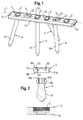
- shows a perspective view of a bone plate assembly according to a first embodiment.
- Fig. 2
- shows a schematic exploded sectional view of the portion of the bone plate of
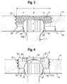
Fig. 1 including a hole, a bone screw and a locking element. - Fig. 3
- shows a schematic sectional view of a portion of the bone plate of
Fig. 1 including a hole and an inserted bone screw. - Fig. 4
- shows a schematic sectional view of a portion of the bone plate of
Fig. 1 with an inserted bone screw and a locking element. - Fig. 5
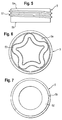
- shows a side view of the locking element of
Fig. 4 . - Fig. 6
- shows a top view of the locking element of
Fig. 4 . - Fig. 7
- shows a bottom view of the locking element of
Fig. 4 . - Fig. 8
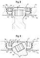
- shows a schematic sectional view of a portion of the bone plate of
Fig. 1 with an inserted bone screw in a vertical position and a slightly modified locking element. - Fig. 9
- shows the arrangement of
Fig. 8 with the bone screw in a pivoted position. - Fig. 10
- shows a schematic sectional view of a portion of the bone plate of
Fig. 1 including a second type of hole. - Fig. 11
- shows a schematic sectional view of a portion of the bone plate of
Fig. 1 including the second type of hole with an inserted bone screw. - Fig. 12
- shows a perspective view from the top of a second embodiment of the bone plate assembly.
- Fig. 13
- shows a perspective view from the bottom of the bone plate assembly of
Fig. 12 . - Fig. 14
- shows an enlarged schematic sectional view of a hole of the bone plate according to
Fig. 12 sealed by a plug member. - Fig. 15a)
- shows a schematic sectional view of a further embodiment of the bone plate assembly including the hole, the bone screw and a modified locking element, wherein the bone screw is in a straight position.
- Fig. 15b)
- shows the bone plate assembly of
Fig. 15a ) with the bone screw in an angled position. - Fig. 16
- shows an enlarged perspective view of the locking element of the embodiment according to
Figs. 15a) and 15b ). - Figs. 17a) to 17e)
- show a schematic sectional view of a portion of the bone plate with a polyaxial bone screw and a locking element, respectively, to illustrate a dimensional relationship between the recess for the driver and the head of the bone screw.
- Fig. 18
- shows a perspective view of a tool for inserting the locking element.
- Fig. 19
- shows an enlarged schematic sectional view of a portion of the tool of
Fig. 18 . - Fig. 20
- shows a further enlarged schematic sectional view of a portion of the bone plate with a polyaxial bone screw, the locking element and the tool.
- Figs. 21a) to 21d)
- show steps of using the tool.
- A first embodiment of the bone plate assembly will now be described with reference to
Figs. 1 to 9 . As can be seen in particular inFigs. 1 and 2 the bone plate assembly includes aplate member 1 which is in this embodiment a substantially rectangular body with a top side la, abottom side 1b,short sides 1c andlong sides 1d and a longitudinal axis L. A plurality offirst holes 2 extend through the plate member from the top side la to thebottom side 1b.Second holes 3 can be provided which are, for example, arranged between thefirst holes 2 also extend from thetop side 1a to thebottom side 1b. However, the number and arrangement of first and second holes can vary according to the size and shape of theplate member 1. The plate member may have onlyfirst holes 2 and thesecond holes 3 can be omitted. - The bone plate assembly further comprises a plurality of bone anchors in form of bones screws 4 which can be inserted into the
first holes 2 and/or thesecond holes 3. Thebone screw 4 has a threadedshank 41 with a tip and ahead 42. Thehead 42 has a spherical exterior surface portion and arecess 42a at itsfree end 42b opposite to theshank 41 for engagement with a screw driver. Other longitudinal bone anchors like pins, barbed or roughened nails can also be used. - As can be seen in
Figs. 1 and 2 alocking element 5 is provided for locking thebone screw 4 in thefirst holes 2 as described below. - The structure of the
first holes 2 will now be described with reference to afirst hole 2 shown inFigs. 3 and 4 . Thefirst hole 2 comprises anopening 20 at thebottom side 1b the inner diameter of which is larger than the outer diameter of the threadedshank 41 of the bone screw so that the threadedshank 41 can pass therethrough. The diameter is, however, smaller than the largest outer diameter d of thehead 42 so that thehead 42 cannot pass therethrough. Adjacent the opening 20 ahollow seat portion 21 is provided which forms a socket for a pivoting movement of thehead 42. This allows insertion of the bone screw at any desired angle. In the embodiment shown, theseat portion 21 is spherically-shaped with a radius that matches the radius of the spherically-shaped portion of thehead 42. When the head rests in the seat portion, a part of the spherical section of the head projects out of thebottom side 1b. The height h of theseat portion 21 is smaller than the radius of thehead 42 and preferably smaller than half of, more preferably smaller than or equal to a quarter of the radius of thehead 42. Between theseat portion 21 and thetop side 1a acylindrical bore 22 with aportion 23 having an internal thread is provided. As shown inFig. 3 , in one exemplary aspect of the invention, this internal thread is a full thread, reaching to the top of thecylindrical bore 22. The inner diameter of thebore 22 is larger than the inner diameter of theseat portion 21 and larger than the outer diameter of the spherical portion of thehead 42. In other words, the inner diameter D of thebore 22 is larger than the outer diameter d of thehead 42. By means of this, access to thehead 42 with a screw driver is possible even at large pivot angles. For example, the inner diameter D of thebore 22 may, in one exemplary aspect of the invention, be approximately 1.2 to 1.7 times larger than the maximum outer diameter d of thehead 42. However, this exemplary aspect is for illustration only and is not a limitation on the scope of the invention. The threadedportion 23 can have any thread form, for example a metric thread. Thethickness 1 of theplate member 1 at the hole, that means the distance of thetop side 1a from thebottom side 1b is smaller or equal to the largest outer diameter d of thehead 42. - The
opening 20 widens in aconical portion 24 towards thebottom side 1b to allow even larger pivot angles of thebone screw 4. - The locking element will now be described with reference to
Figs. 1, 2 and4 to 7 . The lockingelement 5 is substantially cylindrical and has atop side 5a and abottom side 5b and a threadedexterior surface portion 51 which cooperates with the internally threadedportion 23 of thebore 22 of the plate member. The height of the locking element corresponds substantially to the depth of thebore 22 so that when the lockingelement 5 is screwed into thebore 22 itstop side 5a is substantially flush with thetop side 1a of the plate member. - As can be seen in particular in
Fig. 4 , the locking element is partially threaded. Thenon-threaded portion 51a has an axial length which may be about equal to or smaller than that of the threadedportion 51. The locking element can also be fully threaded. - On the
bottom side 5b thelocking element 5 comprises preferably a spherically-shapedrecess 52 which fits to the spherically-shaped portion of thehead 42. The depth of therecess 52 can be equal to or larger than the radius of the spherical portion of thehead 42. By means of this, the pressure exerted by the lockingelement 5 onto thehead 42 is smoothly distributed onto thehead 42. - A
recess 53 in form of a ring-shaped groove with a contour which allows a form-fit engagement of a corresponding tool which is provided in the outer radial area is provided in thetop side 5a of thelocking element 5. As shown inFig. 6 , the contour of the groove in this embodiment has a star-like shape. The central area of thetop side 5a is solid, i.e. is without a recess. - As can be seen in particular in
Fig. 4 , the depth of b of therecess 53 is larger than the distance a of the deepest portion of therecess 52 from thetop side 5a. Since therecess 53, which serves for engagement with a driver, is in the outer area of thetop side 5a, thespherical recess 53 extending from thebottom side 5b can have a large depth which results in an increased contact area between the lockingelement 5 and thehead 42. On the other hand, theseat portion 21 can be kept small to allow large angulation of thebone screw 4. - Furthermore, with the design described above the locking element has a reduced height. As a consequence thereof, the overall height of the bone plate assembly can be kept small.
- It is possible to provide different locking elements which differ in their axial length or a different depth in the spherically-shaped recess to achieve either full locking of the head or a frictional locking. Frictional locking allows pivoting under application of an additional force which exceeds the frictional force between head and plate member. A further different locking element may have a length or a different depth in the spherically-shaped recess which allows a free pivotal movement of the screw with the locking element only preventing pull-out of the screw.
- The overall height of the bone plate assembly can be further downsized by using a two-start thread for the threaded portions.
- The design of the
holes 2 and thelocking element 5 are not restricted to the specific embodiment shown. For example, theseat portion 21 needs not to be spherically-shaped, but can have another shape such as a taper or even can be realized only by the edge of theopening 20. Between theseat portion 21 and thebore 22 transitional sections of the hole can be arranged provided they do not restrict the pivoting motion of the screw head. Thebore 22 is shown to be cylindrically-shaped. However, it could also be a conical bore. The locking element would then be adapted thereto. Since only a relatively small clamping force is necessary to lock the angular position of the bone screw, other kinds of connections between the locking element and the bore can be used, for example, a bayonet locking structure. Also, the orientation of the holes in vertical direction needs not to be perpendicular to the surface but can include an angle with the normal onto the surface of the plate member for providing an initial angulation. - In
Fig. 8 and 9 , the lockingelement 5 is slightly modified in such a way that therecess 53 is closer to the outer edge than in thelocking element 5 shown inFig. 4 . The recess 52' is deeper than therecess 52 of the locking element ofFig. 4 and has a flat portion near thetop side 5a. The profile of the assembly can be further downsized by this design. - The
recess 53 forms a drive portion for a tool such as a screw driver. It is not restricted to the shown star-like contour but can also have other shapes such as, for example, a polygon, a wavy or a flower-like contour or can have interruptions so that only groove portions or recesses are provided. - With the design described above a large pivot angle such that a range of motion of at least 60° up to 70° can be achieved.
- Next, the
second holes 3 are described with reference toFigs. 1 ,8 and 9 . Thesecond holes 3 have a substantially oblong shape with the long side oriented in the direction of the longitudinal axis L. As can be seen in particular inFig. 8 , ahole 3 has anupper seat portion 31 which has the shape of a hollow spherical section matching the exterior spherical surface portion of thehead 42. Further, alower seat portion 32 is provided at the opposite short side of theoblong hole 3 adjacent thebottom side 1b. The shape of theseat portion 32 is also spherical and matches the shape of the exterior surface portion of thehead 42. Between theupper seat portion 31 and thelower seat portion 32 an inclinedspherical groove 33 extends along the inner wall of the long side of the oblong hole, the size of which is adapted to the exterior surface portion of thehead 42 so that thehead 42 can be guided along thegroove 33. - The elements of the bone plate assembly are made of a body compatible material, such as a body compatible metal, for example stainless steel or titanium or a body compatible metal alloy such as Ni-Ti alloys, for example Nitinol, or of a body compatible plastic material, for example medical grade PEEK or of combinations thereof. For example, the plate member, the locking elements and the bone anchors can be made of different materials.
- Now, use of the bone plate assembly according to the first embodiment will be described. First, the number of bone screws necessary for the stabilization of the bone parts or bone fragments is determined. It should be noted that in some cases it is not necessary to use all the holes provided on the plate member. Holes which are not used for bone screws may be closed by a plug member to be described below. Once, the necessary number and types of the screws are determined, the screws are inserted into the
first holes 2 and/orsecond holes 3. After positioning the plate member at the fracture site the screws are inserted into the bone parts at the desired angle. The bone screws are inserted into the holes at this desired angle and the spherical seat allows placement of the head of the screw in the hole at this angle. After full insertion of bone screws thehead 42 of each bone screw, which is inserted into afirst hole 2, abuts against theseat portion 21 of thehole 2. Already in this condition the angle between the bone screw and the plate member is fixed when at least two bone screws are inserted. To further stabilize the connection between the bone screw and the plate the lockingelement 5 can be used which is inserted into the bore and tightened so that it locks the head in the selected angular position. If desired, different locking elements can be applied to different screws in order to provide for full locking, frictional locking or free angulation with the locking member only preventing pull-out of the screw as described above. - The
holes 3 are used for providing a self-compression effect. The bone screws 4 which are inserted into theoblong holes 3 are oriented substantially vertically relative to the plate member. Thescrew head 42 which is first seated in theupper seat portion 31 slides downwards along theinclined groove 33 until it rests in thelower seat portion 32. Preferably, the second holes are arranged such that thelower seat portion 32 faces the center of the plate member. Since thescrew head 42 is fixedly connected to the threadedshank 41 which is screwed into the bone the movement of thehead 42 along thegroove 33 leads to a movement of the bone part or fragment relative the plate and as a result to a compression of the bone parts against each other and against the plate member. - A second embodiment will be described with reference to
Figs. 12 to 14 . Parts which are the same as those of the previous embodiments are designated with the same reference numerals and the description thereof is not repeated. As can be seen inFig. 12 the plate member 1' has a contoured shape. The outer contour in a top view is slightly trapezoidal with rounded corners and a broadened middle portion. Further, spherically shapedrecesses 7 are provided at thelower side 1b to reduce the contact area with the bone. A minimal contact area of the plate member with the bone surface may be required in certain cases to prevent injury of the bone surface and compression of blood vessels etc. - The
recesses 7 also result in plate member portions with different thickness. The plate can be bent in portions with a smaller thickness the bone plate assembly can be used as a dynamic compression plate. - In this embodiment, two holes are provided at the
short sides 1c and three holes are provided in the center of the plate in a longitudinal direction. Theholes 2 may be offset from the longitudinal axis. The number is not limited to the number shown but can vary. Between theholes 2 near theshort sides 1c and theholes 2 in the centersecond holes 3 may be provided for self-compression. - In the case of small bone fragments which shall be immobilized by means of the bone plate assembly not all holes may be used for bone screws 4. As shown in
Figs. 12 and 13 , for example, thefirst holes 2 in the center section of the plate member are not used for screws. They may be closed by a plug member 8 shown inFig. 14 . The plug member 8 is substantially cylindrical with atop side 8a and abottom side 8b. It has afirst portion 81 which has a threadedportion 82 cooperating with the threadedportion 23 of thebore 22. Thefirst portion 81 fits into thebore 22 so that thetop surface 8a is substantially flush with thetop surface 1 a of the plate member 12'. Arecess 53 which has an approximate star-shape is provided in thetop surface 8a of the plug member as for thelocking element 5. The plug member can prevent cracking or breaking of a plate member at the thinnedportions 7. - Adjacent the
cylindrical portion 81 the plug member 8 has a spherically shapedprojection 83 which fits into theseat portion 21 of thehole 2 so that after insertion of the plug member 8 thehole 2 is closed. The bottom side 8d may be flush with thebottom side 1b of the plate member. - Alternatively, a locking element as described above can be used as a plug member.
- In a further embodiment, the bone plate assembly includes a modified locking element as shown in
Figs. 15a ), 15b). The locking element 5' differs from the locking element of the previous embodiments by the shape of the recess 53'" at thetop side 5a of the locking element which serves for the driver. Further a coaxial through-hole 54 is provided. All other features of the locking element are the same or can be present in the same manner as for the locking element of the previous embodiments. The coaxial through-hole 54 extends from thetop side 5a through the locking element and continuous in therecess 52. The diameter of the coaxial through-hole is configured. Hence, the diameter of the through-hole can be larger than the diameter of thefree end 42b of thescrew head 42. This enables thescrew head 42 to at least partly extend into the through-hole 54. The coaxial throughhole 54 allows to further reduce the thickness of the plate member and the locking element, since the head of the screw can partially extend into the hole when the screw is in an angled position as shown inFig. 15b ) - The recess for the driver which is used to tighten the locking element 5' is in this embodiment composed of a plurality of spaced apart recesses forming
elongate pockets 53"' which are arranged around the central axis of the locking element in a circumferential manner. - The depth of the pockets 53'" is configured such that the pockets extend below the
free end 42b of the screw head when thescrew head 42 rests in theseat 21. In other words, the distance b of the deepest portion of thepockets 53" from thetop side 1a is larger than the deepest portion of therecess 52 from thetop side 1a in the previous embodiments. Since therecess 53" extends into the body of the locking element in an area around the screw head the locking element has a small thickness. Therefore, a low profile polyaxial locking plate is provided. In a modified embodiment the recess may extend completely through the locking element. - In a further modification shown in
Fig. 16 , the lockingelement 5" has anannular rim 55 on thetop side 5a. - In
Figs. 17a) to 17e ) schematic sectional views of a portion of the bone plate assembly with a polyaxial bone screw and a locking element are shown that explain a dimensional relationship of the recess for the driver and the head of the bone screw. InFig. 17a ) a locking element is shown wherein therecess 52 for the head extends into thetop side 5a so that a through-hole 54 is formed. A first level L1 is defined by the highest point of a circle that is drawn around the screw head with a diameter that corresponds to the largest diameter d of the screw head. The largest diameter d of thescrew head 42 is located above theopening 20 on the bottom side of the bone plate. The bottom of therecess 53"' for the driver defines a second level L2. As shown inFig. 17a ), the level L2 is below L1. With this relationship the bone plate assembly has a low profile. Simultaneously, a large range of angulation of the screw can be achieved. - In
Fig. 17b ) the locking element is similar to the locking element shown inFig. 16 and has anannular rim 55 at the top side. Also in this case, the highest point of a circle which is projected from the position of the greatest diameter d of the screw head defines a level L1 and the bottom of therecess 53"' defines a level L2 which is below L1. -
Fig. 17c ) shows a locking element that has the highest point of a circle projected from the position with the largest diameter d of thescrew head 42 on a level L1 which is on the same level L2 as the bottom of therecess 53"' for the driver. A low profile can still be obtained. - In
Fig. 17d ) thetop surface 5a of the locking element is closed. The highest point of the circle is above the closed top surface. Also in this case the level L2 is below L1. -
Fig. 17e ) shows a locking element which has a conically-shaped first recess 52' which contacts thehead 42 of thepolyaxial bone screw 4. Also in this case the level L2 is the same as the level L1 or below L1. - The contact area between the
screw head 42 and therecess 52 is not limited to a spherical surface, it can be a line contact or can have another shape. Thus, therecess 52 for the screw head is not limited to a spherical or a conical form but can have various shapes. - The screw head needs not to be completely spherical. It is sufficient that it has a spherically shaped surface portion. It can also be shaped otherwise, as long as it can pivot in the seat.
-
Figs. 18 to 20 show a tool for use with locking element and the bone plate assembly. Thetool 60 comprises adriver 61 with anengagement portion 62 for engaging the locking element and ahandle 63. Theengagement portion 62 of thedriver 61 is configured to engage the engagement structure such as the pockets 53'" in the locking element 5' ofFigs. 15 and 16 or thegroove 53 in thelocking element 5 ofFigs. 1 to 9 . Thedriver 61 extends with itsengagement portion 62 through atubular holder 64 and is axially movable and rotatable therein. Theholder 64 has at a distance from its free end which faces away from the handle 63 aradial slot 65 which is configured to pass the lockingelement 5 therethrough. Further, thecounter holder 64 has at its free end a portion with aninternal thread 66 cooperating with theexternal thread 51 of thelocking element 5. - The steps of taking up the locking element with the
tool 60 are schematically shown inFigs. 21a) to 21d ). Exemplary the locking element ofFig. 15 and 16 is shown. In a first step, thedriver 61 is retracted and theholder 64 is free at the location of theslot 65. In a next step as shown inFig. 21b ) the locking element 5' is introduced through theslot 65 into theholder 64. Thebottom side 5b of the locking element, which has therecess 52 for the head, faces the threadedportion 66 of theholder 64. Then, as shown inFig. 21c ), thedriver 61 is moved through theholder 64 to engage the pockets 53'" and the locking element 5' is screwed into the threadedportion 66 of theholder 64. Then, as shown inFig. 21d ), thedriver 61 can be retracted and the locking element can be placed into thehole 2. Finally, as shown inFig. 20 before, thedriver 61 can be advanced again and engage thepockets 53"' of the locking element to screw the locking element further into thehole 2. If desired, the locking element is tightened to press onto the head to fix the angular position of the bone screw. - With the tool, the locking element can be safely taken up and held in the holder. In addition, it can be safely placed into the hole and inserted therein.
- Referring again to the locking element, it may be configured to be used with a polyaxial bone anchor, and be substantially cylindrical with a bottom side (5b) facing a head (42) of the bone anchor, a top side (5a) opposite to the bottom side (5b), and a surface portion with an external thread. The locking element may have a first recess (52, 52') at the bottom side for accommodating at least a portion of the head (42), and a second recess (53, 53', 53"') at the top side (5a) for engagement with a driver, the second recess being located outside the center of the top side (5a). The head (42) may have a portion with a largest diameter (d), and a first level L1 defined by the highest point of a circle with the largest diameter drawn around the head, and a second level L2 is defined by the bottom of the second recess (53, 53', 53"'), L2 being at a level not higher than L1.
- The locking element may include a coaxial through-hole (54). A contact area of the first recess (52) that contacts the head may be a conically shaped contact, a line contact, and/or a spherically-shaped contact. The second recess (53, 53", 53") may be located substantially in a radially outer area of the top side (5a). The second recess (53, 53') may include a ring-shaped groove with a contour configured have form-fitting engagement with the driver. The contour may be selected from at least one of the group consisting of a star-like contour, a polygonal contour, and a flower-like contour. The second recess may include a plurality of pockets (53"'). The pockets may be configured to extend through the locking element into the bottom side (5b). A distance (a) of a deepest portion of the second recess (52), measured from the top side (5a) is smaller than a depth (b) of the first recess (53, 53', 53") measured from the top side (1a). The locking element may also include a portion (51) with an external thread. The locking element (5) may include a portion with the external thread that spans the entire locking element (5), making the locking element (5) fully threaded, and/or a portion with the external thread that does not span the entire locking element (5), having a non-threaded section (51a) adjacent the bottom side (5b). An axial length of the non-threaded section (51a) may be substantially equal to or smaller than the axial length of a threaded section of the portion with the external thread (51).
- Referring again to a bone plate assembly, it may include an elongate plate member (1, 1') with a top side (1a) and a bottom side (1b), at least two holes (2, 2, 3) extending from the top side to the bottom side, and at least two bone anchors (4), each bone anchor comprising a shank (41) configured to anchor into the bone, and a head (42) having a portion with a largest outer diameter (d), wherein the shank is extendable through the hole. At least one of the holes (2) may be configured to define a seat (21) at the bottom side (1b) adapted to pivotably receive the head (42), wherein the at least one of the holes (2) includes a bore (22) at the top side (1a) with a bore axis and an inner diameter (D) at least as large as the largest diameter (d) of the head (42). The locking element (5, 5', 5", 5"') may be configured to be inserted into the bore (22), having a central axis coaxial with the bore axis, a bottom side (5b) facing the head, and a top side (5a) facing away from the head. The locking element may have a first recess (52, 52') at the bottom side for at least partially covering the head, and a second recess (53, 53', 53"') at the top side (5a) for engagement with a driver, the second recess being located outside the center of the top side (5a). The highest point of a circle with the largest diameter (d) that is drawn around the head may define a first level L1 and the bottom of the second recess (53, 53', 53"') may define a second level L2, which is at a level not higher than L1.
- The bone plate assembly may include a plurality of locking elements and these may be configured to lock the head and/or prevent loosening of the bone anchoring element and/or bone plate assembly, while allowing pivotal movement.
- Referring once again to a bone plate assembly, it may include an elongate plate member (1, 1') with a top side (1a) and a bottom side (1b), at least two holes (2, 2, 3) extending from the top side to the bottom side, and at least two bone anchors (4), each bone anchor comprising a shank (41) configured to anchor into the bone, and a head (42) having a top (42a) and a portion with a largest outer diameter (d), wherein the shank is extendable through the hole. At least one of the holes (2) may be configured to define a seat (21) at the bottom side (1b) adapted to pivotably receive the head, (42) wherein the at least one of the holes includes a bore (22) at the top side (1a) with a bore axis and an inner diameter (D) which is at least as large as the largest diameter (d) of the head (42). It shall be understood by one of ordinary skill in the art, that the head may be pivotably received when a bone anchor is inserted into the bone plate assembly, for example. However, at such times as, for example, upon insertion of the bone anchor into bone, pivoting may be restricted. A locking element (5, 5') is configured to be inserted into the bore and having a central axis coaxial with the bore axis, a bottom side (5b) facing the head, a top side (5a) facing away from the head and a recess (53, 53', 53"') at the top side (5a) configured to be engaged with a driver, the recess being located outside the center of the top side (5a) and having a depth that extends below the top (42a) of the screw head (42) when the screw head (42) is in the seat (21).
- The bore may have a portion (23) with an internal thread and the locking element (5) may have a portion (51) with an external thread adapted to cooperate with the internal thread of the bore. At least one of the internal thread and the external thread may include a two-start thread. Furthermore, another locking element may be included in the bone plate assembly, and the locking element and the another locking element may have different axial lengths. The first recess (52) may include a spherical shape and a depth measured from the bottom side (5b) substantially equal to or slightly larger than half of the diameter (d) of the head.. The bone plate assembly may also include a plug member (8) adapted to close a hole if a bone anchor is not used. Referring now to a tool adapted for use with a bone plate assembly described herein, it may include a driver (61) with an engagement portion (62) configured to engage a locking element; and a tubular holder (64). The driver may be configured to extend with the engagement portion (62) through the tubular holder (64), and may be axially movable and rotatable within the holder. The holder may have a radial slot (65) adapted for insertion of the locking element. The holder may include a portion with an internal thread (66) for cooperation with an external thread (51) of the locking element.
- The shape of the plate member is not restricted to the embodiments shown. Other shapes are also conceivable. The bone anchor is not limited to a bone screw which has a threaded shank. Smooth, barbed or roughened pins are also conceivable. Further, any known bone screws may be used. Additionally, other bone anchors may be used.
Claims (14)
- A locking element configured to be used with a polyaxial bone anchor,
wherein the bone anchor comprises a head (42) with a spherical exterior surface portion including a largest diameter (d) ;
the locking clement being substantially cylindrical with a bottom side (5b) facing a head (42) of the bone anchor, a top side (5a) opposite to the bottom side (5b), and a surface portion with an external thread;
wherein the locking element has a first recess (52, 52") at the bottom side for accommodating at least a portion of the head (42), and a second recess (53, 53', 53"') at the top side (5a) for engagement with a driver, the second recess being located outside the center of the top side,
and
wherein a first level L1 is defined by the highest point of a circle with the largest diameter drawn around the head, and a second level L2 is defined by the bottom of the second recess, L2 being at a level not higher than L1, and characterised in that
the second recess comprises a plurality of pockets (53"') that are arranged between the central axis and an outer edge of the locking element. - The locking element of claim 1, further comprising a coaxial through-hole (54).
- The locking element of claim 1 or 2, wherein a contact area of the first recess (52) that contacts the head comprises at least one of' a conically shaped contact, a line contact, and a spherically-shaped contact.
- The locking element of one of claims 1 to 3, wherein the second recess (53, 53"', 53'") is located substantially in a radially outer area of the top side (5a).
- The locking element of one of claims 1 to 4, wherein the pockets (53"') are arranged around a central axis of the locking element in a circumferential manner.
- The locking element of one of claims 1 to 5 , wherein the pockets (53'") are configured to extend through the locking element into the bottom side (5b).
- The locking element of one of claims 1 to 6, wherein a distance (a) of a deepest portion of the first recess (52), measured from the top side (5a), is smaller than a depth (b) of the second recess (53, 53', 53"') measured from the top side (5a).
- The locking element of one of claims 1 to 7, further comprising a portion (51) with an external thread.
- The locking element of claim 8, wherein the locking element is configured according to one of: the portion with the external thread spans the entire locking clement, making the locking element fully threaded, and the portion with the external thread does not span the entire locking element, having a non-threaded section adjacent the bottom side.
- The locking element of claim 9, wherein an axial length of the non-threaded section is substantially equal to or smaller than the axial length of a threaded section of the portion (51) with the external thread.
- A bone plate assembly, comprising:an elongate plate member (1, 1') with a top side (1a) and a bottom side (1b),at least two holes (2, 3) extending from the top side to the bottom side,at least two bone anchors (4), each bone anchor comprising a shank (41) configured to anchor into the bone, and a head (42) having a portion with a largest outer diameter (d), wherein the shank is extendable through the hole;wherein at least one of the holes (2) is configured to define a seat (21) at the bottom side (1b) adapted to pivotably receive the head, and wherein the at least one of the holes includes a bore (22) at the top side (1a) with a bore axis and an inner diameter (D) at least as large as the largest diameter (d) of the head; anda locking element (5,5') configured to be inserted into the bore, having a central axis coaxial with the bore axis, a bottom side (5b) facing the head, and a top side (5a) facing away from the head;wherein the locking element comprises the features of one of claims 1 to 9.
- The bone plate assembly of claim 11, wherein a plurality of locking elements are provided and wherein the plurality of locking elements are configured to lock the head and/or to prevent loosening of the bone plate assembly, while allowing pivotal movement.
- The bone plate assembly of claim 11 or 12, further comprising another locking element, wherein the locking element and the another locking element have different axial lengths.
- A tool adapted for use with a locking element and/or a bone plate assembly according to one of claims 1 to 13 and such a locking element and/or bone plate assembly of one of claims 1 to 13, the tool comprising:a driver (61) with an engagement portion (62) configured to engage the locking element; anda tubular holder (64);wherein the driver is configured to extend with the engagement portion (62) through the tubular holder (64),wherein the driver is axially movable and rotatable within the holder, andwherein the holder has a radial slot (65) adapted for insertion of the locking element.
Priority Applications (2)
| Application Number | Priority Date | Filing Date | Title |
|---|---|---|---|
| EP15203135.7A EP3028655B1 (en) | 2010-03-08 | 2011-03-04 | Locking element for a polyaxial bone anchor, bone plate assembly and tool |
| EP11714657.1A EP2544614B1 (en) | 2010-03-08 | 2011-03-04 | Locking element for a polyaxial bone anchor, bone plate assembly and tool |
Applications Claiming Priority (5)
| Application Number | Priority Date | Filing Date | Title |
|---|---|---|---|
| US31151710P | 2010-03-08 | 2010-03-08 | |
| EP10158246 | 2010-03-29 | ||
| US36949510P | 2010-07-30 | 2010-07-30 | |
| PCT/IB2011/000457 WO2011110916A1 (en) | 2010-03-08 | 2011-03-04 | Locking element for a polyaxial bone anchor, bone plate assembly and tool |
| EP11714657.1A EP2544614B1 (en) | 2010-03-08 | 2011-03-04 | Locking element for a polyaxial bone anchor, bone plate assembly and tool |
Related Child Applications (2)
| Application Number | Title | Priority Date | Filing Date |
|---|---|---|---|
| EP15203135.7A Division EP3028655B1 (en) | 2010-03-08 | 2011-03-04 | Locking element for a polyaxial bone anchor, bone plate assembly and tool |
| EP15203135.7A Division-Into EP3028655B1 (en) | 2010-03-08 | 2011-03-04 | Locking element for a polyaxial bone anchor, bone plate assembly and tool |
Publications (2)
| Publication Number | Publication Date |
|---|---|
| EP2544614A1 EP2544614A1 (en) | 2013-01-16 |
| EP2544614B1 true EP2544614B1 (en) | 2016-05-11 |
Family
ID=43927910
Family Applications (2)
| Application Number | Title | Priority Date | Filing Date |
|---|---|---|---|
| EP11714657.1A Active EP2544614B1 (en) | 2010-03-08 | 2011-03-04 | Locking element for a polyaxial bone anchor, bone plate assembly and tool |
| EP15203135.7A Active EP3028655B1 (en) | 2010-03-08 | 2011-03-04 | Locking element for a polyaxial bone anchor, bone plate assembly and tool |
Family Applications After (1)
| Application Number | Title | Priority Date | Filing Date |
|---|---|---|---|
| EP15203135.7A Active EP3028655B1 (en) | 2010-03-08 | 2011-03-04 | Locking element for a polyaxial bone anchor, bone plate assembly and tool |
Country Status (7)
| Country | Link |
|---|---|
| US (4) | US8808335B2 (en) |
| EP (2) | EP2544614B1 (en) |
| JP (1) | JP5760013B2 (en) |
| KR (1) | KR20130052542A (en) |
| CN (1) | CN102883673B (en) |
| ES (1) | ES2581830T3 (en) |
| WO (1) | WO2011110916A1 (en) |
Families Citing this family (50)
| Publication number | Priority date | Publication date | Assignee | Title |
|---|---|---|---|---|
| US8007522B2 (en) | 2008-02-04 | 2011-08-30 | Depuy Spine, Inc. | Methods for correction of spinal deformities |
| JP5658237B2 (en) * | 2009-05-20 | 2015-01-21 | ジンテス ゲゼルシャフト ミット ベシュレンクテル ハフツング | Patient-mounted retractor |
| US8808333B2 (en) * | 2009-07-06 | 2014-08-19 | Zimmer Gmbh | Periprosthetic bone plates |
| US8808335B2 (en) | 2010-03-08 | 2014-08-19 | Miami Device Solutions, Llc | Locking element for a polyaxial bone anchor, bone plate assembly and tool |
| AU2012271441B2 (en) * | 2011-06-15 | 2017-02-02 | Smith & Nephew, Inc. | Variable angle locking implant |
| US10111696B2 (en) * | 2011-08-25 | 2018-10-30 | DePuy Synthes Products, Inc. | Implant |
| CA2847519C (en) * | 2011-09-14 | 2019-06-18 | Zimmer Gmbh | Bone fixing apparatus |
| US9782204B2 (en) | 2012-09-28 | 2017-10-10 | Medos International Sarl | Bone anchor assemblies |
| US9775660B2 (en) | 2013-03-14 | 2017-10-03 | DePuy Synthes Products, Inc. | Bottom-loading bone anchor assemblies and methods |
| US9724145B2 (en) | 2013-03-14 | 2017-08-08 | Medos International Sarl | Bone anchor assemblies with multiple component bottom loading bone anchors |
| US9259247B2 (en) | 2013-03-14 | 2016-02-16 | Medos International Sarl | Locking compression members for use with bone anchor assemblies and methods |
| US10342582B2 (en) | 2013-03-14 | 2019-07-09 | DePuy Synthes Products, Inc. | Bone anchor assemblies and methods with improved locking |
| US20140277153A1 (en) | 2013-03-14 | 2014-09-18 | DePuy Synthes Products, LLC | Bone Anchor Assemblies and Methods With Improved Locking |
| JP6553608B2 (en) * | 2013-12-02 | 2019-07-31 | ジンマー,インコーポレイティド | Adjustable orthopedic connection |
| EP3082632A4 (en) | 2013-12-20 | 2018-01-10 | Crossroads Extremity Systems, LLC | Polyaxial locking hole |
| EP2932927B1 (en) | 2014-04-17 | 2017-09-20 | Biedermann Technologies GmbH & Co. KG | Bone plate with enlarged angle of inclination for a bone anchor to a favored side |
| US20170239037A1 (en) * | 2014-05-15 | 2017-08-24 | Smith & Nephew, Inc. | Tissue graft fixation with tension adjustment |
| EP3653152B1 (en) | 2014-07-10 | 2024-05-01 | Crossroads Extremity Systems, LLC | Bone implant and means of insertion |
| US11202626B2 (en) | 2014-07-10 | 2021-12-21 | Crossroads Extremity Systems, Llc | Bone implant with means for multi directional force and means of insertion |
| FR3023469B1 (en) * | 2014-07-10 | 2016-08-26 | In2Bones | IMPLANT AND SURGICAL KIT FOR MAINTAINING THE BONE BODIES OF A PATIENT IN RELATION TO OTHERS |
| US9987043B2 (en) | 2014-10-24 | 2018-06-05 | Stryker European Holdings I, Llc | Methods and systems for adjusting an external fixation frame |
| CN105877831B (en) * | 2015-02-18 | 2020-09-25 | 比德尔曼技术有限责任两合公司 | Bone plate |
| CN110151291B (en) | 2015-07-13 | 2020-12-22 | 汇聚义肢系统有限责任公司 | Bone plate with dynamic element |
| US10368913B2 (en) * | 2015-08-10 | 2019-08-06 | Stryker European Holdings I, Llc | Adjustment instrument with tactile feedback |
| US9877839B2 (en) * | 2015-08-25 | 2018-01-30 | Wright Medical Technology, Inc. | Modular talar fixation method and system |
| GB2557840B (en) | 2015-09-18 | 2021-07-21 | Smith & Nephew Inc | Bone plate |
| US20170181779A1 (en) * | 2015-12-29 | 2017-06-29 | Orthohelix Surgical Designs, Inc. | Active compression plate and method for its use |
| EP3496629B1 (en) | 2016-08-15 | 2024-09-25 | Triqueue Holdings, Llc | Bone fusion device and system |
| CN110139629B (en) | 2017-01-09 | 2021-08-03 | 捷迈有限公司 | Adjustable orthopedic connection |
| US11864753B2 (en) | 2017-02-06 | 2024-01-09 | Crossroads Extremity Systems, Llc | Implant inserter |
| EP3579762B1 (en) | 2017-02-07 | 2024-06-26 | Crossroads Extremity Systems, LLC | Counter-torque implant |
| EP3375394B1 (en) * | 2017-03-13 | 2021-10-13 | Biedermann Technologies GmbH & Co. KG | Cable retaining insert and bone plate assembly with such a cable retaining insert |
| US10925658B2 (en) | 2017-04-21 | 2021-02-23 | Zimmer, Inc. | Guide wire alignment |
| US10849690B2 (en) | 2017-04-21 | 2020-12-01 | Zimmer, Inc. | Tool for fixed customised relative alignment of adjustable orthopedic devices |
| USD928589S1 (en) * | 2018-02-12 | 2021-08-24 | Bematrix Bvba | Pin plate |
| US11013541B2 (en) * | 2018-04-30 | 2021-05-25 | DePuy Synthes Products, Inc. | Threaded locking structures for affixing bone anchors to a bone plate, and related systems and methods |
| US10828076B2 (en) | 2018-05-17 | 2020-11-10 | Biedermann Technologies Gmbh & Co. Kg | Bone fixation assembly with enlarged angle of inclination for a bone anchor to a favored side |
| US10765461B2 (en) * | 2018-06-01 | 2020-09-08 | DePuy Synthes Products, Inc. | Variable angle bone fixation device |
| CN109009379B (en) * | 2018-08-23 | 2023-10-03 | 常州市武进人民医院 | Micro-motion fracture internal fixation system and micro-motion screw for fracture used by same |
| AU2019346607A1 (en) * | 2018-09-27 | 2021-05-20 | Triqueue Holdings, Llc | Implant systems, plates, bone fusion systems, and methods employing same |
| US11160592B2 (en) * | 2018-10-18 | 2021-11-02 | Biedermann Technologies Gmbh & Co. Kg | Method of using bone plate with polyaxial injection screws |
| JP7281160B2 (en) * | 2018-10-30 | 2023-05-25 | 株式会社ホムズ技研 | bone fixation system |
| EP3656320B1 (en) * | 2018-11-20 | 2022-08-24 | Biedermann Technologies GmbH & Co. KG | Anchoring member for a polyaxial bone anchoring device and polyaxial bone anchoring device with such an anchoring member |
| US11432856B2 (en) | 2019-02-28 | 2022-09-06 | Biedermann Technologies Gmbh & Co. Kg | Bone plate with accessory elements attached at bone fastener holes |
| KR102348490B1 (en) * | 2019-06-13 | 2022-01-07 | 고려대학교 산학협력단 | Implant joint structure for joining bone |
| EP3785649B1 (en) * | 2019-08-30 | 2022-08-03 | Biedermann Technologies GmbH & Co. KG | Bone anchoring device |
| CA3170978A1 (en) * | 2020-02-14 | 2021-08-19 | Paragon 28, Inc. | Bone plate hole caps, bone plate systems, and methods using same |
| US12059183B2 (en) * | 2020-07-31 | 2024-08-13 | Crossroads Extremity Systems, Llc | Bone plates with dynamic elements and screws |
| USD961081S1 (en) | 2020-11-18 | 2022-08-16 | Crossroads Extremity Systems, Llc | Orthopedic implant |
| US20240081876A1 (en) * | 2022-09-13 | 2024-03-14 | Medos International Sarl | Surgical implant instruments and methods of use |
Family Cites Families (50)
| Publication number | Priority date | Publication date | Assignee | Title |
|---|---|---|---|---|
| US2813450A (en) * | 1954-05-03 | 1957-11-19 | Dzus William | Rotatable fastener having circular toothed tool receiving groove |
| US4480513A (en) * | 1981-11-16 | 1984-11-06 | Mcgard, Inc. | Bolt-lock structure |
| US5180381A (en) * | 1991-09-24 | 1993-01-19 | Aust Gilbert M | Anterior lumbar/cervical bicortical compression plate |
| US5370486A (en) * | 1991-12-19 | 1994-12-06 | Plummer; Mark J. | Vehicle locking fastener assembly |
| US5814046A (en) | 1992-11-13 | 1998-09-29 | Sofamor S.N.C. | Pedicular screw and posterior spinal instrumentation |
| FR2697991B1 (en) * | 1992-11-13 | 1995-02-03 | Fabrication Mat Orthopedique S | Lumbosacral osteosynthesis instrumentation for the correction of spondylolisthesis by posterior route, and instrumentation screws. |
| US5534027A (en) * | 1993-06-21 | 1996-07-09 | Zimmer, Inc. | Method for providing a barrier to the advancement of wear debris in an orthopaedic implant assembly |
| JPH09501086A (en) * | 1994-06-01 | 1997-02-04 | ジンテーズ アクチエンゲゼルシャフト,クール | Fork-shaped joint plate |
| JP3501542B2 (en) | 1995-04-07 | 2004-03-02 | 富久 腰野 | Medical hard tissue replacements and artificial joints |
| US5520690A (en) | 1995-04-13 | 1996-05-28 | Errico; Joseph P. | Anterior spinal polyaxial locking screw plate assembly |
| FR2748387B1 (en) | 1996-05-13 | 1998-10-30 | Stryker France Sa | BONE FIXATION DEVICE, IN PARTICULAR TO THE SACRUM, IN OSTEOSYNTHESIS OF THE SPINE |
| US5885286A (en) * | 1996-09-24 | 1999-03-23 | Sdgi Holdings, Inc. | Multi-axial bone screw assembly |
| AU6145998A (en) | 1997-02-11 | 1998-08-26 | Gary Karlin Michelson | Skeletal plating system |
| DE59708326D1 (en) | 1997-06-12 | 2002-10-31 | Sulzer Orthopaedie Ag Baar | Fastening system for metallic support shells |
| US5954722A (en) | 1997-07-29 | 1999-09-21 | Depuy Acromed, Inc. | Polyaxial locking plate |
| EP0933065A1 (en) | 1998-02-02 | 1999-08-04 | Sulzer Orthopädie AG | Pivotable attachment system for a bone screw |
| FR2780631B1 (en) | 1998-07-06 | 2000-09-29 | Dimso Sa | SPINAL OSTEOSYNTHESIS DEVICE FOR ANTERIOR FIXATION WITH PLATE |
| US5904683A (en) | 1998-07-10 | 1999-05-18 | Sulzer Spine-Tech Inc. | Anterior cervical vertebral stabilizing device |
| DE19832513A1 (en) | 1998-07-20 | 2000-02-17 | Impag Gmbh Medizintechnik | Fastening arrangement |
| EP0988833B1 (en) | 1998-09-24 | 2003-10-01 | Centerpulse Orthopedics Ltd. | Osteosynthesis plate with multiple bone screws |
| US6440135B2 (en) | 2000-02-01 | 2002-08-27 | Hand Innovations, Inc. | Volar fixation system with articulating stabilization pegs |
| US6893444B2 (en) | 2000-02-01 | 2005-05-17 | Hand Innovations, Llc | Bone fracture fixation systems with both multidirectional and unidirectional stabilization pegs |
| US6767351B2 (en) | 2000-02-01 | 2004-07-27 | Hand Innovations, Inc. | Fixation system with multidirectional stabilization pegs |
| US20040153073A1 (en) | 2000-02-01 | 2004-08-05 | Hand Innovations, Inc. | Orthopedic fixation system including plate element with threaded holes having divergent axes |
| US20060041260A1 (en) | 2000-02-01 | 2006-02-23 | Orbay Jorge L | Fixation system with plate having holes with divergent axes and multidirectional fixators for use therethrough |
| JP2002000611A (en) | 2000-05-12 | 2002-01-08 | Sulzer Orthopedics Ltd | Bone screw to be joined with the bone plate |
| BR0017321A (en) | 2000-08-24 | 2003-07-29 | Synthes Ag | Apparatus for connecting a bone fastener to a longitudinal shank |
| US6423068B1 (en) * | 2000-10-18 | 2002-07-23 | Erhard Reisberg | Method and apparatus for mandibular osteosynthesis |
| JP2002291762A (en) | 2001-03-30 | 2002-10-08 | Robert Reed Shokai Co Ltd | Implant set screw operation appliance and its using method |
| US7097645B2 (en) | 2001-06-04 | 2006-08-29 | Sdgi Holdings, Inc. | Dynamic single-lock anterior cervical plate system having non-detachably fastened and moveable segments |
| AU2002318174B2 (en) | 2001-06-04 | 2008-04-10 | Warsaw Orthopedic, Inc. | Dynamic anterior cervical plate system having moveable segments, instrumentation, and method for installation thereof |
| US7186256B2 (en) | 2001-06-04 | 2007-03-06 | Warsaw Orthopedic, Inc. | Dynamic, modular, single-lock anterior cervical plate system having assembleable and movable segments |
| AUPR546601A0 (en) * | 2001-06-05 | 2001-06-28 | Australian Surgical Design And Manufacture Pty Limited | High tibial osteotomy device |
| US7476228B2 (en) * | 2002-10-11 | 2009-01-13 | Abdou M Samy | Distraction screw for skeletal surgery and method of use |
| US7967850B2 (en) * | 2003-06-18 | 2011-06-28 | Jackson Roger P | Polyaxial bone anchor with helical capture connection, insert and dual locking assembly |
| US6945975B2 (en) * | 2003-07-07 | 2005-09-20 | Aesculap, Inc. | Bone fixation assembly and method of securement |
| US7976464B2 (en) * | 2003-08-26 | 2011-07-12 | Zimmer Spine, Inc. | Access systems and methods for minimally invasive surgery |
| US8002798B2 (en) | 2003-09-24 | 2011-08-23 | Stryker Spine | System and method for spinal implant placement |
| WO2005058134A2 (en) * | 2003-12-12 | 2005-06-30 | Kinetikos Medical Incorporated | Apparatuses, systems and methods for bone fixation |
| EP1693013A1 (en) * | 2005-02-22 | 2006-08-23 | Kyon | Plate and screws for treatment of bone fractures |
| US20060276793A1 (en) * | 2005-05-26 | 2006-12-07 | Amedica Corporation | Bone fixation plate with self-locking screws |
| FR2917596B1 (en) | 2007-06-21 | 2010-06-18 | Newdeal | FASTENING KIT FOR MEDICAL OR SURGICAL USE |
| EP2190369B1 (en) | 2007-09-26 | 2016-07-20 | Zimmer GmbH | Bone anchoring device for the operative repair of fractures |
| US8998958B2 (en) | 2007-12-20 | 2015-04-07 | Aesculap Implant Systems, Llc | Locking device introducer instrument |
| US20090210067A1 (en) | 2008-02-20 | 2009-08-20 | Biomet Manufacturing Corp. | Acetabular Cup Fixation |
| AU2009303402B2 (en) * | 2008-10-14 | 2016-01-14 | K2M, Inc. | Semi-constrained screw and spinal plate assembly |
| EP2236101B1 (en) * | 2009-04-03 | 2015-07-08 | Stryker Trauma GmbH | Sonic screw |
| US8808333B2 (en) | 2009-07-06 | 2014-08-19 | Zimmer Gmbh | Periprosthetic bone plates |
| US8808335B2 (en) | 2010-03-08 | 2014-08-19 | Miami Device Solutions, Llc | Locking element for a polyaxial bone anchor, bone plate assembly and tool |
| ES2692277T3 (en) * | 2013-05-29 | 2018-12-03 | Spinal Simplicity Llc | Instrument to insert an interspinous process implant |
-
2011
- 2011-03-03 US US13/039,422 patent/US8808335B2/en active Active
- 2011-03-04 WO PCT/IB2011/000457 patent/WO2011110916A1/en active Application Filing
- 2011-03-04 EP EP11714657.1A patent/EP2544614B1/en active Active
- 2011-03-04 KR KR1020127023423A patent/KR20130052542A/en not_active Application Discontinuation
- 2011-03-04 CN CN201180013246.7A patent/CN102883673B/en active Active
- 2011-03-04 JP JP2012556602A patent/JP5760013B2/en active Active
- 2011-03-04 ES ES11714657.1T patent/ES2581830T3/en active Active
- 2011-03-04 EP EP15203135.7A patent/EP3028655B1/en active Active
-
2014
- 2014-07-03 US US14/323,717 patent/US10499964B2/en active Active
-
2019
- 2019-11-13 US US16/683,215 patent/US11547458B2/en active Active
-
2022
- 2022-12-07 US US18/076,811 patent/US11925396B2/en active Active
Non-Patent Citations (1)
| Title |
|---|
| None * |
Also Published As
| Publication number | Publication date |
|---|---|
| ES2581830T3 (en) | 2016-09-07 |
| US8808335B2 (en) | 2014-08-19 |
| JP2013521095A (en) | 2013-06-10 |
| EP2544614A1 (en) | 2013-01-16 |
| US20150005830A1 (en) | 2015-01-01 |
| KR20130052542A (en) | 2013-05-22 |
| CN102883673B (en) | 2016-03-02 |
| EP3028655B1 (en) | 2017-11-22 |
| CN102883673A (en) | 2013-01-16 |
| US20120059425A1 (en) | 2012-03-08 |
| US20230145753A1 (en) | 2023-05-11 |
| US20200078060A1 (en) | 2020-03-12 |
| WO2011110916A1 (en) | 2011-09-15 |
| US11547458B2 (en) | 2023-01-10 |
| JP5760013B2 (en) | 2015-08-05 |
| EP3028655A1 (en) | 2016-06-08 |
| US10499964B2 (en) | 2019-12-10 |
| US11925396B2 (en) | 2024-03-12 |
Similar Documents
| Publication | Publication Date | Title |
|---|---|---|
| US11925396B2 (en) | Locking element for a polyaxial bone anchor, bone plate assembly and tool | |
| US11160582B2 (en) | Receiving part for receiving a rod for coupling the rod to a bone anchoring element | |
| EP2570090B1 (en) | Polyaxial bone anchoring device with enlarged pivot angle | |
| EP2526881B1 (en) | Receiving part for receiving a rod for coupling the rod to a bone anchoring element and bone anchoring device with such a receiving part | |
| US9247965B2 (en) | Polyaxial bone anchoring device with enlarged pivot angle | |
| EP2559391B1 (en) | Polyaxial bone anchoring system | |
| US9192417B2 (en) | Monoplanar bone anchoring device with selectable pivot plane | |
| EP3437576B1 (en) | Stabilization device for bones or vertebrae | |
| US20180161082A1 (en) | Bone Plate with Reorientable Screw Hole and Cover Member | |
| US11284922B2 (en) | Anchoring member for a polyaxial bone anchoring device and polyaxial bone anchoring device with such an anchoring member | |
| US20220395299A1 (en) | Bone anchoring device |
Legal Events
| Date | Code | Title | Description |
|---|---|---|---|
| PUAI | Public reference made under article 153(3) epc to a published international application that has entered the european phase |
Free format text: ORIGINAL CODE: 0009012 |
|
| 17P | Request for examination filed |
Effective date: 20121008 |
|
| AK | Designated contracting states |
Kind code of ref document: A1 Designated state(s): AL AT BE BG CH CY CZ DE DK EE ES FI FR GB GR HR HU IE IS IT LI LT LU LV MC MK MT NL NO PL PT RO RS SE SI SK SM TR |
|
| DAX | Request for extension of the european patent (deleted) | ||
| 17Q | First examination report despatched |
Effective date: 20131008 |
|
| RAP1 | Party data changed (applicant data changed or rights of an application transferred) |
Owner name: BIEDERMANN TECHNOLOGIES GMBH & CO. KG |
|
| GRAP | Despatch of communication of intention to grant a patent |
Free format text: ORIGINAL CODE: EPIDOSNIGR1 |
|
| INTG | Intention to grant announced |
Effective date: 20150928 |
|
| GRAS | Grant fee paid |
Free format text: ORIGINAL CODE: EPIDOSNIGR3 |
|
| INTG | Intention to grant announced |
Effective date: 20160301 |
|
| GRAA | (expected) grant |
Free format text: ORIGINAL CODE: 0009210 |
|
| AK | Designated contracting states |
Kind code of ref document: B1 Designated state(s): AL AT BE BG CH CY CZ DE DK EE ES FI FR GB GR HR HU IE IS IT LI LT LU LV MC MK MT NL NO PL PT RO RS SE SI SK SM TR |
|
| REG | Reference to a national code |
Ref country code: GB Ref legal event code: FG4D |
|
| REG | Reference to a national code |
Ref country code: CH Ref legal event code: EP Ref country code: CH Ref legal event code: NV Representative=s name: NOVAGRAAF INTERNATIONAL SA, CH |
|
| REG | Reference to a national code |
Ref country code: AT Ref legal event code: REF Ref document number: 797992 Country of ref document: AT Kind code of ref document: T Effective date: 20160515 |
|
| REG | Reference to a national code |
Ref country code: IE Ref legal event code: FG4D |
|
| REG | Reference to a national code |
Ref country code: DE Ref legal event code: R096 Ref document number: 602011026425 Country of ref document: DE |
|
| REG | Reference to a national code |
Ref country code: ES Ref legal event code: FG2A Ref document number: 2581830 Country of ref document: ES Kind code of ref document: T3 Effective date: 20160907 |
|
| REG | Reference to a national code |
Ref country code: LT Ref legal event code: MG4D |
|
| REG | Reference to a national code |
Ref country code: NL Ref legal event code: MP Effective date: 20160511 |
|
| PG25 | Lapsed in a contracting state [announced via postgrant information from national office to epo] |
Ref country code: LT Free format text: LAPSE BECAUSE OF FAILURE TO SUBMIT A TRANSLATION OF THE DESCRIPTION OR TO PAY THE FEE WITHIN THE PRESCRIBED TIME-LIMIT Effective date: 20160511 Ref country code: NO Free format text: LAPSE BECAUSE OF FAILURE TO SUBMIT A TRANSLATION OF THE DESCRIPTION OR TO PAY THE FEE WITHIN THE PRESCRIBED TIME-LIMIT Effective date: 20160811 Ref country code: NL Free format text: LAPSE BECAUSE OF FAILURE TO SUBMIT A TRANSLATION OF THE DESCRIPTION OR TO PAY THE FEE WITHIN THE PRESCRIBED TIME-LIMIT Effective date: 20160511 Ref country code: FI Free format text: LAPSE BECAUSE OF FAILURE TO SUBMIT A TRANSLATION OF THE DESCRIPTION OR TO PAY THE FEE WITHIN THE PRESCRIBED TIME-LIMIT Effective date: 20160511 |
|
| REG | Reference to a national code |
Ref country code: AT Ref legal event code: MK05 Ref document number: 797992 Country of ref document: AT Kind code of ref document: T Effective date: 20160511 |
|
| PG25 | Lapsed in a contracting state [announced via postgrant information from national office to epo] |
Ref country code: GR Free format text: LAPSE BECAUSE OF FAILURE TO SUBMIT A TRANSLATION OF THE DESCRIPTION OR TO PAY THE FEE WITHIN THE PRESCRIBED TIME-LIMIT Effective date: 20160812 Ref country code: LV Free format text: LAPSE BECAUSE OF FAILURE TO SUBMIT A TRANSLATION OF THE DESCRIPTION OR TO PAY THE FEE WITHIN THE PRESCRIBED TIME-LIMIT Effective date: 20160511 Ref country code: SE Free format text: LAPSE BECAUSE OF FAILURE TO SUBMIT A TRANSLATION OF THE DESCRIPTION OR TO PAY THE FEE WITHIN THE PRESCRIBED TIME-LIMIT Effective date: 20160511 Ref country code: HR Free format text: LAPSE BECAUSE OF FAILURE TO SUBMIT A TRANSLATION OF THE DESCRIPTION OR TO PAY THE FEE WITHIN THE PRESCRIBED TIME-LIMIT Effective date: 20160511 Ref country code: RS Free format text: LAPSE BECAUSE OF FAILURE TO SUBMIT A TRANSLATION OF THE DESCRIPTION OR TO PAY THE FEE WITHIN THE PRESCRIBED TIME-LIMIT Effective date: 20160511 Ref country code: PT Free format text: LAPSE BECAUSE OF FAILURE TO SUBMIT A TRANSLATION OF THE DESCRIPTION OR TO PAY THE FEE WITHIN THE PRESCRIBED TIME-LIMIT Effective date: 20160912 |
|
| PG25 | Lapsed in a contracting state [announced via postgrant information from national office to epo] |
Ref country code: SK Free format text: LAPSE BECAUSE OF FAILURE TO SUBMIT A TRANSLATION OF THE DESCRIPTION OR TO PAY THE FEE WITHIN THE PRESCRIBED TIME-LIMIT Effective date: 20160511 Ref country code: CZ Free format text: LAPSE BECAUSE OF FAILURE TO SUBMIT A TRANSLATION OF THE DESCRIPTION OR TO PAY THE FEE WITHIN THE PRESCRIBED TIME-LIMIT Effective date: 20160511 Ref country code: RO Free format text: LAPSE BECAUSE OF FAILURE TO SUBMIT A TRANSLATION OF THE DESCRIPTION OR TO PAY THE FEE WITHIN THE PRESCRIBED TIME-LIMIT Effective date: 20160511 Ref country code: EE Free format text: LAPSE BECAUSE OF FAILURE TO SUBMIT A TRANSLATION OF THE DESCRIPTION OR TO PAY THE FEE WITHIN THE PRESCRIBED TIME-LIMIT Effective date: 20160511 Ref country code: DK Free format text: LAPSE BECAUSE OF FAILURE TO SUBMIT A TRANSLATION OF THE DESCRIPTION OR TO PAY THE FEE WITHIN THE PRESCRIBED TIME-LIMIT Effective date: 20160511 |
|
| REG | Reference to a national code |
Ref country code: DE Ref legal event code: R097 Ref document number: 602011026425 Country of ref document: DE |
|
| PG25 | Lapsed in a contracting state [announced via postgrant information from national office to epo] |
Ref country code: PL Free format text: LAPSE BECAUSE OF FAILURE TO SUBMIT A TRANSLATION OF THE DESCRIPTION OR TO PAY THE FEE WITHIN THE PRESCRIBED TIME-LIMIT Effective date: 20160511 Ref country code: SM Free format text: LAPSE BECAUSE OF FAILURE TO SUBMIT A TRANSLATION OF THE DESCRIPTION OR TO PAY THE FEE WITHIN THE PRESCRIBED TIME-LIMIT Effective date: 20160511 Ref country code: AT Free format text: LAPSE BECAUSE OF FAILURE TO SUBMIT A TRANSLATION OF THE DESCRIPTION OR TO PAY THE FEE WITHIN THE PRESCRIBED TIME-LIMIT Effective date: 20160511 Ref country code: BE Free format text: LAPSE BECAUSE OF FAILURE TO SUBMIT A TRANSLATION OF THE DESCRIPTION OR TO PAY THE FEE WITHIN THE PRESCRIBED TIME-LIMIT Effective date: 20160511 |
|
| PLBE | No opposition filed within time limit |
Free format text: ORIGINAL CODE: 0009261 |
|
| STAA | Information on the status of an ep patent application or granted ep patent |
Free format text: STATUS: NO OPPOSITION FILED WITHIN TIME LIMIT |
|
| 26N | No opposition filed |
Effective date: 20170214 |
|
| PG25 | Lapsed in a contracting state [announced via postgrant information from national office to epo] |
Ref country code: SI Free format text: LAPSE BECAUSE OF FAILURE TO SUBMIT A TRANSLATION OF THE DESCRIPTION OR TO PAY THE FEE WITHIN THE PRESCRIBED TIME-LIMIT Effective date: 20160511 |
|
| PG25 | Lapsed in a contracting state [announced via postgrant information from national office to epo] |
Ref country code: MC Free format text: LAPSE BECAUSE OF FAILURE TO SUBMIT A TRANSLATION OF THE DESCRIPTION OR TO PAY THE FEE WITHIN THE PRESCRIBED TIME-LIMIT Effective date: 20160511 |
|
| REG | Reference to a national code |
Ref country code: IE Ref legal event code: MM4A |
|
| REG | Reference to a national code |
Ref country code: FR Ref legal event code: ST Effective date: 20171130 |
|
| PG25 | Lapsed in a contracting state [announced via postgrant information from national office to epo] |
Ref country code: FR Free format text: LAPSE BECAUSE OF NON-PAYMENT OF DUE FEES Effective date: 20170331 Ref country code: LU Free format text: LAPSE BECAUSE OF NON-PAYMENT OF DUE FEES Effective date: 20170304 |
|
| PG25 | Lapsed in a contracting state [announced via postgrant information from national office to epo] |
Ref country code: IT Free format text: LAPSE BECAUSE OF NON-PAYMENT OF DUE FEES Effective date: 20170304 Ref country code: IE Free format text: LAPSE BECAUSE OF NON-PAYMENT OF DUE FEES Effective date: 20170304 |
|
| REG | Reference to a national code |
Ref country code: ES Ref legal event code: FD2A Effective date: 20180703 |
|
| PG25 | Lapsed in a contracting state [announced via postgrant information from national office to epo] |
Ref country code: ES Free format text: LAPSE BECAUSE OF NON-PAYMENT OF DUE FEES Effective date: 20170305 |
|
| PG25 | Lapsed in a contracting state [announced via postgrant information from national office to epo] |
Ref country code: MT Free format text: LAPSE BECAUSE OF NON-PAYMENT OF DUE FEES Effective date: 20170304 |
|
| PG25 | Lapsed in a contracting state [announced via postgrant information from national office to epo] |
Ref country code: AL Free format text: LAPSE BECAUSE OF FAILURE TO SUBMIT A TRANSLATION OF THE DESCRIPTION OR TO PAY THE FEE WITHIN THE PRESCRIBED TIME-LIMIT Effective date: 20160511 |
|
| PG25 | Lapsed in a contracting state [announced via postgrant information from national office to epo] |
Ref country code: HU Free format text: LAPSE BECAUSE OF FAILURE TO SUBMIT A TRANSLATION OF THE DESCRIPTION OR TO PAY THE FEE WITHIN THE PRESCRIBED TIME-LIMIT; INVALID AB INITIO Effective date: 20110304 |
|
| PG25 | Lapsed in a contracting state [announced via postgrant information from national office to epo] |
Ref country code: BG Free format text: LAPSE BECAUSE OF FAILURE TO SUBMIT A TRANSLATION OF THE DESCRIPTION OR TO PAY THE FEE WITHIN THE PRESCRIBED TIME-LIMIT Effective date: 20160511 |
|
| PG25 | Lapsed in a contracting state [announced via postgrant information from national office to epo] |
Ref country code: CY Free format text: LAPSE BECAUSE OF NON-PAYMENT OF DUE FEES Effective date: 20160511 |
|
| PG25 | Lapsed in a contracting state [announced via postgrant information from national office to epo] |
Ref country code: MK Free format text: LAPSE BECAUSE OF FAILURE TO SUBMIT A TRANSLATION OF THE DESCRIPTION OR TO PAY THE FEE WITHIN THE PRESCRIBED TIME-LIMIT Effective date: 20160511 |
|
| PG25 | Lapsed in a contracting state [announced via postgrant information from national office to epo] |
Ref country code: TR Free format text: LAPSE BECAUSE OF FAILURE TO SUBMIT A TRANSLATION OF THE DESCRIPTION OR TO PAY THE FEE WITHIN THE PRESCRIBED TIME-LIMIT Effective date: 20160511 |
|
| PG25 | Lapsed in a contracting state [announced via postgrant information from national office to epo] |
Ref country code: IS Free format text: LAPSE BECAUSE OF FAILURE TO SUBMIT A TRANSLATION OF THE DESCRIPTION OR TO PAY THE FEE WITHIN THE PRESCRIBED TIME-LIMIT Effective date: 20160911 |
|
| P01 | Opt-out of the competence of the unified patent court (upc) registered |
Effective date: 20230525 |
|
| PGFP | Annual fee paid to national office [announced via postgrant information from national office to epo] |
Ref country code: DE Payment date: 20240326 Year of fee payment: 14 Ref country code: GB Payment date: 20240322 Year of fee payment: 14 |
|
| PGFP | Annual fee paid to national office [announced via postgrant information from national office to epo] |
Ref country code: CH Payment date: 20240401 Year of fee payment: 14 |