EP3028599A1 - Dispositif notamment pour appliquer un produit cosmetique - Google Patents
Dispositif notamment pour appliquer un produit cosmetique Download PDFInfo
- Publication number
- EP3028599A1 EP3028599A1 EP15198077.8A EP15198077A EP3028599A1 EP 3028599 A1 EP3028599 A1 EP 3028599A1 EP 15198077 A EP15198077 A EP 15198077A EP 3028599 A1 EP3028599 A1 EP 3028599A1
- Authority
- EP
- European Patent Office
- Prior art keywords
- guide
- actuating
- actuating elements
- applicator
- connection point
- Prior art date
- Legal status (The legal status is an assumption and is not a legal conclusion. Google has not performed a legal analysis and makes no representation as to the accuracy of the status listed.)
- Granted
Links
- 239000002537 cosmetic Substances 0.000 title claims abstract description 21
- 230000033001 locomotion Effects 0.000 claims abstract description 89
- 238000006073 displacement reaction Methods 0.000 claims abstract description 63
- 125000006850 spacer group Chemical group 0.000 claims abstract description 4
- 230000008859 change Effects 0.000 description 5
- 238000004140 cleaning Methods 0.000 description 5
- 239000000126 substance Substances 0.000 description 5
- 239000000463 material Substances 0.000 description 4
- 230000007246 mechanism Effects 0.000 description 4
- 239000004033 plastic Substances 0.000 description 4
- 239000002184 metal Substances 0.000 description 3
- 230000009471 action Effects 0.000 description 2
- 239000002131 composite material Substances 0.000 description 2
- 229920001971 elastomer Polymers 0.000 description 2
- 239000000835 fiber Substances 0.000 description 2
- 210000003811 finger Anatomy 0.000 description 2
- 210000004209 hair Anatomy 0.000 description 2
- 239000002905 metal composite material Substances 0.000 description 2
- 238000012986 modification Methods 0.000 description 2
- 230000004048 modification Effects 0.000 description 2
- 238000005096 rolling process Methods 0.000 description 2
- 239000004753 textile Substances 0.000 description 2
- 241001295925 Gegenes Species 0.000 description 1
- 238000005452 bending Methods 0.000 description 1
- 230000008901 benefit Effects 0.000 description 1
- 230000005540 biological transmission Effects 0.000 description 1
- 230000015572 biosynthetic process Effects 0.000 description 1
- 210000000746 body region Anatomy 0.000 description 1
- 230000000747 cardiac effect Effects 0.000 description 1
- 238000002052 colonoscopy Methods 0.000 description 1
- 238000011109 contamination Methods 0.000 description 1
- 230000001419 dependent effect Effects 0.000 description 1
- 238000011161 development Methods 0.000 description 1
- 230000018109 developmental process Effects 0.000 description 1
- 239000003814 drug Substances 0.000 description 1
- 238000001035 drying Methods 0.000 description 1
- 230000000694 effects Effects 0.000 description 1
- 239000013013 elastic material Substances 0.000 description 1
- 239000000806 elastomer Substances 0.000 description 1
- 210000000720 eyelash Anatomy 0.000 description 1
- 230000002496 gastric effect Effects 0.000 description 1
- 238000007654 immersion Methods 0.000 description 1
- 230000001771 impaired effect Effects 0.000 description 1
- 238000007373 indentation Methods 0.000 description 1
- 239000007788 liquid Substances 0.000 description 1
- 238000000034 method Methods 0.000 description 1
- 239000003973 paint Substances 0.000 description 1
- 239000002689 soil Substances 0.000 description 1
- 230000006641 stabilisation Effects 0.000 description 1
- 238000011105 stabilization Methods 0.000 description 1
- 230000001225 therapeutic effect Effects 0.000 description 1
- 210000003813 thumb Anatomy 0.000 description 1
- 239000002966 varnish Substances 0.000 description 1
- 230000002792 vascular Effects 0.000 description 1
Images


Classifications
-
- A—HUMAN NECESSITIES
- A45—HAND OR TRAVELLING ARTICLES
- A45D—HAIRDRESSING OR SHAVING EQUIPMENT; EQUIPMENT FOR COSMETICS OR COSMETIC TREATMENTS, e.g. FOR MANICURING OR PEDICURING
- A45D40/00—Casings or accessories specially adapted for storing or handling solid or pasty toiletry or cosmetic substances, e.g. shaving soaps or lipsticks
- A45D40/26—Appliances specially adapted for applying pasty paint, e.g. using roller, using a ball
- A45D40/262—Appliances specially adapted for applying pasty paint, e.g. using roller, using a ball using a brush or the like
- A45D40/265—Appliances specially adapted for applying pasty paint, e.g. using roller, using a ball using a brush or the like connected to the cap of the container
Definitions
- the invention relates to a device, in particular a device for applying substances or masses, in particular of cosmetics such as mascara or lip gloss.
- Cosmetic applicators for applying cosmetics are known in a variety of configurations.
- the applicator elements in the form of fixed bristle bodies or smooth roller-like bodies at the end of a support member, in particular support arm, also applicator elements are known, which are variable with respect to a support member such as a support stem in position or in shape, for example FR 2,872,006 B1 .
- US 4 428 388 A or EP 2 198 743 A1
- a cosmetic applicator which has a deformable applicator element formed on a holding shaft. A front end of the applicator element facing away from the shaft is connected on the inside to a core which can be moved back and forth in the holding shaft.
- a cosmetic applicator in which a trained as an elongated bristle body applicator element for cosmetics is attached at one end to a formed on a support shaft flexible extension and attached to the other end to a slidably received in the holding shaft soul (inner shaft) made of a thin flexible material ,
- the soul is itself elongated and formed comparatively thin in the manner of a thin flexible rod and is guided in a likewise elongate inner channel or through hole of the shaft in this fit.
- the soul At its end remote from the applicator element is the soul attached to an operating knob, which is linearly guided in a cavity of the support shaft, and is moved by linear displacement of the actuating knob out of or into the inner channel of the support shaft.
- the applicator element By this displacement movement of the soul, the applicator element between a substantially parallel to the support shaft longitudinal position in which the soul is retracted, and a transverse to the holding shaft transverse position in which the soul is pushed out the farthest. and the intermediate inclined positions are pivoted.
- the shape of the applicator element is not changed during this pivoting movement.
- the retaining shaft is accommodated in a cap which also has an internal thread for screwing the entire applicator unit onto a container with the cosmetic, into which the applicator element then dips when screwed on and is wetted or soaked with the cosmetic.
- each feature of a claim category such as a device
- another claim category such as a method
- each feature in the claims even independently of their relationships, may be claimed in any combination with one or more other feature (s) in the claims.
- any feature described or disclosed in the specification or drawings may be per se, independent or detached from the context in which it is described, alone or in any combination with one or more other features, or in the claims are described in the description or drawing or disclosed or are claimed.
- the device is preferably intended for applying a substance or mass, in particular a cosmetic or a color, or also for cleaning surfaces or for examining or treating objects or the human body.
- the device comprises at least one element, in particular applicator element, and at least two actuating elements displaceable relative to one another or relative to one another in a displacement movement. At least a first of these actuation elements is coupled via a first connection point to the element, in particular applicator element, and at least a second of these actuation elements via a second connection point with the element, in particular applicator, coupled, in particular via or by means of one or one, in particular bendable or bendable, holding element.
- the relative position (or: position in space) of the connection points to each other and thereby the position and / or the shape of the element, in particular applicator element, changeable or adjustable.
- the at least two actuating elements are guided in or during the displacement movement via at least one guide to each other.
- At least one guide now comprises, in an advantageous embodiment, at least one guide body which is in engagement or located with two adjacent actuating elements and which rotates about at least one axis of rotation or about a pivot point during the displacement movement.
- the guide body is arranged in particular between two adjacent actuating elements and / or serves as a spacer for two adjacent actuating elements.
- At least one guide body is formed with a toothed wheel rotating about an axis of rotation with a number of teeth arranged offset from one another in the circumferential direction.
- Each of the adjacent actuating elements now has a series of tooth engagement openings, wherein the gear engages in each case an engagement position, each with at least one tooth in each case a tooth engagement opening of the adjacent actuating elements.
- the at least one gear may now be under an elastic bias, in particular for increasing the friction and / or having at least one, preferably each, engagement position of the gear has a locking position for locking the adjacent actuating elements against a certain displacement force or define.
- At least one guide body is formed with a guide ball rotating about a pivot point.
- Each of the adjacent actuating elements now has at least one guideway, in particular guide groove or guide slot, wherein the guide ball engages in each case a guideway of adjacent actuating elements.
- a guide body additionally or alternatively another rolling element, e.g. a roller or roller or a wheel may be provided which is guided in a guideway.
- another rolling element e.g. a roller or roller or a wheel
- At least one guide body is formed with a chain or row of a plurality of mutually pivotable about each axis of rotation segments, wherein a segment at one end of the chain or row with one of the actuators, preferably at its end facing away from the element, and a Segment at another end of the chain or row with another of the actuating elements, preferably at its end facing away from the element, is connected or coupled and wherein a different number of segments by locking means such as corresponding stops and / or magnets in a sub-chain or sub-row lockable are and the other segments are pivoted against this sub-chain or sub-series.
- At least one guide comprises at least one guide projection firmly connected to one of the actuating elements, for example integrally molded or glued thereto, which, as a rule without its own rotation, engages in a guide track, in particular guide groove, of another of the actuating elements.
- This intervention takes place in an advantageous embodiment, at least partially positive fit and / or with an undercut and / or with a Holding the actuating elements in a direction perpendicular to the sliding movement causing shape in a guideway, in particular guide groove, another of the actuating elements engages.
- the guide projection and the guide groove in a cross section perpendicular to the sliding movement on a hook shape or L-shape or anchor shape or T-shape.
- the said guides can also be provided simultaneously or in combination.
- the device has at least one third actuating element, which is arranged between the first actuating element and the second actuating element.
- At least one guide body can now be in engagement or located with the first actuating element and the third actuating element and at least one guide body with the second actuating element and the third actuating element.
- a third holding element is provided, which is coupled via a third connection point with the element, in particular applicator element, in an inner region lying between the first end and second end, in particular in the middle, wherein the third holding element in particular on the third Actuator formed or attached.
- the at least two actuating elements for the sliding movement corresponding bearing sections in which they are mounted to each other, in particular on successive sliding bearing surfaces and / or on the at least one guide with guide projection and guide.
- the bearing surfaces in the corresponding bearing sections are flat or flat and / or do not enclose the bearing sections each other.
- the bearing sections are advantageously designed so rigid that they do not bend during the sliding movement, but only the bendable holding elements which are in particular formed on the bearing sections or with these, in particular at the free ends, are connected.
- the holding elements are now preferably arranged completely outside the bearing sections during the entire displacement movement or over the complete displacement path, so that cosmetic adhering to the holding elements can not or only to a minor extent soil the bearing sections.
- At least two actuating elements on handle portions which are designed to grip by fingers of a hand and with which in particular the at least one guide body in Intervention is and / or arranged offset in particular axially to the displacement movement to the bearing sections and are connected to these and / or are in particular formed flat and parallel to each other.
- the device in the exemplary embodiments is shown and described primarily as a device for, preferably manual, application of substances or masses, in particular cosmetics such as mascara or lip gloss, and has an applicator element 3 which is in contact with the substance or mass, in particular the cosmetic, in particular be soaked by introduction or immersion in a container, not shown, or this can be wetted or wetted with this, and then on the corresponding surface, in particular body site, for example, the eyelashes or lips to apply or apply the absorbed substance or mass used ,
- the applicator element 3 may in particular be brush-like with a central core or a central base body and be formed therefrom, in particular radially, extending bristles, brushes or hair, wherein the central core or a central base body comparatively rigid or flexible, in particular flexibly flexible, may be formed.
- Preferred materials for the soul or the body are in particular plastic, metal or plastic-metal composites.
- materials for the bristles are in particular plastic, metal, plastic-metal composites and natural hair in question.
- applicator elements 3 are also possible, for example roller or tubular or caterpillar-shaped applicator elements and / or at least partially flocked applicator elements, e.g. an applicator element flocked with plastic fibers, and / or at least partially coated applicator elements and / or applicator elements formed from rubber, textile, wire and textile, sponge and / or fibers.
- the applicator element can also be designed in the manner of a stamp.
- the device can except for makeup or applying cosmetics also, if appropriate, with appropriate modifications, for applying paint or varnish o.ä. be used on other surfaces by means of a corresponding applicator element 3, for example in the range of mechanical or precision mechanical components or electronic components.
- the device can also be used, if appropriate with appropriate modifications, for other purposes.
- the device can be used to clean surfaces, especially at locations not accessible from all sides, on the body or in or on objects, for example mechanical or precision mechanical or electronic devices, by means of a possibly adapted, for example, a brush-like or brush-like or for cleaning With liquids suitable eg wiping mop or bauschartigen, cleaning element can be used instead of the applicator element 3.
- cleaning element can be used instead of the applicator element 3.
- the device may also be adapted for use on the human body for therapeutic or surgical purposes with a suitably designed examination or treatment element, e.g. in the field of non-invasive medicine in a vascular or cardiac catheter or for gastric or colonoscopy or in a similar instrument or for a pivotable mirror, for example, for a dental mirror for examinations in the mouth area.
- a suitably designed examination or treatment element e.g. in the field of non-invasive medicine in a vascular or cardiac catheter or for gastric or colonoscopy or in a similar instrument or for a pivotable mirror, for example, for a dental mirror for examinations in the mouth area.
- the element, in particular applicator element 3 or cleaning element or examination element or treatment element, in each of these devices in its position or position and possibly also in its shape by a particular displacement mechanism according to the invention changeable or adjustable within a certain range.
- This position or position change of the element facilitates the accessibility to the surfaces and points to be reached and also allows working in confined spaces.
- the object or body region to be processed may be changed from the effective surface or structure of the element by the change of position or a change of shape.
- the applicator element 3 extends in the illustrated embodiments according to 1 to 9 in preferably at least approximately rigid formation along an applicator axis A, the length of the applicator element 3 measured along the applicator axis A being designated by Y between a first end 31 and a second end 32.
- Y the length of the applicator element 3 measured along the applicator axis A
- other, in particular curved, shapes and / or flexible configurations of the applicator element 3 are also possible.
- the displacement mechanism of the device coupled to the applicator element 3 comprises 1 to 12 two against each other in a sliding movement, which is indicated by a double arrow marked with V, slidable and abutted or guided actuators 10 and 20 for changing the Location and optionally the shape of the applicator element 3 by means of the sliding movement V.
- a third actuator 50 relative to the at least one or both actuators 10 and 20 of the sliding movement V are displaceable for changing the position and optionally the shape of the applicator element 3 by means of the sliding movement V.
- the displacement movement V is preferably linear (or: axial) to a longitudinal axis LA of the device.
- a displacement movement V at least in sections, a movement composed of a translational and rotational movement, for example a twisted or helical movement.
- this composite movement after a purely linear displacement movement in the rear area, then take place in the front area, supported by a corresponding twisted leadership of the actuators 10 and 20 to each other.
- the two actuators 10 and 20 each include a handle portion 11 and 21.
- the handle portions 11 and 21 are in particular designed and arranged so that they can be held between the thumb and fingers of one hand and against each other in the sliding movement V can be moved.
- the actuators 10 and 20 are then manually operable and mutually displaceable.
- Each handle portion 11 and 21 of the actuators 10 and 20 merges in a front portion in a bearing portion 12 and 22, wherein the distance between the facing inner surfaces of the two actuators 10 and 20 is preferably reduced, so that the bearing portions 12 and 22 in Investment or contact with each other and against each other via mutually corresponding bearing surfaces 12B and 22B are slidably mounted on their respective inner sides facing each other.
- the shape, in particular outer shape, of the actuating elements 10 and 20 is of course not limited to the shapes shown.
- the tapering of the gripping areas 11 and 21 on the bearing sections 12 and 22 can also take place only on the insides or even completely omitted if a bearing and / or guide via corresponding projections and grooves or the like, the distance between the inner surfaces of the actuators 10 and 20 bridged, is provided.
- bearing portions 12 and 22 slide the actuator 10 and the actuator 20 during the sliding movement V on each other on the mutually corresponding bearing surfaces 12 B and 22 B, depending on the axial position along the longitudinal axis LA and the sliding movement V a different sized support or contact surface between the bearing surfaces 12B and 22B.
- the bearing surfaces 12B and 22B are formed flat and slide on each other as flat surfaces. But it is also possible that they are formed complementarily curved in one another or have an undercut or another type of positive engagement.
- Storage may initially be free storage, i. a movement of the two bearing portions 12 and 22 against each other would in principle in any direction except against the bearing surfaces 12B and 22B possible or not hindered.
- the bearing sections 12 and 22 can also have a guide function or forced guidance along the displacement movement V or the longitudinal axis LA by providing a positive connection or a positive guide, ie a movement is then only along the guide, thus along the displacement movement V or the longitudinal axis LA possible.
- a guide of one of the bearing sections 12 or 22 may have a projection, along the displacement movement V in a guide groove or a guide slot form-fit, possibly under a certain game, back and forth, but in a direction perpendicular to the sliding movement V can not fall out of the guide groove or moved out, because in this direction a abutment or abutment surface is provided in the guide groove for a portion of the guide projection.
- an undercut or a positive fit in a T-shape or an L-shape or a dovetail shape or a keyhole or tree-like shape or other flared shape may be provided as a guide.
- Guide projection and guide have in particular mutually corresponding shapes.
- a groove and tongue connection which is movable in the displacement movement V or else a guide pin which engages in a guide groove or a guide slot could also be provided.
- the storage can be additionally supported by the sliding bearing on the two bearing surfaces 12 B and 22 B. But it is also possible to provide the storage only in the guide itself, so by storage, in particular slide bearing, the guide projection in the guide, without even next or in addition, further bearing surfaces slide on each other
- FIG. 10 shows an embodiment of such a positive guide with a guide projection 22C and a guide groove 12C, each having a hook-shaped cross-section.
- a stop or a stop surface 12D may be provided for the guide projection 22C to limit the sliding movement V to the rear to the maximum displacement .DELTA.L.
- guide projection 22C and guide groove 12C may each have a T-shaped cross section.
- the guide projection 12C is in the guide groove 12C in the sliding movement V is movable and is held positively positively.
- the guide projection 12C and the guide groove 22C have, particularly in FIGS. 10 and 12 , in particular to each other corresponding shapes or cross-sections.
- a first holding element 13 is connected to the applicator element 3 via a connection point P1 and a second holding element 23 is connected to the second end 32 of the applicator element 3 via a second connection point P2.
- the holding elements 13 and 23 are preferably oblong or rod-shaped and flexible or bendable in itself, so that they receive a certain Beigeschreib preferably at bending between their ends and assume a convex or concave curved bend.
- An end of the holding element 13 facing away from the applicator element 3 is connected to the front end 12A of the bearing section 12 of the actuating element 10 and an end of the holding element 23 facing away from the applicator element 3 with the front end 22A of the bearing section 22 of the other actuating element 20.
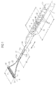
- FIG. 1 and 3 now show a state of the device in which the actuator 10 relative to the actuator 20 to the rear, ie away from the front applicator element 3, is shifted, so that the front end 12A of the bearing portion 12 of the first actuator 10 relative to the front end 22A of the bearing portion 22 of the second actuating element 20 is shifted by a preferably maximum displacement .DELTA.L to the rear or offset.
- the second holding element 23 connected to the connection point P2 and the second end 32 of the applicator element 3 located there is in particular shorter, preferably around the (maximum) displacement .DELTA.L formed as the first holding element 13, which is connected to the first end 31 via the first connection point P1 the applicator element 3 is connected.
- the applicator axis A and, correspondingly, the connecting line between the connection points P1 and P2 or the ends 31 and 32 of the applicator element 3 are set perpendicularly or transversely to the longitudinal axis LA or to the direction of the displacement movement V.
- the two holding elements 13 and 23 are now preferably arranged substantially symmetrically and convexly bent outwards.
- This is opposite FIG. 1 and 3 in the in FIG. 2 shown position of the connection point P2 pulled backwards and the applicator axis A is almost parallel to the longitudinal axis LA, so that the applicator element 3 occupies an approximately longitudinal position.
- the two holding elements 13 and 23 are arranged almost parallel to one another and to the direction of the displacement movement V or longitudinal axis LA.
- connection points P1 and P2 move relative to each other so that a pivoting movement and various oblique positions or positions of the applicator element 3 and its applicator axis A come about (not shown in the FIG).
- the holding elements 13 and 23 are bendable with respect to the lateral or transverse direction, but with respect to the axial direction at least for the applicable forces compressive and tensile, especially wire-like and / or formed of metal, plastic or composites, in particular of the same material and in one piece with the respective actuating element 10 and 20 or at least its bearing section 12 or 22, on which the holding element 13 or 23 is fixed.
- a gap or gap is further formed in all the embodiments shown.
- At least one guide body is arranged, which also moves relative to each other in the relative displacement movement V of the two actuating elements 10 and 20, preferably in a rotational movement about an axis of rotation or about a pivot point, and thereby for guiding the two actuating elements 10 and 20 serves each other and as a spacer the space between the two actuators 10 and 20 is maintained.
- the actuating elements 10 and 20, in particular the grip sections 11 and 21, are preferably spaced apart from each other by a constant distance d so that their inner surfaces are parallel, for example flat as shown and parallel to the longitudinal axis LA extending and elongated, or the space is the same width.
- the guide body can serve in particular to hold this distance d.
- a gear 4 is rotatable in a rotational movement DB about a rotational axis DA and has offset on its outer circumference in the circumferential direction or direction of rotation or evenly distributed teeth 40.
- the axis of rotation DA is preferably directed perpendicular to the longitudinal axis LA or to the displacement movement V and is preferably located on the longitudinal axis LA.
- each actuator 10 and 20 in particular each handle portion 11 and 21, one, preferably parallel to the longitudinal axis LA by a length Z extending row of tooth engagement openings 14 and 24 is provided for engagement of the teeth 40 of the gear 4.
- the length Z. limits the movement of the gear 4 and thus the displacement movement V.
- the transverse extent of the individual tooth engagement openings 14 and 24 perpendicular to the longitudinal axis LA and the extent parallel to the longitudinal axis LA is adapted to the corresponding dimensions of the teeth 40 of the gear 4, so that in each case a tooth 40 can engage in a tooth engagement opening 14 and 24 respectively.
- the tooth engagement openings 14 and 24 may as shown as recesses or depressions or indentations on the mutually facing inner surfaces of the handle portions 11 and 21 or other portions of the actuators 10 and 20 may be formed or as from the inside to the outside through holes or holes or slots then also visible from the outside and possibly be felt.
- the tooth engagement openings 14 and 24 and the teeth 40 are in particular formed approximately rectangular.
- the axial distance of the tooth engagement openings 14 and 24 is adapted to the angular spacing of the teeth 40 of the gear 4.
- at least two teeth 40 are always on opposite sides of the gear 4 in each case a tooth engagement opening 14 and 24 of the two opposite Actuators 10 and 20 engaged and thereby the gear 4 always held firmly between the two actuators 10 and 20 so that it can not fall out.
- the gear 4 is designed to achieve radial restoring forces and thus a higher friction in the tooth engagement openings 14 and 24 elastically, in particular made of an elastic material such as an elastomer and preferably, to increase the elasticity, additionally hollow inside formed by, for example, a ring body 41st is provided for the gear 4, on which the teeth 40 are formed on the outside, or by the gear 4 of a only silhouette or contour defining, corresponding to the outer contour bent or shaped band or wire or the like, in which then the Teeth 40 are hollow, shaped.
- the outer diameter of the gear 4 in the region between the teeth 40 is chosen to be larger in particular than the distance d.
- the elastic gear 4 is set in frictional engagement or under bias between the rows formed by the meshing openings 14 and 24 in the actuators 10 and 20, respectively, to increase the friction.
- the 4 and 5 illustrate an embodiment in which as a guide body, a guide ball 5 with a center M, around which it can rotate as a fulcrum and which is preferably located on the longitudinal axis LA, is provided.
- the guide ball 5 is on opposite sides in a ball track or track, in particular guide groove 15 in the actuator Or its handle portion 11 and at the same time in a ball track or guide groove 25 in the actuator 20 and the handle portion 21 into engagement by the diameter of the guide ball 5 is preferably selected to be greater than the distance d of the actuating elements 10 and 20.
- Die Willsnuten 15 und 25 run axially or parallel to the longitudinal axis LA or displacement movement V with a length Z, but may also at least partially have a different and / or curved course, for example in the manner of a slotted guide.
- the guide grooves 15 and 25 may be formed as recesses with a groove bottom or continuously in the form of slots.
- FIG. 4 shows one FIG. 1 and 3 similar position in which the front end 12A of the bearing portion 12 of the first actuating member 10 relative to the front end 22A of the bearing portion 22 of the second actuating member 20 is displaced by a preferably maximum displacement .DELTA.L to the rear and the applicator element 3 is set transversely.
- FIG. 5 shows one FIG. 2 similar position in which the front end 12A of the bearing portion 12 of the first actuator 10 is flush with the front end 22A of the bearing portion 22 of the second actuator 20 and the applicator element 3 is set almost longitudinally. Again, the oblique or inclined intermediate positions of the applicator element 3 in the sliding movement V are possible again.
- the guide is smoother than with a gear, but does not realize a locking function without further action.
- an additional latching mechanism with gradual locking such stepwise locking.
- recesses on one side and possibly opposite elevations or depressions on both sides in the ball tracks or guide grooves 15 and 25 a certain locking or locking can be provided by the guide ball 5 enters the higher resistance formed thereby regions or from it expires.
- the outermost distance of the opposing guide grooves 15 and 25 in the region of the recesses should remain smaller than the outer diameter of the guide ball 5 so that it does not fall out. It can also be used a prestressed elastic ball 5, which would then expand into the wells by the elastic restoring force.
- the gear 4 and the guide ball 5 respectively hold the grip portions 11 and 21 of the actuators 10 and 20 at a distance and allow good positive guidance of the two actuators against each other by the guide by the engagement in the Zahneingriffsö Maschinens Herbertn or the engagement or guide grooves 15 and 25th
- FIGS. 13 to 15 show an embodiment of such a variant with two layers of gears between each outer actuator 10 or 20 and an inner or middle actuator 50, namely a plurality, in particular three, in the direction of the sliding movement V successively arranged gears 404 to 406 in the space with the distance d1 between the actuators 10 and 50 and a plurality, in particular three, in the direction of the sliding movement V successively arranged gears 401 to 403 in the space with the distance d2 between the actuators 20 and 50th
- An intermediate member 51 of the middle operating member 50 is disposed between the grip portions 11 and 21.
- the central actuating element 50 has at least one row of tooth engagement openings 54 for the teeth 40 of the gears 401 to 406, wherein the teeth 40 engage again on the other side in tooth engagement openings 14 and 24 of the actuating elements 10 and 20 respectively ,
- the middle actuating element 50 continues from the intermediate element 51 forward, in particular axially to the longitudinal axis LA, into a bearing section 52, which is arranged between the bearing sections 12 and 22 of the actuating elements 10 and 20, so that a common axially displaceable mounting of the three actuating elements 10, 20 and 50 in this area, in particular via the bearing surfaces 12B and 22B and corresponding bearing surfaces on the bearing portion 52 is achieved.
- a guide provided with a guide projection 22C on the bearing portion 22, which guide projection 22C by a guide groove 52C in the bearing portion 52 through positively, for example, as shown by means of a double barb or an armature shape or a T-shape, engages in a correspondingly shaped guide groove 12C in the bearing portion 12 and thus the three actuators 10, 20 and 50 in the sliding movement V slidably leads against each other, but perpendicular to the sliding movement V holds each other.
- the guide groove 12C has a rear stopper 12D and a front stopper 12E for the guide projection 22C for securing or limiting the displacement amount ⁇ L, if necessary.
- a projection, e.g. Pin or nose, provided in a groove in the other actuator, e.g. 20 is provided on the opposite inner side and on the one hand holds the distance d and on the other hand ensures an axial guidance in the feed movement V.
- the applicator element 3 In addition to a change in position, a change in shape of the applicator element 3 is possible with the displacement mechanism according to the invention, in particular the actuating elements 10 and 20 and holding elements 13 and 23.
- the applicator element 3 for example, be less rigid, so that it can bend relative to the applicator axis A and thereby assume a curved shape, and in coordination with the flexibility of the holding elements 13 and 23 could by the sliding movement V a curvature or convex or concave shape of the applicator element 3 can be achieved.
- At least one additional retaining element eg retaining pin, central web
- at least one additional retaining element eg retaining pin, central web
- Such an additional holding element 53 is in one embodiment in the already mentioned FIG. 13 and 14 shown and formed there in particular in the front region of the central actuator 50 and joins the front of the bearing portion 52 at. There, the holding element 53 supports a middle region or inner region 33 of the applicator element 3 at a tip or a front end via a third connection point P3.
- FIG. 13 now shows a position in which the front end 22A of the bearing portion 22 of the second actuating element 22 is offset by the displacement .DELTA.L relative to the front end 12A of the bearing portion 12 of the first actuating element 10 to the front or moved. This creates a position and shape of the applicator element 3 with respect to the first connection point P1 forward approximately to the axial position of the third connection point P3 offset second connection point P2.
- a transversely aligned portion of the applicator element 3 extends from the inner region 33 to the second end 32 and between the third connection point P3 and the first connection point P1 an obliquely to almost longitudinally rearwardly directed Part of the applicator element 3 from the inner region 33 to the first end 32, so that approximately an L-shape of the applicator element 3 results.
- FIG. 14 shows a position in which the front end 22A of the bearing portion 22 of the second actuating element 22 is disposed or displaced approximately at the same axial position or flush with the front end 12A of the bearing portion 12 of the first actuating element 10. This creates a position and shape of the applicator element 3 with respect to the third connection point P3 axially offset by the same way to the rear first connection point P1 and second connection point P2.
- an obliquely to almost longitudinally rearwardly oriented partial region of the applicator element 3 extends from the inner region 33 to the first end 32 or second end, so that approximately gives a V-shape of the applicator element 3.
- the actuators 10 and 20 and possibly 50 via a folding multiple hinge or a film multiple hinge with each arranged one behind the other, respectively against each other about one axis of rotation pivoting or hinged or rotatable segments against each other, with one or two or more segments in a row ,
- axially to the displacement movement V or longitudinal axis LA can be arranged and thereby different locking positions can be realized.
- the other segment (s) are then pivoted to that row, similar to a track (curb chain) or segment chain.
- the locking of the segments in the different locking positions can be supported by corresponding corresponding stops and / or by magnets.
Landscapes
- Brushes (AREA)
Applications Claiming Priority (1)
| Application Number | Priority Date | Filing Date | Title |
|---|---|---|---|
| DE102014117994.3A DE102014117994A1 (de) | 2014-12-05 | 2014-12-05 | Vorrichtung, insbesondere zum Auftragen von Kosmetika |
Publications (2)
| Publication Number | Publication Date |
|---|---|
| EP3028599A1 true EP3028599A1 (fr) | 2016-06-08 |
| EP3028599B1 EP3028599B1 (fr) | 2019-03-06 |
Family
ID=54782624
Family Applications (1)
| Application Number | Title | Priority Date | Filing Date |
|---|---|---|---|
| EP15198077.8A Active EP3028599B1 (fr) | 2014-12-05 | 2015-12-04 | Dispositif notamment pour appliquer un produit cosmetique |
Country Status (2)
| Country | Link |
|---|---|
| EP (1) | EP3028599B1 (fr) |
| DE (1) | DE102014117994A1 (fr) |
Cited By (1)
| Publication number | Priority date | Publication date | Assignee | Title |
|---|---|---|---|---|
| WO2017053661A1 (fr) * | 2015-09-24 | 2017-03-30 | Worldwide Packaging Inc. | Applicateur de fluide |
Citations (9)
| Publication number | Priority date | Publication date | Assignee | Title |
|---|---|---|---|---|
| US4428388A (en) | 1981-11-06 | 1984-01-31 | Cassai Gino H | Adjustable cosmetic wand |
| WO2004077987A1 (fr) | 2003-03-05 | 2004-09-16 | Laline International Sarl | Applicateur de fard a cils avec branches mobiles |
| EP1593320A1 (fr) | 2004-05-07 | 2005-11-09 | L'oreal | Applicateur et dispositif de conditionnement et de distribution comportant un tel applicateur |
| FR2872006B1 (fr) | 2004-06-29 | 2006-07-28 | Techpack Int Sa | Brosse de maquillage a courbure variable |
| EP2084986A2 (fr) | 2008-02-04 | 2009-08-05 | Zen Design Solutions Limited | Applicateur réglable |
| EP2198743A1 (fr) | 2008-12-15 | 2010-06-23 | L'oreal | Applicateur pour appliquer un produit sur les matières kératiniques |
| US20120160262A1 (en) | 2010-12-27 | 2012-06-28 | Lvmh Recherche | Cosmetic Applicator, A Makeup Kit Including Such an Applicator, and Use of Such a Kit |
| US20120195672A1 (en) | 2011-01-31 | 2012-08-02 | Li-Chun Chan | Bendable mascara brush |
| JP2013081661A (ja) | 2011-10-11 | 2013-05-09 | Shiseido Co Ltd | 化粧用部材の可動機構 |
-
2014
- 2014-12-05 DE DE102014117994.3A patent/DE102014117994A1/de not_active Withdrawn
-
2015
- 2015-12-04 EP EP15198077.8A patent/EP3028599B1/fr active Active
Patent Citations (9)
| Publication number | Priority date | Publication date | Assignee | Title |
|---|---|---|---|---|
| US4428388A (en) | 1981-11-06 | 1984-01-31 | Cassai Gino H | Adjustable cosmetic wand |
| WO2004077987A1 (fr) | 2003-03-05 | 2004-09-16 | Laline International Sarl | Applicateur de fard a cils avec branches mobiles |
| EP1593320A1 (fr) | 2004-05-07 | 2005-11-09 | L'oreal | Applicateur et dispositif de conditionnement et de distribution comportant un tel applicateur |
| FR2872006B1 (fr) | 2004-06-29 | 2006-07-28 | Techpack Int Sa | Brosse de maquillage a courbure variable |
| EP2084986A2 (fr) | 2008-02-04 | 2009-08-05 | Zen Design Solutions Limited | Applicateur réglable |
| EP2198743A1 (fr) | 2008-12-15 | 2010-06-23 | L'oreal | Applicateur pour appliquer un produit sur les matières kératiniques |
| US20120160262A1 (en) | 2010-12-27 | 2012-06-28 | Lvmh Recherche | Cosmetic Applicator, A Makeup Kit Including Such an Applicator, and Use of Such a Kit |
| US20120195672A1 (en) | 2011-01-31 | 2012-08-02 | Li-Chun Chan | Bendable mascara brush |
| JP2013081661A (ja) | 2011-10-11 | 2013-05-09 | Shiseido Co Ltd | 化粧用部材の可動機構 |
Cited By (1)
| Publication number | Priority date | Publication date | Assignee | Title |
|---|---|---|---|---|
| WO2017053661A1 (fr) * | 2015-09-24 | 2017-03-30 | Worldwide Packaging Inc. | Applicateur de fluide |
Also Published As
| Publication number | Publication date |
|---|---|
| EP3028599B1 (fr) | 2019-03-06 |
| DE102014117994A1 (de) | 2016-06-09 |
Similar Documents
| Publication | Publication Date | Title |
|---|---|---|
| EP2266434B1 (fr) | Applicateur cosmétique doté d'applicateurs situés à l'intérieur, pouvant sortir de manière coulissante et rotatifs | |
| EP2974619B1 (fr) | Brosse interdentaire, procede de fabrication d'une brosse interdentaire et groupe de produit a partir de plusieurs brosses interdentaires | |
| EP1121034B1 (fr) | Brosse, en particulier brosse a dents | |
| DE2550265C3 (de) | Haarbürste | |
| DE202010010860U1 (de) | Applikator und Kosmetikeinheit aufweisend den Applikator | |
| EP2632292A1 (fr) | Dispositif applicateur pour appliquer un cosmétique, élément applicateur à cet effet ainsi qu'unité cosmétique présentant le dispositif applicateur | |
| EP2696741B1 (fr) | Dispositif de commande | |
| EP1607020B1 (fr) | Applicateur avec une rainure de ventilation | |
| DE19911763A1 (de) | Applikatorbürste für flüssige oder pastöse Mittel, insbesondere für dekorative Kosmetika wie Mascara | |
| DE3608064A1 (de) | Applikatorbehaelter fuer ein kosmetisches produkt | |
| DE7837933U1 (de) | Behaelter mit einem auftragselement fuer kosmetische fluessigkeiten | |
| EP0813374A1 (fr) | Articles de brosserie tels que brosses, pinceaux ou similaires | |
| DE102009025443B4 (de) | Blutlanzettenvorrichtung mit Stechtiefeneinstellung | |
| DE3513814A1 (de) | Geraet zum partiellen einfaerben von haaren | |
| WO1993016617A1 (fr) | Brosse a mascara | |
| DE102009013233A1 (de) | Auftragvorrichtung zum Auftragen einer kosmetischen und/oder pharmazeutischen Masse, insbesondere Mascara | |
| DE202010000381U1 (de) | Behältnis | |
| EP3028599B1 (fr) | Dispositif notamment pour appliquer un produit cosmetique | |
| EP3500129B1 (fr) | Dispositif d'application d'un milieu liquide | |
| EP3174432A1 (fr) | Applicateur comprenant des poils composés d'une matière plastique remplie de particules | |
| DE102013112800B3 (de) | Zahnbürste mit einem Borstenfeld und mit einer Interdentalbürste | |
| DE102012018467B4 (de) | Verfahren zur Herstellung eines Applikators für kosmetische Produkte und ein Applikator | |
| WO2013056699A1 (fr) | Dispositif pouvant être tenu à la main pour la au moins une aiguille de tatouage d'une machine à tatouer | |
| WO2009065562A2 (fr) | Brosse pour transférer des produits liquides ou pâteux | |
| DE2750498A1 (de) | Haarbuerste |
Legal Events
| Date | Code | Title | Description |
|---|---|---|---|
| PUAI | Public reference made under article 153(3) epc to a published international application that has entered the european phase |
Free format text: ORIGINAL CODE: 0009012 |
|
| AK | Designated contracting states |
Kind code of ref document: A1 Designated state(s): AL AT BE BG CH CY CZ DE DK EE ES FI FR GB GR HR HU IE IS IT LI LT LU LV MC MK MT NL NO PL PT RO RS SE SI SK SM TR |
|
| AX | Request for extension of the european patent |
Extension state: BA ME |
|
| 17P | Request for examination filed |
Effective date: 20160707 |
|
| RBV | Designated contracting states (corrected) |
Designated state(s): AL AT BE BG CH CY CZ DE DK EE ES FI FR GB GR HR HU IE IS IT LI LT LU LV MC MK MT NL NO PL PT RO RS SE SI SK SM TR |
|
| RAP1 | Party data changed (applicant data changed or rights of an application transferred) |
Owner name: GEKA GMBH |
|
| GRAP | Despatch of communication of intention to grant a patent |
Free format text: ORIGINAL CODE: EPIDOSNIGR1 |
|
| STAA | Information on the status of an ep patent application or granted ep patent |
Free format text: STATUS: GRANT OF PATENT IS INTENDED |
|
| INTG | Intention to grant announced |
Effective date: 20180418 |
|
| GRAJ | Information related to disapproval of communication of intention to grant by the applicant or resumption of examination proceedings by the epo deleted |
Free format text: ORIGINAL CODE: EPIDOSDIGR1 |
|
| STAA | Information on the status of an ep patent application or granted ep patent |
Free format text: STATUS: REQUEST FOR EXAMINATION WAS MADE |
|
| GRAP | Despatch of communication of intention to grant a patent |
Free format text: ORIGINAL CODE: EPIDOSNIGR1 |
|
| STAA | Information on the status of an ep patent application or granted ep patent |
Free format text: STATUS: GRANT OF PATENT IS INTENDED |
|
| INTC | Intention to grant announced (deleted) | ||
| INTG | Intention to grant announced |
Effective date: 20180910 |
|
| GRAS | Grant fee paid |
Free format text: ORIGINAL CODE: EPIDOSNIGR3 |
|
| GRAA | (expected) grant |
Free format text: ORIGINAL CODE: 0009210 |
|
| STAA | Information on the status of an ep patent application or granted ep patent |
Free format text: STATUS: THE PATENT HAS BEEN GRANTED |
|
| AK | Designated contracting states |
Kind code of ref document: B1 Designated state(s): AL AT BE BG CH CY CZ DE DK EE ES FI FR GB GR HR HU IE IS IT LI LT LU LV MC MK MT NL NO PL PT RO RS SE SI SK SM TR |
|
| REG | Reference to a national code |
Ref country code: GB Ref legal event code: FG4D Free format text: NOT ENGLISH |
|
| REG | Reference to a national code |
Ref country code: CH Ref legal event code: EP Ref country code: AT Ref legal event code: REF Ref document number: 1103401 Country of ref document: AT Kind code of ref document: T Effective date: 20190315 |
|
| REG | Reference to a national code |
Ref country code: DE Ref legal event code: R096 Ref document number: 502015008217 Country of ref document: DE |
|
| REG | Reference to a national code |
Ref country code: IE Ref legal event code: FG4D Free format text: LANGUAGE OF EP DOCUMENT: GERMAN |
|
| REG | Reference to a national code |
Ref country code: NL Ref legal event code: MP Effective date: 20190306 |
|
| REG | Reference to a national code |
Ref country code: LT Ref legal event code: MG4D |
|
| PG25 | Lapsed in a contracting state [announced via postgrant information from national office to epo] |
Ref country code: SE Free format text: LAPSE BECAUSE OF FAILURE TO SUBMIT A TRANSLATION OF THE DESCRIPTION OR TO PAY THE FEE WITHIN THE PRESCRIBED TIME-LIMIT Effective date: 20190306 Ref country code: LT Free format text: LAPSE BECAUSE OF FAILURE TO SUBMIT A TRANSLATION OF THE DESCRIPTION OR TO PAY THE FEE WITHIN THE PRESCRIBED TIME-LIMIT Effective date: 20190306 Ref country code: NO Free format text: LAPSE BECAUSE OF FAILURE TO SUBMIT A TRANSLATION OF THE DESCRIPTION OR TO PAY THE FEE WITHIN THE PRESCRIBED TIME-LIMIT Effective date: 20190606 Ref country code: FI Free format text: LAPSE BECAUSE OF FAILURE TO SUBMIT A TRANSLATION OF THE DESCRIPTION OR TO PAY THE FEE WITHIN THE PRESCRIBED TIME-LIMIT Effective date: 20190306 |
|
| PG25 | Lapsed in a contracting state [announced via postgrant information from national office to epo] |
Ref country code: BG Free format text: LAPSE BECAUSE OF FAILURE TO SUBMIT A TRANSLATION OF THE DESCRIPTION OR TO PAY THE FEE WITHIN THE PRESCRIBED TIME-LIMIT Effective date: 20190606 Ref country code: RS Free format text: LAPSE BECAUSE OF FAILURE TO SUBMIT A TRANSLATION OF THE DESCRIPTION OR TO PAY THE FEE WITHIN THE PRESCRIBED TIME-LIMIT Effective date: 20190306 Ref country code: LV Free format text: LAPSE BECAUSE OF FAILURE TO SUBMIT A TRANSLATION OF THE DESCRIPTION OR TO PAY THE FEE WITHIN THE PRESCRIBED TIME-LIMIT Effective date: 20190306 Ref country code: NL Free format text: LAPSE BECAUSE OF FAILURE TO SUBMIT A TRANSLATION OF THE DESCRIPTION OR TO PAY THE FEE WITHIN THE PRESCRIBED TIME-LIMIT Effective date: 20190306 Ref country code: GR Free format text: LAPSE BECAUSE OF FAILURE TO SUBMIT A TRANSLATION OF THE DESCRIPTION OR TO PAY THE FEE WITHIN THE PRESCRIBED TIME-LIMIT Effective date: 20190607 Ref country code: HR Free format text: LAPSE BECAUSE OF FAILURE TO SUBMIT A TRANSLATION OF THE DESCRIPTION OR TO PAY THE FEE WITHIN THE PRESCRIBED TIME-LIMIT Effective date: 20190306 |
|
| PG25 | Lapsed in a contracting state [announced via postgrant information from national office to epo] |
Ref country code: PT Free format text: LAPSE BECAUSE OF FAILURE TO SUBMIT A TRANSLATION OF THE DESCRIPTION OR TO PAY THE FEE WITHIN THE PRESCRIBED TIME-LIMIT Effective date: 20190706 Ref country code: SK Free format text: LAPSE BECAUSE OF FAILURE TO SUBMIT A TRANSLATION OF THE DESCRIPTION OR TO PAY THE FEE WITHIN THE PRESCRIBED TIME-LIMIT Effective date: 20190306 Ref country code: AL Free format text: LAPSE BECAUSE OF FAILURE TO SUBMIT A TRANSLATION OF THE DESCRIPTION OR TO PAY THE FEE WITHIN THE PRESCRIBED TIME-LIMIT Effective date: 20190306 Ref country code: EE Free format text: LAPSE BECAUSE OF FAILURE TO SUBMIT A TRANSLATION OF THE DESCRIPTION OR TO PAY THE FEE WITHIN THE PRESCRIBED TIME-LIMIT Effective date: 20190306 Ref country code: ES Free format text: LAPSE BECAUSE OF FAILURE TO SUBMIT A TRANSLATION OF THE DESCRIPTION OR TO PAY THE FEE WITHIN THE PRESCRIBED TIME-LIMIT Effective date: 20190306 Ref country code: CZ Free format text: LAPSE BECAUSE OF FAILURE TO SUBMIT A TRANSLATION OF THE DESCRIPTION OR TO PAY THE FEE WITHIN THE PRESCRIBED TIME-LIMIT Effective date: 20190306 Ref country code: RO Free format text: LAPSE BECAUSE OF FAILURE TO SUBMIT A TRANSLATION OF THE DESCRIPTION OR TO PAY THE FEE WITHIN THE PRESCRIBED TIME-LIMIT Effective date: 20190306 |
|
| PG25 | Lapsed in a contracting state [announced via postgrant information from national office to epo] |
Ref country code: SM Free format text: LAPSE BECAUSE OF FAILURE TO SUBMIT A TRANSLATION OF THE DESCRIPTION OR TO PAY THE FEE WITHIN THE PRESCRIBED TIME-LIMIT Effective date: 20190306 Ref country code: PL Free format text: LAPSE BECAUSE OF FAILURE TO SUBMIT A TRANSLATION OF THE DESCRIPTION OR TO PAY THE FEE WITHIN THE PRESCRIBED TIME-LIMIT Effective date: 20190306 |
|
| REG | Reference to a national code |
Ref country code: DE Ref legal event code: R097 Ref document number: 502015008217 Country of ref document: DE |
|
| PG25 | Lapsed in a contracting state [announced via postgrant information from national office to epo] |
Ref country code: IS Free format text: LAPSE BECAUSE OF FAILURE TO SUBMIT A TRANSLATION OF THE DESCRIPTION OR TO PAY THE FEE WITHIN THE PRESCRIBED TIME-LIMIT Effective date: 20190706 |
|
| PLBE | No opposition filed within time limit |
Free format text: ORIGINAL CODE: 0009261 |
|
| STAA | Information on the status of an ep patent application or granted ep patent |
Free format text: STATUS: NO OPPOSITION FILED WITHIN TIME LIMIT |
|
| PG25 | Lapsed in a contracting state [announced via postgrant information from national office to epo] |
Ref country code: DK Free format text: LAPSE BECAUSE OF FAILURE TO SUBMIT A TRANSLATION OF THE DESCRIPTION OR TO PAY THE FEE WITHIN THE PRESCRIBED TIME-LIMIT Effective date: 20190306 |
|
| 26N | No opposition filed |
Effective date: 20191209 |
|
| PG25 | Lapsed in a contracting state [announced via postgrant information from national office to epo] |
Ref country code: SI Free format text: LAPSE BECAUSE OF FAILURE TO SUBMIT A TRANSLATION OF THE DESCRIPTION OR TO PAY THE FEE WITHIN THE PRESCRIBED TIME-LIMIT Effective date: 20190306 |
|
| PGFP | Annual fee paid to national office [announced via postgrant information from national office to epo] |
Ref country code: FR Payment date: 20191219 Year of fee payment: 5 |
|
| PG25 | Lapsed in a contracting state [announced via postgrant information from national office to epo] |
Ref country code: TR Free format text: LAPSE BECAUSE OF FAILURE TO SUBMIT A TRANSLATION OF THE DESCRIPTION OR TO PAY THE FEE WITHIN THE PRESCRIBED TIME-LIMIT Effective date: 20190306 |
|
| PGFP | Annual fee paid to national office [announced via postgrant information from national office to epo] |
Ref country code: GB Payment date: 20191220 Year of fee payment: 5 |
|
| REG | Reference to a national code |
Ref country code: CH Ref legal event code: PL |
|
| REG | Reference to a national code |
Ref country code: BE Ref legal event code: MM Effective date: 20191231 |
|
| PG25 | Lapsed in a contracting state [announced via postgrant information from national office to epo] |
Ref country code: MC Free format text: LAPSE BECAUSE OF FAILURE TO SUBMIT A TRANSLATION OF THE DESCRIPTION OR TO PAY THE FEE WITHIN THE PRESCRIBED TIME-LIMIT Effective date: 20190306 |
|
| PG25 | Lapsed in a contracting state [announced via postgrant information from national office to epo] |
Ref country code: LU Free format text: LAPSE BECAUSE OF NON-PAYMENT OF DUE FEES Effective date: 20191204 Ref country code: IE Free format text: LAPSE BECAUSE OF NON-PAYMENT OF DUE FEES Effective date: 20191204 Ref country code: IT Free format text: LAPSE BECAUSE OF NON-PAYMENT OF DUE FEES Effective date: 20191204 |
|
| PG25 | Lapsed in a contracting state [announced via postgrant information from national office to epo] |
Ref country code: LI Free format text: LAPSE BECAUSE OF NON-PAYMENT OF DUE FEES Effective date: 20191231 Ref country code: BE Free format text: LAPSE BECAUSE OF NON-PAYMENT OF DUE FEES Effective date: 20191231 Ref country code: CH Free format text: LAPSE BECAUSE OF NON-PAYMENT OF DUE FEES Effective date: 20191231 |
|
| PG25 | Lapsed in a contracting state [announced via postgrant information from national office to epo] |
Ref country code: CY Free format text: LAPSE BECAUSE OF FAILURE TO SUBMIT A TRANSLATION OF THE DESCRIPTION OR TO PAY THE FEE WITHIN THE PRESCRIBED TIME-LIMIT Effective date: 20190306 |
|
| PG25 | Lapsed in a contracting state [announced via postgrant information from national office to epo] |
Ref country code: MT Free format text: LAPSE BECAUSE OF FAILURE TO SUBMIT A TRANSLATION OF THE DESCRIPTION OR TO PAY THE FEE WITHIN THE PRESCRIBED TIME-LIMIT Effective date: 20190306 Ref country code: HU Free format text: LAPSE BECAUSE OF FAILURE TO SUBMIT A TRANSLATION OF THE DESCRIPTION OR TO PAY THE FEE WITHIN THE PRESCRIBED TIME-LIMIT; INVALID AB INITIO Effective date: 20151204 |
|
| GBPC | Gb: european patent ceased through non-payment of renewal fee |
Effective date: 20201204 |
|
| PG25 | Lapsed in a contracting state [announced via postgrant information from national office to epo] |
Ref country code: FR Free format text: LAPSE BECAUSE OF NON-PAYMENT OF DUE FEES Effective date: 20201231 |
|
| PG25 | Lapsed in a contracting state [announced via postgrant information from national office to epo] |
Ref country code: GB Free format text: LAPSE BECAUSE OF NON-PAYMENT OF DUE FEES Effective date: 20201204 |
|
| REG | Reference to a national code |
Ref country code: AT Ref legal event code: MM01 Ref document number: 1103401 Country of ref document: AT Kind code of ref document: T Effective date: 20201204 |
|
| PG25 | Lapsed in a contracting state [announced via postgrant information from national office to epo] |
Ref country code: AT Free format text: LAPSE BECAUSE OF NON-PAYMENT OF DUE FEES Effective date: 20201204 |
|
| PG25 | Lapsed in a contracting state [announced via postgrant information from national office to epo] |
Ref country code: MK Free format text: LAPSE BECAUSE OF FAILURE TO SUBMIT A TRANSLATION OF THE DESCRIPTION OR TO PAY THE FEE WITHIN THE PRESCRIBED TIME-LIMIT Effective date: 20190306 |
|
| PGFP | Annual fee paid to national office [announced via postgrant information from national office to epo] |
Ref country code: DE Payment date: 20231214 Year of fee payment: 9 |