EP3028562A1 - Quaderballenpresse - Google Patents
Quaderballenpresse Download PDFInfo
- Publication number
- EP3028562A1 EP3028562A1 EP15194880.9A EP15194880A EP3028562A1 EP 3028562 A1 EP3028562 A1 EP 3028562A1 EP 15194880 A EP15194880 A EP 15194880A EP 3028562 A1 EP3028562 A1 EP 3028562A1
- Authority
- EP
- European Patent Office
- Prior art keywords
- knotter
- square baler
- baler according
- flow guide
- flap
- Prior art date
- Legal status (The legal status is an assumption and is not a legal conclusion. Google has not performed a legal analysis and makes no representation as to the accuracy of the status listed.)
- Granted
Links
Images

Classifications
-
- A—HUMAN NECESSITIES
- A01—AGRICULTURE; FORESTRY; ANIMAL HUSBANDRY; HUNTING; TRAPPING; FISHING
- A01F—PROCESSING OF HARVESTED PRODUCE; HAY OR STRAW PRESSES; DEVICES FOR STORING AGRICULTURAL OR HORTICULTURAL PRODUCE
- A01F15/00—Baling presses for straw, hay or the like
- A01F15/08—Details
- A01F15/14—Tying devices specially adapted for baling presses
- A01F15/145—Twine knotters
Definitions
- the present invention relates to a square baler for forming bales of agricultural crop.
- a square baler conventionally comprises a plunger which reciprocates in a press channel to compact crop introduced into the press channel therein, and a knotter for knotting a twine strand by which a bale fully formed in the press channel is held together.
- the wall of the press channel has slots through which the twine is passed. Through these slots small fragments of the crop can escape during the compression process and settle outside the press channel, in particular at the knotter, and impair its functioning.
- a square baler in which an outlet nozzle of a fan is arranged adjacent to a knotter to direct an air flow to the knotter.
- the deposition of crop fragments at the knotter can be slowed down with such an air flow, it is not possible to completely prevent them, so that the operation of the square baling press from time to time succeeds must be interrupted to clean the knotter. This affects the productivity of the baler. Therefore, it is desirable to be able to make the time intervals between two purges of the knot as long as possible. Although this succeeds to some extent by an increase in the flow rate, but the powerful blower required for this is expensive and requires a lot of drive energy, which in turn impairs the economy.
- Object of the present invention is therefore to provide a square baler, in which even at low power of a fan long time intervals between two purges of Knoter can be achieved.
- the object is achieved by the flow guide between a first position in which it directs a blown air stream of the blower on the first knotter, and at least a second in a square baler with a press channel, arranged on the press channel first knotter, a fan and a flow Movable position in which it passes the blown air flow past the first knotter.
- Particles that have settled in the knotter are thus alternately exposed to the tensile force of the blast air flow or stationary air. This change promotes movements of the particles, which make it easier for particles that are stuck to detach from the knotter.
- it is possible to effectively delay the growth of a particle layer on the knotter.
- the flow guide can direct the Blas Kunststoffstrom expediently to a second Knoter.
- further knotter may be arranged so that they are detected in an intermediate position between the first and the second position of the blast air flow. So a single blower is sufficient to prevent or delay the deposition of particles on several knotters.
- the baling press can have at least two flow guide elements, with each knotter being assigned exactly one of the flow guide elements for directing the blown air flow onto the knotter.
- the amount of crop particles escaping from the squeeze channel is variable during a cycle of movement of the squeeze piston. The strongest is the escape of particles towards the end of a pressing movement. It would be desirable to be able to blow these particles away before they have the opportunity to settle on a surface of the press, in particular on a knotter. The longer the time interval between the exit of the particles from the press channel and their detection by the blast air flow, the more particles settle in the meantime. So that this does not lead to premature contamination of a single Knoters, why the operation of the square baler would have to be interrupted, even if other knotters are not so heavily polluted, the periods of the flow guide and the plunger are in a non-integer ratio. This ensures that the time interval between the maximum of the particle outlet and the detection of the knotter at each knotter fluctuates through the blown air flow and is the same on average for all knotters.
- the movements of the plunger and the flow guide can be synchronized with each other so that in each case the same position of the plunger in different periods of piston movement, the flow guide alternately occupies the first and second positions.
- This piston position may be that at which the exit rate of the particles from the press channel is maximum, or immediately follow this maximum.
- the flow guide may comprise at least one pivotable flap; preferably several coupled provided in the same direction hinged flaps.
- the at least one flap can be arranged at the outlet of an air guide tube.
- the at least one flap is separated from the knotters by a gap free from air-bearing internals.
- the blast air flow can continuously swing back and forth between the first and second knotters and also prevent particle deposits between the knots.
- the swing speed of the flap may be lower in the first and second positions than in an intermediate position, thereby increasing the time that the first and second knots are exposed to the blast air flow, again counteracting rapid soiling of the first and second knots.
- the third knotter may be a third knotter, which is exposed to the blast air in the intermediate position. Although the period of time during which it is exposed to the blast air flow is shorter than that of the first and second knots, in contrast to these, the third knotter is twice captured by the blast air flow in each period of the movement of the flow guide element and thus efficiently kept clean.
- Such a variable-speed pivoting movement of the flap can be driven in a simple manner by an eccentric.
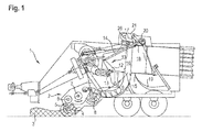
- baler 1 is designed as a trailer for coupling to a towing vehicle, not shown, but the invention is of course applicable to a self-propelled baler.
- a pick-up device 2 of the baler also referred to as a pickup, is used to pick up crop 3 from the ground.
- the picking device 2 comprises a collecting drum 4, which is equipped with projecting tines and which is rotationally driven in such a direction that it pushes the crop 3 on the ground in front of it, lifting it and pulling it into a gap defined by rollers 5, 6 of a blank holder.
- An arranged at the end of the gap screw roller 7 is occupied by two screws of opposite rotation, which push the crop together to the center of the baler and a cutting rotor 8 feed.
- Stationary knives engage in spaces of the cutting rotor 8 to crush the crop. The crushed crop is fed by the rotation of the cutting rotor 8 a collecting channel 9.
- the collecting channel 9 is bounded at the top by a convexly curved ceiling provided with longitudinal slots, by means of which tines 11 of a gatherer 10 can engage in the channel 9.
- the tines 11 are attached to a two-armed lever 12, of which a pivot, driven and guided by a crank arm 13, rotates at a first frequency about an axis of rotation of the crank arm 13, while an attacking at one of the tines 11 end of the lever 12 attacking Handlebar 14 with an integer fraction 1 / n, for example, half or one third, the frequency of the arm 13 is driven.
- arm 13 and handlebar 14 causes the prongs 11 periodically (in n different ways) to pass through the collecting channel 9 and thereby pressed by the cutting rotor 8 crop against a flank 15 of a guided in a press channel 16 pressing piston 17 and pre-compress , During the nth movement of the tines 11, the pressing piston 17, as shown in the figure, retracted forwards in the pressing channel 16, so that the tines 11 push the crop into the pressing channel 16.
- the pressing piston 17 is driven to oscillate at the same frequency as the handlebar 14 in order to press the newly supplied crop against a bale 18 being formed, so that this with each stroke of the plunger 17 grows a bit far and is moved in the press channel 16 to the rear.
- a knotter assembly 21 is arranged with a plurality of knots 20 distributed across the width of the pressing channel 16. Each of these knotter 20 fixes the end of a twine strand, each extending through a slot on the top of the press channel 16, on the backside of the bale 18 facing away from the piston 17 and through slots in the bottom of the press channel to a binding needle 19.
- Fig. 2 shows the Knoterbauen 21 in a perspective view obliquely from above. Between two oriented in the direction of travel of the baler side walls 22 two coupled via a gear shafts 23, 24 are rotatably mounted.
- the wave 23 drives the movement of the (in Fig. 2 not shown) handlebar 14, the other shaft 24 carries a plurality of bevel gears 25, here six pieces, each driving one of the knotter 20.
- a fan 26 in a front region of the knotter assembly 21 includes an electric or hydraulic motor 27 which drives centrifugal rotors in two cylindrical housings 29 via a common shaft 28.
- Each of the housings 29 extends an air guide tube 30 rearwardly in the direction of the knotter 20.
- the air guide tubes 30 each pass below the shaft 23, so that the air flow ejected from them closely above the (in Fig. 2 not shown) sweeps the top of the press channel 16 and prevents the deposition of particles there.
- each blown air duct 30 At an outlet opening of each blown air duct 30, an arrangement of here three coupled and in the same direction pivotable flaps 32 is provided as a flow guide 31.
- the groups of flaps 32 are each pivotally driven by an electric motor 33; she but could also be coupled by a gear to the rotation of the shaft 23.
- the flaps 32 are separated from the knotters 20 by a free space 34, the width of which is chosen according to the pivoting freedom of the flaps 32 so that 30 alternately three knotter 20 can be blown on each Blas Kunststoffkanal.
- Fig. 3 shows a schematic plan view of the flaps 32 at the end of one of the two Blas Kunststoffkanäle 30 and three of these flaps 32 opposite knotter, here for better distinction called Knoter 20a, 20b, 20c.
- the flaps 32 are each pivotally mounted at its end associated with the blast air duct 30 about a vertical axis 35 and coupled to each other by a rod 36.
- a plane 37 extending centrally between the main sides of the middle flap 32 crosses the knotter 20b, and the blown air stream expelled from the blower 26, indicated by an arrow 38, strikes the knotter 20b while the flow rate of ventilation at the knotters 20a, 20c is low.
- An eccentric 39 is formed by a wheel 41 rotatably driven by the electric motor 33 about an axis 40 and a pin 42, which engages offset against the axis 40 in a gate 43 on one of the flaps 32.
- Turning the wheel 41 clockwise by approx. 90 ° places the flaps in the in Fig. 3 dashed line position in which the plane 37 crosses the knotter 20c and the Blas Kunststoffstrom 38 is ejected in the direction of this Knoters.
- a rotation of the wheel 41 by a further 90 ° brings the flaps 32 in the drawn with solid lines position back; after further 90 ° rotations they take a not specifically shown in the figure, to the dashed lined mirror image position in which the plane 37 passes through the knotter 20a.
- the flaps 32 should completely pass through their swing angle range during a period of movement of the piston, ie the period of pivotal movement of the flaps 32 should be a maximum of two times be long as the period of the piston movement. Preferably, it is just as long as the period of the piston movement or even shorter, so that the pivoting angle range is completely traversed during a pressing movement of the piston 17.
- the phases of the movements of flaps 32 and plunger 17 can be coordinated so that at the position of the plunger 17, in which the exit of particles from the pressure channel 16 reaches its maximum, the blast air 38 each alternately on the knotter 20 a and the knotter 20c is directed. If the period of the flap movement is twice as long as that of the piston movement, this is the case in respectively immediately consecutive periods of the piston movement. Thus, both knots are equally well protected against the deposition of particles, and also the knotter 20b is effectively kept clean because it is blown once in each period of the plunger movement.
- the period of the plate movement is set to 4/3 or 4/5 of the period of the plunger movement, so that the eccentric 39 makes 3/4 or 5/4 revolutions in each period of the plunger movement. This ensures that in each period of the piston movement, all knotters are at least blown once, and it is possible to synchronize the movements of the piston and the flaps so that at the time of maximum particle leakage all three knotters are alternately blown.
Landscapes
- Life Sciences & Earth Sciences (AREA)
- Environmental Sciences (AREA)
- Fodder In General (AREA)
- Structures Of Non-Positive Displacement Pumps (AREA)
- Catching Or Destruction (AREA)
- Preliminary Treatment Of Fibers (AREA)
- Spinning Or Twisting Of Yarns (AREA)
Abstract
Description
- Die vorliegende Erfindung betrifft eine Quaderballenpresse zum Formen von Ballen aus landwirtschaftlichem Erntegut. Eine solche Quaderballenpresse umfasst herkömmlicherweise einen Presskolben, der in einem Presskanal hin und her beweglich ist, um in den Presskanal eingeführtes Erntegut darin zu verdichten, sowie einen Knoter zum Verknoten eines Bindegarnstrangs, durch den ein in dem Presskanal fertig geformter Ballen zusammengehalten wird. Die Wand des Presskanals weist Schlitze auf, durch die das Bindegarn hindurchgeführt ist. Durch diese Schlitze können kleine Bruchstücke des Ernteguts während des Verdichtungsvorgangs entweichen und sich außerhalb des Presskanals, insbesondere am Knoter, absetzen und dessen Funktionsfähigkeit beeinträchtigen.
- Aus
US 3 020 829 ist eine Quaderballenpresse bekannt, bei der benachbart zu einem Knoter eine Austrittsdüse eines Gebläses angeordnet ist, um einen Luftstrom auf den Knoter zu richten. Mit einem solchen Luftstrom kann zwar die Ablagerung von Erntegutbruchstücken am Knoter verlangsamt werden, sie völlig zu verhindern gelingt jedoch nicht, so dass der Betrieb der Quaderballenpresse von Zeit zu Zeit unterbrochen werden muss, um den Knoter zu reinigen. Dies beeinträchtigt die Produktivität der Ballenpresse. Deshalb ist es wünschenswert, die Zeitintervalle zwischen zwei Säuberungen des Knoters möglichst lang machen zu können. Dies gelingt zwar in gewissem Umfang durch eine Steigerung der Strömungsgeschwindigkeit, doch das dafür benötigte leistungsstarke Gebläse ist teuer und benötigt viel Antriebsenergie, was wiederum die Wirtschaftlichkeit beeinträchtigt. - Aufgabe der vorliegenden Erfindung ist daher, eine Quaderballenpresse anzugeben, bei der auch bei niedriger Leistung eines Gebläses lange Zeitintervalle zwischen zwei Säuberungen der Knoter erreichbar sind.
- Die Aufgabe wird gelöst, indem bei einer Quaderballenpresse mit einem Presskanal, einem an den Presskanal angeordneten ersten Knoter, einem Gebläse und einem Strömungsleitelement das Strömungsleitelement zwischen einer ersten Stellung, in der es einen Blasluftstrom des Gebläses auf den ersten Knoter lenkt, und wenigstens einer zweiten Stellung beweglich ist, in der es den Blasluftstrom an dem ersten Knoter vorbeilenkt. Partikel die sich im Knoter abgesetzt haben, sind somit abwechselnd der Zugkraft des Blasluftstroms bzw. stillstehender Luft ausgesetzt. Dieser Wechsel fördert Bewegungen der Partikel, die es hängengebliebenen Partikeln erleichtern, sich wieder vom Knoter zu lösen. So gelingt es auch mit geringer Gebläseleistung, das Wachstum einer Partikelschicht am Knoter wirksam zu verzögern.
- In der zweiten Stellung kann das Strömungsleitelement den Blasluftstrom zweckmäßigerweise auf einen zweiten Knoter lenken. Zusätzlich können weitere Knoter so angeordnet sein, dass sie in einer Zwischenstellung zwischen der ersten und der zweiten Stellung vom Blasluftstrom erfasst werden. So genügt ein einziges Gebläse, um die Ablagerung von Partikeln an mehreren Knotern zu verhindern bzw. zu verzögern.
- Um eine Vielzahl von in einer Reihe angeordneten Knotern sauberzuhalten, kann die Ballenpresse wenigstens zwei Strömungsleitelemente aufweisen, wobei jedem Knoter genau eines der Strömungsleitelemente zum Lenken des Blasluftstroms auf den Knoter zugeordnet ist.
- Die Menge an Erntegutpartikeln, die aus dem Presskanal entweichen, ist im Laufe eines Bewegungszyklus des Presskolbens veränderlich. Am stärksten ist der Austritt von Partikeln gegen Ende einer Pressbewegung. Wünschenswert wäre, diese Partikel wegblasen zu können, bevor sie Gelegenheit haben, sich an einer Oberfläche der Presse, insbesondere an einem Knoter, abzusetzen. Je länger die Zeitspanne zwischen dem Austritt der Partikel aus dem Presskanal und ihrer Erfassung durch den Blasluftstrom ist, umso mehr Partikel setzen zwischenzeitlich ab. Damit dies nicht zu einer vorzeitigen Verschmutzung eines einzelnen Knoters führt, dessentwegen der Betrieb der Quaderballenpresse unterbrochen werden müsste, auch wenn andere Knoter noch nicht so stark verschmutzt sind, sollten die Perioden des Strömungsleitelements und des Presskolbens in einem nicht ganzzahligen Verhältnis stehen. So ist sichergestellt, dass an jedem Knoter die Zeitspanne zwischen dem Maximum des Partikelaustritts und der Erfassung des Knoters durch den Blasluftstrom fluktuiert und im Mittel für alle Knoter gleich ist.
- Insbesondere können die Bewegungen des Presskolbens und des Strömungsleitelements so miteinander synchronisiert sein, dass bei jeweils gleicher Stellung des Presskolbens in verschiedenen Perioden der Kolbenbewegung das Strömungsleitelement abwechselnd die erste und die zweite Stellung einnimmt. Diese Kolbenstellung kann diejenige sein, bei der die Austrittsrate der Partikel aus dem Presskanal maximal ist, oder unmittelbar auf dieses Maximum folgen. So kann sichergestellt werden, dass abwechselnd beim ersten Knoter und beim zweiten Knoter ein Großteil der aus dem Presskanal ausgetretenen Partikel weggeblasen wird, bevor er Zeit hat, sich an dem betreffenden Knoter abzusetzen.
- Zweckmäßig ist ferner, die Perioden und die Phasenlage der Bewegungen von Presskolben und Strömungsleitelement so zu wählen, dass in jeder Periode der Presskolbenbewegung das Strömungsleitelement den Weg zwischen erster und zweiter Stellung wenigstens einmal zurücklegt, so dass erster und zweiter Knoter in jeder Periode der Presskolbenbewegung wenigstens einmal angeblasen werden.
- Das Strömungsleitelement kann wenigstens eine schwenkbare Klappe umfassen; vorzugsweise sind mehrere gekoppelt in gleiche Richtung schwenkbare Klappen vorgesehen.
- Die wenigstens eine Klappe kann am Ausgang eines Luftführungsrohrs angeordnet sein.
- Die wenigstens eine Klappe ist von den Knotern durch einen von luftführenden Einbauten freien Zwischenraum getrennt. So kann der Blasluftstrom kontinuierlich zwischen erstem und zweitem Knoter hin und her schwenken und auch zwischen den Knotern Partikelablagerungen verhindern.
- Die Schwenkgeschwindigkeit der Klappe kann in der ersten und zweiten Stellung niedriger sein als in einer Zwischenstellung, dadurch ist die Zeit, die erster und zweiter Knoter dem Blasluftstrom ausgesetzt sind, verlängert, was wiederum einer schnellen Verschmutzung des ersten und des zweiten Knoters entgegen wirkt.
- Es kann ein dritter Knoter vorhanden sein, der in der Zwischenstellung dem Blasluftstrom ausgesetzt ist. Die Zeitspanne, in der dieser dem Blasluftstrom ausgesetzt ist, ist zwar kürzer als beim ersten und zweiten Knoter, im Gegensatz zu diesen wird der dritte Knoter jedoch in jeder Periode der Bewegung des Strömungsleitelements zweimal vom Blasluftstrom erfasst und auf diese Weise effizient sauber gehalten.
- Eine solche geschwindigkeitsvariable Schwenkbewegung der Klappe kann auf einfache Weise durch einen Exzenter angetrieben sein.
- Weitere Merkmale und Vorteile der Erfindung ergeben sich aus der nachfolgenden Beschreibung von Ausführungsbeispielen unter Bezugnahme auf die beigefügten Figuren. Es zeigen:
- Fig. 1
- eine schematische Schnittdarstellung einer erfindungsgemäßen Ballenpresse;
- Fig. 2
- eine perspektivische Ansicht einer auf dem Presskanal der Ballenpresse aus
Fig. 1 angeordneten Knoterbaugruppe; und - Fig. 3
- eine schematische Draufsicht auf einen Teil der Knoterbaugruppe.
- Die in
Fig. 1 gezeigte Ballenpresse 1 ist als ein Anhänger zum Ankoppeln an ein nicht dargestelltes Zugfahrzeug ausgelegt, die Erfindung ist aber selbstverständlich auch auf eine selbstfahrende Ballenpresse anwendbar. - Eine Aufnahmevorrichtung 2 der Ballenpresse, auch als Pickup bezeichnet, dient zum Aufnehmen von Erntegut 3 vom Boden. Die Aufnahmevorrichtung 2 umfasst eine mit abstehenden Zinken besetzte Aufsammeltrommel 4, die in einer solchen Richtung drehangetrieben ist, dass sie das Erntegut 3 auf dem Boden vor sich herschiebt, es dabei anhebt und in einen durch Rollen 5, 6 eines Niederhalters begrenzten Spalt hineinzieht. Eine am Ende des Spalts angeordnete Schneckenwalze 7 ist mit zwei Schnecken von entgegengesetztem Drehsinn besetzt, die das Erntegut zur Mitte der Ballenpresse zusammenschieben und einem Schneidrotor 8 zuführen. Ortsfeste Messer greifen in Zwischenräume des Schneidrotors 8 ein, um das Erntegut zu zerkleinern. Das zerkleinerte Erntegut wird durch die Drehung des Schneidrotors 8 einem Sammelkanal 9 zugeführt.
- Der Sammelkanal 9 ist nach oben durch eine konvex gekrümmte und mit Längsschlitzen versehene Decke begrenzt, durch die Zinken 11 eines Raffers 10 in den Kanal 9 eingreifen können. Die Zinken 11 sind an einem zweiarmigen Hebel 12 befestigt, von dem ein Angelpunkt, angetrieben und geführt durch einen Kurbelarm 13, mit einer ersten Frequenz um eine Drehachse des Kurbelarms 13 umläuft, während ein an einem von den Zinken 11 abgewandten Ende des Hebels 12 angreifender Lenker 14 mit einem ganzzahligen Bruchteil 1/n, zum Beispiel der Hälfte oder einem Drittel, der Frequenz des Arms 13 angetrieben ist. Das Zusammenwirken von Arm 13 und Lenker 14 führt dazu, dass die Zinken 11 periodisch auf (auf n verschiedenen Wegen) den Sammelkanal 9 durchlaufen und dabei von dem Schneidrotor 8 zugeführtes Erntegut gegen eine Flanke 15 eines in einem Presskanal 16 geführten Presskolbens 17 drücken und vorverdichten. Bei der n-ten Bewegung der Zinken 11 ist der Presskolben 17, wie in der Figur gezeigt, im Presskanal 16 nach vorn zurückgezogen, so dass die Zinken 11 das Erntegut in den Presskanal 16 hineinschieben.
- Der Presskolben 17 ist mit der gleichen Frequenz wie der Lenker 14 oszillierend angetrieben, um das neu zugeführte Erntegut gegen einen in Entstehung befindlichen Ballen 18 zu pressen, so dass dieser mit jedem Hub des Presskolbens 17 ein Stück weit wächst und im Presskanal 16 nach hinten verschoben wird.
- Oberhalb des Presskanals 16 ist eine Knoterbaugruppe 21 mit mehreren über die Breite des Presskanals 16 hinweg verteilten Knotern 20 angeordnet. Jeder dieser Knoter 20 fixiert das Ende eines Bindegarnstrangs, der sich jeweils durch einen Schlitz an der Oberseite des Presskanals 16, an der vom Kolben 17 abgewandten Rückseite des Ballens 18 vorbei und durch Schlitze in der Unterseite des Presskanals zu einer Bindenadel 19 erstreckt.
- Wenn der Ballen 18 eine vorgesehene Größe erreicht hat, werden, während zwischen dem Presskolben 17 und dem Ballen 18 ein Zwischenraum offen ist, die Bindenadeln 19 durch diesen Zwischenraum hochgeschwenkt, um den von ihm geführten Bindegarnstrang jeweils einem der Knoter 20 zuzuführen und das Bindegarn rings um den fertigen Ballen 18 zu verknoten.
- Durch die Pressbewegungen des Kolbens 17 wird auch Luft aus dem Presskanal 16 verdrängt, die durch die Schlitze an Ober- und Unterseite des Presskanals 16 entweicht und dabei Erntegutpartikel mitspült. Wenn sich diese Partikel in zu großer Menge an den Knotern 20 absetzen, ist deren Funktionsfähigkeit nicht mehr gewährleistet; insbesondere kann es vorkommen, dass das Bindegarn nicht mehr fest genug geklemmt ist und durch die Pressbewegung des Kolbens 17 aus dem Knoter 20 herausgerissen wird. Wenn dies geschieht, muss der Betrieb der Ballenpresse unterbrochen und der unfertige Ballen 18 aus dem Presskanal 16 entfernt werden, und das Bindegarn muss neu eingefädelt werden.
-
Fig. 2 zeigt die Knoterbaugruppe 21 in einer perspektivischen Ansicht schräg von oben. Zwischen zwei in Fahrtrichtung der Ballenpresse orientierten Seitenwänden 22 sind zwei über ein Getriebe gekoppelte Wellen 23, 24 drehbar gelagert. Die Welle 23 treibt die Bewegung des (inFig. 2 nicht gezeigten) Lenkers 14 an, die andere Welle 24 trägt eine Mehrzahl von Kegelrädern 25, hier sechs Stück, die jeweils einen der Knoter 20 antreiben. - Ein Gebläse 26 in einem vorderen Bereich der Knoterbaugruppe 21 umfasst einen elektrischen oder hydraulischen Motor 27, der über eine gemeinsame Welle 28 Zentrifugalrotoren in zwei zylindrischen Gehäusen 29 antreibt. Von den Gehäusen 29 erstreckt sich jeweils ein Luftführungsrohr 30 nach hinten in Richtung der Knoter 20. Die Luftführungsrohre 30 laufen jeweils unterhalb der Welle 23 hindurch, so dass der von ihnen ausgestoßene Luftstrom dicht über der (in
Fig. 2 nicht dargestellten) Oberseite des Presskanals 16 herstreicht und dort die Ablagerung von Partikeln verhindert. - An einer Austrittsöffnung jedes Blasluftkanals 30 ist als Strömungsleitelement 31 eine Anordnung von hier drei gekoppelten und gleichsinnig schwenkbaren Klappen 32 vorgesehen. In der Darstellung der
Fig. 2 sind die Gruppen von Klappen 32 jeweils durch einen Elektromotor 33 schwenkangetrieben; sie könnten aber auch durch ein Getriebe an die Drehung der Welle 23 gekoppelt sein. - Die Klappen 32 sind von den Knotern 20 durch einen freien Zwischenraum 34 getrennt, dessen Breite entsprechend der Schwenkbewegungsfreiheit der Klappen 32 so gewählt ist, dass über jeden Blasluftkanal 30 abwechselnd drei Knoter 20 angeblasen werden können.
-
Fig. 3 zeigt eine schematische Draufsicht auf die Klappen 32 am Ende eines der beiden Blasluftkanäle 30 und drei diesen Klappen 32 gegenüberliegende Knoter, hier der besseren Unterscheidung wegen als Knoter 20a, 20b, 20c bezeichnet. Die Klappen 32 sind jeweils an ihrem dem Blasluftkanal 30 zugeordnetem Ende um eine vertikale Achse 35 schwenkbar gelagert und untereinander durch eine Stange 36 gekoppelt. In der mit durchgezogenen Linien dargestellten Stellung der Klappen 32 kreuzt eine Ebene 37, die mittig zwischen den Hauptseiten der mittleren Klappe 32 verläuft, den Knoter 20b, und der von dem Gebläse 26 ausgestoßene Blasluftstrom, dargestellt durch einen Pfeil 38, trifft auf den Knoter 20b, während die Strömungsgeschwindigkeit der Lüftung an den Knotern 20a, 20c gering ist. - Ein Exzenter 39 ist durch ein von dem Elektromotor 33 um eine Achse 40 drehangetriebenes Rad 41 und einen Stift 42 gebildet, der gegen die Achse 40 versetzt in eine Kulisse 43 an einer der Klappen 32 eingreift. Eine Drehung des Rades 41 um ca. 90° im Uhrzeigersinn versetzt die Klappen in die in
Fig. 3 gestrichelt gezeichnete Stellung, in der die Ebene 37 den Knoter 20c kreuzt und der Blasluftstrom 38 in Richtung dieses Knoters ausgestoßen wird. Eine Drehung des Rades 41 um weitere 90° bringt die Klappen 32 in die mit durchgezogenen Linien gezeichnete Stellung zurück; nach weiteren 90° Drehungen nehmen sie eine in der Figur nicht eigens dargestellte, zur gestrichelt gezeichneten spiegelbildliche Stellung ein, in der die Ebene 37 durch den Knoter 20a verläuft. - So wird im Laufe jeder Umdrehung des Rades 41 der Knoter 20b zweimal, die Knoter 20a, 20c aber nur je einmal vom Blasluftstrom 38 erfasst. Die Reinigungseffizienz ist dennoch bei allen drei Knotern vergleichbar, da die Schwenkgeschwindigkeit der Klappen 32 bei Ausrichtung des Blasluftstroms 38 auf die Knoter 20a, 20c jeweils zeitweilig null wird und somit die Einwirkdauer des Blasluftstroms an den Knotern 20a, 20c länger ist als am Knoter 20b.
- Während einer Vorwärtsbewegung des Presskolbens 17 wird Luft in den Presskanal 16 hinein gesaugt, und der Austritt von Erntegutpartikeln an den Schlitzen in den Wänden des Presskanals 16 ist vernachlässigbar. Bei einer Rückwärtsbewegung des Presskolbens 17 wird diese Luft wieder verdrängt und trägt dabei Erntegutpartikel durch die Schlitze nach außen. Um diesem Schwall von Partikeln keine Gelegenheit zu geben, sich an den Knotern 20a bis c abzusetzen, sollten die Klappen 32 während einer Bewegungsperiode des Kolbens ihren Schwenkwinkelbereich komplett durchlaufen, d.h. die Periode der Schwenkbewegung der Klappen 32 sollte maximal zweimal so lange wie die Periode der Kolbenbewegung sein. Vorzugsweise ist sie genauso lang wie die Periode der Kolbenbewegung oder noch kürzer, so dass der Schwenkwinkelbereich während einer Pressbewegung des Kolbens 17 komplett durchlaufen wird.
- Die Phasen der Bewegungen von Klappen 32 und Presskolben 17 können so aufeinander abgestimmt werden, dass bei der Stellung des Presskolbens 17, bei der der Austritt von Partikeln aus dem Presskanal 16 sein Maximum erreicht, der Blasluftstrom 38 jeweils abwechselnd auf den Knoter 20a und den Knoter 20c gerichtet ist. Wenn die Periode der Klappenbewegung zweimal so lang wie die der Kolbenbewegung ist, ist dies in jeweils unmittelbar aufeinanderfolgenden Perioden der Kolbenbewegung der Fall. So sind beide Knoter gleich gut vor der Ablagerung von Partikeln geschützt, und auch der Knoter 20b wird wirksam sauber gehalten, da er in jeder Periode der Presskolbenbewegung einmal angeblasen wird.
- Alternativ kommt in Betracht, die Periode der Plattenbewegung zu 4/3 oder 4/5 der Periode der Presskolbenbewegung anzusetzen, so dass der Exzenter 39 in jeder Periode der Presskolbenbewegung 3/4 oder 5/4 Umdrehungen vollführt. So ist sichergestellt, dass in jeder Periode der Kolbenbewegung alle Knoter wenigstens einmal angeblasen werden, und es ist möglich, die Bewegungen des Kolbens und der Klappen so zu synchronisieren, dass zum Zeitpunkt maximalen Partikelaustritts alle drei Knoter im Wechsel angeblasen werden.
- Andere nicht ganzzahlige Verhältnisse zwischen den Perioden der Kolbenbewegungen und der Klappenbewegungen kommen ebenfalls in Betracht; wesentlich ist, dass die Zeitspanne zwischen dem Maximum des Partikelaustritts aus dem Presskanal und der Erfassung eines Knoters durch den Blasluftstrom 38 von einer Periode der Kolbenbewegung zur nächsten variiert, so dass diese Wartezeit, gemittelt über eine Vielzahl von Kolbenbewegungen zumindest für die Knoter 20a, 20c gleich ist und keiner von ihnen systematisch schlechter vor Partikelablagerungen geschützt ist als der andere.
-
- 1
- Ballenpresse
- 2
- Aufnahmevorrichtung
- 3
- Erntegut
- 4
- Aufsammeltrommel
- 5
- Rolle
- 6
- Rolle
- 7
- Schneckenwalze
- 8
- Schneidrotor
- 9
- Sammelkanal
- 10
- Raffer
- 11
- Zinken
- 12
- Hebel
- 13
- Kurbelarm
- 14
- Lenker
- 15
- Flanke
- 16
- Presskanal
- 17
- Presskolben
- 18
- Ballen
- 19
- Bindenadel
- 20
- Knoter
- 21
- Knoterbaugruppe
- 22
- Seitenwand
- 23
- Welle
- 24
- Welle
- 25
- Kegelrad
- 26
- Gebläse
- 27
- Motor
- 28
- Welle
- 29
- Gehäuse
- 30
- Blasluftkanal
- 31
- Strömungsleitelement
- 32
- Klappe
- 33
- Elektromotor
- 34
- Zwischenraum
- 35
- Achse
- 36
- Stange
- 37
- Ebene
- 38
- Blasluftstrom
- 39
- Exzenter
- 40
- Achse
- 41
- Rad
- 42
- Stift
- 43
- Kulisse
Claims (13)
- Quaderballenpresse mit einem Presskanal (16), einem an dem Presskanal (16) angeordneten ersten Knoter (20a), einem Gebläse (26) und einem Strömungsleitelement (31), dadurch gekennzeichnet, dass das Strömungsleitelement (31) zwischen einer ersten Stellung, in der es einen Blasluftstrom (38) des Gebläses (26) auf den ersten Knoter (20a) lenkt, und wenigstens einer zweiten Stellung beweglich ist, in der es den Blasluftstrom an dem ersten Knoter (20a) vorbei lenkt.
- Quaderballenpresse nach Anspruch 1, dadurch gekennzeichnet, dass das Strömungsleitelement (31) in der zweiten Stellung den Blasluftstrom (37) auf einen zweiten Knoter (20c) lenkt.
- Quaderballenpresse nach Anspruch 1 oder 2, dadurch gekennzeichnet, dass sie wenigstens zwei Strömungsleitelemente (31) aufweist und das jedem Knoter (20) genau eines der Strömungsleitelemente (31) zum Lenken des Blasluftstroms (37) auf den Knoter (20) zugeordnet ist.
- Quaderballenpresse nach einem der vorhergehenden Ansprüche, dadurch gekennzeichnet, dass das Strömungsleitelement (31) und ein Presskolben (17) des Presskanals (16) periodisch angetrieben sind und dass die Perioden des Strömungsleitelements (31) und des Presskolbens (17) in einem nichtganzzahligen Verhältnis stehen.
- Quaderballenpresse nach einem der vorhergehenden Ansprüche, dadurch gekennzeichnet, dass bei jeweils gleicher Stellung des Presskolbens (17) in verschiedenen Perioden der Kolbenbewegung das Strömungsleitelement (31) abwechselnd die erste und die zweite Stellung einnimmt.
- Quaderballenpresse nach einem der vorhergehenden Ansprüche, dadurch gekennzeichnet, dass in jeder Periode der Presskolbenbewegung das Strömungsleitelement (31) den Weg zwischen erster und zweiter Stellung wenigstens einmal zurücklegt
- Quaderballenpresse nach einem der vorhergehenden Ansprüche, dadurch gekennzeichnet, dass das Strömungsleitelement (31) wenigstens eine schwenkbare Klappe (32), vorzugsweise mehrere gekoppelt in gleicher Richtung schwenkbare Klappen (32) umfasst.
- Quaderballenpresse nach Anspruch 7, dadurch gekennzeichnet, dass die wenigstens eine Klappe (32) am Ausgang eines Luftführungsrohres (30) angeordnet ist.
- Quaderballenpresse nach Anspruch 7 oder 8, dadurch gekennzeichnet, dass die wenigstens eine Klappe (32) von den Knotern (20) durch einen von luftführenden Einbauten freien Zwischenraum (34) getrennt ist.
- Quaderballenpresse nach einem der Ansprüche 7 bis 9, dadurch gekennzeichnet, dass die Klappe (32) eine Ebene (37) definiert, die in der ersten Stellung den ersten Knoter (20a) und in der zweiten Stellung den zweiten Knoter (20c) kreuzt.
- Quaderballenpresse nach einem der Ansprüche 7 bis 10, dadurch gekennzeichnet, dass die Schwenkgeschwindigkeit der Klappe (32) in der ersten und zweiten Stellung niedriger ist als in einer Zwischenstellung.
- Quaderballenpresse nach Anspruch 11, gekennzeichnet durch einen dritten Knoter (20b), der in der Zwischenstellung dem Blasluftstrom (37) ausgesetzt ist
- Quaderballenpresse nach einem der Ansprüche 7 bis 12, dadurch gekennzeichnet, dass die Schwenkbewegung der Klappe (32) über einen Exzenter (39) angetrieben ist.
Applications Claiming Priority (1)
| Application Number | Priority Date | Filing Date | Title |
|---|---|---|---|
| DE102014017782.3A DE102014017782A1 (de) | 2014-12-03 | 2014-12-03 | Quaderballenpresse |
Publications (2)
| Publication Number | Publication Date |
|---|---|
| EP3028562A1 true EP3028562A1 (de) | 2016-06-08 |
| EP3028562B1 EP3028562B1 (de) | 2017-10-18 |
Family
ID=54545020
Family Applications (1)
| Application Number | Title | Priority Date | Filing Date |
|---|---|---|---|
| EP15194880.9A Active EP3028562B1 (de) | 2014-12-03 | 2015-11-17 | Quaderballenpresse |
Country Status (3)
| Country | Link |
|---|---|
| US (1) | US9814185B2 (de) |
| EP (1) | EP3028562B1 (de) |
| DE (1) | DE102014017782A1 (de) |
Cited By (1)
| Publication number | Priority date | Publication date | Assignee | Title |
|---|---|---|---|---|
| EP3414993A1 (de) * | 2017-06-14 | 2018-12-19 | Maschinenfabrik Bernard Krone GmbH & Co. KG | Landwirtschaftliche grosspackenpresse |
Families Citing this family (4)
| Publication number | Priority date | Publication date | Assignee | Title |
|---|---|---|---|---|
| DE102021123867A1 (de) | 2021-09-15 | 2023-03-16 | Usines Claas France S.A.S. | Getriebeanordnung zum Antreiben eines Presskolbens einer Quaderballenpresse |
| DE102021123857A1 (de) | 2021-09-15 | 2023-03-16 | Usines Claas France S.A.S. | Quaderballenpresse |
| DE102022133714A1 (de) | 2022-12-16 | 2024-06-27 | Usines Claas France S.A.S. | Quaderballenpresse |
| DE102022133713A1 (de) | 2022-12-16 | 2024-06-27 | Usines Claas France S.A.S. | Getriebeanordnung für eine Quaderballenpresse |
Citations (4)
| Publication number | Priority date | Publication date | Assignee | Title |
|---|---|---|---|---|
| US3020829A (en) | 1961-04-27 | 1962-02-13 | Pearson Fred | Blower for hay baler |
| DE19528658A1 (de) * | 1995-08-04 | 1997-02-06 | Fortschritt Erntemaschinen | Verfahren und Schaltungsanordnung zur Steuerung eines Reinigungsgebläses und einer Zentralschmierung für eine Quadergroßballenpresse |
| EP2671444A1 (de) * | 2012-06-07 | 2013-12-11 | Deere & Company | Gebläseanordnung und Ballenpresse damit |
| US20140202346A1 (en) * | 2011-09-30 | 2014-07-24 | Kuhn-Geldrop Bv | Baler and method of cleaning a baler |
Family Cites Families (3)
| Publication number | Priority date | Publication date | Assignee | Title |
|---|---|---|---|---|
| US20070175611A1 (en) * | 2006-01-31 | 2007-08-02 | Roth Darin L | Integrated oil cooler and cleaning device |
| US7318376B1 (en) * | 2006-09-12 | 2008-01-15 | Agco Corporation | Knotter blower for agricultural balers |
| US7900555B2 (en) * | 2009-01-15 | 2011-03-08 | Deere & Company | Flywheel fan for supplying pressurized air for cleaning knotter table |
-
2014
- 2014-12-03 DE DE102014017782.3A patent/DE102014017782A1/de not_active Withdrawn
-
2015
- 2015-11-17 EP EP15194880.9A patent/EP3028562B1/de active Active
- 2015-12-01 US US14/955,335 patent/US9814185B2/en active Active
Patent Citations (4)
| Publication number | Priority date | Publication date | Assignee | Title |
|---|---|---|---|---|
| US3020829A (en) | 1961-04-27 | 1962-02-13 | Pearson Fred | Blower for hay baler |
| DE19528658A1 (de) * | 1995-08-04 | 1997-02-06 | Fortschritt Erntemaschinen | Verfahren und Schaltungsanordnung zur Steuerung eines Reinigungsgebläses und einer Zentralschmierung für eine Quadergroßballenpresse |
| US20140202346A1 (en) * | 2011-09-30 | 2014-07-24 | Kuhn-Geldrop Bv | Baler and method of cleaning a baler |
| EP2671444A1 (de) * | 2012-06-07 | 2013-12-11 | Deere & Company | Gebläseanordnung und Ballenpresse damit |
Cited By (1)
| Publication number | Priority date | Publication date | Assignee | Title |
|---|---|---|---|---|
| EP3414993A1 (de) * | 2017-06-14 | 2018-12-19 | Maschinenfabrik Bernard Krone GmbH & Co. KG | Landwirtschaftliche grosspackenpresse |
Also Published As
| Publication number | Publication date |
|---|---|
| US20160157434A1 (en) | 2016-06-09 |
| US9814185B2 (en) | 2017-11-14 |
| EP3028562B1 (de) | 2017-10-18 |
| DE102014017782A1 (de) | 2016-06-09 |
Similar Documents
| Publication | Publication Date | Title |
|---|---|---|
| DE2462568C2 (de) | Mähdrescher | |
| EP3028562B1 (de) | Quaderballenpresse | |
| DE10153198A1 (de) | Einzugs- und Pflückeinrichtung | |
| DE102009039268B4 (de) | Vorrichtung zu Reinigung einer Ballenpresse | |
| DE2131134B2 (de) | Konditionierungsmaschine fuer landwirtschaftliches halmgut | |
| DE102009051053A1 (de) | Vorsatzgerät zum Ernten stängelförmiger Pflanzen | |
| EP3949719B1 (de) | Doppelknoter und ballenpresse mit einem doppelknoter | |
| DE10028887A1 (de) | Einzugs- und Pflückeinrichtung | |
| DE102015206845A1 (de) | Schneidwerk zur Ganzpflanzenernte | |
| DE3838979A1 (de) | Verfahren zum ernten von fruchtstaenden | |
| DE3519356C2 (de) | Preßstempel-Reinigungsvorrichtung für eine Ballenpresse mit Zuführung von unten | |
| DE2233936A1 (de) | Verfahren zum maehen, zubereiten und in schwaden legen von erntegut und geraet zur durchfuehrung des verfahrens | |
| EP1862058B1 (de) | Maschine zur Ernte stängelartiger Pflanzen mit einem Abstreifer | |
| DE102007031211B4 (de) | Ballenpresse | |
| CH667971A5 (de) | Feldhaecksler. | |
| DE10139321A1 (de) | Rundballenerzeuger zum Bilden von runden Grasballen sowie Graseinlaßanorndnung für einen Rundballenerzeuger | |
| DE4432662A1 (de) | Selbstfahrende Erntemaschine | |
| DE69423980T2 (de) | Apparat zum fördern von spreu, abfallgetreide, kleinkörnern usw. in einer erntemaschine | |
| EP1129610B1 (de) | Einzugs- und Pflückeinrichtung einer Erntegutbergungsmaschine | |
| EP4070642B1 (de) | Vorsatzgerät zum ernten stängelartiger pflanzen mit einem quer zur fahrtrichtung liegenden pflückspalt | |
| WO2019092275A1 (de) | Vorsatzgerät mit pflückrotoren | |
| EP1776859B1 (de) | Erntemaschine | |
| DE102013206515B4 (de) | Fördertrommel mit axial beweglichen Fingern | |
| EP1745691B1 (de) | Garnknoter, insbesondere für Ballenpressen | |
| DE102004042935B4 (de) | Aufnahme- und Sammelpresse |
Legal Events
| Date | Code | Title | Description |
|---|---|---|---|
| PUAI | Public reference made under article 153(3) epc to a published international application that has entered the european phase |
Free format text: ORIGINAL CODE: 0009012 |
|
| AK | Designated contracting states |
Kind code of ref document: A1 Designated state(s): AL AT BE BG CH CY CZ DE DK EE ES FI FR GB GR HR HU IE IS IT LI LT LU LV MC MK MT NL NO PL PT RO RS SE SI SK SM TR |
|
| AX | Request for extension of the european patent |
Extension state: BA ME |
|
| 17P | Request for examination filed |
Effective date: 20161208 |
|
| RBV | Designated contracting states (corrected) |
Designated state(s): AL AT BE BG CH CY CZ DE DK EE ES FI FR GB GR HR HU IE IS IT LI LT LU LV MC MK MT NL NO PL PT RO RS SE SI SK SM TR |
|
| GRAP | Despatch of communication of intention to grant a patent |
Free format text: ORIGINAL CODE: EPIDOSNIGR1 |
|
| RIC1 | Information provided on ipc code assigned before grant |
Ipc: A01F 15/14 20060101AFI20170524BHEP |
|
| INTG | Intention to grant announced |
Effective date: 20170616 |
|
| GRAS | Grant fee paid |
Free format text: ORIGINAL CODE: EPIDOSNIGR3 |
|
| GRAA | (expected) grant |
Free format text: ORIGINAL CODE: 0009210 |
|
| AK | Designated contracting states |
Kind code of ref document: B1 Designated state(s): AL AT BE BG CH CY CZ DE DK EE ES FI FR GB GR HR HU IE IS IT LI LT LU LV MC MK MT NL NO PL PT RO RS SE SI SK SM TR |
|
| REG | Reference to a national code |
Ref country code: GB Ref legal event code: FG4D Free format text: NOT ENGLISH |
|
| REG | Reference to a national code |
Ref country code: CH Ref legal event code: EP |
|
| REG | Reference to a national code |
Ref country code: AT Ref legal event code: REF Ref document number: 937130 Country of ref document: AT Kind code of ref document: T Effective date: 20171115 Ref country code: IE Ref legal event code: FG4D Free format text: LANGUAGE OF EP DOCUMENT: GERMAN |
|
| REG | Reference to a national code |
Ref country code: FR Ref legal event code: PLFP Year of fee payment: 3 |
|
| REG | Reference to a national code |
Ref country code: DE Ref legal event code: R096 Ref document number: 502015002135 Country of ref document: DE |
|
| REG | Reference to a national code |
Ref country code: NL Ref legal event code: MP Effective date: 20171018 |
|
| REG | Reference to a national code |
Ref country code: LT Ref legal event code: MG4D |
|
| PG25 | Lapsed in a contracting state [announced via postgrant information from national office to epo] |
Ref country code: NL Free format text: LAPSE BECAUSE OF FAILURE TO SUBMIT A TRANSLATION OF THE DESCRIPTION OR TO PAY THE FEE WITHIN THE PRESCRIBED TIME-LIMIT Effective date: 20171018 |
|
| PG25 | Lapsed in a contracting state [announced via postgrant information from national office to epo] |
Ref country code: NO Free format text: LAPSE BECAUSE OF FAILURE TO SUBMIT A TRANSLATION OF THE DESCRIPTION OR TO PAY THE FEE WITHIN THE PRESCRIBED TIME-LIMIT Effective date: 20180118 Ref country code: FI Free format text: LAPSE BECAUSE OF FAILURE TO SUBMIT A TRANSLATION OF THE DESCRIPTION OR TO PAY THE FEE WITHIN THE PRESCRIBED TIME-LIMIT Effective date: 20171018 Ref country code: LT Free format text: LAPSE BECAUSE OF FAILURE TO SUBMIT A TRANSLATION OF THE DESCRIPTION OR TO PAY THE FEE WITHIN THE PRESCRIBED TIME-LIMIT Effective date: 20171018 Ref country code: ES Free format text: LAPSE BECAUSE OF FAILURE TO SUBMIT A TRANSLATION OF THE DESCRIPTION OR TO PAY THE FEE WITHIN THE PRESCRIBED TIME-LIMIT Effective date: 20171018 Ref country code: SE Free format text: LAPSE BECAUSE OF FAILURE TO SUBMIT A TRANSLATION OF THE DESCRIPTION OR TO PAY THE FEE WITHIN THE PRESCRIBED TIME-LIMIT Effective date: 20171018 |
|
| PG25 | Lapsed in a contracting state [announced via postgrant information from national office to epo] |
Ref country code: GR Free format text: LAPSE BECAUSE OF FAILURE TO SUBMIT A TRANSLATION OF THE DESCRIPTION OR TO PAY THE FEE WITHIN THE PRESCRIBED TIME-LIMIT Effective date: 20180119 Ref country code: HR Free format text: LAPSE BECAUSE OF FAILURE TO SUBMIT A TRANSLATION OF THE DESCRIPTION OR TO PAY THE FEE WITHIN THE PRESCRIBED TIME-LIMIT Effective date: 20171018 Ref country code: RS Free format text: LAPSE BECAUSE OF FAILURE TO SUBMIT A TRANSLATION OF THE DESCRIPTION OR TO PAY THE FEE WITHIN THE PRESCRIBED TIME-LIMIT Effective date: 20171018 Ref country code: BG Free format text: LAPSE BECAUSE OF FAILURE TO SUBMIT A TRANSLATION OF THE DESCRIPTION OR TO PAY THE FEE WITHIN THE PRESCRIBED TIME-LIMIT Effective date: 20180118 Ref country code: IS Free format text: LAPSE BECAUSE OF FAILURE TO SUBMIT A TRANSLATION OF THE DESCRIPTION OR TO PAY THE FEE WITHIN THE PRESCRIBED TIME-LIMIT Effective date: 20180218 Ref country code: LV Free format text: LAPSE BECAUSE OF FAILURE TO SUBMIT A TRANSLATION OF THE DESCRIPTION OR TO PAY THE FEE WITHIN THE PRESCRIBED TIME-LIMIT Effective date: 20171018 |
|
| REG | Reference to a national code |
Ref country code: DE Ref legal event code: R097 Ref document number: 502015002135 Country of ref document: DE |
|
| PG25 | Lapsed in a contracting state [announced via postgrant information from national office to epo] |
Ref country code: SK Free format text: LAPSE BECAUSE OF FAILURE TO SUBMIT A TRANSLATION OF THE DESCRIPTION OR TO PAY THE FEE WITHIN THE PRESCRIBED TIME-LIMIT Effective date: 20171018 Ref country code: EE Free format text: LAPSE BECAUSE OF FAILURE TO SUBMIT A TRANSLATION OF THE DESCRIPTION OR TO PAY THE FEE WITHIN THE PRESCRIBED TIME-LIMIT Effective date: 20171018 Ref country code: CZ Free format text: LAPSE BECAUSE OF FAILURE TO SUBMIT A TRANSLATION OF THE DESCRIPTION OR TO PAY THE FEE WITHIN THE PRESCRIBED TIME-LIMIT Effective date: 20171018 Ref country code: MC Free format text: LAPSE BECAUSE OF FAILURE TO SUBMIT A TRANSLATION OF THE DESCRIPTION OR TO PAY THE FEE WITHIN THE PRESCRIBED TIME-LIMIT Effective date: 20171018 Ref country code: DK Free format text: LAPSE BECAUSE OF FAILURE TO SUBMIT A TRANSLATION OF THE DESCRIPTION OR TO PAY THE FEE WITHIN THE PRESCRIBED TIME-LIMIT Effective date: 20171018 |
|
| PLBE | No opposition filed within time limit |
Free format text: ORIGINAL CODE: 0009261 |
|
| STAA | Information on the status of an ep patent application or granted ep patent |
Free format text: STATUS: NO OPPOSITION FILED WITHIN TIME LIMIT |
|
| PG25 | Lapsed in a contracting state [announced via postgrant information from national office to epo] |
Ref country code: SM Free format text: LAPSE BECAUSE OF FAILURE TO SUBMIT A TRANSLATION OF THE DESCRIPTION OR TO PAY THE FEE WITHIN THE PRESCRIBED TIME-LIMIT Effective date: 20171018 Ref country code: PL Free format text: LAPSE BECAUSE OF FAILURE TO SUBMIT A TRANSLATION OF THE DESCRIPTION OR TO PAY THE FEE WITHIN THE PRESCRIBED TIME-LIMIT Effective date: 20171018 Ref country code: RO Free format text: LAPSE BECAUSE OF FAILURE TO SUBMIT A TRANSLATION OF THE DESCRIPTION OR TO PAY THE FEE WITHIN THE PRESCRIBED TIME-LIMIT Effective date: 20171018 Ref country code: LU Free format text: LAPSE BECAUSE OF NON-PAYMENT OF DUE FEES Effective date: 20171117 Ref country code: IT Free format text: LAPSE BECAUSE OF FAILURE TO SUBMIT A TRANSLATION OF THE DESCRIPTION OR TO PAY THE FEE WITHIN THE PRESCRIBED TIME-LIMIT Effective date: 20171018 |
|
| REG | Reference to a national code |
Ref country code: IE Ref legal event code: MM4A |
|
| 26N | No opposition filed |
Effective date: 20180719 |
|
| PG25 | Lapsed in a contracting state [announced via postgrant information from national office to epo] |
Ref country code: MT Free format text: LAPSE BECAUSE OF FAILURE TO SUBMIT A TRANSLATION OF THE DESCRIPTION OR TO PAY THE FEE WITHIN THE PRESCRIBED TIME-LIMIT Effective date: 20171018 |
|
| PG25 | Lapsed in a contracting state [announced via postgrant information from national office to epo] |
Ref country code: IE Free format text: LAPSE BECAUSE OF NON-PAYMENT OF DUE FEES Effective date: 20171117 |
|
| PG25 | Lapsed in a contracting state [announced via postgrant information from national office to epo] |
Ref country code: SI Free format text: LAPSE BECAUSE OF FAILURE TO SUBMIT A TRANSLATION OF THE DESCRIPTION OR TO PAY THE FEE WITHIN THE PRESCRIBED TIME-LIMIT Effective date: 20171018 |
|
| PG25 | Lapsed in a contracting state [announced via postgrant information from national office to epo] |
Ref country code: HU Free format text: LAPSE BECAUSE OF FAILURE TO SUBMIT A TRANSLATION OF THE DESCRIPTION OR TO PAY THE FEE WITHIN THE PRESCRIBED TIME-LIMIT; INVALID AB INITIO Effective date: 20151117 |
|
| REG | Reference to a national code |
Ref country code: CH Ref legal event code: PL |
|
| PG25 | Lapsed in a contracting state [announced via postgrant information from national office to epo] |
Ref country code: CH Free format text: LAPSE BECAUSE OF NON-PAYMENT OF DUE FEES Effective date: 20181130 Ref country code: LI Free format text: LAPSE BECAUSE OF NON-PAYMENT OF DUE FEES Effective date: 20181130 |
|
| PG25 | Lapsed in a contracting state [announced via postgrant information from national office to epo] |
Ref country code: CY Free format text: LAPSE BECAUSE OF FAILURE TO SUBMIT A TRANSLATION OF THE DESCRIPTION OR TO PAY THE FEE WITHIN THE PRESCRIBED TIME-LIMIT Effective date: 20171018 |
|
| PG25 | Lapsed in a contracting state [announced via postgrant information from national office to epo] |
Ref country code: MK Free format text: LAPSE BECAUSE OF FAILURE TO SUBMIT A TRANSLATION OF THE DESCRIPTION OR TO PAY THE FEE WITHIN THE PRESCRIBED TIME-LIMIT Effective date: 20171018 |
|
| PG25 | Lapsed in a contracting state [announced via postgrant information from national office to epo] |
Ref country code: TR Free format text: LAPSE BECAUSE OF FAILURE TO SUBMIT A TRANSLATION OF THE DESCRIPTION OR TO PAY THE FEE WITHIN THE PRESCRIBED TIME-LIMIT Effective date: 20171018 |
|
| PG25 | Lapsed in a contracting state [announced via postgrant information from national office to epo] |
Ref country code: PT Free format text: LAPSE BECAUSE OF FAILURE TO SUBMIT A TRANSLATION OF THE DESCRIPTION OR TO PAY THE FEE WITHIN THE PRESCRIBED TIME-LIMIT Effective date: 20171018 |
|
| PG25 | Lapsed in a contracting state [announced via postgrant information from national office to epo] |
Ref country code: AL Free format text: LAPSE BECAUSE OF FAILURE TO SUBMIT A TRANSLATION OF THE DESCRIPTION OR TO PAY THE FEE WITHIN THE PRESCRIBED TIME-LIMIT Effective date: 20171018 |
|
| GBPC | Gb: european patent ceased through non-payment of renewal fee |
Effective date: 20191117 |
|
| PG25 | Lapsed in a contracting state [announced via postgrant information from national office to epo] |
Ref country code: GB Free format text: LAPSE BECAUSE OF NON-PAYMENT OF DUE FEES Effective date: 20191117 |
|
| REG | Reference to a national code |
Ref country code: AT Ref legal event code: MM01 Ref document number: 937130 Country of ref document: AT Kind code of ref document: T Effective date: 20201117 |
|
| PG25 | Lapsed in a contracting state [announced via postgrant information from national office to epo] |
Ref country code: AT Free format text: LAPSE BECAUSE OF NON-PAYMENT OF DUE FEES Effective date: 20201117 |
|
| P01 | Opt-out of the competence of the unified patent court (upc) registered |
Effective date: 20230516 |
|
| PGFP | Annual fee paid to national office [announced via postgrant information from national office to epo] |
Ref country code: DE Payment date: 20251119 Year of fee payment: 11 |
|
| PGFP | Annual fee paid to national office [announced via postgrant information from national office to epo] |
Ref country code: FR Payment date: 20251125 Year of fee payment: 11 |
|
| PGFP | Annual fee paid to national office [announced via postgrant information from national office to epo] |
Ref country code: BE Payment date: 20251119 Year of fee payment: 11 |