EP3027948B1 - Pressfitting für gewindeanschluss und verfahren zum anbinden eines fittings an einem gewindeanschluss - Google Patents
Pressfitting für gewindeanschluss und verfahren zum anbinden eines fittings an einem gewindeanschluss Download PDFInfo
- Publication number
- EP3027948B1 EP3027948B1 EP14748131.1A EP14748131A EP3027948B1 EP 3027948 B1 EP3027948 B1 EP 3027948B1 EP 14748131 A EP14748131 A EP 14748131A EP 3027948 B1 EP3027948 B1 EP 3027948B1
- Authority
- EP
- European Patent Office
- Prior art keywords
- thread
- fitting
- threaded portion
- sealing body
- pressing
- Prior art date
- Legal status (The legal status is an assumption and is not a legal conclusion. Google has not performed a legal analysis and makes no representation as to the accuracy of the status listed.)
- Active
Links
Images




Classifications
-
- F—MECHANICAL ENGINEERING; LIGHTING; HEATING; WEAPONS; BLASTING
- F16—ENGINEERING ELEMENTS AND UNITS; GENERAL MEASURES FOR PRODUCING AND MAINTAINING EFFECTIVE FUNCTIONING OF MACHINES OR INSTALLATIONS; THERMAL INSULATION IN GENERAL
- F16L—PIPES; JOINTS OR FITTINGS FOR PIPES; SUPPORTS FOR PIPES, CABLES OR PROTECTIVE TUBING; MEANS FOR THERMAL INSULATION IN GENERAL
- F16L13/00—Non-disconnectable pipe joints, e.g. soldered, adhesive, or caulked joints
- F16L13/14—Non-disconnectable pipe joints, e.g. soldered, adhesive, or caulked joints made by plastically deforming the material of the pipe, e.g. by flanging, rolling
-
- F—MECHANICAL ENGINEERING; LIGHTING; HEATING; WEAPONS; BLASTING
- F16—ENGINEERING ELEMENTS AND UNITS; GENERAL MEASURES FOR PRODUCING AND MAINTAINING EFFECTIVE FUNCTIONING OF MACHINES OR INSTALLATIONS; THERMAL INSULATION IN GENERAL
- F16L—PIPES; JOINTS OR FITTINGS FOR PIPES; SUPPORTS FOR PIPES, CABLES OR PROTECTIVE TUBING; MEANS FOR THERMAL INSULATION IN GENERAL
- F16L13/00—Non-disconnectable pipe joints, e.g. soldered, adhesive, or caulked joints
- F16L13/14—Non-disconnectable pipe joints, e.g. soldered, adhesive, or caulked joints made by plastically deforming the material of the pipe, e.g. by flanging, rolling
- F16L13/141—Non-disconnectable pipe joints, e.g. soldered, adhesive, or caulked joints made by plastically deforming the material of the pipe, e.g. by flanging, rolling by crimping or rolling from the outside
- F16L13/142—Non-disconnectable pipe joints, e.g. soldered, adhesive, or caulked joints made by plastically deforming the material of the pipe, e.g. by flanging, rolling by crimping or rolling from the outside with a sealing element inserted into the female part before crimping or rolling
-
- B—PERFORMING OPERATIONS; TRANSPORTING
- B65—CONVEYING; PACKING; STORING; HANDLING THIN OR FILAMENTARY MATERIAL
- B65G—TRANSPORT OR STORAGE DEVICES, e.g. CONVEYORS FOR LOADING OR TIPPING, SHOP CONVEYOR SYSTEMS OR PNEUMATIC TUBE CONVEYORS
- B65G39/00—Rollers, e.g. drive rollers, or arrangements thereof incorporated in roller-ways or other types of mechanical conveyors
- B65G39/10—Arrangements of rollers
- B65G39/12—Arrangements of rollers mounted on framework
- B65G39/125—Arrangements of rollers mounted on framework for selectively adjusting troughing of the conveying belt
-
- F—MECHANICAL ENGINEERING; LIGHTING; HEATING; WEAPONS; BLASTING
- F16—ENGINEERING ELEMENTS AND UNITS; GENERAL MEASURES FOR PRODUCING AND MAINTAINING EFFECTIVE FUNCTIONING OF MACHINES OR INSTALLATIONS; THERMAL INSULATION IN GENERAL
- F16L—PIPES; JOINTS OR FITTINGS FOR PIPES; SUPPORTS FOR PIPES, CABLES OR PROTECTIVE TUBING; MEANS FOR THERMAL INSULATION IN GENERAL
- F16L13/00—Non-disconnectable pipe joints, e.g. soldered, adhesive, or caulked joints
- F16L13/14—Non-disconnectable pipe joints, e.g. soldered, adhesive, or caulked joints made by plastically deforming the material of the pipe, e.g. by flanging, rolling
- F16L13/147—Non-disconnectable pipe joints, e.g. soldered, adhesive, or caulked joints made by plastically deforming the material of the pipe, e.g. by flanging, rolling by radially expanding the inner part
-
- F—MECHANICAL ENGINEERING; LIGHTING; HEATING; WEAPONS; BLASTING
- F16—ENGINEERING ELEMENTS AND UNITS; GENERAL MEASURES FOR PRODUCING AND MAINTAINING EFFECTIVE FUNCTIONING OF MACHINES OR INSTALLATIONS; THERMAL INSULATION IN GENERAL
- F16L—PIPES; JOINTS OR FITTINGS FOR PIPES; SUPPORTS FOR PIPES, CABLES OR PROTECTIVE TUBING; MEANS FOR THERMAL INSULATION IN GENERAL
- F16L13/00—Non-disconnectable pipe joints, e.g. soldered, adhesive, or caulked joints
- F16L13/14—Non-disconnectable pipe joints, e.g. soldered, adhesive, or caulked joints made by plastically deforming the material of the pipe, e.g. by flanging, rolling
- F16L13/148—Non-disconnectable pipe joints, e.g. soldered, adhesive, or caulked joints made by plastically deforming the material of the pipe, e.g. by flanging, rolling specially designed to ensure an intended leakage until correct deformation
-
- F—MECHANICAL ENGINEERING; LIGHTING; HEATING; WEAPONS; BLASTING
- F16—ENGINEERING ELEMENTS AND UNITS; GENERAL MEASURES FOR PRODUCING AND MAINTAINING EFFECTIVE FUNCTIONING OF MACHINES OR INSTALLATIONS; THERMAL INSULATION IN GENERAL
- F16L—PIPES; JOINTS OR FITTINGS FOR PIPES; SUPPORTS FOR PIPES, CABLES OR PROTECTIVE TUBING; MEANS FOR THERMAL INSULATION IN GENERAL
- F16L13/00—Non-disconnectable pipe joints, e.g. soldered, adhesive, or caulked joints
- F16L13/14—Non-disconnectable pipe joints, e.g. soldered, adhesive, or caulked joints made by plastically deforming the material of the pipe, e.g. by flanging, rolling
- F16L13/16—Non-disconnectable pipe joints, e.g. soldered, adhesive, or caulked joints made by plastically deforming the material of the pipe, e.g. by flanging, rolling the pipe joint consisting of overlapping extremities having mutually co-operating collars
- F16L13/168—Non-disconnectable pipe joints, e.g. soldered, adhesive, or caulked joints made by plastically deforming the material of the pipe, e.g. by flanging, rolling the pipe joint consisting of overlapping extremities having mutually co-operating collars for screw threaded pipes
-
- F—MECHANICAL ENGINEERING; LIGHTING; HEATING; WEAPONS; BLASTING
- F16—ENGINEERING ELEMENTS AND UNITS; GENERAL MEASURES FOR PRODUCING AND MAINTAINING EFFECTIVE FUNCTIONING OF MACHINES OR INSTALLATIONS; THERMAL INSULATION IN GENERAL
- F16L—PIPES; JOINTS OR FITTINGS FOR PIPES; SUPPORTS FOR PIPES, CABLES OR PROTECTIVE TUBING; MEANS FOR THERMAL INSULATION IN GENERAL
- F16L15/00—Screw-threaded joints; Forms of screw-threads for such joints
- F16L15/08—Screw-threaded joints; Forms of screw-threads for such joints with supplementary elements
-
- F—MECHANICAL ENGINEERING; LIGHTING; HEATING; WEAPONS; BLASTING
- F16—ENGINEERING ELEMENTS AND UNITS; GENERAL MEASURES FOR PRODUCING AND MAINTAINING EFFECTIVE FUNCTIONING OF MACHINES OR INSTALLATIONS; THERMAL INSULATION IN GENERAL
- F16L—PIPES; JOINTS OR FITTINGS FOR PIPES; SUPPORTS FOR PIPES, CABLES OR PROTECTIVE TUBING; MEANS FOR THERMAL INSULATION IN GENERAL
- F16L15/00—Screw-threaded joints; Forms of screw-threads for such joints
- F16L15/04—Screw-threaded joints; Forms of screw-threads for such joints with additional sealings
-
- Y—GENERAL TAGGING OF NEW TECHNOLOGICAL DEVELOPMENTS; GENERAL TAGGING OF CROSS-SECTIONAL TECHNOLOGIES SPANNING OVER SEVERAL SECTIONS OF THE IPC; TECHNICAL SUBJECTS COVERED BY FORMER USPC CROSS-REFERENCE ART COLLECTIONS [XRACs] AND DIGESTS
- Y10—TECHNICAL SUBJECTS COVERED BY FORMER USPC
- Y10T—TECHNICAL SUBJECTS COVERED BY FORMER US CLASSIFICATION
- Y10T29/00—Metal working
- Y10T29/49—Method of mechanical manufacture
- Y10T29/49826—Assembling or joining
- Y10T29/49863—Assembling or joining with prestressing of part
Definitions
- the invention relates to a use of a fitting for connection to a threaded connection of a conduit, in particular a water pipe, or to a fitting for pressing with a pressing tool, the fitting comprising a base body, a threaded portion and a threaded portion arranged on the sealing body, wherein the base body on the the threaded portion opposite side having a pressing surface, wherein the sealing body has a cylindrical basic shape and extends axially at least along one turn, preferably at least along two turns of the thread to be sealed of the threaded connection and wherein the sealing body is at least partially provided with a thread.
- the invention also relates to a method for tying a fitting to a threaded connection of a pipe.
- fittings described can be used for lines with liquid or gaseous fluids. If the invention is described below with reference to water pipes, this is not to be understood as limiting.
- the US 2006/0208488 A1 relates to a pipe coupling for oil and gas pipes, wherein a pipe is threaded through a threaded connection in another pipe and subjected to a radial expansion.
- BE 884150 A discloses a connector with a sleeve, wherein the end-side portion of the sleeve can be configured with a thread-shaped rib and with a sealing element.
- the EP 1 626 217 A1 discloses a connection of a fitting via a thread with a fitting.
- the fitting is crimped with a pressing tool from inside.
- the US 2,926,029 A describes a fitting for a hose connection.
- the WO 82/03901 A1 relates to a fitting with a threaded portion and sealing elements.
- the connection of the fitting with a pipe is secured by a radially inwardly directed pressing.
- the DE 10 2004 031 247 A1 describes a fitting with a connection part, in which a tube can be inserted and which has profilings.
- a Fixerhülse is specified, which can fix a pipe provided with an external thread.
- the US 2,631,871 A describes a sealing element for threaded connections.
- a sealing body made of an elastic material in this case extends along a portion of a thread.
- the present invention is based on the technical problem of simplifying the connection of a fitting to a threaded connection of a pipe or a fitting and at the same time to make it more reliable.
- the base body can be pressed in the screwed-on state with an already known pressing tool.
- the sealing body is formed by pressing the base body in the area of the pressing surface pressed against the thread of the threaded connection and the threaded portion of the fitting, whereby a reliable sealing of the fitting is achieved with respect to the threaded connection.
- the fitting then has at the opposite end of the threaded portion, for example, a known press fitting contour to connect to another line can.
- the present invention is mainly used for Whitworth pipe threads, so called R-threads, but is not limited to a conical thread application.
- the invention can also be applied to other threads, for example cylindrical threads.
- the fitting described can basically be applied to all thread diameters.
- the main application is the fitting in the common threaded connections in the house installation area, which are in the range of 0.25 inches to 1.5 inches.
- the main body may be made of the known materials stainless steel, steel, copper, copper alloys, other metals or of a plastic, such as ethylene-propylene-diene monomer (EPDM), hydrogenated acrylonitrile-butadiene-rubber (HNBR), fluorocarbon-rubber (FKM), Silicone, polyurethane (PU) or chloro-butyl are produced.
- EPDM ethylene-propylene-diene monomer
- HNBR hydrogenated acrylonitrile-butadiene-rubber
- FKM fluorocarbon-rubber
- Silicone silicone
- PU polyurethane
- chloro-butyl chloro-butyl
- the sealing body may consist of a soft metal, of plastic, in particular of temperature-stable plastics such as polytetrafluoroethylene (PTFE), polyethersulfones (PES), polyarylsulfones (PPSU) or post-crosslinked plastics such as polyethylene (PEX) or of crosslinked elastomers.
- PTFE polytetrafluoroethylene
- PES polyethersulfones
- PPSU polyarylsulfones
- PEX polyethylene
- the threaded portion has a thread at least partially made of the material of the base body.
- the main body of the fitting with its threaded portion itself forms at least a part of the thread, which is screwed onto a threaded connection of a line.
- the sealing body is then arranged in the threaded portion so that after screwing the base body at least the thread of the threaded portion itself and optionally the sealing body are in contact with the thread of the threaded connection.
- the sealing body can be arranged only in the region of the thread of the threaded connection without being in contact therewith.
- the threaded portion has a circumferential groove for receiving the sealing body.
- the sealing body is bounded on both sides by a part of the thread of the threaded portion. The sealing body thus has a defined position within the threaded portion and thereby gains an axial stability when screwing the fitting.
- the sealing body can be designed in various ways. It is preferred that the sealing body is formed cord-shaped and extends circumferentially at least along a turn, preferably at least along two turns of the sealed thread of the threaded connection.
- the cord-shaped sealing body preferably takes the form itself a turn, so that the sealing body comes during the screwing of the fitting on the threaded connection in a fixed contact with its thread.
- the sealing body may have a cylindrical basic shape and extend axially at least along one turn, preferably at least along two turns of the thread to be sealed of the threaded connection.
- This embodiment has the advantage that the sealing body has a greater axial stability.
- the sealing body may have a purely cylindrical shape or may also be at least partially provided with a thread.
- the threaded portion may have a recess for receiving the sealing body, wherein the sealing body forms the thread.
- the sealing body forms the thread.
- the sealing body is secured against rotation relative to the base body.
- connection between the thread of the threaded portion and the thread of the threaded connection in the unscrewed and unpressed state may be leaking. This ensures during assembly of the conduit system when using the fitting described above, that exits in a stress test from a non-compressed fitting transported in the line water or the fluid to be transported.
- screwed fittings for example, in the thread of the threaded portion and / or the sealing body, an axial groove or an axial expansion or indentation may be provided, which is closed only after the pressing.
- unpressed threaded connections are sure to leak, whereby the effort to check the tightness of the threaded connection after installation is reduced.
- the fitting according to the invention as well as its previously explained advantageous embodiments can be used both for an internal thread and an external thread.
- the design as internal thread is in the foreground, since most threaded connections in the house installation have an external thread.
- the invention is not limited to fittings having an internal thread.
- This pressing surface of the base body may be formed at least partially circumferential or extend over the entire circumference.
- the pressing surface of the base body is at least partially, preferably completely adapted to the pressing contour of a pressing tool to be used.
- the wall thickness in the region of the threaded portion to be pressed is adjusted so that the compression leads to the necessary deformation of the threaded portion and thus of the sealing body.
- an existing crimping tool provided for making press-fit connections between fittings and piping may be used.
- the pressing surface of the base body may have a substantially cylindrical contour.
- simple pressing tools with simple cylindrical or at least partially cylindrical pressing contour can be used.
- Known pressing tools also have a pressing contour with a circumferential recess, which is adapted to a sealing ring receiving a bead of a fitting.
- Cylindrical sections adjoin the recess on both sides and a polygonal profile on at least one of the two cylindrical sections, preferably a hexagonal profile.
- the fitting according to the invention can then be a pressing surface of the main body with a circumferential, preferably have solid bead.
- the bead is then pressed by means of the circumferential recess of the pressing tool, while the other cylindrical portions and polygonal sections of the pressing contour of the pressing tool during pressing preferably do not come into contact with the pressing surface of the fitting.
- a known pressing contour of a conventional pressing tool is used, the dimensions and dimensions of the recess are exactly predetermined and can be used for an accurate compression of the screwed fittings.
- a method for connecting a fitting to a threaded connection of a conduit, in particular a water pipe, or to a valve in which a screw connection between a threaded portion of the fitting and the thread of the threaded connection is made wherein the sealing body a cylindrical basic shape and extending axially at least along one turn, preferably at least along two turns of the thread to be sealed threaded connection and the sealing body is at least partially threaded, wherein a threaded portion arranged on the sealing body at least partially in the thread of the threaded connection is positioned and in which the base body is pressed at the threaded portion radially opposite side of the body at a pressing surface.
- the body can be pressed in the screwed-on state and the sealing body to the thread of the threaded connection and to the threaded portion are pressed, as has already been explained with reference to the fitting.
- the handling is simplified by the craftsman, because the fitting can be screwed without effort on the threaded connection, without it already comes to a tight seal. Only after the subsequent pressing by the introduction of a predominantly radial pressing force creates a firm and tight connection. No excessive torsional force is introduced by a firm screwing into the compound.
- the thread of the threaded portion is an internal thread and the threaded portion is provided with a Crimping pliers pressed radially inwards.
- a Crimping pliers pressed radially inwards.
- already known commercial pressing tools or pressing tongs can be used.
- the outer contour of the threaded portion, which forms the pressing surface, is adapted to the pressing contour of the pressing tool in order to avoid a special configuration of the pressing tool.
- the thread of the threaded portion is an external thread and the threaded portion is pressed radially outwardly with a widening tool.
- the fitting can be screwed on with a widening tool inserted consisting of a widening sleeve and a widening punch.
- the expansion sleeve is expanded by pulling out the expansion punch to the outside, thereby widening the threaded portion to the outside.
- the sealing body is reliably compressed sealingly with the internal thread of the threaded connection and the threaded portion of the fitting.
- Fig. 1 to 4 show a first embodiment of a fitting 10 according to the invention for a connection to a threaded connection 12 of a line 14, which may be in particular a water pipe.
- the fitting 10 has a base body 20, a threaded portion 22 and a sealing body 24 arranged on the threaded portion 22.
- the base body 20 on the threaded portion 22 radially opposite side of a pressing surface 26.
- the pressing surface 26 is cylindrical.
- the base body 20 also has flattened portions 28 for the attachment of wrenches when screwing the fitting 10.
- the fitting 10 has at the end portion 30 opposite the threaded portion 20 a conventional bead 32 for receiving an annular sealant.
- the end portion 30 can thus be used for a conventional press connection with a connection pipe.
- the exact configuration of the press fitting at the end portion 30 is not essential to the present invention.
- the fitting 10 can also be integrated directly into a conduit of a predetermined length or into a fitting, valve arrangement or branch in the form of a T-piece or crossing piece.
- Fig. 1 and 2 show that the threaded portion 22 has a thread 34 consisting of the material of the base body 20.
- the thread 34 serves to screw onto the threaded connection 12.
- the threaded portion 22 has a circumferential groove 36 for receiving the sealing body 24.
- the sealing body 24 is formed cord-shaped and extends circumferentially along two turns of the sealed thread 40 of the threaded connection 12th
- Fig. 3 shows the fitting 10 after screwing on the threaded connection 12 in the unpressed state.
- the external thread 40 of the threaded connection 12 is in partial engagement both with the thread 34 and with the sealing body 24.
- the connection between the fitting 10 and the threaded connection 12 is not securely sealed.
- the two threads 34 and 40 still a small distance from each other, resulting in a larger line thickness in Fig. 3 can be seen.
- the fitting is pressed on the pressing surface 26 radially inwardly and the sealing body 24 is thus pressed against the thread 40 of the threaded connection 12.
- Fig. 4 The state after pressing is in Fig. 4 represented, wherein the changed shape of the threaded portion 22 can be seen.
- the two threads 34 and 40 are close to each other.
- a permanent tight connection between the fitting 10 and the threaded connection 12 is completed only by the radially inwardly extending pressing.
- FIG. 5 to 8 A second embodiment of the present invention is illustrated.
- the same reference numerals designate the same elements, as they are already based on the Fig. 1 to 4 have been described.
- the sealing body 50 has a cylindrical basic shape and extends axially along two turns of the sealed thread 40 of the threaded connection 12. In this case, the sealing body 50 is disposed in the groove 36, which is already based on the Fig.1 and 2 has been described.
- the sealing body 50 is provided with a thread 52 which is screwed in addition to the thread 34 of the threaded portion 22 for screwing onto the threaded connection 12.
- the sealing body 50 comes during screwing in direct contact with the turns of the thread 40, as in Fig. 7 is shown.
- Fig. 8 then shows again the compressed state of the fitting.
- the sealing bodies 24 and 50 have a larger inner diameter than the thread 34 of the threaded portion 22.
- the respective sealing body 24, 50 is not heavily loaded during the screwing and the load of the applied screwing force is carried by the thread 34. This avoids, inter alia, that the sealing body 24, 50 is tilted when screwing or otherwise moved out of its predetermined position. Nevertheless, the sealing body 24, 50 comes into contact, contact or partial engagement with the thread 40 of the threaded connection 12th
- FIG. 9 to 12 A third embodiment of the present invention is shown.
- the same reference numerals designate the same elements, as they are already based on the Fig. 1 to 4 have been described.
- the threaded portion 22 has a recess 54 for receiving the sealing body 56. Therefore, the threaded portion 22 of the base body 20 does not have the thread for screwing onto the threaded connection 12, but the sealing body 56 itself has a thread 58. Only this thread 58 is used for screwing onto the threaded connection 12.
- a particular advantage of this embodiment without thread in the threaded portion 22 of the base body 20 is that the base body 20 can be produced by metal forming, which can be achieved in contrast to a machining process for producing a metallic thread a significant cost savings.
- Figure 11 again shows the unscrewed but unpressed state while Fig. 12 shows the state after pressing.
- the embodiments of the Fig. 1 to 12 are formed so that the thread 34, 52 and 58 of the threaded portion 2 is an internal thread and therefore that the threaded portion 22 can be pressed with a pressing pliers radially inwardly.
- FIGS. 13 to 17 has a fitting 10 for a threaded connection 12, wherein the threaded connection 12 is provided with an internal thread 42.
- the same reference numerals again designate the same elements as they have already been based on Fig.1 to 4 have been described.
- the main body 20 of the fitting 10 has a threaded portion 22 with an outer contour with a circumferential recess 60 and a substantially cylindrical inner contour.
- the fitting 10 is screwed into the external thread 42 of the threaded connection, so that the sealing body 62 is positioned in the region of the thread 42.
- the sealing body 62 is thus in a similar manner as the sealing body 56 after the Fig. 9 to 12 educated. But it is also possible, the sealing body and the threaded portion in a similar manner as in the Fig. 1 to 8 embody.
- the previously described embodiments of the fitting according to the invention can be designed so that the connection between the thread 34, 52, 58; 64 of the threaded portion 22 and the thread 40; 42 of the threaded portion 12 in the unscrewed and unpressed state is leaking.
- an axial groove or axial expansion in the thread 34, 52,58; 64 may be provided. This is not explicitly shown in the figures. The axial groove or axial expansion is deformed sealingly only by the pressing, while before pressing a intentional leak is present, which can be detected in a functional test by leakage of water from the compound.
- the thread 42 of the threaded portion 22 is an external thread
- the threaded portion 22 is pressed with a widening tool 70 radially outwardly, as in the FIGS. 13 to 17 is pictured.
- Fig. 15 shows, is screwed before screwing the fitting 10 into the thread 42, the expansion tool 70 consisting of a widening sleeve 72 and a punch 74 with a flared end 76 through the fitting 10 therethrough.
- the fitting 10 is screwed into the thread 42 together with the widening tool 70 until the sealing body 62 is arranged in the region of the thread 42.
- the punch 74 is pulled out of the fitting 10 and out of the expansion sleeve 72 releasably secured therein.
- the flared end 76 passes through the threaded portion 22 along the pressing surface 66 and pushes the threaded portion 22 radially outward.
- the sealing body 62 is pressed firmly with the thread 42 and a secure and tight connection between the fitting 10 and the threaded connection 12 is made, as in Fig. 17 is shown.
- the pressing surface 26; 66 of the base body 20 has a substantially cylindrical contour.
- radially inwardly acting pressing tools for example pressing tongs
- a pressing contour which has at least one section which can be brought into engagement with the cylindrical contour of the pressing face 26.
- the cylindrical portion of the pressing contour can be part of a more complex pressing contour. It is only important that the pressing surface 26 is adapted to the tool to be used so that it allows a successful compression of the fitting 10 unchanged.
- FIGS. 18 to 22 show a fifth embodiment of a fitting 10 according to the invention, which is in terms of the arrangement of the recess 54 and the sealing body 56 with internal thread 58 is the same as the third embodiment of the Fig. 9 to 12 ,
- the fifth embodiment now has a different from the cylindrical pressing surface of the third embodiment pressing surface 80, which will be explained below and also in all embodiments of the Fig. 1 to 12 instead of the cylindrical pressing surface 26 can be applied.
- the pressing surface 80 of the base body 20 has a circumferential, solid bead 82.
- the bead 82 is particularly in the FIGS. 18 and 19 to recognize, in Fig. 18 the sealing body 56 has been omitted while Fig. 19 the sealing body 56 inserted in the recess 54 with Internal thread 58 shows.
- On both sides of the bead 82 follow substantially cylindrical surfaces 84 and 86 at.
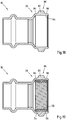
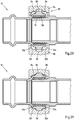
- Fig. 20 is the fitting 10 screwed onto a threaded connection 12 without already fully seal the connection between the fitting 10 and thread 12.
- the bead 82 is adapted to a circumferential recess 90 of a pressing contour of a pressing tool 92.
- This is a conventional pressing tool, in which two articulated pressing jaws 94 and 96 enclose the fitting 10, wherein the pressing jaws 94 and 96 in Fig. 20 only partially shown.
- the pressing jaws 94 and 96 have a pressing contour with the already mentioned recess 90, two adjoining cylindrical surfaces 98 and 100 and further adjoining polygonal elements 102 and 104.
- the polygonal elements 102 and 104 emboss when pressing a conventional press fitting a polygonal to a To ensure against rotation between the fitting and the pipe firmly connected.
- the recess 90 is used during pressing to deform a suitably configured bead with internal sealant such as an O-ring so that a tight connection between the fitting and pipe is formed. Since it is important when pressing on the most accurate deformation of the bead, the dimensions of the circumferential recess 90 are exactly predetermined.
- Fig. 20 the state before pressing is shown, in which the bead 82 is still spaced from the recess 90 is arranged. Other sections of the pressing surface 80 are not applied to the pressing contour of the pressing jaws 94 and 96.
- Fig. 21 now shows the state during the pressing or after pressing, in which the pressing jaws 94 and 96 still abut the fitting 10.
- the depression 90 abuts the bead 82 and has the bead 82 circumferentially pressed radially inward and thus permanently deformed.
- the cylindrical sections 84 and 86 of the fitting 10 not at the pressing jaw portions 98 and 100, so that in these areas no force and deformation of the fitting 10 has been caused.
- the polygonal elements 102 and 104 are not in contact with the pressing contour 80.
- only the portion of the bead 82 has been deformed inwardly and the radially inner portion of the sealing body 56 has been uniformly deformed so that a firm and lasting seal between the fitting 10 and the thread 12 has been achieved.
- Fig. 22 finally shows the finished compressed state of the fitting 10 with bead 82 without pressing tool.
- the configuration of the fitting 10 with the bead 82 has the advantage that only the recess 90 of the pressing jaws 94 and 96 are used for deforming the fitting 10.
- the dimensions of the recess 90 are specified for the conventional pressing tasks exactly, while the dimensions of the other sections of the pressing contour are not specified and set so accurate.
- an exact Pressten for the fitting 10 is achieved without the pressing tool must be adapted in a special way for the compression of the fitting 10 of the invention.
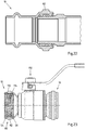
- Fig. 23 shows the previously explained fitting 10 according to the FIGS. 18 to 22 in a direct connection to a valve in the form of a ball valve 110, whose operation does not need to be explained in detail.
- the fitting 10 also has the previously described bead 82 of the pressing surface 80, so that a conduit or another fitting with an external thread can be connected to the fitting 10 or the ball valve 110 in the manner described above.
- the fitting 10 can be made by a metal forming, so the entire fitting of ball valve and pipe fittings or fittings is cheaper to manufacture.
- Fig. 23 shows, the ball valve 100 on both sides of a fitting 10 according to the invention.
- the ball valve 110 has only one side of a fitting 10 according to the invention and on the other side a normal press fitting.
- the inner contour of the recess 54 has two grooves 112 and 114 which, during the screwing of the internal thread, reinforce tilting of the material of the sealing body 56 in order to allow a better securing of the sealing body 56 relative to the recess 54 of the fitting.
Landscapes
- Engineering & Computer Science (AREA)
- General Engineering & Computer Science (AREA)
- Mechanical Engineering (AREA)
- Joints With Pressure Members (AREA)
Description
- Die Erfindung betrifft eine Verwendung eines Fittings für eine Anbindung an einem Gewindeanschluss einer Leitung, insbesondere einer Wasserleitung, oder an einer Armatur zur Verpressung mit einem Presswerkzeug, der Fitting umfassend einen Grundkörper, einen Gewindeabschnitt und einen am Gewindeabschnitt angeordneten Dichtkörper, wobei der Grundkörper an der dem Gewindeabschnitt gegenüberliegenden Seite eine Pressfläche aufweist, wobei der Dichtkörper eine zylindrische Grundform aufweist und sich axial mindestens entlang einer Windung, vorzugsweise mindestens entlang von zwei Windungen des abzudichtenden Gewindes des Gewindeanschlusses erstreckt und wobei der Dichtkörper zumindest teilweise mit einem Gewinde versehen ist. Die Erfindung betrifft auch ein Verfahren zum Anbinden eines Fittings an einem Gewindeanschluss einer Leitung.
- Bei der Neuinstallation oder der Instandsetzung von bestehenden Leitungen, insbesondere in der Hausinstallation von Trinkwasser- bzw. Heizungsleitungen, müssen regelmäßig Gewindeübergänge hergestellt werden. Üblicher Weise werden dabei kegelige Gewinde verwendet. Der Nenndurchmesser des konischen Gewindes entspricht nach einigen Umdrehungen dem des zylindrischen Gegengewindes. Bei weiterem Anziehen verklemmen sich die Gewinde ineinander und wirken so metallisch dichtend. Trotzdem werden solche Whitworth-Rohrgewinde oder "R-Gewinde" vor dem Verschrauben zusätzlich mit Dichtmitteln wie Teflon oder Hanf versehen, um die verbleibenden Spalte zu füllen, um eine sichere und dauerhafte Abdichtung zu gewährleisten.
- Diese Art der Installation ist zeitintensiv und durch die Verwendung von separatem Dichtmittel oder Dichtpaste hygienisch nicht immer einwandfrei. Außerdem werden die Dichtmittel regelmäßig per Hand ein- bzw. aufgebracht, wodurch Unregelmäßigkeiten in der Dichtung entstehen können. Des Weiteren werden bei der Herstellung der Verbindung mittels Werkzeugen, beispielsweise Schraubenschlüssel oder Rohrzange, teilweise hohe Drehmomente in die Verbindung eingeleitet. Somit können bei Herstellung der Schraubverbindung zwischen verschiedenen Komponenten und dem Rohrleitungssystem Beschädigungen an den Gewinden bzw. den Komponenten auftreten. Zudem sind Gewindeverbindungen nach deren Installation zeitaufwändig durch den Handwerker auf Dichtheit zu prüfen. Derartige Komponenten können beispielsweise Zu- und Abläufe von Warmwasserspeichern, Heizungskesseln, Armaturen, Filtern oder Ventilen sein.
- Grundsätzlich können die beschriebenen Fittings für Leitungen mit flüssigen oder gasförmigen Fluiden eingesetzt werden. Wenn im Folgenden die Erfindung anhand von Wasserleitungen beschrieben wird, ist dieses nicht beschränkend zu verstehen.
- In der
US 2,380,690 A wird eine Rohrkupplung offenbart. Ein Dichtelement aus einem weicheren Metall ist vorgesehen und weist ein Gewinde auf. - Die
US 2006/0208488 A1 betrifft eine Rohrkupplung für Öl- und Gasleitungen, wobei ein Rohr über eine Gewindeverbindung in ein weiteres Rohr geschraubt und einem radialen Aufweiten unterworfen wird. - In der
BE 884150 A - Die
EP 1 626 217 A1 offenbart eine Verbindung eines Fittings über ein Gewinde mit einem Anschlussstück. Der Fitting wird mit einem Presswerkzeug von innen punktuell verpresst. - In der
US 2004/0090068 A1 wird eine Rohrkupplung für eine Verbindung von Rohren über ein radiales Aufweiten offenbart. Die Rohre können dabei über Gewindeverbindungen mit der Rohrkupplung verschraubt werden. - Die
US 2,926,029 A beschreibt einen Fitting für eine Schlauchverbindung. - Die
WO 82/03901 A1 - Die
DE 10 2004 031 247 A1 beschreibt eine Armatur mit einem Anschlussteil, in welches ein Rohr eingesteckt werden kann und welches Profilierungen aufweist. - In der
WO 2006/115417 A1 wird eine Fixerhülse angegeben, welche ein mit einem Außengewinde versehenes Rohr fixieren kann. - Die
US 2,631,871 A beschreibt ein Dichtelement für Gewindeverbindungen. Ein Dichtkörper aus einem elastischen Material erstreckt sich hierbei entlang eines Abschnitts eines Gewindes. - Der vorliegenden Erfindung liegt das technische Problem zugrunde, das Anbinden eines Fittings an einem Gewindeanschluss einer Leitung oder einer Armatur zu vereinfachen und gleichzeitig zuverlässiger auszugestalten.
- Das zuvor aufgezeigte technische Problem wird durch eine Verwendung der eingangs genannten Art dadurch gelöst, dass der Grundkörper an der dem Gewindeabschnitt radial gegenüberliegenden Seite an der Pressfläche verpresst wird.
- Mit dem erfindungsgemäßen Fitting kann der Grundkörper im aufgeschraubten Zustand mit einem bereits bekannten Presswerkzeug verpresst werden. Der Dichtkörper wird durch das Verpressen des Grundkörpers im Bereich der Pressfläche an das Gewinde des Gewindeanschlusses und den Gewindeabschnitt des Fittings angepresst, wodurch eine zuverlässige Abdichtung des Fittings gegenüber dem Gewindeanschluss erreicht wird. Das Fitting weist dann am dem Gewindeabschnitt gegenüberliegenden Ende beispielsweise eine an sich bekannte Pressfittingkontur auf, um daran eine weitere Leitung anschließen zu können.
- Da die Abdichtung zwischen dem Fitting und dem Gewindeanschluss erst nach dem Verpressen erfolgt, kann das Gewinde des Gewindeabschnitts ohne besondere Krafteinleitung auf den Gewindeanschluss aufgeschraubt werden. Denn eine zuverlässige Abdichtung alleine durch das Aufschrauben ist nicht erforderlich. Das Verpressen des Fittings erfolgt dann hauptsächlich radial, wodurch die mit dem Gewindeanschluss verbundene Leitung nicht oder nur wenig belastet wird.
- Durch die Erfindung können beschädigte oder undichte Gewindeverbindungen vermieden, zeitintensive Arbeitsschritte eingespart, Folgeschäden durch fehlerhafte Verarbeitung vermieden und hygienisch unbedenkliche Dichtmittel, beispielsweise in Trinkwasserinstallationen angewendet werden. Gleichzeitig werden eine hohe Verdrehsicherheit, eine hohe Auszugsicherheit und eine hohe Dichtigkeit erreicht. Somit werden die Vorteile einer Schraubverbindung mit den Vorteilen einer Pressverbindung kombiniert.
- Die vorliegende Erfindung wird hauptsächlich für Whitworth-Rohrgewinde, sogenannte R-Gewinde, eingesetzt, ist aber nicht auf eine Anwendung bei konischen Gewinden beschränkt. Die Erfindung kann auch bei anderen Gewinden, beispielsweise zylindrischen Gewinden angewendet werden. Außerdem kann das beschriebene Fitting grundsätzlich für alle Gewindedurchmesser angewendet werden. Hauptsächliche Anwendung findet das Fitting jedoch bei den üblichen Gewindeanschlüssen im Hausinstallationsbereich, die im Bereich von 0,25 Zoll bis 1,5 Zoll liegen.
- Durch den Einsatz von vorgefertigten Fittings für Gewindeanschlüsse einschließlich einer werksseitig montierten Dichtung werden kurze Montagezeiten bei hoher Qualität der erzeugten Verbindung erreicht. Zudem stellt es einen Vorteil dar, wenn die Schraubverbindung im ersten Montageschritt noch nicht verpresst und somit noch ausgerichtet werden kann. Somit kann die Rohrverbindung zunächst vorinstalliert und ausgerichtet werden, um danach erst verpresst und somit fixiert zu werden.
- Der Grundkörper kann aus den bekannten Materialien Edelstahl, Stahl, Kupfer, Kupferlegierungen, anderen Metallen oder aus einem Kunststoff, wie beispielsweise Ethylen-Propylen-Dien-Monomer (EPDM), Hydrierter Acrylnitrilbutadien-Kautschuk (HNBR), Fluorkarbon-Kautschuk (FKM), Silicone, Polyurethan (PU) oder Chlor-Butyl hergestellt werden. Die Herstellung des Grundkörpers kann insbesondere durch Umformen erfolgen, so dass eine teure spanabhebende Bearbeitung vermieden werden kann. Der Dichtkörper kann aus einem Weichmetall, aus Kunststoff, insbesondere aus temperaturstabilen Kunststoffen wie Polytetrafluorethylen (PTFE), Polyethersulfone (PES), Polyarylsulfone (PPSU) oder auch nachträglich vernetzte Kunststoffe wie Polyethylen (PEX) oder aus vernetzten Elastomeren bestehen.
- Bei einer bevorzugten Ausgestaltung der vorliegenden Erfindung weist der Gewindeabschnitt ein Gewinde zumindest teilweise bestehend aus dem Material des Grundkörpers auf. Somit bildet der Grundkörper des Fittings mit seinem Gewindeabschnitt selbst zumindest einen Teil des Gewindes, das auf einen Gewindeanschluss einer Leitung aufgeschraubt wird. Der Dichtkörper wird dann im Gewindeabschnitt so angeordnet, dass nach dem Aufschrauben des Grundkörpers zumindest das Gewinde des Gewindeabschnitts selbst als auch gegebenenfalls der Dichtkörper mit dem Gewinde des Gewindeanschlusses in Kontakt stehen. Ebenso kann der Dichtkörper nur im Bereich des Gewindes des Gewindeanschlusses angeordnet sein, ohne mit diesem in Berührung zu stehen. Durch das Verpressen des Gewindeabschnitts wird dann der Dichtkörper in die Gewindegänge des Gewindeanschlusses eingepresst und es kommt zur gewünschten dauerhaften Abdichtung zwischen dem Fitting und dem Gewindeanschluss.
- Dazu ist es weiter bevorzugt, dass der Gewindeabschnitt eine umlaufende Nut zur Aufnahme des Dichtkörpers aufweist. Somit ist der Dichtkörper zu beiden Seiten von jeweils einem Teil des Gewindes des Gewindeabschnitts eingegrenzt. Der Dichtkörper hat somit eine definierte Position innerhalb des Gewindeabschnitts und gewinnt dadurch eine axiale Stabilität beim Aufschrauben des Fittings.
- Grundsätzlich kann der Dichtkörper in verschiedener Weise ausgebildet sein. Bevorzugt ist, dass der Dichtkörper schnurförmig ausgebildet ist und sich umfangseitig mindestens entlang einer Windung, vorzugsweise mindestens entlang von zwei Windungen des abzudichtenden Gewindes des Gewindeanschlusses erstreckt. Der schnurförmige Dichtkörper nimmt dabei vorzugsweise selber die Form einer Windung an, so dass der Dichtkörper während des Aufschraubens des Fittings auf den Gewindeanschluss in eine feste Anlage an dessen Gewinde kommt.
- Daneben kann der Dichtkörper eine zylindrische Grundform aufweisen und sich axial mindestens entlang einer Windung, vorzugsweise mindestens entlang von zwei Windungen des abzudichtenden Gewindes des Gewindeanschlusses erstrecken. Diese Ausgestaltung hat den Vorteil, dass der Dichtkörper eine größere axiale Stabilität aufweist. In dieser Form kann der Dichtkörper eine rein zylindrische Form aufweisen oder ebenfalls zumindest teilweise mit einem Gewinde versehen sein.
- In einer alternativen Ausgestaltung des erfindungsgemäßen Fittings kann der Gewindeabschnitt eine Vertiefung zur Aufnahme des Dichtkörpers aufweisen, wobei der Dichtkörper das Gewinde bildet. Durch die Vertiefung wird der Dichtkörper am Grundkörper gehalten und axial stabilisiert. Da der Dichtkörper selbst und nicht das Material des Grundkörpers das Gewinde bildet, ist es bevorzugt, dass der Dichtkörper gegenüber einer Drehung relativ zum Grundkörper gesichert ist. Beim Aufschrauben des Fittings kommt dann das Gewinde des Dichtkörpers mit dem Gewinde des Gewindeanschlusses in Eingriff, um nach dem Verpressen des Gewindeabschnitts eine zuverlässige dichte Verbindung zu bilden.
- Des Weiteren kann die Verbindung zwischen dem Gewinde des Gewindeabschnitts und dem Gewinde des Gewindeanschlusses im aufgeschraubten und unverpressten Zustand undicht sein. Dadurch wird bei der Montage des Leitungssystems bei Verwendung des zuvor beschriebenen Fittings sichergestellt, dass bei einer Belastungsprobe aus einem nicht verpressten Fitting das in der Leitung transportierte Wasser bzw. das zu transportierende Fluid austritt. Zur Sicherstellung der Undichtigkeit des unverpressten, aufgeschraubten Fittings kann beispielsweise im Gewinde des Gewindeabschnitts und/oder des Dichtkörpers eine axiale Nut bzw. eine axiale Ausweitung oder Einbuchtung vorgesehen sein, die erst nach dem Verpressen verschlossen wird. Dadurch sind unverpresste Gewindeverbindungen sicher undicht, wodurch der Aufwand zur Überprüfung der Dichtheit der Gewindeverbindung nach der Installation verringert wird.
- Das erfindungsgemäße Fitting sowie dessen zuvor erläuterte vorteilhafte Ausgestaltungen können sowohl für ein Innengewinde als auch ein Außengewinde angewendet werden. Dabei steht die Ausgestaltung als Innengewinde im Vordergrund, da die meisten Gewindeanschlüsse in der Hausinstallation ein Außengewinde aufweisen. Gleichwohl ist die Erfindung nicht auf Fittings beschränkt, die ein Innengewinde aufweisen.
- Diese Pressfläche des Grundkörpers kann zumindest teilweise umlaufend ausgebildet sein oder sich über den gesamten Umfang erstrecken Zudem ist die Pressfläche des Grundkörpers zumindest teilweise, vorzugsweise vollständig an die Presskontur eines zu verwendenden Presswerkzeugs angepasst. Die Wandstärke im Bereich des zu verpressenden Gewindeabschnitts ist dabei so eingestellt, dass das Verpressen zu dem notwendigen Verformen des Gewindeabschnitts und somit des Dichtkörpers führt. Somit kann ein bereits vorhandenes Presswerkzeug verwendet werden, das für das Herstellen von Pressverbindungen zwischen Fittings und Rohrleitungen vorgesehen ist.
- In bevorzugter Weise kann die Pressfläche des Grundkörpers eine im Wesentlichen zylindrische Kontur aufweisen. Damit wird eine einfach herzustellende Außenkontur der Pressfläche realisiert und einfache Presswerkzeuge mit einfacher zylindrischer oder zumindest teilweise zylindrischer Presskontur können eingesetzt werden.
- Bekannte Presswerkzeuge weisen des Weiteren eine Presskontur mit einer umlaufenden Vertiefung auf, die an eine einen Dichtring aufnehmende Sicke eines Fittings angepasst ist. An die Vertiefung schließen sich zu beiden Seiten zylindrische Abschnitte und an mindestens einem der beiden zylindrischen Abschnitte ein Mehrkantprofil an, vorzugsweise ein Sechskantprofil auf. Das erfindungsgemäße Fitting kann dann eine Pressfläche des Grundkörpers mit einer umlaufenden, vorzugsweise massiven Wulst aufweisen. Die Wulst wird dann mittels der umlaufenden Vertiefung des Presswerkzeugs verpresst, während die weiteren zylindrischen Abschnitte und Mehrkantabschnitte der Presskontur des Presswerkzeugs beim Verpressen vorzugsweise nicht mit der Pressfläche des Fittings in Berührung kommen. Somit wird eine bekannte Presskontur eines herkömmlichen Presswerkzeugs eingesetzt, dessen Abmaße und Dimensionen der Vertiefung exakt vorgegeben sind und für ein exaktes Verpressen des aufgeschraubten Fittings eingesetzt werden können.
- Das oben aufgezeigte technische Problem wird auch durch ein Verfahren zum Anbinden eines Fittings an einem Gewindeanschluss einer Leitung, insbesondere einer Wasserleitung, oder an einer Armatur gelöst, bei dem eine Schraubverbindung zwischen einem Gewindeabschnitt des Fittings und dem Gewinde des Gewindeanschlusses hergestellt wird, wobei der Dichtkörper eine zylindrische Grundform aufweist und sich axial mindestens entlang einer Windung, vorzugsweise mindestens entlang von zwei Windungen des abzudichtenden Gewindes des Gewindeanschlusses erstreckt und der Dichtkörper zumindest teilweise mit einem Gewinde versehen ist, bei dem ein am Gewindeabschnitt angeordneter Dichtkörper zumindest teilweise im Bereich des Gewindes des Gewindeanschlusses positioniert wird und bei dem der Grundkörper an der dem Gewindeabschnitt radial gegenüberliegenden Seite des Grundkörpers an einer Pressfläche verpresst wird.
- Somit kann der Grundkörper im aufgeschraubten Zustand verpresst und der Dichtkörper an das Gewinde des Gewindeanschlusses sowie an den Gewindeabschnitt angepresst werden, wie zuvor schon anhand des Fittings erläutert worden ist.
- Durch das erfindungsgemäße Verfahren wird die Handhabung durch den Handwerker vereinfacht, denn das Fitting kann ohne Kraftaufwand auf den Gewindeanschluss aufgeschraubt werden, ohne dass es bereits zu einer festen Abdichtung kommt. Erst nach dem anschließenden Verpressen durch das Einbringen einer vorwiegend radialen Presskraft wird eine feste und dichte Verbindung erzeugt. Dabei wird keine zu große Torsionskraft durch ein festes Aufschrauben in die Verbindung eingebracht.
- Bei einer ersten Ausgestaltung des erfindungsgemäßen Verfahrens ist das Gewinde des Gewindeabschnitts ein Innengewinde und der Gewindeabschnitt wird mit einer Presszange radial nach innen verpresst. Dazu können bereits bekannte handelsübliche Presswerkzeuge bzw. Presszangen eingesetzt werden. Die Außenkontur des Gewindeabschnitts, die die Pressfläche bildet, wird dazu an die Presskontur des Presswerkzeugs angepasst, um eine besondere Ausgestaltung des Presswerkzeugs zu vermeiden.
- Bei einer zweiten Ausgestaltung des erfindungsgemäßen Verfahrens ist das Gewinde des Gewindeabschnitts ein Außengewinde und der Gewindeabschnitt wird mit einem Aufweitungswerkzeug radial nach außen verpresst. Dazu kann das Fitting mit eingesetztem Aufweitungswerkzeug bestehend aus einer Aufweitungshülse und einem Aufweitungsstempel aufgeschraubt werden. Anschließend wird die Aufweitungshülse durch Herausziehen des Aufweitungsstempels nach außen aufgeweitet, um dabei den Gewindeabschnitt nach außen aufzuweiten. Dadurch wird der Dichtkörper zuverlässig abdichtend mit dem Innengewinde des Gewindeanschlusses und dem Gewindeabschnitt des Fittings verpresst.
- Im Folgenden wird die Erfindung anhand von Ausführungsbeispielen näher erläutert, wozu auf die beigefügte Zeichnung Bezug genommen wird. In der Zeichnung zeigen
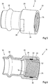
- Fig. 1
- ein erstes Ausführungsbeispiel eines erfindungsgemäßen Fittings mit einem Gewindeabschnitt mit Innengewinde in einer perspektivischen Darstellung,
- Fig. 2
- das Fitting aus
Fig.1 in einer geschnittenen perspektivischen Darstellung, - Fig. 3
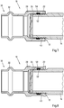
- das Fitting aus
Fig. 1 aufgeschraubt auf einen Gewindeanschluss im unverpressten Zustand im Querschnitt, - Fig. 4
- das Fitting aus
Fig.1 aufgeschraubt auf einen Gewindeanschluss im verpressten Zustand im Querschnitt, - Fig. 5
- ein zweites Ausführungsbeispiel eines erfindungsgemäßen Fittings mit einem Gewindeabschnitt mit Innengewinde in einer perspektivischen Darstellung,
- Fig. 6
- das Fitting aus
Fig. 5 in einer geschnittenen perspektivischen Darstellung, - Fig. 7
- das Fitting aus
Fig. 5 aufgeschraubt auf einen Gewindeanschluss im unverpressten Zustand im Querschnitt, - Fig. 8
- das Fitting aus
Fig. 5 aufgeschraubt auf einen Gewindeanschluss im verpressten Zustand im Querschnitt, - Fig. 9
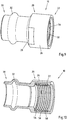
- ein drittes Ausführungsbeispiel eines erfindungsgemäßen Fittings mit einem Gewindeabschnitt mit Innengewinde in einer perspektivischen Darstellung,
- Fig. 10
- das Fitting aus
Fig. 9 in einer geschnittenen perspektivischen Darstellung, - Fig. 11
- das Fitting aus
Fig. 9 aufgeschraubt auf einen Gewindeanschluss im unverpressten Zustand im Querschnitt, - Fig. 12
- das Fitting aus
Fig. 9 aufgeschraubt auf einen Gewindeanschluss im verpressten Zustand im Querschnitt, - Fig. 13
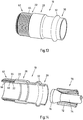
- ein viertes Ausführungsbeispiel eines erfindungsgemäßen Fittings mit einem Gewindeabschnitt mit Außengewinde in einer perspektivischen Darstellung,
- Fig. 14
- das Fitting aus
Fig. 13 mit Aufweitungswerkzeug in einer perspektivischen Darstellung, - Fig. 15
- das Fitting aus
Fig. 13 aufgeschraubt auf einen Gewindeanschluss im unverpressten Zustand im Querschnitt, - Fig. 16
- das Fitting aus
Fig. 13 aufgeschraubt auf einen Gewindeanschluss im teilweise verpressten Zustand während des Herausziehens des Aufweitungswerkzeugs im Querschnitt, - Fig. 17
- das Fitting aus
Fig. 13 aufgeschraubt auf einen Gewindeanschluss im verpressten Zustand, - Fig. 18
- ein fünftes Ausführungsbeispiel eines erfindungsgemäßen Fittings mit einem Gewindeabschnitt mit Innengewinde im Querschnitt mit einer gegenüber dem dritten Ausführungsbeispiel geänderten Außenkontur der Pressfläche des Grundkörpers,
- Fig. 19
- das Fitting aus
Fig. 18 mit eingesetztem Dichtkörper, - Fig. 20
- das Fitting aus
Fig. 19 aufgeschraubt auf einen Gewindeanschluss im unverpressten Zustand im Querschnitt mit angesetztem Presswerkzeug, - Fig. 21
- das Fitting aus
Fig. 19 aufgeschraubt auf einen Gewindeanschluss im verpressten Zustand im Querschnitt mit angesetztem Presswerkzeug, - Fig. 22
- das Fitting aus
Fig. 19 aufgeschraubt auf einen Gewindeanschluss im verpressten Zustand im Querschnitt und - Fig. 23
- das Fitting aus den
Fig. 19 bis 22 in einer direkten Anbindung an eine Armatur in Form eines Kugelventils. - Die
Fig. 1 bis 4 zeigen ein erstes Ausführungsbeispiel eines erfindungsgemäßen Fittings 10 für eine Anbindung an einem Gewindeanschluss 12 einer Leitung 14, die insbesondere eine Wasserleitung sein kann. - Wie
Fig.1 und 2 zeigen, weist das Fitting 10 einen Grundkörper 20, einen Gewindeabschnitt 22 und einen am Gewindeabschnitt 22 angeordneten Dichtkörper 24 auf. Zudem weist der Grundkörper 20 an der dem Gewindeabschnitt 22 radial gegenüberliegenden Seite eine Pressfläche 26 auf. Die Pressfläche 26 ist zylindrisch ausgebildet. Der Grundkörper 20 weist darüber hinaus abgeflachte Abschnitte 28 für den Ansatz von Schraubschlüsseln beim Aufschrauben des Fittings 10 auf. - Das Fitting 10 weist am dem Gewindeabschnitt 20 gegenüberliegenden Endabschnitt 30 eine herkömmliche Wulst 32 für die Aufnahme eines ringförmigen Dichtmittels auf. Der Endabschnitt 30 kann also für eine herkömmliche Pressverbindung mit einem Anschlussrohr verwendet werden. Die genaue Ausgestaltung des Pressfittings am Endabschnitt 30 ist für die vorliegende Erfindung nicht wesentlich. Das Fitting 10 kann auch anstelle einer weiteren Pressverbindung direkt einstückig in ein Leitungsrohr mit einer vorgegebenen Länge oder in eine Armatur, Ventilanordnung oder Abzweigung in Form eines T-Stücks oder Kreuzungsstücks übergehen.
-
Fig. 1 und 2 zeigen, dass der Gewindeabschnitt 22 ein Gewinde 34 bestehend aus dem Material des Grundkörpers 20 aufweist. Das Gewinde 34 dient zum Aufschrauben auf den Gewindeanschluss 12. Des Weiteren weist der Gewindeabschnitt 22 eine umlaufende Nut 36 zur Aufnahme des Dichtkörpers 24 auf. Der Dichtkörper 24 ist schnurförmig ausgebildet und erstreckt sich umfangseitig entlang von zwei Windungen des abzudichtenden Gewindes 40 des Gewindeanschlusses 12. -
Fig. 3 zeigt den Fitting 10 nach dem Aufschrauben auf dem Gewindeanschluss 12 im unverpressten Zustand. Das Außengewinde 40 des Gewindeanschlusses 12 steht im teilweisen Eingriff sowohl mit dem Gewinde 34 als auch mit dem Dichtkörper 24. In diesem Zustand ist die Verbindung zwischen dem Fitting 10 und dem Gewindeanschluss 12 noch nicht sicher abgedichtet. Im dargestellten aufgeschraubten Zustand weisen die beiden Gewinde 34 und 40 noch einen geringen Abstand voneinander auf, was an einer größeren Strichstärke inFig. 3 zu erkennen ist. Anschließend wird das Fitting an der Pressfläche 26 radial nach innen verpresst und der Dichtkörper 24 wird somit an das Gewinde 40 des Gewindeanschlusses 12 angepresst. - Der Zustand nach dem Verpressen wird in
Fig. 4 dargestellt, wobei die geänderte Form des Gewindeabschnitts 22 zu erkennen ist. Die beiden Gewinde 34 und 40 liegen eng aneinander an. Somit wird erst durch das radial nach innen verlaufende Verpressen eine dauerhafte dichte Verbindung zwischen dem Fitting 10 und dem Gewindeanschluss 12 fertig gestellt. - In den
Fig. 5 bis 8 wird ein zweites Ausführungsbeispiel der vorliegenden Erfindung dargestellt. Dabei kennzeichnen gleiche Bezugszeichen gleiche Elemente, wie sie schon anhand derFig. 1 bis 4 beschrieben worden sind. - Beim vorliegenden Ausführungsbeispiel weist der Dichtkörper 50 eine zylindrische Grundform auf und erstreckt sich axial entlang von zwei Windungen des abzudichtenden Gewindes 40 des Gewindeanschlusses 12. Dabei ist der Dichtkörper 50 in der Nut 36 angeordnet, die bereits anhand der
Fig.1 und 2 beschrieben worden ist. - Wie in den
Fig. 5 und 6 dargestellt ist, ist der Dichtkörper 50 mit einem Gewinde 52 versehen, das zusätzlich zu dem Gewinde 34 des Gewindeabschnittes 22 zum Aufschrauben auf den Gewindeanschluss 12 aufgeschraubt wird. Somit kommt der Dichtkörper 50 bereits während des Aufschraubens in direkten Kontakt mit den Windungen des Gewindes 40, wie inFig. 7 gezeigt ist.Fig. 8 zeigt dann wieder den verpressten Zustand des Fittings. - Wie sich aus den
Fig. 2 und6 ergibt, weisen die Dichtkörper 24 und 50 einen größeren Innendurchmesser als das Gewinde 34 des Gewindeabschnittes 22 auf. Somit wird der jeweilige Dichtkörper 24, 50 während des Aufschraubens nicht stark belastet und die Last der aufzubringenden Schraubkraft wird vom Gewinde 34 getragen. Dadurch wird unter anderem vermieden, dass sich der Dichtkörper 24, 50 beim Aufschrauben verkantet oder in anderer Weise aus seiner vorgegebenen Position heraus bewegt. Gleichwohl kommt der Dichtkörper 24, 50 in Berührung, Anlage oder teilweisem Eingriff mit dem Gewinde 40 des Gewindeanschlusses 12. - In den
Fig. 9 bis 12 wird ein drittes Ausführungsbeispiel der vorliegenden Erfindung dargestellt. Dabei kennzeichnen gleiche Bezugszeichen gleiche Elemente, wie sie schon anhand derFig. 1 bis 4 beschrieben worden sind. - Wie
Fig. 9 und 10 zeigen, weist der Gewindeabschnitt 22 eine Vertiefung 54 zur Aufnahme des Dichtkörpers 56 auf. Daher weist der Gewindeabschnitt 22 des Grundkörpers 20 nicht das Gewinde zum Aufschrauben auf den Gewindeanschluss 12 auf, sondern der Dichtkörper 56 selbst weist ein Gewinde 58 auf. Allein dieses Gewinde 58 wird für das Aufschrauben auf den Gewindeanschluss 12 verwendet. - Ein besonderer Vorteil dieser Ausgestaltung ohne Gewinde im Gewindeabschnitt 22 des Grundkörpers 20 besteht darin, dass der Grundkörper 20 durch Metallumformen hergestellt werden kann, wodurch sich im Gegensatz zu einem spanabhebenden Verfahren zur Herstellung eines metallischen Gewindes eine deutliche Kosteneinsparung erzielen lässt.
-
Fig.11 zeigt wieder den aufgeschraubten aber unverpressten Zustand, währendFig. 12 den Zustand nach dem Verpressen zeigt. - Die Ausführungsbeispiele nach den
Fig. 1 bis 12 sind so ausgebildet, dass das Gewinde 34, 52 bzw. 58 des Gewindeabschnitts 2 ein Innengewinde ist und dass daher der Gewindeabschnitt 22 mit einer Presszange radial nach innen verpresst werden kann. - In dieser Weise wird der Übergang vom unverpressten in den verpressten Zustand von den
Fig. 3 nach 4, 7 nach 8 und 11 nach 12 erreicht. - Das Ausführungsbeispiel nach den
Fig. 13 bis 17 weist einen Fitting 10 für einen Gewindeanschluss 12 auf, wobei der Gewindeanschluss 12 mit einem Innengewinde 42 versehen ist. Dabei kennzeichnen wieder gleiche Bezugszeichen gleiche Elemente, wie sie schon anhand derFig.1 bis 4 beschrieben worden sind. - Der Grundkörper 20 des Fittings 10 weist einen Gewindeabschnitt 22 mit einer Außenkontur mit einer umlaufenden Vertiefung 60 und einer im Wesentlichen zylindrischen Innenkontur auf. In der Vertiefung ist der Dichtkörper 62 mit im Wesentlichen zylindrischer Form positioniert, der an der Außenseite mit einem Gewinde 64 versehen ist. Das Fitting 10 wird in das Außengewinde 42 des Gewindeanschlusses eingeschraubt, so dass der Dichtkörper 62 im Bereich des Gewindes 42 positioniert wird. Der Dichtkörper 62 ist also in ähnlicher Weise wie der Dichtkörper 56 nach den
Fig. 9 bis 12 ausgebildet. Es ist aber ebenso möglich, den Dichtköper und auch den Gewindeabschnitt in ähnlicher Weise wie nach denFig. 1 bis 8 auszugestalten. - Anschließend erfolgt das Verpressen des Gewindeabschnitts 22 an einer Pressfläche 66 durch eine Aufweitung im Wesentlichen radial nach außen, so dass eine sichere Abdichtung zwischen dem Fitting 10 und dem Gewindeanschluss 12 erreicht wird. Dieser Vorgang wird weiter unten anhand der
Fig. 15 bis 17 näher erläutert. - Die zuvor erläuterten Ausführungsbeispiele des erfindungsgemäßen Fittings können so ausgestaltet werden, dass die Verbindung zwischen dem Gewinde 34, 52, 58; 64 des Gewindeabschnitts 22 und dem Gewinde 40; 42 des Gewindeabschnitts 12 im aufgeschraubten und unverpressten Zustand undicht ist. Dazu kann eine axiale Nut bzw. axiale Ausweitung im Gewinde 34, 52,58; 64 vorgesehen sein. Diese ist nicht explizit in den Figuren dargestellt. Die axiale Nut bzw. axiale Ausweitung wird erst durch das Verpressen abdichtend verformt, während vor dem Verpressen ein absichtliches Leck vorhanden ist, das bei einer Funktionsprüfung durch Austritt des Wassers aus der Verbindung detektiert werden kann.
- Das erfindungsgemäße Verfahren zum Anbinden eines Fittings 10 an einem Gewindeanschluss 12 einer Leitung 14 weist, wie anhand der
Figuren 1 bis 16 beschrieben die folgenden Schritte auf: - Auf- bzw. Einschrauben des Fittings 10 mit einem Gewindeabschnitt 22 auf bzw. in das Gewinde 40 des Gewindeanschlusses 12 zum Herstellen einer Schraubverbindung,
- Positionieren eines am Gewindeabschnitt 22 angeordneter Dichtkörper 24, 50, 56; 62 zumindest teilweise im Bereich des Gewindes 40; 42 des Gewindeanschlusses 12 und
- Verpressen des Grundkörpers 20 an der dem Gewindeabschnitt 22 radial gegenüberliegenden Seite an einer Pressfläche 26,66 insbesondere in radialer Richtung.
- Wenn das Gewinde 40 des Gewindeabschnitts 22 ein Innengewinde ist, wird der Gewindeabschnitt 22 mit einer Presszange radial nach innen verpresst. Dieses ist bereits oben anhand der
Fig. 1 bis 12 erläutert worden. - Ist dagegen das Gewinde 42 des Gewindeabschnitts 22 ein Außengewinde, wird der Gewindeabschnitt 22 mit einem Aufweitungswerkzeug 70 radial nach außen verpresst, wie in den
Fig. 13 bis 17 dargestellt wird. - Wie
Fig. 15 zeigt, wird vor dem Einschrauben des Fittings 10 in das Gewinde 42 das Aufweitungswerkzeug 70 bestehend aus einer Aufweitungshülse 72 und einem Stempel 74 mit einem aufgeweiteten Ende 76 durch das Fitting 10 hindurch geschoben. Danach wird das Fitting 10 zusammen mit dem Aufweitungswerkzeug 70 in das Gewinde 42 eingeschraubt, bis der Dichtkörper 62 im Bereich des Gewindes 42 angeordnet ist. GemäßFig. 16 wird anschließend der Stempel 74 aus dem Fitting 10 und aus der darin lösbar befestigten Aufweitungshülse 72 herausgezogen. Dabei durchläuft das aufgeweitete Ende 76 den Gewindeabschnitt 22 entlang der Pressfläche 66 und drückt den Gewindeabschnitt 22 radial nach außen. Dadurch wird der Dichtkörper 62 fest mit dem Gewinde 42 verpresst und eine sicher und dichte Verbindung zwischen dem Fitting 10 und dem Gewindeanschluss 12 wird hergestellt, wie inFig. 17 dargestellt ist. - Wie sich aus der Beschreibung der
Fig.1 bis 17 ergibt, weist die Pressfläche 26; 66 des Grundkörpers 20 eine im Wesentlichen zylindrische Kontur auf. Somit können radial nach innen wirkende Presswerkzeuge, beispielsweise Presszangen, mit einer Presskontur eingesetzt werden, die mindestens einen Abschnitt aufweist, der mit der zylindrischen Kontur der Pressfläche 26 in Eingriff gebracht werden kann. Dabei kann der zylindrische Abschnitt der Presskontur ein Teil einer komplexeren Presskontur sein. Es kommt dabei nur darauf an, dass die Pressfläche 26 an das zu benutzende Werkzeug so angepasst ist, dass diese unverändert ein erfolgreiches Verpresssen des Fittings 10 ermöglicht. - Die
Fig. 18 bis 22 zeigen ein fünftes Ausführungsbeispiel eines erfindungsgemäßen Fittings 10, der in Bezug auf die Anordnung der Vertiefung 54 und des Dichtkörpers 56 mit Innengewinde 58 gleich ist wie das dritte Ausführungsbeispiel nach denFig. 9 bis 12 . - Das fünfte Ausführungsbeispiel weist nun eine von der zylindrischen Pressfläche des dritten Ausführungsbeispiels abweichende Pressfläche 80 auf, die nachfolgend erläutert wird und ebenfalls bei allen Ausführungsbeispielen nach den
Fig. 1 bis 12 anstelle der zylindrischen Pressfläche 26 angewendet werden kann. - Beim fünften Ausführungsbeispiel weist die Pressfläche 80 des Grundkörpers 20 eine umlaufende, massive Wulst 82 auf. Die Wulst 82 ist insbesondere in den
Fig. 18 und 19 zu erkennen, wobei inFig. 18 der Dichtkörper 56 weggelassen worden ist, währendFig. 19 den in der Vertiefung 54 eingesetzten Dichtkörper 56 mit Innengewinde 58 zeigt. Zu beiden Seiten der Wulst 82 schließen sich im Wesentlichen zylindrische Flächen 84 und 86 an. - In
Fig. 20 ist der Fitting 10 auf einen auf den Gewindeanschluss 12 aufgeschraubt, ohne bereits vollständig die Verbindung zwischen Fitting 10 und Gewinde 12 abzudichten. Zudem ist die Wulst 82 an eine umlaufende Vertiefung 90 einer Presskontur eines Presswerkzeugs 92 angepasst. Dabei handelt es sich um ein herkömmliches Presswerkzeug, bei dem zwei gelenkig gelagerte Pressbacken 94 und 96 den Fitting 10 umschließen, wobei die Pressbacken 94 und 96 inFig. 20 nur teilweise dargestellt sind. - Die Pressbacken 94 und 96 weisen eine Presskontur mit der bereits erwähnten Vertiefung 90, zwei sich daran anschließenden zylindrischen Flächen 98 und 100 und weiterhin sich anschließende Mehrkantelemente 102 und 104. Die Mehrkantelemente 102 und 104 prägen beim Verpressen eines herkömmlichen Pressfittings einen Mehrkant ein, um eine Verdrehsicherung zwischen dem Fitting und dem damit fest verbundenen Rohr zu gewährleisten. Die Vertiefung 90 dient beim Verpressen dazu, eine entsprechend ausgestaltete Sicke mit innen liegendem Dichtmittel wie beispielsweise einem O-Ring so zu verformen, dass eine dichte Verbindung zwischen Fitting und Rohr entsteht. Da es beim Verpressen auf eine möglichst exakte Verformung der Sicke ankommt, sind die Dimensionen der umlaufenden Vertiefung 90 exakt vorgegeben.
- In
Fig. 20 ist der Zustand vor dem Verpressen dargestellt, in dem der Wulst 82 noch beabstandet von der Vertiefung 90 angeordnet ist. Auch andere Abschnitte der Pressfläche 80 liegen nicht an der Presskontur der Pressbacken 94 und 96 an. -
Fig. 21 zeigt nun den Zustand während des Verpressens bzw. nach dem Verpressen, in dem die Pressbacken 94 und 96 noch am Fitting 10 anliegen. In diesem Zustand liegt die Vertiefung 90 am Wulst 82 an und hat den Wulst 82 umlaufend radial nach innen verpresst und somit dauerhaft verformt. Dagegen liegen die zylindrischen Abschnitte 84 und 86 des Fittings 10 nicht an den Pressbackenabschnitten 98 und 100 an, so dass in diesen Bereichen keine Krafteinwirkung und Verformung des Fittings 10 hervorgerufen worden ist. Ebenso liegen die Mehrkantelemente 102 und 104 nicht an der Presskontur 80 an. Somit wurde nur der Bereich der Wulst 82 nach innen verformt und der radial innen liegende Abschnitt des Dichtkörpers 56 wurde gleichmäßig verformt, so dass eine feste und dauerhafte Abdichtung zwischen dem Fitting 10 und dem Gewinde 12 erreicht worden ist. -
Fig. 22 zeigt schließlich den fertig verpressten Zustand des Fittings 10 mit Wulst 82 ohne Presswerkzeug. - Die Ausgestaltung des Fittings 10 mit der Wulst 82 hat den Vorteil, dass nur die Vertiefung 90 der Pressbacken 94 und 96 für das Verformen des Fittings 10 verwendet werden. Die Abmessungen der Vertiefung 90 sind für die herkömmlichen Pressaufgaben exakt vorgegeben, während die Abmessungen der anderen Abschnitte der Presskontur nicht so genau vorgegeben und eingestellt sind. Somit wird ein exaktes Pressergebnis für den Fitting 10 erreicht, ohne dass das Presswerkzeug in besonderer Weise für das Verpressen des erfindungsgemäßen Fittings 10 angepasst werden muss.
-
Fig. 23 zeigt das zuvor erläuterte Fitting 10 gemäß denFig. 18 bis 22 in einer direkten Anbindung an eine Armatur in Form eines Kugelventils 110, dessen Funktionsweise nicht im Detail erläutert werden braucht. Das Fitting 10 weist ebenfalls die zuvor beschriebene Wulst 82 der Pressfläche 80 auf, so dass eine Leitung oder eine weitere Armatur mit einem Außengewinde in der zuvor beschriebenen Weise mit dem Fitting 10 bzw. dem Kugelventil 110 verbunden werden kann. - Auch in diesem Ausführungsbeispiel kann das Fitting 10 durch eine Metallumformung hergestellt werden, so die gesamte Armatur aus Kugelventil und Leitungsanschlüssen bzw. Fittingen preiswerter in der Herstellung ist.
- Wie
Fig. 23 zeigt, weist das Kugelventil 100 zu beiden Seiten einen erfindungsgemäßen Fitting 10 auf. Daneben ist es auch möglich, dass das Kugelventil 110 nur auf einer Seite einen erfindungsgemäßen Fitting 10 und an der anderen Seite einen normalen Pressfitting aufweist. - Zusätzlich zu der Ausgestaltung nach den
Fig. 18 bis 22 weist die Innenkontur der Vertiefung 54 zwei Nuten 112 und 114 auf, die während des Einschraubens des Innengewindes ein Verkanten des Materials des Dichtkörpers 56 verstärkt, um eine bessere Verdrehsicherung des Dichtkörpers 56 relativ zur Vertiefung 54 des Fittings zu ermöglichen.
Claims (13)
- Verwendung eines Fittings für eine Anbindung an einem Gewindeanschluss einer Leitung, insbesondere einer Wasserleitung, oder an einer Armatur zu einer Verpressung mit einem Presswerkzeug, der Fitting umfassend:- einen Grundkörper (20),- einen Gewindeabschnitt (22) und- einen am Gewindeabschnitt (22) angeordneten Dichtkörper (24, 50, 56; 62),- wobei der Grundkörper (20) an der dem Gewindeabschnitt (22) gegenüberliegenden Seite eine Pressfläche (26,66, 80) aufweist,- wobei der Dichtkörper (50) eine zylindrische Grundform aufweist und sich axial mindestens entlang einer Windung, vorzugsweise mindestens entlang von zwei Windungen des abzudichtenden Gewindes des Gewindeanschlusses erstreckt und- wobei der Dichtkörper (50) zumindest teilweise mit einem Gewinde (52) versehen ist,
dadurch gekennzeichnet,- dass der Grundkörper an der dem Gewindeabschnitt radial gegenüberliegenden Seite an der Pressfläche verpresst wird. - Verwendung nach Anspruch 1,
dadurch gekennzeichnet,
dass der Gewindeabschnitt (22) ein Gewinde (34) zumindest teilweise bestehend aus dem Material des Grundkörpers (20) aufweist. - Verwendung nach Anspruch 2,
dadurch gekennzeichnet,
dass der Gewindeabschnitt (22) eine umlaufende Nut (36) zur Aufnahme des Dichtkörpers (24, 50, 56) aufweist. - Verwendung nach Anspruch 3,
dadurch gekennzeichnet,
dass der Gewindeabschnitt (22) eine Vertiefung (54) zur Aufnahme des Dichtkörpers (56) aufweist und dass der Dichtkörper (56) ein Gewinde (58) bildet. - Verwendung nach einem der Ansprüche 1 bis 4,
dadurch gekennzeichnet,
die Verbindung zwischen dem Gewinde (34, 52, 58; 64) des Gewindeabschnitts (22) und dem Gewinde (40; 42) des Gewindeabschnitts (12) im aufgeschraubten und unverpressten Zustand undicht ist. - Verwendung nach einem der Ansprüche 1 bis 5,
dadurch gekennzeichnet,
dass das Gewinde (34, 52, 58) ein Innengewinde ist. - Verwendung nach einem der Ansprüche 1 bis 5,
dadurch gekennzeichnet,
dass das Gewinde (64) ein Außengewinde ist. - Verwendung nach einem der Ansprüche 1 bis 6,
dadurch gekennzeichnet,
dass die Pressfläche (26, 66) des Grundkörpers (20) eine im Wesentlichen zylindrische Kontur aufweist. - Verwendung nach einem der Ansprüche 1 bis 6,
dadurch gekennzeichnet,
dass die Pressfläche (80) des Grundkörpers (20) eine umlaufende, vorzugsweise massive Wulst (82) aufweist. - Verwendung nach Anspruch 9,
dadurch gekennzeichnet,
dass die Wulst (82) an eine umlaufende Vertiefung einer Presskontur eines Presswerkzeugs angepasst ist. - Verfahren zum Anbinden eines Fittings an einem Gewindeanschluss einer Leitung, insbesondere einer Wasserleitung, oder an einer Armatur,- bei dem eine Schraubverbindung zwischen einem Gewindeabschnitt des Fittings und dem Gewinde des Gewindeanschlusses hergestellt wird, wobei der Dichtkörper eine zylindrische Grundform aufweist und sich axial mindestens entlang einer Windung, vorzugsweise mindestens entlang von zwei Windungen des abzudichtenden Gewindes des Gewindeanschlusses erstreckt und der Dichtkörper zumindest teilweise mit einem Gewinde versehen ist,- bei dem ein am Gewindeabschnitt angeordneter Dichtkörper zumindest teilweise im Bereich des Gewindes des Gewindeanschlusses positioniert wird und- bei dem der Grundkörper an der dem Gewindeabschnitt radial gegenüberliegenden Seite an einer Pressfläche verpresst wird.
- Verfahren nach Anspruch 11,- bei dem das Gewinde des Gewindeabschnitts ein Innengewinde ist und- bei dem der Gewindeabschnitt mit einer Presszange radial nach innen verpresst wird.
- Verfahren nach Anspruch 11,- bei dem das Gewinde des Gewindeabschnitts ein Außengewinde ist und- bei dem der Gewindeabschnitt mit einem Aufweitungswerkzeug radial nach außen verpresst wird.
Priority Applications (1)
| Application Number | Priority Date | Filing Date | Title |
|---|---|---|---|
| PL14748131T PL3027948T3 (pl) | 2013-07-31 | 2014-06-30 | Złączka rurowa zaciskana do przyłącza gwintowego i sposób łączenia złączki rurowej z przyłączem gwintowym |
Applications Claiming Priority (2)
| Application Number | Priority Date | Filing Date | Title |
|---|---|---|---|
| DE102013108201.7A DE102013108201A1 (de) | 2013-07-31 | 2013-07-31 | Pressfitting für Gewindeanschluss |
| PCT/EP2014/063837 WO2015014557A1 (de) | 2013-07-31 | 2014-06-30 | Pressfitting für gewindeanschluss und verfahren zum anbinden eines fittings an einem gewindeanschluss |
Publications (2)
| Publication Number | Publication Date |
|---|---|
| EP3027948A1 EP3027948A1 (de) | 2016-06-08 |
| EP3027948B1 true EP3027948B1 (de) | 2017-10-04 |
Family
ID=51162677
Family Applications (1)
| Application Number | Title | Priority Date | Filing Date |
|---|---|---|---|
| EP14748131.1A Active EP3027948B1 (de) | 2013-07-31 | 2014-06-30 | Pressfitting für gewindeanschluss und verfahren zum anbinden eines fittings an einem gewindeanschluss |
Country Status (10)
| Country | Link |
|---|---|
| US (1) | US10359132B2 (de) |
| EP (1) | EP3027948B1 (de) |
| CN (1) | CN105659017B (de) |
| AU (1) | AU2014298821B2 (de) |
| DE (1) | DE102013108201A1 (de) |
| DK (1) | DK3027948T3 (de) |
| ES (1) | ES2644915T3 (de) |
| PL (1) | PL3027948T3 (de) |
| RU (1) | RU2659946C2 (de) |
| WO (1) | WO2015014557A1 (de) |
Cited By (1)
| Publication number | Priority date | Publication date | Assignee | Title |
|---|---|---|---|---|
| EP4703616A1 (de) * | 2024-08-28 | 2026-03-04 | Mueller Industries, Inc. | Fitting |
Families Citing this family (17)
| Publication number | Priority date | Publication date | Assignee | Title |
|---|---|---|---|---|
| USD788886S1 (en) * | 2016-05-24 | 2017-06-06 | Ray Salzer | Plumbing fitting |
| GB2551827A (en) * | 2016-06-30 | 2018-01-03 | Churchill Drilling Tools Ltd | Downhole coupling |
| CN106065977A (zh) * | 2016-08-06 | 2016-11-02 | 谢秋鸿 | 一种流体结构的密封装置 |
| US11154936B2 (en) * | 2016-09-29 | 2021-10-26 | Kyocera Corporation | Cutting tool and method of manufacturing machined product using them |
| IT201600120936A1 (it) * | 2016-11-29 | 2018-05-29 | Giacomini Spa | Giunzione per tubazioni metalliche |
| USD828399S1 (en) * | 2017-02-27 | 2018-09-11 | Chandler Fitzgerald | Throttle body coupler |
| CN106969218B (zh) * | 2017-05-11 | 2017-12-26 | 黄德修 | 一种改进的钳压式管件 |
| US11398719B2 (en) | 2019-04-30 | 2022-07-26 | Eaton Intelligent Power Limited | Press fit condulet devices, assemblies systems and methods for electrical raceway fabrication |
| US11320069B2 (en) * | 2019-07-22 | 2022-05-03 | Parker-Hannifin Corporation | Threaded coupling with under-torque prevention |
| EP4045831B8 (de) | 2019-10-16 | 2026-02-18 | Titeflex Corporation | Crimpverbindungensätze und verfahren damit |
| US11996683B2 (en) | 2020-10-19 | 2024-05-28 | Eaton Intelligent Power Limited | Compressible condulet devices, assemblies, systems and methods for electrical raceway fabrication |
| CN114683563A (zh) * | 2020-12-25 | 2022-07-01 | 中国石油化工股份有限公司 | 一种采油管接头的加工安装方法及采油管接头 |
| CN113446439B (zh) * | 2021-07-28 | 2025-12-12 | 劢析科学仪器(苏州)有限公司 | 带有密封头的管线、管线连接件和液相色谱系统 |
| CN114734209A (zh) * | 2022-04-22 | 2022-07-12 | 广州市伟力达机电有限公司 | 一种耐高温油管接头及其制备方法 |
| US12305487B2 (en) * | 2022-09-07 | 2025-05-20 | Halliburton Energy Services, Inc. | Multilateral junction including a non-threaded-coupling |
| DE102022130169B4 (de) * | 2022-11-15 | 2024-08-01 | Viega Technology Gmbh & Co. Kg | Fitting zum Herstellen einer fluiddichten Schraubverbindung |
| IT202300015468A1 (it) * | 2023-07-24 | 2025-01-24 | Psp S R L | Raccordo a pressare per tubi corrugati e lisci e utensile predisposto per tale pressatura |
Family Cites Families (20)
| Publication number | Priority date | Publication date | Assignee | Title |
|---|---|---|---|---|
| US2380690A (en) * | 1943-09-13 | 1945-07-31 | Nat Tube Co | Pipe joint |
| US2631871A (en) | 1949-04-30 | 1953-03-17 | Albert L Stone | Pressure responsive pipe joint seal |
| US2926029A (en) * | 1955-04-14 | 1960-02-23 | Weatherhead Co | Hose coupling having upset locking means |
| US4328982A (en) | 1978-10-27 | 1982-05-11 | The Deutsch Company Metal Components Division | Fluid fitting |
| AT371245B (de) | 1981-05-08 | 1983-06-10 | Schwarz Anton | Rohrfittingverbindung |
| US4703959A (en) * | 1986-02-10 | 1987-11-03 | Hydril Company | Threaded pipe connection with compressible seal ring |
| DE3703052C1 (de) * | 1987-02-03 | 1988-05-19 | Hoesch Ag | Gasdichte Rohrverbindung fuer Futter-und/oder Steigrohre |
| DE19609257C2 (de) | 1996-02-28 | 1998-08-20 | Mannesmann Ag | Rohrverbindung |
| DE29715593U1 (de) * | 1996-08-29 | 1998-01-02 | Joh. Vaillant Gmbh U. Co, 42859 Remscheid | Gewindeverbindung |
| US5931511A (en) * | 1997-05-02 | 1999-08-03 | Grant Prideco, Inc. | Threaded connection for enhanced fatigue resistance |
| RU10436U1 (ru) * | 1999-02-01 | 1999-07-16 | Заневский Станислав Славомирович | Соединение металлических труб (варианты) |
| CN2474865Y (zh) | 2001-04-02 | 2002-01-30 | 高明三顺管材有限公司 | 一种速连管接头 |
| US6997264B2 (en) * | 2002-10-10 | 2006-02-14 | Weatherford/Lamb, Inc. | Method of jointing and running expandable tubulars |
| US7086669B2 (en) * | 2002-11-07 | 2006-08-08 | Grant Prideco, L.P. | Method and apparatus for sealing radially expanded joints |
| CA2516140A1 (en) * | 2003-02-18 | 2004-09-02 | Enventure Global Technology | Protective compression and tension sleeves for threaded connections for radially expandable tubular members |
| CN2620809Y (zh) | 2003-05-29 | 2004-06-16 | 蒋奇言 | 环压式管路连接件 |
| CH696672A5 (de) | 2003-10-01 | 2007-09-14 | Nussbaum & Co Ag R | Armatur. |
| ATE348976T1 (de) | 2004-08-12 | 2007-01-15 | Advanced Fluid Connections Plc | Verfahren zur herstellung einer pressverbindungsanordnung, werkzeug zum verformen ineinandergreifender gewinde einer pressverbindungsanordnung und pressverbindungsanordnung |
| NO325914B1 (no) | 2005-04-28 | 2008-08-18 | Easy Well Solutions As | Anordning ved festering |
| US8113550B2 (en) * | 2007-12-10 | 2012-02-14 | Nibco Inc. | Connection with tail piece for a press-fitting |
-
2013
- 2013-07-31 DE DE102013108201.7A patent/DE102013108201A1/de not_active Ceased
-
2014
- 2014-06-30 AU AU2014298821A patent/AU2014298821B2/en active Active
- 2014-06-30 PL PL14748131T patent/PL3027948T3/pl unknown
- 2014-06-30 US US14/908,753 patent/US10359132B2/en active Active
- 2014-06-30 DK DK14748131.1T patent/DK3027948T3/en active
- 2014-06-30 WO PCT/EP2014/063837 patent/WO2015014557A1/de not_active Ceased
- 2014-06-30 ES ES14748131.1T patent/ES2644915T3/es active Active
- 2014-06-30 RU RU2016106989A patent/RU2659946C2/ru active
- 2014-06-30 EP EP14748131.1A patent/EP3027948B1/de active Active
- 2014-06-30 CN CN201480043469.1A patent/CN105659017B/zh active Active
Non-Patent Citations (1)
| Title |
|---|
| None * |
Cited By (1)
| Publication number | Priority date | Publication date | Assignee | Title |
|---|---|---|---|---|
| EP4703616A1 (de) * | 2024-08-28 | 2026-03-04 | Mueller Industries, Inc. | Fitting |
Also Published As
| Publication number | Publication date |
|---|---|
| PL3027948T3 (pl) | 2018-01-31 |
| AU2014298821B2 (en) | 2018-11-08 |
| AU2014298821A2 (en) | 2016-03-24 |
| RU2016106989A3 (de) | 2018-05-15 |
| AU2014298821A1 (en) | 2016-02-11 |
| CN105659017A (zh) | 2016-06-08 |
| CN105659017B (zh) | 2017-06-13 |
| US20160238167A1 (en) | 2016-08-18 |
| WO2015014557A1 (de) | 2015-02-05 |
| RU2659946C2 (ru) | 2018-07-04 |
| US10359132B2 (en) | 2019-07-23 |
| ES2644915T3 (es) | 2017-12-01 |
| RU2016106989A (ru) | 2017-09-01 |
| DE102013108201A1 (de) | 2015-02-05 |
| EP3027948A1 (de) | 2016-06-08 |
| DK3027948T3 (en) | 2017-10-30 |
Similar Documents
| Publication | Publication Date | Title |
|---|---|---|
| WO2015014557A1 (de) | Pressfitting für gewindeanschluss und verfahren zum anbinden eines fittings an einem gewindeanschluss | |
| DE102008047544B4 (de) | Zweiteiliges Verbundfitting | |
| DE102013101109B4 (de) | System und Setzwerkzeug zum Befestigen eines Einpressstutzens an einem Rohr | |
| DE10017221A1 (de) | Dichtungs-Ring für Verbindung zwischen Spitzende eines Wellrohres und Rohr-Muffe mit glatter Innenwand | |
| EP2893241B1 (de) | Fitting, system mit einem solchen fitting und dichte verbindung mit einem solchen fitting | |
| EP2184525B1 (de) | Rohrverbindung mit einem Rohr und Verfahren zur Herstellung eines Verbindungsabschnitts einer Rohrverbindung | |
| DE3317061A1 (de) | Flanschverbindungsanordnung | |
| DE19849574A1 (de) | Rohrverbindung zwischen einem Sammler eines Kraftfahrzeugwärmetauschers und einer äußeren Rohrleitung für das innere Wärmetauschfluid und Verfahren zum Herstellen der Rohrverbindung | |
| DE19511063C2 (de) | Rohrverbindung mit einem Rohr mit einem Verbindungsabschnitt und Verfahren zur Herstellung desselben | |
| DE102008024360A1 (de) | Rohrpresskupplung, insbesondere für Mehrschichtverbundrohre, sowie Verpressungsverfahren | |
| EP1412668B1 (de) | Pressfitting für rohre | |
| DE10137078C1 (de) | Pressfitting für Rohre | |
| EP3381618B1 (de) | Pressmittel zum verpressen eines fittings | |
| EP2334967B1 (de) | Zweiteiliges verbundfitting | |
| DE20221504U1 (de) | Pressfitting für Rohre | |
| DE102005000720B4 (de) | Rohrpresskupplung | |
| DE102004031247B4 (de) | Armatur mit Anschlussteil und Verbindungsanordnung | |
| EP1837575A1 (de) | Anschlussstück für Rohre mit einer quellbaren Dichtung | |
| DE10331381A1 (de) | Pressverbindung und Stützhülse für eine Pressverbindung | |
| EP1921364A1 (de) | Klemmfitting für ein Rohr, insbesondere Heizungs- und/oder Sanitärrohr | |
| DE102014213646B4 (de) | Druckbehälter mit einem druckdichten Anschluss und Verfahren zu seiner Herstellung | |
| DE20302761U1 (de) | Blindstopfen und Verbindungsanordnung | |
| WO2000028250A1 (de) | Rohrpressverbindung | |
| WO2024170040A1 (de) | Steckfitting sowie montageverfahren | |
| EP2642173A1 (de) | Anschlussvorrichtung für einen ringgewellten Schlauch |
Legal Events
| Date | Code | Title | Description |
|---|---|---|---|
| PUAI | Public reference made under article 153(3) epc to a published international application that has entered the european phase |
Free format text: ORIGINAL CODE: 0009012 |
|
| 17P | Request for examination filed |
Effective date: 20160118 |
|
| AK | Designated contracting states |
Kind code of ref document: A1 Designated state(s): AL AT BE BG CH CY CZ DE DK EE ES FI FR GB GR HR HU IE IS IT LI LT LU LV MC MK MT NL NO PL PT RO RS SE SI SK SM TR |
|
| AX | Request for extension of the european patent |
Extension state: BA ME |
|
| DAX | Request for extension of the european patent (deleted) | ||
| REG | Reference to a national code |
Ref country code: DE Ref legal event code: R079 Ref document number: 502014005697 Country of ref document: DE Free format text: PREVIOUS MAIN CLASS: F16L0013140000 Ipc: F16L0015040000 |
|
| RAP1 | Party data changed (applicant data changed or rights of an application transferred) |
Owner name: VIEGA TECHNOLOGY GMBH & CO. KG |
|
| RIC1 | Information provided on ipc code assigned before grant |
Ipc: B65G 39/12 20060101ALI20170210BHEP Ipc: F16L 15/08 20060101ALI20170210BHEP Ipc: F16L 13/14 20060101ALI20170210BHEP Ipc: F16L 15/04 20060101AFI20170210BHEP Ipc: F16L 13/16 20060101ALI20170210BHEP |
|
| GRAP | Despatch of communication of intention to grant a patent |
Free format text: ORIGINAL CODE: EPIDOSNIGR1 |
|
| INTG | Intention to grant announced |
Effective date: 20170413 |
|
| GRAA | (expected) grant |
Free format text: ORIGINAL CODE: 0009210 |
|
| GRAS | Grant fee paid |
Free format text: ORIGINAL CODE: EPIDOSNIGR3 |
|
| AK | Designated contracting states |
Kind code of ref document: B1 Designated state(s): AL AT BE BG CH CY CZ DE DK EE ES FI FR GB GR HR HU IE IS IT LI LT LU LV MC MK MT NL NO PL PT RO RS SE SI SK SM TR |
|
| REG | Reference to a national code |
Ref country code: GB Ref legal event code: FG4D Free format text: NOT ENGLISH |
|
| REG | Reference to a national code |
Ref country code: CH Ref legal event code: EP |
|
| REG | Reference to a national code |
Ref country code: AT Ref legal event code: REF Ref document number: 934382 Country of ref document: AT Kind code of ref document: T Effective date: 20171015 |
|
| REG | Reference to a national code |
Ref country code: DK Ref legal event code: T3 Effective date: 20171023 |
|
| REG | Reference to a national code |
Ref country code: IE Ref legal event code: FG4D Free format text: LANGUAGE OF EP DOCUMENT: GERMAN |
|
| REG | Reference to a national code |
Ref country code: CH Ref legal event code: NV Representative=s name: SCHMAUDER AND PARTNER AG PATENT- UND MARKENANW, CH |
|
| REG | Reference to a national code |
Ref country code: DE Ref legal event code: R096 Ref document number: 502014005697 Country of ref document: DE |
|
| REG | Reference to a national code |
Ref country code: NL Ref legal event code: FP |
|
| REG | Reference to a national code |
Ref country code: ES Ref legal event code: FG2A Ref document number: 2644915 Country of ref document: ES Kind code of ref document: T3 Effective date: 20171201 |
|
| REG | Reference to a national code |
Ref country code: LT Ref legal event code: MG4D |
|
| PG25 | Lapsed in a contracting state [announced via postgrant information from national office to epo] |
Ref country code: LT Free format text: LAPSE BECAUSE OF FAILURE TO SUBMIT A TRANSLATION OF THE DESCRIPTION OR TO PAY THE FEE WITHIN THE PRESCRIBED TIME-LIMIT Effective date: 20171004 Ref country code: SE Free format text: LAPSE BECAUSE OF FAILURE TO SUBMIT A TRANSLATION OF THE DESCRIPTION OR TO PAY THE FEE WITHIN THE PRESCRIBED TIME-LIMIT Effective date: 20171004 Ref country code: NO Free format text: LAPSE BECAUSE OF FAILURE TO SUBMIT A TRANSLATION OF THE DESCRIPTION OR TO PAY THE FEE WITHIN THE PRESCRIBED TIME-LIMIT Effective date: 20180104 Ref country code: FI Free format text: LAPSE BECAUSE OF FAILURE TO SUBMIT A TRANSLATION OF THE DESCRIPTION OR TO PAY THE FEE WITHIN THE PRESCRIBED TIME-LIMIT Effective date: 20171004 |
|
| PG25 | Lapsed in a contracting state [announced via postgrant information from national office to epo] |
Ref country code: HR Free format text: LAPSE BECAUSE OF FAILURE TO SUBMIT A TRANSLATION OF THE DESCRIPTION OR TO PAY THE FEE WITHIN THE PRESCRIBED TIME-LIMIT Effective date: 20171004 Ref country code: LV Free format text: LAPSE BECAUSE OF FAILURE TO SUBMIT A TRANSLATION OF THE DESCRIPTION OR TO PAY THE FEE WITHIN THE PRESCRIBED TIME-LIMIT Effective date: 20171004 Ref country code: RS Free format text: LAPSE BECAUSE OF FAILURE TO SUBMIT A TRANSLATION OF THE DESCRIPTION OR TO PAY THE FEE WITHIN THE PRESCRIBED TIME-LIMIT Effective date: 20171004 Ref country code: IS Free format text: LAPSE BECAUSE OF FAILURE TO SUBMIT A TRANSLATION OF THE DESCRIPTION OR TO PAY THE FEE WITHIN THE PRESCRIBED TIME-LIMIT Effective date: 20180204 Ref country code: GR Free format text: LAPSE BECAUSE OF FAILURE TO SUBMIT A TRANSLATION OF THE DESCRIPTION OR TO PAY THE FEE WITHIN THE PRESCRIBED TIME-LIMIT Effective date: 20180105 Ref country code: BG Free format text: LAPSE BECAUSE OF FAILURE TO SUBMIT A TRANSLATION OF THE DESCRIPTION OR TO PAY THE FEE WITHIN THE PRESCRIBED TIME-LIMIT Effective date: 20180104 |
|
| REG | Reference to a national code |
Ref country code: FR Ref legal event code: PLFP Year of fee payment: 5 |
|
| REG | Reference to a national code |
Ref country code: DE Ref legal event code: R097 Ref document number: 502014005697 Country of ref document: DE |
|
| PG25 | Lapsed in a contracting state [announced via postgrant information from national office to epo] |
Ref country code: SK Free format text: LAPSE BECAUSE OF FAILURE TO SUBMIT A TRANSLATION OF THE DESCRIPTION OR TO PAY THE FEE WITHIN THE PRESCRIBED TIME-LIMIT Effective date: 20171004 Ref country code: EE Free format text: LAPSE BECAUSE OF FAILURE TO SUBMIT A TRANSLATION OF THE DESCRIPTION OR TO PAY THE FEE WITHIN THE PRESCRIBED TIME-LIMIT Effective date: 20171004 |
|
| PLBE | No opposition filed within time limit |
Free format text: ORIGINAL CODE: 0009261 |
|
| STAA | Information on the status of an ep patent application or granted ep patent |
Free format text: STATUS: NO OPPOSITION FILED WITHIN TIME LIMIT |
|
| PG25 | Lapsed in a contracting state [announced via postgrant information from national office to epo] |
Ref country code: RO Free format text: LAPSE BECAUSE OF FAILURE TO SUBMIT A TRANSLATION OF THE DESCRIPTION OR TO PAY THE FEE WITHIN THE PRESCRIBED TIME-LIMIT Effective date: 20171004 Ref country code: SM Free format text: LAPSE BECAUSE OF FAILURE TO SUBMIT A TRANSLATION OF THE DESCRIPTION OR TO PAY THE FEE WITHIN THE PRESCRIBED TIME-LIMIT Effective date: 20171004 |
|
| 26N | No opposition filed |
Effective date: 20180705 |
|
| PG25 | Lapsed in a contracting state [announced via postgrant information from national office to epo] |
Ref country code: MT Free format text: LAPSE BECAUSE OF FAILURE TO SUBMIT A TRANSLATION OF THE DESCRIPTION OR TO PAY THE FEE WITHIN THE PRESCRIBED TIME-LIMIT Effective date: 20171004 |
|
| PG25 | Lapsed in a contracting state [announced via postgrant information from national office to epo] |
Ref country code: SI Free format text: LAPSE BECAUSE OF FAILURE TO SUBMIT A TRANSLATION OF THE DESCRIPTION OR TO PAY THE FEE WITHIN THE PRESCRIBED TIME-LIMIT Effective date: 20171004 |
|
| PG25 | Lapsed in a contracting state [announced via postgrant information from national office to epo] |
Ref country code: MC Free format text: LAPSE BECAUSE OF FAILURE TO SUBMIT A TRANSLATION OF THE DESCRIPTION OR TO PAY THE FEE WITHIN THE PRESCRIBED TIME-LIMIT Effective date: 20171004 Ref country code: LU Free format text: LAPSE BECAUSE OF NON-PAYMENT OF DUE FEES Effective date: 20180630 |
|
| REG | Reference to a national code |
Ref country code: IE Ref legal event code: MM4A |
|
| PG25 | Lapsed in a contracting state [announced via postgrant information from national office to epo] |
Ref country code: IE Free format text: LAPSE BECAUSE OF NON-PAYMENT OF DUE FEES Effective date: 20180630 |
|
| PG25 | Lapsed in a contracting state [announced via postgrant information from national office to epo] |
Ref country code: TR Free format text: LAPSE BECAUSE OF FAILURE TO SUBMIT A TRANSLATION OF THE DESCRIPTION OR TO PAY THE FEE WITHIN THE PRESCRIBED TIME-LIMIT Effective date: 20171004 |
|
| PG25 | Lapsed in a contracting state [announced via postgrant information from national office to epo] |
Ref country code: PT Free format text: LAPSE BECAUSE OF FAILURE TO SUBMIT A TRANSLATION OF THE DESCRIPTION OR TO PAY THE FEE WITHIN THE PRESCRIBED TIME-LIMIT Effective date: 20171004 |
|
| PG25 | Lapsed in a contracting state [announced via postgrant information from national office to epo] |
Ref country code: CY Free format text: LAPSE BECAUSE OF FAILURE TO SUBMIT A TRANSLATION OF THE DESCRIPTION OR TO PAY THE FEE WITHIN THE PRESCRIBED TIME-LIMIT Effective date: 20171004 Ref country code: MK Free format text: LAPSE BECAUSE OF NON-PAYMENT OF DUE FEES Effective date: 20171004 Ref country code: HU Free format text: LAPSE BECAUSE OF FAILURE TO SUBMIT A TRANSLATION OF THE DESCRIPTION OR TO PAY THE FEE WITHIN THE PRESCRIBED TIME-LIMIT; INVALID AB INITIO Effective date: 20140630 |
|
| PG25 | Lapsed in a contracting state [announced via postgrant information from national office to epo] |
Ref country code: AL Free format text: LAPSE BECAUSE OF FAILURE TO SUBMIT A TRANSLATION OF THE DESCRIPTION OR TO PAY THE FEE WITHIN THE PRESCRIBED TIME-LIMIT Effective date: 20171004 |
|
| PGFP | Annual fee paid to national office [announced via postgrant information from national office to epo] |
Ref country code: PL Payment date: 20250624 Year of fee payment: 12 Ref country code: DE Payment date: 20250624 Year of fee payment: 12 |
|
| PGFP | Annual fee paid to national office [announced via postgrant information from national office to epo] |
Ref country code: GB Payment date: 20250624 Year of fee payment: 12 Ref country code: DK Payment date: 20250627 Year of fee payment: 12 |
|
| PGFP | Annual fee paid to national office [announced via postgrant information from national office to epo] |
Ref country code: NL Payment date: 20250624 Year of fee payment: 12 Ref country code: BE Payment date: 20250624 Year of fee payment: 12 |
|
| PGFP | Annual fee paid to national office [announced via postgrant information from national office to epo] |
Ref country code: FR Payment date: 20250625 Year of fee payment: 12 |
|
| PGFP | Annual fee paid to national office [announced via postgrant information from national office to epo] |
Ref country code: AT Payment date: 20250626 Year of fee payment: 12 |
|
| PGFP | Annual fee paid to national office [announced via postgrant information from national office to epo] |
Ref country code: CZ Payment date: 20250520 Year of fee payment: 12 |
|
| PGFP | Annual fee paid to national office [announced via postgrant information from national office to epo] |
Ref country code: ES Payment date: 20250723 Year of fee payment: 12 |
|
| PGFP | Annual fee paid to national office [announced via postgrant information from national office to epo] |
Ref country code: IT Payment date: 20250626 Year of fee payment: 12 |
|
| PGFP | Annual fee paid to national office [announced via postgrant information from national office to epo] |
Ref country code: CH Payment date: 20250701 Year of fee payment: 12 |