EP3027832B1 - Elektrisch bedienbares kraftfahrzeugtürschloss - Google Patents
Elektrisch bedienbares kraftfahrzeugtürschloss Download PDFInfo
- Publication number
- EP3027832B1 EP3027832B1 EP14766522.8A EP14766522A EP3027832B1 EP 3027832 B1 EP3027832 B1 EP 3027832B1 EP 14766522 A EP14766522 A EP 14766522A EP 3027832 B1 EP3027832 B1 EP 3027832B1
- Authority
- EP
- European Patent Office
- Prior art keywords
- energy source
- emergency
- motor
- vehicle door
- door lock
- Prior art date
- Legal status (The legal status is an assumption and is not a legal conclusion. Google has not performed a legal analysis and makes no representation as to the accuracy of the status listed.)
- Active
Links
Images
Classifications
-
- E—FIXED CONSTRUCTIONS
- E05—LOCKS; KEYS; WINDOW OR DOOR FITTINGS; SAFES
- E05B—LOCKS; ACCESSORIES THEREFOR; HANDCUFFS
- E05B81/00—Power-actuated vehicle locks
- E05B81/54—Electrical circuits
- E05B81/80—Electrical circuits characterised by the power supply; Emergency power operation
-
- E—FIXED CONSTRUCTIONS
- E05—LOCKS; KEYS; WINDOW OR DOOR FITTINGS; SAFES
- E05B—LOCKS; ACCESSORIES THEREFOR; HANDCUFFS
- E05B81/00—Power-actuated vehicle locks
- E05B81/02—Power-actuated vehicle locks characterised by the type of actuators used
- E05B81/04—Electrical
- E05B81/06—Electrical using rotary motors
-
- Y—GENERAL TAGGING OF NEW TECHNOLOGICAL DEVELOPMENTS; GENERAL TAGGING OF CROSS-SECTIONAL TECHNOLOGIES SPANNING OVER SEVERAL SECTIONS OF THE IPC; TECHNICAL SUBJECTS COVERED BY FORMER USPC CROSS-REFERENCE ART COLLECTIONS [XRACs] AND DIGESTS
- Y10—TECHNICAL SUBJECTS COVERED BY FORMER USPC
- Y10T—TECHNICAL SUBJECTS COVERED BY FORMER US CLASSIFICATION
- Y10T292/00—Closure fasteners
- Y10T292/57—Operators with knobs or handles
Definitions
- the invention relates to an electrically operable motor vehicle door lock, having a locking mechanism including at least one latching and/or actuating element, and furthermore having a motor that operates on the latching and/or actuating element, and having at least one emergency energy source for emergency operation of the motor when the main energy source fails.
- Electrically operable motor vehicle door locks are distinguished by the fact that typically a locking element, as a component of a locking lever chain, is transferred to its "unlocked” or “locked” positions with the aid of a motor. That can occur in the sense of a central locking system, as has been known and is employed in practice.
- examples of such devices are described in DE 25 40 675 A1 , as well as to DE 29 11 630 C2 , both of which describe the beginnings of such central locking systems.
- the objective is being able to activate the motor vehicle door lock again after an emergency operation.
- the known motor vehicle door lock has an actuator to disengage mechanical emergency connecting elements.
- the mechanical emergency connecting elements are engaged automatically when the power supply fails.
- the actuator can be activated by hand.
- Document EP 1 130 202 A1 discloses an electrically operable motor vehicle door lock comprising a locking mechanism including a locking element and an actuating element, a motor acting on the locking mechanism, an emergency energy source for emergency operation of the motor in the event of failure of a main energy source, and a switching element actuated by the main energy source, which further connects the emergency energy source with the motor electrically in the event of failure of the main energy source for emergency operation.
- a locking device comprising an electrically operable motor vehicle door lock comprising a locking mechanism including a locking element and an actuating element, a motor that acts on the locking mechanism, a main energy source providing power for the motor, an power storage, and a switching element comprising two switches.
- the locking device further comprises an electrically operated key comprising an integrated energy source which in the event of failure of the main energy source charges the power storage.
- the present invention remedies one or more of the above deficiencies of conventional motor vehicle door locks.
- the present invention refines an electrically operable motor vehicle door lock in such a way that the functionality is improved and the requirement for current is reduced overall, so that, for example, flawless unlocking is possible during emergency operation with the aid of the motor.
- An electrically operable motor vehicle door lock within the framework of the present invention has a switching element actuated by the main energy source, which connects the motor electrically with the emergency energy source and provides for emergency operation in the event of failure of the main energy source.
- the switching element actuated by the main energy source is a relay made up of two synchronously actuated switches and a coil. The emergency operation of the motor made available with the aid of the emergency energy source can be realized in a variety of ways.
- the motor acts on a locking element and, for example, a central locking element in such a way that the latter is transferred to the positions "locked” and "unlocked,” then the emergency operation corresponds to the locking element being at least "unlocked.”
- the emergency operation of the motor designed in this case as a locking motor corresponds to an unlocking of the motor vehicle door lock according to the present invention.
- the electrically operable motor vehicle door lock according to the present invention may also be a so-called electric lock, which is opened with the aid of the motor.
- the motor operates on an actuating element, such as for example a tripping lever.
- actuating element such as for example a tripping lever.
- a locking pawl is withdrawn from a rotary latch, so that as a result the locking mechanism comprising the locking pawl and rotary latch opens.
- the emergency operation can now ensure that the motor provides for an emergency opening.
- the motor actuated with the aid of the emergency energy source applies force to the tripping lever in such a way that the latter withdraws the locking pawl from the rotary latch as described.
- the motor vehicle door lock is opened, and the associated motor vehicle door can be opened without difficulty by occupants located inside or by rescue personnel from outside.
- a switching element which is actuated by the main energy source. A failure of the main energy source results in the switching element connecting the emergency energy source electrically to the motor instead of the main energy source. In this way, the switching element provides for the described emergency operation of the motor.
- the switching element can be guided into at least two selector positions.
- the two selector positions are the positions "main energy source on/off.”
- the two selector positions of the main energy source, "main energy source on/off,” correspond to equivalent selector positions of the emergency energy source of being “emergency energy source off/on", opposite to the two selector positions of the main energy source.
- the overall design is such that the selector position "emergency energy source off" of the emergency energy source corresponds to the selector position "main energy source on" of the main energy source.
- the switching element thereby ensures that when the main energy source is functioning, i.e., in the selector position "main energy source on,” only the main energy source supplies the motor with the requisite electrical energy. Because in this selector position the emergency energy source is switched off, the selector position "emergency energy source off' applies to this case.
- failure of the main energy source corresponds to the selector position "main energy source off' of the switching element.
- the selector position "emergency energy source on” applies here.
- the switching element ensures that the emergency energy source is connected to the motor, so that the described emergency operation occurs. That is, the main energy source and the emergency energy source are connected oppositely to the motor to supply it with electrical energy.
- the switching element provides for an interruption of the supply of current to the motor by the emergency energy source. Conversely, the interruption of the supply of current to the motor by the main energy source automatically results in the motor being supplied with electrical energy through the emergency energy source. This switchover occurs automatically because the switching element is actuated by the main energy source.
- the switching element may have a control circuit and a working circuit.
- the main energy source and the motor are tied into the control circuit. As long as current is flowing through the control circuit and consequently the main energy source is intact, both switches are open. The two switches lead to the emergency energy source and its two poles. Consequently, the emergency energy source is then in the "off" state because both switches are open. On the other hand, if a failure of the main energy source occurs, then the switches are closed. As a consequence, both poles of the emergency energy source are connected to the motor through the two switches, now closed, and can supply the motor with the requisite electrical energy in place of the main energy source. This brings about the emergency operation.
- the emergency energy source is generally connected in parallel to the main energy source. Moreover, the emergency energy source is advantageously charged electrically from the main energy source. That ensures that the emergency energy source always has the necessary stored electrical energy, so that the described emergency operation can be undertaken in case of need.
- the main energy source and the emergency energy source are connected to a common positive connecting line, as well as each being grounded.
- the positive connecting line normally has a flow control valve tied in, for example, in the form of a diode.
- the motor simultaneously undergoes a reversal of direction.
- the motor acts on the locking element to assume the "locked" position, then the reversal of direction connected with the emergency operation corresponds to the locking element being actuated in the sense of being “unlocked” under the action of the emergency energy source. That causes the emergency operation of the motor to work in the opposite direction to the normal operation.
- Comparable operation applies in the case where the motor is employed alternatively in the sense of being “electrically open.”
- the normal mode corresponds to the actuating element being at rest or the locking pawl not being acted upon, while on the other hand the emergency operation provides for an electrical opening process.
- the motor as a whole, and as already described, is tied into the control circuit of the switching element.
- the main energy source is also found in the aforementioned control circuit of the switching element.
- the emergency energy source is situated in the working circuit of the switching element.
- both connection ends of the emergency energy source are connected to the associated switch of the switching element.
- the applicable switches are open, so that the emergency energy source with its two DC poles (plus pole and minus pole) is separated from the motor.
- the current in the control circuit collapses.
- both switches in the working circuit are closed, so that the emergency energy source then provides directly and automatically, well as without delay, for the necessary supply of energy to the motor.
- the two switches of the switching element are operated synchronously. Furthermore, the two switches of the switching element correspond to the selector positions already described initially, "main energy source on, emergency energy source off' and “main energy source off, emergency energy source on.”
- the switching element may be, in exemplary embodiments, a relay, i.e., an electromagnetically operated remote-controlled switch. Alternatively, a semiconductor relay may also be employed at this location. In general, however, the switching element is what is known as a plug-in relay, as often utilized in motor vehicles.
- an electrically operable motor vehicle door lock is made available, which operates especially reliably and at the same time has a mechanically simple and cost-effective construction and low power consumption.
- the motor or electric motor of the electrically operable motor vehicle door lock is supplied with the requisite electrical energy by either the main energy source or the emergency energy source. The switchover occurs quickly and automatically, as soon as the main energy source has failed.
- the design as a whole is such that the energy content of the emergency energy source, which is typically a capacitor, is in any case adequate to be able to carry out the described emergency operation reliably.
- the locking element is transferred from its previously assumed “locked” position at least to the "unlocked” position. That enables the associated motor vehicle door lock according to the present invention to be opened without problem, and both from inside and from outside.
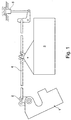
- Figure 1 depicts an electrically operable motor vehicle door lock 1.
- the motor vehicle door lock 1 has, for example, a locking element 2, which in exemplary embodiments is led to outside of the motor vehicle door lock 1, merely to clarify the principle of operation.
- the locking element, or the locking lever 2 which is realized at this location, is acted on by a motor 3, with an actuating element 4 interposed in this example, which in the present exemplary embodiment is an actuating rod 4.
- the actuating rod 4 is coupled mechanically with an inside locking knob 5.
- the solid-line position in Figure 1 corresponds to the "locked" position of the motor vehicle door lock, assumed in the present exemplary embodiment in normal operation.
- the dot-dash position of the actuating rod 4 and also of the locking lever 2 belongs to the "unlocked" position of the motor vehicle door lock 1.
- the locking knob 5 then assumes a raised position in comparison.
- the motor 3 acting on the locking element 2 is supplied with the requisite electrical energy with the aid of a main energy source.
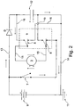
- the normal operation and the "locked" position of the locking element 2, according to Figure 1 in the example, correspond to a switch 7 in the circuit diagram according to Figure 2 being closed, as the solid-line position makes clear.
- An electric current then flows starting from the main energy source 6 or its indicated positive pole through the switch 7, another switch 8, through the motor 3, and by way of an additional switch 8 and a junction point 10, finally to the ground 11.
- the main energy source 6 is the battery located in the motor vehicle, or the storage battery there.
- the switch 7 is basically an optional switch.
- an emergency energy source 12 is also realized.
- the emergency energy source 12 is a capacitor, although the emergency energy source 12 is not limited to a capacitor.
- the motor 3 is supplied with the requisite electrical energy with the aid of the emergency energy source 12, so that the motor 3 is at least able to perform at least an emergency operation described in greater detail below.
- the emergency operation is designed in exemplary embodiments so that the motor 3, corresponding to the depiction in Figure 1 , guides the locking element or locking lever 2 to the dot-dashed "unlocked” position. The same then holds for the inside locking knob 5, and consequently for the motor vehicle door lock 1 as a whole. That is, in an emergency operation the motor vehicle door lock 1 is transferred to its functional position "unlocked” with the aid of emergency energy source 12, and consequently can be opened without problem both from inside and from outside the motor vehicle.
- the supply of energy to the motor 3 can be switched over automatically and without delay from the main energy source 6 to the emergency energy source 12 in the case of such a crash or in an accident, according to operation of the switching element 8, 9, which is actuated by the main energy source 6.
- the switching element 8, 9 connects the emergency source 12 to the motor 3 electrically in the event of failure of the main energy source 6.
- the switching element 8, 9 thereby provides simultaneously for the described emergency operation.
- the switching element 8, 9 can be guided into at least two selector positions. These two selector positions correspond on the one hand to the functional position "main energy source 6 on; emergency energy source 12 off,” and on the other hand “main energy source 6 off; emergency energy source 12 on.”
- the emergency energy source 12 is switched in parallel to the main energy source 6. Furthermore, the emergency energy source 12 is supplied with electrical energy from the main energy source 6. To this end, a positive line 13 is supplied on the one hand, and on the other hand a ground line 14 is supplied which is connected to the ground 11. That is, the main energy source 6 and the emergency energy source 12 are connected on the one hand to the common positive connecting line 13, as well as both to ground 11 on the other hand through the common ground line 14.
- a flow control valve D is tied into positive connecting line 13.
- the flow control valve is a diode D, which may be a semiconductor diode.
- the diode D ensures that the current coming from the main energy source 6 can flow on the one hand to charge the emergency energy source 12 and on the other hand to supply the motor 3, only in the indicated arrow direction in each case, and that a flow of current in the opposite direction is not possible.
- the capacitor or the emergency energy source 12 acts as an open switch as a result of the DC voltage present; that is, no additional current is able to flow through the emergency energy source 12.
- the switching element 8, 9 is equipped with a control circuit 15 on the input side and a working circuit 16 on the output side. It can be seen that the emergency energy source 12 is situated in the working circuit 16. In contrast, the motor 3, and also the main energy source 6 are located in the control circuit 15 of the switching element 8, 9.
- the two poles of the emergency energy source 12 are connected to the control circuit 15 through the working circuit 16 and the two switches 8, provided that the two switches 8 are in their dashed (open) position. That is, in the open position both connection ends of the emergency energy source 12 are connected to the corresponding switches 8 of the switching element 8, 9. Furthermore, both switches 8 of the switching element 8, 9 are actuated synchronously, and reflect the two basic selector positions of the switching element 8, 9 mentioned previously, i.e., "main energy source 6 on; emergency energy source 12 off" on the one hand, and "main energy source 6 off; emergency energy source 12 on” on the other hand.
- the switching element 8, 9 is an electromagnetically operated remote-controlled switch, in particular a relay 8, 9.
- the relay 8, 9 is made up of the two synchronously actuated switches 8 on the one hand and a coil 9 shown as outline by the dashed line. In normal operation and with the main energy source 6 intact, the two switches 8 are closed, corresponding to the solid-line position in Figure 2 .
- the electric current coming from the positive pole of the main energy source 6 flows through the coil 9.
- the current flows from the positive pole of the main energy source 6 through the closed switch 7, the switch 8, through the motor 3 and additional switch 8 to the junction 10 and on to the ground 11.
- the coil 9, through which current flows simultaneously and in parallel here, ensures in this connection that the two switches 8 are attracted by the magnetic field of the coil 9 and assume the closed position corresponding to the solid-line position in Figure 2 .
- the switching element 8, 9 is consequently in the selector position "main energy source 6 on; emergency energy source 12 off," because the emergency energy source 12 in the working circuit 16 is uncoupled from the motor 3 by the respective closed switch 8.
- the locking element 2 maintains its "locked” position in the example, due to mass inertia and/or friction in motor 3.
- the two switches 8 are no longer attracted by the coil 9, and move to the dashed (open) position corresponding to Figure 2 , for example with spring support.
- the emergency energy source 12 is now connected to the motor 3 through the switch 8, which is in the dashed position.
- a current indicated in Figure 2 coming from the positive pole of the emergency energy source 12, can flow through the upper switch 8, the motor 3 and the additional switch 8 to the junction point 10, and then to the ground 11.
- a reversal of direction of the electric current takes place, in comparison to normal operation.
- the motor 3 is acted on in its opposite direction.
Landscapes
- Lock And Its Accessories (AREA)
Claims (11)
- Elektrisch betriebenes Kraftfahrzeugtürschloss (1) bestehend aus: einem Gesperre (2,4) mit mindestens einem Verriegelungselement (2) und einem Betätigungselement (4), einem Motor (3), der auf das Gesperre einwirkt, mindestens einer Notstromquelle (12) für den Notbetrieb des Motors (3) bei Ausfall einer Hauptenergiequelle (6) und einem Schaltelement (8,9), das durch die Hauptenergiequelle (6) betätigt wird und ferner die Notstromquelle (12) elektrisch mit dem Motor (3) verbindet, um bei Ausfall der Hauptenergiequelle (6) den Notbetrieb sicherzustellen, dadurch gekennzeichnet, dass es sich bei dem Schaltelement (8,9), das von der Hauptenergiequelle betätigt wird, um ein Relais handelt, welches aus zwei synchron betätigten Schaltern (8) und einer Spule (9) besteht.
- Kraftfahrzeugtürschloss gemäß Anspruch 1, dadurch gekennzeichnet, dass das Schaltelement (8, 9) mindestens zwei Schaltstellungen besitzt, die die Hauptenergiequelle (6) ein- bzw. ausschalten.
- Kraftfahrzeugtürschloss gemäß Anspruch 2, dadurch gekennzeichnet, dass die beiden Schaltstellungen zum Ein- bzw. Ausschalten der Hauptenergiequelle (6) des Schaltelements (8, 9) passenden Schaltstellungen zum Aus- bzw. Einschalten der Notstromquelle (12) entsprechen.
- Kraftfahrzeugtürschloss gemäß einem der Ansprüche 1 bis 3, dadurch gekennzeichnet, dass die Notstromquelle (12) parallel zur Hauptenergiequelle (6) geschaltet ist und elektrisch durch die Hauptenergiequelle geladen wird.
- Kraftfahrzeugtürschloss gemäß einem der Ansprüche 1 bis 4, dadurch gekennzeichnet, dass die Hauptenergiequelle (6) und die Notstromquelle (12) an einen gemeinsamen Pluspol (13) und Erde (11) angeschlossen sind.
- Kraftfahrzeugtürschloss gemäß Anspruch 5, dadurch gekennzeichnet, dass der Pluspol (13) ein Stromventil (D) besitzt.
- Kraftfahrzeugtürschloss gemäß Anspruch 6, dadurch gekennzeichnet, dass das Stromventil (D) eine Halbleiterdiode ist.
- Kraftfahrzeugtürschloss gemäß einem der Ansprüche 1 bis 7, dadurch gekennzeichnet, dass Motor (3) in einen Steuerkreis (15) des Schaltelements (8,9) eingebunden ist.
- Kraftfahrzeugtürschloss gemäß einem der Ansprüche 1 bis 8, dadurch gekennzeichnet, dass sich die Notstromquelle (12) in einem Betriebsstromkreis (16) des Schaltelements (8,9) befindet.
- Kraftfahrzeugtürschloss gemäß einem der Ansprüche 2 bis 9, dadurch gekennzeichnet, dass beide Anschlüsse des Notstromkreises (12) mit entsprechenden Schaltern (8) des Schaltelements (8,9) verbunden sind.
- Kraftfahrzeugtürschloss gemäß Anspruch 10, dadurch gekennzeichnet, dass die beiden Schalter (8) des Schaltelements (8,9) den beiden Schaltstellungen entsprechen.
Applications Claiming Priority (2)
| Application Number | Priority Date | Filing Date | Title |
|---|---|---|---|
| US13/955,586 US9719277B2 (en) | 2013-07-31 | 2013-07-31 | Electrically operable motor vehicle door lock |
| PCT/IB2014/001300 WO2015015258A2 (en) | 2013-07-31 | 2014-07-09 | Electrically operable motor vehicle door lock |
Publications (2)
| Publication Number | Publication Date |
|---|---|
| EP3027832A2 EP3027832A2 (de) | 2016-06-08 |
| EP3027832B1 true EP3027832B1 (de) | 2017-09-06 |
Family
ID=51542397
Family Applications (1)
| Application Number | Title | Priority Date | Filing Date |
|---|---|---|---|
| EP14766522.8A Active EP3027832B1 (de) | 2013-07-31 | 2014-07-09 | Elektrisch bedienbares kraftfahrzeugtürschloss |
Country Status (4)
| Country | Link |
|---|---|
| US (1) | US9719277B2 (de) |
| EP (1) | EP3027832B1 (de) |
| CN (1) | CN105593446B (de) |
| WO (1) | WO2015015258A2 (de) |
Families Citing this family (9)
| Publication number | Priority date | Publication date | Assignee | Title |
|---|---|---|---|---|
| CN105102745B (zh) | 2012-12-24 | 2019-05-28 | 麦格纳覆盖件有限公司 | 机动车辆闭合装置的装备有改进备用能源的电子锁闩 |
| WO2014156016A1 (ja) * | 2013-03-29 | 2014-10-02 | パナソニック株式会社 | ドアラッチ装置とそれを搭載した移動体 |
| DE102013112706A1 (de) | 2013-11-18 | 2015-05-21 | Illinois Tool Works Inc. | System aus einem Türgriff und einer Betätigungseinrichtung für den Türgriff |
| CN113853466A (zh) | 2019-05-23 | 2021-12-28 | 麦格纳覆盖件有限公司 | 具有混合备用能量源的闩锁组件 |
| DE102019134801A1 (de) * | 2019-12-17 | 2021-06-17 | Brose Fahrzeugteile Se & Co. Kommanditgesellschaft, Bamberg | Steueranordnung für den Betrieb eines Kaftfahrzeugschließsystems |
| DE102020104846A1 (de) * | 2020-02-25 | 2021-08-26 | Brose Fahrzeugteile Se & Co. Kommanditgesellschaft, Bamberg | Verfahren zum Betrieb eines Kraftfahrzeugschließsystems |
| DE102020113069A1 (de) * | 2020-05-14 | 2021-11-18 | Kiekert Aktiengesellschaft | Kraftfahrzeug-Tür |
| DE102021117217A1 (de) * | 2021-07-05 | 2023-01-05 | Kiekert Aktiengesellschaft | Türschloss, insbesondere Kraftfahrzeug-Türschloss |
| DE102025126299A1 (de) * | 2024-07-05 | 2026-01-08 | Illinois Tool Works Inc. | Bündiger türgriff, fahrzeug, das diesen aufweist, und verfahren zur steuerung eines fahrzeugs |
Family Cites Families (17)
| Publication number | Priority date | Publication date | Assignee | Title |
|---|---|---|---|---|
| US3631257A (en) * | 1970-06-01 | 1971-12-28 | Union Carbide Corp | Automatic power switching unit |
| DE2540675A1 (de) | 1975-09-12 | 1977-03-24 | Kiekert Soehne Arn | Zentrale verriegelungseinrichtung fuer fahrzeugtueren |
| DE2911630C2 (de) | 1979-03-24 | 1982-10-14 | Kiekert GmbH & Co KG, 5628 Heiligenhaus | Elektrische Zentralverriegelungsvorrichtung für Kraftfahrzeugtüren |
| US5225761A (en) * | 1992-01-15 | 1993-07-06 | Wells Marine Technology, Inc. | Battery management system |
| US5547208A (en) * | 1995-03-14 | 1996-08-20 | Dennis L. Chappell | Vehicle safety exit apparatus |
| DE19633202C1 (de) | 1996-08-17 | 1997-09-11 | Kiekert Ag | Steueranlage für ein Kraftfahrzeug mit zusätzlicher Notbetriebseinrichtung |
| JP2000064685A (ja) * | 1998-08-26 | 2000-02-29 | Denso Corp | ドアロック操作装置 |
| US6265851B1 (en) * | 1999-06-11 | 2001-07-24 | Pri Automation, Inc. | Ultracapacitor power supply for an electric vehicle |
| FR2805843B1 (fr) | 2000-03-03 | 2003-09-12 | Valeo Securite Habitacle | Ensemble de verrouillage d'une porte de vehicule automobile et procede de test du bon fonctionnement d'un module de serrure de cet ensemble |
| FR2835866B1 (fr) * | 2002-02-12 | 2004-08-20 | Meritor Light Vehicle Sys Ltd | Systeme de decondamnation d'ouvrant de vehicule automobile |
| FR2835867B1 (fr) * | 2002-02-12 | 2004-08-20 | Meritor Light Vehicle Sys Ltd | Serrure de vehicule automobile |
| FR2871831B1 (fr) | 2004-06-18 | 2006-09-08 | Arvinmeritor Light Vehicle Sys | Serrure a ouverture electrique |
| FR2874136B1 (fr) | 2004-08-09 | 2009-11-20 | Valeo Securite Habitacle | Dispositif d'alimentation pour appareils electriques d'actionnement dans les vehicules automobiles |
| DE102009013650A1 (de) | 2009-03-17 | 2010-09-23 | Continental Automotive Gmbh | Anordnung zur Entriegelung eines Schlosses |
| JP5204151B2 (ja) * | 2010-05-28 | 2013-06-05 | 株式会社ホンダロック | 車両におけるドア関連補機用電気アクチュエータの電力供給制御装置 |
| US8884588B2 (en) * | 2010-07-29 | 2014-11-11 | Panasonic Corporation | Battery warming circuit and battery warming apparatus |
| CN105102745B (zh) * | 2012-12-24 | 2019-05-28 | 麦格纳覆盖件有限公司 | 机动车辆闭合装置的装备有改进备用能源的电子锁闩 |
-
2013
- 2013-07-31 US US13/955,586 patent/US9719277B2/en active Active
-
2014
- 2014-07-09 CN CN201480054372.0A patent/CN105593446B/zh active Active
- 2014-07-09 WO PCT/IB2014/001300 patent/WO2015015258A2/en not_active Ceased
- 2014-07-09 EP EP14766522.8A patent/EP3027832B1/de active Active
Non-Patent Citations (1)
| Title |
|---|
| None * |
Also Published As
| Publication number | Publication date |
|---|---|
| US20150035297A1 (en) | 2015-02-05 |
| US9719277B2 (en) | 2017-08-01 |
| WO2015015258A3 (en) | 2015-04-30 |
| EP3027832A2 (de) | 2016-06-08 |
| WO2015015258A2 (en) | 2015-02-05 |
| CN105593446B (zh) | 2018-06-19 |
| CN105593446A (zh) | 2016-05-18 |
Similar Documents
| Publication | Publication Date | Title |
|---|---|---|
| US9719277B2 (en) | Electrically operable motor vehicle door lock | |
| CN101097633B (zh) | 电子电路装置 | |
| JP6213927B2 (ja) | 自動車両ドアロック | |
| CN110924765B (zh) | 具有动力释放机构和马达控制系统的闭合闩锁组件 | |
| EP1060922B1 (de) | Schaltkreis und Verfahren zur Steuerung fremdkraftsbetriebener Fensterheber, Schiebedächer oder Türschlösser in Kraftfahrzeugen | |
| CN107448071B (zh) | 具有机械备用和电子超控取消特征的电子闩锁 | |
| US7532098B2 (en) | Actuator | |
| US20180328086A1 (en) | Motor vehicle door lock | |
| CN223707362U (zh) | 用于运行机动车闭锁系统的控制组件以及用于机动车的机动车闭锁系统 | |
| CN102918221B (zh) | 车辆中的车门相关辅机用电致动器的电力提供控制装置 | |
| US20180135338A1 (en) | Method for controlling a motor vehicle door lock | |
| CN110857606B (zh) | 针对车辆的发动机罩的锁 | |
| EP2336465A2 (de) | Schaltung und Verfahren gegen ungewolltes Öffnen einer Fahrzeugtür | |
| US11965596B2 (en) | Parking lock actuation system with electromechanical locking function, drive device, and actuation method | |
| RU2463426C2 (ru) | Электрически приводимая поворотная стойка для транспортных средств для общественных пассажирских перевозок с приводным блоком | |
| US7550867B2 (en) | Method and safety system for a displacement device of a motor vehicle | |
| DE3530834A1 (de) | Zentralverriegelungseinrichtung | |
| CN118451238A (zh) | 机动车锁,特别是机动车门锁 | |
| US20020050720A1 (en) | Coupling device for door locking systems | |
| DE102006009835A1 (de) | Elektrisches Türschloß | |
| GB2193755A (en) | Central locking installations for motor vehicles | |
| DE102009059084A1 (de) | Schaltung und Verfahren gegen ungewolltes Öffnen einer Fahrzeugtür | |
| KR0174057B1 (ko) | 자동차의 주행중 도어 열림방지장치 | |
| EP0939185B1 (de) | Verfahren und Einrichtung zur Entriegelung einer Tür, insbesondere einer Kraftfahrzeugtür | |
| CN121088251A (zh) | 一种紧急解锁装置及汽车 |
Legal Events
| Date | Code | Title | Description |
|---|---|---|---|
| PUAI | Public reference made under article 153(3) epc to a published international application that has entered the european phase |
Free format text: ORIGINAL CODE: 0009012 |
|
| 17P | Request for examination filed |
Effective date: 20160218 |
|
| AK | Designated contracting states |
Kind code of ref document: A2 Designated state(s): AL AT BE BG CH CY CZ DE DK EE ES FI FR GB GR HR HU IE IS IT LI LT LU LV MC MK MT NL NO PL PT RO RS SE SI SK SM TR |
|
| AX | Request for extension of the european patent |
Extension state: BA ME |
|
| DAX | Request for extension of the european patent (deleted) | ||
| GRAP | Despatch of communication of intention to grant a patent |
Free format text: ORIGINAL CODE: EPIDOSNIGR1 |
|
| INTG | Intention to grant announced |
Effective date: 20170519 |
|
| GRAS | Grant fee paid |
Free format text: ORIGINAL CODE: EPIDOSNIGR3 |
|
| GRAA | (expected) grant |
Free format text: ORIGINAL CODE: 0009210 |
|
| AK | Designated contracting states |
Kind code of ref document: B1 Designated state(s): AL AT BE BG CH CY CZ DE DK EE ES FI FR GB GR HR HU IE IS IT LI LT LU LV MC MK MT NL NO PL PT RO RS SE SI SK SM TR |
|
| REG | Reference to a national code |
Ref country code: GB Ref legal event code: FG4D |
|
| REG | Reference to a national code |
Ref country code: CH Ref legal event code: EP Ref country code: AT Ref legal event code: REF Ref document number: 926106 Country of ref document: AT Kind code of ref document: T Effective date: 20170915 |
|
| REG | Reference to a national code |
Ref country code: IE Ref legal event code: FG4D |
|
| REG | Reference to a national code |
Ref country code: DE Ref legal event code: R096 Ref document number: 602014014271 Country of ref document: DE |
|
| REG | Reference to a national code |
Ref country code: NL Ref legal event code: MP Effective date: 20170906 |
|
| REG | Reference to a national code |
Ref country code: LT Ref legal event code: MG4D |
|
| PG25 | Lapsed in a contracting state [announced via postgrant information from national office to epo] |
Ref country code: SE Free format text: LAPSE BECAUSE OF FAILURE TO SUBMIT A TRANSLATION OF THE DESCRIPTION OR TO PAY THE FEE WITHIN THE PRESCRIBED TIME-LIMIT Effective date: 20170906 Ref country code: HR Free format text: LAPSE BECAUSE OF FAILURE TO SUBMIT A TRANSLATION OF THE DESCRIPTION OR TO PAY THE FEE WITHIN THE PRESCRIBED TIME-LIMIT Effective date: 20170906 Ref country code: LT Free format text: LAPSE BECAUSE OF FAILURE TO SUBMIT A TRANSLATION OF THE DESCRIPTION OR TO PAY THE FEE WITHIN THE PRESCRIBED TIME-LIMIT Effective date: 20170906 Ref country code: NO Free format text: LAPSE BECAUSE OF FAILURE TO SUBMIT A TRANSLATION OF THE DESCRIPTION OR TO PAY THE FEE WITHIN THE PRESCRIBED TIME-LIMIT Effective date: 20171206 Ref country code: FI Free format text: LAPSE BECAUSE OF FAILURE TO SUBMIT A TRANSLATION OF THE DESCRIPTION OR TO PAY THE FEE WITHIN THE PRESCRIBED TIME-LIMIT Effective date: 20170906 |
|
| REG | Reference to a national code |
Ref country code: AT Ref legal event code: MK05 Ref document number: 926106 Country of ref document: AT Kind code of ref document: T Effective date: 20170906 |
|
| PG25 | Lapsed in a contracting state [announced via postgrant information from national office to epo] |
Ref country code: GR Free format text: LAPSE BECAUSE OF FAILURE TO SUBMIT A TRANSLATION OF THE DESCRIPTION OR TO PAY THE FEE WITHIN THE PRESCRIBED TIME-LIMIT Effective date: 20171207 Ref country code: LV Free format text: LAPSE BECAUSE OF FAILURE TO SUBMIT A TRANSLATION OF THE DESCRIPTION OR TO PAY THE FEE WITHIN THE PRESCRIBED TIME-LIMIT Effective date: 20170906 Ref country code: BG Free format text: LAPSE BECAUSE OF FAILURE TO SUBMIT A TRANSLATION OF THE DESCRIPTION OR TO PAY THE FEE WITHIN THE PRESCRIBED TIME-LIMIT Effective date: 20171206 Ref country code: ES Free format text: LAPSE BECAUSE OF FAILURE TO SUBMIT A TRANSLATION OF THE DESCRIPTION OR TO PAY THE FEE WITHIN THE PRESCRIBED TIME-LIMIT Effective date: 20170906 Ref country code: RS Free format text: LAPSE BECAUSE OF FAILURE TO SUBMIT A TRANSLATION OF THE DESCRIPTION OR TO PAY THE FEE WITHIN THE PRESCRIBED TIME-LIMIT Effective date: 20170906 |
|
| PG25 | Lapsed in a contracting state [announced via postgrant information from national office to epo] |
Ref country code: NL Free format text: LAPSE BECAUSE OF FAILURE TO SUBMIT A TRANSLATION OF THE DESCRIPTION OR TO PAY THE FEE WITHIN THE PRESCRIBED TIME-LIMIT Effective date: 20170906 |
|
| PG25 | Lapsed in a contracting state [announced via postgrant information from national office to epo] |
Ref country code: PL Free format text: LAPSE BECAUSE OF FAILURE TO SUBMIT A TRANSLATION OF THE DESCRIPTION OR TO PAY THE FEE WITHIN THE PRESCRIBED TIME-LIMIT Effective date: 20170906 Ref country code: RO Free format text: LAPSE BECAUSE OF FAILURE TO SUBMIT A TRANSLATION OF THE DESCRIPTION OR TO PAY THE FEE WITHIN THE PRESCRIBED TIME-LIMIT Effective date: 20170906 |
|
| PG25 | Lapsed in a contracting state [announced via postgrant information from national office to epo] |
Ref country code: SM Free format text: LAPSE BECAUSE OF FAILURE TO SUBMIT A TRANSLATION OF THE DESCRIPTION OR TO PAY THE FEE WITHIN THE PRESCRIBED TIME-LIMIT Effective date: 20170906 Ref country code: AT Free format text: LAPSE BECAUSE OF FAILURE TO SUBMIT A TRANSLATION OF THE DESCRIPTION OR TO PAY THE FEE WITHIN THE PRESCRIBED TIME-LIMIT Effective date: 20170906 Ref country code: SK Free format text: LAPSE BECAUSE OF FAILURE TO SUBMIT A TRANSLATION OF THE DESCRIPTION OR TO PAY THE FEE WITHIN THE PRESCRIBED TIME-LIMIT Effective date: 20170906 Ref country code: IS Free format text: LAPSE BECAUSE OF FAILURE TO SUBMIT A TRANSLATION OF THE DESCRIPTION OR TO PAY THE FEE WITHIN THE PRESCRIBED TIME-LIMIT Effective date: 20180106 Ref country code: IT Free format text: LAPSE BECAUSE OF FAILURE TO SUBMIT A TRANSLATION OF THE DESCRIPTION OR TO PAY THE FEE WITHIN THE PRESCRIBED TIME-LIMIT Effective date: 20170906 Ref country code: EE Free format text: LAPSE BECAUSE OF FAILURE TO SUBMIT A TRANSLATION OF THE DESCRIPTION OR TO PAY THE FEE WITHIN THE PRESCRIBED TIME-LIMIT Effective date: 20170906 |
|
| REG | Reference to a national code |
Ref country code: DE Ref legal event code: R097 Ref document number: 602014014271 Country of ref document: DE |
|
| PLBE | No opposition filed within time limit |
Free format text: ORIGINAL CODE: 0009261 |
|
| STAA | Information on the status of an ep patent application or granted ep patent |
Free format text: STATUS: NO OPPOSITION FILED WITHIN TIME LIMIT |
|
| REG | Reference to a national code |
Ref country code: FR Ref legal event code: PLFP Year of fee payment: 5 |
|
| PG25 | Lapsed in a contracting state [announced via postgrant information from national office to epo] |
Ref country code: DK Free format text: LAPSE BECAUSE OF FAILURE TO SUBMIT A TRANSLATION OF THE DESCRIPTION OR TO PAY THE FEE WITHIN THE PRESCRIBED TIME-LIMIT Effective date: 20170906 |
|
| 26N | No opposition filed |
Effective date: 20180607 |
|
| PG25 | Lapsed in a contracting state [announced via postgrant information from national office to epo] |
Ref country code: SI Free format text: LAPSE BECAUSE OF FAILURE TO SUBMIT A TRANSLATION OF THE DESCRIPTION OR TO PAY THE FEE WITHIN THE PRESCRIBED TIME-LIMIT Effective date: 20170906 |
|
| REG | Reference to a national code |
Ref country code: CH Ref legal event code: PL |
|
| GBPC | Gb: european patent ceased through non-payment of renewal fee |
Effective date: 20180709 |
|
| PG25 | Lapsed in a contracting state [announced via postgrant information from national office to epo] |
Ref country code: MC Free format text: LAPSE BECAUSE OF FAILURE TO SUBMIT A TRANSLATION OF THE DESCRIPTION OR TO PAY THE FEE WITHIN THE PRESCRIBED TIME-LIMIT Effective date: 20170906 Ref country code: LU Free format text: LAPSE BECAUSE OF NON-PAYMENT OF DUE FEES Effective date: 20180709 |
|
| REG | Reference to a national code |
Ref country code: BE Ref legal event code: MM Effective date: 20180731 |
|
| REG | Reference to a national code |
Ref country code: IE Ref legal event code: MM4A |
|
| PG25 | Lapsed in a contracting state [announced via postgrant information from national office to epo] |
Ref country code: IE Free format text: LAPSE BECAUSE OF NON-PAYMENT OF DUE FEES Effective date: 20180709 Ref country code: GB Free format text: LAPSE BECAUSE OF NON-PAYMENT OF DUE FEES Effective date: 20180709 Ref country code: CH Free format text: LAPSE BECAUSE OF NON-PAYMENT OF DUE FEES Effective date: 20180731 Ref country code: LI Free format text: LAPSE BECAUSE OF NON-PAYMENT OF DUE FEES Effective date: 20180731 |
|
| PG25 | Lapsed in a contracting state [announced via postgrant information from national office to epo] |
Ref country code: BE Free format text: LAPSE BECAUSE OF NON-PAYMENT OF DUE FEES Effective date: 20180731 |
|
| PG25 | Lapsed in a contracting state [announced via postgrant information from national office to epo] |
Ref country code: MT Free format text: LAPSE BECAUSE OF NON-PAYMENT OF DUE FEES Effective date: 20180709 |
|
| PG25 | Lapsed in a contracting state [announced via postgrant information from national office to epo] |
Ref country code: TR Free format text: LAPSE BECAUSE OF FAILURE TO SUBMIT A TRANSLATION OF THE DESCRIPTION OR TO PAY THE FEE WITHIN THE PRESCRIBED TIME-LIMIT Effective date: 20170906 |
|
| PG25 | Lapsed in a contracting state [announced via postgrant information from national office to epo] |
Ref country code: PT Free format text: LAPSE BECAUSE OF FAILURE TO SUBMIT A TRANSLATION OF THE DESCRIPTION OR TO PAY THE FEE WITHIN THE PRESCRIBED TIME-LIMIT Effective date: 20170906 |
|
| PG25 | Lapsed in a contracting state [announced via postgrant information from national office to epo] |
Ref country code: MK Free format text: LAPSE BECAUSE OF NON-PAYMENT OF DUE FEES Effective date: 20170906 Ref country code: CY Free format text: LAPSE BECAUSE OF FAILURE TO SUBMIT A TRANSLATION OF THE DESCRIPTION OR TO PAY THE FEE WITHIN THE PRESCRIBED TIME-LIMIT Effective date: 20170906 Ref country code: HU Free format text: LAPSE BECAUSE OF FAILURE TO SUBMIT A TRANSLATION OF THE DESCRIPTION OR TO PAY THE FEE WITHIN THE PRESCRIBED TIME-LIMIT; INVALID AB INITIO Effective date: 20140709 |
|
| PG25 | Lapsed in a contracting state [announced via postgrant information from national office to epo] |
Ref country code: AL Free format text: LAPSE BECAUSE OF FAILURE TO SUBMIT A TRANSLATION OF THE DESCRIPTION OR TO PAY THE FEE WITHIN THE PRESCRIBED TIME-LIMIT Effective date: 20170906 |
|
| P01 | Opt-out of the competence of the unified patent court (upc) registered |
Effective date: 20230529 |
|
| PGFP | Annual fee paid to national office [announced via postgrant information from national office to epo] |
Ref country code: CZ Payment date: 20250626 Year of fee payment: 12 |
|
| PGFP | Annual fee paid to national office [announced via postgrant information from national office to epo] |
Ref country code: DE Payment date: 20250722 Year of fee payment: 12 |
|
| PGFP | Annual fee paid to national office [announced via postgrant information from national office to epo] |
Ref country code: FR Payment date: 20250723 Year of fee payment: 12 |