EP3025887B1 - Klimaanlage für ein fahrzeug - Google Patents
Klimaanlage für ein fahrzeug Download PDFInfo
- Publication number
- EP3025887B1 EP3025887B1 EP14830350.6A EP14830350A EP3025887B1 EP 3025887 B1 EP3025887 B1 EP 3025887B1 EP 14830350 A EP14830350 A EP 14830350A EP 3025887 B1 EP3025887 B1 EP 3025887B1
- Authority
- EP
- European Patent Office
- Prior art keywords
- refrigerant
- water
- heat exchanger
- switch
- state
- Prior art date
- Legal status (The legal status is an assumption and is not a legal conclusion. Google has not performed a legal analysis and makes no representation as to the accuracy of the status listed.)
- Not-in-force
Links
Images


Classifications
-
- F—MECHANICAL ENGINEERING; LIGHTING; HEATING; WEAPONS; BLASTING
- F25—REFRIGERATION OR COOLING; COMBINED HEATING AND REFRIGERATION SYSTEMS; HEAT PUMP SYSTEMS; MANUFACTURE OR STORAGE OF ICE; LIQUEFACTION SOLIDIFICATION OF GASES
- F25B—REFRIGERATION MACHINES, PLANTS OR SYSTEMS; COMBINED HEATING AND REFRIGERATION SYSTEMS; HEAT PUMP SYSTEMS
- F25B41/00—Fluid-circulation arrangements
- F25B41/20—Disposition of valves, e.g. of on-off valves or flow control valves
- F25B41/24—Arrangement of shut-off valves for disconnecting a part of the refrigerant cycle, e.g. an outdoor part
-
- B—PERFORMING OPERATIONS; TRANSPORTING
- B60—VEHICLES IN GENERAL
- B60H—ARRANGEMENTS OF HEATING, COOLING, VENTILATING OR OTHER AIR-TREATING DEVICES SPECIALLY ADAPTED FOR PASSENGER OR GOODS SPACES OF VEHICLES
- B60H1/00—Heating, cooling or ventilating [HVAC] devices
- B60H1/00007—Combined heating, ventilating, or cooling devices
-
- B—PERFORMING OPERATIONS; TRANSPORTING
- B60—VEHICLES IN GENERAL
- B60H—ARRANGEMENTS OF HEATING, COOLING, VENTILATING OR OTHER AIR-TREATING DEVICES SPECIALLY ADAPTED FOR PASSENGER OR GOODS SPACES OF VEHICLES
- B60H1/00—Heating, cooling or ventilating [HVAC] devices
- B60H1/00642—Control systems or circuits; Control members or indication devices for heating, cooling or ventilating devices
- B60H1/00814—Control systems or circuits characterised by their output, for controlling particular components of the heating, cooling or ventilating installation
- B60H1/00878—Control systems or circuits characterised by their output, for controlling particular components of the heating, cooling or ventilating installation the components being temperature regulating devices
- B60H1/00899—Controlling the flow of liquid in a heat pump system
-
- B—PERFORMING OPERATIONS; TRANSPORTING
- B60—VEHICLES IN GENERAL
- B60H—ARRANGEMENTS OF HEATING, COOLING, VENTILATING OR OTHER AIR-TREATING DEVICES SPECIALLY ADAPTED FOR PASSENGER OR GOODS SPACES OF VEHICLES
- B60H1/00—Heating, cooling or ventilating [HVAC] devices
- B60H1/32—Cooling devices
- B60H1/3204—Cooling devices using compression
- B60H1/3228—Cooling devices using compression characterised by refrigerant circuit configurations
- B60H1/32284—Cooling devices using compression characterised by refrigerant circuit configurations comprising two or more secondary circuits, e.g. at evaporator and condenser side
-
- B—PERFORMING OPERATIONS; TRANSPORTING
- B60—VEHICLES IN GENERAL
- B60K—ARRANGEMENT OR MOUNTING OF PROPULSION UNITS OR OF TRANSMISSIONS IN VEHICLES; ARRANGEMENT OR MOUNTING OF PLURAL DIVERSE PRIME-MOVERS IN VEHICLES; AUXILIARY DRIVES FOR VEHICLES; INSTRUMENTATION OR DASHBOARDS FOR VEHICLES; ARRANGEMENTS IN CONNECTION WITH COOLING, AIR INTAKE, GAS EXHAUST OR FUEL SUPPLY OF PROPULSION UNITS IN VEHICLES
- B60K11/00—Arrangement in connection with cooling of propulsion units
- B60K11/02—Arrangement in connection with cooling of propulsion units with liquid cooling
-
- F—MECHANICAL ENGINEERING; LIGHTING; HEATING; WEAPONS; BLASTING
- F25—REFRIGERATION OR COOLING; COMBINED HEATING AND REFRIGERATION SYSTEMS; HEAT PUMP SYSTEMS; MANUFACTURE OR STORAGE OF ICE; LIQUEFACTION SOLIDIFICATION OF GASES
- F25B—REFRIGERATION MACHINES, PLANTS OR SYSTEMS; COMBINED HEATING AND REFRIGERATION SYSTEMS; HEAT PUMP SYSTEMS
- F25B41/00—Fluid-circulation arrangements
- F25B41/20—Disposition of valves, e.g. of on-off valves or flow control valves
-
- F—MECHANICAL ENGINEERING; LIGHTING; HEATING; WEAPONS; BLASTING
- F25—REFRIGERATION OR COOLING; COMBINED HEATING AND REFRIGERATION SYSTEMS; HEAT PUMP SYSTEMS; MANUFACTURE OR STORAGE OF ICE; LIQUEFACTION SOLIDIFICATION OF GASES
- F25B—REFRIGERATION MACHINES, PLANTS OR SYSTEMS; COMBINED HEATING AND REFRIGERATION SYSTEMS; HEAT PUMP SYSTEMS
- F25B5/00—Compression machines, plants or systems, with several evaporator circuits, e.g. for varying refrigerating capacity
- F25B5/02—Compression machines, plants or systems, with several evaporator circuits, e.g. for varying refrigerating capacity arranged in parallel
-
- B—PERFORMING OPERATIONS; TRANSPORTING
- B60—VEHICLES IN GENERAL
- B60H—ARRANGEMENTS OF HEATING, COOLING, VENTILATING OR OTHER AIR-TREATING DEVICES SPECIALLY ADAPTED FOR PASSENGER OR GOODS SPACES OF VEHICLES
- B60H1/00—Heating, cooling or ventilating [HVAC] devices
- B60H1/00642—Control systems or circuits; Control members or indication devices for heating, cooling or ventilating devices
- B60H1/00814—Control systems or circuits characterised by their output, for controlling particular components of the heating, cooling or ventilating installation
- B60H1/00878—Control systems or circuits characterised by their output, for controlling particular components of the heating, cooling or ventilating installation the components being temperature regulating devices
- B60H2001/00928—Control systems or circuits characterised by their output, for controlling particular components of the heating, cooling or ventilating installation the components being temperature regulating devices comprising a secondary circuit
-
- B—PERFORMING OPERATIONS; TRANSPORTING
- B60—VEHICLES IN GENERAL
- B60K—ARRANGEMENT OR MOUNTING OF PROPULSION UNITS OR OF TRANSMISSIONS IN VEHICLES; ARRANGEMENT OR MOUNTING OF PLURAL DIVERSE PRIME-MOVERS IN VEHICLES; AUXILIARY DRIVES FOR VEHICLES; INSTRUMENTATION OR DASHBOARDS FOR VEHICLES; ARRANGEMENTS IN CONNECTION WITH COOLING, AIR INTAKE, GAS EXHAUST OR FUEL SUPPLY OF PROPULSION UNITS IN VEHICLES
- B60K1/00—Arrangement or mounting of electrical propulsion units
- B60K2001/003—Arrangement or mounting of electrical propulsion units with means for cooling the electrical propulsion units
- B60K2001/005—Arrangement or mounting of electrical propulsion units with means for cooling the electrical propulsion units the electric storage means
-
- F—MECHANICAL ENGINEERING; LIGHTING; HEATING; WEAPONS; BLASTING
- F25—REFRIGERATION OR COOLING; COMBINED HEATING AND REFRIGERATION SYSTEMS; HEAT PUMP SYSTEMS; MANUFACTURE OR STORAGE OF ICE; LIQUEFACTION SOLIDIFICATION OF GASES
- F25B—REFRIGERATION MACHINES, PLANTS OR SYSTEMS; COMBINED HEATING AND REFRIGERATION SYSTEMS; HEAT PUMP SYSTEMS
- F25B2339/00—Details of evaporators; Details of condensers
- F25B2339/04—Details of condensers
- F25B2339/047—Water-cooled condensers
Definitions
- the present disclosure relates to a vehicle air conditioner.
- PTL 1 discloses a vehicle air conditioner which can enhance heating performance compared to a conventional vehicle air conditioner.
- the vehicle air conditioner of PTL 1 is based on a conventional hot water heater and adding a configuration of heating coolant of a hot water heater by using a heat pump.
- a component such as an in-vehicle battery whose temperature needs to be adjusted is mounted on a vehicle. It is considered that the component whose temperature needs to be adjusted may be cooled by providing a component temperature-adjustment path in which a coolant flows for performing a heat exchange with a component, which needs a temperature adjustment, of a vehicle, and passing through an evaporator of a heat pump disclosed in PTL 1.
- the vehicle air conditioner of PTL 1 has a problem that, if the component temperature-adjustment path is simply provided passing through the evaporator, the component whose temperature needs to be adjusted cannot be sufficiently cooled. This is because engine coolant having a high temperature also passes through the evaporator.
- PTL 2 discloses another prior art vehicle air conditioner.
- the present disclosure provides a vehicle air conditioner which has a configuration of heating coolant in a hot water heater by using a heat pump, and sufficiently cools a component whose temperature needs to be adjusted.
- a vehicle air conditioner employs a configuration including: a component temperature-adjustment path in which a coolant flows for performing a heat exchange with a vehicle component which needs a temperature adjustment; an engine coolant path in which an engine cooling portion flows; a heater core, in which the engine coolant flowing in the engine coolant path flows, for heating air to be fed to an interior of the vehicle.
- the configuration further includes: a first water-refrigerant heat exchanger which performs a heat exchange among a low-temperature and low-pressure refrigerant of a heat pump, the coolant fed to the component temperature-adjustment path, and the engine coolant flowing in the engine coolant path; a second water-refrigerant heat exchanger which performs a heat exchange between a high-temperature and high-pressure refrigerant of the heat pump, and the engine coolant flowing in the engine coolant path; and a first switch which can switch between a state where the engine coolant flowing in the engine coolant path flows to the first water-refrigerant heat exchanger and a state where the refrigerant bypasses the first water-refrigerant heat exchanger.
- the first switch allows an engine coolant to bypass based on a configuration of a heat pump cooling device, so that it is possible to sufficiently cool a component whose temperature needs to be adjusted.
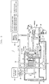
- FIG. 1 is a configuration diagram of a vehicle air conditioner according to the exemplary embodiment of the present disclosure.
- Vehicle air conditioner 1 is a device which is mounted on a vehicle including an engine (internal combustion engine) as a heat generating component, and adjusts air condition in the vehicle.
- an engine internal combustion engine
- Vehicle air conditioner 1 includes constituent unit 10, compressor (compressing machine) 38, engine cooling portion 40, heater core 44, evaporator 48, expansion valve 37, outside condenser 39, check valve 15, three-way valve 18 (corresponding to a first switch), in-vehicle battery 20, pump 21, coolant pipes which connect these components, and a refrigerant pipe.
- Heater core 44 and evaporator 48 are disposed in a suction air route of HVAC (Heating, Ventilation, and Air Conditioning) 70.
- HVAC 70 is provided with fan F1 which causes a suction air to flow.
- Compressor 38 is driven by power of an engine or electricity, and compresses a suctioned refrigerant to a high-temperature and high-pressure refrigerant and discharges the refrigerant.
- the compressed refrigerant is fed to constituent unit 10.
- Compressor 38 suctions a low-pressure refrigerant through a junction pipe from evaporator 48 or first water-refrigerant heat exchanger 11 of constituent unit 10.
- Engine cooling portion 40 includes a water jacket which causes a coolant to flow in surroundings of the engine, and a pump which causes the coolant to flow in the water jacket, and radiates heat from the engine to the coolant flowing in the water jacket.
- the pump is rotated by, for example, power of the engine.
- Engine cooling portion 40 may include a radiator which radiates heat to outside air when the amount of heat released from the engine is large.
- a coolant path (engine coolant path 19) of engine cooling portion 40 passes through constituent unit 10 and continues to heater core 44.
- the engine coolant is, for example, an antifreeze liquid such as an LLC (Long Life Coolant) and is a liquid for heat transportation.
- an antifreeze liquid such as an LLC (Long Life Coolant) and is a liquid for heat transportation.
- a configuration of transporting the engine coolant may include only the pump of engine cooling portion 40. Consequently, it is possible to reduce the cost of the vehicle air conditioner and reduce an installation space for the vehicle air conditioner.
- a pump may be added to another portion of the coolant pipe.
- Heater core 44 is a device which performs a heat exchange between an engine coolant and air, and is disposed in a suction air path of HVAC 70 which supplies air to the interior of the vehicle. Heater core 44 receives a supply of the heated engine coolant, and radiates heat on a suction air fed to the interior of the vehicle (an air-blast to the interior of the vehicle) in a heating operation. Heater core 44 can adjust the amount of air which passes according to an opening of door 44a. Door 44a can be electrically controlled to open and close. Door 44a is also referred to as a mix door.
- Evaporator 48 is a device which performs a heat exchange between a low-temperature and low-temperature refrigerant and air, and is disposed in the suction air path of HVAC 70. Evaporator 48 receives a flow of a low-temperature and low-pressure refrigerant in a cooling operation or a dehumidifying operation, and cools suction air supplied to the interior of the vehicle (an air-blast to the interior of the vehicle).
- Expansion valve 37 allows a high-pressure refrigerant to expand a low-temperature and low-pressure state, and discharges the refrigerant to evaporator 48. Expansion valve 37 is disposed close to evaporator 48. Expansion valve 37 may have a function of automatically adjusting the amount of refrigerant to discharge according to a temperature of a refrigerant fed from evaporator 48.
- Outside condenser 39 includes a path in which a refrigerant flows and a path in which air flows, is disposed at a head of the vehicle in an engine room, and performs a heat exchange between the refrigerant and outside air.
- Outside condenser 39 receives a flow of a high-temperature and high-pressure refrigerant in the cooling mode and the dehumidifying mode, and releases heat from the refrigerant to outside air. Outside air is blown to outside condenser 39 by, for example, a fan.
- Reservoir tank 39a may be provided at a side of outside condenser 39 from which the refrigerant is fed.
- the refrigerant having passed through outside condenser 39 is guided to evaporator 48 through expansion valve 37, and is also guided to constituent unit 10 by being branched.
- the engine coolant having been guided from engine cooling portion 40 passes through engine coolant path 19 and is guided to constituent unit 10.
- the engine coolant having passed through constituent unit 10 passes through heater core 44 and is guided to three-way valve 18.
- Three way valve 18 switches between a state where the engine coolant guided from heater core 44 and flowing in engine coolant path 19 flows to first water-refrigerant heat exchanger 11 included in constituent unit 10 described below, and a state where the engine coolant bypasses first water-refrigerant heat exchanger 11.
- In-vehicle battery 20 is a secondary battery which accumulates electric energy which is a driving source for a driving motor of an electric vehicle or a hybrid car, for example.
- In-vehicle battery 20 is a component whose temperature needs to be adjusted by way of cooling.
- a coolant which is an antifreeze liquid such as an LLC is used to adjust the temperature of in-vehicle battery 20.
- This coolant passes through component temperature-adjustment path 22 and is guided to constituent unit 10.
- the coolant having been cooled by constituent unit 10 passes through component temperature-adjustment path 22 and is guided to in-vehicle battery 20.
- Pump 21 is used to circulate the coolant in component temperature-adjustment path 22.
- Component temperature-adjustment path 22 and engine coolant path 19 are independent paths.
- Constituent unit 10 is an integrated component which is manufactured as a single unit at a factory, and is connected with other components of vehicle air conditioner 1 by pipes in a vehicle assembly process.
- each component may be contained in one housing and integrated or each component may be integrated by being jointed.
- Constituent unit 10 includes first water-refrigerant heat exchanger 11, second water-refrigerant heat exchanger 12, ON-OFF valve (corresponding to a second switch) 13, expansion valve 14, ON-OFF valve 16 (corresponding to the second switch), and ON-OFF valve 17 (corresponding to the second switch).
- First water-refrigerant heat exchanger 11 (evaporator) includes a path in which the low-temperature and low-pressure refrigerant flows and a plurality of paths in which coolants flow, and performs a heat exchange between the refrigerant and the coolant.
- expansion valve 14 discharges the low-temperature and low-pressure refrigerant in a predetermined operation mode to transfer heat from the coolant to the low-temperature and low-pressure refrigerant.
- first water-refrigerant heat exchanger 11 vaporizes the low-temperature and low-pressure refrigerant.
- One of coolant inlets of first water-refrigerant heat exchanger 11 is connected to heater core 44 through three-way valve 18, and one of coolant outlets is connected to an inlet of engine cooling portion 40 through engine coolant path 19.
- Another one of the coolant inlets of first water-refrigerant heat exchanger 11 is connected to a coolant outlet of in-vehicle battery 20 through component temperature-adjustment path 22. Another one of the coolant outlets of first water-refrigerant heat exchanger 11 is connected to the coolant inlet of in-vehicle battery 20 through component temperature-adjustment path 22.
- the refrigerant inlet of first water-refrigerant heat exchanger 11 is connected to expansion valve 14 through a pipe, and the refrigerant outlet is connected to a pipe which joins a suction port of compressor 38.
- Second water-refrigerant heat exchanger 12 (condenser) includes a path in which the high-temperature and high-pressure refrigerant flows and a path in which a coolant flows, and performs a heat exchange between the refrigerant and the coolant.
- Second water-refrigerant heat exchanger 12 receives a flow of the high-temperature and high-pressure refrigerant fed from compressor 38 in an operation mode in which the temperature of the engine coolant is low, and releases heat from the high-temperature and high-pressure refrigerant to the coolant.
- second water-refrigerant heat exchanger 12 condenses the high-temperature and high-pressure refrigerant.
- the coolant inlet of second water-refrigerant heat exchanger 12 is connected to the outlet of engine cooling portion 40 through engine coolant path 19.
- the coolant outlet of second water-refrigerant heat exchanger 12 is connected to the inlet of heater core 44 through engine coolant path 19.
- the refrigerant inlet of second water-refrigerant heat exchanger 12 is connected to a discharge port of compressor 38 through a pipe.
- the refrigerant outlet of second water-refrigerant heat exchanger 12 is connected to ON-OFF valve 17 and expansion valve 14 through a branching pipe, and is also connected to outside condenser 39 through another branching pipe and ON-OFF valve 13.
- refrigerant having passed through outside condenser 39 and having been guided to constituent unit 10 is connected to expansion valve 14 through ON-OFF valve 16.
- ON-OFF valve 13, ON-OFF valve 16, and ON-OFF valve 17 are valves which are, for example, electrically controlled to open or close a refrigerant pipe.
- ON-OFF valve 13, ON-OFF valve 16, and ON-OFF valve 17 are, for example, solenoid valves.
- ON-OFF valve 13, ON-OFF valve 16, and ON-OFF valve 17 correspond to the second switches, and switch between a state where the refrigerant guided from second water-refrigerant heat exchanger 12 flows only to evaporator 48 among evaporator 48 and first water-refrigerant heat exchanger 11, and a state where the refrigerant flows to both of evaporator 48 and first water-refrigerant heat exchanger 11.
- Expansion valve 14 is a valve which functions as an expansion valve which allows the high-pressure refrigerant to expand to the low-temperature and low-pressure state.
- Check valve 15 is a valve which is provided between compressor 38 and evaporator 48, and prevents a reverse flow of the refrigerant in an operation mode in which the refrigerant does not flow to outside condenser 39 and evaporator 48.
- it is considered an operation mode in which ON-OFF valve 13 and ON-OFF valve 16 are closed, ON-OFF valve 17 is opened, and the refrigerant flows to a refrigerant circuit which passes through first water-refrigerant heat exchanger 11 and second water-refrigerant heat exchanger 12.
- ON-OFF valve 13 is closed, and therefore the refrigerant circuit passing through outside condenser 39 and evaporator 48 is interrupted.
- Vehicle air conditioner 1 operates by being switched to some operation modes such as a hot water heating mode, a heat pump heating mode, a temperature-adjusting mode, and a cooling mode.
- the hot water heating mode is a mode of heating the interior of the vehicle without operating the heat pump.
- the heat pump heating mode is a mode of heating the interior of the vehicle by operating the heat pump.
- the cooling mode is a mode of cooling the interior of the vehicle by an operation of the heat pump. Further, it is also possible to select a temperature adjusting mode of adjusting the temperature and the humidity of air by optionally cooling and dehumidifying air by using the low-temperature refrigerant, and heating air by using the high-temperature coolant.
- a cooling mode will be described as a typical example below.
- FIG. 2 is a diagram for illustrating an operation of the cooling mode.
- ON-OFF valve 13 is switched to open, ON-OFF valve 16 is switched to open and ON-OFF valve 17 is switched to close. Further, door 44a of heater core 44 is fully closed.
- compressor 38 When compressor 38 operates, the refrigerant circulates in order of second water-refrigerant heat exchanger 12, outside condenser 39, expansion valve 37, evaporator 48, and compressor 38. Further, the refrigerant discharged by compressor 38 circulates in order of second water-refrigerant heat exchanger 12, outside condenser 39, ON-OFF valve 16, expansion valve 14, first water-refrigerant heat exchanger 11, and compressor 38.
- three-way valve 18 (first switch) is switched such that the engine coolant guided from heater core 44 and flowing in engine coolant path 19 bypasses first water-refrigerant heat exchanger 11.
- first water-refrigerant heat exchanger 11 When the engine coolant bypasses first water-refrigerant heat exchanger 11 by three-way valve 18, only the coolant having been guided from in-vehicle battery 20 passes through first water-refrigerant heat exchanger 11. This coolant is cooled when passing through first water-refrigerant heat exchanger 11.
- the engine coolant flowing in engine coolant path 19 has a relatively high temperature because it is not cooled due to bypassesing. Heat is radiated from the coolant mainly by a radiator of engine cooling portion 40. Because the temperature of the engine becomes very high, even when the temperature of outside air is high, it is possible to adequately cool the interior of the vehicle by heat radiation from the radiator. In a configuration in which the coolant flows, a more coolant may flow to the radiator in order to lower a flow at heater core 44.
- An amount of heat radiation from the high-temperature and high-pressure refrigerant is not large in second water-refrigerant heat exchanger 12, because the temperature of the coolant of second water-refrigerant heat exchanger 12 becomes high. Accordingly, the high-temperature and high-pressure refrigerant is fed to outside condenser 39, and then condenses by radiating heat to air in outside condenser 39.
- the condensed refrigerant is fed toward evaporator 48.
- the refrigerant at first, expands at expansion valve 37 to become a low-temperature and low-pressure refrigerant, and cools an air-blast to the interior of the vehicle at evaporator 48.
- the refrigerant is vaporized by this heat exchange.
- the vaporized low-pressure refrigerant is suctioned and compressed by compressor 38.
- the temperature of the coolant flowing in second water-refrigerant heat exchanger 12, heater core 44, and first water-refrigerant heat exchanger 11 becomes high.
- an amount of heat radiation to suction air fed to the interior of the vehicle can be adjusted by adjusting an opening of door 44a of heater core 44.
- vehicle air conditioner 1 employs a basic configuration including a configuration of a hot water heater which causes an engine coolant to flow in heater core 44 to use for heating, and a configuration of a heat pump cooler which uses a low-temperature and low-pressure refrigerant of the heat pump for cooling. Further, by adding constituent unit 10 to this basic configuration, it possible to warm the interior of the vehicle by using the heat pump. With this configuration, even when the temperature of the engine is low, the operation of the heat pump makes it possible to quickly warm the interior of the vehicle with small energy.
- a basic configuration including a hot water heater which is adopted for a conventional vehicle, and a heat pump cooler which is adopted for a conventional vehicle, and sufficiently cool a component (in-vehicle battery 20) whose temperature needs to be adjusted by allowing the engine coolant to bypass by using three-way valve (first switch) 18.
- ON-OFF valve 13 In the heat pump heating mode, ON-OFF valve 13 is switched to close, ON-OFF valve 16 is switched to close, and ON-OFF valve 17 is switched to open. Further, door 44a of heater core 44 is opened (fully opened, for example).
- ON-OFF valve 13 can switch between a state where the refrigerant fed from second water-refrigerant heat exchanger 12 is fed to evaporator 48 and a state where the refrigerant is not fed to evaporator 48.
- ON-OFF valve 17 can switch between a state where the refrigerant fed from second water-refrigerant heat exchanger 12 is fed to first water-refrigerant heat exchanger 11 and a state where the refrigerant is not fed to first water-refrigerant heat exchanger 11.
- compressor 38 when compressor 38 operates, the refrigerant discharged by compressor 38 circulates in order of second water-refrigerant heat exchanger 12, expansion valve 14, first water-refrigerant heat exchanger 11, and compressor 38.
- ON-OFF valve 13, ON-OFF valve 16, and ON-OFF valve 17 can switch at least between a state of the cooling mode where the refrigerant flows to a circulation route including second water-refrigerant heat exchanger 12, outside condenser 39, evaporator 48, and compressor 38, and the refrigerant does not flow to first water-refrigerant heat exchanger 11, and a state of the heat pump heating mode where the refrigerant flows to a circulation route including second water-refrigerant heat exchanger 12, first water-refrigerant heat exchanger 11, and compressor 38.
- ON-OFF valve 13, ON-OFF valve 16, and ON-OFF valve 17 switch to the state of the heat pump heating mode, it is possible to switch three-way valve 18 (first switch) to a state where the engine coolant flows to first water-refrigerant heat exchanger 11 (does not bypass). Consequently, it is possible to realize heating by absorbing heat from both of the engine coolant flowing in engine coolant path 19 and the coolant flowing in component temperature-adjustment path 22.
- FIG. 3 is a configuration diagram of a vehicle air conditioner according to the modified example of the exemplary embodiment of the present disclosure.
- a change in a refrigerant path is added to the configuration of the exemplary embodiment in FIG. 1 .
- the same components as those components in FIG. 1 will be assigned the same reference numerals and outside condenser 39 will not be described in detail.
- ON-OFF valve 13, ON-OFF valve 16, and ON-OFF valve 17 switch between a state where the refrigerant fed from second water-refrigerant heat exchanger 12 flows only to evaporator 48 among evaporator 48 and first water-refrigerant heat exchanger 11, and a state where the refrigerant flows to both of evaporator 48 and first water-refrigerant heat exchanger 11.
- ON-OFF valve 23, ON-OFF valve 24, and ON-OFF valve 25 (second switches) switch between a state where a refrigerant branched from a refrigerant discharged by compressor 38 to be guided to second water-refrigerant heat exchanger 12 flows only to evaporator 48 among evaporator 48 and first water-refrigerant heat exchanger 11, and a state where the refrigerant flows to both of evaporator 48 and first water-refrigerant heat exchanger 11.
- a discharge port of compressor 38 is connected to ON-OFF valve 24, and is connected to ON-OFF valve 23 through a branching pipe.
- the refrigerant inlet of second water-refrigerant heat exchanger 12 is connected to a discharge port of compressor 38 through ON-OFF valve 24.
- the refrigerant outlet of second water-refrigerant heat exchanger 12 is connected to a refrigerant inlet of first water-refrigerant heat exchanger 11 through expansion valve 14.
- the refrigerant outlet of first water-refrigerant heat exchanger 11 is connected to a pipe which joins a suction port of compressor 38.
- ON-OFF valve 25 plays the same role as ON-OFF valve 16 in FIG. 1 .
- the discharge port of compressor 38 is connected to a refrigerant inlet of outside condenser 39 through a branching pipe and ON-OFF valve 23 in order.
- a refrigerant path from second water-refrigerant heat exchanger 12 to first water-refrigerant heat exchanger 11, and a refrigerant path from outside condenser 39 to evaporator 48 are different refrigerant paths.
- ON-OFF valve 23 is switched to open, ON-OFF valve 24 is switched to open, and ON-OFF valve 25 is switched to close. Further, door 44a of heater core 44 is fully closed.
- compressor 38 When compressor 38 operates, the refrigerant circulates in order of outside condenser 39, expansion valve 37, evaporator 48, and compressor 38. Further, the refrigerant discharged by compressor 38 circulates in order of outside condenser 39, ON-OFF valve 25, expansion valve 14, first water-refrigerant heat exchanger 11, and compressor 38.
- three-way valve 18 (first switch) is switched such that the engine coolant guided from heater core 44 and flowing in engine coolant path 19 bypasses first water-refrigerant heat exchanger 11.
- ON-OFF valve 23 is switched to close, ON-OFF valve 24 is switched to open, and ON-OFF valve 25 is switched to close. Furthermore, door 44a of heater core 44 is opened (fully opened, for example).
- compressor 38 when compressor 38 operates, the refrigerant discharged by compressor 38 circulates in order of second water-refrigerant heat exchanger 12, expansion valve 14, first water-refrigerant heat exchanger 11, and compressor 38.
- ON-OFF valve 23, ON-OFF valve 24, and ON-OFF valve 25 (second switches) switch to the state of the heat pump heating mode, it is possible to switch three-way valve 18 (first switch) to a state where the engine coolant flows to first water-refrigerant heat exchanger 11 (does not bypass). Consequently, it is possible to realize heating by absorbing heat from both of the engine coolant flowing in engine coolant path 19 and the coolant flowing in component temperature-adjustment path 22.
- ON-OFF valve 23, ON-OFF valve 24, and ON-OFF valve 25 can switch to a state where a refrigerant flows to a refrigerant circuit including compressor 38, second water-refrigerant heat exchanger 12, and first water-refrigerant heat exchanger 11.
- a refrigerant path from second water-refrigerant heat exchanger 12 to first water-refrigerant heat exchanger 11, and a refrigerant path from outside condenser 39 to evaporator 48 are different refrigerant paths.
- ON-OFF valve 23, ON-OFF valve 24, and ON-OFF valve 25 can switch between a state where a refrigerant flows to a refrigerant circuit including compressor 38, second water-refrigerant heat exchanger 12, and first water-refrigerant heat exchanger 11, and a state where the refrigerant flows to a refrigerant circuit including compressor 38, outside condenserr 39, and evaporator 48.
- a refrigerant path from second water-refrigerant heat exchanger 12 to first water-refrigerant heat exchanger 11, and a refrigerant path from outside condenser 39 to evaporator 48 are different refrigerant paths.
- ON-OFF valve 23, ON-OFF valve 24, and ON-OFF valve 25 can switch to a state where a refrigerant flows to a refrigerant circuit including compressor 38, second water-refrigerant heat exchanger 12, and first water-refrigerant heat exchanger 11 in the heat pump heating mode, and switch to a state where the refrigerant flows to a refrigerant circuit including compressor 38, outside condenser 39, and evaporator 48 in the cooling mode.
- vehicle air conditioner 1A includes expansion valve 14 which expands a refrigerant before the refrigerant reaches first water-refrigerant heat exchanger 11, and expansion valve 37 which expands the refrigerant before the refrigerant reaches evaporator 48. Consequently, it is possible to tune the expansion valve differently according to a plurality of different operation modes in order to match a plurality of operation modes.
- a heat exchange is performed between air and a refrigerant in the cooling mode, and a heat exchange is performed between a coolant and a refrigerant in a heat pump heating mode.
- vehicle air conditioner 1A according to the modified example hardly causes such a problem.
- three-way valve 18 adopted as the first switch has been described as an example in the above exemplary embodiment.
- three-way valve 18 is provided outside constituent unit 10 has been described as an example in the above exemplary embodiment. However, three-way valve 18 may be provided inside constituent unit 10.
- the in-vehicle battery has been described as an example of a component of the vehicle whose temperature needs to be adjusted in the above exemplary embodiment.
- the component of the vehicle whose temperature needs to be adjusted may adopt various components whose temperatures need to be adjusted such as an electric motor of an electric vehicle for driving.
- the present disclosure can be used for a vehicle air conditioner which is mounted on various vehicles such as engine cars, electric vehicles or HEV on which a component whose temperature needs to be adjusted is mounted.
Claims (15)
- Fahrzeugklimaanlage (1), die Folgendes umfasst:einen Komponententemperatureinstellweg (22), in dem zum Durchführen eines Wärmeaustauschs mit einer Fahrzeugkomponente (20), die eine Temperatureinstellung benötigt, ein Kühlmittel strömt;einen Kraftmaschinenkühlmittelweg (19), in dem ein Kraftmaschinenkühlmittel strömt, das von einem Kraftmaschinenkühlabschnitt (40) geführt wird;einen Heizeinrichtungskern (44), in dem zum Erwärmen der Luft, die einem Innenraum des Fahrzeugs zugeführt werden soll, das Kraftmaschinenkühlmittel strömt, das im Kraftmaschinenkühlmittelweg (19) strömt;einen ersten Wasser-Kältemittel-Wärmetauscher (11), der einen Wärmeaustausch zwischen einem Kältemittel mit niedriger Temperatur und niedrigem Druck einer Wärmepumpe, wobei das Kühlmittel im Komponententemperatureinstellweg (22) strömt, und dem Kraftmaschinenkühlmittel, das im Kraftmaschinenkühlmittelweg (19) strömt, durchführt;gekennzeichnet durcheinen zweiten Wasser-Kältemittel-Wärmetauscher (12), der einen Wärmeaustausch zwischen einem Kältemittel mit hoher Temperatur und hohem Druck der Wärmepumpe und dem Kraftmaschinenkühlmittel, das im Kraftmaschinenkühlmittelweg (19) strömt, durchführt; undeinen ersten Schalter (18), der zwischen einem Zustand, in dem das Kraftmaschinenkühlmittel, das im Kraftmaschinenkühlmittelweg (19) strömt, zum ersten Wasser-Kältemittel-Wärmetauscher (11) strömt, und einem Zustand, in dem das Kältemittel den ersten Wasser-Kältemittel-Wärmetauscher (11) umgeht, umschalten kann.
- Fahrzeugklimaanlage (1) nach Anspruch 1, wobei der Komponententemperatureinstellweg (22) und der Kraftmaschinenkühlmittelweg (19) voneinander unabhängig sind.
- Fahrzeugklimaanlage (1) nach Anspruch 1 oder 2, die ferner Folgendes umfasst:einen Verdampfer (48), in dem zum Kühlen der Luft, die dem Innenraum des Fahrzeugs zugeführt werden soll, das Kältemittel der Wärmepumpe strömt; undeinen zweiten Schalter (13), der zwischen einem Zustand, in dem das Kältemittel der Wärmepumpe lediglich zum Verdampfer (48) strömt, und einem Zustand, in dem das Kältemittel der Wärmepumpe sowohl zum Verdampfer (48) als auch zum ersten Wasser-Kältemittel-Wärmetauscher (11) strömt, umschalten kann.
- Fahrzeugklimaanlage (1) nach Anspruch 3, wobei dann, wenn der zweite Schalter (13) in den Zustand schaltet, in dem das Kältemittel der Wärmepumpe sowohl zum Verdampfer (48) als auch zum ersten Wasser-Kältemittel-Wärmetauscher (11) strömt, der erste Schalter (18) in den Zustand schaltet, in dem das Kraftmaschinenkühlmittel den ersten Wasser-Kältemittel-Wärmetauscher (11) umgeht.
- Fahrzeugklimaanlage (1) nach Anspruch 3 oder 4, wobei der zweite Schalter (13) zwischen einem Zustand, in dem das Kältemittel, das vom zweiten Wasser-Kältemittel-Wärmetauscher (12) zugeführt wird, dem Verdampfer (48) zugeführt wird, und einem Zustand, in dem das Kältemittel dem Verdampfer (48) nicht zugeführt wird, umschalten kann und zwischen einem Zustand, in dem das Kältemittel, das vom zweiten Wasser-Kältemittel-Wärmetauscher (12) zugeführt wird, dem ersten Wasser-Kältemittel-Wärmetauscher (11) zugeführt wird, und einem Zustand, in dem das Kältemittel dem ersten Wasser-Kältemittel-Wärmetauscher (11) nicht zugeführt wird, umschalten kann.
- Fahrzeugklimaanlage (1) nach Anspruch 5, wobei der zweite Schalter (13) mindestens zwischen einem Zustand eines Kühlmodus, in dem das Kältemittel zu einem Zirkulationsweg strömt, der den zweiten Wasser-Kältemittel-Wärmetauscher (12), einen Kondensor (39), der aus dem Kältemittel mit hoher Temperatur und hohem Druck Wärme an die Außenluft freigibt, den Verdampfer (48) und einen Kompressor (38), der das Kältemittel komprimiert, enthält, und das Kältemittel nicht zum ersten Wasser-Kältemittel-Wärmetauscher (11) strömt, und einem Zustand eines Wärmepumpenheizmodus, in dem das Kältemittel zu einem Zirkulationsweg strömt, der den zweiten Wasser-Kältemittel-Wärmetauscher (12), den ersten Wasser-Kältemittel-Wärmetauscher (11) und den Kompressor (38) enthält, umschalten kann.
- Fahrzeugklimaanlage (1) nach Anspruch 6, wobei dann, wenn der zweite Schalter (13) in den Zustand des Wärmepumpenheizmodus schaltet, der erste Schalter (18) in einen Zustand schaltet, in dem das Kraftmaschinenkühlmittel zum ersten Wasser-Kältemittel-Wärmetauscher (11) strömt.
- Fahrzeugklimaanlage (1) nach Anspruch 6 oder 7, die ferner ein Prüfventil (15) umfasst, das auf einem Weg angeordnet ist, in dem das Kältemittel vom Verdampfer (48) zum Kompressor (38) strömt.
- Fahrzeugklimaanlage (1) nach einem der Ansprüche 6 bis 8, die ferner Folgendes umfasst:eine erste Ausdehneinrichtung (14), die das Kältemittel, das vom zweiten Wasser-Kältemittel-Wärmetauscher (12) zugeführt wird, ausdehnt und anschließend dem ersten Wasser-Kältemittel-Wärmetauscher (11) das Kältemittel zuführt, undeine zweite Ausdehneinrichtung (37), die das Kältemittel, das durch den Kondensor (39) kondensiert wird, zu einem Zustand mit niedriger Temperatur und niedrigem Druck ausdehnt und anschließend das Kältemittel zum Verdampfer (48) auslässt.
- Fahrzeugklimaanlage (1) nach Anspruch 3 oder 4, wobei:der zweite Schalter (13) zwischen einem Zustand, in dem das Kältemittel zu einem Kältemittelkreislauf strömt, der einen Kompressor (38), der das Kältemittel komprimiert, den zweiten Wasser-Kältemittel-Wärmetauscher (12) und den ersten Wasser-Kältemittel-Wärmetauscher (11) enthält, und einem Zustand, in dem das Kältemittel zu einem Kältemittelkreislauf strömt, der den Kompressor (38), einen Kondensor (39), der aus dem Kältemittel mit hoher Temperatur und hohem Druck Wärme an die Außenluft freigibt und das Kältemittel kondensiert, und den Verdampfer (48) enthält, umschalten kann, undein Kältemittelweg vom zweiten Wasser-Kältemittel-Wärmetauscher zum ersten Wasser-Kältemittel-Wärmetauscher von einem Kältemittelweg vom Kondensor zum Verdampfer verschieden ist.
- Fahrzeugldimaanlagenvorrichtung (1) nach Anspruch 10, wobei der zweite Schalter (13) in einem Wärmepumpenheizmodus in einen Zustand schaltet, in dem das Kältemittel zu dem Kältemittelkreislauf strömt, der den Kompressor (38), den zweiten Wasser-Kältemittel-Wärmetauscher (12) und den ersten Wasser-Kältemittel-Wärmetauscher (11) enthält, und in einem Kühlmodus in einen Zustand schaltet, in dem das Kältemittel zu dem Kältemittelkreislauf strömt, der den Kompressor (38), den Kondensor (39) und den Verdampfer (48) enthält.
- Fahrzeugklimaanlage (1) nach Anspruch 11, wobei dann, wenn der zweite Schalter (13) in den Zustand des Wärmepumpenheizmodus schaltet, der erste Schalter (18) in einen Zustand schaltet, in dem das Kraftmaschinenkühlmittel zum ersten Wasser-Kältemittel-Wärmetauscher (11) strömt.
- Fahrzeugklimaanlage (1) nach Anspruch 11 oder 12, die ferner ein Prüfventil (15) umfasst, das auf einem Weg angeordnet ist, in dem das Kältemittel vom Verdampfer (48) zum Kompressor (38) strömt.
- Fahrzeugklimaanlage (1) nach einem der Ansprüche 11 bis 13, die ferner Folgendes umfasst:eine erste Ausdehneinrichtung (14), die das Kältemittel, das vom zweiten Wasser-Kältemittel-Wärmetauscher (12) zugeführt wird, ausdehnt und anschließend dem ersten Wasser-Kältemittel-Wärmetauscher (11) das Kältemittel zuführt, undeine zweite Ausdehneinrichtung (37), die das Kältemittel, das durch den Kondensor (39) kondensiert wird, zu einem Kältemittel mit niedriger Temperatur und niedrigem Druck ausdehnt und anschließend das Kältemittel zum Verdampfer (48) auslässt.
- Fahrzeugklimaanlage (1) nach einem der Ansprüche 1 bis 14, wobei:dann, wenn sich der erste Schalter (18) in dem Zustand befindet, in dem das Kraftmaschinenkühlmittel zum ersten Wasser-Kältemittel-Wärmetauscher (11) strömt, das Kraftmaschinenkühlmittel in der Reihenfolge des Kraftmaschinenkühlabschnitts (40), des zweiten Wasser-Kältemittel-Wärmetauschers (12), des Heizeinrichtungskerns (44), des ersten Schalters (18) und des ersten Wasser-Kältemittel-Wärmetauschers (11) strömt und zum Kraftmaschinenkühlabschnitt (40) zurückkehrt, unddann, wenn sich der erste Schalter (18) in dem Zustand befindet, in dem das Kältemittel den ersten Wasser-Kältemittel-Wärmetauscher (11) umgeht, das Kraftmaschinenkühlmittel in der Reihenfolge des Kraftmaschinenkühlabschnitts (40), des zweiten Wasser-Kältemittel-Wärmetauschers (12), des Heizeinrichtungskerns (44) und des ersten Schalters (18) strömt und zum Kraftmaschinenkühlabschnitt (40) zurückkehrt.
Applications Claiming Priority (2)
| Application Number | Priority Date | Filing Date | Title |
|---|---|---|---|
| JP2013155184 | 2013-07-26 | ||
| PCT/JP2014/003866 WO2015011918A1 (ja) | 2013-07-26 | 2014-07-23 | 車両用空調装置 |
Publications (3)
| Publication Number | Publication Date |
|---|---|
| EP3025887A1 EP3025887A1 (de) | 2016-06-01 |
| EP3025887A4 EP3025887A4 (de) | 2017-04-05 |
| EP3025887B1 true EP3025887B1 (de) | 2018-04-25 |
Family
ID=52392982
Family Applications (1)
| Application Number | Title | Priority Date | Filing Date |
|---|---|---|---|
| EP14830350.6A Not-in-force EP3025887B1 (de) | 2013-07-26 | 2014-07-23 | Klimaanlage für ein fahrzeug |
Country Status (5)
| Country | Link |
|---|---|
| US (1) | US10071614B2 (de) |
| EP (1) | EP3025887B1 (de) |
| JP (1) | JP6361029B2 (de) |
| CN (1) | CN105431313B (de) |
| WO (1) | WO2015011918A1 (de) |
Families Citing this family (19)
| Publication number | Priority date | Publication date | Assignee | Title |
|---|---|---|---|---|
| JP6269307B2 (ja) * | 2014-05-13 | 2018-01-31 | 株式会社デンソー | 車両用空調装置 |
| JP6605928B2 (ja) * | 2014-11-27 | 2019-11-13 | マレリ株式会社 | 車両用空調装置 |
| CN106314065B (zh) * | 2015-06-15 | 2018-10-16 | 比亚迪股份有限公司 | 汽车空调系统及其控制方法、汽车 |
| DE102015218824A1 (de) * | 2015-09-30 | 2017-03-30 | Bayerische Motoren Werke Aktiengesellschaft | Wärmepumpensystem und Verfahren zum Betrieb eines solchen |
| JP2017171247A (ja) * | 2016-03-25 | 2017-09-28 | パナソニックIpマネジメント株式会社 | 車両用空調装置 |
| JPWO2017217099A1 (ja) * | 2016-06-16 | 2018-11-08 | 株式会社デンソー | 冷凍サイクル装置 |
| US10603978B2 (en) * | 2016-07-20 | 2020-03-31 | Ford Global Technologies, Llc | Vehicle auxiliary HVAC system using a coolant loop for cooling a component and vehicle interior |
| CN107472000A (zh) * | 2016-08-08 | 2017-12-15 | 宝沃汽车(中国)有限公司 | 车辆的冷却系统 |
| CN107487145B (zh) * | 2016-09-19 | 2020-01-17 | 宝沃汽车(中国)有限公司 | 一种冷却系统及具有该冷却系统的车辆 |
| US10696134B2 (en) | 2017-02-16 | 2020-06-30 | Toyota Motor Engineering & Manufacturing North America, Inc. | Vehicle coolant flow control during maximum AC cooling condition |
| KR102445224B1 (ko) * | 2017-10-27 | 2022-09-20 | 한온시스템 주식회사 | 차량용 히트 펌프 시스템 |
| JP6885308B2 (ja) * | 2017-11-20 | 2021-06-09 | トヨタ自動車株式会社 | 車両用温調システム |
| JP6596774B2 (ja) * | 2017-12-28 | 2019-10-30 | 本田技研工業株式会社 | 電動機搭載車両 |
| US10752087B2 (en) * | 2018-01-10 | 2020-08-25 | Denso International America, Inc. | Vehicle refrigeration system including cabin and outdoor condenser circuits with a holding reservoir and a bypass controlled outside subcool heat exchanger for heating output control of condensers |
| JP6919611B2 (ja) * | 2018-03-26 | 2021-08-18 | トヨタ自動車株式会社 | 車両の温度制御装置 |
| CN110315931A (zh) * | 2018-03-30 | 2019-10-11 | 郑州宇通客车股份有限公司 | 一种混合动力汽车及其热管理系统 |
| JP7147279B2 (ja) * | 2018-06-08 | 2022-10-05 | 株式会社デンソー | 車両用冷凍サイクル装置 |
| CN109291761B (zh) * | 2018-11-09 | 2023-09-12 | 上海加冷松芝汽车空调股份有限公司 | 一种电动汽车热泵空调系统 |
| US20220212518A1 (en) * | 2019-09-19 | 2022-07-07 | Hangzhou Sanhua Research Institute Co., Ltd. | Thermal management system |
Family Cites Families (19)
| Publication number | Priority date | Publication date | Assignee | Title |
|---|---|---|---|---|
| JPH06143974A (ja) * | 1992-11-12 | 1994-05-24 | Zexel Corp | 空気調和装置 |
| US5641016A (en) * | 1993-12-27 | 1997-06-24 | Nippondenso Co., Ltd. | Air-conditioning apparatus for vehicle use |
| JPH1076837A (ja) | 1996-09-06 | 1998-03-24 | Calsonic Corp | 自動車用暖房装置 |
| JP2000108640A (ja) | 1998-10-02 | 2000-04-18 | Zexel Corp | 空気調和装置 |
| US6332497B1 (en) * | 1999-06-07 | 2001-12-25 | Mitsubishi Heavy Industries, Ltd. | Vehicular air conditioner |
| DE10029934A1 (de) * | 2000-06-17 | 2002-01-03 | Behr Gmbh & Co | Klimaanlage mit Klimatisierungs- und Wärmepumpenmodus |
| JP3910384B2 (ja) | 2000-10-13 | 2007-04-25 | 本田技研工業株式会社 | 車両用バッテリ冷却装置 |
| DE10128164A1 (de) * | 2001-06-09 | 2002-12-12 | Behr Gmbh & Co | Fahrzeug-Kühlsystem für eine temperaturerhöhende Einrichtung sowie Verfahren zur Kühlung der temperaturerhöhenden Einrichtung |
| JP3993760B2 (ja) * | 2001-11-02 | 2007-10-17 | 株式会社日本クライメイトシステムズ | 車両用空調装置 |
| JP2006321389A (ja) | 2005-05-19 | 2006-11-30 | Denso Corp | 車両用廃熱利用装置 |
| DE102007004979A1 (de) * | 2007-02-01 | 2008-08-07 | Daimler Ag | Vorrichtung zur Kühlung einer Hybridfahrzeugbatterie |
| US7789176B2 (en) * | 2007-04-11 | 2010-09-07 | Tesla Motors, Inc. | Electric vehicle thermal management system |
| US8272432B2 (en) * | 2007-11-28 | 2012-09-25 | GM Global Technology Operations LLC | HVAC thermal storage for hybrid vehicle |
| WO2010079818A1 (ja) | 2009-01-09 | 2010-07-15 | カルソニックカンセイ株式会社 | 車両用空調装置 |
| JP2010159008A (ja) | 2009-01-09 | 2010-07-22 | Calsonic Kansei Corp | 車両用空調装置 |
| JP2010260449A (ja) * | 2009-05-07 | 2010-11-18 | Nippon Soken Inc | 車両用空調装置 |
| JP5437906B2 (ja) * | 2010-05-14 | 2014-03-12 | 株式会社豊田中央研究所 | 電池の加温装置 |
| JP5370402B2 (ja) * | 2011-03-28 | 2013-12-18 | 株式会社デンソー | 車両用空調装置 |
| JP5861495B2 (ja) * | 2011-04-18 | 2016-02-16 | 株式会社デンソー | 車両用温度調整装置、および車載用熱システム |
-
2014
- 2014-07-23 CN CN201480042215.8A patent/CN105431313B/zh not_active Expired - Fee Related
- 2014-07-23 US US14/903,569 patent/US10071614B2/en not_active Expired - Fee Related
- 2014-07-23 WO PCT/JP2014/003866 patent/WO2015011918A1/ja active Application Filing
- 2014-07-23 EP EP14830350.6A patent/EP3025887B1/de not_active Not-in-force
- 2014-07-23 JP JP2015528147A patent/JP6361029B2/ja not_active Expired - Fee Related
Non-Patent Citations (1)
| Title |
|---|
| None * |
Also Published As
| Publication number | Publication date |
|---|---|
| CN105431313A (zh) | 2016-03-23 |
| JPWO2015011918A1 (ja) | 2017-03-02 |
| CN105431313B (zh) | 2017-12-05 |
| WO2015011918A1 (ja) | 2015-01-29 |
| US20160159203A1 (en) | 2016-06-09 |
| JP6361029B2 (ja) | 2018-07-25 |
| US10071614B2 (en) | 2018-09-11 |
| EP3025887A4 (de) | 2017-04-05 |
| EP3025887A1 (de) | 2016-06-01 |
Similar Documents
| Publication | Publication Date | Title |
|---|---|---|
| EP3025887B1 (de) | Klimaanlage für ein fahrzeug | |
| EP3025885B1 (de) | Klimaanlage für ein fahrzeug | |
| JP6108322B2 (ja) | 車両用空調装置 | |
| EP3088221B1 (de) | Klimaanlagensystem für ein fahrzeug | |
| JP6304578B2 (ja) | 車両用空調装置 | |
| US10611212B2 (en) | Air conditioner for vehicle | |
| US10350964B2 (en) | Air conditioning device for vehicle | |
| JP6387532B2 (ja) | 車両用空調装置およびその構成ユニット | |
| WO2014087645A1 (ja) | 車両用ヒートポンプ装置および車両用空調装置 | |
| EP3023275A1 (de) | Fahrzeugklimaanlage und bestandteil davon | |
| CN114144321A (zh) | 用于车辆的热管理装置以及用于车辆的热管理方法 | |
| JP6315222B2 (ja) | 車両用空調装置の構成ユニット | |
| WO2014136446A1 (ja) | 車両用空調装置 | |
| CN111347832B (zh) | 车辆换热系统和具有其的车辆 | |
| CN115465039A (zh) | 用于车辆的冷却系统 | |
| KR20210114276A (ko) | 차량용 냉난방 시스템 | |
| JP2018177096A (ja) | 車両用空調装置 | |
| KR20200103391A (ko) | 전기자동차용 냉난방 시스템 | |
| KR20200063382A (ko) | 전기자동차용 냉난방 시스템 |
Legal Events
| Date | Code | Title | Description |
|---|---|---|---|
| PUAI | Public reference made under article 153(3) epc to a published international application that has entered the european phase |
Free format text: ORIGINAL CODE: 0009012 |
|
| 17P | Request for examination filed |
Effective date: 20160125 |
|
| AK | Designated contracting states |
Kind code of ref document: A1 Designated state(s): AL AT BE BG CH CY CZ DE DK EE ES FI FR GB GR HR HU IE IS IT LI LT LU LV MC MK MT NL NO PL PT RO RS SE SI SK SM TR |
|
| AX | Request for extension of the european patent |
Extension state: BA ME |
|
| DAX | Request for extension of the european patent (deleted) | ||
| A4 | Supplementary search report drawn up and despatched |
Effective date: 20170302 |
|
| RIC1 | Information provided on ipc code assigned before grant |
Ipc: F25B 29/00 20060101ALI20170224BHEP Ipc: B60H 1/00 20060101ALI20170224BHEP Ipc: B60H 1/03 20060101ALI20170224BHEP Ipc: F25B 1/00 20060101ALI20170224BHEP Ipc: B60H 1/22 20060101AFI20170224BHEP Ipc: B60K 11/02 20060101ALI20170224BHEP |
|
| GRAP | Despatch of communication of intention to grant a patent |
Free format text: ORIGINAL CODE: EPIDOSNIGR1 |
|
| INTG | Intention to grant announced |
Effective date: 20171122 |
|
| GRAA | (expected) grant |
Free format text: ORIGINAL CODE: 0009210 |
|
| GRAS | Grant fee paid |
Free format text: ORIGINAL CODE: EPIDOSNIGR3 |
|
| AK | Designated contracting states |
Kind code of ref document: B1 Designated state(s): AL AT BE BG CH CY CZ DE DK EE ES FI FR GB GR HR HU IE IS IT LI LT LU LV MC MK MT NL NO PL PT RO RS SE SI SK SM TR |
|
| REG | Reference to a national code |
Ref country code: GB Ref legal event code: FG4D |
|
| REG | Reference to a national code |
Ref country code: CH Ref legal event code: EP |
|
| REG | Reference to a national code |
Ref country code: AT Ref legal event code: REF Ref document number: 992477 Country of ref document: AT Kind code of ref document: T Effective date: 20180515 |
|
| REG | Reference to a national code |
Ref country code: IE Ref legal event code: FG4D |
|
| REG | Reference to a national code |
Ref country code: DE Ref legal event code: R096 Ref document number: 602014024650 Country of ref document: DE |
|
| REG | Reference to a national code |
Ref country code: NL Ref legal event code: MP Effective date: 20180425 |
|
| REG | Reference to a national code |
Ref country code: LT Ref legal event code: MG4D |
|
| PG25 | Lapsed in a contracting state [announced via postgrant information from national office to epo] |
Ref country code: NL Free format text: LAPSE BECAUSE OF FAILURE TO SUBMIT A TRANSLATION OF THE DESCRIPTION OR TO PAY THE FEE WITHIN THE PRESCRIBED TIME-LIMIT Effective date: 20180425 |
|
| PG25 | Lapsed in a contracting state [announced via postgrant information from national office to epo] |
Ref country code: BG Free format text: LAPSE BECAUSE OF FAILURE TO SUBMIT A TRANSLATION OF THE DESCRIPTION OR TO PAY THE FEE WITHIN THE PRESCRIBED TIME-LIMIT Effective date: 20180725 Ref country code: NO Free format text: LAPSE BECAUSE OF FAILURE TO SUBMIT A TRANSLATION OF THE DESCRIPTION OR TO PAY THE FEE WITHIN THE PRESCRIBED TIME-LIMIT Effective date: 20180725 Ref country code: FI Free format text: LAPSE BECAUSE OF FAILURE TO SUBMIT A TRANSLATION OF THE DESCRIPTION OR TO PAY THE FEE WITHIN THE PRESCRIBED TIME-LIMIT Effective date: 20180425 Ref country code: ES Free format text: LAPSE BECAUSE OF FAILURE TO SUBMIT A TRANSLATION OF THE DESCRIPTION OR TO PAY THE FEE WITHIN THE PRESCRIBED TIME-LIMIT Effective date: 20180425 Ref country code: SE Free format text: LAPSE BECAUSE OF FAILURE TO SUBMIT A TRANSLATION OF THE DESCRIPTION OR TO PAY THE FEE WITHIN THE PRESCRIBED TIME-LIMIT Effective date: 20180425 Ref country code: PL Free format text: LAPSE BECAUSE OF FAILURE TO SUBMIT A TRANSLATION OF THE DESCRIPTION OR TO PAY THE FEE WITHIN THE PRESCRIBED TIME-LIMIT Effective date: 20180425 Ref country code: LT Free format text: LAPSE BECAUSE OF FAILURE TO SUBMIT A TRANSLATION OF THE DESCRIPTION OR TO PAY THE FEE WITHIN THE PRESCRIBED TIME-LIMIT Effective date: 20180425 |
|
| PG25 | Lapsed in a contracting state [announced via postgrant information from national office to epo] |
Ref country code: LV Free format text: LAPSE BECAUSE OF FAILURE TO SUBMIT A TRANSLATION OF THE DESCRIPTION OR TO PAY THE FEE WITHIN THE PRESCRIBED TIME-LIMIT Effective date: 20180425 Ref country code: GR Free format text: LAPSE BECAUSE OF FAILURE TO SUBMIT A TRANSLATION OF THE DESCRIPTION OR TO PAY THE FEE WITHIN THE PRESCRIBED TIME-LIMIT Effective date: 20180726 Ref country code: HR Free format text: LAPSE BECAUSE OF FAILURE TO SUBMIT A TRANSLATION OF THE DESCRIPTION OR TO PAY THE FEE WITHIN THE PRESCRIBED TIME-LIMIT Effective date: 20180425 Ref country code: RS Free format text: LAPSE BECAUSE OF FAILURE TO SUBMIT A TRANSLATION OF THE DESCRIPTION OR TO PAY THE FEE WITHIN THE PRESCRIBED TIME-LIMIT Effective date: 20180425 |
|
| REG | Reference to a national code |
Ref country code: AT Ref legal event code: MK05 Ref document number: 992477 Country of ref document: AT Kind code of ref document: T Effective date: 20180425 |
|
| REG | Reference to a national code |
Ref country code: DE Ref legal event code: R097 Ref document number: 602014024650 Country of ref document: DE |
|
| PG25 | Lapsed in a contracting state [announced via postgrant information from national office to epo] |
Ref country code: DK Free format text: LAPSE BECAUSE OF FAILURE TO SUBMIT A TRANSLATION OF THE DESCRIPTION OR TO PAY THE FEE WITHIN THE PRESCRIBED TIME-LIMIT Effective date: 20180425 Ref country code: AT Free format text: LAPSE BECAUSE OF FAILURE TO SUBMIT A TRANSLATION OF THE DESCRIPTION OR TO PAY THE FEE WITHIN THE PRESCRIBED TIME-LIMIT Effective date: 20180425 Ref country code: EE Free format text: LAPSE BECAUSE OF FAILURE TO SUBMIT A TRANSLATION OF THE DESCRIPTION OR TO PAY THE FEE WITHIN THE PRESCRIBED TIME-LIMIT Effective date: 20180425 Ref country code: RO Free format text: LAPSE BECAUSE OF FAILURE TO SUBMIT A TRANSLATION OF THE DESCRIPTION OR TO PAY THE FEE WITHIN THE PRESCRIBED TIME-LIMIT Effective date: 20180425 Ref country code: CZ Free format text: LAPSE BECAUSE OF FAILURE TO SUBMIT A TRANSLATION OF THE DESCRIPTION OR TO PAY THE FEE WITHIN THE PRESCRIBED TIME-LIMIT Effective date: 20180425 Ref country code: SK Free format text: LAPSE BECAUSE OF FAILURE TO SUBMIT A TRANSLATION OF THE DESCRIPTION OR TO PAY THE FEE WITHIN THE PRESCRIBED TIME-LIMIT Effective date: 20180425 |
|
| PG25 | Lapsed in a contracting state [announced via postgrant information from national office to epo] |
Ref country code: SM Free format text: LAPSE BECAUSE OF FAILURE TO SUBMIT A TRANSLATION OF THE DESCRIPTION OR TO PAY THE FEE WITHIN THE PRESCRIBED TIME-LIMIT Effective date: 20180425 Ref country code: IT Free format text: LAPSE BECAUSE OF FAILURE TO SUBMIT A TRANSLATION OF THE DESCRIPTION OR TO PAY THE FEE WITHIN THE PRESCRIBED TIME-LIMIT Effective date: 20180425 |
|
| REG | Reference to a national code |
Ref country code: CH Ref legal event code: PL |
|
| PLBE | No opposition filed within time limit |
Free format text: ORIGINAL CODE: 0009261 |
|
| STAA | Information on the status of an ep patent application or granted ep patent |
Free format text: STATUS: NO OPPOSITION FILED WITHIN TIME LIMIT |
|
| GBPC | Gb: european patent ceased through non-payment of renewal fee |
Effective date: 20180725 |
|
| PG25 | Lapsed in a contracting state [announced via postgrant information from national office to epo] |
Ref country code: LU Free format text: LAPSE BECAUSE OF NON-PAYMENT OF DUE FEES Effective date: 20180723 Ref country code: MC Free format text: LAPSE BECAUSE OF FAILURE TO SUBMIT A TRANSLATION OF THE DESCRIPTION OR TO PAY THE FEE WITHIN THE PRESCRIBED TIME-LIMIT Effective date: 20180425 |
|
| REG | Reference to a national code |
Ref country code: BE Ref legal event code: MM Effective date: 20180731 |
|
| 26N | No opposition filed |
Effective date: 20190128 |
|
| REG | Reference to a national code |
Ref country code: IE Ref legal event code: MM4A |
|
| REG | Reference to a national code |
Ref country code: DE Ref legal event code: R084 Ref document number: 602014024650 Country of ref document: DE |
|
| PG25 | Lapsed in a contracting state [announced via postgrant information from national office to epo] |
Ref country code: GB Free format text: LAPSE BECAUSE OF NON-PAYMENT OF DUE FEES Effective date: 20180725 Ref country code: LI Free format text: LAPSE BECAUSE OF NON-PAYMENT OF DUE FEES Effective date: 20180731 Ref country code: FR Free format text: LAPSE BECAUSE OF NON-PAYMENT OF DUE FEES Effective date: 20180731 Ref country code: IE Free format text: LAPSE BECAUSE OF NON-PAYMENT OF DUE FEES Effective date: 20180723 Ref country code: CH Free format text: LAPSE BECAUSE OF NON-PAYMENT OF DUE FEES Effective date: 20180731 |
|
| PG25 | Lapsed in a contracting state [announced via postgrant information from national office to epo] |
Ref country code: BE Free format text: LAPSE BECAUSE OF NON-PAYMENT OF DUE FEES Effective date: 20180731 Ref country code: SI Free format text: LAPSE BECAUSE OF FAILURE TO SUBMIT A TRANSLATION OF THE DESCRIPTION OR TO PAY THE FEE WITHIN THE PRESCRIBED TIME-LIMIT Effective date: 20180425 |
|
| PG25 | Lapsed in a contracting state [announced via postgrant information from national office to epo] |
Ref country code: AL Free format text: LAPSE BECAUSE OF FAILURE TO SUBMIT A TRANSLATION OF THE DESCRIPTION OR TO PAY THE FEE WITHIN THE PRESCRIBED TIME-LIMIT Effective date: 20180425 |
|
| PG25 | Lapsed in a contracting state [announced via postgrant information from national office to epo] |
Ref country code: MT Free format text: LAPSE BECAUSE OF NON-PAYMENT OF DUE FEES Effective date: 20180723 |
|
| PG25 | Lapsed in a contracting state [announced via postgrant information from national office to epo] |
Ref country code: TR Free format text: LAPSE BECAUSE OF FAILURE TO SUBMIT A TRANSLATION OF THE DESCRIPTION OR TO PAY THE FEE WITHIN THE PRESCRIBED TIME-LIMIT Effective date: 20180425 |
|
| PG25 | Lapsed in a contracting state [announced via postgrant information from national office to epo] |
Ref country code: PT Free format text: LAPSE BECAUSE OF FAILURE TO SUBMIT A TRANSLATION OF THE DESCRIPTION OR TO PAY THE FEE WITHIN THE PRESCRIBED TIME-LIMIT Effective date: 20180425 |
|
| PG25 | Lapsed in a contracting state [announced via postgrant information from national office to epo] |
Ref country code: HU Free format text: LAPSE BECAUSE OF FAILURE TO SUBMIT A TRANSLATION OF THE DESCRIPTION OR TO PAY THE FEE WITHIN THE PRESCRIBED TIME-LIMIT; INVALID AB INITIO Effective date: 20140723 Ref country code: MK Free format text: LAPSE BECAUSE OF NON-PAYMENT OF DUE FEES Effective date: 20180425 Ref country code: CY Free format text: LAPSE BECAUSE OF FAILURE TO SUBMIT A TRANSLATION OF THE DESCRIPTION OR TO PAY THE FEE WITHIN THE PRESCRIBED TIME-LIMIT Effective date: 20180425 |
|
| PG25 | Lapsed in a contracting state [announced via postgrant information from national office to epo] |
Ref country code: IS Free format text: LAPSE BECAUSE OF FAILURE TO SUBMIT A TRANSLATION OF THE DESCRIPTION OR TO PAY THE FEE WITHIN THE PRESCRIBED TIME-LIMIT Effective date: 20180825 |
|
| PGFP | Annual fee paid to national office [announced via postgrant information from national office to epo] |
Ref country code: DE Payment date: 20200721 Year of fee payment: 7 |
|
| REG | Reference to a national code |
Ref country code: DE Ref legal event code: R119 Ref document number: 602014024650 Country of ref document: DE |
|
| PG25 | Lapsed in a contracting state [announced via postgrant information from national office to epo] |
Ref country code: DE Free format text: LAPSE BECAUSE OF NON-PAYMENT OF DUE FEES Effective date: 20220201 |