EP3025818A1 - Lasermarkierungsmaschine und Verfahren zur Steuerung einer Lasermarkierungsmaschine unter Verwendung von Paketanalyse-Behandlung von Daten - Google Patents
Lasermarkierungsmaschine und Verfahren zur Steuerung einer Lasermarkierungsmaschine unter Verwendung von Paketanalyse-Behandlung von Daten Download PDFInfo
- Publication number
- EP3025818A1 EP3025818A1 EP15155178.5A EP15155178A EP3025818A1 EP 3025818 A1 EP3025818 A1 EP 3025818A1 EP 15155178 A EP15155178 A EP 15155178A EP 3025818 A1 EP3025818 A1 EP 3025818A1
- Authority
- EP
- European Patent Office
- Prior art keywords
- galvanometer
- laser
- control
- marking
- unit
- Prior art date
- Legal status (The legal status is an assumption and is not a legal conclusion. Google has not performed a legal analysis and makes no representation as to the accuracy of the status listed.)
- Granted
Links
Images


Classifications
-
- B—PERFORMING OPERATIONS; TRANSPORTING
- B41—PRINTING; LINING MACHINES; TYPEWRITERS; STAMPS
- B41J—TYPEWRITERS; SELECTIVE PRINTING MECHANISMS, i.e. MECHANISMS PRINTING OTHERWISE THAN FROM A FORME; CORRECTION OF TYPOGRAPHICAL ERRORS
- B41J2/00—Typewriters or selective printing mechanisms characterised by the printing or marking process for which they are designed
- B41J2/435—Typewriters or selective printing mechanisms characterised by the printing or marking process for which they are designed characterised by selective application of radiation to a printing material or impression-transfer material
- B41J2/47—Typewriters or selective printing mechanisms characterised by the printing or marking process for which they are designed characterised by selective application of radiation to a printing material or impression-transfer material using the combination of scanning and modulation of light
-
- B—PERFORMING OPERATIONS; TRANSPORTING
- B23—MACHINE TOOLS; METAL-WORKING NOT OTHERWISE PROVIDED FOR
- B23K—SOLDERING OR UNSOLDERING; WELDING; CLADDING OR PLATING BY SOLDERING OR WELDING; CUTTING BY APPLYING HEAT LOCALLY, e.g. FLAME CUTTING; WORKING BY LASER BEAM
- B23K26/00—Working by laser beam, e.g. welding, cutting or boring
- B23K26/70—Auxiliary operations or equipment
- B23K26/702—Auxiliary equipment
-
- B—PERFORMING OPERATIONS; TRANSPORTING
- B23—MACHINE TOOLS; METAL-WORKING NOT OTHERWISE PROVIDED FOR
- B23K—SOLDERING OR UNSOLDERING; WELDING; CLADDING OR PLATING BY SOLDERING OR WELDING; CUTTING BY APPLYING HEAT LOCALLY, e.g. FLAME CUTTING; WORKING BY LASER BEAM
- B23K26/00—Working by laser beam, e.g. welding, cutting or boring
- B23K26/08—Devices involving relative movement between laser beam and workpiece
- B23K26/082—Scanning systems, i.e. devices involving movement of the laser beam relative to the laser head
-
- B—PERFORMING OPERATIONS; TRANSPORTING
- B23—MACHINE TOOLS; METAL-WORKING NOT OTHERWISE PROVIDED FOR
- B23K—SOLDERING OR UNSOLDERING; WELDING; CLADDING OR PLATING BY SOLDERING OR WELDING; CUTTING BY APPLYING HEAT LOCALLY, e.g. FLAME CUTTING; WORKING BY LASER BEAM
- B23K26/00—Working by laser beam, e.g. welding, cutting or boring
- B23K26/352—Working by laser beam, e.g. welding, cutting or boring for surface treatment
- B23K26/355—Texturing
-
- B—PERFORMING OPERATIONS; TRANSPORTING
- B23—MACHINE TOOLS; METAL-WORKING NOT OTHERWISE PROVIDED FOR
- B23K—SOLDERING OR UNSOLDERING; WELDING; CLADDING OR PLATING BY SOLDERING OR WELDING; CUTTING BY APPLYING HEAT LOCALLY, e.g. FLAME CUTTING; WORKING BY LASER BEAM
- B23K26/00—Working by laser beam, e.g. welding, cutting or boring
- B23K26/36—Removing material
- B23K26/362—Laser etching
- B23K26/364—Laser etching for making a groove or trench, e.g. for scribing a break initiation groove
Definitions
- the present invention relates to the field of laser printing technologies, and in particular, to a method for controlling a laser marking machine and a laser marking machine.
- a laser marking machine refers to a machine which is used to stamp a permanent mark on a surface of various material by laser beam.
- a laser marking machine 10 in the prior art includes a marking board 101, a laser device 102 and a galvanometer 103.
- the marking board 101 communicates with a computer 11 through a USB interface, and the marking board 101 communicates with the laser device 102 through 25-pin TTL level.
- the operating principle of the laser marking machine is as follows: the computer 11 transfers marking instructions to the marking board 101 through the USB interface; the marking instructions are buffered by the marking board 101; the marking process starts after the buffering; the marking board 101 reads the buffered marking instructions one by one, so as to control the switch of the laser device and the movement of the galvanometer to perform the marking process.
- the laser marking machine in the prior art has following disadvantages.
- the marking board 101 communicates with the laser device 102 through 25-pin TTL level, the marking board is required to use db25 interface level fluctuation to control the laser device, and marking information needs to be converted to a db25 high-low level signal; the laser device detects the db25 high-low level signal and then the high-low level signal is parsed to the marking information, so as to control the switch, power and frequency of the laser; and this may induce some calculation errors and cause unstable transmission due to interference.
- the marking board and laser device are independent of each other, and controlling is performed only by the db25 high-low level signal, so that the controlling of the marking board 101 to the laser device 102 is relatively rough.
- this structure may result in a relative large volume of the laser marking machine, which may directly cause a waste of resource and an increased consumption.
- the main technical problem to be solved in the present invention is to provide a method for controlling a laser marking machine and a laser marking machine.
- the solution of the present invention is able to directly transfer laser control instruction(s) and laser control parameter(s) to a laser control module, and directly transfer galvanometer control instruction(s) and galvanometer control parameter(s) to a galvanometer control module, without encoding and decoding the laser control instruction(s), the laser control parameter(s), the galvanometer control instruction(s) and the galvanometer control parameter(s), which is very convenient.
- the processing module includes a parsing unit and a main control unit; wherein, the parsing unit is configured to parse the marking data packets to obtain the marking instructions and the control parameters; and the main control unit is configured to extract the marking instructions, extract control parameters and execute processing to obtain the laser control instruction(s), the galvanometer control instruction(s), the laser control parameter(s) and the galvanometer control parameter(s), and to transfer the laser control instruction(s) and the laser control parameter(s) to the laser control module and transfer the galvanometer control instruction(s) and the galvanometer control parameter(s) to the galvanometer control module.
- the parsing unit is configured to parse the marking data packets to obtain the marking instructions and the control parameters
- the main control unit is configured to extract the marking instructions, extract control parameters and execute processing to obtain the laser control instruction(s), the galvanometer control instruction(s), the laser control parameter(s) and the galvanometer control parameter(s), and to transfer the laser control instruction(s) and the laser control parameter(s) to the
- the processing module further includes a storing unit and an instruction registering unit; wherein, the storing unit is configured to store the marking instructions; and the instruction registering unit is configured to store the control parameters.
- the instruction registering unit further includes a start registering sub-unit; and the main control unit is configured to transfer a read instruction when it is detected that a start tag of starting marking is stored in the start registering sub-unit.
- the processing module further includes a read unit and a buffer unit; wherein, the read unit is configured to read the marking instructions from the storing unit according to the read instruction and store the marking instructions in the buffer unit; and the main control unit is configured to read the marking instructions from the buffer unit.
- the buffer unit is configured to buffer at least 500 instructions, so as to keep the main control unit not in vacancy.
- the galvanometer control parameters include a movement velocity and a movement direction of the galvanometer; and the galvanometer control instructions include a target coordinate value of the movement of the galvanometer.
- the galvanometer control module is particularly configured to, obtain a current coordinate value where the galvanometer is currently positioned, calculate a movement distance of the galvanometer according to the current coordinate value and a target coordinate value.
- the movement distance is more than the product of a preset step size and a first parameter; if the movement distance is more than the product of the preset step size and the first parameter, then a medium coordinate value is calculated according to the current coordinate value, the preset step size and the movement direction, and the medium coordinate value is transferred to the galvanometer; and a difference obtained by subtracting the preset step size from the movement distance is used as a new movement distance, the medium coordinate value is used as a current coordinate value, and it is repeated to judge whether the movement distance is more than the product of the preset step size and the first parameter, if the movement distance is more than the product of the preset step size and the first parameter, then the medium coordinate value be calculated and transferred to the galvanometer.
- the galvanometer control module is also configured to directly transfer the target coordinate value to the galvanometer.
- the laser control instructions includes activation of the laser and termination of the laser, and the laser control parameters includes delay time of activating the laser, delay time of terminating the laser, frequency of the laser and power of the laser.
- the method further includes:
- the method further includes:
- the method further includes:
- the method further includes:
- the galvanometer control parameters include a movement velocity of the galvanometer
- the galvanometer control instructions include a target coordinate value of the movement of the galvanometer.
- the step of the galvanometer control module controlling the movement of the galvanometer according to the galvanometer control instructions and the galvanometer control parameters in particular includes:
- judging whether the movement distance is more than the product of a preset step size and a first parameter if the movement distance is more than the product of the preset step size and the first parameter, then calculating a medium coordinate value according to the current coordinate value, the preset step size and the movement direction, and transferring the medium coordinate to the galvanometer; and using a difference obtained by subtracting the preset step size from the movement distance as a new movement distance, using the medium coordinate value as a current coordinate value, and repeating to judge whether the movement distance is more than the product of the preset step size and the first parameter, if the movement distance is more than the product of the preset step size and the first parameter, then calculating the medium coordinate value and transferring the medium coordinate value to the galvanometer.
- the method further includes:
- the laser control instructions includes activation of the laser and termination of the laser, and the laser control parameters includes delay time of activating the laser, delay time of terminating the laser, frequency of the laser and power of the laser.
- the solution of the present invention may parse the received marking data packets to obtain the marking instructions and the control parameters, and execute according to the marking instructions and the control parameters to obtain the laser control instruction(s), the galvanometer control instruction(s), the laser control parameter(s) and the galvanometer control parameter(s); wherein, the laser control instruction(s) and the laser control parameter(s) may be directly transferred to the laser control module, and the galvanometer control instruction(s) and the galvanometer control parameter(s) may be directly transferred to the galvanometer control module; and the laser control module may directly use the received laser control instruction(s) and the laser control parameter(s), and the galvanometer control module may also directly use the received galvanometer control instruction(s) and the galvanometer control parameter(s), without encoding and decoding the laser control instruction(s), the galvanometer control instruction(s), the laser control parameter(s) and the galvanometer control parameter(s) during the transmission of the data, which is very
- first, second, etc. can be used herein to describe various elements, these elements should not be limited bye these terms. These terms are used to distinguish one element from another, but not to imply a required sequence of elements. For example, a first element can be termed a second element, and similarly, a second element can be termed a first element, without departing from the scope of the present invention.
- the term "and /or" includes any and all combinations of one or more of the associated listed items.
- a laser marking machine 20 may include an interface module 21, a processing module 22, a laser control module 23 and a galvanometer control module 24.
- the interface module 21 may receive marking data packets and transfer the marking data packets to the processing module 22.
- the interface module 21 is a USB interface which is connected to a computer 25, and the computer 25 may transfer the marking data packets to the laser marking machine 20 via the USB interface.
- the interface module 21 may be other standard communication interfaces such as serial port, network port and the like.
- the marking data packets are packed by the computer 25 according to patterns to be marked.
- the marking data packets may include data information of the patterns, which is used to mark by the laser marking machine or to cut by a laser cutting machine.
- the processing module 22 may parse the marking data packets to obtain marking instructions and control parameters.
- the marking instructions are instructions used to control operations of the laser device and the galvanometer
- the control parameters are parameters used to control operations of the laser device and the galvanometer.
- the processing module 22 may extract laser control instruction(s) and galvanometer control instruction(s) from the marking instructions, extract laser control parameter(s) and galvanometer control parameter(s) from the control parameters; and then may transfer the laser control instruction(s) and the laser control parameter(s) to the laser control module 23, and transfer the galvanometer control instruction(s) and the galvanometer control parameter(s) to the galvanometer control module 24.
- the laser control module 23 may control the marking of a laser device according to the laser control instruction(s) and the laser control parameter(s), and the galvanometer control module 24 may control the movement of a galvanometer according to the galvanometer control instruction(s) and the galvanometer control parameter(s).
- the laser control instructions may include activation of the laser and termination of the laser, and the laser control parameters may include delay time of activating the laser, delay time of terminating the laser, frequency of the laser and power of the laser.
- the galvanometer control instructions may include a coordinate value of the movement of the galvanometer, and the galvanometer control parameters may include a velocity of the movement of the galvanometer.
- the laser device may realize the movement of a light spot on X-Y coordinate by controlling the movement of the galvanometer, so as to realize the movement on marked plane at arbitrary positions.
- the galvanometer control instructions may include a target coordinate value of the movement of the galvanometer, which is a terminal (a coordinate value of position) of the movement of the galvanometer and refers to a terminal of the movement of the galvanometer requested by a current instruction.
- the processing module 22 may transfer a coordinate value VAL of next position to the galvanometer control module 24. After arriving at the VAL position, the galvanometer returns an end pulse to the processing module 22.
- the galvanometer has its own control protocol and may not arrive at the position of the target coordinate value at one time.
- the control protocol of the galvanometer is XY2-100 protocol, including a preset step size, for example, 10us for one step, which means a position value is sent to the galvanometer every 10us, an input signal shown in Fig. 3 , and an output signal shown in Fig. 4 . That is to say, the position information from the processing module 22 may be transferred to the galvanometer in a form that could be recognized by the galvanometer.
- the galvanometer control module 24 is configured to obtain a current coordinate value where the galvanometer is currently positioned, calculate a movement distance of the galvanometer according to the current coordinate value and a target coordinate value.
- a medium coordinate value could be calculated according to the current coordinate value, the preset step size and the movement direction, and the medium coordinate value is transferred to the galvanometer, such that the galvanometer is moved to the position of the medium coordinate value.
- a difference obtained by subtracting the preset step size from the movement distance is used as a new movement distance, and the medium coordinate value is used as the current coordinate value.
- the galvanometer control module is also configured to directly transfer the target coordinate value to the galvanometer.
- the first parameter is a number which is more than 1, preferably, the first parameter is 1.5 .
- the move time of each step of the galvanometer is 10us, and the galvanometer moves at a preset movement velocity. Accordingly, a displacement for each step is a step.
- a fine interpolation processing is required at last step. For example, if the remainder displacement of the galvanometer is more than 1 step but less than 1.5 steps, the remainder displacement will be completed in one step; if the remainder displacement is more than 1.5 steps but less than 2 steps, it will be completed in two steps. As such, the fine interpolation processing is necessarily made in the case of not exact division. The principle of the fine interpolation processing may not change the movement velocity of the galvanometer and not result in a great change in displacement at last step.
- the processing module 22 may include a parsing unit 221, an instruction registering unit 222, a storing unit 223 and a main control unit 226.
- the parsing unit 221 may parse the marking data packets to obtain the marking instructions and the control parameters, and store the marking instructions and the control parameters in the storing unit 223 and the instruction registering unit 222 respectively. Further, once the parsing unit 221 receives a set of information, it may return a set of information to the computer 25. The responsive exchange manner may guarantee the accuracy of data during transmission.
- the entire procedure of parsing may be completed using a state machine. As shown in Fig. 6 , the states of the state machine include initial state -> detecting packet head -> judging packet type -> storing marking instructions in storing unit and storing control parameter in instruction registering unit -> returning responsive packet to computer -> completion state. It should be explained that, Fig.
- the reading process includes: judging whether to read image information or control information firstly, then transferring a read instruction to the storing unit and the instruction registering unit, and the data after being read back being transferred to the computer 25 in the form of responsive packets.
- the parsing unit 221 has two functions, which are parsing and transferring of the data packets.
- the main control unit 226 may extract the marking instructions from the storing unit 223, extract control parameters from the instruction registering unit 222, and then execute processing to obtain the laser control instruction(s), the galvanometer control instruction(s), the laser control parameter(s) and the galvanometer control parameter(s), and transfer the laser control instruction(s) and the laser control parameter(s) to the laser control module 23 and transfer the galvanometer control instruction(s) and the galvanometer control parameter(s) to the galvanometer control module 24.
- the main control unit 226 may primarily be configured to control the states of the laser marking machine according to the control parameter(s) in the instruction registering unit 222 (for example, start, pause, times of marking and the like), and to transfer the delay parameter(s), the velocity parameter(s) and the like in the instruction registering unit 222 to the laser control module 23 and the galvanometer control module 24.
- the instruction registering unit 222 may further include a start registering sub-unit (not shown in figure).
- the computer 25 may write a start tag of starting marking in the start registering sub-unit; when it is requested to terminate marking, the computer 25 may write a termination tag of terminating marking in the start registering sub-unit.
- the main control unit 226 may detect the start registering sub-unit itinerantly. When the start tag is detected, the main control unit 226 may read the marking instructions and the control parameters to execute; when the termination tag is detected, the main control unit 226 may terminated the execution.
- the start tag may be designated by high level as "1"
- the termination tag may be designated by low level as "0".
- the marking instructions may also be buffered in a buffer unit.
- the main control unit 226 may extract the marking instructions from the buffer unit.
- the processing module 22 may further include a read unit 224 and a buffer unit 225.
- the main control unit 226 may transfer a read instruction to the read unit 224, and the read unit 224 may read the marking instructions from the storing unit 223 according to the read instruction and store the marking instructions in the buffer unit 225.
- the main control unit 226 may read the marking instructions from the buffer unit 225.
- the writer of the buffer unit 225 is the read unit 224, and the reader of the content of the buffer unit 225 is the main control unit 226.
- the write-in speed is much higher that the read-out speed. Since the marking instructions are buffered by the buffer unit 225, the read-out speed and the write-in speed of the main control unit 226 can be increased.
- the size of the buffer unit 225 is configurable. In the embodiment of the present invention, the buffer unit 225 may be configured to buffer 500 instructions, so as to keep the main control unit 226 always not in vacancy. After the data in the storing unit 223 are all read out, one instruction execution of the main control unit 226 is followed by one instruction reduction from the buffer unit 225, until the buffer unit 225 is all read out.
- the read unit 224 may transfer an "empty" signal to the main control unit 226, and the main control unit 226 may determine that all the instructions are completely executed (the marking is completed).
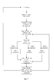
- the execution processes of the main control unit 226 are shown in Fig. 7 .
- the data may be directly transmitted through data transmission without being encoded, which is convenient and prompt.
- the parsing unit 221 and the read unit 224 in the FPGA are realized in the form of hardware, so that they may operate much more efficiently than those in the form of software.
- the computer 25 packages an image to be marked and transfers it to the interface module 21; the interface module 21 transfers all information from the computer 25 to the parsing unit 221; after receiving the information, the parsing unit 221 filters the information; if the information is a marking instructions, then it may be written in the storing unit 223 to buffer; and if the information is control parameters (such as, the power of marking, the speed of marking, and the like), the control parameters may be written in the instruction registering unit 222 according to the protocol. After all information is completely written in, the first step of transferring information is finished.
- the computer 25 writes a start command of starting marking into the instruction registering unit 222; once the main control unit 226 detects the start command, it may request the read unit to read the marking instructions from the storing unit 223 and buffer the marking instructions in the instruction registering unit 225 which is able to buffer 500 instructions so as to keep the main control unit 226 not in vacancy; the main control unit 226 reads the marking instructions from the instruction registering unit 225 and parses the marking instructions; and according to the parsed information, the main control unit 226 transfers the switch and delay time information for controlling the laser to the laser control module 23 and transfers a next coordinate point of the galvanometer to the galvanometer control module 24.
- the laser control module 23 may control the switch of the laser device according to the received information, and the galvanometer control module 24 may determine a movement position of the galvanometer for each step according to the received parameters until the target coordinate point is reached.
- the buffer space between the main control unit 226 and the instruction registering unit 225 is empty.
- the marking is finished, and the second step is terminated.
- the instruction registering unit 222 may be a register, and a plurality of registers may be provided.
- the present invention has at least following advantages. Firstly, the laser marking machine in the prior art is divided into a marking board and a laser device, both of which are combined to control the switch of laser; the marking board converts the control signal to a db25 high-low level signal; the laser device detects the db25 high-low level signal and parse the detected signal to obtain a signal for control the laser; and the whole process is a process of encode-transit-decode, and the calculation of encoding and decoding may possibly induce errors.
- the laser marking machine in the present invention transfers the laser control parameters completely through the instruction registering unit and the storing unit, whereby omitting the process of encode-transit-decode and omitting the db25 interface. Therefore, the first advantage is properly improved.
- the laser marking machine in the present invention integrates the marking board and the laser device; and the laser marking machine in the present invention has a high integration from inside control logic to outside structural arrangement, whereby saving space and lowering consumption.
- the marking logic may control the laser more flexibly and easily. Since the control of the laser is not based on the simple db25 but depends on the instruction registering unit and the storing unit, the control is more appropriate and exact.
- the parsing module may parse the received marking data packets to obtain the marking instructions and the control parameters; the main control unit may execute according to the marking instructions and the control parameters to obtain the laser control instruction(s), the galvanometer control instruction(s), the laser control parameter(s) and the galvanometer control parameter(s); wherein, the main control unit may directly transfer the laser control instruction(s) and the laser control parameter(s) to the laser control module and transfer the galvanometer control instruction(s) and the galvanometer control parameter(s) to the galvanometer control module; and the laser control module may directly use the received laser control instruction(s) and laser control parameter(s) upon the receipt, and similarly, the galvanometer control module may also directly use the received galvanometer control instruction(s) and galvanometer control parameter(s) upon the receipt, without encoding and decoding the laser control instruction(s), the galvanometer control instruction(s), the laser control parameter(s) and the galvanometer control parameter(s) during the transmission of the data, which is very
- the present invention also provides a laser output device, which includes the interface module, the processing module, the laser control module and the galvanometer control module of the above embodiments, wherein, the interface module is further configured to convert USB protocol and level signals between the computer and a FPGA; and the processing module, the laser control module and the galvanometer control module are all programs of the FPGA.
- the present invention also provides an implementation of a method for controlling a laser marking machine. Please refer to Fig. 8 .
- Step S401 receiving marking data packets.
- the marking data packets may be transferred by a computer.
- the computer may package a pattern to be marked to the marking data packets, and transfer the marking data packets to the laser marking machine.
- Step S402 parsing the marking data packet to obtain marking instructions and control parameters.
- a laser device used for laser marking may be arranged on a galvanometer, and marking positions of the laser device may be moved by the galvanometer.
- the marking instructions usually include three actions, which include activating the laser device, terminating the laser device and moving the marking positions of the laser device.
- the control parameters may be used to indicate laser power for the laser marking, laser frequency for the laser marking, delay time of activating the laser, delay time of terminating the laser and target coordinate of the movement of the galvanometer, and the like.
- the laser control instructions may include activation of the laser and termination of the laser
- the laser control parameters may include delay time of activating the laser, delay time of terminating the laser, frequency of the laser and power of the laser.
- the galvanometer control instructions may include a coordinate value of the movement of the galvanometer, and the galvanometer control parameters may include velocity of the movement of the galvanometer.
- a start registering sub-unit may be provided.
- the start registering sub-unit may be configured to store a start tag of starting marking and a termination tag of terminating marking.
- the computer may write the start tag in the start registering sub-unit; when it is requested to terminate marking, the computer may write the termination tag in the start registering sub-unit.
- the main control unit may detect the start registering sub-unit. When the start tag is detected, the marking instructions and the control parameters may be read to execute.
- Step S405 executing according to the marking instructions and the control parameters, to obtain laser control instruction(s) and galvanometer control instruction(s) from the marking instructions, and to obtain laser control parameter(s) and galvanometer control parameter(s) from the control parameters.
- the laser control instructions may include activation of the laser and termination of the laser; the laser control parameters may include delay time of activating the laser, delay time of terminating the laser, power of the laser and frequency of the laser; the galvanometer control instructions may include the movement of the galvanometer; and the galvanometer control parameters may include the coordinate of the movement.
- Step S406 directly transferring the laser control instruction(s) and the laser control parameter(s) to the laser control module, such that the laser control module controls the marking of the laser device according to the laser control instruction(s) and the laser control parameter(s); and directly transferring the galvanometer control instruction(s) and the galvanometer control parameter(s) to the galvanometer control module, such that the galvanometer control module controls the movement of the galvanometer according to the galvanometer control instruction(s) and the galvanometer control parameter(s).
- the laser control instruction(s) and the laser control parameter(s) are directly transferred to the laser control module, without transferring the laser control instruction(s) and the laser control parameter(s) after encoding.
- the galvanometer control instruction(s) and the galvanometer control parameter(s) are directly transferred to the galvanometer control module, without transferring the galvanometer control instruction(s) and the galvanometer control parameter(s) after encoding. Since it is not necessary to transfer the galvanometer control instruction(s), the galvanometer control parameter(s), the laser control instruction(s) and the laser control parameter(s) after encoding, the solution of the present invention may not induce calculation errors and may not result in unstable transmission.
- Step S401 and the Step S405 there may be included steps of:
- the instruction registering unit may be a register, and a plurality of registers may be provided such that the control parameters could be stored in different registers according the protocol.
- Step S404 extracting the marking instructions from the storing unit, and extracting the control parameters from the instruction registering unit.
- the read unit 224 may read instructions from the storing unit 223.
- One marking instruction extraction from the storing unit is followed by one marking instruction reduction from the storing unit. After the marking instructions in the buffer unit 225 are all extracted, it means the completion of marking.
- the received marking data packets are parsed to obtain the marking instructions and the control parameters, and execute according to the marking instructions and the control parameters to obtain the laser control instruction(s), the galvanometer control instruction(s), the laser control parameter(s) and the galvanometer control parameter(s); wherein, the laser control instruction(s) and the laser control parameter(s) may be directly transferred to the laser control module, and the galvanometer control instruction(s) and the galvanometer control parameter(s) may be directly transferred to the galvanometer control module; and the laser control module may directly use the received laser control instruction(s) and the laser control parameter(s), and the galvanometer control module may also directly use the received galvanometer control instruction(s) and the galvanometer control parameter(s), without encoding and decoding the laser control instruction(s), the galvanometer control instruction(s), the laser control parameter(s) and the galvanometer control parameter(s) during the transmission of the data, which is very convenient.
- Embodiment of each component of the present invention can be implemented by hardware, or realized by software modules running on one or more processors, or realized by the combination thereof.
- a person skilled in the art should understand that a microprocessor or a digital signal processor (DSP) may be used in practical use to realize some or all the functions of some or all the members of laser marking machine according to the embodiments of the present invention.
- the present invention may be further realized as some or all the equipment or device programs for executing the methods described herein (for example, computer programs and computer program products).
- This program for realizing the present invention may be stored in computer readable medium, or have one or more signal forms. These signals may be downloaded from the Internet website, or be provided by carrying signals, or be provided in any other manners.
Landscapes
- Engineering & Computer Science (AREA)
- Physics & Mathematics (AREA)
- Optics & Photonics (AREA)
- Plasma & Fusion (AREA)
- Mechanical Engineering (AREA)
- Laser Beam Processing (AREA)
Priority Applications (1)
| Application Number | Priority Date | Filing Date | Title |
|---|---|---|---|
| PL15155178T PL3025818T3 (pl) | 2014-11-28 | 2015-02-16 | Maszyna do i sposób sterowania maszyną do znakowania laserowego z zastosowaniem pakietowej analizy składni znakowanych danych |
Applications Claiming Priority (1)
| Application Number | Priority Date | Filing Date | Title |
|---|---|---|---|
| CN201410712091.1A CN104385787B (zh) | 2014-11-28 | 2014-11-28 | 一种激光打标机的控制方法及激光打标机 |
Publications (3)
| Publication Number | Publication Date |
|---|---|
| EP3025818A1 true EP3025818A1 (de) | 2016-06-01 |
| EP3025818B1 EP3025818B1 (de) | 2018-04-04 |
| EP3025818B8 EP3025818B8 (de) | 2018-05-16 |
Family
ID=52472231
Family Applications (1)
| Application Number | Title | Priority Date | Filing Date |
|---|---|---|---|
| EP15155178.5A Active EP3025818B8 (de) | 2014-11-28 | 2015-02-16 | Lasermarkierungsmaschine und Verfahren zur Steuerung einer Lasermarkierungsmaschine unter Verwendung von Paketanalyse-Beanhandlung von Daten |
Country Status (6)
| Country | Link |
|---|---|
| US (1) | US9358808B1 (de) |
| EP (1) | EP3025818B8 (de) |
| CN (1) | CN104385787B (de) |
| ES (1) | ES2667724T3 (de) |
| PL (1) | PL3025818T3 (de) |
| WO (1) | WO2016082353A1 (de) |
Families Citing this family (28)
| Publication number | Priority date | Publication date | Assignee | Title |
|---|---|---|---|---|
| CN104985939B (zh) * | 2015-06-25 | 2016-05-25 | 深圳市创鑫激光股份有限公司 | 一种激光打标机控制方法和激光打标机 |
| CN104999814B (zh) * | 2015-07-28 | 2017-08-01 | 深圳泰德激光科技有限公司 | 激光打标控制方法以及振镜式激光打标系统 |
| CN105058989B (zh) * | 2015-09-01 | 2016-11-23 | 武汉嘉铭激光有限公司 | 一种棒材生产线铭牌标记系统及其控制方法 |
| CN105855719B (zh) * | 2016-03-30 | 2018-01-26 | 深圳市创鑫激光股份有限公司 | 一种激光打标机打标方法和装置 |
| US10520929B2 (en) * | 2016-08-31 | 2019-12-31 | Esab Ab | Techniques for implementing universal commands in a welding or cutting system |
| CN107030388A (zh) * | 2017-04-18 | 2017-08-11 | 潍坊科技学院 | 一种机器人激光打标车辆识别代号的控制系统及其方法 |
| CN107264091B (zh) * | 2017-06-22 | 2019-02-15 | 深圳市创鑫激光股份有限公司 | 一种激光打标控制方法、激光打标机及存储介质 |
| CN107672335B (zh) * | 2017-09-28 | 2023-07-21 | 长沙八思量信息技术有限公司 | 激光标记方法、激光标记机及存储介质 |
| CN107671426B (zh) * | 2017-10-23 | 2023-11-03 | 深圳市杰普特光电股份有限公司 | 激光标刻装置及其标刻方法 |
| CN107984092A (zh) * | 2017-12-29 | 2018-05-04 | 江苏金海创科技有限公司 | 一种激光打标网络系统及其方法 |
| CN108338202A (zh) * | 2018-03-30 | 2018-07-31 | 智锐达仪器科技南通有限公司 | 一种牲畜胴体表皮激光灼刻装置 |
| CN108683478B (zh) * | 2018-05-08 | 2020-09-15 | 深圳市创鑫激光股份有限公司 | 激光器与外部设备的通信方法、激光器系统 |
| CN109396117B (zh) * | 2018-09-18 | 2022-03-08 | 镇江长悦光电科技有限公司 | 一种激光清洗设备的控制方法、清洗设备及存储介质 |
| CN109175716B (zh) * | 2018-10-12 | 2021-04-13 | 常州英诺激光科技有限公司 | 激光打标控制方法、装置、计算机设备和存储介质 |
| CN111186215B (zh) * | 2018-11-15 | 2021-01-29 | 苏州苏大维格科技集团股份有限公司 | 一种激光打印系统及其打印方法 |
| CN109849528B (zh) * | 2019-01-21 | 2020-09-22 | 长沙八思量信息技术有限公司 | 激光打标方法、装置及计算机可读存储介质 |
| CN111822868B (zh) * | 2019-04-19 | 2022-06-17 | 大族激光科技产业集团股份有限公司 | 激光飞行打标机、打标系统及打标方法 |
| CN110174864B (zh) * | 2019-05-28 | 2022-03-22 | 苏州创鑫激光科技有限公司 | 激光打标的控制方法、计算机可读存储介质及激光打标机 |
| CN112091434B (zh) * | 2019-06-18 | 2023-03-28 | 广州翔声智能科技有限公司 | 一种激光打标方法及激光打标系统 |
| CN111716016B (zh) * | 2020-06-12 | 2022-03-08 | 大族激光科技产业集团股份有限公司 | 一种激光头控制方法、激光加工方法及激光头控制系统 |
| CN113102901A (zh) * | 2021-04-14 | 2021-07-13 | 武汉锐科光纤激光技术股份有限公司 | 材料加工方法、装置和存储介质及电子设备 |
| CN114985910B (zh) * | 2022-05-26 | 2024-02-06 | 深圳泰德激光技术股份有限公司 | 激光切割设备及其控制方法、控制系统 |
| CN116652392A (zh) * | 2022-05-27 | 2023-08-29 | 武汉帝尔激光科技股份有限公司 | 打标卡控制方法、装置、计算机设备及存储介质 |
| CN115085896B (zh) * | 2022-07-21 | 2022-12-09 | 北京金橙子科技股份有限公司 | 一种振镜控制信号数据与同步触发分离方法、系统及存储介质 |
| CN115319274B (zh) * | 2022-08-04 | 2025-08-26 | 上海柏楚电子科技股份有限公司 | Ifov系统的平台位置预测方法及振镜指令延时补偿 |
| CN115319300B (zh) * | 2022-10-14 | 2023-03-21 | 前海晶方云(深圳)测试设备有限公司 | 基板打标设备 |
| CN115870629B (zh) * | 2023-02-21 | 2023-05-16 | 飞天诚信科技股份有限公司 | 一种单线字体的激光刻字方法、装置、设备和介质 |
| CN117583761B (zh) * | 2024-01-19 | 2024-03-19 | 深圳市智鼎自动化技术有限公司 | 一种多通道激光振镜运动控制系统 |
Citations (4)
| Publication number | Priority date | Publication date | Assignee | Title |
|---|---|---|---|---|
| US20050108502A1 (en) * | 2003-10-10 | 2005-05-19 | Nokia Corporation | Microcontrol architecture for a system on a chip (SoC) |
| US20070100492A1 (en) * | 2005-10-21 | 2007-05-03 | Mamoru Idaka | Three dimensional processing data setting system, method for setting three-dimensional processing data, computer program for setting three-dimensional processing data, medium with three-dimensional processing data stored therein that is readable by computer and laser processing equipment operated by the three-dimensional data |
| US20110045835A1 (en) * | 2009-08-21 | 2011-02-24 | Joey Chou | Self-configuration of femtocell access points (fap) |
| US20120293642A1 (en) * | 2011-05-18 | 2012-11-22 | Nextgenid, Inc. | Multi-biometric enrollment kiosk including biometric enrollment and verification, face recognition and fingerprint matching systems |
Family Cites Families (6)
| Publication number | Priority date | Publication date | Assignee | Title |
|---|---|---|---|---|
| DE19727957A1 (de) * | 1996-07-02 | 1998-01-08 | Miyachi Technos Kk | Lasermarkiervorrichtung vom Abtasttyp |
| CN101017424A (zh) * | 2006-11-24 | 2007-08-15 | 华中科技大学 | 基于usb接口的打标控制器 |
| CN101104239B (zh) * | 2007-07-30 | 2010-10-20 | 武昌船舶重工有限责任公司 | 数控切割控制装置及数控切割控制方法 |
| CN102205469A (zh) * | 2010-03-31 | 2011-10-05 | 深圳市先阳软件技术有限公司 | 一种对电池极片进行激光切割的控制方法及系统 |
| CN102381060A (zh) * | 2010-08-30 | 2012-03-21 | 深圳市大族激光科技股份有限公司 | 一种激光打标控制卡及激光打标机 |
| CN103072383B (zh) * | 2011-10-26 | 2015-08-05 | 大族激光科技产业集团股份有限公司 | 一种振镜式激光打标机及其打标控制卡 |
-
2014
- 2014-11-28 CN CN201410712091.1A patent/CN104385787B/zh active Active
-
2015
- 2015-02-12 WO PCT/CN2015/072850 patent/WO2016082353A1/zh not_active Ceased
- 2015-02-13 US US14/621,397 patent/US9358808B1/en active Active
- 2015-02-16 PL PL15155178T patent/PL3025818T3/pl unknown
- 2015-02-16 ES ES15155178.5T patent/ES2667724T3/es active Active
- 2015-02-16 EP EP15155178.5A patent/EP3025818B8/de active Active
Patent Citations (4)
| Publication number | Priority date | Publication date | Assignee | Title |
|---|---|---|---|---|
| US20050108502A1 (en) * | 2003-10-10 | 2005-05-19 | Nokia Corporation | Microcontrol architecture for a system on a chip (SoC) |
| US20070100492A1 (en) * | 2005-10-21 | 2007-05-03 | Mamoru Idaka | Three dimensional processing data setting system, method for setting three-dimensional processing data, computer program for setting three-dimensional processing data, medium with three-dimensional processing data stored therein that is readable by computer and laser processing equipment operated by the three-dimensional data |
| US20110045835A1 (en) * | 2009-08-21 | 2011-02-24 | Joey Chou | Self-configuration of femtocell access points (fap) |
| US20120293642A1 (en) * | 2011-05-18 | 2012-11-22 | Nextgenid, Inc. | Multi-biometric enrollment kiosk including biometric enrollment and verification, face recognition and fingerprint matching systems |
Also Published As
| Publication number | Publication date |
|---|---|
| PL3025818T3 (pl) | 2018-07-31 |
| CN104385787B (zh) | 2015-08-12 |
| ES2667724T3 (es) | 2018-05-14 |
| CN104385787A (zh) | 2015-03-04 |
| WO2016082353A1 (zh) | 2016-06-02 |
| US20160152040A1 (en) | 2016-06-02 |
| EP3025818B8 (de) | 2018-05-16 |
| EP3025818B1 (de) | 2018-04-04 |
| US9358808B1 (en) | 2016-06-07 |
Similar Documents
| Publication | Publication Date | Title |
|---|---|---|
| EP3025818B1 (de) | Lasermarkierungsmaschine und Verfahren zur Steuerung einer Lasermarkierungsmaschine unter Verwendung von Paketanalyse-Beanhandlung von Daten | |
| CN102075389B (zh) | 一种调试方法和设备 | |
| CN114297124B (zh) | 一种基于fpga的srio高速总线的通讯系统 | |
| CN101917316A (zh) | 一种高速实时工业以太网的通信方法及装置 | |
| EP3444080B1 (de) | Aktuatorsteuerungssystem, aktuatorsteuerungsverfahren, informationsverarbeitungsprogramm und aufzeichnungsmedium | |
| EP3200089B1 (de) | Verfahren, vorrichtung, kommunikationsausrüstung und speichermedien zur bestimmung einer verbindungsverzögerung | |
| JP2021536051A5 (de) | ||
| CN104985939B (zh) | 一种激光打标机控制方法和激光打标机 | |
| CN114327975B (zh) | 片上系统 | |
| CN117118828B (zh) | 一种协议转换器、电子设备及一种配置方法 | |
| TWI681652B (zh) | 介面電路、信號傳輸系統及其信號傳輸方法 | |
| CN104158876A (zh) | 基于Vxworks操作系统的双工件台光刻机控制系统通信装置 | |
| CN102760105B (zh) | 实现本地主从模块间的通信的系统及方法 | |
| KR101593835B1 (ko) | Plc 시스템 | |
| CN104615573A (zh) | 一种通信方法及装置 | |
| US10379518B2 (en) | Numerical control device and control system | |
| CN113722250A (zh) | 基于Aurora协议的双路冗余数据交换方法及系统 | |
| CN118151869A (zh) | 一种打印方法、装置、设备以及存储介质 | |
| TWI425366B (zh) | 根據通訊協定處理來執行資料存取的方法與裝置 | |
| CN106919876A (zh) | 多协议rfid读写器的自适应协议切换方法 | |
| CN101853366B (zh) | 根据通讯协议处理来执行数据存取的方法与装置 | |
| CN109857485B (zh) | 一种可编程gpio装置及基于该装置的时序实现方法 | |
| CN119127751B (zh) | Dma控制器、芯片、根复合体及端点设备 | |
| CN108647178B (zh) | 双通道通信的方法和设备 | |
| CN104809038A (zh) | 一种fifo异常处理方法及装置 |
Legal Events
| Date | Code | Title | Description |
|---|---|---|---|
| PUAI | Public reference made under article 153(3) epc to a published international application that has entered the european phase |
Free format text: ORIGINAL CODE: 0009012 |
|
| 17P | Request for examination filed |
Effective date: 20150216 |
|
| AK | Designated contracting states |
Kind code of ref document: A1 Designated state(s): AL AT BE BG CH CY CZ DE DK EE ES FI FR GB GR HR HU IE IS IT LI LT LU LV MC MK MT NL NO PL PT RO RS SE SI SK SM TR |
|
| AX | Request for extension of the european patent |
Extension state: BA ME |
|
| 17Q | First examination report despatched |
Effective date: 20160622 |
|
| STAA | Information on the status of an ep patent application or granted ep patent |
Free format text: STATUS: EXAMINATION IS IN PROGRESS |
|
| GRAP | Despatch of communication of intention to grant a patent |
Free format text: ORIGINAL CODE: EPIDOSNIGR1 |
|
| STAA | Information on the status of an ep patent application or granted ep patent |
Free format text: STATUS: GRANT OF PATENT IS INTENDED |
|
| INTG | Intention to grant announced |
Effective date: 20171025 |
|
| GRAS | Grant fee paid |
Free format text: ORIGINAL CODE: EPIDOSNIGR3 |
|
| GRAA | (expected) grant |
Free format text: ORIGINAL CODE: 0009210 |
|
| STAA | Information on the status of an ep patent application or granted ep patent |
Free format text: STATUS: THE PATENT HAS BEEN GRANTED |
|
| GRAT | Correction requested after decision to grant or after decision to maintain patent in amended form |
Free format text: ORIGINAL CODE: EPIDOSNCDEC |
|
| AK | Designated contracting states |
Kind code of ref document: B1 Designated state(s): AL AT BE BG CH CY CZ DE DK EE ES FI FR GB GR HR HU IE IS IT LI LT LU LV MC MK MT NL NO PL PT RO RS SE SI SK SM TR |
|
| REG | Reference to a national code |
Ref country code: GB Ref legal event code: FG4D |
|
| REG | Reference to a national code |
Ref country code: CH Ref legal event code: EP |
|
| REG | Reference to a national code |
Ref country code: AT Ref legal event code: REF Ref document number: 985075 Country of ref document: AT Kind code of ref document: T Effective date: 20180415 |
|
| REG | Reference to a national code |
Ref country code: IE Ref legal event code: FG4D |
|
| REG | Reference to a national code |
Ref country code: DE Ref legal event code: R096 Ref document number: 602015009423 Country of ref document: DE |
|
| REG | Reference to a national code |
Ref country code: ES Ref legal event code: FG2A Ref document number: 2667724 Country of ref document: ES Kind code of ref document: T3 Effective date: 20180514 |
|
| REG | Reference to a national code |
Ref country code: NL Ref legal event code: MP Effective date: 20180404 |
|
| REG | Reference to a national code |
Ref country code: LT Ref legal event code: MG4D |
|
| PG25 | Lapsed in a contracting state [announced via postgrant information from national office to epo] |
Ref country code: NL Free format text: LAPSE BECAUSE OF FAILURE TO SUBMIT A TRANSLATION OF THE DESCRIPTION OR TO PAY THE FEE WITHIN THE PRESCRIBED TIME-LIMIT Effective date: 20180404 |
|
| PG25 | Lapsed in a contracting state [announced via postgrant information from national office to epo] |
Ref country code: LT Free format text: LAPSE BECAUSE OF FAILURE TO SUBMIT A TRANSLATION OF THE DESCRIPTION OR TO PAY THE FEE WITHIN THE PRESCRIBED TIME-LIMIT Effective date: 20180404 Ref country code: SE Free format text: LAPSE BECAUSE OF FAILURE TO SUBMIT A TRANSLATION OF THE DESCRIPTION OR TO PAY THE FEE WITHIN THE PRESCRIBED TIME-LIMIT Effective date: 20180404 Ref country code: NO Free format text: LAPSE BECAUSE OF FAILURE TO SUBMIT A TRANSLATION OF THE DESCRIPTION OR TO PAY THE FEE WITHIN THE PRESCRIBED TIME-LIMIT Effective date: 20180704 Ref country code: AL Free format text: LAPSE BECAUSE OF FAILURE TO SUBMIT A TRANSLATION OF THE DESCRIPTION OR TO PAY THE FEE WITHIN THE PRESCRIBED TIME-LIMIT Effective date: 20180404 Ref country code: FI Free format text: LAPSE BECAUSE OF FAILURE TO SUBMIT A TRANSLATION OF THE DESCRIPTION OR TO PAY THE FEE WITHIN THE PRESCRIBED TIME-LIMIT Effective date: 20180404 Ref country code: BG Free format text: LAPSE BECAUSE OF FAILURE TO SUBMIT A TRANSLATION OF THE DESCRIPTION OR TO PAY THE FEE WITHIN THE PRESCRIBED TIME-LIMIT Effective date: 20180704 |
|
| PG25 | Lapsed in a contracting state [announced via postgrant information from national office to epo] |
Ref country code: RS Free format text: LAPSE BECAUSE OF FAILURE TO SUBMIT A TRANSLATION OF THE DESCRIPTION OR TO PAY THE FEE WITHIN THE PRESCRIBED TIME-LIMIT Effective date: 20180404 Ref country code: LV Free format text: LAPSE BECAUSE OF FAILURE TO SUBMIT A TRANSLATION OF THE DESCRIPTION OR TO PAY THE FEE WITHIN THE PRESCRIBED TIME-LIMIT Effective date: 20180404 Ref country code: HR Free format text: LAPSE BECAUSE OF FAILURE TO SUBMIT A TRANSLATION OF THE DESCRIPTION OR TO PAY THE FEE WITHIN THE PRESCRIBED TIME-LIMIT Effective date: 20180404 Ref country code: GR Free format text: LAPSE BECAUSE OF FAILURE TO SUBMIT A TRANSLATION OF THE DESCRIPTION OR TO PAY THE FEE WITHIN THE PRESCRIBED TIME-LIMIT Effective date: 20180705 |
|
| REG | Reference to a national code |
Ref country code: AT Ref legal event code: MK05 Ref document number: 985075 Country of ref document: AT Kind code of ref document: T Effective date: 20180404 |
|
| PG25 | Lapsed in a contracting state [announced via postgrant information from national office to epo] |
Ref country code: PT Free format text: LAPSE BECAUSE OF FAILURE TO SUBMIT A TRANSLATION OF THE DESCRIPTION OR TO PAY THE FEE WITHIN THE PRESCRIBED TIME-LIMIT Effective date: 20180806 |
|
| REG | Reference to a national code |
Ref country code: DE Ref legal event code: R097 Ref document number: 602015009423 Country of ref document: DE |
|
| PG25 | Lapsed in a contracting state [announced via postgrant information from national office to epo] |
Ref country code: AT Free format text: LAPSE BECAUSE OF FAILURE TO SUBMIT A TRANSLATION OF THE DESCRIPTION OR TO PAY THE FEE WITHIN THE PRESCRIBED TIME-LIMIT Effective date: 20180404 Ref country code: EE Free format text: LAPSE BECAUSE OF FAILURE TO SUBMIT A TRANSLATION OF THE DESCRIPTION OR TO PAY THE FEE WITHIN THE PRESCRIBED TIME-LIMIT Effective date: 20180404 Ref country code: DK Free format text: LAPSE BECAUSE OF FAILURE TO SUBMIT A TRANSLATION OF THE DESCRIPTION OR TO PAY THE FEE WITHIN THE PRESCRIBED TIME-LIMIT Effective date: 20180404 Ref country code: SK Free format text: LAPSE BECAUSE OF FAILURE TO SUBMIT A TRANSLATION OF THE DESCRIPTION OR TO PAY THE FEE WITHIN THE PRESCRIBED TIME-LIMIT Effective date: 20180404 Ref country code: RO Free format text: LAPSE BECAUSE OF FAILURE TO SUBMIT A TRANSLATION OF THE DESCRIPTION OR TO PAY THE FEE WITHIN THE PRESCRIBED TIME-LIMIT Effective date: 20180404 |
|
| PLBE | No opposition filed within time limit |
Free format text: ORIGINAL CODE: 0009261 |
|
| STAA | Information on the status of an ep patent application or granted ep patent |
Free format text: STATUS: NO OPPOSITION FILED WITHIN TIME LIMIT |
|
| PG25 | Lapsed in a contracting state [announced via postgrant information from national office to epo] |
Ref country code: SM Free format text: LAPSE BECAUSE OF FAILURE TO SUBMIT A TRANSLATION OF THE DESCRIPTION OR TO PAY THE FEE WITHIN THE PRESCRIBED TIME-LIMIT Effective date: 20180404 Ref country code: IT Free format text: LAPSE BECAUSE OF FAILURE TO SUBMIT A TRANSLATION OF THE DESCRIPTION OR TO PAY THE FEE WITHIN THE PRESCRIBED TIME-LIMIT Effective date: 20180404 |
|
| 26N | No opposition filed |
Effective date: 20190107 |
|
| PG25 | Lapsed in a contracting state [announced via postgrant information from national office to epo] |
Ref country code: SI Free format text: LAPSE BECAUSE OF FAILURE TO SUBMIT A TRANSLATION OF THE DESCRIPTION OR TO PAY THE FEE WITHIN THE PRESCRIBED TIME-LIMIT Effective date: 20180404 |
|
| REG | Reference to a national code |
Ref country code: CH Ref legal event code: PL |
|
| GBPC | Gb: european patent ceased through non-payment of renewal fee |
Effective date: 20190216 |
|
| PG25 | Lapsed in a contracting state [announced via postgrant information from national office to epo] |
Ref country code: LU Free format text: LAPSE BECAUSE OF NON-PAYMENT OF DUE FEES Effective date: 20190216 Ref country code: MC Free format text: LAPSE BECAUSE OF FAILURE TO SUBMIT A TRANSLATION OF THE DESCRIPTION OR TO PAY THE FEE WITHIN THE PRESCRIBED TIME-LIMIT Effective date: 20180404 |
|
| REG | Reference to a national code |
Ref country code: BE Ref legal event code: MM Effective date: 20190228 |
|
| REG | Reference to a national code |
Ref country code: IE Ref legal event code: MM4A |
|
| PG25 | Lapsed in a contracting state [announced via postgrant information from national office to epo] |
Ref country code: LI Free format text: LAPSE BECAUSE OF NON-PAYMENT OF DUE FEES Effective date: 20190228 Ref country code: CH Free format text: LAPSE BECAUSE OF NON-PAYMENT OF DUE FEES Effective date: 20190228 |
|
| PG25 | Lapsed in a contracting state [announced via postgrant information from national office to epo] |
Ref country code: IE Free format text: LAPSE BECAUSE OF NON-PAYMENT OF DUE FEES Effective date: 20190216 Ref country code: GB Free format text: LAPSE BECAUSE OF NON-PAYMENT OF DUE FEES Effective date: 20190216 |
|
| PG25 | Lapsed in a contracting state [announced via postgrant information from national office to epo] |
Ref country code: FR Free format text: LAPSE BECAUSE OF NON-PAYMENT OF DUE FEES Effective date: 20190228 Ref country code: BE Free format text: LAPSE BECAUSE OF NON-PAYMENT OF DUE FEES Effective date: 20190228 |
|
| PG25 | Lapsed in a contracting state [announced via postgrant information from national office to epo] |
Ref country code: MT Free format text: LAPSE BECAUSE OF NON-PAYMENT OF DUE FEES Effective date: 20190216 |
|
| PG25 | Lapsed in a contracting state [announced via postgrant information from national office to epo] |
Ref country code: CY Free format text: LAPSE BECAUSE OF FAILURE TO SUBMIT A TRANSLATION OF THE DESCRIPTION OR TO PAY THE FEE WITHIN THE PRESCRIBED TIME-LIMIT Effective date: 20180404 |
|
| PG25 | Lapsed in a contracting state [announced via postgrant information from national office to epo] |
Ref country code: IS Free format text: LAPSE BECAUSE OF FAILURE TO SUBMIT A TRANSLATION OF THE DESCRIPTION OR TO PAY THE FEE WITHIN THE PRESCRIBED TIME-LIMIT Effective date: 20180804 |
|
| PG25 | Lapsed in a contracting state [announced via postgrant information from national office to epo] |
Ref country code: HU Free format text: LAPSE BECAUSE OF FAILURE TO SUBMIT A TRANSLATION OF THE DESCRIPTION OR TO PAY THE FEE WITHIN THE PRESCRIBED TIME-LIMIT; INVALID AB INITIO Effective date: 20150216 |
|
| PG25 | Lapsed in a contracting state [announced via postgrant information from national office to epo] |
Ref country code: MK Free format text: LAPSE BECAUSE OF FAILURE TO SUBMIT A TRANSLATION OF THE DESCRIPTION OR TO PAY THE FEE WITHIN THE PRESCRIBED TIME-LIMIT Effective date: 20180404 |
|
| PGFP | Annual fee paid to national office [announced via postgrant information from national office to epo] |
Ref country code: ES Payment date: 20260309 Year of fee payment: 12 |
|
| PGFP | Annual fee paid to national office [announced via postgrant information from national office to epo] |
Ref country code: DE Payment date: 20260206 Year of fee payment: 12 |
|
| PGFP | Annual fee paid to national office [announced via postgrant information from national office to epo] |
Ref country code: TR Payment date: 20260213 Year of fee payment: 12 |
|
| PGFP | Annual fee paid to national office [announced via postgrant information from national office to epo] |
Ref country code: CZ Payment date: 20260130 Year of fee payment: 12 |
|
| PGFP | Annual fee paid to national office [announced via postgrant information from national office to epo] |
Ref country code: PL Payment date: 20260119 Year of fee payment: 12 |