EP3023717B1 - Refrigerator - Google Patents
Refrigerator Download PDFInfo
- Publication number
- EP3023717B1 EP3023717B1 EP15189499.5A EP15189499A EP3023717B1 EP 3023717 B1 EP3023717 B1 EP 3023717B1 EP 15189499 A EP15189499 A EP 15189499A EP 3023717 B1 EP3023717 B1 EP 3023717B1
- Authority
- EP
- European Patent Office
- Prior art keywords
- storage compartment
- guide
- temperature
- cold air
- refrigerator according
- Prior art date
- Legal status (The legal status is an assumption and is not a legal conclusion. Google has not performed a legal analysis and makes no representation as to the accuracy of the status listed.)
- Active
Links
- 239000012782 phase change material Substances 0.000 claims description 55
- 238000009413 insulation Methods 0.000 claims description 37
- 238000002844 melting Methods 0.000 claims description 11
- 230000008018 melting Effects 0.000 claims description 11
- 239000003507 refrigerant Substances 0.000 claims description 9
- 229920001903 high density polyethylene Polymers 0.000 claims description 5
- 239000004700 high-density polyethylene Substances 0.000 claims description 5
- 230000008878 coupling Effects 0.000 claims description 2
- 238000010168 coupling process Methods 0.000 claims description 2
- 238000005859 coupling reaction Methods 0.000 claims description 2
- 230000035515 penetration Effects 0.000 claims description 2
- 238000007710 freezing Methods 0.000 description 6
- 230000008014 freezing Effects 0.000 description 6
- 239000007791 liquid phase Substances 0.000 description 6
- 238000005057 refrigeration Methods 0.000 description 6
- 239000012071 phase Substances 0.000 description 5
- 230000005494 condensation Effects 0.000 description 4
- 238000009833 condensation Methods 0.000 description 4
- 238000001816 cooling Methods 0.000 description 4
- 239000007790 solid phase Substances 0.000 description 4
- 230000003111 delayed effect Effects 0.000 description 3
- 230000008859 change Effects 0.000 description 2
- 238000004891 communication Methods 0.000 description 2
- 238000010586 diagram Methods 0.000 description 2
- 230000000977 initiatory effect Effects 0.000 description 2
- 239000000463 material Substances 0.000 description 2
- 239000002826 coolant Substances 0.000 description 1
- 230000001747 exhibiting effect Effects 0.000 description 1
- 239000012530 fluid Substances 0.000 description 1
- 230000005484 gravity Effects 0.000 description 1
- 238000005338 heat storage Methods 0.000 description 1
- 238000009434 installation Methods 0.000 description 1
- 239000007788 liquid Substances 0.000 description 1
- 230000007246 mechanism Effects 0.000 description 1
- 238000000034 method Methods 0.000 description 1
- 238000012986 modification Methods 0.000 description 1
- 230000004048 modification Effects 0.000 description 1
- 230000008569 process Effects 0.000 description 1
- 230000035939 shock Effects 0.000 description 1
- 239000000126 substance Substances 0.000 description 1
Images


Classifications
-
- F—MECHANICAL ENGINEERING; LIGHTING; HEATING; WEAPONS; BLASTING
- F25—REFRIGERATION OR COOLING; COMBINED HEATING AND REFRIGERATION SYSTEMS; HEAT PUMP SYSTEMS; MANUFACTURE OR STORAGE OF ICE; LIQUEFACTION SOLIDIFICATION OF GASES
- F25D—REFRIGERATORS; COLD ROOMS; ICE-BOXES; COOLING OR FREEZING APPARATUS NOT OTHERWISE PROVIDED FOR
- F25D17/00—Arrangements for circulating cooling fluids; Arrangements for circulating gas, e.g. air, within refrigerated spaces
- F25D17/04—Arrangements for circulating cooling fluids; Arrangements for circulating gas, e.g. air, within refrigerated spaces for circulating air, e.g. by convection
- F25D17/06—Arrangements for circulating cooling fluids; Arrangements for circulating gas, e.g. air, within refrigerated spaces for circulating air, e.g. by convection by forced circulation
- F25D17/062—Arrangements for circulating cooling fluids; Arrangements for circulating gas, e.g. air, within refrigerated spaces for circulating air, e.g. by convection by forced circulation in household refrigerators
-
- F—MECHANICAL ENGINEERING; LIGHTING; HEATING; WEAPONS; BLASTING
- F25—REFRIGERATION OR COOLING; COMBINED HEATING AND REFRIGERATION SYSTEMS; HEAT PUMP SYSTEMS; MANUFACTURE OR STORAGE OF ICE; LIQUEFACTION SOLIDIFICATION OF GASES
- F25D—REFRIGERATORS; COLD ROOMS; ICE-BOXES; COOLING OR FREEZING APPARATUS NOT OTHERWISE PROVIDED FOR
- F25D17/00—Arrangements for circulating cooling fluids; Arrangements for circulating gas, e.g. air, within refrigerated spaces
- F25D17/04—Arrangements for circulating cooling fluids; Arrangements for circulating gas, e.g. air, within refrigerated spaces for circulating air, e.g. by convection
- F25D17/06—Arrangements for circulating cooling fluids; Arrangements for circulating gas, e.g. air, within refrigerated spaces for circulating air, e.g. by convection by forced circulation
- F25D17/08—Arrangements for circulating cooling fluids; Arrangements for circulating gas, e.g. air, within refrigerated spaces for circulating air, e.g. by convection by forced circulation using ducts
-
- F—MECHANICAL ENGINEERING; LIGHTING; HEATING; WEAPONS; BLASTING
- F25—REFRIGERATION OR COOLING; COMBINED HEATING AND REFRIGERATION SYSTEMS; HEAT PUMP SYSTEMS; MANUFACTURE OR STORAGE OF ICE; LIQUEFACTION SOLIDIFICATION OF GASES
- F25D—REFRIGERATORS; COLD ROOMS; ICE-BOXES; COOLING OR FREEZING APPARATUS NOT OTHERWISE PROVIDED FOR
- F25D11/00—Self-contained movable devices, e.g. domestic refrigerators
- F25D11/006—Self-contained movable devices, e.g. domestic refrigerators with cold storage accumulators
-
- F—MECHANICAL ENGINEERING; LIGHTING; HEATING; WEAPONS; BLASTING
- F25—REFRIGERATION OR COOLING; COMBINED HEATING AND REFRIGERATION SYSTEMS; HEAT PUMP SYSTEMS; MANUFACTURE OR STORAGE OF ICE; LIQUEFACTION SOLIDIFICATION OF GASES
- F25D—REFRIGERATORS; COLD ROOMS; ICE-BOXES; COOLING OR FREEZING APPARATUS NOT OTHERWISE PROVIDED FOR
- F25D11/00—Self-contained movable devices, e.g. domestic refrigerators
- F25D11/02—Self-contained movable devices, e.g. domestic refrigerators with cooling compartments at different temperatures
-
- F—MECHANICAL ENGINEERING; LIGHTING; HEATING; WEAPONS; BLASTING
- F25—REFRIGERATION OR COOLING; COMBINED HEATING AND REFRIGERATION SYSTEMS; HEAT PUMP SYSTEMS; MANUFACTURE OR STORAGE OF ICE; LIQUEFACTION SOLIDIFICATION OF GASES
- F25D—REFRIGERATORS; COLD ROOMS; ICE-BOXES; COOLING OR FREEZING APPARATUS NOT OTHERWISE PROVIDED FOR
- F25D17/00—Arrangements for circulating cooling fluids; Arrangements for circulating gas, e.g. air, within refrigerated spaces
- F25D17/04—Arrangements for circulating cooling fluids; Arrangements for circulating gas, e.g. air, within refrigerated spaces for circulating air, e.g. by convection
- F25D17/06—Arrangements for circulating cooling fluids; Arrangements for circulating gas, e.g. air, within refrigerated spaces for circulating air, e.g. by convection by forced circulation
-
- F—MECHANICAL ENGINEERING; LIGHTING; HEATING; WEAPONS; BLASTING
- F25—REFRIGERATION OR COOLING; COMBINED HEATING AND REFRIGERATION SYSTEMS; HEAT PUMP SYSTEMS; MANUFACTURE OR STORAGE OF ICE; LIQUEFACTION SOLIDIFICATION OF GASES
- F25D—REFRIGERATORS; COLD ROOMS; ICE-BOXES; COOLING OR FREEZING APPARATUS NOT OTHERWISE PROVIDED FOR
- F25D2317/00—Details or arrangements for circulating cooling fluids; Details or arrangements for circulating gas, e.g. air, within refrigerated spaces, not provided for in other groups of this subclass
- F25D2317/06—Details or arrangements for circulating cooling fluids; Details or arrangements for circulating gas, e.g. air, within refrigerated spaces, not provided for in other groups of this subclass with forced air circulation
- F25D2317/067—Details or arrangements for circulating cooling fluids; Details or arrangements for circulating gas, e.g. air, within refrigerated spaces, not provided for in other groups of this subclass with forced air circulation characterised by air ducts
- F25D2317/0672—Outlet ducts
Definitions
- the present invention relates to a refrigerator and, more particularly, to a refrigerator which is improved in terms of power consumption.
- a refrigerator includes a machine room in the lower region of a main body.
- the machine room is generally installed in the lower region of the refrigerator, in consideration of the center of gravity of the refrigerator, easy of assembly, and vibration attenuation.
- a refrigeration cycle device is installed in the machine room of the refrigerator and serves to keep the interior of the refrigerator in a frozen or refrigerated state using the characteristics of a refrigerant which absorbs external heat while varying from a low-pressure liquid state to a gaseous state, thereby realizing the stable storage of fresh food.
- the refrigeration cycle device of the refrigerator includes, for example, a compressor which changes a low-temperature and low-pressure gas phase refrigerant into a high-temperature and high-pressure gas phase refrigerant, a condenser which changes the high-temperature and high-pressure gas phase refrigerant, acquired from the compressor, into a high-temperature and high-pressure liquid phase refrigerant, and an evaporator which absorbs external heat while changing a low-temperature and high-pressure liquid phase refrigerant, acquired from the condenser, into a gas phase refrigerant.
- a compressor which changes a low-temperature and low-pressure gas phase refrigerant into a high-temperature and high-pressure gas phase refrigerant
- a condenser which changes the high-temperature and high-pressure gas phase refrigerant, acquired from the compressor, into a high-temperature and high-pressure liquid phase refrigerant
- an evaporator which absorbs external heat while changing a low-temperature
- a conventional refrigerator exhibits temperature distribution having the highest temperature in the uppermost shelf of a storage compartment.
- the compressor is driven based on the temperature of the upper region of the storage compartment even through the lower region of the storage compartment has a lower temperature than the upper region, which unnecessarily increases power consumption.
- FR 2 778 733 A1 describes a refrigerated vending cabinet.
- the vending cabinet has shelves with double walls through which a coolant fluid is circulated from the back to the front of the shelves.
- the cooling air flowing inside the shelves escapes through openings located at the front of the shelves.
- JP 2013 245842 A describes a refrigerator including a refrigerating chamber, a cooling mechanism for cooling air with constant power consumption during normal operation, and a heat storage member.
- KR 2011 0089575 A discloses a refrigerator according to the preamble of claim 1.
- the present invention is directed to a refrigerator that substantially obviates one or more problems due to limitations and disadvantages of the related art.
- One object of the present invention is to provide a refrigerator which is capable of exhibiting reduced power consumption.
- another object of the present invention is to provide a refrigerator which is capable of achieving even temperature distribution within a storage compartment.
- the guide may undergo heat exchange with the cold air to be discharged to the storage compartment within the duct unit.
- the compressor may supply the cold air having a lower temperature than the melting point of the phase change material, and the cold air, supplied to the storage compartment while the compressor is operated, may be increased in temperature by the guide.
- the storage compartment may be lowered in temperature by the guide while the compressor is not operating.
- the duct unit according to the present invention includes a duct cover configured to be exposed to the storage compartment, a first insulation member attached to the back of the duct cover, and a second insulation member installed to the back of the first insulation member so as to define a space for passage of the cold air between the first insulation member and the second insulation member, and the guide is installed between the first insulation member and the second insulation member.
- the guide may include a tapered portion having an upwardly increasing cross sectional width.
- the guide may include a body charged with the phase change material, and the body may have greater thermal conductivity than the phase change material.
- the body may be formed of HDPE(5200B).
- the body may not be charged in a lower end region thereof with the phase change material, and a guide member having a prescribed volume may be provided in the lower end region of the body.
- the duct cover may be formed with a protrusion, and the first insulation member and the guide may be respectively formed with through-holes for penetration and coupling of the protrusion.
- the discharge holes may be formed in the duct cover and the first insulation member, and the discharge holes may be arranged at opposite sides of the guide interposed therebetween.
- the guide may have a lowermost end located lower than a lowermost one of the discharge holes.
- the storage compartment may be a refrigerating compartment, and the phase change material may have a melting point near 0°C .
- the refrigerator may further include a temperature sensor configured to sense a temperature inside the storage compartment, a fan installed in the duct unit, and a controller configured to drive the fan when the temperature inside the storage compartment is increased to a prescribed temperature or higher.
- the discharge holes may be continuously kept in an open state.
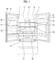
- FIG. 1 is a front view of a refrigerator according to an embodiment of the present invention.
- the refrigerator includes a cabinet 1 which defines the external appearance of the refrigerator.
- the cabinet 1 is provided with a storage compartment 2 in which food may be stored.
- the outer contour of the storage compartment 2 may be defined by an inner case 10 which is provided inside the cabinet 1.
- the inner case 10 may include an upper sidewall 12 and a lower sidewall 14, which form the inner surface of the storage compartment 2.
- the front side of the storage compartment 2 is open to allow a user to access the storage compartment 2 through the open front side of the storage compartment 2.
- the cabinet 1 is provided at the front side thereof with a first door 20, which is pivotably installed to the cabinet 1 and is configured to open or close one side of the storage compartment 2, and a second door 40 which is pivotably installed to the cabinet 1 and is configured to open or close the opposite side of the storage compartment 2. At this time, when the first door 20 and the second door 40 close the front side of the storage compartment 2, the storage compartment 2 may be completely sealed.
- the second door 20 may be provided with a pillar 100, which rotates so as to come into contact with the first door 20.
- the pillar 100 may generally have a cuboidal shape, and may be coupled to the second door 40 so as to be rotatable relative to the second door 40.
- the first door 20 may be provided with a door dike 42, which defines the rear outer contour of the first door 20.
- the second door 40 may be provided with a door dike 22, which defines the rear outer contour of the second door 40.
- Baskets 44 and 24 may be installed to the respective door dikes 42 and 22.
- the baskets 44 and 24 may be configured to store various shapes of food therein.
- the storage compartment 2 may be provided with a first drawer 34, which is located toward the first door 20, and a second drawer 32, which is located toward the second door 40.
- the first drawer 34 and the second drawer 32 may be placed in the same horizontal plane. That is, the first drawer 34 and the second drawer 32 may be located in left and right sides at the same height within the storage compartment 2.
- the first drawer 34 and the second drawer 32 may be pulled out independently of each other.
- a duct unit 200 is provided at the rear wall of the storage compartment 2, i.e. the rear wall of the inner case 10.
- the duct unit 200 may serve as a passage through which cold air, generated by a refrigeration cycle device that includes a compressor 600 installed in a machine room, is supplied to the storage compartment 2.
- a temperature sensor 400 may be installed in the storage compartment 2 to measure the temperature inside the storage compartment 2.
- the temperature inside the storage compartment 2 measured by the temperature sensor 400, rises to a set temperature, which is set either arbitrarily or by the user, the compressor 600 is driven to cool the storage compartment 2 to the set temperature or lower.
- the duct unit 200 may generally extend lengthwise in the direction perpendicular to the longitudinal direction of the cabinet 1. Cold air supplied via the duct unit 200 may be supplied into the storage compartment 2 through a plurality of discharge holes 212 which are provided at different heights inside the storage compartment 2.
- the discharge holes 212 formed at various heights allow the cold air to be discharged at different heights within the storage compartment 2.
- the storage compartment 2 may be a freezing compartment, but alternatively may be a refrigerating compartment.
- cold air which has a higher temperature than that in the freezing compartment, is merely supplied into the storage compartment 2.
- the discharge holes 212 may be open, without the installation of a separate closure member, to provide continuous communication between the storage compartment 2 and the interior of the duct unit 200.
- FIG. 2 is an exploded perspective view illustrating major components according to the embodiment
- FIG. 3 is a detailed view of FIG. 2
- FIG. 4 is a view illustrating the coupled state of some major components according to the embodiment.
- a machine room 5 is formed in the lower region of the cabinet 1 such that, for example, the compressor 600 used to compress a refrigerant is installed in the machine room 5.
- a refrigeration cycle device which includes, for example, a condenser in addition to the compressor 600, may be installed in the machine room 5.
- the duct unit 200 may include a duct cover 210 which is exposed to the storage compartment 2, a first insulation member 220 attached to the back of the duct cover 210, and a second insulation member 240 installed to the back of the first insulation member 220 so as to define a space for the passage of cold air between the first insulation member 220 and the second insulation member 240.
- the front surface of the duct cover 210 may be exposed to the outside of the storage compartment 2.
- the discharge holes 212 are formed in the duct cover 210 such that cold air guided by the duct unit 200 may be supplied to the storage compartment 2 through the discharge holes 212.
- discharge holes 212 formed in the duct cover 210 are arranged at different heights, cold air is supplied to different height regions of the storage compartment 2 while the compressor 600 is driven, which allows the interior of the storage compartment 2 to be evenly cooled to a constant temperature.
- the first insulation member 220 and the second insulation member 240 may have prescribed thicknesses, which are required to prevent the cold air passing through the duct unit 200 from forming condensation due to the temperature difference between the duct unit 200 and the outside of the cabinet 1 or the storage compartment 2 located at the front side of the duct cover 210.
- the temperature of the cold air may be lower than the temperature inside the storage compartment 2.
- the temperature difference between the front side of the duct cover 210 (i.e. the interior of the storage compartment 2) and the rear side of the duct cover 210 (i.e. the interior of the duct unit 200) increases, thus causing condensation.
- first insulation member 220 and the second insulation member 240 may generally have a rectangular column shape in the coupled state thereof.
- the first insulation member 220 is formed with discharge holes 222, which are provided in number and shape equal to the discharge holes 212 formed in the duct cover 210 and are located at positions corresponding to the discharge holes 212 formed in the duct cover 210.
- cold air moved to between the first insulation member 220 and the second insulation member 240, may pass through the discharge holes 222 formed in the first insulation member 220, and may thereafter be supplied to the storage compartment 2 through the discharge holes 212 formed in the duct cover 210.
- the discharge holes 212 and 222 may be located at opposite sides of a guide 230 interposed therebetween. As such, the air, discharged through the discharge holes 212 and 222, may easily undergo heat exchange thanks to the guide 230.
- the guide 230 may be installed between the first insulation member 220 and the second insulation member 240 and serve to guide the cold air passing through between the first insulation member 220 and the second insulation member 240.
- the guide 230 may be received in the duct unit 200 to guide the cold air so that it is discharged to the storage compartment 2.
- the duct cover 210 may be formed with a discharge port 214, which protrudes toward the rear surface of the duct cover 210, and the first insulation member 220 and the guide 230 may be formed with respective through-holes 224 and 234, through which the discharge port 214 penetrates and is coupled.
- the discharge port 214 is inserted into and coupled to the through-holes 224 and 234, the duct cover 210, the first insulation member 220, and the guide 230 may be easily positioned at desired positions so as to be coupled into a single member.
- the guide 230 is generally oriented lengthwise in the height direction of the duct unit 200, but is shaped such that no structure is provided at the lower end thereof.
- the guide 230 may function to guide the cold air, which moves from the bottom to the top of the duct unit 200, so that the cold air is divided into opposite directions.
- the duct unit 200 may evenly discharge the cold air, introduced from the lower side thereof, through the discharge holes 212 that are formed in the duct cover 210 at different heights.
- the guide 230 may divide the cold air, moving upward from the lower side of the duct unit 200, so as to move in opposite directions from the center of the duct unit 200.
- the cold air introduced from the lower side of the duct unit 200, may be divided into opposite sides of the guide 230, thereby being supplied to the storage compartment 2 through the discharge holes 222 distributed at different heights.
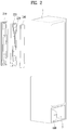
- FIG. 5 is a view illustrating the guide according to the embodiment.
- the guide 230 may include a body 231 which defines the outer appearance of the entire guide 230, and a Phase Change Material (PCM) 233 inside the body 231.
- PCM Phase Change Material
- the through-hole 234 is formed in the center of the guide 230 to allow the discharge port 214 of the duct cover 210 to be inserted thereinto.
- the through-hole 234 is a hole formed in the front surface and the rear surface of the guide 230, the body 231 may be formed so as to be sealed in order to prevent the phase change material 233 received therein from leaking to the outside.
- the guide 230 may have a tapered portion 232, the cross sectional width of which gradually increases from the bottom to the top.
- the tapered portion 232 is a structure that is provided to sequentially cause variation in cross sectional area in order to reduce momentum loss due to the resistance by the guide 230 when the cold air, introduced from the lower side of the duct unit 200, moves to the top of the duct unit 200.
- the lowermost end of the guide 230 may be located lower than the lowermost one of the discharge holes. This serves to increase the probability of heat exchange between the guide 230 and the air supplied through the duct unit 200.
- the body 231 may have greater thermal conductivity than that of the phase change material 233.
- the phase change material 233 is a material that changes between a liquid phase and a solid phase on the basis of a particular temperature, and needs to be charged in the body 231.
- the body 231 needs to successfully transfer variation in external temperature to the phase change material 233.
- the body 231 may have greater thermal conductivity than that of the phase change material 233, which ensures easy heat exchange between the outside and the phase change material 233.
- the body 231 may be formed of HDPE(5200B).
- HDPE(5200B) has high stiffness and shows good resistance at low temperatures as well as chemical resistance.
- HDPE(5200B) is a material provided by HONAM PETROCHEMICAL CORP., and a detailed description thereof will be omitted herein.
- the body 231 needs to be stiff to some extent in order to prevent the phase change material 233 from leaking to the outside due to external shocks or variation in volume depending on temperature variation applied to the phase change material 233.
- the phase change material 233 may have a melting point at a lower temperature than the temperature inside the storage compartment 2, which is set to initiate the driving of the compressor 600.
- the phase change material 233 may discharge a great amount of cold air when changed from a solid phase to a liquid phase. While the compressor 600 is not driven and the temperature inside the storage compartment 2 is increasing, the phase change material 233 may supply accumulated cold air to the storage compartment 2 so that the temperature inside the storage compartment 2 is increased slowly until the temperature of the storage compartment 2 reaches the set temperature for the driving of the compressor 600. In this way, the driving initiation time of the compressor 600 may be delayed, which may reduce power consumption.
- the phase change material 233 may have a melting point near 0°C.
- the melting point refers to the temperature at which the change from a solid phase to a liquid phase occurs.
- the phase change material 233 may accumulate a greater amount of energy at the melting point or the freezing point, at which phase change occurs, than at other temperatures, and may then emit the energy to the outside. That is, when the melting point of the phase change material 233 is near 0 °C, the phase change material 233 may absorb and discharge a greater amount of cold air near 0 °C than that in a different temperature variation range.
- FIG. 5B illustrates an embodiment that is different from that of FIG. 5A . Therefore, the following description focuses on the differences therebetween, and a description of configurations that are the same will be omitted.
- the body 231 into which the phase change material 233 is inserted, forms the upper region of the guide 230.
- the guide member 239 may have the same shape as the lower region of the body 231 of FIG. 5A . However, there is a difference in that no phase change material is inserted in the guide member 239.
- the storage compartment 2 shows a greater increase in temperature in the upper region than that in the lower region as time passes in the state in which the compressor 600 is not driven. This is because cold air has a strong tendency to stay in the lower region, rather than the upper region.
- the phase change material 233 is located at a relatively high height so that the temperature inside the storage compartment 2 is maintained constant without deviation between the upper region and the lower region due to the inclusion of cold air in the phase change material 23 of the guide 230.
- phase change material 233 may accumulate cold air, and therefore the cold air may be supplied to the storage compartment 2 by the phase change material 233 when the temperature of the upper region of the storage compartment 2 increases.
- the frequency of the case where it is necessary to reduce the temperature of the storage compartment 2 by driving the compressor 600 may be reduced, or the driving initiation time of the compressor 600 may be delayed. That is, the total power consumption of the refrigerator may be reduced by the cold air accumulated in the phase change material 233.
- FIG. 6 is a control block diagram according to another embodiment not forming part of the present invention but representing background art that is useful for understanding the invention.
- the temperature sensor 400 may be provided to measure the temperature inside the storage compartment 2. At this time, the temperature measured by the temperature sensor 400 may be transmitted to a controller 300.
- the controller 300 may drive a fan 500, which is capable of creating airflow within the duct unit 200, or may drive the compressor 600 in order to generate cold air.
- the controller 300 may drive both the fan 500 and the compressor 600, or may drive only the compressor 600.
- the controller 300 may drive only the fan 500, without driving the compressor 600.
- the cold air accumulated in the phase change material 233 of the guide 230 may be supplied to the storage compartment 2 through the discharge holes 212.
- the first set temperature may be higher than the second set temperature. That is, when the temperature inside the storage compartment 2 reaches the second set temperature, which is a relatively low temperature, the controller 300 may drive only the fan 500 so as to cool the storage compartment 2 using the cold air that has accumulated in the phase change material 233.
- the guide 230 undergoes heat exchange with the air discharged from the duct unit 200 to the storage compartment 2, the temperature inside the storage compartment 2 is lowered by the guide 230 while the refrigeration cycle device is not operating.
- phase change material 233 maintains a relatively low temperature and undergoes heat exchange with the surrounding air, thereby causing natural convection with air received in the storage compartment 2.
- cooling of the storage compartment 2 may be implemented by the phase change material 233.
- the controller 300 may drive only the compressor 600, or may drive both the compressor 600 and the fan 500, so as to cool the storage compartment 2.
- the temperature of the cold air supplied to the storage compartment 2 may be increased by the guide 230 while the refrigeration cycle device is operated.
- the temperature of the cold air may be increased as the phase change material 233 is cooled because the cold air generated while the compressor 600 is driven has a lower temperature than the temperature of the phase change material 233.
- phase change material 233 may accumulate cold air.
- the cold air supplied while the compressor 600 is driven generally has a lower temperature than the desired set temperature of the storage compartment 2.
- condensation may occur at the exterior of the duct unit 200, and more particularly, at the front surface of the duct cover 210 because of the considerable temperature difference between the interior of the duct unit 200 and the exterior of the duct unit 200.
- the temperature of the cold air passing through the duct unit 200 may be increased via heat exchange with the phase change material 233, which may prevent condensation at the duct unit 200.
- the compressor 600 may supply cold air having a lower temperature than the freezing point of the phase change material 233.
- the temperature that is set to cause the compressor 600, which has stopped, to again be driven may be lower than the temperature that is set to stop the driving of the compressor 600.
- the compressor 600 may be set to be driven when the temperature of the storage compartment 2 reaches 1°C. At this time, the cold air supplied to the storage compartment 2 by the compressor 600 may be set to -1°C. Meanwhile, the compressor 600 may be set to stop driving when the temperature of the storage compartment 2 reaches -0.5°C.
- the aforementioned temperatures are given by way of example, and it should be noted that the actual temperatures may be changed in various ways in the present invention.
- the freezing point (or the melting point) of the phase change material 233 may be -0.75 °C, which is higher than the temperature of the cold air supplied by the compressor 600. This is because the phase change material 233 may accumulate a great amount of cold air at temperatures close to the freezing point.
- the phase change material 233 may accumulate cold air by being changed to a solid phase. While the compressor 600 is not driven, the phase change material 233 may discharge cold air by being changed to a liquid phase, thereby allowing the temperature inside the storage compartment 2 to be maintained for a prescribed length of time.
Applications Claiming Priority (1)
| Application Number | Priority Date | Filing Date | Title |
|---|---|---|---|
| KR1020140160576A KR101706961B1 (ko) | 2014-11-18 | 2014-11-18 | 냉장고 |
Publications (2)
| Publication Number | Publication Date |
|---|---|
| EP3023717A1 EP3023717A1 (en) | 2016-05-25 |
| EP3023717B1 true EP3023717B1 (en) | 2018-12-05 |
Family
ID=54293140
Family Applications (1)
| Application Number | Title | Priority Date | Filing Date |
|---|---|---|---|
| EP15189499.5A Active EP3023717B1 (en) | 2014-11-18 | 2015-10-13 | Refrigerator |
Country Status (3)
| Country | Link |
|---|---|
| US (1) | US20160138849A1 (ko) |
| EP (1) | EP3023717B1 (ko) |
| KR (1) | KR101706961B1 (ko) |
Families Citing this family (15)
| Publication number | Priority date | Publication date | Assignee | Title |
|---|---|---|---|---|
| KR102336200B1 (ko) * | 2014-12-24 | 2021-12-08 | 삼성전자주식회사 | 냉장고 |
| KR101861279B1 (ko) * | 2015-09-21 | 2018-05-25 | 엘지전자 주식회사 | 냉장고 및 냉장고의 냉기 유량 모니터링 시스템 |
| US9671052B2 (en) | 2015-10-27 | 2017-06-06 | Whirlpool Corporation | Collet securing device for joining two fluid lines and providing lateral support at the connection of the two fluid lines |
| KR101835336B1 (ko) * | 2016-03-09 | 2018-03-07 | 엘지전자 주식회사 | 냉장고 |
| US10557469B2 (en) | 2016-03-22 | 2020-02-11 | Whirlpool Corporation | Multi-outlet fluid flow system for an appliance incorporating a bi-directional motor |
| US10655266B2 (en) | 2016-11-30 | 2020-05-19 | Whirlpool Corporation | Lint processing fluid pump for a laundry appliance |
| KR20180073301A (ko) * | 2016-12-22 | 2018-07-02 | 엘지전자 주식회사 | 멀티 덕트 어셈블리 및 멀티 덕트 어셈블리를 포함하는 냉장고, 그리고 냉장고의 제어 방법 |
| US10619289B2 (en) | 2017-02-27 | 2020-04-14 | Whirlpool Corporation | Self cleaning diverter valve |
| US10480117B2 (en) | 2017-02-27 | 2019-11-19 | Whirlpool Corporation | Self cleaning sump cover |
| US10662574B2 (en) | 2017-02-27 | 2020-05-26 | Whirlpool Corporation | Self cleaning heater exchanger plate |
| DE102017205089A1 (de) * | 2017-03-27 | 2018-09-27 | BSH Hausgeräte GmbH | Haushaltskältegerät mit einer Innenverkleidung mit mehreren separaten Verkleidungswänden sowie Verfahren zum Herstellen eines Haushaltskältegeräts |
| US10634412B2 (en) | 2017-04-10 | 2020-04-28 | Whirlpool Corporation | Concealed upstream air tower guide vanes |
| US10697700B2 (en) | 2018-01-17 | 2020-06-30 | Whirlpool Corporation | Refrigeration water dispensing system |
| CN110411123B (zh) * | 2019-07-23 | 2021-06-11 | 安徽康佳同创电器有限公司 | 一种冰箱冷藏风道装置及冰箱 |
| KR200491364Y1 (ko) * | 2020-02-20 | 2020-03-26 | (주)에프엠에스코리아 | 보틀형 냉열팩 |
Citations (1)
| Publication number | Priority date | Publication date | Assignee | Title |
|---|---|---|---|---|
| KR20110089575A (ko) * | 2010-02-01 | 2011-08-09 | 엘지전자 주식회사 | 냉장고 |
Family Cites Families (9)
| Publication number | Priority date | Publication date | Assignee | Title |
|---|---|---|---|---|
| KR0121553B1 (ko) * | 1993-10-08 | 1997-11-15 | 배순훈 | 냉장고의 상변화물질을 이용한 냉각방법 |
| FR2778733B1 (fr) * | 1998-05-12 | 2000-08-18 | Austria Haus Technik Aktienges | Etageres-echangeurs pour meuble frigorifique de vente et meuble frigorifique realise au moyen de telles etageres |
| KR100733077B1 (ko) * | 2006-10-04 | 2007-06-28 | 삼성전자주식회사 | 냉장고 |
| US8790540B2 (en) * | 2009-02-11 | 2014-07-29 | Vkr Holding A/S | Phase change material pack |
| CN102918343A (zh) * | 2010-06-15 | 2013-02-06 | 松下电器产业株式会社 | 冷藏库 |
| KR101781213B1 (ko) * | 2010-07-30 | 2017-09-25 | 엘지전자 주식회사 | 냉각 장치 및 이를 구비한 냉장고 |
| KR101813030B1 (ko) * | 2010-12-29 | 2017-12-28 | 엘지전자 주식회사 | 냉장고 |
| JP5409704B2 (ja) * | 2011-05-24 | 2014-02-05 | 三菱電機株式会社 | 冷蔵庫 |
| JP2013245842A (ja) * | 2012-05-23 | 2013-12-09 | Sharp Corp | 保冷庫 |
-
2014
- 2014-11-18 KR KR1020140160576A patent/KR101706961B1/ko active IP Right Grant
-
2015
- 2015-10-13 EP EP15189499.5A patent/EP3023717B1/en active Active
- 2015-11-16 US US14/941,733 patent/US20160138849A1/en not_active Abandoned
Patent Citations (1)
| Publication number | Priority date | Publication date | Assignee | Title |
|---|---|---|---|---|
| KR20110089575A (ko) * | 2010-02-01 | 2011-08-09 | 엘지전자 주식회사 | 냉장고 |
Also Published As
| Publication number | Publication date |
|---|---|
| US20160138849A1 (en) | 2016-05-19 |
| EP3023717A1 (en) | 2016-05-25 |
| KR20160059129A (ko) | 2016-05-26 |
| KR101706961B1 (ko) | 2017-02-15 |
Similar Documents
| Publication | Publication Date | Title |
|---|---|---|
| EP3023717B1 (en) | Refrigerator | |
| KR101715806B1 (ko) | 냉장고의 제빙시스템 및 제빙방법 | |
| EP2530408B1 (en) | Refrigerator | |
| CN107110589B (zh) | 冰箱 | |
| KR102261114B1 (ko) | 냉장고 | |
| KR102310657B1 (ko) | 냉장고 | |
| US11692757B2 (en) | Refrigerator | |
| EP3217126B1 (en) | Refrigerator | |
| KR102417751B1 (ko) | 냉장고 | |
| KR20100059442A (ko) | 냉장고 및 그 제어방법 | |
| KR101715809B1 (ko) | 냉장고의 제빙시스템 및 제빙방법 | |
| KR20180087618A (ko) | 저장 용기 및 이를 포함하는 냉장고 | |
| JP2003090667A (ja) | 冷蔵庫の製氷室構成 | |
| KR102176725B1 (ko) | 냉장고 | |
| JP2007163066A (ja) | 冷蔵庫 | |
| KR101705666B1 (ko) | 냉장고 및 그 제빙방법 | |
| KR101696893B1 (ko) | 냉장고 및 그 제빙방법 | |
| KR20140019595A (ko) | 3도어 타입 냉장고 | |
| AU2014279424B2 (en) | Refrigerator | |
| KR100614315B1 (ko) | 냉장고 | |
| KR102518816B1 (ko) | 냉장고 및 그 제어 방법 | |
| KR102238538B1 (ko) | 냉장고 | |
| JP2016223754A (ja) | 冷蔵庫 | |
| JP6426915B2 (ja) | 冷蔵庫 | |
| KR100233044B1 (ko) | 냉기토출 제어장치를 구비한 냉장고 |
Legal Events
| Date | Code | Title | Description |
|---|---|---|---|
| AK | Designated contracting states |
Kind code of ref document: A1 Designated state(s): AL AT BE BG CH CY CZ DE DK EE ES FI FR GB GR HR HU IE IS IT LI LT LU LV MC MK MT NL NO PL PT RO RS SE SI SK SM TR |
|
| AX | Request for extension of the european patent |
Extension state: BA ME |
|
| PUAI | Public reference made under article 153(3) epc to a published international application that has entered the european phase |
Free format text: ORIGINAL CODE: 0009012 |
|
| 17P | Request for examination filed |
Effective date: 20160601 |
|
| RBV | Designated contracting states (corrected) |
Designated state(s): AL AT BE BG CH CY CZ DE DK EE ES FI FR GB GR HR HU IE IS IT LI LT LU LV MC MK MT NL NO PL PT RO RS SE SI SK SM TR |
|
| STAA | Information on the status of an ep patent application or granted ep patent |
Free format text: STATUS: EXAMINATION IS IN PROGRESS |
|
| 17Q | First examination report despatched |
Effective date: 20180124 |
|
| REG | Reference to a national code |
Ref country code: DE Ref legal event code: R079 Ref document number: 602015020788 Country of ref document: DE Free format text: PREVIOUS MAIN CLASS: F25D0017060000 Ipc: F25D0017080000 |
|
| GRAP | Despatch of communication of intention to grant a patent |
Free format text: ORIGINAL CODE: EPIDOSNIGR1 |
|
| STAA | Information on the status of an ep patent application or granted ep patent |
Free format text: STATUS: GRANT OF PATENT IS INTENDED |
|
| INTG | Intention to grant announced |
Effective date: 20180615 |
|
| RIC1 | Information provided on ipc code assigned before grant |
Ipc: F25D 17/08 20060101AFI20180605BHEP Ipc: F25D 17/06 20060101ALI20180605BHEP Ipc: F25D 11/00 20060101ALI20180605BHEP |
|
| GRAS | Grant fee paid |
Free format text: ORIGINAL CODE: EPIDOSNIGR3 |
|
| GRAA | (expected) grant |
Free format text: ORIGINAL CODE: 0009210 |
|
| GRAA | (expected) grant |
Free format text: ORIGINAL CODE: 0009210 |
|
| STAA | Information on the status of an ep patent application or granted ep patent |
Free format text: STATUS: THE PATENT HAS BEEN GRANTED |
|
| AK | Designated contracting states |
Kind code of ref document: B1 Designated state(s): AL AT BE BG CH CY CZ DE DK EE ES FI FR GB GR HR HU IE IS IT LI LT LU LV MC MK MT NL NO PL PT RO RS SE SI SK SM TR |
|
| REG | Reference to a national code |
Ref country code: GB Ref legal event code: FG4D |
|
| REG | Reference to a national code |
Ref country code: CH Ref legal event code: EP |
|
| REG | Reference to a national code |
Ref country code: AT Ref legal event code: REF Ref document number: 1073568 Country of ref document: AT Kind code of ref document: T Effective date: 20181215 |
|
| REG | Reference to a national code |
Ref country code: IE Ref legal event code: FG4D |
|
| REG | Reference to a national code |
Ref country code: DE Ref legal event code: R096 Ref document number: 602015020788 Country of ref document: DE |
|
| REG | Reference to a national code |
Ref country code: NL Ref legal event code: MP Effective date: 20181205 |
|
| REG | Reference to a national code |
Ref country code: AT Ref legal event code: MK05 Ref document number: 1073568 Country of ref document: AT Kind code of ref document: T Effective date: 20181205 |
|
| REG | Reference to a national code |
Ref country code: LT Ref legal event code: MG4D |
|
| PG25 | Lapsed in a contracting state [announced via postgrant information from national office to epo] |
Ref country code: FI Free format text: LAPSE BECAUSE OF FAILURE TO SUBMIT A TRANSLATION OF THE DESCRIPTION OR TO PAY THE FEE WITHIN THE PRESCRIBED TIME-LIMIT Effective date: 20181205 Ref country code: LV Free format text: LAPSE BECAUSE OF FAILURE TO SUBMIT A TRANSLATION OF THE DESCRIPTION OR TO PAY THE FEE WITHIN THE PRESCRIBED TIME-LIMIT Effective date: 20181205 Ref country code: AT Free format text: LAPSE BECAUSE OF FAILURE TO SUBMIT A TRANSLATION OF THE DESCRIPTION OR TO PAY THE FEE WITHIN THE PRESCRIBED TIME-LIMIT Effective date: 20181205 Ref country code: HR Free format text: LAPSE BECAUSE OF FAILURE TO SUBMIT A TRANSLATION OF THE DESCRIPTION OR TO PAY THE FEE WITHIN THE PRESCRIBED TIME-LIMIT Effective date: 20181205 Ref country code: BG Free format text: LAPSE BECAUSE OF FAILURE TO SUBMIT A TRANSLATION OF THE DESCRIPTION OR TO PAY THE FEE WITHIN THE PRESCRIBED TIME-LIMIT Effective date: 20190305 Ref country code: ES Free format text: LAPSE BECAUSE OF FAILURE TO SUBMIT A TRANSLATION OF THE DESCRIPTION OR TO PAY THE FEE WITHIN THE PRESCRIBED TIME-LIMIT Effective date: 20181205 Ref country code: LT Free format text: LAPSE BECAUSE OF FAILURE TO SUBMIT A TRANSLATION OF THE DESCRIPTION OR TO PAY THE FEE WITHIN THE PRESCRIBED TIME-LIMIT Effective date: 20181205 Ref country code: NO Free format text: LAPSE BECAUSE OF FAILURE TO SUBMIT A TRANSLATION OF THE DESCRIPTION OR TO PAY THE FEE WITHIN THE PRESCRIBED TIME-LIMIT Effective date: 20190305 |
|
| PG25 | Lapsed in a contracting state [announced via postgrant information from national office to epo] |
Ref country code: AL Free format text: LAPSE BECAUSE OF FAILURE TO SUBMIT A TRANSLATION OF THE DESCRIPTION OR TO PAY THE FEE WITHIN THE PRESCRIBED TIME-LIMIT Effective date: 20181205 Ref country code: GR Free format text: LAPSE BECAUSE OF FAILURE TO SUBMIT A TRANSLATION OF THE DESCRIPTION OR TO PAY THE FEE WITHIN THE PRESCRIBED TIME-LIMIT Effective date: 20190306 Ref country code: RS Free format text: LAPSE BECAUSE OF FAILURE TO SUBMIT A TRANSLATION OF THE DESCRIPTION OR TO PAY THE FEE WITHIN THE PRESCRIBED TIME-LIMIT Effective date: 20181205 Ref country code: SE Free format text: LAPSE BECAUSE OF FAILURE TO SUBMIT A TRANSLATION OF THE DESCRIPTION OR TO PAY THE FEE WITHIN THE PRESCRIBED TIME-LIMIT Effective date: 20181205 |
|
| PG25 | Lapsed in a contracting state [announced via postgrant information from national office to epo] |
Ref country code: NL Free format text: LAPSE BECAUSE OF FAILURE TO SUBMIT A TRANSLATION OF THE DESCRIPTION OR TO PAY THE FEE WITHIN THE PRESCRIBED TIME-LIMIT Effective date: 20181205 |
|
| PG25 | Lapsed in a contracting state [announced via postgrant information from national office to epo] |
Ref country code: CZ Free format text: LAPSE BECAUSE OF FAILURE TO SUBMIT A TRANSLATION OF THE DESCRIPTION OR TO PAY THE FEE WITHIN THE PRESCRIBED TIME-LIMIT Effective date: 20181205 Ref country code: IT Free format text: LAPSE BECAUSE OF FAILURE TO SUBMIT A TRANSLATION OF THE DESCRIPTION OR TO PAY THE FEE WITHIN THE PRESCRIBED TIME-LIMIT Effective date: 20181205 Ref country code: PT Free format text: LAPSE BECAUSE OF FAILURE TO SUBMIT A TRANSLATION OF THE DESCRIPTION OR TO PAY THE FEE WITHIN THE PRESCRIBED TIME-LIMIT Effective date: 20190405 Ref country code: PL Free format text: LAPSE BECAUSE OF FAILURE TO SUBMIT A TRANSLATION OF THE DESCRIPTION OR TO PAY THE FEE WITHIN THE PRESCRIBED TIME-LIMIT Effective date: 20181205 |
|
| PG25 | Lapsed in a contracting state [announced via postgrant information from national office to epo] |
Ref country code: SM Free format text: LAPSE BECAUSE OF FAILURE TO SUBMIT A TRANSLATION OF THE DESCRIPTION OR TO PAY THE FEE WITHIN THE PRESCRIBED TIME-LIMIT Effective date: 20181205 Ref country code: EE Free format text: LAPSE BECAUSE OF FAILURE TO SUBMIT A TRANSLATION OF THE DESCRIPTION OR TO PAY THE FEE WITHIN THE PRESCRIBED TIME-LIMIT Effective date: 20181205 Ref country code: SK Free format text: LAPSE BECAUSE OF FAILURE TO SUBMIT A TRANSLATION OF THE DESCRIPTION OR TO PAY THE FEE WITHIN THE PRESCRIBED TIME-LIMIT Effective date: 20181205 Ref country code: IS Free format text: LAPSE BECAUSE OF FAILURE TO SUBMIT A TRANSLATION OF THE DESCRIPTION OR TO PAY THE FEE WITHIN THE PRESCRIBED TIME-LIMIT Effective date: 20190405 Ref country code: RO Free format text: LAPSE BECAUSE OF FAILURE TO SUBMIT A TRANSLATION OF THE DESCRIPTION OR TO PAY THE FEE WITHIN THE PRESCRIBED TIME-LIMIT Effective date: 20181205 |
|
| REG | Reference to a national code |
Ref country code: DE Ref legal event code: R097 Ref document number: 602015020788 Country of ref document: DE |
|
| PLBE | No opposition filed within time limit |
Free format text: ORIGINAL CODE: 0009261 |
|
| STAA | Information on the status of an ep patent application or granted ep patent |
Free format text: STATUS: NO OPPOSITION FILED WITHIN TIME LIMIT |
|
| PG25 | Lapsed in a contracting state [announced via postgrant information from national office to epo] |
Ref country code: SI Free format text: LAPSE BECAUSE OF FAILURE TO SUBMIT A TRANSLATION OF THE DESCRIPTION OR TO PAY THE FEE WITHIN THE PRESCRIBED TIME-LIMIT Effective date: 20181205 Ref country code: DK Free format text: LAPSE BECAUSE OF FAILURE TO SUBMIT A TRANSLATION OF THE DESCRIPTION OR TO PAY THE FEE WITHIN THE PRESCRIBED TIME-LIMIT Effective date: 20181205 |
|
| 26N | No opposition filed |
Effective date: 20190906 |
|
| PG25 | Lapsed in a contracting state [announced via postgrant information from national office to epo] |
Ref country code: TR Free format text: LAPSE BECAUSE OF FAILURE TO SUBMIT A TRANSLATION OF THE DESCRIPTION OR TO PAY THE FEE WITHIN THE PRESCRIBED TIME-LIMIT Effective date: 20181205 |
|
| PG25 | Lapsed in a contracting state [announced via postgrant information from national office to epo] |
Ref country code: MC Free format text: LAPSE BECAUSE OF FAILURE TO SUBMIT A TRANSLATION OF THE DESCRIPTION OR TO PAY THE FEE WITHIN THE PRESCRIBED TIME-LIMIT Effective date: 20181205 |
|
| REG | Reference to a national code |
Ref country code: CH Ref legal event code: PL |
|
| PG25 | Lapsed in a contracting state [announced via postgrant information from national office to epo] |
Ref country code: LU Free format text: LAPSE BECAUSE OF NON-PAYMENT OF DUE FEES Effective date: 20191013 Ref country code: LI Free format text: LAPSE BECAUSE OF NON-PAYMENT OF DUE FEES Effective date: 20191031 Ref country code: CH Free format text: LAPSE BECAUSE OF NON-PAYMENT OF DUE FEES Effective date: 20191031 |
|
| REG | Reference to a national code |
Ref country code: BE Ref legal event code: MM Effective date: 20191031 |
|
| PG25 | Lapsed in a contracting state [announced via postgrant information from national office to epo] |
Ref country code: BE Free format text: LAPSE BECAUSE OF NON-PAYMENT OF DUE FEES Effective date: 20191031 |
|
| GBPC | Gb: european patent ceased through non-payment of renewal fee |
Effective date: 20191013 |
|
| PG25 | Lapsed in a contracting state [announced via postgrant information from national office to epo] |
Ref country code: IE Free format text: LAPSE BECAUSE OF NON-PAYMENT OF DUE FEES Effective date: 20191013 Ref country code: GB Free format text: LAPSE BECAUSE OF NON-PAYMENT OF DUE FEES Effective date: 20191013 Ref country code: FR Free format text: LAPSE BECAUSE OF NON-PAYMENT OF DUE FEES Effective date: 20191031 |
|
| PG25 | Lapsed in a contracting state [announced via postgrant information from national office to epo] |
Ref country code: CY Free format text: LAPSE BECAUSE OF FAILURE TO SUBMIT A TRANSLATION OF THE DESCRIPTION OR TO PAY THE FEE WITHIN THE PRESCRIBED TIME-LIMIT Effective date: 20181205 |
|
| PG25 | Lapsed in a contracting state [announced via postgrant information from national office to epo] |
Ref country code: HU Free format text: LAPSE BECAUSE OF FAILURE TO SUBMIT A TRANSLATION OF THE DESCRIPTION OR TO PAY THE FEE WITHIN THE PRESCRIBED TIME-LIMIT; INVALID AB INITIO Effective date: 20151013 Ref country code: MT Free format text: LAPSE BECAUSE OF FAILURE TO SUBMIT A TRANSLATION OF THE DESCRIPTION OR TO PAY THE FEE WITHIN THE PRESCRIBED TIME-LIMIT Effective date: 20181205 |
|
| PG25 | Lapsed in a contracting state [announced via postgrant information from national office to epo] |
Ref country code: MK Free format text: LAPSE BECAUSE OF FAILURE TO SUBMIT A TRANSLATION OF THE DESCRIPTION OR TO PAY THE FEE WITHIN THE PRESCRIBED TIME-LIMIT Effective date: 20181205 |
|
| REG | Reference to a national code |
Ref country code: DE Ref legal event code: R082 Ref document number: 602015020788 Country of ref document: DE Representative=s name: TER MEER STEINMEISTER & PARTNER PATENTANWAELTE, DE |
|
| PGFP | Annual fee paid to national office [announced via postgrant information from national office to epo] |
Ref country code: DE Payment date: 20230905 Year of fee payment: 9 |