EP3023663B1 - Thermische trennanordnung mit flugsteuerung-permanentmagnetgenerator für integrierten antriebsgenerator - Google Patents
Thermische trennanordnung mit flugsteuerung-permanentmagnetgenerator für integrierten antriebsgenerator Download PDFInfo
- Publication number
- EP3023663B1 EP3023663B1 EP15195588.7A EP15195588A EP3023663B1 EP 3023663 B1 EP3023663 B1 EP 3023663B1 EP 15195588 A EP15195588 A EP 15195588A EP 3023663 B1 EP3023663 B1 EP 3023663B1
- Authority
- EP
- European Patent Office
- Prior art keywords
- input shaft
- output shaft
- coupled
- disconnect
- permanent magnet
- Prior art date
- Legal status (The legal status is an assumption and is not a legal conclusion. Google has not performed a legal analysis and makes no representation as to the accuracy of the status listed.)
- Active
Links
Images


Classifications
-
- F—MECHANICAL ENGINEERING; LIGHTING; HEATING; WEAPONS; BLASTING
- F16—ENGINEERING ELEMENTS AND UNITS; GENERAL MEASURES FOR PRODUCING AND MAINTAINING EFFECTIVE FUNCTIONING OF MACHINES OR INSTALLATIONS; THERMAL INSULATION IN GENERAL
- F16D—COUPLINGS FOR TRANSMITTING ROTATION; CLUTCHES; BRAKES
- F16D9/00—Couplings with safety member for disconnecting, e.g. breaking or melting member
- F16D9/02—Couplings with safety member for disconnecting, e.g. breaking or melting member by thermal means, e.g. melting member
-
- F—MECHANICAL ENGINEERING; LIGHTING; HEATING; WEAPONS; BLASTING
- F16—ENGINEERING ELEMENTS AND UNITS; GENERAL MEASURES FOR PRODUCING AND MAINTAINING EFFECTIVE FUNCTIONING OF MACHINES OR INSTALLATIONS; THERMAL INSULATION IN GENERAL
- F16D—COUPLINGS FOR TRANSMITTING ROTATION; CLUTCHES; BRAKES
- F16D23/00—Details of mechanically-actuated clutches not specific for one distinct type
- F16D23/12—Mechanical clutch-actuating mechanisms arranged outside the clutch as such
- F16D2023/123—Clutch actuation by cams, ramps or ball-screw mechanisms
Definitions
- the present invention relates generally to integrated drive generators, and in particular to a thermal disconnect for an integrated drive generator.
- IDGs Integrated drive generators
- IDGs which are driven, for example, by an input shaft from the turbine engine, typically include a generator, a differential gear assembly and a hydraulic speed trimming device.
- the speed trimming device is utilized to control the speed of the generator in relation to the mechanical input to the IDG such that the generator rotates at a constant speed. Failures may occur during operation of the IDG that cause excessive temperatures within the IDG. It is desirable to decouple the IDG from the gas turbine engine upon occurrence of a failure in order to prevent further failures and degradation of the system.
- thermal disconnect assembly as set forth in claim 1.
- a thermal disconnect assembly with a flight control permanent magnet generator (PMG) for an integrated drive generator (IDG) is disclosed herein that provides disconnection of the IDG from an input shaft upon occurrence of a failure condition.
- the thermal disconnect assembly includes an output shaft, eutectic solder, and disconnect clutch.
- the input shaft is driven by an external mechanical source.
- the output shaft is coupled to the input shaft through a disconnect clutch when in a coupled state.
- the output shaft is driven by the input shaft and rotates with the input shaft while in the coupled state.
- the output shaft drives the flight control PMG through an output gear assembly that also drives the IDG.
- the eutectic solder is configured to hold the output shaft in the coupled state and melt upon reaching a threshold temperature.
- the disconnect clutch is configured to urge the output shaft toward a decoupled state upon melting of the eutectic solder.
- the output shaft does not rotate with the input shaft in the decoupled state. This way, the IDG is disconnected from the input mechanical source upon occurrence of a failure within the IDG, preventing further failures and degradation of the system.
- FIG. 1 is a block diagram illustrating integrated drive generator (IDG) 10 that includes disconnect assembly 12.
- IDG 10 includes disconnect assembly 12, input shaft 14, gear assembly 16, speed limiter 18, and generator 20.
- IDG 10 may be utilized, for example, in an aircraft to provide constant frequency output power.
- IDG 10 is configured to receive rotational energy on input shaft 14 at, for example, varying rotational speeds from a prime mover (not illustrated) such as a gas turbine engine accessory gear box.
- Generator 20 produces an electrical output having, for example, a constant output frequency, such as 3-phase 115 Volt (V) alternating current (AC) at 400 Hertz (Hz).
- a constant output frequency such as 3-phase 115 Volt (V) alternating current (AC) at 400 Hertz (Hz).
- generator 20 rotates at a constant speed.
- Speed limiter 18, which may be a hydraulic speed trimming device, for example, may be located proximate to generator 20.
- Speed limiter 18 may hydro-mechanically regulate the speed of rotational energy provided to generator 20.
- speed limiter 18 may be configured to provide rotational energy that adds or subtracts speed through gear assembly 16 to input shaft 14 so that the speed of generator 20 is constant.
- Gear assembly 16 may be, for example, an epicyclic differential gear system.
- Gear assembly 16 is operably coupled to speed trimming device 18 and forms a gear relationship with generator 20, speed trimming device 18, and input shaft 14 through disconnect assembly 12.
- generator 20, speed trimming device 18 and gear assembly 16 may be disposed about, for example, separate centerlines dependent upon design considerations.
- Input shaft 14 and disconnect assembly 12 may be oriented about the same centerline.
- Disconnect assembly 12 is utilized to disconnect IDG 10 from the external system through input shaft 14 in order to prevent further failures or damage to IDG 10 and the external system.
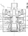
- FIGS. 2A and 2B are cross-sectional views illustrating disconnect assembly 12 for an integrated drive generator (IDG) in a coupled and decoupled state, respectively.
- Disconnect assembly 12 includes input shaft 14, output shaft 30, output gear 32, flight control permanent magnet generator (PMG) 34, eutectic solder 36, disconnect clutch 38, spring 40, disconnect bearing 42, and molten solder collector 44.
- Output shaft 30 and output gear 32 are coupled through spline 46.
- Output gear 32 and flight control PMG 34 are coupled through thread 48.
- Disconnect bearing 42 includes inner race 50, outer race 52, and ball bearings 54.
- Input shaft 14 and output shaft 30 are oriented about centerline C L .
- FIG. 2A illustrates disconnect assembly 12 in a coupled state.
- eutectic solder 36 which is annular about centerline C L , biases output shaft 30 such that output shaft 30 is held coupled to input shaft 14 through disconnect clutch 38.
- Disconnect clutch 38 which may also be referred to as a disconnect jaws, may be any known disconnect clutch such as, for example, a face clutch. Face clutches are configured, for example, with angles (not shown) such that output shaft 30 is urged away from input shaft 14 during the transfer of rotational energy.
- Eutectic solder 36 prevents this separation from occurring during normal system operation in the coupled state.
- output shaft 30 is coupled to input shaft 14 through disconnect clutch 38, output shaft 30 is driven by, and rotates with, input shaft 14.
- Output shaft 30 is coupled to output gear 32 through spline 46 and thus, output gear 32 rotates with output shaft 30.
- Output gear 32 is coupled to drive the rest of gear assembly 16 ( FIG. 1 ).
- Output gear 32 is also coupled to drive flight control PMG 34 through thread 48.
- Flight control PMG 34 is operably driven by output shaft 30 and is utilized to provide, for example, dedicated variable frequency output power. This output power may be utilized, for example, to provide power for any aircraft systems that desire dedicated power such as flight control avionics.
- Flight control PMG 34 is configured to support input shaft 14 through disconnect bearing 42. While in the coupled state, inner race 50 and outer race 52 rotate together. This eliminates contact fatigue degradation of disconnect bearing 42 while input shaft 14 and output shaft 30 are in the coupled state which increases the life of disconnect bearing 42.
- Eutectic solder 36 is configured to melt upon reaching a threshold temperature.
- Eutectic solder 36 may be made of any suitable material such as, for example, tin alloy, which may have a melting point of three hundred ninety-four degrees Fahrenheit (F) (201°C). At temperatures below the threshold temperature, eutectic solder 36 remains solid and holds output shaft 30 in the coupled state.
- Eutectic solder 36 is annular about centerline C L and positioned between output shaft 30 and molten solder collector 44. Upon the temperature reaching the threshold temperature, eutectic solder 36 melts.
- disconnect clutch 38 and spring 40 urge output shaft 30 in the axial direction away from input shaft 14, disconnecting output shaft 30 from input shaft 14.
- Spline 46 permits output shaft 30 to move axially toward solder collector 44 while remaining coupled to output gear 32.
- FIG. 2B illustrates disconnect assembly 12 in a decoupled state.
- Output shaft 30 is no longer coupled to input shaft 14 through disconnect clutch 38. Therefore, input shaft 14 rotates while output shaft 30 remains stationary relative to input shaft 14. Because of this, IDG 10 receives no mechanical input power and produces no electrical output power, which prevents further damage and degradation to IDG 10.
- the molten eutectic solder is collected by molten solder collector 44. Upon initial melting of eutectic solder 36, the rotational energy of output shaft 30 forces eutectic solder 36 into molten solder collector 44 as it melts.
- Molten solder collector 44 is configured, for example, such that eutectic solder 36 is held in place when solid, and is collected into molten solder collector 44 when melted.
- Annular spring 40 is extended in the decoupled state and holds output shaft 30 in the decoupled state.
- Spring 40 is implemented, for example, between a ridge on an outer surface of output shaft 30 and a ridge in the inner surface of output gear 32. When extended, spring 40 inhibits motion of output shaft 30 in the axial direction toward input shaft 14, ensuring that output shaft 30 remains decoupled from input shaft 40.
- Flight control PMG 34 because it is coupled to output gear 32, also ceases to rotate in the decoupled state. In the coupled state, flight control PMG 34 continues to provide support for input shaft 14. While flight control PMG 34 is stationary relative to input shaft 14, inner race 50 rotates with input shaft 14, while ball bearings 54 allow outer race 52 to remain stationary relative to inner race 50. In this way, IDG 10 may be disconnected from the prime mover (not shown) and remain disconnected for any desirable time period.
- a thermal disconnect assembly for an integrated drive generator includes an input shaft, an output shaft, a eutectic solder, and a disconnect clutch.
- the input shaft is driven by an external mechanical source.
- the output shaft is coupled to the input shaft through a disconnect clutch in a coupled state, is driven by the input shaft and rotates with the input shaft in the coupled state.
- the eutectic solder is configured to hold the output shaft in the coupled state and melt upon reaching a threshold temperature.
- the disconnect clutch is configured to urge the output shaft toward a decoupled state upon melting of the eutectic solder such that the output shaft does not rotate with the input shaft in the decoupled state.
- thermal disconnect assembly of the preceding paragraph can optionally include, additionally and/or alternatively, any one or more of the following features, configurations and/or additional components:
- a further embodiment of the foregoing thermal disconnect assembly wherein the input shaft and the output shaft are oriented about a common centerline, and wherein the output shaft is configured to move axially along the centerline upon melting of the eutectic solder.
- thermal disconnect assemblies further including a flight control permanent magnet generator operably coupled to rotate with the output shaft, wherein the flight control generator is located annularly about the input shaft.
- disconnect bearing includes an inner race coupled to the input shaft and configured to rotate with the input shaft, an outer race coupled to the flight control permanent magnet generator and configured to rotate with the flight control permanent magnet generator, wherein the outer race is coupled to the inner race through ball bearings, and wherein the outer race and the inner race rotate together in the coupled state, and wherein the inner race rotates relative to the outer race in the decoupled state.
- thermal disconnect assemblies further comprising a spring that biases the output shaft to the decoupled state upon melting of the eutectic solder.
- thermal disconnect assemblies further comprising a solder collector, wherein the spring biases the output shaft into the solder collector in the decoupled state to collect the eutectic solder.
- a method of disconnecting an input shaft from an output shaft of an integrated drive generator includes holding, using a eutectic solder, the input shaft and the output shaft in a coupled state; driving, by a mechanical power source, the input shaft such that the input shaft rotates about a first axis; driving, by the input shaft, the output shaft in the coupled state; melting the eutectic solder upon a temperature of the eutectic solder reaching a threshold value; and moving, using a disconnect clutch, the output shaft axially away from the input shaft to a decoupled state upon melting of the eutectic solder.
- the method of the preceding paragraph can optionally include, additionally and/or alternatively, any one or more of the following features, configurations and/or additional components: A further embodiment of the foregoing method, wherein driving, by the input shaft, the output shaft further includes driving, by the output shaft, a permanent magnet generator oriented annularly about the input shaft, wherein the permanent magnet generator is coupled to the input shaft through a disconnect bearing.
- driving, by the output shaft, the permanent magnet generator comprises rotating an outer race of the disconnect bearing together with an inner race of the disconnect bearing.
- a further embodiment of any of the foregoing methods further including rotating the inner race of the disconnect bearing relative to the outer race of the disconnect bearing in the decoupled state.
- a further embodiment of any of the foregoing methods further including biasing, using a spring, the output shaft axially away from the input shaft to hold the output shaft in the decoupled state.
- a further embodiment of any of the foregoing methods further including collecting, using a solder collector, the melted eutectic solder, wherein the output shaft moves axially toward the solder collector to force the melted eutectic solder into the solder collector.
Landscapes
- Engineering & Computer Science (AREA)
- General Engineering & Computer Science (AREA)
- Mechanical Engineering (AREA)
- Connection Of Motors, Electrical Generators, Mechanical Devices, And The Like (AREA)
Claims (6)
- Thermische Trennanordnung (12) für einen integrierten Antriebsgenerator (20), die eine Eingangswelle (14), die durch eine externe mechanische Quelle angetrieben wird, eine Ausgangswelle (30), die durch eine Trennkupplung (38) in einem gekoppelten Zustand an die Eingangswelle (14) gekoppelt ist, wobei die Ausgangswelle (30) in dem gekoppelten Zustand durch die Eingangswelle (14) angetrieben wird und sich mit der Eingangswelle (14) dreht, ein eutektisches Lötmittel (36), das konfiguriert ist, um die Ausgangswelle (30) in dem gekoppelten Zustand zu halten, wobei das eutektische Lötmittel (36) konfiguriert ist, um bei Erreichen einer Schwellentemperatur zu schmelzen, und einen Flugsteuerung-Permanentmagnetgenerator (34) beinhaltet; wobei die thermische Trennanordnung (12) dadurch gekennzeichnet ist, dass:der Flugsteuerung-Permanentmagnetgenerator (34) wirkgekoppelt ist, um sich mit der Ausgangswelle (30) zu drehen und wobei sich der Flugsteuerung-Permanentmagnetgenerator (34) ringförmig um die Eingangswelle (14) herum befindet und durch ein Trennlager (42) an die Eingangswelle (14) gekoppelt ist, und wobei das Trennlager (42) Folgendes umfasst:einen Innenring (50), der an die Eingangswelle (14) gekoppelt und konfiguriert ist, um sich mit der Eingangswelle (14) zu drehen;einen Außenring (52), der an den Flugsteuerung-Permanentmagnetgenerator (34) gekoppelt und konfiguriert ist, um sich mit dem Flugsteuerung-Permanentmagnetgenerator (34) zu drehen, wobei der Außenring (52) durch Kugellager (54) an den Innenring (50) gekoppelt ist; undwobei sich der Außenring (52) und der Innenring (50) in dem gekoppelten Zustand zusammen drehen und wobei sich in dem entkoppelten Zustand der Innenring (50) relativ zu dem Außenring (52) dreht; undwobei die Trennkupplung (38) konfiguriert ist, um die Ausgangswelle (30) bei Schmelzen des eutektischen Lötmittels (36) in Richtung eines entkoppelten Zustands zu drängen, und wobei sich in dem entkoppelten Zustand die Ausgangswelle (30) nicht mit der Eingangswelle (14) dreht.
- Thermische Trennanordnung nach Anspruch 1, wobei die Eingangswelle (14) und die Ausgangswelle (30) um eine gemeinsame Mittellinie (CL) herum ausgerichtet sind, und wobei die Ausgangswelle (30) konfiguriert ist, um sich bei Schmelzen des eutektischen Lötmittels (36) axial entlang der Mittellinie (CL) zu bewegen.
- Thermische Trennanordnung nach einem der Ansprüche 1 oder 2, wobei der Flugsteuerung-Permanentmagnetgenerator (34) wirkgekoppelt ist, um sich durch ein Ausgangsgetriebe (32) mit der Ausgangswelle (30) zu drehen.
- Thermische Trennanordnung nach Anspruch 3, ferner umfassend einen Lötmittelsammler (44), wobei die Feder (40) die Ausgangswelle (30) in dem entkoppelten Zustand in den Lötmittelsammler (44) vorspannt, um das eutektische Lötmittel (36) zu sammeln.
- Verfahren zum Trennen einer Eingangswelle (14) von einer Ausgangswelle (30) eines integrierten Antriebsgenerators (12), wobei das Verfahren Folgendes umfasst:Halten, unter Verwendung eines eutektischen Lötmittels (36), der Eingangswelle (14) und der Ausgangswelle (30) in einem gekoppelten Zustand;Antreiben, durch die Ausgangswelle (30), eines Permanentmagnetgenerators (34), der ringförmig um die Eingangswelle (14) herum ausgerichtet ist, wobei der Permanentmagnetgenerator (34) durch ein Trennlager (42), das Folgendes umfasst, an die Eingangswelle (14) gekoppelt ist:einen Innenring (50), der an die Eingangswelle (14) gekoppelt und konfiguriert ist, um sich mit der Eingangswelle (14) zu drehen; undeinen Außenring (52), der an den Permanentmagnetgenerator (34) gekoppelt und konfiguriert ist, um sich mit dem Permanentmagnetgenerator (34) zu drehen, wobei der Außenring (52) durch Kugellager (54) an den Innenring (50) gekoppelt ist;Drehen eines Außenrings (52) des Trennlagers (42) zusammen mit einem Innenring (50) des Trennlagers (42);Antreiben der Eingangswelle (14) durch eine mechanische Leistungsquelle, wobei sich die Eingangswelle (14) um eine erste Achse (CL) dreht;Antreiben der Ausgangswelle (30) durch die Eingangswelle (14) in dem gekoppelten Zustand;Schmelzen des eutektischen Lötmittels (36), wenn eine Temperatur des eutektischen Lötmittels (36) einen Schwellenwert erreicht;Bewegen der Ausgangswelle (30) axial weg von der Eingangswelle (14) in einen entkoppelten Zustand unter Verwendung einer Trennkupplung (38) bei Schmelzen des eutektischen Lötmittels (36); undDrehen des Innenrings (50) des Trennlagers (42) relativ zu dem Außenring (52) des Trennlagers (42) in dem entkoppelten Zustand.
- Verfahren nach Anspruch 5, ferner umfassend:
Vorspannen der Ausgangswelle (30) axial weg von der Eingangswelle (14) unter Verwendung einer Feder (40), um die Ausgangswelle (30) in dem entkoppelten Zustand zu halten.
Applications Claiming Priority (1)
| Application Number | Priority Date | Filing Date | Title |
|---|---|---|---|
| US14/548,665 US9574618B2 (en) | 2014-11-20 | 2014-11-20 | Thermal disconnect assembly with flight control permanent magnet generator for integrated drive generator |
Publications (2)
| Publication Number | Publication Date |
|---|---|
| EP3023663A1 EP3023663A1 (de) | 2016-05-25 |
| EP3023663B1 true EP3023663B1 (de) | 2019-03-27 |
Family
ID=54703798
Family Applications (1)
| Application Number | Title | Priority Date | Filing Date |
|---|---|---|---|
| EP15195588.7A Active EP3023663B1 (de) | 2014-11-20 | 2015-11-20 | Thermische trennanordnung mit flugsteuerung-permanentmagnetgenerator für integrierten antriebsgenerator |
Country Status (2)
| Country | Link |
|---|---|
| US (1) | US9574618B2 (de) |
| EP (1) | EP3023663B1 (de) |
Families Citing this family (6)
| Publication number | Priority date | Publication date | Assignee | Title |
|---|---|---|---|---|
| US11143309B2 (en) | 2018-10-09 | 2021-10-12 | Hamilton Sundstrand Corporation | Disconnect bearing and input seal for a variable frequency starter generator |
| EP3885561A4 (de) * | 2018-11-19 | 2022-06-22 | Kawasaki Jukogyo Kabushiki Kaisha | Energieerzeugungsvorrichtung für ein flugzeug |
| JP2020106048A (ja) * | 2018-12-26 | 2020-07-09 | 本田技研工業株式会社 | 車両用駆動装置 |
| KR102660418B1 (ko) * | 2019-03-14 | 2024-04-24 | 에이치엘만도 주식회사 | 잠김 해제 방법, 잠김 해제 장치 및 이를 포함하는 조향 보조 장치 |
| US11668352B2 (en) * | 2019-06-10 | 2023-06-06 | Honda Motor Co., Ltd. | Final drive assembly, powertrain for a vehicle, and method of containing a shaft |
| US11152837B2 (en) | 2019-09-06 | 2021-10-19 | Hamilton Sundstrand Corporation | Generator arrangements and methods of generating electric power with generator arrangements |
Family Cites Families (14)
| Publication number | Priority date | Publication date | Assignee | Title |
|---|---|---|---|---|
| US3889789A (en) * | 1974-04-15 | 1975-06-17 | Mc Donnell Douglas Corp | Thermal fuse mechanical disconnect |
| US4086991A (en) | 1976-10-14 | 1978-05-02 | Sundstrand Corporation | Thermally actuated disconnect coupling |
| GB1600977A (en) | 1977-08-10 | 1981-10-21 | Lucas Industries Ltd | Couplings |
| US4271947A (en) * | 1978-11-13 | 1981-06-09 | General Electric Company | Thermal fuze mechanical disconnect eutectic containment |
| US4934977A (en) * | 1985-11-07 | 1990-06-19 | Sundstrand Corporation | Thermal disconnect coupling |
| US5103949A (en) * | 1990-11-08 | 1992-04-14 | Sundstrand Corporation | Thermal disconnect |
| GB0016178D0 (en) | 2000-06-30 | 2000-08-23 | Lucas Industries Ltd | Thermal disconnect |
| US6364772B1 (en) * | 2000-08-22 | 2002-04-02 | Hamilton Sundstrand Corporation | Disconnect for high-speed rotating shafts |
| GB0101859D0 (en) * | 2001-01-24 | 2001-03-07 | Lucas Industries Ltd | A thermal disconnect device |
| FR2827927B1 (fr) * | 2001-07-27 | 2003-10-17 | Thales Sa | Dispositif d'accouplement a crabot |
| GB0412203D0 (en) * | 2004-06-01 | 2004-07-07 | Goodrich Control Sys Ltd | Disconnect mechanism and devices including such a disconnect mechanism |
| GB0820232D0 (en) * | 2008-11-05 | 2008-12-10 | Goodrich Control Sys Ltd | Releasable drive arrangement |
| US8102089B2 (en) * | 2009-07-02 | 2012-01-24 | Hamilton Sundstrand Corporation | Generator rotor bearing preload method and apparatus |
| US20140008170A1 (en) | 2012-07-06 | 2014-01-09 | Henry R. Vanderzyden | Integrated drive generator disconnect assembly |
-
2014
- 2014-11-20 US US14/548,665 patent/US9574618B2/en active Active
-
2015
- 2015-11-20 EP EP15195588.7A patent/EP3023663B1/de active Active
Non-Patent Citations (1)
| Title |
|---|
| None * |
Also Published As
| Publication number | Publication date |
|---|---|
| EP3023663A1 (de) | 2016-05-25 |
| US9574618B2 (en) | 2017-02-21 |
| US20160146264A1 (en) | 2016-05-26 |
Similar Documents
| Publication | Publication Date | Title |
|---|---|---|
| EP3023663B1 (de) | Thermische trennanordnung mit flugsteuerung-permanentmagnetgenerator für integrierten antriebsgenerator | |
| EP2199573B1 (de) | Generatorkupplung zur Verwendung mit Gasturbinenmotor | |
| US8456051B2 (en) | High reliability generator with dual drive path | |
| US20060137355A1 (en) | Fan driven emergency generator | |
| AU2020414869B2 (en) | Parallel bearing and rotor system | |
| US10626925B2 (en) | Gas turbine engine with a geared turbofan arrangement | |
| EP2770223B1 (de) | Maschine mit Sicherheitslager | |
| US20230323788A1 (en) | Turbomachine having a free turbine comprising electric machines assisting a gas generator and a free turbine | |
| US20140219598A1 (en) | Variable frequency generator input shaft bearing | |
| US20190036418A1 (en) | Permanent-Magnet Synchronous Machine with Automatic Rotor Decoupling in the Winding Short Circuit | |
| EP3065275B1 (de) | Gasturbinenmotor mit magnetischem getriebe | |
| EP3555446B1 (de) | Luftturbinenstarter mit entkoppler | |
| US10316898B2 (en) | Method and disconnector for disconnecting a drive shaft | |
| JP6155713B2 (ja) | 風力発電装置用の一方向クラッチ及び風力発電装置 | |
| JP2017155665A (ja) | タービンのターニング装置 | |
| EP2503171A2 (de) | Lastkopplung für Stromerzeugungssysteme | |
| JP6142587B2 (ja) | クラッチユニット及び風力発電装置 | |
| EP3636968B1 (de) | Verbessertes trennlager und eingangsdichtung für einen startergenerator mit variabler frequenz | |
| CN105074256B (zh) | 发电设备和单向离合器结构 | |
| US9057407B2 (en) | Disconnect assembly | |
| EP3530972B1 (de) | Wellenscherungsquerschnitt | |
| JP2014173547A (ja) | 発電装置 | |
| US12522064B2 (en) | Drive shaft assembly for driven accessory devices | |
| JP6064692B2 (ja) | 風力発電装置 | |
| KR20200025013A (ko) | 전력계통의 서지 등에 의해 발전기에서 발생하는 충격토크 차단을 위한 장치 |
Legal Events
| Date | Code | Title | Description |
|---|---|---|---|
| AK | Designated contracting states |
Kind code of ref document: A1 Designated state(s): AL AT BE BG CH CY CZ DE DK EE ES FI FR GB GR HR HU IE IS IT LI LT LU LV MC MK MT NL NO PL PT RO RS SE SI SK SM TR |
|
| AX | Request for extension of the european patent |
Extension state: BA ME |
|
| PUAI | Public reference made under article 153(3) epc to a published international application that has entered the european phase |
Free format text: ORIGINAL CODE: 0009012 |
|
| STAA | Information on the status of an ep patent application or granted ep patent |
Free format text: STATUS: REQUEST FOR EXAMINATION WAS MADE |
|
| 17P | Request for examination filed |
Effective date: 20161125 |
|
| RBV | Designated contracting states (corrected) |
Designated state(s): AL AT BE BG CH CY CZ DE DK EE ES FI FR GB GR HR HU IE IS IT LI LT LU LV MC MK MT NL NO PL PT RO RS SE SI SK SM TR |
|
| STAA | Information on the status of an ep patent application or granted ep patent |
Free format text: STATUS: EXAMINATION IS IN PROGRESS |
|
| 17Q | First examination report despatched |
Effective date: 20170711 |
|
| GRAP | Despatch of communication of intention to grant a patent |
Free format text: ORIGINAL CODE: EPIDOSNIGR1 |
|
| STAA | Information on the status of an ep patent application or granted ep patent |
Free format text: STATUS: GRANT OF PATENT IS INTENDED |
|
| INTG | Intention to grant announced |
Effective date: 20180925 |
|
| GRAJ | Information related to disapproval of communication of intention to grant by the applicant or resumption of examination proceedings by the epo deleted |
Free format text: ORIGINAL CODE: EPIDOSDIGR1 |
|
| GRAL | Information related to payment of fee for publishing/printing deleted |
Free format text: ORIGINAL CODE: EPIDOSDIGR3 |
|
| GRAS | Grant fee paid |
Free format text: ORIGINAL CODE: EPIDOSNIGR3 |
|
| STAA | Information on the status of an ep patent application or granted ep patent |
Free format text: STATUS: EXAMINATION IS IN PROGRESS |
|
| GRAR | Information related to intention to grant a patent recorded |
Free format text: ORIGINAL CODE: EPIDOSNIGR71 |
|
| STAA | Information on the status of an ep patent application or granted ep patent |
Free format text: STATUS: GRANT OF PATENT IS INTENDED |
|
| GRAA | (expected) grant |
Free format text: ORIGINAL CODE: 0009210 |
|
| STAA | Information on the status of an ep patent application or granted ep patent |
Free format text: STATUS: THE PATENT HAS BEEN GRANTED |
|
| INTC | Intention to grant announced (deleted) | ||
| AK | Designated contracting states |
Kind code of ref document: B1 Designated state(s): AL AT BE BG CH CY CZ DE DK EE ES FI FR GB GR HR HU IE IS IT LI LT LU LV MC MK MT NL NO PL PT RO RS SE SI SK SM TR |
|
| INTG | Intention to grant announced |
Effective date: 20190218 |
|
| REG | Reference to a national code |
Ref country code: GB Ref legal event code: FG4D |
|
| REG | Reference to a national code |
Ref country code: CH Ref legal event code: EP |
|
| REG | Reference to a national code |
Ref country code: AT Ref legal event code: REF Ref document number: 1113461 Country of ref document: AT Kind code of ref document: T Effective date: 20190415 |
|
| REG | Reference to a national code |
Ref country code: IE Ref legal event code: FG4D |
|
| REG | Reference to a national code |
Ref country code: DE Ref legal event code: R096 Ref document number: 602015027061 Country of ref document: DE |
|
| PG25 | Lapsed in a contracting state [announced via postgrant information from national office to epo] |
Ref country code: FI Free format text: LAPSE BECAUSE OF FAILURE TO SUBMIT A TRANSLATION OF THE DESCRIPTION OR TO PAY THE FEE WITHIN THE PRESCRIBED TIME-LIMIT Effective date: 20190327 Ref country code: NO Free format text: LAPSE BECAUSE OF FAILURE TO SUBMIT A TRANSLATION OF THE DESCRIPTION OR TO PAY THE FEE WITHIN THE PRESCRIBED TIME-LIMIT Effective date: 20190627 Ref country code: LT Free format text: LAPSE BECAUSE OF FAILURE TO SUBMIT A TRANSLATION OF THE DESCRIPTION OR TO PAY THE FEE WITHIN THE PRESCRIBED TIME-LIMIT Effective date: 20190327 Ref country code: SE Free format text: LAPSE BECAUSE OF FAILURE TO SUBMIT A TRANSLATION OF THE DESCRIPTION OR TO PAY THE FEE WITHIN THE PRESCRIBED TIME-LIMIT Effective date: 20190327 |
|
| REG | Reference to a national code |
Ref country code: NL Ref legal event code: MP Effective date: 20190327 |
|
| PG25 | Lapsed in a contracting state [announced via postgrant information from national office to epo] |
Ref country code: NL Free format text: LAPSE BECAUSE OF FAILURE TO SUBMIT A TRANSLATION OF THE DESCRIPTION OR TO PAY THE FEE WITHIN THE PRESCRIBED TIME-LIMIT Effective date: 20190327 Ref country code: RS Free format text: LAPSE BECAUSE OF FAILURE TO SUBMIT A TRANSLATION OF THE DESCRIPTION OR TO PAY THE FEE WITHIN THE PRESCRIBED TIME-LIMIT Effective date: 20190327 Ref country code: HR Free format text: LAPSE BECAUSE OF FAILURE TO SUBMIT A TRANSLATION OF THE DESCRIPTION OR TO PAY THE FEE WITHIN THE PRESCRIBED TIME-LIMIT Effective date: 20190327 Ref country code: GR Free format text: LAPSE BECAUSE OF FAILURE TO SUBMIT A TRANSLATION OF THE DESCRIPTION OR TO PAY THE FEE WITHIN THE PRESCRIBED TIME-LIMIT Effective date: 20190628 Ref country code: LV Free format text: LAPSE BECAUSE OF FAILURE TO SUBMIT A TRANSLATION OF THE DESCRIPTION OR TO PAY THE FEE WITHIN THE PRESCRIBED TIME-LIMIT Effective date: 20190327 Ref country code: BG Free format text: LAPSE BECAUSE OF FAILURE TO SUBMIT A TRANSLATION OF THE DESCRIPTION OR TO PAY THE FEE WITHIN THE PRESCRIBED TIME-LIMIT Effective date: 20190627 |
|
| REG | Reference to a national code |
Ref country code: AT Ref legal event code: MK05 Ref document number: 1113461 Country of ref document: AT Kind code of ref document: T Effective date: 20190327 |
|
| PG25 | Lapsed in a contracting state [announced via postgrant information from national office to epo] |
Ref country code: EE Free format text: LAPSE BECAUSE OF FAILURE TO SUBMIT A TRANSLATION OF THE DESCRIPTION OR TO PAY THE FEE WITHIN THE PRESCRIBED TIME-LIMIT Effective date: 20190327 Ref country code: ES Free format text: LAPSE BECAUSE OF FAILURE TO SUBMIT A TRANSLATION OF THE DESCRIPTION OR TO PAY THE FEE WITHIN THE PRESCRIBED TIME-LIMIT Effective date: 20190327 Ref country code: CZ Free format text: LAPSE BECAUSE OF FAILURE TO SUBMIT A TRANSLATION OF THE DESCRIPTION OR TO PAY THE FEE WITHIN THE PRESCRIBED TIME-LIMIT Effective date: 20190327 Ref country code: IT Free format text: LAPSE BECAUSE OF FAILURE TO SUBMIT A TRANSLATION OF THE DESCRIPTION OR TO PAY THE FEE WITHIN THE PRESCRIBED TIME-LIMIT Effective date: 20190327 Ref country code: RO Free format text: LAPSE BECAUSE OF FAILURE TO SUBMIT A TRANSLATION OF THE DESCRIPTION OR TO PAY THE FEE WITHIN THE PRESCRIBED TIME-LIMIT Effective date: 20190327 Ref country code: SK Free format text: LAPSE BECAUSE OF FAILURE TO SUBMIT A TRANSLATION OF THE DESCRIPTION OR TO PAY THE FEE WITHIN THE PRESCRIBED TIME-LIMIT Effective date: 20190327 Ref country code: PT Free format text: LAPSE BECAUSE OF FAILURE TO SUBMIT A TRANSLATION OF THE DESCRIPTION OR TO PAY THE FEE WITHIN THE PRESCRIBED TIME-LIMIT Effective date: 20190727 Ref country code: AL Free format text: LAPSE BECAUSE OF FAILURE TO SUBMIT A TRANSLATION OF THE DESCRIPTION OR TO PAY THE FEE WITHIN THE PRESCRIBED TIME-LIMIT Effective date: 20190327 |
|
| PG25 | Lapsed in a contracting state [announced via postgrant information from national office to epo] |
Ref country code: SM Free format text: LAPSE BECAUSE OF FAILURE TO SUBMIT A TRANSLATION OF THE DESCRIPTION OR TO PAY THE FEE WITHIN THE PRESCRIBED TIME-LIMIT Effective date: 20190327 Ref country code: PL Free format text: LAPSE BECAUSE OF FAILURE TO SUBMIT A TRANSLATION OF THE DESCRIPTION OR TO PAY THE FEE WITHIN THE PRESCRIBED TIME-LIMIT Effective date: 20190327 |
|
| PG25 | Lapsed in a contracting state [announced via postgrant information from national office to epo] |
Ref country code: IS Free format text: LAPSE BECAUSE OF FAILURE TO SUBMIT A TRANSLATION OF THE DESCRIPTION OR TO PAY THE FEE WITHIN THE PRESCRIBED TIME-LIMIT Effective date: 20190727 Ref country code: AT Free format text: LAPSE BECAUSE OF FAILURE TO SUBMIT A TRANSLATION OF THE DESCRIPTION OR TO PAY THE FEE WITHIN THE PRESCRIBED TIME-LIMIT Effective date: 20190327 |
|
| REG | Reference to a national code |
Ref country code: DE Ref legal event code: R097 Ref document number: 602015027061 Country of ref document: DE |
|
| PG25 | Lapsed in a contracting state [announced via postgrant information from national office to epo] |
Ref country code: DK Free format text: LAPSE BECAUSE OF FAILURE TO SUBMIT A TRANSLATION OF THE DESCRIPTION OR TO PAY THE FEE WITHIN THE PRESCRIBED TIME-LIMIT Effective date: 20190327 |
|
| PLBE | No opposition filed within time limit |
Free format text: ORIGINAL CODE: 0009261 |
|
| STAA | Information on the status of an ep patent application or granted ep patent |
Free format text: STATUS: NO OPPOSITION FILED WITHIN TIME LIMIT |
|
| PG25 | Lapsed in a contracting state [announced via postgrant information from national office to epo] |
Ref country code: SI Free format text: LAPSE BECAUSE OF FAILURE TO SUBMIT A TRANSLATION OF THE DESCRIPTION OR TO PAY THE FEE WITHIN THE PRESCRIBED TIME-LIMIT Effective date: 20190327 |
|
| 26N | No opposition filed |
Effective date: 20200103 |
|
| PG25 | Lapsed in a contracting state [announced via postgrant information from national office to epo] |
Ref country code: TR Free format text: LAPSE BECAUSE OF FAILURE TO SUBMIT A TRANSLATION OF THE DESCRIPTION OR TO PAY THE FEE WITHIN THE PRESCRIBED TIME-LIMIT Effective date: 20190327 |
|
| REG | Reference to a national code |
Ref country code: DE Ref legal event code: R119 Ref document number: 602015027061 Country of ref document: DE |
|
| REG | Reference to a national code |
Ref country code: CH Ref legal event code: PL |
|
| PG25 | Lapsed in a contracting state [announced via postgrant information from national office to epo] |
Ref country code: LU Free format text: LAPSE BECAUSE OF NON-PAYMENT OF DUE FEES Effective date: 20191120 Ref country code: MC Free format text: LAPSE BECAUSE OF FAILURE TO SUBMIT A TRANSLATION OF THE DESCRIPTION OR TO PAY THE FEE WITHIN THE PRESCRIBED TIME-LIMIT Effective date: 20190327 Ref country code: CH Free format text: LAPSE BECAUSE OF NON-PAYMENT OF DUE FEES Effective date: 20191130 Ref country code: LI Free format text: LAPSE BECAUSE OF NON-PAYMENT OF DUE FEES Effective date: 20191130 |
|
| REG | Reference to a national code |
Ref country code: BE Ref legal event code: MM Effective date: 20191130 |
|
| PG25 | Lapsed in a contracting state [announced via postgrant information from national office to epo] |
Ref country code: IE Free format text: LAPSE BECAUSE OF NON-PAYMENT OF DUE FEES Effective date: 20191120 Ref country code: DE Free format text: LAPSE BECAUSE OF NON-PAYMENT OF DUE FEES Effective date: 20200603 |
|
| PG25 | Lapsed in a contracting state [announced via postgrant information from national office to epo] |
Ref country code: BE Free format text: LAPSE BECAUSE OF NON-PAYMENT OF DUE FEES Effective date: 20191130 |
|
| PG25 | Lapsed in a contracting state [announced via postgrant information from national office to epo] |
Ref country code: CY Free format text: LAPSE BECAUSE OF FAILURE TO SUBMIT A TRANSLATION OF THE DESCRIPTION OR TO PAY THE FEE WITHIN THE PRESCRIBED TIME-LIMIT Effective date: 20190327 |
|
| PG25 | Lapsed in a contracting state [announced via postgrant information from national office to epo] |
Ref country code: MT Free format text: LAPSE BECAUSE OF FAILURE TO SUBMIT A TRANSLATION OF THE DESCRIPTION OR TO PAY THE FEE WITHIN THE PRESCRIBED TIME-LIMIT Effective date: 20190327 Ref country code: HU Free format text: LAPSE BECAUSE OF FAILURE TO SUBMIT A TRANSLATION OF THE DESCRIPTION OR TO PAY THE FEE WITHIN THE PRESCRIBED TIME-LIMIT; INVALID AB INITIO Effective date: 20151120 |
|
| PG25 | Lapsed in a contracting state [announced via postgrant information from national office to epo] |
Ref country code: MK Free format text: LAPSE BECAUSE OF FAILURE TO SUBMIT A TRANSLATION OF THE DESCRIPTION OR TO PAY THE FEE WITHIN THE PRESCRIBED TIME-LIMIT Effective date: 20190327 |
|
| P01 | Opt-out of the competence of the unified patent court (upc) registered |
Effective date: 20230522 |
|
| PGFP | Annual fee paid to national office [announced via postgrant information from national office to epo] |
Ref country code: GB Payment date: 20251022 Year of fee payment: 11 |
|
| PGFP | Annual fee paid to national office [announced via postgrant information from national office to epo] |
Ref country code: FR Payment date: 20251023 Year of fee payment: 11 |