EP3530972B1 - Wellenscherungsquerschnitt - Google Patents
Wellenscherungsquerschnitt Download PDFInfo
- Publication number
- EP3530972B1 EP3530972B1 EP19156217.2A EP19156217A EP3530972B1 EP 3530972 B1 EP3530972 B1 EP 3530972B1 EP 19156217 A EP19156217 A EP 19156217A EP 3530972 B1 EP3530972 B1 EP 3530972B1
- Authority
- EP
- European Patent Office
- Prior art keywords
- shaft
- shear section
- coupling flange
- fasteners
- shear
- Prior art date
- Legal status (The legal status is an assumption and is not a legal conclusion. Google has not performed a legal analysis and makes no representation as to the accuracy of the status listed.)
- Active
Links
Images

Classifications
-
- F—MECHANICAL ENGINEERING; LIGHTING; HEATING; WEAPONS; BLASTING
- F16—ENGINEERING ELEMENTS AND UNITS; GENERAL MEASURES FOR PRODUCING AND MAINTAINING EFFECTIVE FUNCTIONING OF MACHINES OR INSTALLATIONS; THERMAL INSULATION IN GENERAL
- F16D—COUPLINGS FOR TRANSMITTING ROTATION; CLUTCHES; BRAKES
- F16D9/00—Couplings with safety member for disconnecting, e.g. breaking or melting member
- F16D9/06—Couplings with safety member for disconnecting, e.g. breaking or melting member by breaking due to shear stress
-
- F—MECHANICAL ENGINEERING; LIGHTING; HEATING; WEAPONS; BLASTING
- F16—ENGINEERING ELEMENTS AND UNITS; GENERAL MEASURES FOR PRODUCING AND MAINTAINING EFFECTIVE FUNCTIONING OF MACHINES OR INSTALLATIONS; THERMAL INSULATION IN GENERAL
- F16D—COUPLINGS FOR TRANSMITTING ROTATION; CLUTCHES; BRAKES
- F16D1/00—Couplings for rigidly connecting two coaxial shafts or other movable machine elements
- F16D1/02—Couplings for rigidly connecting two coaxial shafts or other movable machine elements for connecting two abutting shafts or the like
- F16D1/033—Couplings for rigidly connecting two coaxial shafts or other movable machine elements for connecting two abutting shafts or the like by clamping together two faces perpendicular to the axis of rotation, e.g. with bolted flanges
Definitions
- Power transmission shafts are used to transmit rotational power between an engine and a gearbox, or between gearboxes. Because transmission shafts are typically less costly than the components to which they are attached, they are sometimes designed to be the point of failure during torsional overloads. Current technology directed to controlling the point of failure includes an area of reduced thickness, or "necked-down region," at the desired point of failure. A containment device can also be circumferentially disposed around the shaft to contain a broken, flailing section in the event of a failure, thus protecting nearby components. Containment devices, however, are often designed for non-torsional load failures, and may therefore be located at a shaft region away from the necked-down region. Thus, a flailing shaft caused by a torsional overload might not be properly contained using the existing technology.
- shear sections for rotating arrangements can be found in WO00/26554A1 , US2004/097293A1 and US2012/064981A1 .
- a shear section for a rotating arrangement includes all the features according to claim 1.
- a shaft assembly for connecting a drive device to a driven device includes an axially-extending shaft configured to attach to the driven device at a first end, the shaft further including a second end opposite the first end, and a shear section located at the second end.
- the shear section includes all the features of claim 1.
- a method of servicing a shear section of a rotating arrangement i, including all the features of claim 1, includes replacing a plurality of existing fasteners with a plurality of replacement fasteners, such that the plurality of replacement fasteners secures a shaft to a coupling flange of the shear section.
- Each of the plurality of replacement fasteners includes a shank region and a reduced thickness portion circumscribing the shank region.
- the present invention is directed to a shear section for a rotating shaft.
- the shear section is located at the drive end of the shaft, and includes a coupling flange attached to the shaft by a number of shear bolts.
- Each bolt includes a necked-down region, such that the section is designed to shear (disconnect) at the attachment point of the flange to the shaft.
- the shear section further includes an anti-flail feature proximate the attachment point such that when the shaft becomes disconnected from the coupling flange, the shaft's radial displacement is mostly contained to prevent damage to surrounding components.
- FIG. 1 is a simplified illustration showing shaft assembly 10.
- Assembly 10 includes shaft 12, drive device 14, and driven device 16.
- Drive device 14 can be an engine, transmission, or a gearbox designed to transmit torque to shaft 12.
- Driven device can be a gearbox or other component that receives the torque transmitted by shaft 12.
- Shaft 12 can be solid, or a fully or partially hollow structure.
- Shaft 12 includes shear section 18, which, in the embodiment shown, is located adjacent drive device 14.
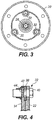
- FIGS. 2 and 3 are cross-sectional side and front views, respectively, of shear section 18.
- Shear section 18 includes a region of shaft 12 attached to annular coupling flange 20.
- Coupling flange 20 attaches to drive device 14, shown schematically in FIG. 2 , on a side opposite shaft 12, either directly or through additional intervening components.
- Coupling flange 20 includes shoulder portion 22 and neck portion 24 extending axially away from shoulder portion 22.
- Shoulder portion 22 includes an annular, flat surface through which fasteners can be extended to join coupling flange 20 to shaft 12, as is described in greater detail below.
- neck portion 24 is an elongated annular structure situated concentrically within shaft 12.
- Shear section 18 further includes stud 26 integral to or otherwise fixedly attached to shaft 12. A portion of stud 26 extends into neck portion 24 such that stud 26 is concentric with neck portion 24.
- Anti-flail bearing 28 is disposed over stud 26 and is retained over stud 26 by anti-flail nut 30.
- Anti-flail bearing 28 can be, in an exemplary embodiment, a roller bearing, but in other embodiments, can be configured as a plain bearing or a bushing, to name a few, non-limiting examples.
- Shaft 12 and coupling flange 20 can be formed from a metal alloy, such as steel or titanium. Other suitable metallic materials are contemplated herein. Shaft 12 and coupling flange 20 can, but do not have to be formed from the same material. Shaft 12 and/or coupling flange 20 can further be manufactured using a machining process, such as milling or turning, to create the various features of shear section 18 and shaft assembly 10.
- Shaft 12 can be attached to coupling flange 20 using a plurality of shear bolts 32.
- Bolts 32 (only one of which is fully shown in FIG. 2 ) extend axially through shoulder portion 22 and flanged connection region 34 of shaft 12.
- FIG. 3 bolts 32 are disposed symmetrically around coupling flange 20.
- a slight gap 36 remains between shoulder portion 22 and flanged connection region 34, which can accommodate wear ring 38.
- wear ring 38 can be separable ring or a coating, depending on the embodiment.
- FIG. 3 shows three bolts 32, other embodiments can include two, or more than three symmetrically arranged bolts 32.
- other suitable fasteners aside from bolts e.g., screws, studs, etc.
- FIG. 4 is an enlarged cross-sectional view of a bolt 32, shown for simplicity without many of the components of shear section 18.
- bolt 32 includes head 40 and shank 42.
- Shank 42 includes necked-down region 44, designed to be the "weak point" or point of torsional failure for shear section 18 of shaft assembly 10.
- Each bolt 32 within shear section 18 includes an identical necked-down region 44.
- Bolts 32 form a joint in single shear (at necked-down region 44) between shoulder portion 22 and flanged connection region 34.
- Bolts 32 can be formed from a metallic material, and can be threaded using a rolling or cutting process.
- Necked-down region can be formed in shank 42 using a grinding process followed by one or more rounds of polishing. Other machining processes are contemplated herein.
- drive device 14 can be rotationally connected to shear section 18 via coupling flange 20.
- Coupling flange 20 is rotationally connected to shaft 12 with bolts 32.
- shaft 12 disconnects from coupling flange 20 such that the two are no longer rotationally connected, which helps reduce or prevent damage to drive device 14 and/or driven device 16.
- the disconnection of shaft 12 from coupling flange 20 can cause a flailing event in which the unsupported (broken) end of shaft 12 experiences a radial displacement that can damage nearby components.
- This displacement can be controlled by anti-flail bearing 28, secured to shaft 12 via stud 26, along with neck portion 24 of coupling flange 20. Even after the disconnection of shaft 12 from coupling flange 20, neck portion 24 surrounds and radially contains anti-flail bearing 28, thus preventing substantial radial displacement of shaft 12.
- Wear ring 38 can also help prevent secondary damage to the components within or near shaft assembly 10 after an overload event. Although shaft 12 can radially disconnect from coupling flange 20 during an overload event, the two may still remain in close enough proximity to rub together while drive device 14 and coupling flange 20 continue to rotate. This can cause damage to shaft 12 and/or coupling flange 20, as well as create sparks or other debris from the metal-on-metal contact. Wear ring 38, formed from low friction coefficient material (relative to the components of shaft assembly 10), is disposed between coupling flange 20 and shaft 12 to prevent frictional damage.
- wear ring 28 can occupy some or all of gap 36 between should portion 22 and flanged connection region 34, and can further surround necked-down region 44 of each bolt 32.
- wear ring 38 is an annular ring mechanically attached to flanged connection region 34.
- wear ring 38 can instead be attached to shoulder portion 22, or can be held in place by interference fit.
- wear ring 38 can alternatively be a coating applied to flanged connection region 34 and/or shoulder portion 22.
- Suitable materials from wear ring 38 include copper alloys like brass and bronze, but generally any low-friction material can be used. Material selection can be based upon, for example, the materials used to form shaft 12 and coupling flange 20.
- shear section 18 allows shaft 12 to swiftly and rotationally disconnect from coupling flange 20 to prevent damage to drive device 14.
- Anti-flail bearing 28 and neck portion 24 inhibit radial displacement of the disconnected end of shaft 12 to prevent damage to other components.
- Shear section 18 can be modified for use in various types of shaft assemblies by varying the total area of bolts 32. Potential applications of shear section 18 include drive/transmission assemblies in aerospace (rotorcraft and fixed wing aircraft), automotive, marine, and other transportation industries, and generally for any rotatable assembly requiring protection from torsional overload events.
- a shear section for a rotating arrangement includes an axially-extending shaft having a connection flange and a coupling flange adjacent the connection flange.
- the coupling flange includes an annular shoulder portion and an elongated neck portion extending axially away from the shoulder portion and disposed concentrically within the shaft.
- the shear section further includes a plurality of fasteners extending axially through the shoulder portion and the connection flange, and securing the shaft to the coupling flange.
- Each of the plurality of fasteners includes a shank region and a reduced thickness portion circumscribing the shank region.
- the above shear section can-further includes a stud secured to the shaft and disposed concentrically with and radially inside the elongated neck portion.
- the above shear section further includes a bearing and a retaining nut surrounding a portion of the stud within the elongated neck portion.
- the shear section of the preceding paragraph can optionally include, additionally and/or alternatively, any one or more of the following features, configurations and/or additional components:
- the wherein the elongated neck portion and the bearing comprise an anti-flail feature form an anti-flail feature.
- any of the above shear sections can further include a gap between the shoulder portion and the connection flange.
- any of the above shear sections can further include a wear ring disposed within the gap.
- the wear ring can further surround the reduced thickness portions of each of the plurality of fasteners.
- the wear ring can be formed from a low-friction material.
- the shaft and the coupling flange can be formed from a metallic material.
- the plurality of fasteners can be symmetrically disposed around the shoulder portion.
- a shaft assembly for connecting a drive device to a driven device includes an axially-extending shaft configured to attach to the driven device at a first end, the shaft further including a second end opposite the first end, and a shear section located at the second end.
- the shear section includes an annular connection flange and a coupling flange adjacent the connection flange.
- the coupling flange includes an annular shoulder portion and an elongated neck portion extending axially away from the shoulder portion and disposed concentrically within the shaft.
- the coupling flange is further configured to attach to the drive device.
- the shear section further includes a plurality of fasteners extending axially through the shoulder portion and the connection flange, and securing the shaft to the connection flange. Each of the plurality of fasteners includes a shank region and a reduced thickness portion circumscribing the shank region.
- the above shaft assembly further includes a stud secured to the shaft and disposed concentrically with and radially inside the elongated neck portion.
- the above shaft assembly further includes a bearing and a retaining nut surrounding a portion of the stud within the elongated neck portion.
- the shaft assembly of the preceding paragraph can optionally include, additionally and/or alternatively, any one or more of the following features, configurations and/or additional components:
- the wherein the elongated neck portion and the bearing comprise an anti-flail feature form an anti-flail feature.
- Any of the above shaft assemblies can further include a gap between the shoulder portion and the connection flange.
- Any of the above shaft assemblies can further include a wear ring disposed within the gap.
- the wear ring can further surround the reduced thickness portions of each of the plurality of fasteners.
- the wear ring can be formed from a low-friction material.
- the shaft and the coupling flange can be formed from a metallic material.
- a method of servicing a shear section of a rotating arrangement includes replacing a plurality of existing fasteners with a plurality of replacement fasteners, such that the plurality of replacement fasteners secures a shaft to a coupling flange of the shear section.
- Each of the plurality of replacement fasteners includes a shank region and a reduced thickness portion circumscribing the shank region.
Landscapes
- Engineering & Computer Science (AREA)
- General Engineering & Computer Science (AREA)
- Mechanical Engineering (AREA)
- Shafts, Cranks, Connecting Bars, And Related Bearings (AREA)
Claims (10)
- Scherungsquerschnitt (18) für drehende Anordnung, wobei der Scherungsquerschnitt Folgendes umfasst:eine axial verlaufende Welle (12), die einen Verbindungsflansch aufweist;einen Kupplungsflansch (20) benachbart zu dem Verbindungsflansch, wobei der Kupplungsflansch (20) Folgendes umfasst:einen ringförmigen Leistenabschnitt (22);einen länglichen Stutzenabschnitt (24), der axial weg von dem Leistenabschnitt (22) verläuft und konzentrisch innerhalb der Welle (12) angeordnet ist; undeine Vielzahl von Befestigungselementen, die sich axial durch den Leistenabschnitt (22) und den Verbindungsflansch erstreckt und die Welle (12) an dem Kupplungsflansch (20) sichert;wobei jedes der Vielzahl von Befestigungselementen einen Schaftbereich (42) und einen Abschnitt mit reduzierter Dicke, der den Schaftbereich (42) abgrenzt, umfasst, gekennzeichnet durcheinen Bolzen (26), der an der Welle (12) gesichert und konzentrisch mit und radial innerhalb des länglichen Stutzenabschnitts (24) des Kupplungsflansches angeordnet ist;ein Lager (28) und eine Sicherungsmutter (30), die einen Abschnitt des Bolzens (26) innerhalb des länglichen Stutzenabschnitts (24) des Kupplungsflansches umgeben.
- Scherungsquerschnitt nach Anspruch 1, wobei der längliche Stutzenabschnitt (24) und das Lager (28) ein Merkmal gegen Ausschlagen umfassen.
- Scherungsquerschnitt nach Anspruch 1 oder 2, ferner umfassend: einen Spalt (36) zwischen dem Leistenabschnitt (22) und dem Verbindungsflansch.
- Scherungsquerschnitt nach Anspruch 3 und ferner umfassend: einen Verschleißschutzring (38), der innerhalb des Spalts (36) angeordnet ist.
- Scherungsquerschnitt nach Anspruch 4, wobei der Verschleißschutzring (38) ferner die Abschnitte mit reduzierter Dicke jedes der Vielzahl von Befestigungselementen umgibt.
- Scherungsquerschnitt nach Anspruch 4, wobei der Verschleißschutzring (38) aus einem reibungsarmen Material ausgebildet ist.
- Scherungsquerschnitt nach einem der vorstehenden Ansprüche, wobei die Welle (12) und der Kupplungsflansch (20) aus einem metallischen Material ausgebildet sind.
- Scherungsquerschnitt nach einem der vorstehenden Ansprüche, wobei die Vielzahl von Befestigungselementen symmetrisch um den Leistenabschnitt (22) angeordnet ist.
- Wellenbaugruppe zum Verbinden einer Antriebsvorrichtung mit einer angetriebenen Vorrichtung, wobei die Wellenbaugruppe Folgendes umfasst:eine axial verlaufende Welle (12), die dazu konfiguriert ist, an einem ersten Ende an der angetriebenen Vorrichtung befestigt zu sein, wobei die Welle ferner ein zweites Ende gegenüber dem ersten Ende umfasst;einen Scherungsquerschnitt (18) nach einem der vorstehenden Ansprüche, der sich an dem zweiten Ende befindet.
- Verfahren zum Warten eines Scherungsquerschnitts für eine drehende Anordnung nach Anspruch 1, wobei das Verfahren Folgendes umfasst:Ersetzen einer Vielzahl von vorhandenen Befestigungselementen mit einer Vielzahl von Ersatzbefestigungselementen, sodass die Vielzahl von Ersatzbefestigungselementen eine Welle an einem Kupplungsflansch des Scherungsquerschnitts sichert;wobei jedes der Vielzahl von Ersatzbefestigungselementen einen Schaftbereich und einen Abschnitt mit reduzierter Dicke, der den Schaftbereich abgrenzt, umfasst.
Applications Claiming Priority (1)
| Application Number | Priority Date | Filing Date | Title |
|---|---|---|---|
| US15/905,196 US10760619B2 (en) | 2018-02-26 | 2018-02-26 | Shaft shear section |
Publications (2)
| Publication Number | Publication Date |
|---|---|
| EP3530972A1 EP3530972A1 (de) | 2019-08-28 |
| EP3530972B1 true EP3530972B1 (de) | 2021-01-06 |
Family
ID=65365868
Family Applications (1)
| Application Number | Title | Priority Date | Filing Date |
|---|---|---|---|
| EP19156217.2A Active EP3530972B1 (de) | 2018-02-26 | 2019-02-08 | Wellenscherungsquerschnitt |
Country Status (2)
| Country | Link |
|---|---|
| US (1) | US10760619B2 (de) |
| EP (1) | EP3530972B1 (de) |
Families Citing this family (1)
| Publication number | Priority date | Publication date | Assignee | Title |
|---|---|---|---|---|
| DE102021202487A1 (de) * | 2021-03-15 | 2022-09-15 | Zf Friedrichshafen Ag | Luftfahrtantriebssystem eines Fluggerätes |
Family Cites Families (8)
| Publication number | Priority date | Publication date | Assignee | Title |
|---|---|---|---|---|
| US1439380A (en) * | 1921-03-31 | 1922-12-19 | Herbert C Ryding | Lead spindle |
| CA747130A (en) | 1964-07-23 | 1966-11-29 | M. Potter Frederick | Shaft disconnect |
| GB1520416A (en) * | 1974-09-27 | 1978-08-09 | Miles H P | Torque-limiting couplings |
| CA2252178C (en) | 1998-10-29 | 2007-08-14 | 648560 Alberta Ltd. (Trading As Power Train Savers) | Drive shaft coupling device |
| US6676526B1 (en) | 2000-10-17 | 2004-01-13 | Bell Helicopter Textron, Inc. | Coupling anti-flail cup |
| GB2384160B (en) | 2002-01-18 | 2004-12-08 | Spearhead Machinery Ltd | A rotary implement |
| US8366556B2 (en) | 2010-09-10 | 2013-02-05 | Sonnax Industries, Inc. | Apparatus and method for limiting torque transmitted by elongate driving and driven members |
| US9997875B2 (en) * | 2016-03-15 | 2018-06-12 | Carlisle Interconnect Technologies, Inc. | Connector and cable with torque-limiting features |
-
2018
- 2018-02-26 US US15/905,196 patent/US10760619B2/en active Active
-
2019
- 2019-02-08 EP EP19156217.2A patent/EP3530972B1/de active Active
Non-Patent Citations (1)
| Title |
|---|
| None * |
Also Published As
| Publication number | Publication date |
|---|---|
| EP3530972A1 (de) | 2019-08-28 |
| US10760619B2 (en) | 2020-09-01 |
| US20190264752A1 (en) | 2019-08-29 |
Similar Documents
| Publication | Publication Date | Title |
|---|---|---|
| US10066552B2 (en) | One degree-of-constraint semi-fusible gearbox mounting link | |
| EP2199573B1 (de) | Generatorkupplung zur Verwendung mit Gasturbinenmotor | |
| EP3242005B1 (de) | Getriebeaufhängungsverbindung sowie Verfahren zur Aufhängung eines Getriebes an eine Gasturbine | |
| US5494138A (en) | Aircraft brake torque transfer assembly | |
| EP2612043B1 (de) | Anordnung einer sicherungsmutter | |
| EP2282066B1 (de) | Haltemutter | |
| EP2565398B1 (de) | Wellenanordnung für einen gasturbinenmotor | |
| CA2997701C (en) | Driveshaft clamping assembly | |
| EP3023663B1 (de) | Thermische trennanordnung mit flugsteuerung-permanentmagnetgenerator für integrierten antriebsgenerator | |
| EP3530972B1 (de) | Wellenscherungsquerschnitt | |
| EP2831434B1 (de) | Einen Träger enthaltendes Kugellager | |
| EP2646699B1 (de) | Verschleisserkennungsvorrichtung für lagerverschleiss | |
| EP0617206B1 (de) | Selbstjustierende Mutter | |
| EP2503171A2 (de) | Lastkopplung für Stromerzeugungssysteme | |
| US2969661A (en) | Shear pin unit for flexible coupling | |
| CN115355260B (zh) | 一种用于膜盘联轴器的轴线辅助维持机构 | |
| WO2014141941A1 (ja) | 風力発電装置用の一方向クラッチ及び風力発電装置 | |
| US10995800B2 (en) | Flexible coupling for a drive system | |
| EP3263933B1 (de) | Senkgewindelager und installationsverfahren | |
| US20160265577A1 (en) | Bushing retention of threaded fastener | |
| GB2582433A (en) | Spherical ball joint | |
| EP3839280B1 (de) | Lageranordnungen, getriebeanordnungen und verfahren zur herstellung von lageranordnungen für getriebeanordnungen | |
| CN117780810A (zh) | 一种联轴器过载保护装置 | |
| CN214661453U (zh) | 一种轴及松子脱粒机 | |
| EP4015856B1 (de) | Stellglied für heckrotor |
Legal Events
| Date | Code | Title | Description |
|---|---|---|---|
| PUAI | Public reference made under article 153(3) epc to a published international application that has entered the european phase |
Free format text: ORIGINAL CODE: 0009012 |
|
| STAA | Information on the status of an ep patent application or granted ep patent |
Free format text: STATUS: THE APPLICATION HAS BEEN PUBLISHED |
|
| AK | Designated contracting states |
Kind code of ref document: A1 Designated state(s): AL AT BE BG CH CY CZ DE DK EE ES FI FR GB GR HR HU IE IS IT LI LT LU LV MC MK MT NL NO PL PT RO RS SE SI SK SM TR |
|
| AX | Request for extension of the european patent |
Extension state: BA ME |
|
| STAA | Information on the status of an ep patent application or granted ep patent |
Free format text: STATUS: REQUEST FOR EXAMINATION WAS MADE |
|
| 17P | Request for examination filed |
Effective date: 20191126 |
|
| RBV | Designated contracting states (corrected) |
Designated state(s): AL AT BE BG CH CY CZ DE DK EE ES FI FR GB GR HR HU IE IS IT LI LT LU LV MC MK MT NL NO PL PT RO RS SE SI SK SM TR |
|
| GRAP | Despatch of communication of intention to grant a patent |
Free format text: ORIGINAL CODE: EPIDOSNIGR1 |
|
| STAA | Information on the status of an ep patent application or granted ep patent |
Free format text: STATUS: GRANT OF PATENT IS INTENDED |
|
| INTG | Intention to grant announced |
Effective date: 20200811 |
|
| RIN1 | Information on inventor provided before grant (corrected) |
Inventor name: KING, MICHAEL |
|
| GRAS | Grant fee paid |
Free format text: ORIGINAL CODE: EPIDOSNIGR3 |
|
| GRAA | (expected) grant |
Free format text: ORIGINAL CODE: 0009210 |
|
| STAA | Information on the status of an ep patent application or granted ep patent |
Free format text: STATUS: THE PATENT HAS BEEN GRANTED |
|
| AK | Designated contracting states |
Kind code of ref document: B1 Designated state(s): AL AT BE BG CH CY CZ DE DK EE ES FI FR GB GR HR HU IE IS IT LI LT LU LV MC MK MT NL NO PL PT RO RS SE SI SK SM TR |
|
| REG | Reference to a national code |
Ref country code: GB Ref legal event code: FG4D |
|
| REG | Reference to a national code |
Ref country code: AT Ref legal event code: REF Ref document number: 1352695 Country of ref document: AT Kind code of ref document: T Effective date: 20210115 Ref country code: CH Ref legal event code: EP |
|
| REG | Reference to a national code |
Ref country code: DE Ref legal event code: R096 Ref document number: 602019002013 Country of ref document: DE |
|
| REG | Reference to a national code |
Ref country code: IE Ref legal event code: FG4D |
|
| REG | Reference to a national code |
Ref country code: NL Ref legal event code: MP Effective date: 20210106 |
|
| REG | Reference to a national code |
Ref country code: AT Ref legal event code: MK05 Ref document number: 1352695 Country of ref document: AT Kind code of ref document: T Effective date: 20210106 |
|
| REG | Reference to a national code |
Ref country code: LT Ref legal event code: MG9D |
|
| PG25 | Lapsed in a contracting state [announced via postgrant information from national office to epo] |
Ref country code: LT Free format text: LAPSE BECAUSE OF FAILURE TO SUBMIT A TRANSLATION OF THE DESCRIPTION OR TO PAY THE FEE WITHIN THE PRESCRIBED TIME-LIMIT Effective date: 20210106 Ref country code: PT Free format text: LAPSE BECAUSE OF FAILURE TO SUBMIT A TRANSLATION OF THE DESCRIPTION OR TO PAY THE FEE WITHIN THE PRESCRIBED TIME-LIMIT Effective date: 20210506 Ref country code: NO Free format text: LAPSE BECAUSE OF FAILURE TO SUBMIT A TRANSLATION OF THE DESCRIPTION OR TO PAY THE FEE WITHIN THE PRESCRIBED TIME-LIMIT Effective date: 20210406 Ref country code: GR Free format text: LAPSE BECAUSE OF FAILURE TO SUBMIT A TRANSLATION OF THE DESCRIPTION OR TO PAY THE FEE WITHIN THE PRESCRIBED TIME-LIMIT Effective date: 20210407 Ref country code: HR Free format text: LAPSE BECAUSE OF FAILURE TO SUBMIT A TRANSLATION OF THE DESCRIPTION OR TO PAY THE FEE WITHIN THE PRESCRIBED TIME-LIMIT Effective date: 20210106 Ref country code: FI Free format text: LAPSE BECAUSE OF FAILURE TO SUBMIT A TRANSLATION OF THE DESCRIPTION OR TO PAY THE FEE WITHIN THE PRESCRIBED TIME-LIMIT Effective date: 20210106 Ref country code: BG Free format text: LAPSE BECAUSE OF FAILURE TO SUBMIT A TRANSLATION OF THE DESCRIPTION OR TO PAY THE FEE WITHIN THE PRESCRIBED TIME-LIMIT Effective date: 20210406 |
|
| PG25 | Lapsed in a contracting state [announced via postgrant information from national office to epo] |
Ref country code: SE Free format text: LAPSE BECAUSE OF FAILURE TO SUBMIT A TRANSLATION OF THE DESCRIPTION OR TO PAY THE FEE WITHIN THE PRESCRIBED TIME-LIMIT Effective date: 20210106 Ref country code: AT Free format text: LAPSE BECAUSE OF FAILURE TO SUBMIT A TRANSLATION OF THE DESCRIPTION OR TO PAY THE FEE WITHIN THE PRESCRIBED TIME-LIMIT Effective date: 20210106 Ref country code: LV Free format text: LAPSE BECAUSE OF FAILURE TO SUBMIT A TRANSLATION OF THE DESCRIPTION OR TO PAY THE FEE WITHIN THE PRESCRIBED TIME-LIMIT Effective date: 20210106 Ref country code: RS Free format text: LAPSE BECAUSE OF FAILURE TO SUBMIT A TRANSLATION OF THE DESCRIPTION OR TO PAY THE FEE WITHIN THE PRESCRIBED TIME-LIMIT Effective date: 20210106 Ref country code: PL Free format text: LAPSE BECAUSE OF FAILURE TO SUBMIT A TRANSLATION OF THE DESCRIPTION OR TO PAY THE FEE WITHIN THE PRESCRIBED TIME-LIMIT Effective date: 20210106 |
|
| PG25 | Lapsed in a contracting state [announced via postgrant information from national office to epo] |
Ref country code: IS Free format text: LAPSE BECAUSE OF FAILURE TO SUBMIT A TRANSLATION OF THE DESCRIPTION OR TO PAY THE FEE WITHIN THE PRESCRIBED TIME-LIMIT Effective date: 20210506 |
|
| REG | Reference to a national code |
Ref country code: DE Ref legal event code: R097 Ref document number: 602019002013 Country of ref document: DE |
|
| REG | Reference to a national code |
Ref country code: BE Ref legal event code: MM Effective date: 20210228 |
|
| PG25 | Lapsed in a contracting state [announced via postgrant information from national office to epo] |
Ref country code: SM Free format text: LAPSE BECAUSE OF FAILURE TO SUBMIT A TRANSLATION OF THE DESCRIPTION OR TO PAY THE FEE WITHIN THE PRESCRIBED TIME-LIMIT Effective date: 20210106 Ref country code: CZ Free format text: LAPSE BECAUSE OF FAILURE TO SUBMIT A TRANSLATION OF THE DESCRIPTION OR TO PAY THE FEE WITHIN THE PRESCRIBED TIME-LIMIT Effective date: 20210106 Ref country code: EE Free format text: LAPSE BECAUSE OF FAILURE TO SUBMIT A TRANSLATION OF THE DESCRIPTION OR TO PAY THE FEE WITHIN THE PRESCRIBED TIME-LIMIT Effective date: 20210106 Ref country code: MC Free format text: LAPSE BECAUSE OF FAILURE TO SUBMIT A TRANSLATION OF THE DESCRIPTION OR TO PAY THE FEE WITHIN THE PRESCRIBED TIME-LIMIT Effective date: 20210106 Ref country code: LU Free format text: LAPSE BECAUSE OF NON-PAYMENT OF DUE FEES Effective date: 20210208 |
|
| PLBE | No opposition filed within time limit |
Free format text: ORIGINAL CODE: 0009261 |
|
| STAA | Information on the status of an ep patent application or granted ep patent |
Free format text: STATUS: NO OPPOSITION FILED WITHIN TIME LIMIT |
|
| PG25 | Lapsed in a contracting state [announced via postgrant information from national office to epo] |
Ref country code: SK Free format text: LAPSE BECAUSE OF FAILURE TO SUBMIT A TRANSLATION OF THE DESCRIPTION OR TO PAY THE FEE WITHIN THE PRESCRIBED TIME-LIMIT Effective date: 20210106 Ref country code: RO Free format text: LAPSE BECAUSE OF FAILURE TO SUBMIT A TRANSLATION OF THE DESCRIPTION OR TO PAY THE FEE WITHIN THE PRESCRIBED TIME-LIMIT Effective date: 20210106 Ref country code: DK Free format text: LAPSE BECAUSE OF FAILURE TO SUBMIT A TRANSLATION OF THE DESCRIPTION OR TO PAY THE FEE WITHIN THE PRESCRIBED TIME-LIMIT Effective date: 20210106 |
|
| 26N | No opposition filed |
Effective date: 20211007 |
|
| PG25 | Lapsed in a contracting state [announced via postgrant information from national office to epo] |
Ref country code: ES Free format text: LAPSE BECAUSE OF FAILURE TO SUBMIT A TRANSLATION OF THE DESCRIPTION OR TO PAY THE FEE WITHIN THE PRESCRIBED TIME-LIMIT Effective date: 20210106 Ref country code: AL Free format text: LAPSE BECAUSE OF FAILURE TO SUBMIT A TRANSLATION OF THE DESCRIPTION OR TO PAY THE FEE WITHIN THE PRESCRIBED TIME-LIMIT Effective date: 20210106 Ref country code: IE Free format text: LAPSE BECAUSE OF NON-PAYMENT OF DUE FEES Effective date: 20210208 |
|
| PG25 | Lapsed in a contracting state [announced via postgrant information from national office to epo] |
Ref country code: SI Free format text: LAPSE BECAUSE OF FAILURE TO SUBMIT A TRANSLATION OF THE DESCRIPTION OR TO PAY THE FEE WITHIN THE PRESCRIBED TIME-LIMIT Effective date: 20210106 |
|
| PG25 | Lapsed in a contracting state [announced via postgrant information from national office to epo] |
Ref country code: IT Free format text: LAPSE BECAUSE OF FAILURE TO SUBMIT A TRANSLATION OF THE DESCRIPTION OR TO PAY THE FEE WITHIN THE PRESCRIBED TIME-LIMIT Effective date: 20210106 |
|
| PG25 | Lapsed in a contracting state [announced via postgrant information from national office to epo] |
Ref country code: IS Free format text: LAPSE BECAUSE OF FAILURE TO SUBMIT A TRANSLATION OF THE DESCRIPTION OR TO PAY THE FEE WITHIN THE PRESCRIBED TIME-LIMIT Effective date: 20210506 |
|
| PG25 | Lapsed in a contracting state [announced via postgrant information from national office to epo] |
Ref country code: BE Free format text: LAPSE BECAUSE OF NON-PAYMENT OF DUE FEES Effective date: 20210228 |
|
| REG | Reference to a national code |
Ref country code: CH Ref legal event code: PL |
|
| PG25 | Lapsed in a contracting state [announced via postgrant information from national office to epo] |
Ref country code: LI Free format text: LAPSE BECAUSE OF NON-PAYMENT OF DUE FEES Effective date: 20220228 Ref country code: CH Free format text: LAPSE BECAUSE OF NON-PAYMENT OF DUE FEES Effective date: 20220228 |
|
| P01 | Opt-out of the competence of the unified patent court (upc) registered |
Effective date: 20230521 |
|
| PG25 | Lapsed in a contracting state [announced via postgrant information from national office to epo] |
Ref country code: NL Free format text: LAPSE BECAUSE OF NON-PAYMENT OF DUE FEES Effective date: 20210206 Ref country code: CY Free format text: LAPSE BECAUSE OF FAILURE TO SUBMIT A TRANSLATION OF THE DESCRIPTION OR TO PAY THE FEE WITHIN THE PRESCRIBED TIME-LIMIT Effective date: 20210106 |
|
| PG25 | Lapsed in a contracting state [announced via postgrant information from national office to epo] |
Ref country code: HU Free format text: LAPSE BECAUSE OF FAILURE TO SUBMIT A TRANSLATION OF THE DESCRIPTION OR TO PAY THE FEE WITHIN THE PRESCRIBED TIME-LIMIT; INVALID AB INITIO Effective date: 20190208 |
|
| PG25 | Lapsed in a contracting state [announced via postgrant information from national office to epo] |
Ref country code: MK Free format text: LAPSE BECAUSE OF FAILURE TO SUBMIT A TRANSLATION OF THE DESCRIPTION OR TO PAY THE FEE WITHIN THE PRESCRIBED TIME-LIMIT Effective date: 20210106 |
|
| PG25 | Lapsed in a contracting state [announced via postgrant information from national office to epo] |
Ref country code: TR Free format text: LAPSE BECAUSE OF FAILURE TO SUBMIT A TRANSLATION OF THE DESCRIPTION OR TO PAY THE FEE WITHIN THE PRESCRIBED TIME-LIMIT Effective date: 20210106 |
|
| PG25 | Lapsed in a contracting state [announced via postgrant information from national office to epo] |
Ref country code: MT Free format text: LAPSE BECAUSE OF FAILURE TO SUBMIT A TRANSLATION OF THE DESCRIPTION OR TO PAY THE FEE WITHIN THE PRESCRIBED TIME-LIMIT Effective date: 20210106 |
|
| PGFP | Annual fee paid to national office [announced via postgrant information from national office to epo] |
Ref country code: GB Payment date: 20260121 Year of fee payment: 8 |
|
| PGFP | Annual fee paid to national office [announced via postgrant information from national office to epo] |
Ref country code: DE Payment date: 20260121 Year of fee payment: 8 |
|
| PGFP | Annual fee paid to national office [announced via postgrant information from national office to epo] |
Ref country code: FR Payment date: 20260121 Year of fee payment: 8 |