EP3023627A1 - Kraftstoffinjektor - Google Patents
Kraftstoffinjektor Download PDFInfo
- Publication number
- EP3023627A1 EP3023627A1 EP15190399.4A EP15190399A EP3023627A1 EP 3023627 A1 EP3023627 A1 EP 3023627A1 EP 15190399 A EP15190399 A EP 15190399A EP 3023627 A1 EP3023627 A1 EP 3023627A1
- Authority
- EP
- European Patent Office
- Prior art keywords
- region
- fuel injector
- electrode
- sensor element
- fuel
- Prior art date
- Legal status (The legal status is an assumption and is not a legal conclusion. Google has not performed a legal analysis and makes no representation as to the accuracy of the status listed.)
- Granted
Links
Images

Classifications
-
- F—MECHANICAL ENGINEERING; LIGHTING; HEATING; WEAPONS; BLASTING
- F02—COMBUSTION ENGINES; HOT-GAS OR COMBUSTION-PRODUCT ENGINE PLANTS
- F02M—SUPPLYING COMBUSTION ENGINES IN GENERAL WITH COMBUSTIBLE MIXTURES OR CONSTITUENTS THEREOF
- F02M57/00—Fuel-injectors combined or associated with other devices
- F02M57/005—Fuel-injectors combined or associated with other devices the devices being sensors
-
- F—MECHANICAL ENGINEERING; LIGHTING; HEATING; WEAPONS; BLASTING
- F02—COMBUSTION ENGINES; HOT-GAS OR COMBUSTION-PRODUCT ENGINE PLANTS
- F02M—SUPPLYING COMBUSTION ENGINES IN GENERAL WITH COMBUSTIBLE MIXTURES OR CONSTITUENTS THEREOF
- F02M51/00—Fuel-injection apparatus characterised by being operated electrically
- F02M51/005—Arrangement of electrical wires and connections, e.g. wire harness, sockets, plugs; Arrangement of electronic control circuits in or on fuel injection apparatus
-
- G—PHYSICS
- G01—MEASURING; TESTING
- G01L—MEASURING FORCE, STRESS, TORQUE, WORK, MECHANICAL POWER, MECHANICAL EFFICIENCY, OR FLUID PRESSURE
- G01L23/00—Devices or apparatus for measuring or indicating or recording rapid changes, such as oscillations, in the pressure of steam, gas, or liquid; Indicators for determining work or energy of steam, internal-combustion, or other fluid-pressure engines from the condition of the working fluid
- G01L23/08—Devices or apparatus for measuring or indicating or recording rapid changes, such as oscillations, in the pressure of steam, gas, or liquid; Indicators for determining work or energy of steam, internal-combustion, or other fluid-pressure engines from the condition of the working fluid operated electrically
- G01L23/10—Devices or apparatus for measuring or indicating or recording rapid changes, such as oscillations, in the pressure of steam, gas, or liquid; Indicators for determining work or energy of steam, internal-combustion, or other fluid-pressure engines from the condition of the working fluid operated electrically by pressure-sensitive members of the piezoelectric type
-
- G—PHYSICS
- G01—MEASURING; TESTING
- G01L—MEASURING FORCE, STRESS, TORQUE, WORK, MECHANICAL POWER, MECHANICAL EFFICIENCY, OR FLUID PRESSURE
- G01L9/00—Measuring steady of quasi-steady pressure of fluid or fluent solid material by electric or magnetic pressure-sensitive elements; Transmitting or indicating the displacement of mechanical pressure-sensitive elements, used to measure the steady or quasi-steady pressure of a fluid or fluent solid material, by electric or magnetic means
- G01L9/0041—Transmitting or indicating the displacement of flexible diaphragms
- G01L9/008—Transmitting or indicating the displacement of flexible diaphragms using piezoelectric devices
-
- F—MECHANICAL ENGINEERING; LIGHTING; HEATING; WEAPONS; BLASTING
- F02—COMBUSTION ENGINES; HOT-GAS OR COMBUSTION-PRODUCT ENGINE PLANTS
- F02M—SUPPLYING COMBUSTION ENGINES IN GENERAL WITH COMBUSTIBLE MIXTURES OR CONSTITUENTS THEREOF
- F02M2200/00—Details of fuel-injection apparatus, not otherwise provided for
- F02M2200/24—Fuel-injection apparatus with sensors
- F02M2200/247—Pressure sensors
-
- F—MECHANICAL ENGINEERING; LIGHTING; HEATING; WEAPONS; BLASTING
- F02—COMBUSTION ENGINES; HOT-GAS OR COMBUSTION-PRODUCT ENGINE PLANTS
- F02M—SUPPLYING COMBUSTION ENGINES IN GENERAL WITH COMBUSTIBLE MIXTURES OR CONSTITUENTS THEREOF
- F02M2200/00—Details of fuel-injection apparatus, not otherwise provided for
- F02M2200/80—Fuel injection apparatus manufacture, repair or assembly
- F02M2200/8038—Fuel injection apparatus manufacture, repair or assembly the assembly involving use of adhesives, glue or the like
Definitions
- the invention relates to a fuel injector, in particular a common rail injector.
- a fuel injector which has a measuring device in the region of an injector or a holding body, which serves to detect the position of a nozzle needle designed as an injection member, in particular their closing time.
- This should, in particular over the operating life of the fuel injector considered due to wear or other circumstances always optimal adjustment of the control of the fuel injector can be achieved so that an internal combustion engine, for example, can always achieve optimum exhaust emissions.
- a designed as a piezoelectric element sensor element is glued to the surface of the injector.
- the location of the piezoelectric element is in the immediate vicinity of a high-pressure space of the fuel injector with fuel under high pressure supply bore, in the region of the wall thickness of the injector is reduced. As a result, a deformation region is formed, which bulges more elastically outward, the greater the fuel pressure in the supply bore.
- expansions or tensile stresses are generated via the piezoelectric element glued in the area of the deformation region and transmitted via the adhesive layer into the piezoelement, which leads to a corresponding voltage signal of the piezoelectric element which can be evaluated by means of an evaluation circuit in order thereby to check the fuel pressure to close in the supply bore and thereby on the closing and opening time of the nozzle needle. Details regarding the design of the piezoelectric element, in particular with regard to the arrangement of the two electrodes of the piezoelectric element and their electrical contacting are not apparent from the mentioned document.
- the invention has the object, a fuel injector, in particular a common rail injector, such form that a maximum resolution or a maximum sensor signal of the piezoelectric element can be achieved, the size of the piezoelectric element to be minimized should.
- a fuel injector in particular a common rail injector, such form that a maximum resolution or a maximum sensor signal of the piezoelectric element can be achieved, the size of the piezoelectric element to be minimized should.
- a relatively small recess is required for receiving the piezoelement on the fuel injector.
- a fuel injector with the features of claim 1 essentially by the fact that the two electrodes of the piezoelectric element are arranged on the side facing away from the fuel injector side of the piezoelectric element in partial overlap, wherein in the overlap region of the two electrodes, the two electrodes at least partially , are preferably arranged completely electrically isolated from each other.
- the advantage is achieved that the maximum ceramic or electrode surface is available for generating a stress due to an expansion in the piezoelectric element.
- the size of the piezoelectric element is minimized in terms of the required base area in that the fuel injector facing electrode protrudes laterally at least substantially not over the base of the ceramic of the piezoelectric element by the overlap with the other electrode. It is only necessary to extend the electrode facing the fuel injector by means of an intermediate or connecting portion in the direction of the other electrode and there to deform or bend over against the other electrode to form the overlap region with the other electrode.
- the two electrodes are arranged on the side facing away from the deformation region of the sensor element at least substantially parallel to each other, and that the overlap region is a partial surface of the surface of the second electrode.
- an insulation element is arranged between the two electrodes in the overlapping area.
- the insulating element can either be a separate component or element, or it can be an element which is an integral part of one of the two electrodes and is formed, for example, by a coating.
- the second electrode on the The deformation region or injector side facing away from the sensor element is arranged at least almost completely over the entire surface in operative connection with the insulating element.
- the insulation element has a recess for electrical contacting of the second electrode in a region arranged outside the covering region ,
- the insulation element is designed in the form of a coating.
- a relatively thin insulation element can be achieved, so that the overall height of the sensor element is at least essentially not increased compared with the prior art, and secondly, the attachment or positioning of an insulation element during installation is unnecessary, if this is provided as a separate or separate element Loose part would be formed, and would have to be connected for example via an adhesive bond with the electrodes.
- connection point between the deformation region and the sensor element can be arranged in a region relatively distant from the combustion chamber.
- lower temperatures prevail during operation of the internal combustion engine than in a region of the injector housing which is close to the combustion chamber.
- the connection between the addressed components thermally relatively little claimed.
- a structural design of the deformation region in the region of a blind-hole-shaped depression or a flattening of the injector housing is preferred. Both variants can manufacture particularly simple and accurate manufacture and also allow in a relatively simple manner the formation of a flat surface for connection of the sensor element.
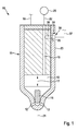
- the Indian Fig. 1 fuel injector 10 shown greatly simplified is designed as a so-called common rail injector, and is used to inject fuel into the combustion chamber, not shown, of an internal combustion engine, in particular a self-igniting internal combustion engine.
- the fuel injector 10 has an essentially made of metal, possibly multi-part design injector housing 11, in which on the combustion chamber of the internal combustion engine side facing at least one, preferably a plurality of injection openings 12 are arranged for injecting the fuel.
- this forms a high pressure chamber 15, in which a nozzle needle 16 serving as an injection member is arranged in a liftable manner in the direction of the double arrow 17.
- a nozzle needle 16 serving as an injection member is arranged in a liftable manner in the direction of the double arrow 17.
- this forms together with the inner wall of the high-pressure chamber 15 and the injector 11 a sealing seat, so that the injection openings 12 are at least indirectly closed, such that the injection of fuel from the high-pressure chamber 15 in the Combustion chamber of the internal combustion engine is avoided.
- the nozzle needle 16 In the other, not shown, lifted from the sealing seat position of the nozzle needle 16, this releases the injection openings 12 for injecting the fuel into the combustion chamber of the internal combustion engine.
- the movement of the nozzle needle 16, in particular for releasing the injection openings 12, takes place in a manner known per se by means of an actuator, not shown, which can be actuated via a voltage supply line 18 by a control device of the internal combustion engine.
- the actuator may in particular be a magnetic actuator or else a piezoactuator.
- the supply bore 19 is also connected via a fuel connection, not shown, with a fuel line 22, which in turn is coupled to a fuel reservoir 25 (rail).
- axially relatively far-spaced portion of the injector 11 is in the outer wall 23 by way of example a blind hole-shaped recess 24 (FIG. Fig. 1 and 3 ), so that the wall thickness of the injector housing 11 is reduced in the region of the recess 24.
- the injector housing 11 may also have a flattening, in the region of which the wall thickness of the injector housing 11 is reduced.
- the flat bottom 26 of the recess 24 forms part of a deformation region 27.
- the injector 11 is arranged for example in operative connection with a branch 28, which in turn opens into the supply hole 19.
- the fuel pressure currently prevailing in the supply bore 19 also acts in the injector housing 11 on the side facing away from the recess 24.
- the wall section 29 of the injector housing 11 acts on the recess 24 facing side as a deformation region 27 in the manner of an elastically deformable membrane, wherein the deformation, which forms as a curvature, the higher the instantaneous fuel pressure in the supply bore 19 or the branch 28 is, the greater.
- the fuel injector 10 has a measuring device 30.
- the measuring device 30 comprises a sensor element 32 designed as a piezo element 31.
- the piezoelectric element 31 is connected to the deformation region 27 via a material connection in the form of an adhesive connection 34.
- the cross section of the piezoelectric element 31 is at least substantially circular or round.
- the piezo element 31 has at its two opposite end faces in each case an electrode 35, 36, wherein the deformation region 27 facing electrode 35 acts as a cathode example and is connected via the adhesive joint 34 with the deformation region 27.
- a disk 37 made of ceramic material is arranged between the two electrodes 35, 36.
- the two electrodes 35, 36 each cover the entire end face of the piezoelectric element 31 and the ceramic disc 37.
- the deformation region 27 facing electrode 35 is formed on one side over the cross section of the disc 37 on one side extended and a vertical to the deformation region 27 arranged intermediate portion 38 against the top of the second electrode 36 by means of a Maisierabitess 39 by a deformation process such as bending folded.
- an overlapping area 40 which is a partial area of the second electrode 36, with the contacting portion 39 of the first electrode 35 and the second electrode 36 being arranged in the overlapping area 40 in parallel with each other.
- an insulation element 45 is arranged in the covering region 40 of the two electrodes 35, 36 and covers the covering region 40 at least partially, preferably completely.
- the insulating element 45 which electrically isolates or separates the two electrodes 35, 36 from one another, can be a separate component made of an electrically nonconductive material, or else an electrically non-conductive coating which is disposed on one of the two electrodes 35, 36, at least in the covering area 40, is applied.
- the insulating member 45 is formed in the form of a coating 46, in such a way that the coating 46 is applied to the second electrode 36 in approximately semicircular.
- the coating 46 is not only arranged in the covering region 40, but also on both sides of the rounding contacting section 39 of the electrode 35.
- the electrical contacting of the two electrodes 35, 36 takes place on the one hand via the contact section 39 of the electrode 35, and on the other hand in the Area of the electrode 36, in which no coating 46 is provided.
- the electrical contacting can be done for example by welded, soldered or bonded wires, or by spring contacts. Since this is known from the prior art per se and not essential to the invention, this is not shown in the figures.
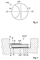
- the piezoelectric element 31 a differs from the piezoelectric element 31 in that the coating 46 a is applied over the entire surface of the second electrode 36, with the exception of an exemplary circular recess 47 for electrical contacting of the second electrode 36.
- the deformation region 27 elastically deforms outward as a function of the fuel pressure prevailing in the supply bore 19. This deformation is transmitted via the adhesive joint 34 to the piezoelectric element 31, 31 a and there generates depending on the deformation or the tensile stresses electrical voltages that can be used by means of a suitable evaluation circuit, at least indirectly to a position of the nozzle needle 16 in the injector 11 close.
- the fuel injector 10 described so far can be modified or modified in many different ways without deviating from the idea of the invention, in particular the shape or structure of the piezoelectric element 31, 31a may deviate from the illustrated embodiments.
- a Insulation element 45 is arranged, which serves that the entire surface of the two electrodes 35, 36 of the detection of the deformations of the deformation region 27 can serve.
- the insulation element 45 or the coating 46, 46a is arranged or formed only in a partial region of the covering region 40.
Landscapes
- Engineering & Computer Science (AREA)
- Chemical & Material Sciences (AREA)
- Combustion & Propulsion (AREA)
- Mechanical Engineering (AREA)
- General Engineering & Computer Science (AREA)
- Physics & Mathematics (AREA)
- General Physics & Mathematics (AREA)
- Analytical Chemistry (AREA)
- Fuel-Injection Apparatus (AREA)
Abstract
Description
- Die Erfindung betrifft einen Kraftstoffinjektor, insbesondere einen Common-Rail-Injektor. Aus der nachveröffentlichten
DE 10 2014 209 330 A1 der Anmelderin ist ein Kraftstoffinjektor bekannt, der im Bereich eines Injektorgehäuses bzw. eines Haltekörpers eine Messeinrichtung aufweist, die dazu dient, die Stellung eines als Düsennadel ausgebildeten Einspritzglieds, insbesondere deren Schließzeitpunkt, zu erfassen. Dadurch soll, insbesondere über die Betriebsdauer des Kraftstoffinjektors betrachtet, aufgrund von Verschleiß oder sonstigen Umständen eine stets optimale Anpassung der Steuerung des Kraftstoffinjektors erzielt werden, damit eine Brennkraftmaschine beispielsweise stets optimale Abgaswerte erreichen kann. Hierzu ist es bei dem bekannten Kraftstoffinjektor vorgesehen, dass ein als Piezoelement ausgebildetes Sensorelement mit der Oberfläche des Injektorgehäuses verklebt ist. Der Ort des Piezoelements befindet sich in unmittelbarer Umgebung einer einen Hochdruckraum des Kraftstoffinjektors mit unter Hochdruck stehendem Kraftstoff versorgenden Versorgungsbohrung, in deren Bereich die Wanddicke des Injektorgehäuses reduziert ist. Dadurch wird ein Verformungsbereich ausgebildet, der sich umso mehr elastisch nach außen wölbt, je größer der Kraftstoffdruck in der Versorgungsbohrung ist. Über das im Bereich des Verformungsbereichs aufgeklebte Piezoelement werden in Abhängigkeit von der Verformung Dehnungen bzw. Zugspannungen erzeugt und über die Klebstoffschicht in das Piezoelement übertragen, was zu einem entsprechenden Spannungssignal des Piezoelements führt, das mittels einer Auswerteschaltung ausgewertet werden kann, um damit auf den Kraftstoffdruck in der Versorgungsbohrung und dadurch auf den Schließ- und Öffnungszeitpunkt der Düsennadel zu schließen. Einzelheiten bezüglich der Ausbildung des Piezoelements, insbesondere hinsichtlich der Anordnung der beiden Elektroden des Piezoelements und deren elektrischer Kontaktierung sind der erwähnten Schrift nicht zu entnehmen. - Ausgehend von dem dargestellten Stand der Technik liegt der Erfindung die Aufgabe zugrunde, einen Kraftstoffinjektor, insbesondere einen Common-Rail-Injektor, derart auszubilden, dass eine größtmögliche Auflösung bzw. ein höchstmögliches Sensorsignal des Piezoelements erzielbar ist, wobei die Baugröße des Piezoelements möglichst gering sein soll. Dadurch soll insbesondere eine relativ geringe Ausnehmung zur Aufnahme des Piezoelements am Kraftstoffinjektor benötigt werden.
- Diese Aufgabe wird erfindungsgemäß bei einem Kraftstoffinjektor mit den Merkmalen des Anspruchs 1 im Wesentlichen dadurch gelöst, dass die beiden Elektroden des Piezoelements auf der dem Kraftstoffinjektor abgewandten Seite des Piezoelements in teilweiser Überdeckung zueinander angeordnet sind, wobei im Überdeckungsbereich der beiden Elektroden die beiden Elektroden zumindest bereichsweise, vorzugsweise vollständig elektrisch voneinander isoliert angeordnet sind. Dadurch wird der Vorteil erzielt, dass die maximale Keramik- bzw. Elektrodenfläche zur Erzeugung einer Spannung infolge einer Dehnung in dem Piezoelement zur Verfügung steht. Gleichzeitig ist die Baugröße des Piezoelements hinsichtlich der benötigten Grundfläche insofern minimiert, als dass die dem Kraftstoffinjektor zugewandte Elektrode durch die Überdeckung mit der anderen Elektrode seitlich zumindest im Wesentlichen nicht über die Grundfläche der Keramik des Piezoelements hinausragt. Es ist lediglich erforderlich, die dem Kraftstoffinjektor zugewandte Elektrode mittels eines Zwischen- bzw. Verbindungsabschnitts in Richtung der anderen Elektrode zu verlängern und dort gegen die andere Elektrode umzuformen bzw. umzubiegen, um den Überdeckungsbereich mit der anderen Elektrode auszubilden.
- Vorteilhafte Weiterbildungen des erfindungsgemäßen Kraftstoffinjektors sind in den Unteransprüchen angeführt.
- Insbesondere kann es vorgesehen sein, dass die beiden Elektroden auf der dem Verformungsbereich abgewandten Seite des Sensorelements zumindest im Wesentlichen parallel zueinander angeordnet sind, und dass der Überdeckungsbereich eine Teilfläche der Fläche der zweiten Elektrode ist.
- In konstruktiver Umsetzung des Erfindungsgedankens ist es vorgesehen, dass zwischen den beiden Elektroden im Überdeckungsbereich ein Isolationselement angeordnet ist. Dabei kann es sich bei dem Isolationselement grundsätzlich entweder um ein separates Bauteil bzw. Element handeln, oder aber um ein Element, das integraler Bestandteil einer der beiden Elektroden ist, und beispielsweise durch eine Beschichtung ausgebildet ist.
- Um einerseits sicherzustellen, dass im Überdeckungsbereich der beiden Elektroden über den gesamten Überdeckungsbereich gesehen das Isolationselement vorhanden ist sowie, insbesondere beim Ausbilden des Isolationselements in Form einer Beschichtung, eine möglichst einfache Fertigung der Beschichtung zu erzielen, ist es vorgesehen, dass die zweite Elektrode auf der dem Verformungsbereich bzw. injektorseitig abgewandten Seite des Sensorelements zumindest nahezu vollflächig in Wirkverbindung mit dem Isolationselement angeordnet ist. Dadurch wird darüber hinaus gegenüber der Umgebung ein verbesserter Schutz der zweiten Elektrode gegenüber anderen elektrischen Potenzialen erzielt.
- Um trotz der die zweite Elektrode nahezu vollflächig überdeckenden Isolation eine relativ einfache elektrische Kontaktierung der zweiten Elektrode zu ermöglichen, ist es bei letztgenannter konstruktiver Ausbildung bevorzugt zusätzlich vorgesehen, dass das Isolationselement in einem außerhalb des Überdeckungsbereichs angeordneten Bereich eine Aussparung zur elektrischen Kontaktierung der zweiten Elektrode aufweist.
- Besonders vorteilhaft ist es, wenn das Isolationselement in Form einer Beschichtung ausgebildet ist. Dadurch lässt sich zum einen ein relativ dünnes Isolationselement erzielen, so dass die Bauhöhe des Sensorelements zumindest im Wesentlichen gegenüber dem Stand der Technik nicht erhöht ist, zum zweiten erübrigt sich dadurch während der Montage das Anbringen bzw. Positionieren eines Isolationselements, wenn dieses als separates bzw. loses Teil ausgebildet wäre, und beispielsweise über eine Klebeverbindung mit den Elektroden verbunden werden müsste.
- Besonders bevorzugt ist die Anordnung des Verformungsbereichs am Kraftstoffinjektor im Bereich der Versorgungsbohrung oder eines mit der Versorgungsbohrung in Wirkverbindung angeordneten Abzweigs. Dies hat den Vorteil, dass die Verbindungsstelle zwischen dem Verformungsbereich und dem Sensorelement in einem relativ brennraumfernen Bereich angeordnet werden kann. In dem insbesondere während des Betriebs der Brennkraftmaschine geringere Temperaturen herrschen als in einem relativ brennraumnahen Bereich des Injektorgehäuses. Dadurch wird insbesondere auch die Verbindung zwischen den angesprochenen Bauteilen thermisch relativ wenig beansprucht. Bei Verwendung eines Abzweigs wird darüber hinaus der besondere Vorteil erzielt, dass trotz der brennraumfernen Anordnung des Sensorelements dieses an nahezu beliebigem Ort in Umfangsrichtung des Injektorgehäuses angeordnet werden kann.
- Bevorzugt ist darüber hinaus eine konstruktive Ausbildung des Verformungsbereichs im Bereich einer sacklochförmigen Vertiefung oder einer Abflachung des Injektorgehäuses. Beide Varianten lassen sich herstellungstechnisch besonders einfach und genau herstellen und ermöglichen darüber hinaus auf relativ einfache Art und Weise die Ausbildung einer ebenen Fläche zur Anbindung des Sensorelements.
- Weitere Vorteile, Merkmale und Einzelheiten der Erfindung ergeben sich aus der nachfolgenden Beschreibung bevorzugter Ausführungsbeispiele sowie anhand der Zeichnung.
- Diese zeigt in:
- Fig. 1
- eine stark vereinfachte, teilweise geschnittene Seitenansicht eines erfindungsgemäßen Kraftstoffinjektors mit einer Messeinrichtung zur zumindest mittelbaren Erfassung des Verlaufs des Kraftstoffdrucks im Kraftstoffinjektor,
- Fig. 2
- eine Draufsicht auf ein erstes erfindungsgemäß gestaltetes Sensorelement der Messeinrichtung,
- Fig. 3
- ein Schnitt in der Ebene III-III der
Fig. 2 , - Fig. 4
- ein gegenüber
Fig. 2 abgewandeltes Sensorelement mit einer zumindest nahezu vollflächig auf einer zweiten Elektrode angeordneten Isolationsschicht in Draufsicht und - Fig. 5
- einen Schnitt in der Ebene V-V der
Fig. 4 . - Gleiche Elemente bzw. Elemente mit gleicher Funktion sind in den Figuren mit den gleichen Bezugsziffern versehen.
- Der in der
Fig. 1 stark vereinfacht dargestellte Kraftstoffinjektor 10 ist als sogenannter Common-Rail-Injektor ausgebildet, und dient dem Einspritzen von Kraftstoff in den nicht gezeigten Brennraum einer Brennkraftmaschine, insbesondere einer selbstzündenden Brennkraftmaschine. - Der Kraftstoffinjektor 10 weist ein im Wesentlichen aus Metall bestehendes, ggf. mehrteilig ausgebildetes Injektorgehäuse 11 auf, in dem auf der dem Brennraum der Brennkraftmaschine zugewandten Seite wenigstens eine, vorzugsweise mehrere Einspritzöffnungen 12 zum Einspritzen des Kraftstoffs eingeordnet sind. Innerhalb des Injektorgehäuses 11 bildet dieses einen Hochruckraum 15 aus, in dem eine als Einspritzglied dienende Düsennadel 16 in Richtung des Doppelpfeils 17 hubbeweglich angeordnet ist. In der dargestellten, abgesenkten Stellung der Düsennadel 16 bildet diese zusammen mit der Innenwand des Hochdruckraums 15 bzw. des Injektorgehäuses 11 einen Dichtsitz aus, so dass die Einspritzöffnungen 12 zumindest mittelbar verschlossen sind, derart, dass das Einspritzen von Kraftstoff aus dem Hochdruckraum 15 in den Brennraum der Brennkraftmaschine vermieden wird. In der anderen, nicht dargestellten, von dem Dichtsitz abgehobenen Position der Düsennadel 16 gibt diese die Einspritzöffnungen 12 zum Einspritzen des Kraftstoffs in den Brennraum der Brennkraftmaschine frei. Die Bewegung der Düsennadel 16, insbesondere zum Freigeben der Einspritzöffnungen 12, erfolgt auf eine an sich bekannte Art und Weise mittels eines nicht dargestellten Aktuators, der über eine Spannungsversorgungsleitung 18 von einer Steuereinrichtung der Brennkraftmaschine ansteuerbar ist. Bei dem Aktuator kann es sich insbesondere um einen Magnetaktuator oder aber um einen Piezoaktuator handeln.
- Die Versorgung des Hochdruckraums 15 mit unter Hochdruck (Systemdruck) stehendem Kraftstoff erfolgt über eine innerhalb des Injektorgehäuses 11 angeordnete bzw. in Bauteilen des Kraftstoffinjektors 10 ausgebildete Versorgungsbohrung 19, die insbesondere exzentrisch zur Längsachse 21 des Injektorgehäuses 11 in einem Randbereich des Kraftstoffinjektors 10, zumindest im Wesentlichen parallel zur Längsachse 21, verläuft. Die Versorgungsbohrung 19 ist darüber hinaus über einen nicht dargestellten Kraftstoffanschlussstutzen mit einer Kraftstoffleitung 22 verbunden, welche wiederum mit einem Kraftstoffspeicher 25 (Rail) gekoppelt ist.
- In einem von den Einspritzöffnungen 12 bzw. dem Brennraum axial relativ weit beabstandeten Bereich des Injektorgehäuses 11 ist in dessen Außenwand 23 beispielhaft eine sacklochförmige Vertiefung 24 (
Fig. 1 und3 ) ausgebildet, so dass die Wanddicke des Injektorgehäuses 11 im Bereich der Vertiefung 24 reduziert ist. Ergänzend wird erwähnt, dass anstelle einer sacklochförmigen Vertiefung 24 das Injektorgehäuse 11 auch eine Abflachung aufweisen kann, in deren Bereich die Wanddicke des Injektorgehäuses 11 reduziert ist. - Der ebene ausgebildete Grund 26 der Vertiefung 24 bildet einen Teil eines Verformungsbereichs 27 aus. Auf der der Vertiefung 24 abgewandten Seite des Injektorgehäuses 11 ist das Injektorgehäuse 11 beispielhaft in Wirkverbindung mit einem Abzweig 28 angeordnet, der wiederum in der Versorgungsbohrung 19 mündet. Dadurch wirkt der in der Versorgungsbohrung 19 augenblicklich herrschende Kraftstoffdruck auch in dem Injektorgehäuse 11 auf der der Vertiefung 24 abgewandten Seite. Dadurch, dass die Wanddicke des Injektorgehäuses 11 im Bereich der Vertiefung 24 reduziert ist, wirkt der Wandabschnitt 29 des Injektorgehäuses 11 auf der der Vertiefung 24 zugewandten Seite als Verformungsbereich 27 in Art einer elastisch verformbaren Membran, wobei die Verformung, welche sich als Wölbung ausbildet, umso größer ist, je höher der augenblickliche Kraftstoffdruck in der Versorgungsbohrung 19 bzw. dem Abzweig 28 ist.
- Zur Detektion des zeitlichen Verlaufs des Kraftstoffdrucks in dem Abzweig 28 bzw. in der Versorgungsbohrung 19 und damit auch in dem Hochdruckraum 15, welcher als Indiz für die augenblickliche Stellung der Düsennadel 16 zur Ansteuerung der Düsennadel 16 verwendet wird, weist der Kraftstoffinjektor 10 eine Messeinrichtung 30 auf. Die Messeinrichtung 30 umfasst ein als Piezoelement 31 ausgebildetes Sensorelement 32.
- Das Piezoelement 31 ist mit dem Verformungsbereich 27 über eine stoffschlüssige Verbindung in Form einer Klebeverbindung 34 verbunden. Wie insbesondere anhand der
Fig. 2 und 3 erkennbar ist, ist der Querschnitt des Piezoelements 31 zumindest im Wesentlichen kreisförmig bzw. rund. Das Piezoelement 31 weist an seinen beiden gegenüberliegenden Stirnflächen jeweils eine Elektrode 35, 36 auf, wobei die dem Verformungsbereich 27 zugewandte Elektrode 35 beispielhaft als Kathode wirkt und über die Klebeverbindung 34 mit dem Verformungsbereich 27 verbunden ist. - Zwischen den beiden Elektroden 35, 36 ist, wie an sich bekannt, eine aus keramischem Material bestehende Scheibe 37 angeordnet. Die beiden Elektroden 35, 36 überdecken jeweils die gesamte Stirnfläche des Piezoelements 31 bzw. der keramischen Scheibe 37. Zusätzlich ist die erste, dem Verformungsbereich 27 zugewandte Elektrode 35 an einer Seite über den Querschnitt der Scheibe 37 an einer Seite verlängert ausgebildet und über einen senkrecht zum Verformungsbereich 27 angeordneten Zwischenabschnitt 38 gegen die Oberseite der zweiten Elektrode 36 mittels eines Kontaktierabschnitts 39 durch einen Verformungsvorgang wie Biegen umgelegt. Zwischen dem Kontaktierabschnitt 39 der Elektrode 35 und der Elektrode 36 ist ein Überdeckungsbereich 40 ausgebildet, der eine Teilfläche der zweiten Elektrode 36 ist, wobei der Kontaktierabschnitt 39 der ersten Elektrode 35 und die zweite Elektrode 36 im Überdeckungsbereich 40 parallel zueinander angeordnet sind.
- Erfindungsgemäß ist es vorgesehen, dass im Überdeckungsbereich 40 der beiden Elektroden 35, 36 ein Isolationselement 45 angeordnet ist, das den Überdeckungsbereich 40 zumindest teilweise, vorzugsweise vollständig überdeckt. Bei dem Isolationselement 45, das die beiden Elektroden 35, 36 elektrisch voneinander isoliert bzw. trennt, kann es sich um ein separates Bauteil aus einem elektrisch nicht leitenden Material handeln, oder aber um eine elektrisch nichtleitende Beschichtung, die auf einer der beiden Elektroden 35, 36, zumindest im Überdeckungsbereich 40, aufgebracht ist.
- In dem in den
Fig. 2 und 3 dargestellten Ausführungsbeispiel ist das Isolationselement 45 in Form einer Beschichtung 46 ausgebildet, und zwar derart, dass die Beschichtung 46 auf der zweiten Elektrode 36 in etwa halbkreisförmig aufgebracht ist. Dadurch ist die Beschichtung 46 nicht nur im Überdeckungsbereich 40 angeordnet, sondern auch noch beidseitig des mit einer Rundung versehenen Kontaktierabschnitts 39 der Elektrode 35. Die elektrische Kontaktierung der beiden Elektroden 35, 36 erfolgt einerseits über den Kontaktierabschnitt 39 der Elektrode 35, und andererseits in dem Bereich der Elektrode 36, in dem keine Beschichtung 46 vorgesehen ist. Die elektrische Kontaktierung kann beispielsweise durch verschweißte, verlötete oder gebondete Drähte erfolgen, oder aber durch Federkontakte. Da dies aus dem Stand der Technik an sich bekannt und nicht erfindungswesentlich ist, ist dies in den Figuren nicht dargestellt. - In den
Fig. 4 und 5 ist ein gegenüber denFig. 2 und 3 modifiziertes Piezoelement 31 a dargestellt. Das Piezoelement 31 a unterscheidet sich von dem Piezoelement 31 dadurch, dass die Beschichtung 46a auf der zweiten Elektrode 36, mit Ausnahme einer beispielhaft runden Aussparung 47 zur elektrischen Kontaktierung der zweiten Elektrode 36, vollflächig aufgebracht ist. - Beim Betrieb des Kraftstoffinjektors 10 verformt sich der Verformungsbereich 27 in Abhängigkeit des in der Versorgungsbohrung 19 herrschenden Kraftstoffdrucks elastisch nach außen. Diese Verformung überträgt sich über die Klebeverbindung 34 auf das Piezoelement 31, 31 a und erzeugt dort in Abhängigkeit der Verformung bzw. der Zugspannungen elektrische Spannungen, die mittels einer geeigneten Auswerteschaltung dazu verwendet werden können, zumindest mittelbar auf eine Stellung der Düsennadel 16 in dem Injektorgehäuse 11 zu schließen.
- Der soweit beschriebene Kraftstoffinjektor 10 kann vielfältiger Art und Weise abgewandelt bzw. modifiziert werden, ohne vom Erfindungsgedanken abzuweichen, so kann insbesondere die Form oder der Aufbau des Piezoelements 31, 31a von den dargestellten Ausführungsformen abweichen. So ist es beispielsweise denkbar, anstelle einer Klebeverbindung 34 eine anders ausgebildete stoffschlüssige Verbindung auszubilden. Wesentlich ist lediglich, dass in einem Überdeckungsbereich 40 der beiden Elektroden 35, 36 ein Isolationselement 45 angeordnet ist, das dazu dient, dass die gesamte Fläche der beiden Elektroden 35, 36 der Detektion der Verformungen des Verformungsbereichs 27 dienen können. So kann es beispielsweise vorgesehen sein, dass das Isolationselement 45 bzw. die Beschichtung 46, 46a lediglich in einem Teilbereich des Überdeckungsbereichs 40 angeordnet bzw. ausgebildet ist.
Claims (11)
- Kraftstoffinjektor (10), insbesondere Common-Rail-Injektor, mit einem Injektorgehäuse (11), in dem ein Hochdruckraum (15) ausgebildet ist, der über eine im Injektorgehäuse (11) angeordnete Versorgungsbohrung (19) mit unter Druck stehendem Kraftstoff versorgbar ist, und mit einer Messeinrichtung (30) zur zumindest mittelbaren Erfassung des Drucks im Hochdruckraum (15) oder der Versorgungsbohrung (19), wobei die Messeinrichtung (30) dazu ausgebildet ist, eine elastische Verformung eines zumindest mittelbar mit der Versorgungsbohrung (19) oder dem Hochdruckraum (15) in Wirkverbindung angeordneten Verformungsbereichs (27) zu erfassen, wobei die Messeinrichtung (30) ein als Piezoelement (31; 31 a) ausgebildetes Sensorelement (32) mit zwei Elektroden (35, 36) aufweist, wobei das Sensorelement (32) zumindest mittelbar mit dem Verformungsbereich (27) verbunden ist, wobei eine erste Elektrode (35) auf der dem Verformungsbereich (27) abgewandten Seite des Sensorelements (32) mit einer zweiten Elektrode (36) einen Überdeckungsbereich (40) ausbildet, und wobei im Überdeckungsbereich (40) der beiden Elektroden (35, 36) diese zumindest bereichsweise, vorzugsweise vollständig elektrisch voneinander isoliert angeordnet sind.
- Kraftstoffinjektor nach Anspruch 1,
dadurch gekennzeichnet,
dass die beiden Elektroden (35, 36) auf der dem Verformungsbereich (27) abgewandten Seite des Sensorelements (32) zumindest im Wesentlichen parallel zueinander angeordnet sind, und dass der Überdeckungsbereich (40) eine Teilfläche der Fläche der zweiten Elektrode (36) ist. - Kraftstoffinjektor nach Anspruch 1 oder 2,
dadurch gekennzeichnet,
dass zwischen den beiden Elektroden (35, 36) im Überdeckungsbereich (40) ein Isolationselement (45) angeordnet ist. - Kraftstoffinjektor nach Anspruch 3,
dadurch gekennzeichnet,
dass die zweite Elektrode (36) auf der dem Verformungsbereich (27) abgewandten Seite des Sensorelements (32) zumindest nahezu vollflächig in Wirkverbindung mit dem Isolationselement (45) angeordnet ist. - Kraftstoffinjektor nach Anspruch 4,
dadurch gekennzeichnet,
dass das Isolationselement (45) in einem außerhalb des Überdeckungsbereichs (40) angeordneten Bereich eine Aussparung (47) zur elektrischen Kontaktierung der zweiten Elektrode (36) aufweist. - Kraftstoffinjektor nach einem der Ansprüche 3 bis 5,
dadurch gekennzeichnet,
dass das Isolationselement (45) als Beschichtung (46; 46a) ausgebildet ist. - Kraftstoffinjektor nach einem der Ansprüche 1 bis 6,
dadurch gekennzeichnet,
dass der Verformungsbereich (27) und das Sensorelement (32) im Verbindungsbereich jeweils eben ausgebildet sind. - Kraftstoffinjektor nach einem der Ansprüche 1 bis 7,
dadurch gekennzeichnet,
dass der Verformungsbereich (27) im Bereich der Versorgungsbohrung (19) oder eines mit der Versorgungsbohrung (19) in Wirkverbindung angeordneten Abzweigs (28) angeordnet ist. - Kraftstoffinjektor nach einem der Ansprüche 1 bis 8,
dadurch gekennzeichnet,
dass der Verformungsbereich (27) im Bereich einer sacklochförmigen Vertiefung (24) oder einer Abflachung des Injektorgehäuses (11) angeordnet ist. - Kraftstoffinjektor nach einem der Ansprüche 1 bis 9,
dadurch gekennzeichnet,
dass das Sensorelement (32) und der Verformungsbereich (27) mittels einer Klebeverbindung (34) miteinander verbunden sind. - Kraftstoffinjektor nach einem der Ansprüche 1 bis 10,
dadurch gekennzeichnet,
dass im Injektorgehäuse (11) wenigstens eine Einspritzöffnung (12) zum Einspritzen von Kraftstoff in den Brennraum einer Brennkraftmaschine ausgebildet ist, die zumindest mittelbar mit dem Hochdruckraum (15) verbundenen ist, und mit einem die wenigstens eine Einspritzöffnung (12) freigebenden oder verschließenden Einspritzglied (16).
Applications Claiming Priority (1)
| Application Number | Priority Date | Filing Date | Title |
|---|---|---|---|
| DE102014223775.0A DE102014223775A1 (de) | 2014-11-21 | 2014-11-21 | Kraftstoffinjektor |
Publications (2)
| Publication Number | Publication Date |
|---|---|
| EP3023627A1 true EP3023627A1 (de) | 2016-05-25 |
| EP3023627B1 EP3023627B1 (de) | 2021-05-12 |
Family
ID=54329475
Family Applications (1)
| Application Number | Title | Priority Date | Filing Date |
|---|---|---|---|
| EP15190399.4A Active EP3023627B1 (de) | 2014-11-21 | 2015-10-19 | Kraftstoffinjektor |
Country Status (2)
| Country | Link |
|---|---|
| EP (1) | EP3023627B1 (de) |
| DE (1) | DE102014223775A1 (de) |
Cited By (2)
| Publication number | Priority date | Publication date | Assignee | Title |
|---|---|---|---|---|
| CN111980886A (zh) * | 2020-09-21 | 2020-11-24 | 常州威图流体科技有限公司 | 一种压电微泵支承结构及气体控制装置 |
| CN115780121A (zh) * | 2022-11-10 | 2023-03-14 | 南通山剑防腐科技有限公司 | 一种自动进料的防腐喷涂用喷射装置 |
Citations (5)
| Publication number | Priority date | Publication date | Assignee | Title |
|---|---|---|---|---|
| DE1648582A1 (de) * | 1966-07-12 | 1971-04-01 | List Hans | Piezoelektrischer Messwandler |
| US4672839A (en) * | 1984-11-27 | 1987-06-16 | Ngk Spark Plug Co., Ltd. | Vibration sensor |
| EP2105602A2 (de) * | 2008-03-28 | 2009-09-30 | Denso Corporation | Kraftstoffdrucksensor/Sensormontageanordnung, Kraftstoffeinspritzvorrichtung und Drucksensorvorrichtung |
| DE102012221084A1 (de) * | 2012-11-19 | 2014-05-22 | Robert Bosch Gmbh | Drucksensor und Komponente einer Brennstoffeinspritzanlage mit einem Drucksensor |
| EP2821766A1 (de) * | 2013-06-18 | 2015-01-07 | Robert Bosch Gmbh | Sensoranordnung |
Family Cites Families (1)
| Publication number | Priority date | Publication date | Assignee | Title |
|---|---|---|---|---|
| DE102014209330A1 (de) | 2014-05-16 | 2015-11-19 | Robert Bosch Gmbh | Vorrichtung zur Erfassung des Kraftstoffdrucks für einen Kraftstoffinjektor, Kraftstoffinjektor sowie Kraftstoffzuführleitung zu einem Kraftstoffinjektor |
-
2014
- 2014-11-21 DE DE102014223775.0A patent/DE102014223775A1/de not_active Withdrawn
-
2015
- 2015-10-19 EP EP15190399.4A patent/EP3023627B1/de active Active
Patent Citations (5)
| Publication number | Priority date | Publication date | Assignee | Title |
|---|---|---|---|---|
| DE1648582A1 (de) * | 1966-07-12 | 1971-04-01 | List Hans | Piezoelektrischer Messwandler |
| US4672839A (en) * | 1984-11-27 | 1987-06-16 | Ngk Spark Plug Co., Ltd. | Vibration sensor |
| EP2105602A2 (de) * | 2008-03-28 | 2009-09-30 | Denso Corporation | Kraftstoffdrucksensor/Sensormontageanordnung, Kraftstoffeinspritzvorrichtung und Drucksensorvorrichtung |
| DE102012221084A1 (de) * | 2012-11-19 | 2014-05-22 | Robert Bosch Gmbh | Drucksensor und Komponente einer Brennstoffeinspritzanlage mit einem Drucksensor |
| EP2821766A1 (de) * | 2013-06-18 | 2015-01-07 | Robert Bosch Gmbh | Sensoranordnung |
Cited By (2)
| Publication number | Priority date | Publication date | Assignee | Title |
|---|---|---|---|---|
| CN111980886A (zh) * | 2020-09-21 | 2020-11-24 | 常州威图流体科技有限公司 | 一种压电微泵支承结构及气体控制装置 |
| CN115780121A (zh) * | 2022-11-10 | 2023-03-14 | 南通山剑防腐科技有限公司 | 一种自动进料的防腐喷涂用喷射装置 |
Also Published As
| Publication number | Publication date |
|---|---|
| EP3023627B1 (de) | 2021-05-12 |
| DE102014223775A1 (de) | 2016-05-25 |
Similar Documents
| Publication | Publication Date | Title |
|---|---|---|
| EP3018337B1 (de) | Kraftstoffinjektor | |
| EP3076002B1 (de) | Kraftstoffinjektor | |
| EP3023627B1 (de) | Kraftstoffinjektor | |
| EP3088729B1 (de) | Kraftstoffinjektor sowie vorrichtung und verfahren zur montage einer messeinrichtung | |
| EP3179090B1 (de) | Kraftstoffinjektor | |
| EP3018336B1 (de) | Kraftstoffinjektor | |
| EP3088723B1 (de) | Kraftstoffinjektor | |
| EP3023758B1 (de) | Kraftstoffinjektor | |
| DE102015211186A1 (de) | Kraftstoffinjektor | |
| EP3908743B1 (de) | Kraftstoffinjektor | |
| EP3026253B1 (de) | Kraftstoffinjektor | |
| EP3076005B1 (de) | Kraftstoffinjektor und verfahren zum herstellen eines kraftstoffinjektors | |
| EP3056724A1 (de) | Kraftstoffinjektor und verfahren zur herstellung eines piezoelements für einen kraftstoffinjektor | |
| DE102018208318A1 (de) | Kraftstoffinjektor | |
| EP3159533B1 (de) | Kraftstoffinjektor | |
| EP3176556B1 (de) | Sensorvorrichtung und kraftstoffinjektor mit einer sensorvorrichtung | |
| EP3018338A1 (de) | Kraftstoffinjektor und verfahren zum herstellen eines kraftstoffinjektors | |
| EP3109453A1 (de) | Kraftstoffinjektor | |
| EP3181890A1 (de) | Sensorvorrichtung und kraftstoffinjektor mit einer sensorvorrichtung | |
| EP3088724A1 (de) | Kraftstoffinjektor | |
| EP3112662A1 (de) | Kraftstoffinjektor | |
| DE102015224683A1 (de) | Kraftstoffinjektor |
Legal Events
| Date | Code | Title | Description |
|---|---|---|---|
| AK | Designated contracting states |
Kind code of ref document: A1 Designated state(s): AL AT BE BG CH CY CZ DE DK EE ES FI FR GB GR HR HU IE IS IT LI LT LU LV MC MK MT NL NO PL PT RO RS SE SI SK SM TR |
|
| AX | Request for extension of the european patent |
Extension state: BA ME |
|
| PUAI | Public reference made under article 153(3) epc to a published international application that has entered the european phase |
Free format text: ORIGINAL CODE: 0009012 |
|
| STAA | Information on the status of an ep patent application or granted ep patent |
Free format text: STATUS: REQUEST FOR EXAMINATION WAS MADE |
|
| 17P | Request for examination filed |
Effective date: 20161125 |
|
| RBV | Designated contracting states (corrected) |
Designated state(s): AL AT BE BG CH CY CZ DE DK EE ES FI FR GB GR HR HU IE IS IT LI LT LU LV MC MK MT NL NO PL PT RO RS SE SI SK SM TR |
|
| STAA | Information on the status of an ep patent application or granted ep patent |
Free format text: STATUS: EXAMINATION IS IN PROGRESS |
|
| 17Q | First examination report despatched |
Effective date: 20180601 |
|
| RAP1 | Party data changed (applicant data changed or rights of an application transferred) |
Owner name: ROBERT BOSCH GMBH |
|
| GRAP | Despatch of communication of intention to grant a patent |
Free format text: ORIGINAL CODE: EPIDOSNIGR1 |
|
| STAA | Information on the status of an ep patent application or granted ep patent |
Free format text: STATUS: GRANT OF PATENT IS INTENDED |
|
| INTG | Intention to grant announced |
Effective date: 20210113 |
|
| GRAS | Grant fee paid |
Free format text: ORIGINAL CODE: EPIDOSNIGR3 |
|
| GRAA | (expected) grant |
Free format text: ORIGINAL CODE: 0009210 |
|
| STAA | Information on the status of an ep patent application or granted ep patent |
Free format text: STATUS: THE PATENT HAS BEEN GRANTED |
|
| AK | Designated contracting states |
Kind code of ref document: B1 Designated state(s): AL AT BE BG CH CY CZ DE DK EE ES FI FR GB GR HR HU IE IS IT LI LT LU LV MC MK MT NL NO PL PT RO RS SE SI SK SM TR |
|
| REG | Reference to a national code |
Ref country code: GB Ref legal event code: FG4D Free format text: NOT ENGLISH |
|
| REG | Reference to a national code |
Ref country code: CH Ref legal event code: EP |
|
| REG | Reference to a national code |
Ref country code: DE Ref legal event code: R096 Ref document number: 502015014704 Country of ref document: DE |
|
| REG | Reference to a national code |
Ref country code: IE Ref legal event code: FG4D Free format text: LANGUAGE OF EP DOCUMENT: GERMAN |
|
| REG | Reference to a national code |
Ref country code: AT Ref legal event code: REF Ref document number: 1392336 Country of ref document: AT Kind code of ref document: T Effective date: 20210615 |
|
| REG | Reference to a national code |
Ref country code: LT Ref legal event code: MG9D |
|
| REG | Reference to a national code |
Ref country code: NL Ref legal event code: MP Effective date: 20210512 |
|
| PG25 | Lapsed in a contracting state [announced via postgrant information from national office to epo] |
Ref country code: HR Free format text: LAPSE BECAUSE OF FAILURE TO SUBMIT A TRANSLATION OF THE DESCRIPTION OR TO PAY THE FEE WITHIN THE PRESCRIBED TIME-LIMIT Effective date: 20210512 Ref country code: BG Free format text: LAPSE BECAUSE OF FAILURE TO SUBMIT A TRANSLATION OF THE DESCRIPTION OR TO PAY THE FEE WITHIN THE PRESCRIBED TIME-LIMIT Effective date: 20210812 Ref country code: FI Free format text: LAPSE BECAUSE OF FAILURE TO SUBMIT A TRANSLATION OF THE DESCRIPTION OR TO PAY THE FEE WITHIN THE PRESCRIBED TIME-LIMIT Effective date: 20210512 Ref country code: LT Free format text: LAPSE BECAUSE OF FAILURE TO SUBMIT A TRANSLATION OF THE DESCRIPTION OR TO PAY THE FEE WITHIN THE PRESCRIBED TIME-LIMIT Effective date: 20210512 |
|
| PG25 | Lapsed in a contracting state [announced via postgrant information from national office to epo] |
Ref country code: GR Free format text: LAPSE BECAUSE OF FAILURE TO SUBMIT A TRANSLATION OF THE DESCRIPTION OR TO PAY THE FEE WITHIN THE PRESCRIBED TIME-LIMIT Effective date: 20210813 Ref country code: IS Free format text: LAPSE BECAUSE OF FAILURE TO SUBMIT A TRANSLATION OF THE DESCRIPTION OR TO PAY THE FEE WITHIN THE PRESCRIBED TIME-LIMIT Effective date: 20210912 Ref country code: LV Free format text: LAPSE BECAUSE OF FAILURE TO SUBMIT A TRANSLATION OF THE DESCRIPTION OR TO PAY THE FEE WITHIN THE PRESCRIBED TIME-LIMIT Effective date: 20210512 Ref country code: PT Free format text: LAPSE BECAUSE OF FAILURE TO SUBMIT A TRANSLATION OF THE DESCRIPTION OR TO PAY THE FEE WITHIN THE PRESCRIBED TIME-LIMIT Effective date: 20210913 Ref country code: PL Free format text: LAPSE BECAUSE OF FAILURE TO SUBMIT A TRANSLATION OF THE DESCRIPTION OR TO PAY THE FEE WITHIN THE PRESCRIBED TIME-LIMIT Effective date: 20210512 Ref country code: NO Free format text: LAPSE BECAUSE OF FAILURE TO SUBMIT A TRANSLATION OF THE DESCRIPTION OR TO PAY THE FEE WITHIN THE PRESCRIBED TIME-LIMIT Effective date: 20210812 Ref country code: ES Free format text: LAPSE BECAUSE OF FAILURE TO SUBMIT A TRANSLATION OF THE DESCRIPTION OR TO PAY THE FEE WITHIN THE PRESCRIBED TIME-LIMIT Effective date: 20210512 Ref country code: SE Free format text: LAPSE BECAUSE OF FAILURE TO SUBMIT A TRANSLATION OF THE DESCRIPTION OR TO PAY THE FEE WITHIN THE PRESCRIBED TIME-LIMIT Effective date: 20210512 Ref country code: RS Free format text: LAPSE BECAUSE OF FAILURE TO SUBMIT A TRANSLATION OF THE DESCRIPTION OR TO PAY THE FEE WITHIN THE PRESCRIBED TIME-LIMIT Effective date: 20210512 |
|
| PG25 | Lapsed in a contracting state [announced via postgrant information from national office to epo] |
Ref country code: NL Free format text: LAPSE BECAUSE OF FAILURE TO SUBMIT A TRANSLATION OF THE DESCRIPTION OR TO PAY THE FEE WITHIN THE PRESCRIBED TIME-LIMIT Effective date: 20210512 |
|
| PG25 | Lapsed in a contracting state [announced via postgrant information from national office to epo] |
Ref country code: RO Free format text: LAPSE BECAUSE OF FAILURE TO SUBMIT A TRANSLATION OF THE DESCRIPTION OR TO PAY THE FEE WITHIN THE PRESCRIBED TIME-LIMIT Effective date: 20210512 Ref country code: SK Free format text: LAPSE BECAUSE OF FAILURE TO SUBMIT A TRANSLATION OF THE DESCRIPTION OR TO PAY THE FEE WITHIN THE PRESCRIBED TIME-LIMIT Effective date: 20210512 Ref country code: SM Free format text: LAPSE BECAUSE OF FAILURE TO SUBMIT A TRANSLATION OF THE DESCRIPTION OR TO PAY THE FEE WITHIN THE PRESCRIBED TIME-LIMIT Effective date: 20210512 Ref country code: CZ Free format text: LAPSE BECAUSE OF FAILURE TO SUBMIT A TRANSLATION OF THE DESCRIPTION OR TO PAY THE FEE WITHIN THE PRESCRIBED TIME-LIMIT Effective date: 20210512 Ref country code: EE Free format text: LAPSE BECAUSE OF FAILURE TO SUBMIT A TRANSLATION OF THE DESCRIPTION OR TO PAY THE FEE WITHIN THE PRESCRIBED TIME-LIMIT Effective date: 20210512 Ref country code: DK Free format text: LAPSE BECAUSE OF FAILURE TO SUBMIT A TRANSLATION OF THE DESCRIPTION OR TO PAY THE FEE WITHIN THE PRESCRIBED TIME-LIMIT Effective date: 20210512 |
|
| REG | Reference to a national code |
Ref country code: DE Ref legal event code: R097 Ref document number: 502015014704 Country of ref document: DE |
|
| PLBE | No opposition filed within time limit |
Free format text: ORIGINAL CODE: 0009261 |
|
| STAA | Information on the status of an ep patent application or granted ep patent |
Free format text: STATUS: NO OPPOSITION FILED WITHIN TIME LIMIT |
|
| 26N | No opposition filed |
Effective date: 20220215 |
|
| REG | Reference to a national code |
Ref country code: CH Ref legal event code: PL |
|
| PG25 | Lapsed in a contracting state [announced via postgrant information from national office to epo] |
Ref country code: IS Free format text: LAPSE BECAUSE OF FAILURE TO SUBMIT A TRANSLATION OF THE DESCRIPTION OR TO PAY THE FEE WITHIN THE PRESCRIBED TIME-LIMIT Effective date: 20210912 Ref country code: AL Free format text: LAPSE BECAUSE OF FAILURE TO SUBMIT A TRANSLATION OF THE DESCRIPTION OR TO PAY THE FEE WITHIN THE PRESCRIBED TIME-LIMIT Effective date: 20210512 |
|
| REG | Reference to a national code |
Ref country code: BE Ref legal event code: MM Effective date: 20211031 |
|
| GBPC | Gb: european patent ceased through non-payment of renewal fee |
Effective date: 20211019 |
|
| PG25 | Lapsed in a contracting state [announced via postgrant information from national office to epo] |
Ref country code: MC Free format text: LAPSE BECAUSE OF FAILURE TO SUBMIT A TRANSLATION OF THE DESCRIPTION OR TO PAY THE FEE WITHIN THE PRESCRIBED TIME-LIMIT Effective date: 20210512 |
|
| PG25 | Lapsed in a contracting state [announced via postgrant information from national office to epo] |
Ref country code: LU Free format text: LAPSE BECAUSE OF NON-PAYMENT OF DUE FEES Effective date: 20211019 Ref country code: GB Free format text: LAPSE BECAUSE OF NON-PAYMENT OF DUE FEES Effective date: 20211019 Ref country code: BE Free format text: LAPSE BECAUSE OF NON-PAYMENT OF DUE FEES Effective date: 20211031 |
|
| PG25 | Lapsed in a contracting state [announced via postgrant information from national office to epo] |
Ref country code: LI Free format text: LAPSE BECAUSE OF NON-PAYMENT OF DUE FEES Effective date: 20211031 Ref country code: CH Free format text: LAPSE BECAUSE OF NON-PAYMENT OF DUE FEES Effective date: 20211031 |
|
| PG25 | Lapsed in a contracting state [announced via postgrant information from national office to epo] |
Ref country code: IE Free format text: LAPSE BECAUSE OF NON-PAYMENT OF DUE FEES Effective date: 20211019 |
|
| REG | Reference to a national code |
Ref country code: AT Ref legal event code: MM01 Ref document number: 1392336 Country of ref document: AT Kind code of ref document: T Effective date: 20211019 |
|
| PGFP | Annual fee paid to national office [announced via postgrant information from national office to epo] |
Ref country code: FR Payment date: 20221020 Year of fee payment: 8 |
|
| PG25 | Lapsed in a contracting state [announced via postgrant information from national office to epo] |
Ref country code: AT Free format text: LAPSE BECAUSE OF NON-PAYMENT OF DUE FEES Effective date: 20211019 |
|
| PGFP | Annual fee paid to national office [announced via postgrant information from national office to epo] |
Ref country code: IT Payment date: 20221031 Year of fee payment: 8 |
|
| PG25 | Lapsed in a contracting state [announced via postgrant information from national office to epo] |
Ref country code: HU Free format text: LAPSE BECAUSE OF FAILURE TO SUBMIT A TRANSLATION OF THE DESCRIPTION OR TO PAY THE FEE WITHIN THE PRESCRIBED TIME-LIMIT; INVALID AB INITIO Effective date: 20151019 |
|
| PG25 | Lapsed in a contracting state [announced via postgrant information from national office to epo] |
Ref country code: CY Free format text: LAPSE BECAUSE OF FAILURE TO SUBMIT A TRANSLATION OF THE DESCRIPTION OR TO PAY THE FEE WITHIN THE PRESCRIBED TIME-LIMIT Effective date: 20210512 |
|
| PG25 | Lapsed in a contracting state [announced via postgrant information from national office to epo] |
Ref country code: MK Free format text: LAPSE BECAUSE OF FAILURE TO SUBMIT A TRANSLATION OF THE DESCRIPTION OR TO PAY THE FEE WITHIN THE PRESCRIBED TIME-LIMIT Effective date: 20210512 |
|
| PG25 | Lapsed in a contracting state [announced via postgrant information from national office to epo] |
Ref country code: TR Free format text: LAPSE BECAUSE OF FAILURE TO SUBMIT A TRANSLATION OF THE DESCRIPTION OR TO PAY THE FEE WITHIN THE PRESCRIBED TIME-LIMIT Effective date: 20210512 |
|
| PG25 | Lapsed in a contracting state [announced via postgrant information from national office to epo] |
Ref country code: FR Free format text: LAPSE BECAUSE OF NON-PAYMENT OF DUE FEES Effective date: 20231031 |
|
| PG25 | Lapsed in a contracting state [announced via postgrant information from national office to epo] |
Ref country code: MT Free format text: LAPSE BECAUSE OF FAILURE TO SUBMIT A TRANSLATION OF THE DESCRIPTION OR TO PAY THE FEE WITHIN THE PRESCRIBED TIME-LIMIT Effective date: 20210512 |
|
| PG25 | Lapsed in a contracting state [announced via postgrant information from national office to epo] |
Ref country code: IT Free format text: LAPSE BECAUSE OF NON-PAYMENT OF DUE FEES Effective date: 20231019 |
|
| PG25 | Lapsed in a contracting state [announced via postgrant information from national office to epo] |
Ref country code: IT Free format text: LAPSE BECAUSE OF NON-PAYMENT OF DUE FEES Effective date: 20231019 |
|
| PGFP | Annual fee paid to national office [announced via postgrant information from national office to epo] |
Ref country code: DE Payment date: 20251209 Year of fee payment: 11 |