EP3023302A2 - Couplage de support de charge - Google Patents
Couplage de support de charge Download PDFInfo
- Publication number
- EP3023302A2 EP3023302A2 EP15193669.7A EP15193669A EP3023302A2 EP 3023302 A2 EP3023302 A2 EP 3023302A2 EP 15193669 A EP15193669 A EP 15193669A EP 3023302 A2 EP3023302 A2 EP 3023302A2
- Authority
- EP
- European Patent Office
- Prior art keywords
- load carrier
- plug
- coupling
- axis
- hook
- Prior art date
- Legal status (The legal status is an assumption and is not a legal conclusion. Google has not performed a legal analysis and makes no representation as to the accuracy of the status listed.)
- Granted
Links
- 230000008878 coupling Effects 0.000 title claims abstract description 113
- 238000010168 coupling process Methods 0.000 title claims abstract description 113
- 238000005859 coupling reaction Methods 0.000 title claims abstract description 113
- 230000005540 biological transmission Effects 0.000 claims description 21
- 230000003321 amplification Effects 0.000 description 2
- 238000003199 nucleic acid amplification method Methods 0.000 description 2
- 230000015572 biosynthetic process Effects 0.000 description 1
- 230000000903 blocking effect Effects 0.000 description 1
- 239000000969 carrier Substances 0.000 description 1
- 238000005266 casting Methods 0.000 description 1
- 238000010276 construction Methods 0.000 description 1
- 230000000694 effects Effects 0.000 description 1
- 238000005755 formation reaction Methods 0.000 description 1
- 230000013011 mating Effects 0.000 description 1
- 239000007787 solid Substances 0.000 description 1
- 238000003466 welding Methods 0.000 description 1
Images


Classifications
-
- B—PERFORMING OPERATIONS; TRANSPORTING
- B60—VEHICLES IN GENERAL
- B60R—VEHICLES, VEHICLE FITTINGS, OR VEHICLE PARTS, NOT OTHERWISE PROVIDED FOR
- B60R9/00—Supplementary fittings on vehicle exterior for carrying loads, e.g. luggage, sports gear or the like
- B60R9/06—Supplementary fittings on vehicle exterior for carrying loads, e.g. luggage, sports gear or the like at vehicle front or rear
Definitions
- the invention relates to a load carrier coupling for coupling a rear load carrier to a motor vehicle, in particular a passenger car
- the load carrier clutch comprises a provided for attachment to the motor vehicle or arranged on the motor vehicle vehicle coupling element and arranged on the load carrier or provided for attachment to the load carrier load carrier coupling element in which the coupling elements comprise a plug-in part and a plug-in receptacle which can be attached to one another along a plug-in axis
- the load-carrier coupling has at least one movable form-fit body drivable by an actuation arrangement for engagement in a form-fit receptacle, wherein the form-fit body arrangement engages upon engagement of the at least one form-fit body in the form-fitting receptacle assumes a locking position and blocking removal of the coupling elements from each other with respect to the stub axle t and otherwise assumes a release position and allows removal of the coupling elements from each other.
- Such load carrier clutch is for example in EP 1 757 488 A2 explained.
- ball locks are provided on the plug projections, ie a locking pin presses form-fitting body in the form of balls radially outward into a form-fitting receptacle shape in a ball seat channel.
- the stop of this arrangement is not always optimal.
- the at least one form-fitting body forms part of a pivotable about a pivot axis arranged on a coupling element hook body which engages in the locking position for hooking along the thru axle in a hook receptacle on the other coupling element and is supported with at least one support surface on at least one abutment surface of this other coupling element transverse to the thru-axle.
- the coupling elements when they are plugged together, are optimally connected to each other due to the entanglement.
- the hook body is pivotally mounted by a simple mechanism, which simplifies the operation, but at the same time allows for optimal application of force.
- the at least one support surface ensures that the hook is not only effective so to speak on train in the direction of the thru-axle, but also across it.
- the hook body supports the coupling elements also transversely to the thru axle from each other.
- a plurality of hook body may be provided, for example, a pair of hook bodies.
- the hook bodies are expediently arranged on mutually opposite sides of the plug-in part. But they can also be arranged on opposite sides of the socket.
- the one or more hook body are arranged on an outer side of the male part and thus come to lie sandwiched between the male part and the plug-in receptacle in the locking position.
- a cavity is present, in which one or more hook body movable, namely pivotally mounted.
- the respective hook body is relatively free to move, so does not tend to jamming.
- combinations are possible, ie that, for example, at least one hook body in an interior of a Plug part and also at least one further hook body is arranged laterally outside the male part.
- the at least one support surface comprises a support surface extending parallel or substantially parallel to the plug-in axis.
- the at least one support surface comprises an inclined surface or wedge surface.
- the hook body can additionally be wedged or braced by the inclined surface.
- the at least one support surface expediently comprises mutually angular support surfaces for abutment with mutually angled abutment surfaces.
- the support surfaces are perpendicular to each other. But other angular positions are readily possible. It is for example possible that the abutment surfaces are arranged on an inner corner or on an inner corner region of the plug-in receptacle, while the associated, mutually angular support surfaces are arranged on an outer corner region or edge region of the hook body. It is understood that the mutually angular support surfaces can merge directly into each other. But it is also possible that the mutually angular support surfaces have a distance from each other. Thus, for example, it is possible that mutually angular support surfaces are arranged on opposite sides of the hook body or that are not provided between the support surfaces serving as support surfaces areas.
- the at least one support surface expediently comprises opposing first and second support surfaces, which are supported in the locking position on opposite abutment surfaces of the other coupling element.
- These support surfaces may, but need not be angular or inclined to each other.
- Support surfaces pivot in opposite directions, so to speak, in the direction of the abutment surfaces in order to abut against these or to support them.
- the support surfaces may comprise support surfaces which are point-symmetrical with respect to the pivot axis or are arranged on mutually symmetrical regions.
- the at least one support surface expediently comprises a first and a second support surface, which are arranged one behind the other with respect to the plug-in axis. This can be, for example, the two support surfaces arranged on opposite sides with respect to the pivot axis.
- the at least one hook body expediently forms a pivoting lever. Arms of the hook body preferably extend away from the pivot axis. It is preferred if an actuating arm, on which the actuating arrangement engages, is longer than a holding arm, on which the at least one form-fitting body is arranged.
- the at least one positive fit body expediently forms a hook projection of the hook body. But it is also possible that the form-fitting body is separated from a hook projection of the hook body, that is, that the hook body comprises both the positive-locking body and the hook projection.
- the at least one form-fitting body preferably projects in front of a support surface or the support surfaces of the hook body.
- the form-fitting body is integral with the hook body.
- the form-fitting body is arranged on a free end region of the hook body. It is particularly advantageous if it then integrally forms the hook projection, as it were. But it is also possible that the positive-fit body is arranged between free end regions of the hook body.
- the plug-in receptacle is arranged on the vehicle coupling element or is formed thereof.
- the plug-in part for example the plug-in projection, on the other hand, is expediently advantageously arranged on the load-carrier coupling element or essentially forms it.
- the hook body forms a pivot lever.
- the actuating arrangement expediently acts on a longitudinal end of the pivoting lever. For example, it presses on the longitudinal end of the pivot lever or is hinged thereto.
- a hook projection for example the form-fitting body, in particular the form-fitting body connected in one piece with the hook body, is then advantageously provided at the other longitudinal end of the pivot lever.
- the hook body expediently forms a clamping body for clamping the coupling elements transversely to the plug axis and by the actuating arrangement between a clamping position in which the coupling elements are clamped together, and a release position, in which the coupling elements along the plug axis are longitudinally movable relative to each other, adjustable.
- the actuating arrangement can be driven by a motor. But preferred is a simple manual operation. However, it can also be provided that the actuating arrangement is alternatively manually and motor-operated, for example, manually for emergency operation.
- a lever arrangement which forms part of the actuating arrangement or represents the actuating arrangement itself.
- the lever arrangement can be operated by a motor.
- the lever arrangement comprises at least one manually operable lever.
- the actuating arrangement comprises a transmission gear.
- the transmission gear may include, for example, a lever assembly, a gear transmission or the like.
- the transmission gear expediently acts in the sense of a power amplification of the actuating force. This is how the operating force works with greater force on the at least one positive locking element or the hook body.
- a self-contained invention represents in a load carrier coupling according to the preamble of claim 1, when it comprises an over-center mechanism with a dead center between the locking position and the release position.
- the positive connection is formed by a hooking.
- the positive connection is formed for example by the fact that the at least one form-fitting body is displaced radially outward, for example, the plug-in projection or the plug-in part in order then to engage in a form-fitting receptacle on the plug-in receptacle.
- the Kochtot Vietnamese mechanism acts on a hook body, which is provided only for hooking with respect to the plug-in axis, but not for clamping or supporting transversely to the plug-in axis, as the above-explained hook body.
- the Kochtot Vietnamese mechanism is expediently provided in connection with the at least one hook body, which acts on the one longitudinally, on the other transverse to the thru axle supporting and holding.
- the over-center mechanism comprises a lever mechanism.
- the lever mechanism preferably comprises a manually operable lever or a manually operable actuator.
- a transmission member of the over-center mechanism is suitably pivotally on the one hand on the hook body and on the other hand to an actuating lever, for example, a manually or motor-operated actuating lever, pivotably articulated.
- a pivot axis of the actuating lever and a pivot axis of the transmission member are expediently arranged on opposite sides of that coupling element, which carries the Kochtot Vietnamese mechanism.
- the coupling element carrying the actuator assembly may e.g. be the vehicle-mounted bracket.
- a manual or motorized actuating element is arranged on or in the motor vehicle in order to operate the actuating arrangement or to act on the actuating arrangement.
- the at least one hook body is arranged on a vehicle-side coupling element, in particular when the actuating arrangement is also provided on the vehicle side. In the embodiment shown in the drawing, both the actuating arrangement and the at least one hook body are provided on the load carrier-side coupling element.
- An expedient embodiment provides that the actuating arrangement can be locked and / or closed.
- a latch is provided, with which an actuating lever or other handle can be locked in the locking position.
- a lock with which the actuating lever or other actuating element can be closed is expedient. Particularly preferred is a locking or closing the Kochtot Vietnamese mechanism. It is preferably provided that in the locking position, that is beyond the dead center, a lock and / or a bolt is provided to fix the over-center mechanism stationary.
- the plug-in part and the plug-in receptacle have a polygonal shape. This is at the same time given a rotation.
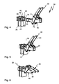
- a load carrier clutch 10 according to the drawing comprises a vehicle coupling element 20 and a load carrier coupling element 40.
- the vehicle coupling element 20 is arranged on a motor vehicle 90 (shown schematically). For example, it is supported by a cross member of a carrier assembly 91 which is disposed at a rear of the motor vehicle 90. It is preferably provided that the vehicle coupling element 20 is at least partially covered by a bumper 92 of the motor vehicle. It can also be provided that the vehicle coupling element 20 projects downwardly in front of the bumper 92.
- the load carrier coupling element 40 is arranged on a load carrier 95, which is shown schematically.
- the load carrier 95 is used for example for transporting bicycles, for transporting a transport box or the like.
- the load carrier 95 may e.g. a carrying rack, carriers for parking bicycles or the like include.
- the load carrier 95 is, for example, a male part 41, for example a male projection, integrally.
- the plug-in part 41 is used for plugging into a plug-in receptacle 21 of the vehicle coupling element 20.
- a plug-in receptacle can also be provided on the load carrier, the plug-in projection or the plug-in part on the motor vehicle.
- a system according to the invention forms a kit or a retrofit system, i. that, for example, the load carrier coupling element 40 is subsequently mounted on an existing frame or an existing support base of a load carrier.
- the load carrier coupling element 40 is subsequently mounted on an existing frame or an existing support base of a load carrier.
- the male projection or the male part 41 and the subsequently explained components of the coupling element 40 could be subsequently mounted.
- the plug-in projection or the plug-in part 41 comprises, for example, a profile 42, in particular a tubular profile, which can be inserted into the plug-in receptacle 21.
- the profile 42 or the male part 41 includes, for example, opposing side walls 43, 44 and upper wall 46 and a lower wall 45.
- the walls 43-46 are present at right angles to each other, ie they form a rectangular or preferably square profile 42.
- a polygonal profile Although in the context of the invention advantageous, but not essential. It could also, for example, round or rounded profile cross-sections of a Plug projection or plug-in part can be provided easily.
- the walls 43-46 define a cavity or interior 47, which is also an option, but not mandatory. It is conceivable that the plug-in projection or the plug-in part of a load carrier coupling according to the invention has a solid cross-section.
- the vehicle coupling element 20 comprises carrier elements 25, 26 which are fixed to the carrier arrangement 91, for example projecting upwards from the latter, this being understood only as an example, that is to say, of course, the vehicle coupling element 20 could also be downwardly, for example, in front of a crossbeam protrude.
- the support members 25, 26 carry an upper support wall 22 and a lower support wall 24, which limit the plug-in receptacle 21 above and below.
- Inner surfaces 30, 31 of the support walls 22, 24 serve to bear the upper wall 46 and the lower wall 45 of the profile 42 or the male part 41st
- the upper support wall 22 and the lower support wall 24 are connected by struts 23 or stiffened.
- the struts 23 could serve to support or receive the male part 41, but this is not provided in the present case.
- the plug-in receptacle 21, e.g. the receiving cage, is also bounded by side walls 34, which are as it were associated with the outer edges of the profile 42, but not directly support, but provide abutment surfaces for later explained hook body.
- receptacles 27 are provided, which carry the upper and lower support walls 22, 24 and the oblique side walls 34.
- the receptacles 27 form components of the plug-in receptacle 21, namely with their sections 33 extending between the upper and lower support walls 22, 24.
- pin projections 29 are provided, which engage in recesses 28 of the carrier elements 25, 26 and are held there in a form-fitting manner.
- the recesses 28 are provided, for example, on the inner corner regions of the receptacles 27, which are essentially square in cross-section corresponding to the male part 41.
- the upper and lower support walls 22, 24 are dosed or held in accordance with a form-fitting manner. They engage with projections 35, for example in the manner of pins, in receptacles 36 on the sections 32 of the receptacles 27 of the carrier elements 25, 26 which extend transversely to the sections 33.
- the vehicle coupling element 20 is formed of plate-like components. But that is only an example. It is, for example, a vehicle coupling element as a casting with corresponding polygonal formations or the like readily possible.
- the plug-in part 41 can be inserted into the plug-in receptacle 21 along a plug axis S. Is in FIG. 1 indicated.
- a positive fit body assembly 50 is used to secure against unintentional release with respect to the plug-in axis S, ie for the driving operation of the load carrier 95 in connection with the motor vehicle 90.
- the positive fit body assembly 50 comprises on the male part 41 arranged hook body 51, at the free end portions 52 hook 53rd are arranged.
- the respective hook 53 forms a form-fitting body 54 and is preferably integral with the respective hook body 51.
- the hooks engage in a form-fitting manner in hook receivers 55 on the vehicle coupling element 20.
- the hook receptacles 55 form form-fit receptacles 56.
- the hook receptacles 55 are configured as recesses 37. It is preferred if the recesses 37 and thus the hook receivers 55 are provided so that they are arranged directly next to one of the support elements or support elements 25, 26, ie adjacent to the receptacle 27 of a respective support element, so that the hook 53 not only directly the recess 37, which is provided for example on the upper or lower support member or the support wall 22, 24, supported, but also on the support member 25 or 26. In the present case, the arrangement is such that in each case a recess 37 immediately adjacent to the support member 26 at the lower support wall 24 is provided.
- support element should make it clear that the respective support wall 22, 24 need not of course be plate-like or wall-like, but this represents only an option.
- the respective hook body 51 forms a pivot lever 57, which is mounted pivotably about a pivot axis D1 on the load carrier coupling element 40.
- pivot bearing 58 on the side walls 43, 44 are provided, with which the hook body 51 or pivot lever 57 are pivotally mounted on the male part 41.
- the pivoting levers 57 each comprise a holding arm 58a, on which the at least one form-fit body 54 or the hook 53 is arranged, and an actuating arm 59, which can be actuated by an actuating arrangement 60.
- the actuator assembly 60 includes an actuating lever 61 that is manually engageable. At a free end portion 62 of the actuating lever 61, on which, for example, a handle, not shown, in particular a handle bar, may be arranged, the operating lever 61 is easily gripped by an operator.
- the operating lever 61 is rotatable about a rotational axis D3 with respect to the load carrier coupling element 40.
- the axis of rotation D3 is provided by a bearing 63 which comprises bearing blocks 64.
- pivot bearing 65 are provided on the bearing blocks 64.
- An end region 66 of the actuating lever 61 opposite the free end region 62 is pivotably mounted on the pivot bearing 65 about the axis of rotation D3.
- At least one bearing element passes through the bearing blocks 64 and corresponding bearing receptacles on the end region 66 in order to form the pivot bearing with respect to the axis of rotation D3.
- a transmission member 70 is pivotally connected about a rotational axis D4.
- a bearing pin or bearing element 71 passes through unspecified bearing receptacles of the transmission member 70 and the actuating lever 61, so that the transmission member 70 and the actuating lever 61 can rotate or pivot relative to each other about the rotation axis D4.
- the bearing pin or the bearing member 71 is provided at an end portion 72 of the transmission member 70.
- a respective other end region 73 of a respective transmission member 70 is pivotably articulated about a rotational axis D2 to a respective pivot lever 57, that is, to a respective hook body 51.
- a bearing element or bearing pin 74 passes through bearing receptacles on the end region 73 of the transmission element 70 and on the actuating arm 59, in particular its free end region. This achieves optimum leverage, i. the attack of the actuator assembly 60 to a respective pivot lever 57 or hook body 51 is carried out as far away from the pivot axis or axis of rotation D1, which allows optimal power amplification of the actuating force.
- a transmission member 70 is provided in each case.
- the actuating lever 61 is preferably formed from expediently plate-like or rod-like lever members 68 which are interconnected by a transverse strut 69. As a result, a lightweight construction is achieved.
- a bearing receiver for the bearing pin 71 At each of the lever members 68, there is provided a bearing receiver for the bearing pin 71, i.
- Each lever member 68 takes, so to speak, a transmission member 70 with or actuates this.
- the respective bearing pin or bearing element 71 engages in an abutment device 75.
- a substantially circular receiving link 76 is provided on the bearing blocks 64, into which the bearing elements 71 intervention.
- the bearing elements 71 simultaneously form stop elements of the transmission member 70.
- separate measures could be taken for this purpose, for example, projections on the transmission member 70, which engage in the receiving link 76, at least cooperate with the stop means 75.
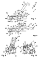
- the respective longitudinal end portions of the receiving link 76 form stops 77, 78 for the bearing element 79, so the stop member of the transmission member 70, and each limit a pivotal movement of the transmission member 70 of the in FIG. 7 shown release position L (stop 77) in the in FIG. 8 illustrated locking position V (stop 78) of the actuator assembly 60 and the form-fitting body assembly 50th
- the pivoting lever 57 and the hook body 51 thereby make a pivotal movement or rotational movement about the axis of rotation D1, in which the hook 53 from a disengaged position (release position L / FIG. 7 ) in an engaged position (locking position V / FIG. 8 ) get to the hook receptacles 55.
- the form-fitting body 54 are received positively in the form-fitting receptacles 56.
- Support surfaces 79 of the hooks 53 are then supported on abutment surfaces 80 of the recesses 37 and hook receivers 55, so that the load carrier coupling element 40 is fixed in terms of tensile strength with respect to the vehicle coupling element 20 in the direction of the stub axle S.
- the force thus acting is indicated by an arrow P1 in FIG FIG. 8 indicated.
- a stop body 81 projecting upwards in front of the plug-in part 41 to abut on the vehicle coupling element 20, for example the upper support wall, on an abutment surface 81 a ( FIG. 8 ).
- abutment body 82 may be provided, on which abuts the free end of the male member 41.
- a plug stop so to speak on train with respect to the through axle S as a stop or in the opposite direction to the effect of Hook 53 acts, is formed by a plug contact arrangement 83 of the vehicle coupling element 20 and a corresponding mating plug contact arrangement 84 of the load carrier coupling element 40, which are provided for an electrical power supply of the load carrier 95 through the electrical system of the motor vehicle 90 and electrically contacting each other can intervene.
- the plug contact arrangements 83, 84 include, for example, electrical sockets and plug-in projections.
- each hook body 51 forms a clamping body for clamping the coupling elements 20, 40 transversely to the plug-in axis S.
- FIG. 7 is a release position in which the coupling elements 20, 40 with respect to the through-axle S longitudinally movable relative to each other, shown.
- FIG. 8 In contrast, a clamping position is shown, in which the hook body 51, the plug-in part 41 in the plug-in receptacle 21 transverse to the stub axle S brace.
- the male part 41 is clamped in the plug-in receptacle 21, so to speak with respect to the pivot axis D1.
- support surfaces 87, 88 On opposite longitudinal sides 85, 86 namely clamping surfaces forming support surfaces 87, 88 are provided.
- the support surfaces 87, 88 support the hook body 51 and thus the plug-in part 41 transversely to the plug-in axis S in the plug-in receptacle 21.
- the support surfaces 87, 88 act on the insides of the oblique Side walls 34, the abutment surfaces 89 represent.
- the corresponding force or support force is indicated by arrows P2 and P3.
- the male part 41 and the coupling element 40 is supported in the respective inner corner regions of the plug-in receptacle 21 transversely to the stub axle S.
- the support surfaces 87, 88 extend at an angle or obliquely to the upper and lower support walls 22, 24 of the plug receptacle 21.
- the oblique course also relates to the profile 42 or the plug 41.
- the support surfaces 87, 88 namely extend at an angle to the outer sides of the side walls 43, 44 and the lower and upper walls 45, 46th
- the fixed clamped hold is securely held by an over-center mechanism 67 of the actuator assembly 60.
- the axis of rotation D4 is namely adjusted by the adjustment between the locking position V and the release position L on the pivot axis D3 away, which represents, so to speak, a dead center of the lever mechanism or the Kochtot Vietnamese mechanism.
- a connecting line T is this Mattertot Vietnamese in FIG. 8 recognizable to some extent.
- the distance between the pivot axes or axes of rotation D2 and D3 is the shortest. So if the locking position V ( FIG.
- an over-center mechanism can only serve to represent a reliable, secure locking.
- the over-center mechanism 67 or another over-center mechanism is adjustable.
- the axis of rotation D4 with respect to the pivot lever or actuating lever 61 is adjustable, for example, based on an in FIG. 10 shown schematically as an arrow set screw 15 so as to adjust the dead center position can.
- the bearing element for the pivot axis D4 may have some eccentricity, i. that by adjusting the bearing element, for example a bearing pin, based on a rotational movement, the position of the rotation axis D4 is adjustable.
Landscapes
- Engineering & Computer Science (AREA)
- Mechanical Engineering (AREA)
- Lock And Its Accessories (AREA)
- Fittings On The Vehicle Exterior For Carrying Loads, And Devices For Holding Or Mounting Articles (AREA)
- Electric Propulsion And Braking For Vehicles (AREA)
Applications Claiming Priority (1)
| Application Number | Priority Date | Filing Date | Title |
|---|---|---|---|
| DE102014017019.5A DE102014017019A1 (de) | 2014-11-19 | 2014-11-19 | Lastenträgerkupplung |
Publications (3)
| Publication Number | Publication Date |
|---|---|
| EP3023302A2 true EP3023302A2 (fr) | 2016-05-25 |
| EP3023302A3 EP3023302A3 (fr) | 2016-08-31 |
| EP3023302B1 EP3023302B1 (fr) | 2017-12-13 |
Family
ID=54478633
Family Applications (1)
| Application Number | Title | Priority Date | Filing Date |
|---|---|---|---|
| EP15193669.7A Active EP3023302B1 (fr) | 2014-11-19 | 2015-11-09 | Couplage de support de charge |
Country Status (2)
| Country | Link |
|---|---|
| EP (1) | EP3023302B1 (fr) |
| DE (1) | DE102014017019A1 (fr) |
Cited By (1)
| Publication number | Priority date | Publication date | Assignee | Title |
|---|---|---|---|---|
| EP3964369A1 (fr) * | 2020-09-02 | 2022-03-09 | ACPS Automotive GmbH | Système de montage |
Families Citing this family (1)
| Publication number | Priority date | Publication date | Assignee | Title |
|---|---|---|---|---|
| DE102016124563A1 (de) * | 2016-09-30 | 2018-04-05 | Westfalia-Automotive Gmbh | Anhängekupplung mit einem Stützelement |
Citations (1)
| Publication number | Priority date | Publication date | Assignee | Title |
|---|---|---|---|---|
| EP1757488A2 (fr) | 2005-08-25 | 2007-02-28 | WESTFALIA - Automotive GmbH | Structure de support pour véhicule et esemble support correspondant |
Family Cites Families (5)
| Publication number | Priority date | Publication date | Assignee | Title |
|---|---|---|---|---|
| DE4403715A1 (de) * | 1994-02-07 | 1995-08-10 | Eberhard Tittel | Anhängervorrichtung für den rückseitigen Anbau an ein Fahrzeug, insbesondere einen PKW |
| FR2823161A1 (fr) * | 2001-04-05 | 2002-10-11 | Automaxi Ind Sa | Accessoire destine a augmenter la capacite de transport d'un vehicule automobile, et application |
| SE520614C2 (sv) * | 2001-11-06 | 2003-07-29 | Thule Sweden Ab | Kopplingsanordning för en lastbärare |
| FR2867120B1 (fr) * | 2004-03-02 | 2006-04-28 | Renault Sas | Porte-charge destine a equiper l'arriere d'un vehicule automobile |
| DE102010045104B4 (de) * | 2010-09-13 | 2021-11-04 | Westfalia-Automotive Gmbh | Kupplung für ein Lastenträger-System |
-
2014
- 2014-11-19 DE DE102014017019.5A patent/DE102014017019A1/de not_active Withdrawn
-
2015
- 2015-11-09 EP EP15193669.7A patent/EP3023302B1/fr active Active
Patent Citations (1)
| Publication number | Priority date | Publication date | Assignee | Title |
|---|---|---|---|---|
| EP1757488A2 (fr) | 2005-08-25 | 2007-02-28 | WESTFALIA - Automotive GmbH | Structure de support pour véhicule et esemble support correspondant |
Cited By (2)
| Publication number | Priority date | Publication date | Assignee | Title |
|---|---|---|---|---|
| EP3964369A1 (fr) * | 2020-09-02 | 2022-03-09 | ACPS Automotive GmbH | Système de montage |
| US12049183B2 (en) | 2020-09-02 | 2024-07-30 | ACPS Automotive GmbH | Mounting system |
Also Published As
| Publication number | Publication date |
|---|---|
| DE102014017019A1 (de) | 2016-05-19 |
| EP3023302B1 (fr) | 2017-12-13 |
| EP3023302A3 (fr) | 2016-08-31 |
Similar Documents
| Publication | Publication Date | Title |
|---|---|---|
| EP1757488B1 (fr) | Structure de support pour véhicule | |
| DE102006013465B4 (de) | Kupplungsvorrichtung für einen Lastenträger zum Anschluss an eine Kugelkopf-Anhängerkupplung eines Fahrzeugs | |
| EP2428404B1 (fr) | Système de support de charges | |
| DE102012213104A1 (de) | Containerverriegelung | |
| DE102005040182A1 (de) | Trägeranordnung für ein Kraftfahrzeug und Halteranordnung dafür | |
| EP0645296A1 (fr) | Chariot à main en forme de chariot à ridelles | |
| WO2012100929A1 (fr) | Attelage de remorque | |
| EP2479045B1 (fr) | Système de support de charges | |
| DE102016103596A1 (de) | Lastenträgerkupplung | |
| EP3023302B1 (fr) | Couplage de support de charge | |
| DE102014011348A1 (de) | Anhängekupplung mit einem Baukastensystem | |
| EP2623375B1 (fr) | Support de toit | |
| DE102004011003B4 (de) | Sperrsystem zur Ladungssicherung | |
| EP2712839A2 (fr) | Châssis de changement d'outil | |
| EP2829422B1 (fr) | Système d'attelage pour véhicules automobiles | |
| DE102010045104A1 (de) | Kupplung für ein Lastenträger-System | |
| EP1619079A2 (fr) | Dispositif pour le portage de charges en extérieur d'un véhicule | |
| EP2428403B1 (fr) | Couplage pour un système de support de charge doté d'une unité de contact | |
| EP2428410A2 (fr) | Support de plaque minéralogique | |
| DE202009015075U1 (de) | Kupplungslader | |
| DE202008008860U1 (de) | Adapter für die Befestigung eines Stehbrettes an einem Buggy, Kinder- und/oder Einkaufswagen | |
| DE20101312U1 (de) | Vorrichtung zum Sichern von Ladegut auf der Ladefläche eines Fahrzeuges | |
| WO2023284919A1 (fr) | Remorque de véhicule | |
| DE3531326C1 (en) | Rope guide window | |
| DE202012102046U1 (de) | Fahrgestell, System sowie Sortiment |
Legal Events
| Date | Code | Title | Description |
|---|---|---|---|
| AK | Designated contracting states |
Kind code of ref document: A2 Designated state(s): AL AT BE BG CH CY CZ DE DK EE ES FI FR GB GR HR HU IE IS IT LI LT LU LV MC MK MT NL NO PL PT RO RS SE SI SK SM TR |
|
| AX | Request for extension of the european patent |
Extension state: BA ME |
|
| PUAI | Public reference made under article 153(3) epc to a published international application that has entered the european phase |
Free format text: ORIGINAL CODE: 0009012 |
|
| PUAL | Search report despatched |
Free format text: ORIGINAL CODE: 0009013 |
|
| AK | Designated contracting states |
Kind code of ref document: A3 Designated state(s): AL AT BE BG CH CY CZ DE DK EE ES FI FR GB GR HR HU IE IS IT LI LT LU LV MC MK MT NL NO PL PT RO RS SE SI SK SM TR |
|
| AX | Request for extension of the european patent |
Extension state: BA ME |
|
| RIC1 | Information provided on ipc code assigned before grant |
Ipc: B60D 1/52 20060101ALI20160728BHEP Ipc: B60R 9/06 20060101AFI20160728BHEP |
|
| 17P | Request for examination filed |
Effective date: 20170213 |
|
| RBV | Designated contracting states (corrected) |
Designated state(s): AL AT BE BG CH CY CZ DE DK EE ES FI FR GB GR HR HU IE IS IT LI LT LU LV MC MK MT NL NO PL PT RO RS SE SI SK SM TR |
|
| GRAP | Despatch of communication of intention to grant a patent |
Free format text: ORIGINAL CODE: EPIDOSNIGR1 |
|
| INTG | Intention to grant announced |
Effective date: 20170628 |
|
| GRAS | Grant fee paid |
Free format text: ORIGINAL CODE: EPIDOSNIGR3 |
|
| GRAA | (expected) grant |
Free format text: ORIGINAL CODE: 0009210 |
|
| GRAT | Correction requested after decision to grant or after decision to maintain patent in amended form |
Free format text: ORIGINAL CODE: EPIDOSNCDEC |
|
| REG | Reference to a national code |
Ref country code: GB Ref legal event code: FG4D Free format text: NOT ENGLISH |
|
| REG | Reference to a national code |
Ref country code: AT Ref legal event code: REF Ref document number: 954030 Country of ref document: AT Kind code of ref document: T Effective date: 20171215 Ref country code: CH Ref legal event code: EP |
|
| REG | Reference to a national code |
Ref country code: IE Ref legal event code: FG4D Free format text: LANGUAGE OF EP DOCUMENT: GERMAN |
|
| REG | Reference to a national code |
Ref country code: DE Ref legal event code: R096 Ref document number: 502015002567 Country of ref document: DE |
|
| REG | Reference to a national code |
Ref country code: NL Ref legal event code: MP Effective date: 20171213 |
|
| PG25 | Lapsed in a contracting state [announced via postgrant information from national office to epo] |
Ref country code: SE Free format text: LAPSE BECAUSE OF FAILURE TO SUBMIT A TRANSLATION OF THE DESCRIPTION OR TO PAY THE FEE WITHIN THE PRESCRIBED TIME-LIMIT Effective date: 20171213 Ref country code: NO Free format text: LAPSE BECAUSE OF FAILURE TO SUBMIT A TRANSLATION OF THE DESCRIPTION OR TO PAY THE FEE WITHIN THE PRESCRIBED TIME-LIMIT Effective date: 20180313 Ref country code: FI Free format text: LAPSE BECAUSE OF FAILURE TO SUBMIT A TRANSLATION OF THE DESCRIPTION OR TO PAY THE FEE WITHIN THE PRESCRIBED TIME-LIMIT Effective date: 20171213 |
|
| PG25 | Lapsed in a contracting state [announced via postgrant information from national office to epo] |
Ref country code: BG Free format text: LAPSE BECAUSE OF FAILURE TO SUBMIT A TRANSLATION OF THE DESCRIPTION OR TO PAY THE FEE WITHIN THE PRESCRIBED TIME-LIMIT Effective date: 20180313 Ref country code: LV Free format text: LAPSE BECAUSE OF FAILURE TO SUBMIT A TRANSLATION OF THE DESCRIPTION OR TO PAY THE FEE WITHIN THE PRESCRIBED TIME-LIMIT Effective date: 20171213 Ref country code: GR Free format text: LAPSE BECAUSE OF FAILURE TO SUBMIT A TRANSLATION OF THE DESCRIPTION OR TO PAY THE FEE WITHIN THE PRESCRIBED TIME-LIMIT Effective date: 20180314 Ref country code: RS Free format text: LAPSE BECAUSE OF FAILURE TO SUBMIT A TRANSLATION OF THE DESCRIPTION OR TO PAY THE FEE WITHIN THE PRESCRIBED TIME-LIMIT Effective date: 20171213 Ref country code: HR Free format text: LAPSE BECAUSE OF FAILURE TO SUBMIT A TRANSLATION OF THE DESCRIPTION OR TO PAY THE FEE WITHIN THE PRESCRIBED TIME-LIMIT Effective date: 20171213 |
|
| PG25 | Lapsed in a contracting state [announced via postgrant information from national office to epo] |
Ref country code: NL Free format text: LAPSE BECAUSE OF FAILURE TO SUBMIT A TRANSLATION OF THE DESCRIPTION OR TO PAY THE FEE WITHIN THE PRESCRIBED TIME-LIMIT Effective date: 20171213 |
|
| PG25 | Lapsed in a contracting state [announced via postgrant information from national office to epo] |
Ref country code: EE Free format text: LAPSE BECAUSE OF FAILURE TO SUBMIT A TRANSLATION OF THE DESCRIPTION OR TO PAY THE FEE WITHIN THE PRESCRIBED TIME-LIMIT Effective date: 20171213 Ref country code: CY Free format text: LAPSE BECAUSE OF FAILURE TO SUBMIT A TRANSLATION OF THE DESCRIPTION OR TO PAY THE FEE WITHIN THE PRESCRIBED TIME-LIMIT Effective date: 20171213 Ref country code: SK Free format text: LAPSE BECAUSE OF FAILURE TO SUBMIT A TRANSLATION OF THE DESCRIPTION OR TO PAY THE FEE WITHIN THE PRESCRIBED TIME-LIMIT Effective date: 20171213 Ref country code: CZ Free format text: LAPSE BECAUSE OF FAILURE TO SUBMIT A TRANSLATION OF THE DESCRIPTION OR TO PAY THE FEE WITHIN THE PRESCRIBED TIME-LIMIT Effective date: 20171213 Ref country code: ES Free format text: LAPSE BECAUSE OF FAILURE TO SUBMIT A TRANSLATION OF THE DESCRIPTION OR TO PAY THE FEE WITHIN THE PRESCRIBED TIME-LIMIT Effective date: 20171213 |
|
| PG25 | Lapsed in a contracting state [announced via postgrant information from national office to epo] |
Ref country code: PL Free format text: LAPSE BECAUSE OF FAILURE TO SUBMIT A TRANSLATION OF THE DESCRIPTION OR TO PAY THE FEE WITHIN THE PRESCRIBED TIME-LIMIT Effective date: 20171213 Ref country code: SM Free format text: LAPSE BECAUSE OF FAILURE TO SUBMIT A TRANSLATION OF THE DESCRIPTION OR TO PAY THE FEE WITHIN THE PRESCRIBED TIME-LIMIT Effective date: 20171213 Ref country code: IS Free format text: LAPSE BECAUSE OF FAILURE TO SUBMIT A TRANSLATION OF THE DESCRIPTION OR TO PAY THE FEE WITHIN THE PRESCRIBED TIME-LIMIT Effective date: 20180413 Ref country code: RO Free format text: LAPSE BECAUSE OF FAILURE TO SUBMIT A TRANSLATION OF THE DESCRIPTION OR TO PAY THE FEE WITHIN THE PRESCRIBED TIME-LIMIT Effective date: 20171213 Ref country code: IT Free format text: LAPSE BECAUSE OF FAILURE TO SUBMIT A TRANSLATION OF THE DESCRIPTION OR TO PAY THE FEE WITHIN THE PRESCRIBED TIME-LIMIT Effective date: 20171213 |
|
| REG | Reference to a national code |
Ref country code: DE Ref legal event code: R097 Ref document number: 502015002567 Country of ref document: DE |
|
| PG25 | Lapsed in a contracting state [announced via postgrant information from national office to epo] |
Ref country code: MT Free format text: LAPSE BECAUSE OF FAILURE TO SUBMIT A TRANSLATION OF THE DESCRIPTION OR TO PAY THE FEE WITHIN THE PRESCRIBED TIME-LIMIT Effective date: 20171213 |
|
| PLBE | No opposition filed within time limit |
Free format text: ORIGINAL CODE: 0009261 |
|
| STAA | Information on the status of an ep patent application or granted ep patent |
Free format text: STATUS: NO OPPOSITION FILED WITHIN TIME LIMIT |
|
| REG | Reference to a national code |
Ref country code: FR Ref legal event code: PLFP Year of fee payment: 4 |
|
| 26N | No opposition filed |
Effective date: 20180914 |
|
| PG25 | Lapsed in a contracting state [announced via postgrant information from national office to epo] |
Ref country code: DK Free format text: LAPSE BECAUSE OF FAILURE TO SUBMIT A TRANSLATION OF THE DESCRIPTION OR TO PAY THE FEE WITHIN THE PRESCRIBED TIME-LIMIT Effective date: 20171213 |
|
| PG25 | Lapsed in a contracting state [announced via postgrant information from national office to epo] |
Ref country code: SI Free format text: LAPSE BECAUSE OF FAILURE TO SUBMIT A TRANSLATION OF THE DESCRIPTION OR TO PAY THE FEE WITHIN THE PRESCRIBED TIME-LIMIT Effective date: 20171213 |
|
| REG | Reference to a national code |
Ref country code: CH Ref legal event code: PL |
|
| PG25 | Lapsed in a contracting state [announced via postgrant information from national office to epo] |
Ref country code: LU Free format text: LAPSE BECAUSE OF NON-PAYMENT OF DUE FEES Effective date: 20181109 Ref country code: MC Free format text: LAPSE BECAUSE OF FAILURE TO SUBMIT A TRANSLATION OF THE DESCRIPTION OR TO PAY THE FEE WITHIN THE PRESCRIBED TIME-LIMIT Effective date: 20171213 |
|
| REG | Reference to a national code |
Ref country code: BE Ref legal event code: MM Effective date: 20181130 |
|
| REG | Reference to a national code |
Ref country code: IE Ref legal event code: MM4A |
|
| PG25 | Lapsed in a contracting state [announced via postgrant information from national office to epo] |
Ref country code: CH Free format text: LAPSE BECAUSE OF NON-PAYMENT OF DUE FEES Effective date: 20181130 Ref country code: LI Free format text: LAPSE BECAUSE OF NON-PAYMENT OF DUE FEES Effective date: 20181130 |
|
| PG25 | Lapsed in a contracting state [announced via postgrant information from national office to epo] |
Ref country code: IE Free format text: LAPSE BECAUSE OF NON-PAYMENT OF DUE FEES Effective date: 20181109 |
|
| PG25 | Lapsed in a contracting state [announced via postgrant information from national office to epo] |
Ref country code: BE Free format text: LAPSE BECAUSE OF NON-PAYMENT OF DUE FEES Effective date: 20181130 |
|
| PG25 | Lapsed in a contracting state [announced via postgrant information from national office to epo] |
Ref country code: TR Free format text: LAPSE BECAUSE OF FAILURE TO SUBMIT A TRANSLATION OF THE DESCRIPTION OR TO PAY THE FEE WITHIN THE PRESCRIBED TIME-LIMIT Effective date: 20171213 |
|
| PG25 | Lapsed in a contracting state [announced via postgrant information from national office to epo] |
Ref country code: PT Free format text: LAPSE BECAUSE OF FAILURE TO SUBMIT A TRANSLATION OF THE DESCRIPTION OR TO PAY THE FEE WITHIN THE PRESCRIBED TIME-LIMIT Effective date: 20171213 |
|
| PG25 | Lapsed in a contracting state [announced via postgrant information from national office to epo] |
Ref country code: LT Free format text: LAPSE BECAUSE OF FAILURE TO SUBMIT A TRANSLATION OF THE DESCRIPTION OR TO PAY THE FEE WITHIN THE PRESCRIBED TIME-LIMIT Effective date: 20171213 Ref country code: HU Free format text: LAPSE BECAUSE OF FAILURE TO SUBMIT A TRANSLATION OF THE DESCRIPTION OR TO PAY THE FEE WITHIN THE PRESCRIBED TIME-LIMIT; INVALID AB INITIO Effective date: 20151109 Ref country code: MK Free format text: LAPSE BECAUSE OF NON-PAYMENT OF DUE FEES Effective date: 20171213 |
|
| PG25 | Lapsed in a contracting state [announced via postgrant information from national office to epo] |
Ref country code: AL Free format text: LAPSE BECAUSE OF FAILURE TO SUBMIT A TRANSLATION OF THE DESCRIPTION OR TO PAY THE FEE WITHIN THE PRESCRIBED TIME-LIMIT Effective date: 20171213 |
|
| GBPC | Gb: european patent ceased through non-payment of renewal fee |
Effective date: 20191109 |
|
| PG25 | Lapsed in a contracting state [announced via postgrant information from national office to epo] |
Ref country code: GB Free format text: LAPSE BECAUSE OF NON-PAYMENT OF DUE FEES Effective date: 20191109 |
|
| REG | Reference to a national code |
Ref country code: AT Ref legal event code: MM01 Ref document number: 954030 Country of ref document: AT Kind code of ref document: T Effective date: 20201109 |
|
| PG25 | Lapsed in a contracting state [announced via postgrant information from national office to epo] |
Ref country code: AT Free format text: LAPSE BECAUSE OF NON-PAYMENT OF DUE FEES Effective date: 20201109 |
|
| PGFP | Annual fee paid to national office [announced via postgrant information from national office to epo] |
Ref country code: FR Payment date: 20211011 Year of fee payment: 7 |
|
| PG25 | Lapsed in a contracting state [announced via postgrant information from national office to epo] |
Ref country code: FR Free format text: LAPSE BECAUSE OF NON-PAYMENT OF DUE FEES Effective date: 20221130 |
|
| PGFP | Annual fee paid to national office [announced via postgrant information from national office to epo] |
Ref country code: DE Payment date: 20231129 Year of fee payment: 9 |