EP3021056B1 - Building-integrated photovoltaic module - Google Patents
Building-integrated photovoltaic module Download PDFInfo
- Publication number
- EP3021056B1 EP3021056B1 EP14192819.2A EP14192819A EP3021056B1 EP 3021056 B1 EP3021056 B1 EP 3021056B1 EP 14192819 A EP14192819 A EP 14192819A EP 3021056 B1 EP3021056 B1 EP 3021056B1
- Authority
- EP
- European Patent Office
- Prior art keywords
- layer
- photovoltaic
- facade
- adhesive
- panel
- Prior art date
- Legal status (The legal status is an assumption and is not a legal conclusion. Google has not performed a legal analysis and makes no representation as to the accuracy of the status listed.)
- Active
Links
- 239000010410 layer Substances 0.000 claims description 258
- 239000002131 composite material Substances 0.000 claims description 41
- 239000000853 adhesive Substances 0.000 claims description 40
- 230000001070 adhesive effect Effects 0.000 claims description 40
- 230000004888 barrier function Effects 0.000 claims description 37
- 238000009434 installation Methods 0.000 claims description 37
- 239000011505 plaster Substances 0.000 claims description 23
- 238000009413 insulation Methods 0.000 claims description 21
- 239000011248 coating agent Substances 0.000 claims description 16
- 238000000576 coating method Methods 0.000 claims description 16
- 230000008878 coupling Effects 0.000 claims description 14
- 238000010168 coupling process Methods 0.000 claims description 14
- 238000005859 coupling reaction Methods 0.000 claims description 14
- 239000011241 protective layer Substances 0.000 claims description 12
- 229910052500 inorganic mineral Inorganic materials 0.000 claims description 11
- 239000011707 mineral Substances 0.000 claims description 11
- 239000000758 substrate Substances 0.000 claims description 11
- 239000004744 fabric Substances 0.000 claims description 10
- 239000000835 fiber Substances 0.000 claims description 10
- 238000013086 organic photovoltaic Methods 0.000 claims description 7
- 239000010409 thin film Substances 0.000 claims description 7
- 239000003365 glass fiber Substances 0.000 claims description 6
- 229920000728 polyester Polymers 0.000 claims description 5
- 239000011230 binding agent Substances 0.000 claims description 4
- 239000004020 conductor Substances 0.000 claims description 4
- 239000004570 mortar (masonry) Substances 0.000 claims description 4
- 239000000203 mixture Substances 0.000 claims description 3
- 229920000642 polymer Polymers 0.000 claims description 3
- 229920005594 polymer fiber Polymers 0.000 claims description 3
- 229920003043 Cellulose fiber Polymers 0.000 claims description 2
- 239000000378 calcium silicate Substances 0.000 claims description 2
- 229910052918 calcium silicate Inorganic materials 0.000 claims description 2
- OYACROKNLOSFPA-UHFFFAOYSA-N calcium;dioxido(oxo)silane Chemical compound [Ca+2].[O-][Si]([O-])=O OYACROKNLOSFPA-UHFFFAOYSA-N 0.000 claims description 2
- 238000005253 cladding Methods 0.000 claims description 2
- 239000008199 coating composition Substances 0.000 claims description 2
- 239000011490 mineral wool Substances 0.000 claims description 2
- 230000002787 reinforcement Effects 0.000 claims description 2
- 239000000126 substance Substances 0.000 claims description 2
- 239000004745 nonwoven fabric Substances 0.000 claims 2
- 239000002759 woven fabric Substances 0.000 claims 1
- 239000007789 gas Substances 0.000 description 15
- 239000012790 adhesive layer Substances 0.000 description 10
- 238000010276 construction Methods 0.000 description 10
- QVGXLLKOCUKJST-UHFFFAOYSA-N atomic oxygen Chemical compound [O] QVGXLLKOCUKJST-UHFFFAOYSA-N 0.000 description 8
- 235000010755 mineral Nutrition 0.000 description 8
- 239000001301 oxygen Substances 0.000 description 8
- 229910052760 oxygen Inorganic materials 0.000 description 8
- 206010034972 Photosensitivity reaction Diseases 0.000 description 6
- 239000000463 material Substances 0.000 description 6
- 239000002245 particle Substances 0.000 description 6
- 239000002800 charge carrier Substances 0.000 description 5
- 230000008901 benefit Effects 0.000 description 4
- 239000011521 glass Substances 0.000 description 4
- 230000010354 integration Effects 0.000 description 4
- 230000015572 biosynthetic process Effects 0.000 description 3
- 230000006378 damage Effects 0.000 description 3
- 230000006735 deficit Effects 0.000 description 3
- 238000005516 engineering process Methods 0.000 description 3
- 239000010408 film Substances 0.000 description 3
- 239000002105 nanoparticle Substances 0.000 description 3
- 229920003023 plastic Polymers 0.000 description 3
- 239000011347 resin Substances 0.000 description 3
- 229920005989 resin Polymers 0.000 description 3
- XLYOFNOQVPJJNP-UHFFFAOYSA-N water Substances O XLYOFNOQVPJJNP-UHFFFAOYSA-N 0.000 description 3
- VYPSYNLAJGMNEJ-UHFFFAOYSA-N Silicium dioxide Chemical compound O=[Si]=O VYPSYNLAJGMNEJ-UHFFFAOYSA-N 0.000 description 2
- 229920002125 Sokalan® Polymers 0.000 description 2
- GWEVSGVZZGPLCZ-UHFFFAOYSA-N Titan oxide Chemical compound O=[Ti]=O GWEVSGVZZGPLCZ-UHFFFAOYSA-N 0.000 description 2
- 150000001252 acrylic acid derivatives Chemical class 0.000 description 2
- 150000001875 compounds Chemical class 0.000 description 2
- 239000004567 concrete Substances 0.000 description 2
- 230000010339 dilation Effects 0.000 description 2
- 230000000694 effects Effects 0.000 description 2
- 238000010030 laminating Methods 0.000 description 2
- 230000007774 longterm Effects 0.000 description 2
- 238000004519 manufacturing process Methods 0.000 description 2
- TWNQGVIAIRXVLR-UHFFFAOYSA-N oxo(oxoalumanyloxy)alumane Chemical compound O=[Al]O[Al]=O TWNQGVIAIRXVLR-UHFFFAOYSA-N 0.000 description 2
- 239000004033 plastic Substances 0.000 description 2
- 239000002985 plastic film Substances 0.000 description 2
- 229920006255 plastic film Polymers 0.000 description 2
- 239000004584 polyacrylic acid Substances 0.000 description 2
- 230000001681 protective effect Effects 0.000 description 2
- 230000009467 reduction Effects 0.000 description 2
- 230000003014 reinforcing effect Effects 0.000 description 2
- 239000006120 scratch resistant coating Substances 0.000 description 2
- 239000004065 semiconductor Substances 0.000 description 2
- 229910004613 CdTe Inorganic materials 0.000 description 1
- 238000004026 adhesive bonding Methods 0.000 description 1
- 229910021417 amorphous silicon Inorganic materials 0.000 description 1
- 238000005452 bending Methods 0.000 description 1
- 230000009286 beneficial effect Effects 0.000 description 1
- 239000011449 brick Substances 0.000 description 1
- 239000004568 cement Substances 0.000 description 1
- 230000008859 change Effects 0.000 description 1
- 238000001816 cooling Methods 0.000 description 1
- 238000005336 cracking Methods 0.000 description 1
- 238000013016 damping Methods 0.000 description 1
- 230000002950 deficient Effects 0.000 description 1
- 239000006185 dispersion Substances 0.000 description 1
- 238000001035 drying Methods 0.000 description 1
- 230000005611 electricity Effects 0.000 description 1
- 239000003792 electrolyte Substances 0.000 description 1
- 238000005538 encapsulation Methods 0.000 description 1
- 238000004146 energy storage Methods 0.000 description 1
- 239000000945 filler Substances 0.000 description 1
- 239000010419 fine particle Substances 0.000 description 1
- 229910010272 inorganic material Inorganic materials 0.000 description 1
- 239000011147 inorganic material Substances 0.000 description 1
- 239000012212 insulator Substances 0.000 description 1
- 239000005001 laminate film Substances 0.000 description 1
- 239000012528 membrane Substances 0.000 description 1
- 229910052751 metal Inorganic materials 0.000 description 1
- 239000002184 metal Substances 0.000 description 1
- 238000000034 method Methods 0.000 description 1
- 230000007935 neutral effect Effects 0.000 description 1
- 238000013021 overheating Methods 0.000 description 1
- VVRQVWSVLMGPRN-UHFFFAOYSA-N oxotungsten Chemical class [W]=O VVRQVWSVLMGPRN-UHFFFAOYSA-N 0.000 description 1
- RVTZCBVAJQQJTK-UHFFFAOYSA-N oxygen(2-);zirconium(4+) Chemical compound [O-2].[O-2].[Zr+4] RVTZCBVAJQQJTK-UHFFFAOYSA-N 0.000 description 1
- 230000035515 penetration Effects 0.000 description 1
- 239000005518 polymer electrolyte Substances 0.000 description 1
- 229920002620 polyvinyl fluoride Polymers 0.000 description 1
- 238000010248 power generation Methods 0.000 description 1
- 238000003825 pressing Methods 0.000 description 1
- 239000005871 repellent Substances 0.000 description 1
- 150000003346 selenoethers Chemical class 0.000 description 1
- HBMJWWWQQXIZIP-UHFFFAOYSA-N silicon carbide Chemical compound [Si+]#[C-] HBMJWWWQQXIZIP-UHFFFAOYSA-N 0.000 description 1
- 229910010271 silicon carbide Inorganic materials 0.000 description 1
- 239000000377 silicon dioxide Substances 0.000 description 1
- 235000012239 silicon dioxide Nutrition 0.000 description 1
- 150000004772 tellurides Chemical class 0.000 description 1
- 150000003568 thioethers Chemical class 0.000 description 1
- 239000004408 titanium dioxide Substances 0.000 description 1
- 229910001930 tungsten oxide Inorganic materials 0.000 description 1
- 238000009423 ventilation Methods 0.000 description 1
- 235000014692 zinc oxide Nutrition 0.000 description 1
- RNWHGQJWIACOKP-UHFFFAOYSA-N zinc;oxygen(2-) Chemical class [O-2].[Zn+2] RNWHGQJWIACOKP-UHFFFAOYSA-N 0.000 description 1
- 229910001928 zirconium oxide Inorganic materials 0.000 description 1
Images

Classifications
-
- H—ELECTRICITY
- H02—GENERATION; CONVERSION OR DISTRIBUTION OF ELECTRIC POWER
- H02S—GENERATION OF ELECTRIC POWER BY CONVERSION OF INFRARED RADIATION, VISIBLE LIGHT OR ULTRAVIOLET LIGHT, e.g. USING PHOTOVOLTAIC [PV] MODULES
- H02S20/00—Supporting structures for PV modules
- H02S20/20—Supporting structures directly fixed to an immovable object
- H02S20/22—Supporting structures directly fixed to an immovable object specially adapted for buildings
- H02S20/26—Building materials integrated with PV modules, e.g. façade elements
-
- Y—GENERAL TAGGING OF NEW TECHNOLOGICAL DEVELOPMENTS; GENERAL TAGGING OF CROSS-SECTIONAL TECHNOLOGIES SPANNING OVER SEVERAL SECTIONS OF THE IPC; TECHNICAL SUBJECTS COVERED BY FORMER USPC CROSS-REFERENCE ART COLLECTIONS [XRACs] AND DIGESTS
- Y02—TECHNOLOGIES OR APPLICATIONS FOR MITIGATION OR ADAPTATION AGAINST CLIMATE CHANGE
- Y02A—TECHNOLOGIES FOR ADAPTATION TO CLIMATE CHANGE
- Y02A30/00—Adapting or protecting infrastructure or their operation
- Y02A30/60—Planning or developing urban green infrastructure
-
- Y—GENERAL TAGGING OF NEW TECHNOLOGICAL DEVELOPMENTS; GENERAL TAGGING OF CROSS-SECTIONAL TECHNOLOGIES SPANNING OVER SEVERAL SECTIONS OF THE IPC; TECHNICAL SUBJECTS COVERED BY FORMER USPC CROSS-REFERENCE ART COLLECTIONS [XRACs] AND DIGESTS
- Y02—TECHNOLOGIES OR APPLICATIONS FOR MITIGATION OR ADAPTATION AGAINST CLIMATE CHANGE
- Y02B—CLIMATE CHANGE MITIGATION TECHNOLOGIES RELATED TO BUILDINGS, e.g. HOUSING, HOUSE APPLIANCES OR RELATED END-USER APPLICATIONS
- Y02B10/00—Integration of renewable energy sources in buildings
- Y02B10/10—Photovoltaic [PV]
-
- Y—GENERAL TAGGING OF NEW TECHNOLOGICAL DEVELOPMENTS; GENERAL TAGGING OF CROSS-SECTIONAL TECHNOLOGIES SPANNING OVER SEVERAL SECTIONS OF THE IPC; TECHNICAL SUBJECTS COVERED BY FORMER USPC CROSS-REFERENCE ART COLLECTIONS [XRACs] AND DIGESTS
- Y02—TECHNOLOGIES OR APPLICATIONS FOR MITIGATION OR ADAPTATION AGAINST CLIMATE CHANGE
- Y02B—CLIMATE CHANGE MITIGATION TECHNOLOGIES RELATED TO BUILDINGS, e.g. HOUSING, HOUSE APPLIANCES OR RELATED END-USER APPLICATIONS
- Y02B10/00—Integration of renewable energy sources in buildings
- Y02B10/20—Solar thermal
-
- Y—GENERAL TAGGING OF NEW TECHNOLOGICAL DEVELOPMENTS; GENERAL TAGGING OF CROSS-SECTIONAL TECHNOLOGIES SPANNING OVER SEVERAL SECTIONS OF THE IPC; TECHNICAL SUBJECTS COVERED BY FORMER USPC CROSS-REFERENCE ART COLLECTIONS [XRACs] AND DIGESTS
- Y02—TECHNOLOGIES OR APPLICATIONS FOR MITIGATION OR ADAPTATION AGAINST CLIMATE CHANGE
- Y02E—REDUCTION OF GREENHOUSE GAS [GHG] EMISSIONS, RELATED TO ENERGY GENERATION, TRANSMISSION OR DISTRIBUTION
- Y02E10/00—Energy generation through renewable energy sources
- Y02E10/50—Photovoltaic [PV] energy
Definitions
- the present invention relates to a structure comprising a photovoltaic module, a wall structure with a facade side, comprising at least one structure according to the invention on the facade side, and the use of the structure according to the invention for cladding building facades.
- Photovoltaic systems for the generation of electrical energy have long been installed on roofs. This fact is based on the knowledge that when the sun's rays hit the solar cell as vertically as possible, the energy yield reaches its maximum. Due to the further development of solar cell technology, solar cells with a very high degree of efficiency can now also be mass-produced, which open up application possibilities that did not appear attractive enough with older-type solar cells. For example, the integration of solar technology in building facades has been attempted for some time.
- An example is the DE 20 2012 105 100 U1 referenced, according to which a photovoltaic module can be attached via ventilation ducts in front of an insulation layer on a house facade. This is to avoid undesired overheating of the building behind the facade in summer and additional energy-consuming cooling. In addition, a reduction in performance and a reduction in the life of the photovoltaic modules are to be prevented.
- the WO 2013/092682 A2 relates to a structurally integrated solar component with a solar energy converter on a wedge-shaped structural element. Furthermore, a structurally integrated solar component arrangement comprises at least two structurally integrated solar components, which are arranged next to one another by means of an omega-shaped profile element which can be connected to an underlying supporting structure.
- the US 2014/179220 discloses slots and covers that have a fibrous mesh mat and a moisture barrier.
- the mesh mat may be contoured to define a variety of structures and may have areas with a relatively higher fiber density and areas with a relatively lower fiber density. Solar cells can be exposed on the comb vents to collect solar energy when the slots are exposed to sunlight.
- the DE 10 2006 044418 B3 relates to a lightweight photovoltaic system made up of rows and columns of photovoltaic modules, which consist of a photovoltaic panel and a spaced apart, self-supporting lightweight panel made from a water-repellent material, with all insulating elements within the photovoltaic arrangement being seamlessly connected to one another by guide and connecting elements, and a frame and a rope tensioning system.
- the WO2015 / 109186 A1 relates to a masonry unit that contains a photovoltaic cell for generating electricity.
- a photovoltaic clad concrete block that combines the structural properties of the concrete block (or other masonry unit) and the power generation of photovoltaics is disclosed.
- the EP1142846 relates to a method for fastening a solar cell, in which the solar cell for fastening with a front glass pane and a rear polyvinyl fluoride film to a substrate is brought into association with the substrate with the aid of a compound mortar layer.
- the composite mortar consists of a fine-particle neutral aggregate and cement and is mixed with an aqueous dispersion of a polyacrylic acid derivative, whereby the polyacrylic acid derivative has a logarithmic decrement of the torsional vibration damping - determined according to DIN 53445 - which has a maximum at temperatures below o ° C.
- the JP 2010-67622 describes a solar cell module that can be attached to a building, comprising, in this order, a first adhesive layer formed from a first adhesive, a woven or non-woven layer, a second adhesive layer formed from a second adhesive, a photovoltaic element and optionally a protective resin layer, the second adhesive being from the side of the photovoltaic element only penetrates into the fabric or fleece layer close to the surface and is cured before the fabric or fleece suit is bonded to a building surface using the first adhesive.
- the DE 20 2009 017 110 U1 describes a further developed membrane cushion construction for flexible photovoltaic elements.
- an outer and an inner layer in the form of flexible flat structures and flexible photovoltaic elements are provided, which form a middle layer between the outer layer and the inner layer on or in a flexible carrier.
- the middle layer must have at least one opening in order to allow pressure equalization between a space formed by the outer layer and the middle layer and a space formed by the inner layer and the middle layer, for example when exposed to external forces such as wind loads or snow loads.
- a frame profile with a cell groove for holding at least one photovoltaic cell is available, the cell groove being present on an inside of the frame profile at an end lying to a front side of the frame profile.
- the frame profile has to have at least one dilation groove on the outside for holding at least one seal, and the projection of the cell groove onto a rear side of the frame profile opposite the front side has at least 50% with a projection of the deepest penetration groove on the back of the frame profile Overlap frame profile.
- the DE 20 2013 001 918 U1 has the object of a system for fastening an organic photovoltaic unit to a carrier plate, which has to include a mounting plate, a clip and a photovoltaic module. With this fastening system, photovoltaic modules should be reversibly attached to buildings.
- the building-integrated photovoltaic systems known from the prior art are still relatively complex to manufacture and / or to install. It would therefore be desirable to be able to use building-integrated photovoltaic devices which do not have the disadvantages of the prior art. Accordingly, the present invention was based on the object of a building-integrated photovoltaic module to make available, which allows an easy and reliable attachment of a building facade and at the same time allows good long-term properties and high efficiencies even after several years of use and which can also be replaced without much effort.
- connection and compensation layer is set up and designed to accommodate strains or changes in shape of at least one layer adjacent to the first side and / or, and preferably, stretches or changes in shape of a layer connected or connectable via the second side and relative changes in position of at least one to compensate for the layer adjacent to the first side and the layer connected or connectable via the second side.
- the connection and compensation layer is accordingly in particular also set up and designed to compensate for the relative change in position of at least one layer adjacent to the first side and the layer connected or connectable via the second side.
- the connection and compensation layer c) should preferably be used to compensate for mechanical stresses in and between layers or layers which are adjacent to this layer c). In this way, impairment of the composite photovoltaic system, for example tearing or stretching or overstretching of this composite photovoltaic system, can be avoided or at least significantly suppressed.
- a building-integrable photovoltaic unit should not only represent a component that replaces another component of a building envelope or facade, as is provided in accordance with the German draft standard DIN VDE 0126-21, but also composite photovoltaic systems, comprising at least one thin-film photovoltaic element can be attached to a facade or integrated into such a facade.
- the composite photovoltaic system can comprise at least one organic photovoltaic element (OPV) or one inorganic thin-film photovoltaic element.
- OCV organic photovoltaic element
- all thin-film photovoltaic modules that can be installed in a facade construction with the photovoltaic module can be used.
- organic solar cells e.g. based on CdTe, CIGS, CIS and a-Si as well as on the basis of related technologies, also organic solar cells, dye solar cells (DSSC) and solar cells based on perovskite.
- the composite photovoltaic system can also be based on a photovoltaic module, comprising a multiplicity of photovoltaic cells which are arranged between a substantially transparent first electrical connection layer and a substantially transparent second electrical connection layer, at least two of the multiplicity of photovoltaic cells comprising a photosensitized nanomatrix.
- Layer and a charge carrier media include.
- the photosensitized nanomatrix layer preferably has particles with an average size in the range from approximately 5 nm to approximately 300 nm, preferably in the range from approximately 10 nm to approximately 40 nm. These particles are preferably titanium dioxide nanoparticles.
- these particles can be selected from the group consisting of zirconium oxide, zinc oxides, tungsten oxides, sulfides, selenides, tellurides and any combination thereof.
- the photosensitized nanoparticles are preferably connected to one another in the nanomatrix layer.
- the charge carrier medium comprises an electrolyte redox system, a polymer electrolyte preferably being used.
- first and second photovoltaic cells are preferably located between a first, flexible, transparent substrate layer and a second flexible translucent substrate layer.
- At least one insulator lies on the first flexible, light-transmissive substrate layer and isolates at least a portion of the first photovoltaic cell from the second photovoltaic cell.
- the second flexible, light-transmissive substrate layer preferably has first and second conductive elements which rest thereon, the first conductive element being connected to the first photovoltaic cell for conducting the current in a first direction and the second conductive element being connected to the second photovoltaic Cell is connected and conducts the current in a second direction, which is opposite to the first direction.
- ITO represents, for example, a suitable material for the first conductive element.
- those photovoltaic modules are also considered which comprise at least two photovoltaic cells which are between a substantially transparent first electrical connection layer and a substantially transparent second electrical connection layer, one of the at least two photovoltaic cells having a photosensitized nanomatrix layer as described above, which is arranged between a first electrical connection layer and a charge carrier medium, and the other of the at least two photovoltaic cells having a photosensitized nanomatrix as described above Has layer which is arranged between the second electrical connection layer and a charge carrier media.
- Suitable photovoltaic modules as stated above, can also be found in the US 6,706,963 described, the disclosure of which reference is hereby made in full.
- a building-integrable organic photovoltaic element should also be understood to mean one in which the photovoltaic element can be attached or attached to an outer layer of a building.
- the photovoltaic composite layers are flexible in terms of bending, that is to say they are bendable or bendable and can accordingly be present as thin, bendable or bendable flat structures, for example in the form of a film.
- suitable photovoltaic composite layers can be rolled up on a roll.
- a particularly expedient embodiment of the photovoltaic module provides that the first coupling layer and the connection and compensation layer form a laminated layer system. These units can therefore be considered structural Composite can be used, which makes the manufacture of photovoltaic modules even easier.
- the OPV system in the direction from the first coupling layer to the protective layer or to the irradiation side of sunlight comprises: at least one substrate layer, at least one charge conductor layer, at least one semiconductor layer and at least one rear barrier layer.
- Another advantage of organic photovoltaic modules is that they can be prefabricated in any size and shape. This allows flexible attachment to building facades. It is even possible to bring the photovoltaic modules into the required form only at the construction site.
- the gas barrier layer is preferably an oxygen barrier layer, ie it is designed and set up to prevent the passage of gaseous oxygen.
- the gas barrier layer prevents the passage of water vapor and gaseous water, preferably in addition to their function as an oxygen barrier layer.
- the gas barrier layer is particularly preferably impermeable to any gaseous components.
- the reflector layer is preferably designed in the form of a gas barrier layer, and is therefore preferably in one piece in this embodiment as a reflector and gas barrier layer.
- plastic films coated with inorganic materials or, for example, laminated-on, thin metal films come into consideration.
- connection and compensation layer represents or contains at least one fleece, fabric or knitted layer, in particular at least one fleece layer and / or at least one grid fabric layer.
- rubber layers provided with an adhesive or laminating layer can also be used as the connection and compensation layer.
- Nonwoven layers are particularly preferably used as connection and compensation layers.
- connection and compensation layers in the form of woven or knitted layers are also used.
- the nonwoven layer comprises or consists of natural fibers, chemical cellulose fibers, glass fibers and / or polymer fibers, in particular polyester fibers, and / or polymer-coated, in particular polyester-coated, glass fibers.
- the fabric layer can also include a Velcro fastener tape, in particular a hook-and-loop fastener tape.
- the connection and compensation layer can be designed not only in one layer, but also in two or more layers, for example forming a composite system from several layers, which are preferably elastically connected to one another.
- connection and compensation properties can be distributed over several layers.
- the outer layer can be designed and set up for the connection to a support or insulation panel or another facade panel, while a further layer provides the compensation properties.
- the multilayer system is designed in such a way that the layer provided for the connection does not hinder or prevent the compensation properties of the further layer (s).
- the opposite outer layers of a multilayer connection and compensation layer can be formed from a non-woven, woven or knitted layer, in particular a non-woven layer. Between these fleece layers e.g. there is an adhesive layer or an elastic layer, for example based on rubber.
- first and / or second coupling layer represent or comprise an adhesive layer or a laminating layer.
- the protective layer can be, for example, a plate made of glass or a transparent plastic.
- a scratch-resistant coating can also be used as a protective layer WO 2014/116511 A1 be used.
- This scratch-resistant coating is preferably formed from a curable resin containing at least two multifunctional (meth) acrylates, in particular tetra- or hexafunctional (meth) acrylates, and a large number of inorganic nanoparticles such as silicon dioxide and / or aluminum oxide dispersed in the resin, and wear-resistant mineral particles, such as silicon carbide and / or aluminum oxide and optionally photoinitiators, the wear-resistant mineral particles having an average particle size of greater than 3.5 ⁇ m.
- the protective layer protects the photovoltaic composite layer from mechanical damage.
- the protective layer can, for example, lie directly on the photovoltaic composite layer, but can also be by means of an adhesive layer, e.g. a 2K adhesive layer.
- a full-area connection in the sense of the present invention can also be achieved by means of a so-called scratch filler.
- the full-surface connection is particularly advantageously a fixation of the photovoltaic composite layer, in particular also of the OPV system, which shows no wave formation or does not tend to wave formation.
- the reflector layer and gas barrier layer or oxygen barrier layer can also be formed in one piece.
- the gas barrier layer, in particular oxygen barrier layer can be present behind or in front of, preferably behind the rear barrier in relation to the photovoltaic composite layer system.
- the gas barrier layer, in particular oxygen barrier layer can be designed in the form of a plastic film, which can be used in particular as a laminate film for attachment to the rear side barrier or the photovoltaic composite layer system.
- the facade panel can comprise or consist of a carrier panel, in particular a plaster carrier panel, or an insulating panel, in particular a foamed insulating panel, a mineral wool insulating panel, an insulating panel based on natural fibers and / or a calcium silicate insulating panel.
- the facade panel can be a heat-insulating or heat-insulated support panel.
- the facade panel forms a combined insulation and carrier panel.
- the facade coating of the structures according to the invention is regularly a plaster coating obtained from a mineral coating material. A reinforcing fabric can also be present in this facade or plaster coating.
- thermal insulation composite systems can also be equipped with the photovoltaic modules. These thermal insulation composite systems can already exist as a module on which the photovoltaic assembly is on the facade side, or the thermal insulation composite system is first attached to a building facade and then provided with the photovoltaic assembly by means of the adhesive and installation layer.
- the adhesive and installation layer is an installation layer such that at least one, in particular a plurality, of connecting lines to the photovoltaic composite layer system or the photovoltaic structural unit can pass through it and / or can run at least in sections.
- the carrier or thermal insulation board can be attached to a building facade in a known manner, for example by means of gluing and / or doweling.
- a plaster for example a plaster
- This plaster layer can then preferably also be provided with a reinforcing fabric.
- the reinforcement fabric can be embedded therein.
- the structure according to the invention makes it possible to install as many components as possible, for example electrical lines and connections, in advance.
- supply lines are laid in appropriately designed grooves in the facade coating or facade panel, in particular in the carrier panel or thermal insulation panel, and / or the adhesive and installation layer. This enables quick and easy assembly at the construction site.
- the adhesive and installation layer of the structure according to the invention comprises or is formed from a mineral binder composition, in particular a plastering mortar.
- the adhesive and installation layer connects the connection and compensation layer of the photovoltaic module with the facade coating or the facade panel, in particular the carrier panel or the thermal insulation panel, and at the same time allows the integration or laying or routing of electrical connections and electrical structures to which the to dissipate electrical energy generated in the composite photovoltaic system.
- connection and Compensation layer of the photovoltaic module comprises a nonwoven layer, in particular formed from glass fibers, polymer fibers and / or polymer-coated, in particular polyester-coated, glass fibers.
- Executing the connection and compensation layer from fiber-containing material, in particular in the form of a fleece has proven to be particularly advantageous.
- this enables the direct connection or embedding in an adhesive and installation layer, for example based on a mineral binder, as is usually used in facade design.
- the fiber structure of the nonwoven, woven or knitted layer is interlocked with the mass of the adhesive and installation layer, for example a mineral plastering compound.
- connection and compensation layers of the photovoltaic modules or of the structures according to the invention enable direct integration into or connection to conventional facade designs. This enables a very large freedom of design and construction.
- connection and compensation layers of the photovoltaic modules or of the structures according to the invention is accompanied by the surprising advantage that mechanical stresses, for example due to different thermal expansion behavior of adjacent materials, between those with the connection and compensation layer connected layers or layers can be compensated. As a result, destruction or impairment of the photovoltaic element of the photovoltaic assembly or of the structure according to the invention can be avoided.
- connection and compensation layer it is also possible to compensate for dimensional changes that only occur on one side, for example cracking.
- a crack formation that has occurred on the facade, for example in a flush-mounted or in a carrier plate, can thus be absorbed and compensated for by the connection and compensation layer, thereby avoiding impairment of the photovoltaic composite layer and extending the lifespan of the photovoltaic assembly and the inventive structure.
- connection and compensation layer it is also possible to first attach the connection and compensation layer to a facade using the adhesive and installation layer in order to then attach the composite photovoltaic layer to it. It has proven to be beneficial to use a prefabricated unit at the construction site, where the connection and compensation layer is already connected to the photovoltaic composite layer.
- connection and compensation layer which, in particular when present as a nonwoven, woven or knitted layer, has a lower strength than the adjacent mineral plaster layers or other customary adhesive layers of the coupling layers and the adhesive and installation layer.
- the photovoltaic modules can either be attached directly to one another or at a distance from one another or integrated therein.
- the photovoltaic device available on a facade with the photovoltaic modules can of course be set up in such a way that the maximum operating voltage is always less than 120 volts. If this limit value is observed, no special additional protective measures need to be taken when installing on a facade or when integrating it into such a facade.
- electrical lines and / or junction boxes are embedded in the facade coating or the facade panel, in particular the carrier panel or the thermal insulation panel, or in those on the facade coating or the facade panel, in particular the carrier panel or the thermal insulation panel
- Adhesive and installation layer and / or plaster layers are integrated.
- the adhesive and installation layer is made as thin as possible.
- the average thickness of the adhesive and installation layer is above 1 mm, for example in the range from 2 mm to 20 mm.
- connection and compensation layer is essentially connected over the entire surface to the adhesive and installation layer, for example embedded therein.
- Embedding is to be understood to mean that the connection and coupling layer lies at least partially in the adhesive and installation layer.
- the object on which the invention is based is further achieved by a wall structure with a facade side, comprising at least one structure according to the invention on the facade side.
- connection and compensation layer of the at least one photovoltaic module is connected to the facade side by means of a mineral plaster coating composition.
- the photovoltaic modules With the present invention, it is easy and reliable to obtain photovoltaic modules which can be attached to building facades and which do not require an elaborate scaffolding or support structure or any other elaborate substructure, for example containing profile elements.
- the photovoltaic modules can be made available as a prefabricated module and can therefore be easily and unproblematically attached and also connected electrically.
- the photovoltaic modules can preferably use organic photovoltaic elements (OPV systems).
- OOV systems organic photovoltaic elements
- Flexible photovoltaic thin-film elements have proven to be particularly expedient for the photovoltaic modules, which, owing to their flexibility, can be easily integrated into the module and the structure according to the invention.
- the replacement of defective units is very easy with the photovoltaic units. This is due in particular to the use of the connection and compensation layer.
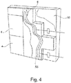
- Fig. 1 is a detail of a facade of a building with a building-integrated photovoltaic module 2 is shown.
- the photovoltaic module 2 here comprises a plurality of individual photovoltaic elements 4 and regularly represents a photovoltaic composite layer system. Usually, several such photovoltaic elements 4 are preferably arranged directly adjacent to one another and are electrically connected to one another in a manner not shown here.
- the photovoltaic module 2 is a flexible, film-like system containing photovoltaic elements 4, in particular in the form of OPV units. Such film-like photovoltaic modules 2 have a very high degree of flexibility.
- OPV elements in particular are characterized by an extremely thin design. The average thickness is regularly in the range of 0.1 mm to 5 mm.
- the photovoltaic modules 2 have a large number of individual photovoltaic cells. These are suitably connected within the photovoltaic element 4 by electrical conductor tracks. A connecting line is also assigned to each individual photovoltaic element 4, with a plurality of photovoltaic elements 4 being connected to one another in a suitable manner via the connecting lines. These connecting lines come after installation in a manner not shown in contact with z.
- the individual photovoltaic modules 2 are suitably fitted over their entire surface into an outer skin 6 of the facade, e.g. in a plaster coating, e.g. the facade coating, or a facade panel, in particular a carrier panel or a thermal insulation panel, integrated. They can also rest on such an outer skin. Additional supporting structures attached to the outer skin 6, such as profiles or other fastening elements, can be completely dispensed with here. Rather, the individual photovoltaic modules 2 are connected directly to the outer skin 6 via the connection and compensation layer. In the embodiment shown, the entire surface of the photovoltaic modules 2 is in contact with an adhesive and installation layer in the form of a plaster 8A, 8B of the outer skin 6.
- the outer skin 6 is in the embodiments of the Figures 1 and 4th applied to an outer wall 10, for example a brick wall.
- the outer skin 6 in the exemplary embodiment is a plaster 8A applied to the outer wall 10, which here forms the adhesive and installation layer.
- the photovoltaic modules 2 are attached to the entire surface of this.
- the outer skin 6 also includes a top plaster 12 in some areas, which is applied to the plaster 8A in free areas that are not covered by the photovoltaic modules 2.
- the individual photovoltaic modules 2 are arranged in groups that are spaced apart.
- the top coat 12 is applied in the intermediate area between the two groups.
- connection and compensation layer 14 can preferably be pressed into a still moist plaster 8A, so that this plaster 8A as an adhesive and installation layer forms a firm connection with the connection and compensation layer 14 during drying and curing.
- a transparent protective layer 16 in the form of a plate is also assigned to a respective photovoltaic module 2 in the illustrated embodiment.
- This protective layer seals the photovoltaic module 2 from the surroundings.
- This plate 16 is for example a glass or plastic plate with high inherent rigidity. This is, for example, applied to the actually film-like photovoltaic module 2, in particular glued on.
- the photovoltaic assembly 2 prepared in this way with the plate 16 has an inherent rigidity.
- Fig. 3 shows the structure of an expedient embodiment of a photovoltaic module 2.
- the connection and compensation layer 14 in the form of a fleece layer is followed by the second coupling layer 20 in the form of an adhesive layer.
- the connection to the composite photovoltaic system, also called photovoltaic element 4 then takes place via the first coupling layer 17.
- this photovoltaic composite layer system comprises, as an OPV system, a substrate layer, a charge conductor layer, a semiconductor layer and a gas barrier layer (not shown).
- the protective layer 16 in the form of a rigid transparent plate adjoins the photovoltaic composite layer system 4.
- connection and compensation layer 14 compensates for the different thermal expansion behavior of adjacent layers such as flush-mounted on the one hand and photovoltaic module 2, reflector layer and / or gas barrier layer on the other. Due to the connection and compensation layer 14, temperature-induced shear or shear stresses are either not transmitted at all or significantly reduced between the flush-mounted and the photovoltaic element 4.
- This connection and compensation layer 14 is, as in Fig. 3 indicated, connected to or embedded in the adhesive and installation layer present in the form of a plaster 8A.
- the flush-mounted works here as an adhesive and installation layer.
- the photovoltaic element 4 is on the connection and compensation layer 14 Figure 3 applying an adhesive layer 20 as the first coupling layer with the integration of gas barrier and reflector layer applied over the entire surface.
- the adhesive layer can also be formed by punctual adhesive points.
- the structure of an expedient photovoltaic module 2 shown is preferably designed as a prefabricated module and thus as a prefabricated photovoltaic module 2. As such, this can be delivered to the construction site and made available there.
- the assembly 2 only needs to be attached to the outer skin 6 as such to be, especially by pressing against the wet flush 9 as an adhesive and installation layer.
- the photovoltaic element 4 and the connection and compensation layer 14 have the same base area and therefore overlap one another.
- this also applies in addition to this protective layer 16.
- the connection and compensation layer 14 in which the connection and compensation layer 14 is first installed on site before the photovoltaic elements 4 can be applied the connection and compensation layer 14 also have a different base area than the photovoltaic elements.
- connection of the photovoltaic elements 4 or, if applicable, the gas barrier and rear side barrier to the connection and compensation layer 14 and / or also the connection of the connection and compensation layer 14 to the flush-mounted 8A, i.e. to the adhesive and installation layer is detachable, so that either the photovoltaic elements 4 as such or together with the connection and compensation layer 14 or with parts thereof are removed without significant destruction of the level below and replaced by new photovoltaic elements 4 can.
Description
Die vorliegende Erfindung betrifft einen Baukörper, umfassend eine Photovoltaik-Baueinheit, einen Wandaufbau mit einer Fassadenseite, umfassend fassadenseitig mindestens einen erfindungsgemäßen Baukörper sowie die Verwendung des erfindungsgemäßen Baukörpers für die Verkleidung von Gebäudefassaden.The present invention relates to a structure comprising a photovoltaic module, a wall structure with a facade side, comprising at least one structure according to the invention on the facade side, and the use of the structure according to the invention for cladding building facades.
Photovoltaikanlagen zur Gewinnung elektrischer Energie werden seit langem auf Dächern angebracht. Diesem Umstand liegt die Erkenntnis zu Grunde, dass bei möglichst senkrechtem Einfall der Sonnenstrahlen auf die Solarzelle die Energieausbeute ihr Maximum erreicht. Auf Grund der Weiterentwicklung der Solarzellentechnik lassen sich mittlerweile Solarzellen mit einem sehr hohen Wirkungsgrad auch in der Massenfertigung herstellen, mit denen sich Anwendungsmöglichkeiten erschließen, welche mit Solarzellen älterer Bauart nicht attraktiv genug erschienen. So wird beispielsweise seit einiger Zeit auch die Einbindung der Solartechnik in Gebäudefassaden versucht.Photovoltaic systems for the generation of electrical energy have long been installed on roofs. This fact is based on the knowledge that when the sun's rays hit the solar cell as vertically as possible, the energy yield reaches its maximum. Due to the further development of solar cell technology, solar cells with a very high degree of efficiency can now also be mass-produced, which open up application possibilities that did not appear attractive enough with older-type solar cells. For example, the integration of solar technology in building facades has been attempted for some time.
Exemplarisch sei auf die
Die
Die
Die
Die
Die
Die
Die
Aus der
Zur Anbringung einer gebäudeintegrierten Photovoltaik stellt die
Die
Die aus dem Stand der Technik bekannten gebäudeintegrierten Photovoltaiksysteme sind in der Herstellung und/oder in der Anbringung noch stets relativ aufwendig. Es wäre daher wünschenswert, auf gebäudeintegrierte Photovoltaikeinrichtungen zurückgreifen zu können, die nicht mit den Nachteilen des Stands der Technik behaftet sind. Demgemäß lag der vorliegenden Erfindung die Aufgabe zu Grunde, eine gebäudeintegrierbare Photovoltaik-Baueinheit verfügbar zu machen, die eine leichte und zuverlässige Anbringung einer Gebäudefassade gestattet und die gleichzeitig gute Dauergebrauchseigenschaften und hohe Wirkungsgrade auch nach mehrjähriger Nutzung zulässt und die darüber hinaus ohne großen Aufwand ersetzt werden kann.The building-integrated photovoltaic systems known from the prior art are still relatively complex to manufacture and / or to install. It would therefore be desirable to be able to use building-integrated photovoltaic devices which do not have the disadvantages of the prior art. Accordingly, the present invention was based on the object of a building-integrated photovoltaic module to make available, which allows an easy and reliable attachment of a building facade and at the same time allows good long-term properties and high efficiencies even after several years of use and which can also be replaced without much effort.
Demgemäß wurde ein Baukörper gemäß den Merkmalen des Patentanspruchs 1 gefunden.Accordingly, a structure according to the features of claim 1 was found.
Hierbei ist die Anbindungs- und Kompensationsschicht eingerichtet und ausgelegt, um Dehnungen oder Formveränderungen mindestens einer zur ersten Seite benachbarten Schicht und/oder, vorzugsweise und, um Dehnungen oder Formveränderungen einer über die zweite Seite verbundenen bzw. verbindbaren Schicht sowie um relative Lageveränderungen von mindestens einer zur ersten Seite benachbarten Schicht und der über die zweite Seite verbundenen bzw. verbindbaren Schicht zu kompensieren. Die Anbindungs- und Kompensationsschicht ist demgemäß insbesondere auch eingerichtet und ausgelegt, um die relative Lageveränderung von mindestens einer zur ersten Seite benachbarten Schicht und der über die zweite Seite verbundenen bzw. verbindbaren Schicht zu kompensieren. Mit der Anbindungs- und Kompensationsschicht c) sollen bevorzugt mechanische Spannungen in und zwischen Schichten bzw. Lagen, die benachbart zu dieser Schicht c) vorliegen, ausgeglichen werden. Auf diese Weise kann eine Beeinträchtigung des Photovoltaikverbundlagensystems, beispielsweise ein Einreißen oder Dehnen bzw. Überdehnen dieses Photovoltaikverbundlagensystems, vermieden oder jedenfalls signifikant zurückgedrängt werden.Here, the connection and compensation layer is set up and designed to accommodate strains or changes in shape of at least one layer adjacent to the first side and / or, and preferably, stretches or changes in shape of a layer connected or connectable via the second side and relative changes in position of at least one to compensate for the layer adjacent to the first side and the layer connected or connectable via the second side. The connection and compensation layer is accordingly in particular also set up and designed to compensate for the relative change in position of at least one layer adjacent to the first side and the layer connected or connectable via the second side. The connection and compensation layer c) should preferably be used to compensate for mechanical stresses in and between layers or layers which are adjacent to this layer c). In this way, impairment of the composite photovoltaic system, for example tearing or stretching or overstretching of this composite photovoltaic system, can be avoided or at least significantly suppressed.
Eine gebäudeintegrierbare Photovoltaik-Baueinheit soll nicht nur ein Bauteil darstellen, das ein anderes Bauteil einer Gebäudehülle bzw. -fassade ersetzt, wie dieses gemäß dem deutschen Normenentwurf DIN VDE 0126-21 vorgesehen ist, sondern Photovoltaikverbundlagensysteme, umfassend mindestens ein Dünnschicht-Photovoltaikelement, die an einer Fassade anbringbar oder in eine solche Fassade integrierbar sind.A building-integrable photovoltaic unit should not only represent a component that replaces another component of a building envelope or facade, as is provided in accordance with the German draft standard DIN VDE 0126-21, but also composite photovoltaic systems, comprising at least one thin-film photovoltaic element can be attached to a facade or integrated into such a facade.
Hierbei kann das Photovoltaikverbundlagensystem in einer besonders zweckmäßigen Ausgestaltung mindestens ein organisches Photovoltaikelement (OPV) oder ein anorganisches Dünnschicht-Photovoltaikelement umfassen. Hierbei können grundsätzlich alle Dünnschicht-Photovoltaikmodule, die in einer Fassadekonstruktion mit der Photovoltaik-Baueinheit verbaut werden können, zum Einsatz kommen. Besonders geeignet sind neben den Dünnschichtmodulen, z.B. auf CdTe-, CIGS-, CIS- und a-Si-Basis sowie auf Basis artverwandter Technologien, auch organische Solarzellen, Farbstoffsolarzellen (DSSC) und Solarzellen auf Basis von Perowskit.In a particularly expedient embodiment, the composite photovoltaic system can comprise at least one organic photovoltaic element (OPV) or one inorganic thin-film photovoltaic element. In principle, all thin-film photovoltaic modules that can be installed in a facade construction with the photovoltaic module can be used. In addition to the thin-film modules, e.g. based on CdTe, CIGS, CIS and a-Si as well as on the basis of related technologies, also organic solar cells, dye solar cells (DSSC) and solar cells based on perovskite.
Das Photovoltaikverbundlagensystem kann außerdem auf einem photovoltaischen Modul basieren, umfassend eine Vielzahl an Photovoltaik-Zellen, die zwischen einer im Wesentlichen lichtdurchlässigen ersten elektrischen Anschlussschicht und einer im Wesentlichen lichtdurchlässigen zweiten elektrischen Anschlussschicht angeordnet sind, wobei mindestens zwei der Vielzahl an photovoltaischen Zellen eine photosensibilisierte Nanomatrix-Schicht und ein Ladungsträgermedien umfassen. Die photosensibilisierte Nanomatrix-Schicht weist vorzugsweise Partikel mit einer durchschnittlichen Größe im Bereich von etwa 5 nm bis etwa 300 nm, vorzugsweise im Bereich von etwa 10 nm bis etwa 40 nm auf. Bei diesen Partikeln handelt es sich vorzugsweise um Titandioxid-Nanopartikel. Außerdem können diese Partikel ausgewählt werden aus der Gruppe bestehend aus Zirkoniumoxid, Zinkoxiden, Wolframoxiden, Sulfiden, Seleniden, Telluriden und einer beliebigen Kombinationen davon. Die photosensibilisierten Nanopartikel liegen in der Nanomatrix-Schicht vorzugsweise miteinander verbunden vor. Das Ladungsträgermedium umfasst in einer zweckmäßigen Ausgestaltung ein Elektrolyt- Redoxsystem, wobei bevorzugt ein Polymerelektrolyt zum Einsatz kommt. Besonders bevorzugt wird bei der hier dargestellten Ausführungsform eines photovoltaischen Moduls auf erste und zweite photovoltaische Zellen zurückgegriffen, die jeweils über die geschilderte photosensibilisierte Nanomatrix-Schicht und das Ladungsträgermedium verfügen. Diese ersten und zweiten photovoltaischen Zellen liegen vorzugsweise zwischen einer ersten flexiblen lichtdurchlässigen Substratschicht und einer zweiten flexiblen lichtdurchlässigen Substratschicht vor. Hierbei liegt auf der ersten flexiblen lichtdurchlässigen Substratschicht mindestens ein Isolator auf, der mindestens einen Abschnitt der ersten photovoltaischen Zelle von der zweiten photovoltaischen Zelle isoliert. Die zweite flexible lichtdurchlässige Substratschicht verfügt dabei vorzugsweise über erste und zweite leitfähige Elemente, die auf dieser aufliegen, wobei das erste leitfähige Element mit der ersten photovoltaischen Zelle zur Durchleitung des Stroms in einer ersten Richtung verbunden ist und wobei das zweite leitfähige Element mit der zweiten photovoltaischen Zelle verbunden ist und den Strom in eine zweite Richtung leitet, die der ersten Richtung entgegengesetzt ist. ITO stellt beispielsweise ein geeignetes Material für das erste leitfähige Element dar. Ferner kommen im Zusammenhang mit der vorangehend geschilderten Ausführungsform auch solche photovoltaischen Module in Betracht, die mindestens zwei photovoltaische Zellen umfassen, die zwischen einer im Wesentlichen lichtdurchlässigen ersten elektrischen Anschlussschicht und einer im Wesentlichen lichtdurchlässigen zweiten elektrischen Anschlussschicht vorliegen, wobei eine der mindestens zwei photovoltaischen Zellen eine wie vorangehend geschilderte photosensibilisierte Nanomatrix-Schicht aufweist, die zwischen einer ersten elektrischen Verbindungsschicht und einem Ladungsträgermedium angeordnet ist, und wobei die andere der mindestens zwei photovoltaischen Zellen eine wie vorangehend geschilderte photosensibilisierte Nanomatrix-Schicht aufweist, die zwischen der zweiten elektrischen Anschlussschicht und einem Ladungsträgermedien angeordnet ist. Geeignete photovoltaische Module, wie vorangehend ausgeführt, finden sich auch in der
Im Sinne dieser Erfindung soll unter einem gebäudeintegrierbaren organischen Photovoltaikelement auch ein solches verstanden werden, bei dem das Photovoltaikelement auf einer Außenlage eines Gebäudes auf- bzw. angebracht werden kann.For the purposes of this invention, a building-integrable organic photovoltaic element should also be understood to mean one in which the photovoltaic element can be attached or attached to an outer layer of a building.
Die Photovoltaikverbundlagen sind in einer bevorzugten Ausgestaltung biegeflexibel, das heißt sie sind bieg- bzw. krümmbar und können demgemäß als dünne, bieg- bzw. krümmbare Flächengebilde, beispielsweise in Folienform, vorliegen. In einer zweckmäßigen Ausgestaltung können geeignete Photovoltaikverbundlagen auf einer Rolle aufgerollt vorliegen. Eine besonders zweckmäßige Ausgestaltung der Photovoltaik-Baueinheit sieht vor, dass die erste Kopplungslage und die Anbindungs- und Kompensationsschicht ein laminiertes Lagensystem bilden. Diese Einheiten können somit als baulicher Verbund eingesetzt werden, wodurch die Herstellung der Photovoltaik-Baueinheiten nochmals erleichtert wird. In einer bevorzugten Ausgestaltung der Photovoltaik-Baueinheit ist vorgesehen, dass das OPV-System in Richtung von der ersten Kopplungslage zur Schutzschicht bzw. zur Einstrahlseite des Sonnenlichts umfasst: mindestens eine Substratschicht, mindestens eine Ladungsleiterlage, mindestens eine Halbleiterlage und mindestens eine Rückseitenbarrierelage. Von Vorteil bei den organischen Photovoltaik-Baueinheiten ist auch, dass diese in beliebiger Größe und Form vorgefertigt werden können. Dieses gestattet eine flexible Anbringung an Gebäudefassaden. Es ist sogar möglich, die Photovoltaik-Baueinheiten erst an der Baustelle in die geforderte Form zu bringen.In a preferred embodiment, the photovoltaic composite layers are flexible in terms of bending, that is to say they are bendable or bendable and can accordingly be present as thin, bendable or bendable flat structures, for example in the form of a film. In an expedient embodiment, suitable photovoltaic composite layers can be rolled up on a roll. A particularly expedient embodiment of the photovoltaic module provides that the first coupling layer and the connection and compensation layer form a laminated layer system. These units can therefore be considered structural Composite can be used, which makes the manufacture of photovoltaic modules even easier. In a preferred embodiment of the photovoltaic assembly, it is provided that the OPV system in the direction from the first coupling layer to the protective layer or to the irradiation side of sunlight comprises: at least one substrate layer, at least one charge conductor layer, at least one semiconductor layer and at least one rear barrier layer. Another advantage of organic photovoltaic modules is that they can be prefabricated in any size and shape. This allows flexible attachment to building facades. It is even possible to bring the photovoltaic modules into the required form only at the construction site.
In einer zweckmäßigen Ausgestaltung enthält die organische Photovoltaik-Baueinheit ferner
- e) eine Rückseitenbarriere und/oder eine erste Gasbarrierelage zwischen erster Kopplungslage und der Anbindungs- und Kompensationsschicht und
- f) eine zweite Kopplungslage zur Verbindung der Rückseitenbarriere mit der Anbindungs- und Kompensationsschicht.
- e) a backside barrier and / or a first gas barrier layer between the first coupling layer and the connection and compensation layer and
- f) a second coupling layer for connecting the rear barrier to the connection and compensation layer.
Die Gasbarriererelage ist bevorzugt eine Sauerstoffbarrierelage, d.h. sie ist ausgelegt und eingerichtet, um den Durchtritt von gasförmigem Sauerstoff zu verhindern. In einer besonders zweckmäßigen Ausgestaltung verhindert die Gasbarrierelage den Durchtritt von Wasserdampf und von gasförmigem Wasser, bevorzugt zusätzlich zu ihrer Funktion als Sauerstoffbarrierelage. Die Gasbarrierelage ist besonders bevorzugt undurchlässig für jegliche gasförmigen Bestandteile. Die Reflektorschicht ist bevorzugt in Form einer Gasbarriererelage ausgebildet, und liegt damit in dieser Ausgestaltung vorzugsweise einstückig als Reflektor- und Gasbarriereschicht vor. Hierfür kommen zum Beispiel mit anorganischen Materialien beschichtete Kunststofffolien oder, z.B. aufkaschierte, dünne Metallfolien in Betracht. In einer besonders geeigneten Ausführungsvariante der Photovoltaik-Baueinheit stellt die Anbindungs- und Kompensationsschicht mindestens eine Vlies-, Gewebe- oder Gewirklage, insbesondere mindestens eine Vliesschicht und/oder mindestens eine Gittergewebeschicht, dar oder enthält diese. Darüber hinaus können als Anbindungs- und Kompensationsschicht auch Gummilagen, die mit einer Klebe- oder Laminierschicht versehen sind, zum Einsatz kommen. Besonders bevorzugt werden Vlieslagen als Anbindungs- und Kompensationsschichten eingesetzt. Darüber hinaus können in einer weiteren zweckmäßigen Ausführungsform auch Anbindungs- und Kompensationsschichten in Form von Gewebe- oder Gewirklagen eingesetzt werden. Dabei kann in einer besonders zweckmäßigen Ausgestaltung vorgesehen sein, dass die Vlieslage Naturfasern, chemische Cellulosefasern, Glasfasern und/oder Polymerfasern, insbesondere Polyesterfasern, und/oder polymerbeschichtete, insbesondere polyesterbeschichtete, Glasfasern umfasst oder hieraus besteht. Auch kann die Gewebelage ein Klettverschlussband, insbesondere ein Hakenklettverschlussband, umfassen. Die Anbindungs- und Kompensationsschicht kann nicht nur einlagig, sondern ebenfalls zwei- oder mehrlagig ausgebildet sein, beispielsweise ein Verbundsystem aus mehreren Lagen bilden, welche vorzugsweise elastisch miteinander verbunden sind.The gas barrier layer is preferably an oxygen barrier layer, ie it is designed and set up to prevent the passage of gaseous oxygen. In a particularly expedient embodiment, the gas barrier layer prevents the passage of water vapor and gaseous water, preferably in addition to their function as an oxygen barrier layer. The gas barrier layer is particularly preferably impermeable to any gaseous components. The reflector layer is preferably designed in the form of a gas barrier layer, and is therefore preferably in one piece in this embodiment as a reflector and gas barrier layer. For this purpose, for example, plastic films coated with inorganic materials or, for example, laminated-on, thin metal films come into consideration. In a particularly suitable embodiment variant of the photovoltaic module, the connection and compensation layer represents or contains at least one fleece, fabric or knitted layer, in particular at least one fleece layer and / or at least one grid fabric layer. In addition, rubber layers provided with an adhesive or laminating layer can also be used as the connection and compensation layer. Nonwoven layers are particularly preferably used as connection and compensation layers. In addition, another Expedient embodiment, connection and compensation layers in the form of woven or knitted layers are also used. In a particularly expedient embodiment, it can be provided that the nonwoven layer comprises or consists of natural fibers, chemical cellulose fibers, glass fibers and / or polymer fibers, in particular polyester fibers, and / or polymer-coated, in particular polyester-coated, glass fibers. The fabric layer can also include a Velcro fastener tape, in particular a hook-and-loop fastener tape. The connection and compensation layer can be designed not only in one layer, but also in two or more layers, for example forming a composite system from several layers, which are preferably elastically connected to one another.
Bei solchen mehrlagigen Systemen können die Anbindungs- und Kompensationseigenschaften auf mehrere Lagen verteilt sein. Beispielsweise kann die äußere Lage für die Anbindung an eine Träger- oder Dämmplatte oder eine anderweitige Fassadenplatte ausgelegt und eingerichtet sein, während eine weitere Lage die Kompensationseigenschaften zur Verfügung stellt. Das mehrlagige System ist derart gestaltet, dass die für die Anbindung vorgesehene Lage die Kompensationseigenschaften der weiteren Schicht(en) nicht be- oder verhindert. In einer besonders zweckmäßigen Ausgestaltung können die sich gegenüberliegenden Außenlagen einer mehrlagigen Anbindungs- und Kompensationsschicht aus einer Vlies-, Gewebe- oder Gewirklage, insbesondere Vlieslage, gebildet sein. Zwischen diesen Vlieslagen kann z.B. eine Kleberschicht oder eine elastische Lage, beispielsweise auf Gummibasis, vorliegen.In such multilayer systems, the connection and compensation properties can be distributed over several layers. For example, the outer layer can be designed and set up for the connection to a support or insulation panel or another facade panel, while a further layer provides the compensation properties. The multilayer system is designed in such a way that the layer provided for the connection does not hinder or prevent the compensation properties of the further layer (s). In a particularly expedient embodiment, the opposite outer layers of a multilayer connection and compensation layer can be formed from a non-woven, woven or knitted layer, in particular a non-woven layer. Between these fleece layers e.g. there is an adhesive layer or an elastic layer, for example based on rubber.
Ferner ist in einer besonders bevorzugten Ausführungsform vorgesehen, dass die erste und/oder zweite Kopplungslage eine Klebeschicht oder eine Laminierlage darstellen oder umfassen.Furthermore, it is provided in a particularly preferred embodiment that the first and / or second coupling layer represent or comprise an adhesive layer or a laminating layer.
Bei der Schutzschicht kann es sich zum Beispiel um eine Platte aus Glas oder einem transparenten Kunststoff handeln. Als Schutzschicht kann auch eine kratzfeste Beschichtung gemäß
Die Schutzschicht schützt die Photovoltaikverbundlage vor mechanischer Beschädigung. Die Schutzschicht kann zum Beispiel unmittelbar an der Photovoltaikverbundlage anliegen, kann aber auch mittels einer Kleberschicht, z.B. einer 2K-Kleberschicht, mit dieser verbunden sein. Gemäß einer weiteren Ausführungsvariante ist es möglich, die Schutzschicht in Form einer Kunststoff- oder Glasplatte beabstandet von der Photovoltaikverbundlage zu positionieren, beispielsweise mittels geeigneter Befestigungs- und/ oder Trägerelemente.The protective layer protects the photovoltaic composite layer from mechanical damage. The protective layer can, for example, lie directly on the photovoltaic composite layer, but can also be by means of an adhesive layer, e.g. a 2K adhesive layer. According to a further embodiment variant, it is possible to position the protective layer in the form of a plastic or glass plate at a distance from the photovoltaic composite layer, for example by means of suitable fastening and / or support elements.
Außerdem hat es sich als sehr vorteilhaft erwiesen, die Photovoltaikverbundlage vollständig bzw. vollflächig über die erste Kopplungslage mit der Anbindungs- und Kompensationslage zu verbinden. Eine vollflächige Verbindung im Sinne der vorliegenden Erfindung gelingt auch über eine sogenannte Kratzspachtelung. Über die vollflächige Anbindung wird besonders vorteilhaft eine Fixierung der Photovoltaikverbundlage, insbesondere auch des OPV-Systems, erreicht, die keine Wellenbildung zeigt bzw. nicht zur Wellenbildung neigt.In addition, it has proven to be very advantageous to connect the photovoltaic composite layer completely or over the entire area to the connection and compensation layer via the first coupling layer. A full-area connection in the sense of the present invention can also be achieved by means of a so-called scratch filler. The full-surface connection is particularly advantageously a fixation of the photovoltaic composite layer, in particular also of the OPV system, which shows no wave formation or does not tend to wave formation.
In der letztgenannten Ausführungsform eines erfindungsgemäßen Baukörpers kann vorgesehen sein, dass zwischen der Haft- und Installationsschicht und dem Photovoltaikverbundlagensystem eine Rückseitenbarrierenlage und/oder eine Gasbarrierelage, insbesondere Sauerstoffbarrierelage, vorliegt, über die die Anbindung des Photovoltaikverbundlagensystems an die Fassadenplatte vermittels der Haft- und Installationsschicht erfolgt. Hierbei können Reflektorschicht und Gasbarrierelage bzw. Sauerstoffbarrierelage auch einstückig ausgebildet sein. Alternativ kann die Gasbarrierelage, insbesondere Sauerstoffbarrierelage, in Bezug auf das Photovoltaikverbundlagensystem hinter oder vor, vorzugsweise hinter der Rückseitenbarriere vorliegen. Beispielsweise kann die Gasbarrierelage, insbesondere Sauerstoffbarrierelage, in Form einer Kunststofffolie ausgebildet sein, die insbesondere als Laminatfolie zur Befestigung an die Rückseitenbarriere oder das Photovoltaikverbundlagensystem herangezogen werden kann.In the last-mentioned embodiment of a structure according to the invention it can be provided that between the adhesive and installation layer and the photovoltaic composite layer system there is a rear barrier layer and / or a gas barrier layer, in particular an oxygen barrier layer, via which the photovoltaic composite layer system is connected to the facade panel by means of the adhesive and installation layer . Here, the reflector layer and gas barrier layer or oxygen barrier layer can also be formed in one piece. Alternatively, the gas barrier layer, in particular oxygen barrier layer, can be present behind or in front of, preferably behind the rear barrier in relation to the photovoltaic composite layer system. For example, the gas barrier layer, in particular oxygen barrier layer, can be designed in the form of a plastic film, which can be used in particular as a laminate film for attachment to the rear side barrier or the photovoltaic composite layer system.
Bei den erfindungsgemäßen Baukörpern kann die Fassadenplatte eine Trägerplatte, insbesondere eine Putzträgerplatte, oder eine Dämmplatte, insbesondere eine geschäumte Dämmplatte, eine Mineralwoll-Dämmplatte, eine Dämmplatte auf Basis von Naturfasern und/oder eine Calciumsilikat-Dämmplatte, umfassen oder hieraus bestehen. In einer Ausführungsform kann die Fassadenplatte eine wärmedämmende oder wärmegedämmte Trägerplatte darstellen. Bei dieser Ausgestaltung bildet die Fassadenplatte eine kombinierte Dämm- und Trägerplatte. Bei der Fassadenbeschichtung der erfindungsgemäßen Baukörper handelt es sich regelmäßig um eine Putzbeschichtung erhalten aus einer mineralischen Beschichtungsmasse. In dieser Fassaden- bzw. Putzbeschichtung kann auch ein Armierungsgewebe vorliegen.In the structures according to the invention, the facade panel can comprise or consist of a carrier panel, in particular a plaster carrier panel, or an insulating panel, in particular a foamed insulating panel, a mineral wool insulating panel, an insulating panel based on natural fibers and / or a calcium silicate insulating panel. In one embodiment, the facade panel can be a heat-insulating or heat-insulated support panel. In this embodiment, the facade panel forms a combined insulation and carrier panel. The facade coating of the structures according to the invention is regularly a plaster coating obtained from a mineral coating material. A reinforcing fabric can also be present in this facade or plaster coating.
Als besonders interessant hat sich erwiesen, dass auch Wärmedämmverbundsysteme mit den Photovoltaik-Baueinheiten ausgestattet werden können. Dabei können diese Wärmedämmverbundsysteme bereits als Modul vorliegen, auf denen fassadenseitig die Photovoltaik-Baueinheit vorliegt, oder das Wärmedämmverbundsystem wird zunächst an einer Gebäudefassade angebracht und anschließend mit der Photovoltaik-Baueinheit versehen mittels der Haft- und Installationsschicht.It has proven to be particularly interesting that thermal insulation composite systems can also be equipped with the photovoltaic modules. These thermal insulation composite systems can already exist as a module on which the photovoltaic assembly is on the facade side, or the thermal insulation composite system is first attached to a building facade and then provided with the photovoltaic assembly by means of the adhesive and installation layer.
Die Haft- und Installationsschicht ist im Sinne der Erfindung eine Installationsschicht, als dass durch diese mindestens eine, insbesondere eine Vielzahl an Verbindungsleitungen zu dem Photovoltaik-verbundlagensystem oder der Photovoltaik-Baueinheit hindurchgehen und/oder zumindest abschnittsweise verlaufen können. Die Träger- bzw. Wärmedämmplatte kann hierbei in bekannter Weise, beispielsweise mittels Klebens und/oder Dübelns, an einer Gebäudefassade befestigt werden.In the sense of the invention, the adhesive and installation layer is an installation layer such that at least one, in particular a plurality, of connecting lines to the photovoltaic composite layer system or the photovoltaic structural unit can pass through it and / or can run at least in sections. The carrier or thermal insulation board can be attached to a building facade in a known manner, for example by means of gluing and / or doweling.
Selbstverständlich ist es ebenfalls möglich, auf der Fassadenplatte, insbesondere der Trägerplatte oder der Wärmedämmplatte, einen Putz, beispielsweise einen Unterputz aufzutragen. Diese Putzschichtung kann dann vorzugsweise auch mit einem Armierungsgewebe versehen sein. Beispielsweise kann das Armierungsgewebe darin eingebettet vorliegen.Of course, it is also possible to apply a plaster, for example a plaster, to the facade panel, in particular the carrier panel or the thermal insulation panel. This plaster layer can then preferably also be provided with a reinforcing fabric. For example, the reinforcement fabric can be embedded therein.
Der erfindungsgemäße Baukörper ermöglicht es, möglichst viele Komponenten wie beispielsweise elektrische Leitungen und Anschlüsse im Vorfeld mit zu verbauen. Erfindungsgemäß sind Versorgungsleitungen in entsprechend konstruierte Nuten von Fassadenbeschichtung oder Fassadenplatte, insbesondere von Trägerplatte oder Wärmedämmplatte, und/oder Haft- und Installationsschicht verlegt. Dadurch gelingt eine zügige und einfache Montage an der Baustelle.The structure according to the invention makes it possible to install as many components as possible, for example electrical lines and connections, in advance. According to the invention, supply lines are laid in appropriately designed grooves in the facade coating or facade panel, in particular in the carrier panel or thermal insulation panel, and / or the adhesive and installation layer. This enables quick and easy assembly at the construction site.
Die Haft- und Installationsschicht des erfindungsgemäßen Baukörpers umfasst eine mineralische Bindemittelmasse, insbesondere einen Putzmörtel, oder ist hieraus gebildet. Die Haft- und Installationsschicht verbindet die Anbindungs- und Kompensationsschicht der Photovoltaik-Baueinheit mit der Fassadenbeschichtung oder der Fassadenplatte, insbesondere der Trägerplatte oder der Wärmedämmplatte, und erlaubt gleichzeitig, die Einbindung bzw. Verlegung oder Leitung von elektrischen Verbindungen und elektrischen Baukörpern, um die mit dem Photovoltaikverbundlagensystem erzeugte elektrische Energie abzuführen.The adhesive and installation layer of the structure according to the invention comprises or is formed from a mineral binder composition, in particular a plastering mortar. The adhesive and installation layer connects the connection and compensation layer of the photovoltaic module with the facade coating or the facade panel, in particular the carrier panel or the thermal insulation panel, and at the same time allows the integration or laying or routing of electrical connections and electrical structures to which the to dissipate electrical energy generated in the composite photovoltaic system.
Darüber hinaus greift man vorteilhafterweise auf solche erfindungsgemäßen Baukörper und Photovoltaik-Baueinheiten zurück, bei denen die Anbindungs- und Kompensationsschicht der Photovoltaik-Baueinheit eine Vlieslage umfasst, insbesondere gebildet aus Glasfasern, Polymerfasern und/oder polymerbeschichteten, insbesondere polyesterbeschichteten, Glasfasern. Die Anbindungs- und Kompensationsschicht aus faserenthaltendem Material, insbesondere in Form eines Vlieses, auszuführen, hat sich als besonders vorteilhaft erwiesen. Zum einen gelingt auf diese Weise die unmittelbare Anbindung bzw. Einbettung in eine Haft- und Installationsschicht, z.B. auf Basis eines mineralischen Bindemittels, wie dieses bei der Fassadengestaltung üblicherweise zum Einsatz kommt. Durch das Einbetten wird eine Verzahnung der Faserstruktur von Vlies-, Gewebe- oder Gewirklage mit der Masse der Haft- und Installationsschicht, beispielsweise einer mineralischen Putzmasse, erreicht. Es ist folglich möglich, auf aufwendige Trägerkonstruktionen zu verzichten. Vielmehr gelingt mit den erfindungsgemäßen Baukörpern die unmittelbare Integration in bzw. Anbindung an übliche Fassadengestaltungen. Hierdurch wird eine sehr große gestalterische wie auch bautechnische Freiheit ermöglicht. Darüber hinaus geht mit der Verwendung der genannten Anbindungs- und Kompensationsschichten der Photovoltaik-Baueinheiten bzw. der erfindungsgemäßen Baukörper der überraschende Vorteil einher, dass mechanische Spannungen, die sich, beispielsweise auf Grund unterschiedlichen thermischen Ausdehnungsverhaltens benachbarter Materialien, zwischen den mit der Anbindungs- und Kompensationsschicht verbundenen Lagen bzw. Schichten einstellen können, ausgeglichen werden. Folglich kann eine Zerstörung oder Beeinträchtigung des Photovoltaik-Elements der Photovoltaik-Baueinheit bzw. der erfindungsgemäßen Baukörper vermieden werden. Auch gelingt es mit der Anbindungs- und Kompensationsschicht, Dimensionsänderungen, die sich nur auf einer Seite einstellen, beispielsweise Rissbildung, auszugleichen. Somit kann eine fassadenseitig eingetretene Rissbildung, beispielsweise in einem Unterputz oder in einer Trägerplatte, durch die Anbindungs- und Kompensationsschicht aufgefangen und ausgeglichen werden, wodurch eine Beeinträchtigung der Photovoltaikverbundlage vermieden und die Lebensdauer von Photovoltaik-Baueinheit und erfindungsgemäßem Baukörper verlängert wird.In addition, use is advantageously made of such structures and photovoltaic modules according to the invention in which the connection and Compensation layer of the photovoltaic module comprises a nonwoven layer, in particular formed from glass fibers, polymer fibers and / or polymer-coated, in particular polyester-coated, glass fibers. Executing the connection and compensation layer from fiber-containing material, in particular in the form of a fleece, has proven to be particularly advantageous. On the one hand, this enables the direct connection or embedding in an adhesive and installation layer, for example based on a mineral binder, as is usually used in facade design. By embedding, the fiber structure of the nonwoven, woven or knitted layer is interlocked with the mass of the adhesive and installation layer, for example a mineral plastering compound. It is therefore possible to dispense with elaborate support structures. Rather, the structures according to the invention enable direct integration into or connection to conventional facade designs. This enables a very large freedom of design and construction. In addition, the use of the mentioned connection and compensation layers of the photovoltaic modules or of the structures according to the invention is accompanied by the surprising advantage that mechanical stresses, for example due to different thermal expansion behavior of adjacent materials, between those with the connection and compensation layer connected layers or layers can be compensated. As a result, destruction or impairment of the photovoltaic element of the photovoltaic assembly or of the structure according to the invention can be avoided. With the connection and compensation layer, it is also possible to compensate for dimensional changes that only occur on one side, for example cracking. A crack formation that has occurred on the facade, for example in a flush-mounted or in a carrier plate, can thus be absorbed and compensated for by the connection and compensation layer, thereby avoiding impairment of the photovoltaic composite layer and extending the lifespan of the photovoltaic assembly and the inventive structure.
Grundsätzlich ist es ebenfalls möglich, die Anbindungs- und Kompensationsschicht zunächst mittels der Haft- und Installationsschicht an einer Fassade anzubringen, um anschließend die Photovoltaikverbundlage daran zu befestigen. Es hat sich als vorteilhaft erwiesen, eine vorgefertigte Einheit an der Baustelle zu verwenden, bei der die Anbindungs- und Kompensationsschicht bereits mit der Photovoltaikverbundlage verbunden vorliegt.In principle, it is also possible to first attach the connection and compensation layer to a facade using the adhesive and installation layer in order to then attach the composite photovoltaic layer to it. It has proven to be beneficial to use a prefabricated unit at the construction site, where the connection and compensation layer is already connected to the photovoltaic composite layer.
Es hat sich auch als vorteilhaft erwiesen, dass die Photovoltaik-Baueinheit es gestattet, relativ unproblematisch wieder von der Fassade entfernt werden zu können, ohne die Fassade signifikant zu beschädigen. Diese vorteilhafte Eigenschaft geht auf die Anbindungs- und Kompensationsschicht zurück, die, insbesondere wenn als Vlies-, Gewebe- oder Gewirklage vorliegend, eine geringere Festigkeit aufweist als die benachbarten mineralischen Putzschichten oder anderweitige übliche Klebeschichten der Kopplungslagen und der Haft- und Installationsschicht.It has also proven to be advantageous that the photovoltaic unit allows it to be removed from the facade again relatively easily, without significantly damaging the facade. This advantageous property is due to the connection and compensation layer, which, in particular when present as a nonwoven, woven or knitted layer, has a lower strength than the adjacent mineral plaster layers or other customary adhesive layers of the coupling layers and the adhesive and installation layer.
Die Photovoltaik-Baueinheiten können sowohl unmittelbar aneinander angrenzend als auch voneinander beabstandet auf einer Fassade angebracht oder darin integriert werden.The photovoltaic modules can either be attached directly to one another or at a distance from one another or integrated therein.
Die mit den Photovoltaik-Baueinheiten an einer Fassade erhältliche Photovoltaikeinrichtung kann selbstverständlich in der Weise eingerichtet werden, dass die maximale Betriebsspannung stets kleiner als 120 Volt ist. Bei Beachtung dieses Grenzwertes brauchen keine speziellen zusätzlichen Schutzmaßnahmen bei der Anbringung auf einer Fassade bzw. bei der Integration in eine solche Fassade beachtet werden.The photovoltaic device available on a facade with the photovoltaic modules can of course be set up in such a way that the maximum operating voltage is always less than 120 volts. If this limit value is observed, no special additional protective measures need to be taken when installing on a facade or when integrating it into such a facade.
In einer zweckmäßigen Ausgestaltung kann beispielsweise vorgesehen sein, dass elektrische Leitungen und/ oder Anschlussdosen in die Fassadenbeschichtung oder die Fassadenplatte, insbesondere die Trägerplatte oder die Wärmedämmplatte, eingebettet bzw. in die auf der Fassadenbeschichtung oder der Fassadenplatte, insbesondere der Trägerplatte oder der Wärmedämmplatte, vorliegende Haft- und Installationsschicht und/oder Putzschichten integriert sind. Die Haft- und Installationsschicht wird in einer vorteilhaften Ausgestaltung möglichst dünn ausgeführt. In einer zweckmäßigen Ausführungsform liegt die durchschnittliche Dicke der Haft- und Installationsschicht oberhalb von 1 mm, beispielsweise im Bereich von 2 mm bis 20 mm.In an expedient embodiment, it can be provided, for example, that electrical lines and / or junction boxes are embedded in the facade coating or the facade panel, in particular the carrier panel or the thermal insulation panel, or in those on the facade coating or the facade panel, in particular the carrier panel or the thermal insulation panel Adhesive and installation layer and / or plaster layers are integrated. In one advantageous embodiment, the adhesive and installation layer is made as thin as possible. In an expedient embodiment, the average thickness of the adhesive and installation layer is above 1 mm, for example in the range from 2 mm to 20 mm.
Solche erfindungsgemäßen Baukörper sind besonders bevorzugt, bei denen die Anbindungs- und Kompensationsschicht im Wesentlichen vollflächig mit der Haft- und Installationsschicht verbunden, z.B. in dieser eingebettet, vorliegt. Unter Einbetten soll dabei verstanden werden, dass die Anbindungs- und Kopplungsschicht zumindest teilweise in der Haft- und Installationsschicht einliegt.Such structures according to the invention are particularly preferred in which the connection and compensation layer is essentially connected over the entire surface to the adhesive and installation layer, for example embedded therein. Embedding is to be understood to mean that the connection and coupling layer lies at least partially in the adhesive and installation layer.
Die der Erfindung zu Grunde liegende Aufgabe wird des Weiteren gelöst durch einen Wandaufbau mit einer Fassadenseite, umfassend fassadenseitig mindestens einen erfindungsgemäßen Baukörper.The object on which the invention is based is further achieved by a wall structure with a facade side, comprising at least one structure according to the invention on the facade side.
Dabei kann zweckmäßigerweise vorgesehen sein, dass die Anbindungs- und Kompensationsschicht der mindestens einen Photovoltaik-Baueinheit vermittels einer mineralischen Putzbeschichtungsmasse mit der Fassadenseite verbunden ist.It can be expediently provided that the connection and compensation layer of the at least one photovoltaic module is connected to the facade side by means of a mineral plaster coating composition.
Mit der vorliegenden Erfindung gelangt man einfach und zuverlässig zu an Gebäudefassaden anbringbaren Photovoltaik-Baueinheiten, die ohne eine aufwendige Gerüst- oder Tragestruktur oder eine sonstige aufwendige Unterkonstruktion, beispielsweise enthaltend Profilelemente, auskommt. Von Vorteil ist ebenfalls, dass die Photovoltaik-Baueinheiten als vorgefertigtes Modul zur Verfügung gestellt werden können und sich demgemäß einfach und unproblematisch anbringen und auch elektrisch verbinden lassen. Von Vorteil ist ebenfalls, dass die Photovoltaik-Baueinheiten bevorzugt auf organische Photovoltaikelemente (OPV-Systeme) zurückgreifen können. Als besonders zweckmäßig haben sich für die Photovoltaik-Baueinheiten flexible Photovoltaikdünnschichtelemente erwiesen, die auf Grund ihrer Flexibilität einfach in die Baueinheit und den erfindungsgemäßen Baukörper zu integrieren sind. Auch ist es sehr vorteilhaft, dass mit den Photovoltaik-Baueinheiten der Ersatz defekter Baueinheiten sehr einfach möglich ist. Dieses geht insbesondere auf die Verwendung der Anbindungs- und Kompensationsschicht zurück.With the present invention, it is easy and reliable to obtain photovoltaic modules which can be attached to building facades and which do not require an elaborate scaffolding or support structure or any other elaborate substructure, for example containing profile elements. Another advantage is that the photovoltaic modules can be made available as a prefabricated module and can therefore be easily and unproblematically attached and also connected electrically. It is also advantageous that the photovoltaic modules can preferably use organic photovoltaic elements (OPV systems). Flexible photovoltaic thin-film elements have proven to be particularly expedient for the photovoltaic modules, which, owing to their flexibility, can be easily integrated into the module and the structure according to the invention. It is also very advantageous that the replacement of defective units is very easy with the photovoltaic units. This is due in particular to the use of the connection and compensation layer.
Mit den Photovoltaik-Baueinheiten ist es, anders als bei herkömmlichen Profilkonstruktionen, bei denen stets nur eine bereichsweise Anbindung erfolgt, möglich, zu einer Konstruktion zu gelangen, bei der das Photovoltaik-Element vollflächig auf der Unterlage aufliegt bzw. mit dieser verbunden ist. Interessanterweise wirkt sich trotz einer möglichen vollflächigen Verklebung bzw. Anbindung der Photovoltaikverbundlage der Einfluss des Einsatzes von Materialien mit unterschiedlichem Temperaturdehnungsverhalten nicht nachteilig auf die Dauergebrauchseigenschaften der Baueinheit aus. Dieses dürfte im vorliegenden Fall auf den Einsatz der Anbindungs- und Kompensationsschicht zurückzuführen sein, welche mechanische Spannungen, die innerhalb einer Schicht und/oder zwischen benachbarten Schichten auftreten, ausgleicht.In contrast to conventional profile constructions, in which there is always only a partial connection, with the photovoltaic modules it is possible to arrive at a construction in which the photovoltaic element rests on the entire surface or is connected to it. Interestingly, despite a possible full-surface bonding or connection of the photovoltaic composite layer, the influence of the use of materials with different temperature expansion behavior does not have a negative effect on the long-term properties of the unit. In the present case, this is probably due to the use of the connection and compensation layer to be attributed to which mechanical stresses that occur within a layer and / or between adjacent layers compensates.
Weitere Merkmale und Vorteile der Erfindung ergeben sich aus der nachgehenden Beschreibung, in der bevorzugte Ausführungsformen der Erfindung beispielhaft anhand einer schematischen Zeichnung erläutert sind. Dabei zeigt:
- Fig. 1
- eine ausschnittsweise und teilweise im Aufriss dargestellte Ansicht einer Gebäudefassade,
- Fig. 2
- eine Schnittansicht durch die Darstellung gemäß
Fig. 1 entlang der Linie A-A, - Fig. 3
- eine schematisierte Schnittdarstellung eines Photovoltaik-Bauelements mit einem auf einer Haft- und Installationsschicht befestigten Photovoltaik-Element sowie
- Fig. 4
- eine auschnittsweise und perspektivisch dargestellte schematische Ansicht einer Gebäudefassade.
- Fig. 1
- a partial and partially in elevation view of a building facade,
- Fig. 2
- a sectional view through the representation according
Fig. 1 along the line AA, - Fig. 3
- a schematic sectional view of a photovoltaic component with a photovoltaic element attached to an adhesive and installation layer and
- Fig. 4
- a fragmentary and perspective view of a schematic view of a building facade.
In den Figuren sind gleich wirkende Teile mit gleichen Bezugszeichen versehen.Parts with the same effect are provided with the same reference symbols in the figures.
In
Die Photovoltaik-Baueinheiten 2 weisen eine Vielzahl von einzelnen Photovoltaik-Zellen auf. Diese sind innerhalb des Photovoltaik-Elements 4 durch elektrische Leiterbahnen geeignet verschaltet. Jedem einzelnen Photovoltaik-Element 4 ist weiterhin eine Verbindungsleitung zugeordnet, wobei mehrere Photovoltaik-Elemente 4 in geeigneter Weise miteinander über die Verbindungsleitungen miteinander verbunden sind. Diese Verbindungsleitungen treten nach erfolgter Installation in hier nicht näher dargestellter Weise in Kontakt mit z.The
B. Energiespeichern und/oder Wechselrichtern. Diese sind typischerweise im Innern des Gebäudes angeordnet, können aber auch integriert in der Fassade vorliegen.B. energy storage and / or inverters. These are typically arranged inside the building, but can also be integrated into the facade.
Geeigneter Weise sind die einzelnen Photovoltaik-Baueinheiten 2 vollflächig in eine Außenhaut 6 der Fassade, z.B. in eine Putzbeschichtung, z.B. die Fassadenbeschichtung, oder eine Fassadenplatte, insbesondere eine Trägerplatte oder eine Wärmedämmplatte, integriert. Auch können sie auf einer solchen Außenhaut aufliegen. Hierbei kann vollständig auf zusätzliche, auf die Außenhaut 6 angebrachte Tragstrukturen verzichtet werden, wie beispielsweise Profile oder sonstige Befestigungselemente. Vielmehr sind die einzelnen Photovoltaik-Baueinheiten 2 über die Anbindungs- und Kompensationsschicht unmittelbar mit der Außenhaut 6 verbunden. Die Photovoltaik-Baueinheiten 2 liegen in der dargestellten Ausfiihrungsform mit ihrer gesamten Fläche an einer Haft- und Installationsschicht in Form eines Unterputzes 8A, 8B der Außenhaut 6 an.The individual
Die Außenhaut 6 ist in den Ausführungsbeispielen der
Im Ausführungsbeispiel der
Zum Befestigen der Photovoltaik-Baueinheit 2 kann die Anbindungs- und Kompensationsschicht 14 vorzugsweise in einen noch feuchten Unterputz 8A angedrückt werden, so dass dieser Unterputz 8A als Haft- und Installationsschicht beim Trocknen und Aushärten eine feste Verbindung mit der Anbindungs- und Kompensationsschicht 14 eingeht.To fasten the
Wie insbesondere aus der
Auf der Anbindungs- und Kompensationsschicht 14 ist das Photovoltaik-Element 4 bei der Ausführungsvariante der
Der in der
Das Photovoltaik-Element 4 und die Anbindungs- und Kompensationsschicht 14 weisen in bevorzugter Ausgestaltung eine gleiche Grundfläche auf, überdecken daher einander. Bei der Verwendung und Anordnung der Schutzschicht 16 bei einer vorgefertigten Baueinheit 2 gilt dies ergänzend auch für diese Schutzschicht 16. In einer alternativen Ausführungsvariante, bei der die Anbindungs- und Kompensationsschicht 14 bauseitig zunächst angebracht wird, bevor die Photovoltaik-Elemente 4 aufgebracht werden, kann die Anbindungs- und Kompensationsschicht 14 auch eine zu den Photovoltaik-Elementen verschiedene Grundfläche haben.In a preferred embodiment, the
Die Verbindung der Photovoltaik-Elemente 4 bzw. gegebenenfalls der Gasbarriere- und Rückseitenbarriere zur Anbindungs- und Kompensationsschicht 14 und/ oder auch die Verbindung der Anbindungs- und Kompensationsschicht 14 zum Unterputz 8A, d.h. zur Haft- und Installationsschicht ist jeweils lösbar, so dass also entweder die Photovoltaik-Elemente 4 als solche oder gemeinsam mit der Anbindungs- und Kompensationsschicht 14 oder mit Teilen von dieser ohne signifikante Zerstörung der darunterliegenden Ebene entfernt und durch neue Photovoltaik-Elemente 4 ersetzt werden können.The connection of the
Die in der voranstehenden Beschreibung, den Ansprüchen sowie den Zeichnungen offenbarten Merkmale der Erfindung können sowohl einzeln als auch in jeder beliebigen Kombination für die Verwirklichung der Erfindung vorteilhaft sein.The features of the invention disclosed in the preceding description, the claims and the drawings can be advantageous both individually and in any combination for the implementation of the invention.
Claims (13)
- A structure comprising,
in this order,i) at least one facade panel or facade coating, comprising a plaster supporting panel and/or an insulation panel,ii) at least one adhesive and installation layer, andiii) at least one building-integrated photovoltaic module (2) comprising, in this order,a) a photovoltaic composite layer system (4), comprising at least one thin-film photovoltaic element,b) a first coupling layer (17),c) a bonding and compensation layer (14) having a first side facing the first coupling layer and an opposite second side, established and designed to compensate for elongations or changes in shape of at least one layer adjacent to the first side and/or to compensate for elongations or changes in shape of a layer connected via the second side and/or to compensate for relative position changes of at least one layer adjacent to the first side and the layer connected via the second side,iv) if necessary, at least one transparent protective layer (16),wherein the adhesive and installation layer connects the photovoltaic module (2) via the bonding and compensation layer (14) thereof to the facade panel or facade coating,
wherein the adhesive and installation layer comprises or consists of a mineral binder composition,
wherein the bonding and compensation layer (14) is connected to the adhesive and installation layer, and
wherein the structure comprises supply lines which are installed in correspondingly constructed grooves of the facade panel or facade coating and/or the adhesive and installation layer. - The structure according to Claim 1, characterized in that
the facade panel comprises or constitutes a supporting panel, in particular a plaster supporting panel, and/or an insulation panel, in particular a foamed insulation panel, a mineral wool insulation panel, an insulation panel based on natural fibers and/or a calcium silicate insulation panel, and/or the facade coating comprises or constitutes a plaster coating. - The structure according to Claim 1 or 2, characterized in that
the mineral binder composition of the adhesive and installation layer comprises or consists of a plaster mortar. - The structure according to any one of Claims 1 to 3, characterized in that
the bonding and compensation layer (14) of the photovoltaic module (2) comprises at least one nonwoven fabric, woven fabric or knitted fabric layer, in particular a nonwoven fabric layer, in particular formed from natural fibers, chemical cellulose fibers, glass fibers and/or polymer fibers, in particular polyester fibers, and/or polymer-coated, in particular polyester-coated, glass fibers, and/or at least one scrim layer. - The structure according to any one of Claims 1 to 4, characterized in that
the facade panel, in particular the insulation panel, comprises a hardened plaster layer, preferably containing a reinforcement fabric, for affixing the adhesive and installation layer. - The structure according to any one of Claims 1 to 5, characterized in that
the bonding and compensation layer (14) or the photovoltaic composite layer system (4) is connected, in particular substantially all-over, to the adhesive and installation layer, in particular is embedded therein. - The structure according to any one of Claims 1 to 6, characterized in that
the thin-film photovoltaic element of the photovoltaic composite layer system (4) comprises an organic photovoltaic element (OPV system) or an inorganic photovoltaic element. - The structure according to any one of the preceding claims, characterized in that
the photovoltaic composite layer system (4) additionally comprises a back barrier layer, in particular a gas barrier layer (19), and/or the photovoltaic composite layer system (4) additionally comprises at least one reflector layer, preferably on that side of the back barrier layer which is opposite the bonding and compensation layer (14), wherein the reflector layer and the back barrier layer, in particular a gas barrier layer (19), are preferably configured integrally or as a back laminate, and/or the photovoltaic composite layer system (4), in particular the OPV system, comprises a substrate layer and a charge conductor layer in the direction of the first coupling layer to the side facing the sunlight. - The structure according to any one of the preceding claims, characterized in that
the photovoltaic composite layer system (4) is connected all-over to the bonding and compensation layer (14). - The structure according to Claim 8 or 9, characterized in that
the back barrier layer, in particular a gas barrier layer (19), and/or the reflector layer and/or the substrate layer, in particular the substrate layer, is/are less sensitive to, in particular thermally induced, mechanical stresses, in particular shear and/or transverse stresses than the facade panel or the facade coating or the adhesive and installation layer, or than at least one of the remaining components of the photovoltaic module (2) or the photovoltaic composite layer system (4). - A wall structure having a facade side, comprising
at least one structure according to any one of Claims 1 to 10. - The wall structure according to Claim 11, characterized in that
the bonding and compensation layer (14) of the at least one photovoltaic module (2) is connected to the facade side by means of a mineral plaster coating composition as an adhesive and installation layer. - Use of the structure according to any one of Claims 1 to 10 for the cladding of building facades, in particular in combination with external wall insulation systems.
Priority Applications (2)
| Application Number | Priority Date | Filing Date | Title |
|---|---|---|---|
| EP20171129.8A EP3703251A1 (en) | 2014-11-12 | 2014-11-12 | Building-integrated photovoltaic module |
| EP14192819.2A EP3021056B1 (en) | 2014-11-12 | 2014-11-12 | Building-integrated photovoltaic module |
Applications Claiming Priority (1)
| Application Number | Priority Date | Filing Date | Title |
|---|---|---|---|
| EP14192819.2A EP3021056B1 (en) | 2014-11-12 | 2014-11-12 | Building-integrated photovoltaic module |
Related Child Applications (1)
| Application Number | Title | Priority Date | Filing Date |
|---|---|---|---|
| EP20171129.8A Division EP3703251A1 (en) | 2014-11-12 | 2014-11-12 | Building-integrated photovoltaic module |
Publications (2)
| Publication Number | Publication Date |
|---|---|
| EP3021056A1 EP3021056A1 (en) | 2016-05-18 |
| EP3021056B1 true EP3021056B1 (en) | 2020-04-29 |
Family
ID=51932198
Family Applications (2)
| Application Number | Title | Priority Date | Filing Date |
|---|---|---|---|
| EP20171129.8A Pending EP3703251A1 (en) | 2014-11-12 | 2014-11-12 | Building-integrated photovoltaic module |
| EP14192819.2A Active EP3021056B1 (en) | 2014-11-12 | 2014-11-12 | Building-integrated photovoltaic module |
Family Applications Before (1)
| Application Number | Title | Priority Date | Filing Date |
|---|---|---|---|
| EP20171129.8A Pending EP3703251A1 (en) | 2014-11-12 | 2014-11-12 | Building-integrated photovoltaic module |
Country Status (1)
| Country | Link |
|---|---|
| EP (2) | EP3703251A1 (en) |
Cited By (1)
| Publication number | Priority date | Publication date | Assignee | Title |
|---|---|---|---|---|
| US11750148B2 (en) | 2021-03-01 | 2023-09-05 | Planted Solar, Inc. | Systems and methods for solar power plant assembly |
Families Citing this family (1)
| Publication number | Priority date | Publication date | Assignee | Title |
|---|---|---|---|---|
| DE102019117665B4 (en) * | 2019-07-01 | 2021-03-25 | Sabine Kassner | COMPONENT WITH PHOTOVOLTAICS |
Citations (4)
| Publication number | Priority date | Publication date | Assignee | Title |
|---|---|---|---|---|
| EP1142846A1 (en) * | 2000-03-22 | 2001-10-10 | Hans Peter Böe | Method for securing of a solar cell on a support |
| JP2010067622A (en) * | 2008-09-08 | 2010-03-25 | Ntt Facilities Inc | Solar cell module, and method for installing the same |
| JP4916588B1 (en) * | 2011-11-21 | 2012-04-11 | エンジェル合同会社 | Solar power generation panel device |
| WO2015109186A1 (en) * | 2014-01-17 | 2015-07-23 | SolaBlock LLC | Photovoltaic-clad masonry unit |
Family Cites Families (10)
| Publication number | Priority date | Publication date | Assignee | Title |
|---|---|---|---|---|
| US6706963B2 (en) | 2002-01-25 | 2004-03-16 | Konarka Technologies, Inc. | Photovoltaic cell interconnection |
| DE102006044418B3 (en) * | 2006-09-18 | 2007-12-06 | Solon AG für Solartechnik | Lightweight photo-voltaic system for harnessing solar energy, is composed of modules locked together in a plate to be secured to a substrate by anchor cables |
| DE202009017110U1 (en) | 2009-12-18 | 2010-03-25 | Seele Holding Gmbh & Co.Kg | Membranbaukomponente |
| DE102011102882A1 (en) | 2011-05-31 | 2012-12-06 | Audag Ag | Device for moistening a carrier medium, such as a paper web |
| WO2013092682A2 (en) * | 2011-12-22 | 2013-06-27 | Designergy Sa | Structurally integrated solar building element |
| DE202012105100U1 (en) | 2011-12-31 | 2013-04-22 | Ideefa Gmbh & Co. Kg | Functional ventilation facade with ventilation ducts |
| CH706006A2 (en) | 2012-01-13 | 2013-07-15 | Solar Ind Ag | Frame profile for photovoltaic cell. |
| US20140179220A1 (en) * | 2012-12-20 | 2014-06-26 | Building Materials Investment Corporation | Contoured Mesh Ridge Vents |
| US9422435B2 (en) | 2013-01-25 | 2016-08-23 | Ppg Industries Ohio, Inc. | Scratch and stain resistant coatings |
| DE202013001918U1 (en) | 2013-02-23 | 2013-06-11 | Nikolai Koehler | System for reversibly fixing thin photovoltaic modules to buildings |
-
2014
- 2014-11-12 EP EP20171129.8A patent/EP3703251A1/en active Pending
- 2014-11-12 EP EP14192819.2A patent/EP3021056B1/en active Active
Patent Citations (4)
| Publication number | Priority date | Publication date | Assignee | Title |
|---|---|---|---|---|
| EP1142846A1 (en) * | 2000-03-22 | 2001-10-10 | Hans Peter Böe | Method for securing of a solar cell on a support |
| JP2010067622A (en) * | 2008-09-08 | 2010-03-25 | Ntt Facilities Inc | Solar cell module, and method for installing the same |
| JP4916588B1 (en) * | 2011-11-21 | 2012-04-11 | エンジェル合同会社 | Solar power generation panel device |
| WO2015109186A1 (en) * | 2014-01-17 | 2015-07-23 | SolaBlock LLC | Photovoltaic-clad masonry unit |
Cited By (1)
| Publication number | Priority date | Publication date | Assignee | Title |
|---|---|---|---|---|
| US11750148B2 (en) | 2021-03-01 | 2023-09-05 | Planted Solar, Inc. | Systems and methods for solar power plant assembly |
Also Published As
| Publication number | Publication date |
|---|---|
| EP3021056A1 (en) | 2016-05-18 |
| EP3703251A1 (en) | 2020-09-02 |
Similar Documents
| Publication | Publication Date | Title |
|---|---|---|
| DE69737133T2 (en) | Roof and mounting system for it | |
| CH704555B1 (en) | Essentially two-dimensional structural element. | |
| WO2009062689A2 (en) | Roof or façade panel with a solar panel | |
| EP1953305B1 (en) | Weather-proof building cladding | |
| EP1903613A1 (en) | Lightweight photovoltaic system in module plate form | |
| EP2449320A2 (en) | Building envelope comprising solar collar module(s) and respective mounting system | |
| WO2010057579A2 (en) | Building element, building shell and building | |
| EP3021056B1 (en) | Building-integrated photovoltaic module | |
| CH707930A2 (en) | Facade or roof element, comprising one or more photovoltaic solar cells. | |
| DE102015118683A1 (en) | Solar module and its arrangement on polymeric sealing membranes | |
| EP2350536A1 (en) | Component and use of a component | |
| EP3761503B1 (en) | Modules with photovoltaic system | |
| EP2528107B1 (en) | Facade element | |
| DE102011008591A1 (en) | Vertically adjustable, motion accommodating and partially reversible universal mounting bracket for penetration-free assembly of e.g. photovoltaic plants, on roof of e.g. building, has base plate mounted using adhesive | |
| DE202016106604U1 (en) | New mounting system for solar roofs | |
| EP2109153A2 (en) | Solar element for solar assemblies | |
| DE102016101919A1 (en) | Reinforcement and reinforced component | |
| DE102010004117A1 (en) | Photovoltaic device for use on roof of building for converting solar energy into electrical power, has profiled rail whose part is positively enclosed from holding member, and attachment member fixed at back carrier element | |
| DE102007014165A1 (en) | Fastening element, has retaining element on roof, which has base wall part and flexible strip is placed on freely accessible upper side as fastening element, which extends away over facing edge section of base wall part | |
| DE102006035146A1 (en) | Thermal insulation device for building e.g. house, roof, has roof insulating plate with insulation layer, water-proof cover plate attached to insulating plate, and another insulation layer arranged below former insulation layer | |
| DE102009033409A1 (en) | Method for producing building roof on which solar power using device to produce electricity and heat exchanger are arranged, involves inserting carrier elements between module and roof waterproofing | |
| EP2536981A2 (en) | Outer building element | |
| DE202007007207U1 (en) | Holding element and system for fixing plates on a roof with a corresponding holding element | |
| DE202016102906U1 (en) | Mounting system for solar roofs | |
| DE20122344U1 (en) | Connector unit for flexible roof sealing sheets for sealing roofs and uses solar energy with nonrigid photovoltaic areal cells comprises at least one electric cable joined to a contact surface of a photovoltaic cell by soldering or welding |
Legal Events
| Date | Code | Title | Description |
|---|---|---|---|
| PUAI | Public reference made under article 153(3) epc to a published international application that has entered the european phase |
Free format text: ORIGINAL CODE: 0009012 |
|
| AK | Designated contracting states |
Kind code of ref document: A1 Designated state(s): AL AT BE BG CH CY CZ DE DK EE ES FI FR GB GR HR HU IE IS IT LI LT LU LV MC MK MT NL NO PL PT RO RS SE SI SK SM TR |
|
| AX | Request for extension of the european patent |
Extension state: BA ME |
|
| STAA | Information on the status of an ep patent application or granted ep patent |
Free format text: STATUS: REQUEST FOR EXAMINATION WAS MADE |
|
| 17P | Request for examination filed |
Effective date: 20161116 |
|
| RBV | Designated contracting states (corrected) |
Designated state(s): AL AT BE BG CH CY CZ DE DK EE ES FI FR GB GR HR HU IE IS IT LI LT LU LV MC MK MT NL NO PL PT RO RS SE SI SK SM TR |
|
| STAA | Information on the status of an ep patent application or granted ep patent |
Free format text: STATUS: EXAMINATION IS IN PROGRESS |
|
| 17Q | First examination report despatched |
Effective date: 20170627 |
|
| REG | Reference to a national code |
Ref country code: DE Ref legal event code: R079 Ref document number: 502014014066 Country of ref document: DE Free format text: PREVIOUS MAIN CLASS: F24J0002040000 Ipc: H02S0020260000 |
|
| RIC1 | Information provided on ipc code assigned before grant |
Ipc: H02S 20/26 20140101AFI20191210BHEP Ipc: F24S 20/66 20180101ALI20191210BHEP |
|
| GRAP | Despatch of communication of intention to grant a patent |
Free format text: ORIGINAL CODE: EPIDOSNIGR1 |
|
| STAA | Information on the status of an ep patent application or granted ep patent |
Free format text: STATUS: GRANT OF PATENT IS INTENDED |
|
| INTG | Intention to grant announced |
Effective date: 20200211 |
|
| GRAS | Grant fee paid |
Free format text: ORIGINAL CODE: EPIDOSNIGR3 |
|
| GRAA | (expected) grant |
Free format text: ORIGINAL CODE: 0009210 |
|
| STAA | Information on the status of an ep patent application or granted ep patent |
Free format text: STATUS: THE PATENT HAS BEEN GRANTED |
|
| AK | Designated contracting states |
Kind code of ref document: B1 Designated state(s): AL AT BE BG CH CY CZ DE DK EE ES FI FR GB GR HR HU IE IS IT LI LT LU LV MC MK MT NL NO PL PT RO RS SE SI SK SM TR |
|
| REG | Reference to a national code |
Ref country code: GB Ref legal event code: FG4D Free format text: NOT ENGLISH |
|
| REG | Reference to a national code |
Ref country code: CH Ref legal event code: EP |
|
| REG | Reference to a national code |
Ref country code: AT Ref legal event code: REF Ref document number: 1264834 Country of ref document: AT Kind code of ref document: T Effective date: 20200515 |
|
| REG | Reference to a national code |
Ref country code: IE Ref legal event code: FG4D Free format text: LANGUAGE OF EP DOCUMENT: GERMAN |
|
| REG | Reference to a national code |
Ref country code: DE Ref legal event code: R096 Ref document number: 502014014066 Country of ref document: DE |
|
| REG | Reference to a national code |
Ref country code: LT Ref legal event code: MG4D |
|
| REG | Reference to a national code |
Ref country code: NL Ref legal event code: FP |
|
| PG25 | Lapsed in a contracting state [announced via postgrant information from national office to epo] |
Ref country code: LT Free format text: LAPSE BECAUSE OF FAILURE TO SUBMIT A TRANSLATION OF THE DESCRIPTION OR TO PAY THE FEE WITHIN THE PRESCRIBED TIME-LIMIT Effective date: 20200429 Ref country code: IS Free format text: LAPSE BECAUSE OF FAILURE TO SUBMIT A TRANSLATION OF THE DESCRIPTION OR TO PAY THE FEE WITHIN THE PRESCRIBED TIME-LIMIT Effective date: 20200829 Ref country code: NO Free format text: LAPSE BECAUSE OF FAILURE TO SUBMIT A TRANSLATION OF THE DESCRIPTION OR TO PAY THE FEE WITHIN THE PRESCRIBED TIME-LIMIT Effective date: 20200729 Ref country code: PT Free format text: LAPSE BECAUSE OF FAILURE TO SUBMIT A TRANSLATION OF THE DESCRIPTION OR TO PAY THE FEE WITHIN THE PRESCRIBED TIME-LIMIT Effective date: 20200831 Ref country code: GR Free format text: LAPSE BECAUSE OF FAILURE TO SUBMIT A TRANSLATION OF THE DESCRIPTION OR TO PAY THE FEE WITHIN THE PRESCRIBED TIME-LIMIT Effective date: 20200730 Ref country code: FI Free format text: LAPSE BECAUSE OF FAILURE TO SUBMIT A TRANSLATION OF THE DESCRIPTION OR TO PAY THE FEE WITHIN THE PRESCRIBED TIME-LIMIT Effective date: 20200429 Ref country code: SE Free format text: LAPSE BECAUSE OF FAILURE TO SUBMIT A TRANSLATION OF THE DESCRIPTION OR TO PAY THE FEE WITHIN THE PRESCRIBED TIME-LIMIT Effective date: 20200429 |
|
| PG25 | Lapsed in a contracting state [announced via postgrant information from national office to epo] |
Ref country code: BG Free format text: LAPSE BECAUSE OF FAILURE TO SUBMIT A TRANSLATION OF THE DESCRIPTION OR TO PAY THE FEE WITHIN THE PRESCRIBED TIME-LIMIT Effective date: 20200729 Ref country code: RS Free format text: LAPSE BECAUSE OF FAILURE TO SUBMIT A TRANSLATION OF THE DESCRIPTION OR TO PAY THE FEE WITHIN THE PRESCRIBED TIME-LIMIT Effective date: 20200429 Ref country code: LV Free format text: LAPSE BECAUSE OF FAILURE TO SUBMIT A TRANSLATION OF THE DESCRIPTION OR TO PAY THE FEE WITHIN THE PRESCRIBED TIME-LIMIT Effective date: 20200429 Ref country code: HR Free format text: LAPSE BECAUSE OF FAILURE TO SUBMIT A TRANSLATION OF THE DESCRIPTION OR TO PAY THE FEE WITHIN THE PRESCRIBED TIME-LIMIT Effective date: 20200429 |
|
| PG25 | Lapsed in a contracting state [announced via postgrant information from national office to epo] |
Ref country code: AL Free format text: LAPSE BECAUSE OF FAILURE TO SUBMIT A TRANSLATION OF THE DESCRIPTION OR TO PAY THE FEE WITHIN THE PRESCRIBED TIME-LIMIT Effective date: 20200429 |
|
| PG25 | Lapsed in a contracting state [announced via postgrant information from national office to epo] |
Ref country code: SM Free format text: LAPSE BECAUSE OF FAILURE TO SUBMIT A TRANSLATION OF THE DESCRIPTION OR TO PAY THE FEE WITHIN THE PRESCRIBED TIME-LIMIT Effective date: 20200429 Ref country code: EE Free format text: LAPSE BECAUSE OF FAILURE TO SUBMIT A TRANSLATION OF THE DESCRIPTION OR TO PAY THE FEE WITHIN THE PRESCRIBED TIME-LIMIT Effective date: 20200429 Ref country code: DK Free format text: LAPSE BECAUSE OF FAILURE TO SUBMIT A TRANSLATION OF THE DESCRIPTION OR TO PAY THE FEE WITHIN THE PRESCRIBED TIME-LIMIT Effective date: 20200429 Ref country code: RO Free format text: LAPSE BECAUSE OF FAILURE TO SUBMIT A TRANSLATION OF THE DESCRIPTION OR TO PAY THE FEE WITHIN THE PRESCRIBED TIME-LIMIT Effective date: 20200429 Ref country code: CZ Free format text: LAPSE BECAUSE OF FAILURE TO SUBMIT A TRANSLATION OF THE DESCRIPTION OR TO PAY THE FEE WITHIN THE PRESCRIBED TIME-LIMIT Effective date: 20200429 Ref country code: ES Free format text: LAPSE BECAUSE OF FAILURE TO SUBMIT A TRANSLATION OF THE DESCRIPTION OR TO PAY THE FEE WITHIN THE PRESCRIBED TIME-LIMIT Effective date: 20200429 |
|
| REG | Reference to a national code |
Ref country code: CH Ref legal event code: NV Representative=s name: PATENTANWAELTE SCHAAD, BALASS, MENZL AND PARTN, CH Ref country code: CH Ref legal event code: PFA Owner name: DAW SE, DE Free format text: FORMER OWNER: DAW SE, DE |
|
| REG | Reference to a national code |
Ref country code: DE Ref legal event code: R097 Ref document number: 502014014066 Country of ref document: DE |
|
| PG25 | Lapsed in a contracting state [announced via postgrant information from national office to epo] |
Ref country code: PL Free format text: LAPSE BECAUSE OF FAILURE TO SUBMIT A TRANSLATION OF THE DESCRIPTION OR TO PAY THE FEE WITHIN THE PRESCRIBED TIME-LIMIT Effective date: 20200429 Ref country code: SK Free format text: LAPSE BECAUSE OF FAILURE TO SUBMIT A TRANSLATION OF THE DESCRIPTION OR TO PAY THE FEE WITHIN THE PRESCRIBED TIME-LIMIT Effective date: 20200429 |
|
| PLBE | No opposition filed within time limit |
Free format text: ORIGINAL CODE: 0009261 |
|
| STAA | Information on the status of an ep patent application or granted ep patent |
Free format text: STATUS: NO OPPOSITION FILED WITHIN TIME LIMIT |
|
| 26N | No opposition filed |
Effective date: 20210201 |
|
| PG25 | Lapsed in a contracting state [announced via postgrant information from national office to epo] |
Ref country code: SI Free format text: LAPSE BECAUSE OF FAILURE TO SUBMIT A TRANSLATION OF THE DESCRIPTION OR TO PAY THE FEE WITHIN THE PRESCRIBED TIME-LIMIT Effective date: 20200429 |
|
| PG25 | Lapsed in a contracting state [announced via postgrant information from national office to epo] |
Ref country code: MC Free format text: LAPSE BECAUSE OF FAILURE TO SUBMIT A TRANSLATION OF THE DESCRIPTION OR TO PAY THE FEE WITHIN THE PRESCRIBED TIME-LIMIT Effective date: 20200429 |
|
| GBPC | Gb: european patent ceased through non-payment of renewal fee |
Effective date: 20201112 |
|
| PG25 | Lapsed in a contracting state [announced via postgrant information from national office to epo] |
Ref country code: LU Free format text: LAPSE BECAUSE OF NON-PAYMENT OF DUE FEES Effective date: 20201112 |
|
| PG25 | Lapsed in a contracting state [announced via postgrant information from national office to epo] |
Ref country code: IE Free format text: LAPSE BECAUSE OF NON-PAYMENT OF DUE FEES Effective date: 20201112 Ref country code: FR Free format text: LAPSE BECAUSE OF NON-PAYMENT OF DUE FEES Effective date: 20201130 |
|
| PG25 | Lapsed in a contracting state [announced via postgrant information from national office to epo] |
Ref country code: GB Free format text: LAPSE BECAUSE OF NON-PAYMENT OF DUE FEES Effective date: 20201112 |
|
| PG25 | Lapsed in a contracting state [announced via postgrant information from national office to epo] |
Ref country code: TR Free format text: LAPSE BECAUSE OF FAILURE TO SUBMIT A TRANSLATION OF THE DESCRIPTION OR TO PAY THE FEE WITHIN THE PRESCRIBED TIME-LIMIT Effective date: 20200429 Ref country code: MT Free format text: LAPSE BECAUSE OF FAILURE TO SUBMIT A TRANSLATION OF THE DESCRIPTION OR TO PAY THE FEE WITHIN THE PRESCRIBED TIME-LIMIT Effective date: 20200429 Ref country code: CY Free format text: LAPSE BECAUSE OF FAILURE TO SUBMIT A TRANSLATION OF THE DESCRIPTION OR TO PAY THE FEE WITHIN THE PRESCRIBED TIME-LIMIT Effective date: 20200429 |
|
| PG25 | Lapsed in a contracting state [announced via postgrant information from national office to epo] |
Ref country code: MK Free format text: LAPSE BECAUSE OF FAILURE TO SUBMIT A TRANSLATION OF THE DESCRIPTION OR TO PAY THE FEE WITHIN THE PRESCRIBED TIME-LIMIT Effective date: 20200429 |
|
| PGFP | Annual fee paid to national office [announced via postgrant information from national office to epo] |
Ref country code: NL Payment date: 20221118 Year of fee payment: 9 Ref country code: IT Payment date: 20221124 Year of fee payment: 9 Ref country code: DE Payment date: 20221123 Year of fee payment: 9 Ref country code: AT Payment date: 20221121 Year of fee payment: 9 |
|
| PGFP | Annual fee paid to national office [announced via postgrant information from national office to epo] |
Ref country code: CH Payment date: 20221121 Year of fee payment: 9 Ref country code: BE Payment date: 20221118 Year of fee payment: 9 |
|
| P01 | Opt-out of the competence of the unified patent court (upc) registered |
Effective date: 20230525 |
|
| P02 | Opt-out of the competence of the unified patent court (upc) changed |
Effective date: 20230525 |
|
| REG | Reference to a national code |
Ref country code: DE Ref legal event code: R082 Ref document number: 502014014066 Country of ref document: DE Representative=s name: FDST PATENTANWAELTE FREIER DOERR STAMMLER TSCH, DE Ref country code: DE Ref legal event code: R081 Ref document number: 502014014066 Country of ref document: DE Owner name: ASCA GMBH & CO. KG, DE Free format text: FORMER OWNERS: BELECTRIC OPV GMBH, 97509 KOLITZHEIM, DE; DAW SE, 64372 OBER-RAMSTADT, DE |