EP2109153A2 - Solar element for solar assemblies - Google Patents
Solar element for solar assemblies Download PDFInfo
- Publication number
- EP2109153A2 EP2109153A2 EP09005214A EP09005214A EP2109153A2 EP 2109153 A2 EP2109153 A2 EP 2109153A2 EP 09005214 A EP09005214 A EP 09005214A EP 09005214 A EP09005214 A EP 09005214A EP 2109153 A2 EP2109153 A2 EP 2109153A2
- Authority
- EP
- European Patent Office
- Prior art keywords
- solar
- base body
- fastening
- substructure
- mounting
- Prior art date
- Legal status (The legal status is an assumption and is not a legal conclusion. Google has not performed a legal analysis and makes no representation as to the accuracy of the status listed.)
- Withdrawn
Links
- 230000000712 assembly Effects 0.000 title 1
- 238000000429 assembly Methods 0.000 title 1
- 239000000853 adhesive Substances 0.000 claims abstract description 10
- 230000001070 adhesive effect Effects 0.000 claims abstract description 10
- 239000010409 thin film Substances 0.000 claims description 8
- 239000004065 semiconductor Substances 0.000 claims description 4
- 239000005329 float glass Substances 0.000 claims description 3
- 239000000463 material Substances 0.000 claims description 2
- 239000005341 toughened glass Substances 0.000 claims 1
- 238000004519 manufacturing process Methods 0.000 description 4
- 239000011521 glass Substances 0.000 description 3
- 238000011161 development Methods 0.000 description 2
- 230000018109 developmental process Effects 0.000 description 2
- 238000009434 installation Methods 0.000 description 2
- 230000002093 peripheral effect Effects 0.000 description 2
- 229910000831 Steel Inorganic materials 0.000 description 1
- 238000010521 absorption reaction Methods 0.000 description 1
- 238000004026 adhesive bonding Methods 0.000 description 1
- 229910052782 aluminium Inorganic materials 0.000 description 1
- XAGFODPZIPBFFR-UHFFFAOYSA-N aluminium Chemical compound [Al] XAGFODPZIPBFFR-UHFFFAOYSA-N 0.000 description 1
- 230000015572 biosynthetic process Effects 0.000 description 1
- 238000010276 construction Methods 0.000 description 1
- 230000000694 effects Effects 0.000 description 1
- 238000005516 engineering process Methods 0.000 description 1
- 229910052751 metal Inorganic materials 0.000 description 1
- 239000002184 metal Substances 0.000 description 1
- 230000003647 oxidation Effects 0.000 description 1
- 238000007254 oxidation reaction Methods 0.000 description 1
- 239000004033 plastic Substances 0.000 description 1
- 229910052710 silicon Inorganic materials 0.000 description 1
- 239000010703 silicon Substances 0.000 description 1
- 239000010959 steel Substances 0.000 description 1
Images


Classifications
-
- H—ELECTRICITY
- H02—GENERATION; CONVERSION OR DISTRIBUTION OF ELECTRIC POWER
- H02S—GENERATION OF ELECTRIC POWER BY CONVERSION OF INFRARED RADIATION, VISIBLE LIGHT OR ULTRAVIOLET LIGHT, e.g. USING PHOTOVOLTAIC [PV] MODULES
- H02S20/00—Supporting structures for PV modules
-
- F—MECHANICAL ENGINEERING; LIGHTING; HEATING; WEAPONS; BLASTING
- F24—HEATING; RANGES; VENTILATING
- F24S—SOLAR HEAT COLLECTORS; SOLAR HEAT SYSTEMS
- F24S25/00—Arrangement of stationary mountings or supports for solar heat collector modules
- F24S25/30—Arrangement of stationary mountings or supports for solar heat collector modules using elongate rigid mounting elements extending substantially along the supporting surface, e.g. for covering buildings with solar heat collectors
- F24S25/33—Arrangement of stationary mountings or supports for solar heat collector modules using elongate rigid mounting elements extending substantially along the supporting surface, e.g. for covering buildings with solar heat collectors forming substantially planar assemblies, e.g. of coplanar or stacked profiles
-
- F—MECHANICAL ENGINEERING; LIGHTING; HEATING; WEAPONS; BLASTING
- F24—HEATING; RANGES; VENTILATING
- F24S—SOLAR HEAT COLLECTORS; SOLAR HEAT SYSTEMS
- F24S25/00—Arrangement of stationary mountings or supports for solar heat collector modules
- F24S25/60—Fixation means, e.g. fasteners, specially adapted for supporting solar heat collector modules
- F24S25/63—Fixation means, e.g. fasteners, specially adapted for supporting solar heat collector modules for fixing modules or their peripheral frames to supporting elements
- F24S25/632—Side connectors; Base connectors
-
- H—ELECTRICITY
- H02—GENERATION; CONVERSION OR DISTRIBUTION OF ELECTRIC POWER
- H02S—GENERATION OF ELECTRIC POWER BY CONVERSION OF INFRARED RADIATION, VISIBLE LIGHT OR ULTRAVIOLET LIGHT, e.g. USING PHOTOVOLTAIC [PV] MODULES
- H02S20/00—Supporting structures for PV modules
- H02S20/20—Supporting structures directly fixed to an immovable object
- H02S20/22—Supporting structures directly fixed to an immovable object specially adapted for buildings
- H02S20/23—Supporting structures directly fixed to an immovable object specially adapted for buildings specially adapted for roof structures
-
- F—MECHANICAL ENGINEERING; LIGHTING; HEATING; WEAPONS; BLASTING
- F24—HEATING; RANGES; VENTILATING
- F24S—SOLAR HEAT COLLECTORS; SOLAR HEAT SYSTEMS
- F24S25/00—Arrangement of stationary mountings or supports for solar heat collector modules
- F24S25/60—Fixation means, e.g. fasteners, specially adapted for supporting solar heat collector modules
- F24S2025/601—Fixation means, e.g. fasteners, specially adapted for supporting solar heat collector modules by bonding, e.g. by using adhesives
-
- Y—GENERAL TAGGING OF NEW TECHNOLOGICAL DEVELOPMENTS; GENERAL TAGGING OF CROSS-SECTIONAL TECHNOLOGIES SPANNING OVER SEVERAL SECTIONS OF THE IPC; TECHNICAL SUBJECTS COVERED BY FORMER USPC CROSS-REFERENCE ART COLLECTIONS [XRACs] AND DIGESTS
- Y02—TECHNOLOGIES OR APPLICATIONS FOR MITIGATION OR ADAPTATION AGAINST CLIMATE CHANGE
- Y02B—CLIMATE CHANGE MITIGATION TECHNOLOGIES RELATED TO BUILDINGS, e.g. HOUSING, HOUSE APPLIANCES OR RELATED END-USER APPLICATIONS
- Y02B10/00—Integration of renewable energy sources in buildings
- Y02B10/10—Photovoltaic [PV]
-
- Y—GENERAL TAGGING OF NEW TECHNOLOGICAL DEVELOPMENTS; GENERAL TAGGING OF CROSS-SECTIONAL TECHNOLOGIES SPANNING OVER SEVERAL SECTIONS OF THE IPC; TECHNICAL SUBJECTS COVERED BY FORMER USPC CROSS-REFERENCE ART COLLECTIONS [XRACs] AND DIGESTS
- Y02—TECHNOLOGIES OR APPLICATIONS FOR MITIGATION OR ADAPTATION AGAINST CLIMATE CHANGE
- Y02E—REDUCTION OF GREENHOUSE GAS [GHG] EMISSIONS, RELATED TO ENERGY GENERATION, TRANSMISSION OR DISTRIBUTION
- Y02E10/00—Energy generation through renewable energy sources
- Y02E10/40—Solar thermal energy, e.g. solar towers
- Y02E10/47—Mountings or tracking
-
- Y—GENERAL TAGGING OF NEW TECHNOLOGICAL DEVELOPMENTS; GENERAL TAGGING OF CROSS-SECTIONAL TECHNOLOGIES SPANNING OVER SEVERAL SECTIONS OF THE IPC; TECHNICAL SUBJECTS COVERED BY FORMER USPC CROSS-REFERENCE ART COLLECTIONS [XRACs] AND DIGESTS
- Y02—TECHNOLOGIES OR APPLICATIONS FOR MITIGATION OR ADAPTATION AGAINST CLIMATE CHANGE
- Y02E—REDUCTION OF GREENHOUSE GAS [GHG] EMISSIONS, RELATED TO ENERGY GENERATION, TRANSMISSION OR DISTRIBUTION
- Y02E10/00—Energy generation through renewable energy sources
- Y02E10/50—Photovoltaic [PV] energy
Definitions
- the invention relates to a solar element for solar systems, in particular photovoltaic systems, with a base body comprising a plurality of interconnected solar cells and having a connection device on a rear side of the base body and having at least one fastening element for mounting on a substructure.
- Such solar elements are used for the production of photovoltaic systems in order to exploit the energy potential delivered by the sun free of charge and in an environmentally friendly manner.
- photovoltaic systems are integrated, for example, on rooftops or in facades and as shading on buildings.
- the building itself can be supplied with energy and, on the other hand, about it In addition, generated electrical energy to be fed into the public grid.
- the solar elements for such systems include a plurality of solar cells, which are electrically connected to each other.
- Such solar cells consist of a semiconductor and are mostly made of silicon.
- Such solar elements as shown in a brochure "RA zFaz mounting systems for PV modules, as of February 27, 2008 the applicant, are provided with a peripheral frame, wherein between the peripheral frame, which consists of metal and the main body of the solar element, a rubber profile or These solar elements are attached to a substructure by means of a clamp attachment over the frame.
- the invention is therefore based on the object to provide a solar element for solar systems, which allows a simple and quick arrangement of several solar elements on a substructure for the production of a solar system and avoids the formation of waterlogging in the edge region of the solar element.
- the solar element according to the invention in which the at least one fastening element arranged on the rear side of the main body is designed as a frameless fastening, it is prevented that waterlogging can form in the edge region of the solar element since the edge region is almost completely or completely free of the at least one fastening element ,
- This frameless attachment is achieved by an adhesive bond, by which the at least one fastening element is arranged on a rear side on the base body of the solar element.
- the frameless attachment of the solar elements is further made possible that a higher area utilization is given because the space required between the adjoining solar panels for the previous frame construction for receiving and fixing the solar elements is no longer required.
- a permanently elastic mounting of the base body to the at least one fastening element is created by the adhesive bond.
- At least two fastening elements are provided for mounting the solar element on a substructure.
- these at least two fastening elements By means of these at least two fastening elements, a fixation of the solar element can be made possible in a simple manner on the substructure.
- These two fastening elements can be provided, for example, at a predefined crossing point or fastening point with the substructure. This design of the fasteners very light solar panels are made, which require a low material usage for fasteners.
- the at least one fastening element extends in length over two fastening points, which are provided for mounting the solar element on a substructure.
- a fastening element may be provided as a fastening profile.
- At least two attachment points which are provided for mounting the solar element on a substructure, lie within the rear surface of the base body.
- the attachment points on the at least one fastening element to the substructure are preferably provided close to the edge region of the base body in order to allow easy mounting.
- these can also extend to a side edge of the main body of the solar element, the danger of waterlogging is not given so far, since the edge region is not framed over the thickness of the body.
- the at least two attachment points of the at least one fastening element lie outside the rear surface of the base body.
- a fastening profile fasteners that are attached to the back of the body by the adhesive bond, extend beyond the side edges of the body, so that easy accessibility for attachment of the fastener is given to the substructure.
- a continuous profile element may be provided, which in each case extends beyond two parallel side edges of the main body.
- the at least one fastening element is designed as a fastening profile, which has an at least partially extending contact surface as an adhesive surface for forming an adhesive bond.
- a sufficiently large adhesive surface can be made available in order to enable a secure connection of the fastening element to the back of the main body of the solar element.
- the fastener has the contact surface opposite at least one profile section in order to fix the fastener to the substructure.
- the at least one fastening element is designed as an extruded profile with at least one contact section and a holding section.
- the length of the fastener can be tailored in a simple manner. Thus, a cost-effective production of the solar elements can take place.
- an adapter profile for mounting on the substructure is provided on the fastening profile.
- Such an adapter profile connects the at least one fastening profile to the substructure.
- fastening elements are provided as fasteners parallel to each other on a solar element zwel.
- the adapter profile preferably extends at right angles to the at least one Fastening element on the base body of the solar element.
- several solar elements are fastened with their fastening elements on the adapter profile, which in turn is pre-mounted on the substructure.
- the solar element is designed as a thin-film module, wherein the base body comprises a layer of a hardened glass, a layer of float glass and a layer of solar cells lying therebetween.
- the frameless attachment by gluing is particularly suitable for such thin-film modules, since the edge region is kept free of fasteners and waterlogging is avoided.
- FIG. 1 is a schematic view of a rear side of a solar element 11 is shown, which together with a plurality of other solar elements 11 for forming a solar system, in particular photovoltaic system, is einsetzber.
- the solar element 11 comprises a main body 12 with a plurality of solar cells, not shown.
- a connecting device 14 is provided, which is electrically connected to the solar cells, which are provided in the base body 12.
- the connection device 14 comprises a connection cable 15 and, for example, a connection plug in order to lead the generated electrical energy to the consumer and / or to feed it into a public power grid.
- At least one fastening element 18 is provided on the rear side of the basic body 12 or on its rear surface.
- the fastening element 18 is designed, for example, as a fastening profile.
- the configuration of this fastening element 18 is derived from the further side views FIG. 2 and FIG. 3 out. This is, for example, a so-called C-profile.
- Other alternative embodiments are also possible.
- the two fastening elements 18 are preferably provided parallel to each other at a distance from the back of the main body 12, wherein the Anschlußvdrides 14 is disposed therebetween.
- the fastening elements 18 extend substantially over the height or the width of the solar element 11, wherein preferably a small distance to an upper and lower side edge 21, 22 is provided.
- fasteners 18 are with their contact surface or contact surfaces 24 at the Bonded back of the body 12.
- This preferred full-surface bonding of the contact surface 24 of the fasteners 18 to the back of the body 12 a cohesive connection is created, which meets the load and test requirements. Due to the full-surface contact of the fasteners 18 on the back of the body 12 a durable elastic support and on the other hand, a stiffening of the body 12 is achieved by the solar element 11, especially in wind loads on the one hand.
- FIGS. 1 to 3 shown frameless mounting by the fasteners 18 allows for simplification in the manufacture of the solar elements 11 and a reduction of the required components.
- the previous arrangement of a circumferential frame and arranged between the base body 12 and the frame rubber profiles can be omitted.
- such an arrangement further has the advantage that a planar force introduction from an attachment point 31 to a substructure 46 (FIG. FIG. 8 ) is given on the base body 12 through the adhesive connection between the abutment surface 24 and the base body 12 via the fastening elements 18.
- the solar element 11 can be designed as a so-called thin-film module.
- the base body 12 comprises a layer 26 made of a float glass, a layer 27 made of a hardened glass and, interposed therebetween, a layer 28 as a semiconductor layer which forms the solar cells.
- the fastening element 18 is glued with its contact surface 24 preferably on the layer 27 of the cured glass.
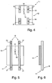
- FIG. 4 is an alternative embodiment of a frameless attachment to the embodiment according to the FIGS. 1 to 3 shown.
- This embodiment differs only to the effect that instead of two substantially over the height or width of the base body 12 extending fasteners 12, for example, four fasteners 18 are provided are. These fastening elements 18 are provided in particular in the region of attachment points 31, via which the solar element 11 on a substructure 46 (FIG. FIG. 8 ) is attached. These fasteners 18 may, for example, the same profile as the fasteners 18 in Figure 1 to 3 exhibit.
- the longitudinal axes of the individual fasteners 18 are aligned with each other, so that, for example, two arranged in a longitudinal axis fasteners 18 are aligned and the adjacent fasteners 18 parallel thereto.
- a plurality of fasteners 18 may be provided along the height or the width and aligned with each other in a line.
- the length of in FIG. 4 illustrated fasteners 18 is provided in such a way to at least small tolerances in the alignment of a substructure 46 (FIG. FIG. 8 ) with respect to the attachment points 31 to compensate.
- FIGS. 5 to 7 is another alternative embodiment of a frameless attachment of a solar element 11 to FIG. 1 shown.
- the fastening elements 18 deviating from the previously described embodiments are formed continuously and extend beyond the side edges 21, 22 of the main body 25 also.
- Such a configuration makes it possible that the attachment points 31 can lie outside the back or the rear surface of the main body 12.
- a complete support of the base body 12 over the height or the width of the base body 12 is provided on the fastening elements 18.
- the fasteners 18 in the embodiment according to the FIGS. 5 to 7 is formed, for example, as a fastening profile, which has a first C-shaped section 33, wherein the two mutually aligned legs 34 each form a contact surface 24 on their outer sides, via which the bonding to the back of the base body 12.
- a holding section 32 for example, adjoins the C-shaped profile 33, on which clamping and / or screw connections (not shown in more detail) for fixing to the substructure 46 engage.
- This holding portion 32 has, for example, two opposing C-shaped fixing portions 37.
- a bearing surface 38 is formed, so that the fastening element 18 can rest on a substructure 46.
- this support surface 38 may be formed as a further clamping or mounting surface.
- the embodiment of the above-described fastening element 18 is only an example and may include further different geometric embodiments.
- the fastening elements 18 are preferably used as extruded profiles, in particular aluminum extruded profiles. Alternatively, steel profiles or plastic profiles can be used.
- FIG. 8 For example, a side view of a solar system 41 is shown, which is arranged on a roof 42 of a building.
- This solar system 41 comprises a plurality of solar elements 11, which are fastened via an adapter profile 44 to a strut 47 and form a substructure 46.
- This substructure 46 can be provided, for example, on roof tiles or roof tiles, on roofs made of corrugated eternit or on a trapezoidal roof or the like.
- screw-clamp connections are preferably provided, which allow a simple and quick installation.
- the substructure 46 includes, for example, vertically extending struts 47, to which horizontally oriented adapter profiles 41 are fastened via, for example, a screw-clamp connection.
- the fastening elements 18 of the solar element 11 are fixed to the adapter profile 44.
- These adapter profiles 44 allow the reception of a plurality of juxtaposed solar elements 11.
- the adapter profiles 44 and the fastening elements 18 of the solar elements 11 is a simple alignment of a plurality of solar elements 11 allows each other so that to provide a closed as possible and large-scale arrangement of solar elements 11. Only a small gap is set between the individual solar elements 11 in order to allow moisture to drain between the mutually facing end faces of the base body 12 and to prevent the base body 12 from abutting one another when the heat expands.
- a plurality of parallel arranged adjacent fasteners 18 may be provided on the base body 12.
- fastening elements 18 may be aligned at right angles to one another, for example with respect to their fastening groove in the fastening profile, so that a fastening element is aligned at right angles to the side edges 21, 22 and a further fastening element parallel to the side edges 21, 22. Any combination thereof is also conceivable.
Abstract
Description
Die Erfindung betrifft ein Solarelement für Solaranlagen, insbesondere Photovoltaikanlagen, mit einem Grundkörper, der eine Vielzahl von miteinander verbundenen Solarzellen umfasst und an einer Rückseite des Grundkörpers eine Anschlussvorrichtung aufweist und mit zumindest einem Befestigungselement zur Montage an einer Unterkonstruktion.The invention relates to a solar element for solar systems, in particular photovoltaic systems, with a base body comprising a plurality of interconnected solar cells and having a connection device on a rear side of the base body and having at least one fastening element for mounting on a substructure.
Solche Solarelemente werden zur Herstellung von Photovoltaikanlagen eingesetzt, um das durch die Sonne gelieferte Energiepotential kostenlos und umweltfreundlich auszuschöpfen. Solche Photovoltaikanlagen werden beispielsweise auf Hausdächern oder in Fassaden sowie als Verschattung an Gebäuden integriert. Dadurch kann zum einen das Gebäude selbst mit Energie versorgt werden und zum anderen kann darüber hinaus erzeugte elektrische Energie in das öffentliche Stromnetz eingespeist werden.Such solar elements are used for the production of photovoltaic systems in order to exploit the energy potential delivered by the sun free of charge and in an environmentally friendly manner. Such photovoltaic systems are integrated, for example, on rooftops or in facades and as shading on buildings. As a result, on the one hand, the building itself can be supplied with energy and, on the other hand, about it In addition, generated electrical energy to be fed into the public grid.
Die Solarelemente für solche Anlagen umfassen mehrere Solarzellen, die miteinander elektrisch verbunden sind. Solche Solarzellen bestehen aus einem Halbleiter und werden zumeist aus Silizium hergestellt.The solar elements for such systems include a plurality of solar cells, which are electrically connected to each other. Such solar cells consist of a semiconductor and are mostly made of silicon.
Solche Solarelemente, wie aus einem Prospekt "RA zFaz Montagesysteme für PV-Module, Stand 27. Februar 2008 der Anmelderin hervorgeht, werden mit einem umlaufenden Rahmen versehen, wobei zwischen dem umlaufenden Rahmen, der aus Metall besteht und dem Grundkörper des Solarelementes ein Gummiprofil oder Dichtungsprofil vorgesehen ist. Diese Solarelemente werden mittels einer Klemmbefestigung über den Rahmen an einer Unterkonstruktion befestigt.Such solar elements, as shown in a brochure "RA zFaz mounting systems for PV modules, as of February 27, 2008 the applicant, are provided with a peripheral frame, wherein between the peripheral frame, which consists of metal and the main body of the solar element, a rubber profile or These solar elements are attached to a substructure by means of a clamp attachment over the frame.
Aus einem Prospekt der Firma SCHOTT Solar GmbH In 63755 Altenau geht ein Dünnschicht-Solarmodul "Schott ASI" hervor. Durch diese neue Dünnschichttechnologie soll mehr Energie auch bei ungünstigen Lichtverhältnissen erzielbar sein. Diese Dünnschicht-Solarmodule werden ebenfalls mit einem vollumfaufenden Rahmen versehen. Zwischen dem Rahmen und dem Grundkörper ist ein Gummielement oder Gummiprofil vorgesehen, um den Grundkörper dauerhaft elastisch in dem Rahmen einzubetten. Gleichzeitig ermöglicht dieser Rahmen eine Befestigung, wie dies beispielsweise aus dem vorstehend genannten Prospekt der Anmelderin bekannt ist. Diese Anordnung weist jedoch den Nachteil auf, dass insbesondere bei Dünnschicht-Solarmodulen zwischen dem Grundkörper und dem Rahmen Feuchtigkeit ansammelt und eine sogenannte Staunässe sich bildet. Eine solche Staunässe kann zur Oxidation der Halbleiterschicht führen, wodurch es zu Beschädigungen an den Solarzellen kommen kann.From a prospectus of the company SCHOTT Solar GmbH 63755 Altenau a thin-film solar module "Schott ASI" emerges. With this new thin-film technology, more energy should be achievable even in unfavorable lighting conditions. These thin-film solar modules are also provided with a vollumfenden frame. Between the frame and the body, a rubber element or rubber profile is provided to permanently embed the body elastically in the frame. At the same time this frame allows attachment, as is known for example from the above-mentioned brochure of the applicant. However, this arrangement has the disadvantage that moisture accumulates in particular in thin-film solar modules between the base body and the frame and forms a so-called waterlogging. Such waterlogging can lead to the oxidation of the semiconductor layer, which can lead to damage to the solar cells.
Deshalb liegt der Erfindung die Aufgabe zugrunde, ein Solarelement für Solaranlagen zu schaffen, welches eine einfache und schnelle Anordnung mehrerer Solarelemente an einer Unterkonstruktion zur Herstellung einer Solaranlage ermöglicht und die Bildung der Staunässe im Randbereich des Solarelementes vermeidet.The invention is therefore based on the object to provide a solar element for solar systems, which allows a simple and quick arrangement of several solar elements on a substructure for the production of a solar system and avoids the formation of waterlogging in the edge region of the solar element.
Diese Aufgabe wird erfindungsgemäß durch die Merkmale des Anspruchs 1 gelöst. Weitere vorteilhafte Ausgestaltungen und Weiterbildungen sind in den weiteren Ansprüchen angegeben.This object is achieved by the features of claim 1. Further advantageous embodiments and further developments are specified in the further claims.
Durch das erfindungsgemäße Solarelement, bei dem das zumindest eine an der Rückseite des Grundkörpers angeordnete Befestigungselement als rahmenlose Befestigung ausgebildet ist, wird verhindert, dass im Randbereich des Solarelementes sich Staunässe bilden kann, da der Randbereich nahezu vollständig oder vollständig frei von dem zumindest einen Befestigungselement ist. Diese rahmenlose Befestigung wird durch eine Klebeverbindung erzielt, durch welche das zumindest eine Befestigungselement an einer Rückseite am Grundkörper des Solarelementes angeordnet ist. Eine solche Ausgestaltung des Solarelementes ermöglicht eine einfache und schnelle Montage der Solarelemente an einer Unterkonstruktion, die auch für bisherige Solarelemente verwendet wurde. Durch die rahmenlose Befestigung der Solarelemente wird des Weiteren ermöglicht, dass eine höhere Flächenausnutzung gegeben ist, da die zwischen den aneinander grenzenden Solarelementen benötigte Fläche für die bisherige Rahmenkonstruktion zur Aufnahme und Fixierung der Solarelemente nicht mehr erforderlich ist. Darüber hinaus wird durch die Klebeverbindung eine dauerhaft elastische Lagerung des Grundkörpers zum zumindest einen Befestigungselement geschaffen.By virtue of the solar element according to the invention, in which the at least one fastening element arranged on the rear side of the main body is designed as a frameless fastening, it is prevented that waterlogging can form in the edge region of the solar element since the edge region is almost completely or completely free of the at least one fastening element , This frameless attachment is achieved by an adhesive bond, by which the at least one fastening element is arranged on a rear side on the base body of the solar element. Such an embodiment of the solar element allows a simple and quick installation of the solar elements on a substructure, which was also used for previous solar elements. The frameless attachment of the solar elements is further made possible that a higher area utilization is given because the space required between the adjoining solar panels for the previous frame construction for receiving and fixing the solar elements is no longer required. In addition, a permanently elastic mounting of the base body to the at least one fastening element is created by the adhesive bond.
Nach einer bevorzugten Ausgestaltung der Erfindung ist vorgesehen, dass wenigstens zwei, jeweils einem Befestigungspunkt zugeordnete Befestigungselemente zur Montage des Solarelementes an einer Unterkonstruktion vorgesehen sind. Durch diese zumindest zwei Befestigungselemente kann eine Fixierung des Solarelementes in einfacher Weise an der Unterkonstruktion ermöglicht sein. Diese zwei Befestigungselemente können beispielsweise an einem vordefinierten Kreuzungspunkt beziehungsweise Befestigungspunkt mit der Unterkonstruktion vorgesehen sein. Durch diese Ausgestaltung der Befestigungselemente werden sehr leichte Solarelemente hergestellt, die einen geringen Materialeinsatz für Befestigungselemente benötigen.According to a preferred embodiment of the invention, it is provided that at least two fastening elements, each associated with an attachment point, are provided for mounting the solar element on a substructure. By means of these at least two fastening elements, a fixation of the solar element can be made possible in a simple manner on the substructure. These two fastening elements can be provided, for example, at a predefined crossing point or fastening point with the substructure. This design of the fasteners very light solar panels are made, which require a low material usage for fasteners.
Nach einer alternativen Ausgestaltung der Erfindung ist vorgesehen, dass das zumindest eine Befestigungselement sich in der Länge über zwei Befestigungspunkte, die zur Montage des Solarelementes an einer Unterkonstruktion vorgesehen sind, erstreckt. Beispielsweise kann ein Befestigungselement als Befestigungsprofil vorgesehen sein. Eine solche Anordnung ermöglicht eine einfache Positionierung eines Befestigungselementes für beide Befestigungspunkte. Gleichzeitig ist die Ausrichtung des zumindest einen Befestigungselementes über zwei Befestigungspunkte einfach und schnell ermöglicht. Darüber hinaus kann eine Aussteifung des Grundkörpers erzielt werden.According to an alternative embodiment of the invention, it is provided that the at least one fastening element extends in length over two fastening points, which are provided for mounting the solar element on a substructure. For example, a fastening element may be provided as a fastening profile. Such an arrangement allows easy positioning of a fastener for both attachment points. At the same time the alignment of the at least one fastener via two attachment points is made easy and fast. In addition, a stiffening of the body can be achieved.
Nach einer weiteren bevorzugten Ausgestaltung der Erfindung ist vorgesehen, dass zumindest zwei Befestigungspunkte, die zur Montage des Solarelementes an einer Unterkonstruktion vorgesehen sind, innerhalb der rückseitigen Fläche des Grundkörpers liegen. Dadurch wird beispielsweise ermöglicht, dass alle vier Seitenkanten des Grundkörpers als Anschlusskanten für ein benachbartes Solarelement zur Verfügung stehen. Die Befestigungspunkte an dem zumindest einen Befestigungselement zur Unterkonstruktion sind bevorzugt nahe am Randbereich des Grundkörpers vorgesehen, um eine einfache Montage zu ermöglichen. Alternativ können diese auch bis zu einer Seitenkante des Grundkörpers vom Solarelement reichen, wobei die Gefahr der Staunässe insoweit nicht gegeben ist, da der Randbereich über die Dicke des Grundkörpers nicht eingerahmt ist.According to a further preferred embodiment of the invention, it is provided that at least two attachment points, which are provided for mounting the solar element on a substructure, lie within the rear surface of the base body. This makes it possible, for example, that all four side edges of the main body are available as connection edges for an adjacent solar element. The attachment points on the at least one fastening element to the substructure are preferably provided close to the edge region of the base body in order to allow easy mounting. Alternatively, these can also extend to a side edge of the main body of the solar element, the danger of waterlogging is not given so far, since the edge region is not framed over the thickness of the body.
Nach einer weiteren alternativen Ausgestaltung der Erfindung ist vorgesehen, dass die zumindest zwei Befestigungspunkte des zumindest einen Befestigungselementes außerhalb der rückseitigen Fläche des Grundkörpers liegen. Bei einer solchen Ausführungsform können die bevorzugt als Befestigungsprofil ausgebildeten Befestigungselemente, die an der Rückseite des Grundkörpers durch die Klebeverbindung befestigt sind, sich über die Seitenkanten des Grundkörpers hinaus erstrecken, so dass eine einfache Zugänglichkeit für die Befestigung des Befestigungselementes an der Unterkonstruktion gegeben ist. Beispielsweise kann ein durchgehendes Profilelement vorgesehen sein, welches sich gegenüber zwei parallelen Seitenkanten des Grundkörpers jeweils darüber hinaus erstreckt.According to a further alternative embodiment of the invention, it is provided that the at least two attachment points of the at least one fastening element lie outside the rear surface of the base body. In such an embodiment, preferably designed as a fastening profile fasteners that are attached to the back of the body by the adhesive bond, extend beyond the side edges of the body, so that easy accessibility for attachment of the fastener is given to the substructure. For example, a continuous profile element may be provided, which in each case extends beyond two parallel side edges of the main body.
Durch die durchgehenden Ausbildung des Befestigungselementes ist eine linienförmige Unterstützung gegeben. Dadurch kann auch eine verbesserte Kraftaufnahme aufgrund der größeren flächigen Verklebung gegeben sein. Alternativ kann auch vorgesehen sein, dass anstelle eines durchgehenden Befestigungsprofils zwei oder mehrere Profilabschnitte vorgesehen sind, die in derselben Längsachse liegen, um in Teilbereichen innerhalb der rückseitigen Fläche des Grundkörpers Freiräume zu schaffen.Due to the continuous design of the fastener a linear support is given. As a result, an improved force absorption due to the larger surface bond can be given. Alternatively it can also be provided that, instead of a continuous fastening profile, two or more profile sections are provided which lie in the same longitudinal axis in order to create free spaces in partial areas within the rear surface of the main body.
Nach einer bevorzugten Ausführungsform der Erfindung ist vorgesehen, dass das zumindest eine Befestigungselement als Befestigungsprofil ausgebildet ist, welches eine zumindest abschnittsweise sich erstreckende Anlagefläche als Klebefläche zur Ausbildung einer Klebeverbindung aufweist. Dadurch kann eine hinreichend große Klebefläche zur Verfügung gestellt werden, um eine sichere Anbindung des Befestigungselementes an der Rückseite des Grundkörpers vom Solarelement zu ermöglichen. Gleichzeitig dient eine solche Anlagefläche für eine verwindungssteife Aufnahme des Grundkörpers. Das Befestigungselement weist der Anlagefläche gegenüberliegend zumindest einen Profil abschnitt auf, um das Befestigungselement an der Unterkonstruktion zu fixieren.According to a preferred embodiment of the invention it is provided that the at least one fastening element is designed as a fastening profile, which has an at least partially extending contact surface as an adhesive surface for forming an adhesive bond. As a result, a sufficiently large adhesive surface can be made available in order to enable a secure connection of the fastening element to the back of the main body of the solar element. At the same time serves such a contact surface for a torsionally rigid recording of the body. The fastener has the contact surface opposite at least one profile section in order to fix the fastener to the substructure.
Nach einer weiteren bevorzugten Ausgestaltung der Erfindung ist vorgesehen, dass das zumindest eine Befestigungselement als Strangpressprofil mit wenigstens einem Anlageabschnitt und einem Halteabschnitt ausgebildet ist. In Abhängigkeit der Größe des Grundkörpers des Solarelementes und der Art der Befestigung kann in einfacher Weise die Länge des Befestigungselementes zugeschnitten werden. Somit kann eine kostengünstige Herstellung der Solarelemente erfolgen.According to a further preferred embodiment of the invention, it is provided that the at least one fastening element is designed as an extruded profile with at least one contact section and a holding section. Depending on the size of the base body of the solar element and the type of attachment, the length of the fastener can be tailored in a simple manner. Thus, a cost-effective production of the solar elements can take place.
Nach einer weiteren bevorzugten Ausgestaltung der Erfindung ist vorgesehen, dass an dem Befestigungsprofil ein Adapterprofil zur Montage an der Unterkonstruktion vorgesehen ist. Ein solches Adapterprofil verbindet das zumindest eine Befestigungsprofil zur Unterkonstruktion. Bevorzugt sind an einem Solarelement zwel Befestigungsprofile als Befestigungselemente parallel zueinander beabstandet vorgesehen. Das Adapterprofil erstreckt sich bevorzugt rechtwinklig zu dem zumindest einen Befestigungselement am Grundkörper des Solarelementes. Bevorzugt werden mehrere Solarelemente mit deren Befestigungselementen an dem Adapterprofil befestigt, welches wiederum an der Unterkonstruktion vormontiert ist.According to a further preferred embodiment of the invention it is provided that an adapter profile for mounting on the substructure is provided on the fastening profile. Such an adapter profile connects the at least one fastening profile to the substructure. Preferably fastening elements are provided as fasteners parallel to each other on a solar element zwel. The adapter profile preferably extends at right angles to the at least one Fastening element on the base body of the solar element. Preferably, several solar elements are fastened with their fastening elements on the adapter profile, which in turn is pre-mounted on the substructure.
Nach einer bevorzugten Ausgestaltung der Erfindung ist vorgesehen, dass das Solarelement als Dünnschichtmodul ausgebildet ist, bei dem der Grundkörper eine Schicht aus einem gehärteten Glas, eine Schicht aus Floatglas und dazwischen liegend eine Schicht aus Solarzellen umfasst. Die rahmenlose Befestigung durch Verklebung eignet sich insbesondere bei solchen Dünnschichtmodulen, da der Randbereich frei von Befestigungselementen gehalten ist und eine Staunässe vermieden wird.According to a preferred embodiment of the invention, it is provided that the solar element is designed as a thin-film module, wherein the base body comprises a layer of a hardened glass, a layer of float glass and a layer of solar cells lying therebetween. The frameless attachment by gluing is particularly suitable for such thin-film modules, since the edge region is kept free of fasteners and waterlogging is avoided.
Die Erfindung sowie weitere vorteilhafte Ausführungsformen und Weiterbildungen derselben werden im Folgenden anhand der in den Zeichnungen dargestellten Beispiele näher beschrieben und erläutert. Die der Beschreibung und den Zeichnungen zu entnehmenden Merkmale können einzeln für sich oder zu mehreren in beliebiger Kombination erfindungsgemäß angewandt werden. Es zeigen:
- Figur 1
- eine schematische Rückansicht eines erfindungsge- mäßen Solarelementes,
- Figur 2
- eine schematische Seitenansicht des Solarelementes gemäß
Figur 1 , - Figur 3
- eine weitere schematische Seitenansicht gemäß Fi- gur 1,
- Figur 4
- eine schematische Rückansicht einer alternativen Ausführungsform eines Solarelementes zu
Figur 1 , - Figur 5
- eine schematische Rückansicht einer weiteren alter- nativen Ausführungsform eines Solarelementes zu
Figur 1 , - Figur 6
- eine schematische Seitenansicht der Ausführungs- form gemäß
Figur 5 , - Figur 7
- eine weitere schematische Seitenansicht der Ausfüh- rungsform gemäß
Figur 5 und - Figur 8
- eine schematische Seitenansicht von Solarelementen einer Solaranlage, die auf einer Unterkonstruktion fi- xiert sind.
- FIG. 1
- a schematic rear view of a solar element according to the invention,
- FIG. 2
- a schematic side view of the solar element according to
FIG. 1 . - FIG. 3
- FIG. 2 shows a further schematic side view according to FIG. 1, FIG.
- FIG. 4
- a schematic rear view of an alternative embodiment of a solar element to
FIG. 1 . - FIG. 5
- a schematic rear view of another alternative embodiment of a solar element to
FIG. 1 . - FIG. 6
- a schematic side view of the embodiment according to
FIG. 5 . - FIG. 7
- a further schematic side view of the embodiment according to
FIG. 5 and - FIG. 8
- a schematic side view of solar panels of a solar system, which are fixed on a substructure xed.
In
An der Rückseite des Grundkörpers 12 bzw. an seiner rückseitigen Fläche ist zumindest ein Befestigungselement 18 vorgesehen. Das Befestigungselement 18 ist beispielsweise als Befestigungsprofil ausgebildet. Die Ausgestaltung dieses Befestigungselementes 18 geht aus den weiteren Seitenansichten gemäß
Die in den
Im Ausführungsbeispiel gemäß den
In
In den
Die Befestigungselemente 18 im Ausführungsbeispiel gemäß den
Die Ausgestaltung des vorbeschriebenen Befestigungselementes 18 ist nur beispielhaft und kann weitere verschiedene geometrische Ausführungsformen umfassen. Die Befestigungselemente 18 werden bevorzugt als Strangpressprofile, insbesondere Aluminiumstrangpressprofile, eingesetzt. Alternativ können auch Stahlprofile oder Kunststoffprofile eingesetzt werden.The embodiment of the above-described
In
Die Unterkonstruktion 46 umfasst beispielsweise vertikal verlaufende Streben 47, an welchen horizontal ausgerichtete Adapterprofile 41 über beispielsweise eine Schraub-Klemm-Verbindung befestigt sind. In den Befestigungspunkten 31 werden die Befestigungselemente 18 des Solarelementes 11 zum Adapterprofil 44 fixiert. Diese Adapterprofile 44 ermöglichen die Aufnahme von mehreren nebeneinander angeordneten Solarelementen 11. Durch diese kreuzweise Anordnung der Streben 47, der Adapterprofile 44 und der Befestigungselemente 18 der Solarelemente 11 ist eine einfache Ausrichtung von mehreren Solarelementen 11 zueinander ermöglicht, so dass eine möglichst geschlossene und großflächige Anordnung von Solarelementen 11 vorzusehen. Zwischen den einzelnen Solarelementen 11 wird nur ein geringer Spalt eingestellt, um zu ermöglichen, dass Feuchtigkeit zwischen den einander zugewandten Stirnseiten der Grundkörper 12 ablaufen kann und bei Wärmedehnungen ein Aneinanderliegen der Grundkörper 12 verhindert ist.The
Es versteht sich, dass alternativ zu den dargestellten Ausführungsformen auch mehrere parallel nebeneinander angeordnete Befestigungselemente 18 an dem Grundkörper 12 vorgesehen sein können. Alternativ kann in Abhängigkeit der Unterkonstruktion 46 auch vorgesehen sein, dass Befestigungselemente 18 beispielsweise bezüglich deren Befestigungsnut im Befestigungsprofil rechtwinklig zueinander ausgerichtet sind, so dass ein Befestigungselement rechtwinklig zu den Seitenkanten 21, 22 und ein weiteres Befestigungselement parallel zu den Seitenkanten 21, 22 ausgerichtet ist. Eine beliebige Kombination hiervon ist ebenfalls denkbar.It is understood that as an alternative to the illustrated embodiments, a plurality of parallel arranged
Claims (9)
Applications Claiming Priority (1)
| Application Number | Priority Date | Filing Date | Title |
|---|---|---|---|
| DE102008018077A DE102008018077A1 (en) | 2008-04-09 | 2008-04-09 | Solar element for solar systems |
Publications (1)
| Publication Number | Publication Date |
|---|---|
| EP2109153A2 true EP2109153A2 (en) | 2009-10-14 |
Family
ID=40929620
Family Applications (1)
| Application Number | Title | Priority Date | Filing Date |
|---|---|---|---|
| EP09005214A Withdrawn EP2109153A2 (en) | 2008-04-09 | 2009-04-09 | Solar element for solar assemblies |
Country Status (2)
| Country | Link |
|---|---|
| EP (1) | EP2109153A2 (en) |
| DE (1) | DE102008018077A1 (en) |
Cited By (5)
| Publication number | Priority date | Publication date | Assignee | Title |
|---|---|---|---|---|
| DE102010018837A1 (en) | 2010-04-28 | 2011-11-03 | Masdar Pv Gmbh | Method for mounting photovoltaic modules and photovoltaic array |
| WO2011054924A3 (en) * | 2009-11-05 | 2012-01-19 | Oerlikon Solar Ag, Trübbach | Method for fixing a mounting element to a photovoltaic module |
| EP2551918A1 (en) * | 2010-03-25 | 2013-01-30 | Sharp Kabushiki Kaisha | Solar cell module |
| JP2016525634A (en) * | 2013-06-03 | 2016-08-25 | ブルースコープ・スティール・リミテッドBluescope Steel Limited | Solar roof panels |
| US10505492B2 (en) | 2016-02-12 | 2019-12-10 | Solarcity Corporation | Building integrated photovoltaic roofing assemblies and associated systems and methods |
Family Cites Families (5)
| Publication number | Priority date | Publication date | Assignee | Title |
|---|---|---|---|---|
| DE4014200A1 (en) * | 1989-05-18 | 1990-11-22 | Telefunken Systemtechnik | Frameless solar generator - with solar cell laminate resting on profiles with silicone adhesive pads |
| DE4416884A1 (en) * | 1994-05-13 | 1995-11-23 | Daimler Benz Aerospace Ag | Solar generator panel mechanical attachment appts. |
| JPH09195473A (en) * | 1996-01-23 | 1997-07-29 | Sanyo Electric Co Ltd | Solar battery panel and solar battery device |
| DE10105718B4 (en) * | 2001-02-05 | 2005-11-10 | Zentrum für Sonnenenergie- und Wasserstoff-Forschung Baden-Württemberg | Photovoltaic module composite |
| DE102004055187B4 (en) * | 2004-11-16 | 2009-04-23 | Blitzstrom Gmbh | Moldings pair for photovoltaic modules |
-
2008
- 2008-04-09 DE DE102008018077A patent/DE102008018077A1/en not_active Withdrawn
-
2009
- 2009-04-09 EP EP09005214A patent/EP2109153A2/en not_active Withdrawn
Non-Patent Citations (1)
| Title |
|---|
| RA ZFAZ MONTAGESYSTEME FÜR PV-MODULE, 27 February 2008 (2008-02-27) |
Cited By (6)
| Publication number | Priority date | Publication date | Assignee | Title |
|---|---|---|---|---|
| WO2011054924A3 (en) * | 2009-11-05 | 2012-01-19 | Oerlikon Solar Ag, Trübbach | Method for fixing a mounting element to a photovoltaic module |
| EP2551918A1 (en) * | 2010-03-25 | 2013-01-30 | Sharp Kabushiki Kaisha | Solar cell module |
| EP2551918A4 (en) * | 2010-03-25 | 2014-04-30 | Sharp Kk | Solar cell module |
| DE102010018837A1 (en) | 2010-04-28 | 2011-11-03 | Masdar Pv Gmbh | Method for mounting photovoltaic modules and photovoltaic array |
| JP2016525634A (en) * | 2013-06-03 | 2016-08-25 | ブルースコープ・スティール・リミテッドBluescope Steel Limited | Solar roof panels |
| US10505492B2 (en) | 2016-02-12 | 2019-12-10 | Solarcity Corporation | Building integrated photovoltaic roofing assemblies and associated systems and methods |
Also Published As
| Publication number | Publication date |
|---|---|
| DE102008018077A1 (en) | 2009-11-05 |
Similar Documents
| Publication | Publication Date | Title |
|---|---|---|
| EP2210277B1 (en) | Photovoltaic unit comprising a matrix of frameless solar modules | |
| EP1734588B1 (en) | Roofing system | |
| DE102015119849A1 (en) | Photovoltaic system, module holder system and reflector | |
| EP2430377B1 (en) | Process for mounting an assembly of holding and fastening devices | |
| EP2307821A2 (en) | Retaining profile and sealing profile for board-shaped modules | |
| EP2317246B1 (en) | Multi-part frame for plate-shaped modules | |
| WO2007096158A1 (en) | Solar module system of the parabolic concentrator type | |
| DE202008017946U1 (en) | Module for the conversion of solar energy into electricity | |
| WO2010040780A1 (en) | Photovoltaic system, photovoltaic module and method for assembling a photovoltaic system | |
| EP2174074A1 (en) | Assembly frame for the integrated mounting of photovoltaic modules and solar collectors on buildings | |
| EP2118583A2 (en) | Device for fastening a retaining element to a roof surface | |
| EP2296190A2 (en) | Assembly, substructure and photovoltaic assembly | |
| EP2256821A2 (en) | Photovoltaic assembly made of thin film solar modules | |
| DE102008050529A1 (en) | Photovoltaic system, photovoltaic module, substructure and method for equipping a photovoltaic system | |
| EP2109153A2 (en) | Solar element for solar assemblies | |
| EP2508694A1 (en) | Carport | |
| EP2190030A2 (en) | Photovoltaic unit, photovoltaic system and method for manufacturing a photovoltaic unit | |
| EP2159847B1 (en) | System composed of a frameless thin solar module and a fixing clamp | |
| DE102009055948A1 (en) | Trapezoidal sheet profile element for constructing roof, has upper side including groove and bar or fastening functional element e.g. photovoltaic module, and/or base for accommodating functional element | |
| WO2010063811A2 (en) | Installation system | |
| WO2013182623A2 (en) | Installation arrangement for installing sheet‑like bodies on the roof of a structure | |
| DE112014004754T5 (en) | Mounting structure of a thin-film photovoltaic cell module | |
| DE10046134A1 (en) | Roof and facade shingle has carrier plate which extends over photovoltaic cell in at least one direction | |
| DE102010004117A1 (en) | Photovoltaic device for use on roof of building for converting solar energy into electrical power, has profiled rail whose part is positively enclosed from holding member, and attachment member fixed at back carrier element | |
| DE102010041161B4 (en) | Solar module mounting device |
Legal Events
| Date | Code | Title | Description |
|---|---|---|---|
| PUAI | Public reference made under article 153(3) epc to a published international application that has entered the european phase |
Free format text: ORIGINAL CODE: 0009012 |
|
| AK | Designated contracting states |
Kind code of ref document: A2 Designated state(s): AT BE BG CH CY CZ DE DK EE ES FI FR GB GR HR HU IE IS IT LI LT LU LV MC MK MT NL NO PL PT RO SE SI SK TR |
|
| RAP1 | Party data changed (applicant data changed or rights of an application transferred) |
Owner name: RALOS SOLAR GMBH |
|
| STAA | Information on the status of an ep patent application or granted ep patent |
Free format text: STATUS: THE APPLICATION IS DEEMED TO BE WITHDRAWN |
|
| 18D | Application deemed to be withdrawn |
Effective date: 20111101 |