EP3020877A1 - Vorrichtung zum spülen von flüssigkeitsleitungen, insbesondere trink- und/oder brauchwasserleitungen in gebäuden - Google Patents
Vorrichtung zum spülen von flüssigkeitsleitungen, insbesondere trink- und/oder brauchwasserleitungen in gebäuden Download PDFInfo
- Publication number
- EP3020877A1 EP3020877A1 EP15194051.7A EP15194051A EP3020877A1 EP 3020877 A1 EP3020877 A1 EP 3020877A1 EP 15194051 A EP15194051 A EP 15194051A EP 3020877 A1 EP3020877 A1 EP 3020877A1
- Authority
- EP
- European Patent Office
- Prior art keywords
- housing
- control module
- module
- flushing
- outlet
- Prior art date
- Legal status (The legal status is an assumption and is not a legal conclusion. Google has not performed a legal analysis and makes no representation as to the accuracy of the status listed.)
- Granted
Links
Images


Classifications
-
- B—PERFORMING OPERATIONS; TRANSPORTING
- B08—CLEANING
- B08B—CLEANING IN GENERAL; PREVENTION OF FOULING IN GENERAL
- B08B9/00—Cleaning hollow articles by methods or apparatus specially adapted thereto
- B08B9/02—Cleaning pipes or tubes or systems of pipes or tubes
- B08B9/027—Cleaning the internal surfaces; Removal of blockages
- B08B9/032—Cleaning the internal surfaces; Removal of blockages by the mechanical action of a moving fluid, e.g. by flushing
- B08B9/0321—Cleaning the internal surfaces; Removal of blockages by the mechanical action of a moving fluid, e.g. by flushing using pressurised, pulsating or purging fluid
- B08B9/0325—Control mechanisms therefor
-
- E—FIXED CONSTRUCTIONS
- E03—WATER SUPPLY; SEWERAGE
- E03B—INSTALLATIONS OR METHODS FOR OBTAINING, COLLECTING, OR DISTRIBUTING WATER
- E03B7/00—Water main or service pipe systems
- E03B7/07—Arrangement of devices, e.g. filters, flow controls, measuring devices, siphons or valves, in the pipe systems
- E03B7/08—Arrangement of draining devices, e.g. manual shut-off valves
Definitions
- the invention relates to a device for flushing liquid lines, especially drinking and / or service water pipes in buildings.
- the DE 10 2011 013 955 A1 one Method and a device for the automatic rinsing of liquid lines, especially drinking water pipes known.
- the device shown there includes means for measuring the temperature, means for detecting, storing and evaluating the measured temperature and means for performing a rinsing operation, which are arranged together on a base frame, and is relatively complex due to their construction and also requires a relatively large amount of space their assembly.
- the invention has for its object to provide a device of the type specified, on the one hand is very compact and also allows a common as well as separate assembly of rinsing and control components, whereby an individual adaptation to existing space conditions is ensured, and a relatively easy connection to the respective liquid line guaranteed.
- the device according to the invention is formed from a flushing module having a housing and can be connected to the respective fluid line and also a control module having a housing for connection and detection, evaluation or control of shut-off and detection components of at least one flushing module.
- the housings of the flushing module and of the control module are designed to be connectable to one another. Due to the special compact design of the device relatively little space is required for individual installation of the same, which is also ensured by the two individual modules separate mounting the same at different locations.
- the flushing module has a fitting housing with two connection stubs arranged coaxially with one another and a plurality of receiving stubs extending transversely thereto between the connection stubs and receiving bores for the shut-off and detection components extending therein.
- the connection piece at one end of the fitting housing with the respective liquid line for hot or cold liquids is connectable and the connection piece at the other end of the fitting housing opens into a connectable to the public sewer network sewage outlet or in a connectable to a gray water tank greywater outlet.
- the fitting housing may preferably be formed in one piece.
- the shut-off and detection components in the intake ports may be a manual shut-off valve, a temperature sensor, an electromagnetic purge valve, and a volume sensor. Due to the manually operated shut-off valve, the flushing module can be shut off against unintentional flushing under certain conditions.
- the temperature sensor in conjunction with the control module allows a fully automatic flushing of the respective line as a function of the temperature by opening the normally closed electromagnetic flush valve.
- the volume sensor detects the complete flushing volume, wherein after reaching the predetermined by the control module flushing volume, the flush valve is closed.
- connection piece at the other end of the fitting housing and the sewage or greywater outlet a free outlet with two coaxially arranged connection piece can be provided.
- the one connecting piece of the free outlet can be connected to the connecting piece at the other end of the fitting housing and the other connection piece of the free outlet can flow into the sewage or gray water outlet.
- a bell trap can be provided, are avoided by the unpleasant odors from the sewage or gray water outlet.
- the free outlet may preferably have an overflow monitoring device, which may be, for example, a float switch.
- the control module may comprise contact elements and / or connection sockets for at least one temperature sensor, a volume sensor, a flushing valve and an overflow monitoring device.
- the control module can also have contact elements and / or connection sockets for at least one further external temperature sensor and / or a further external volume sensor. This makes it possible to connect a further temperature sensor and / or a further volume sensor, which can or may be provided at any point of the liquid line, to the control module and those obtained from the further temperature sensor and / or a further volume sensor Values to be considered.
- control module can have a USB connection socket, via which the control module can be read out or via which data can be transmitted to the control module. Furthermore, the control module can be connected to a building control device of a building management system via the USB connection socket.
- the housing of the flushing module and the housing of the control module can preferably be formed from a PU foam. This ensures especially in the flushing module for a good sound and heat insulation.
- the housing of the flushing module and the housing of the control module can be connected by means of a plurality of snaps, whereby a fast and accurate connection is ensured.
- At least one longitudinal groove in the region of at least one of the lateral edges may be formed on the front side of the housing of the control module, in which the housing of the flushing module engages in a form-fitting manner with a spring integrally formed on at least one of the lateral edges on the rear side of the housing of the flushing module can.
- the interlocking engagement improves the stability of the two-piece device after assembly of the two housings and increases the strength of the connection.
- a longitudinal groove may be provided on each of the lateral edges of the housing of the control module, wherein on the back of the housing of the flushing module in each case a longitudinal spring may be formed on each of the lateral edges of the housing of the flushing module.
- this allows the flushing module to be connected either to the left or to the right with the control module.
- top and the bottom of the housing of the flushing module and in the top and bottom of the housing of the control module can be formed over a portion of the depth of the housing extending T-groove-like slots, with which an attachment of the device to a wall or on a other place is possible.
- device 1 is provided for flushing liquid lines, especially drinking and / or service water pipes in buildings and provides if necessary, ie in bacteria or germ formation in the water or the like. due, for example, to low water temperatures, for automatic flushing of the respective fluid line.
- the device 1 consists on the one hand of a housing 2 exhibiting and with the respective liquid line (not shown) connectable Spülmodul 3 and on the other hand from a likewise a housing 4 exhibiting control module 5 for connection and detection, for evaluation or control of shut-off and Detection components of at least one flushing module 3.
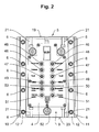
- the in Fig. 1 and 2 and 5 to 7 illustrated control module 5 shows an embodiment thereof for connection and for the detection, evaluation or control of shut-off and detection components for two rinsing modules 3, wherein each flush module 3 takes over the flushing of separate fluid lines (eg a hot water pipe and a cold water pipe).
- the housings 2, 4 of the flushing module 3 and the control module 5, which preferably consist of a PU foam for insulation purposes (sound and temperature), are designed to be connectable to one another.
- the connection of the two housings 2, 4 via a plurality of snaps, the items 6, 7 are held in the PU foam (see in particular Fig. 5 and 6 ).
- An additional backup can be done by means of screws (not shown), which extend through holes 8 in the housing 2 of the flushing module 3 into the housing 4 of the control module 5.
- the particular compact design of the device 1, which requires relatively little space, allows an individual assembly of the same.
- the positive interlocking improves the stability of the two-part device 1 after assembly of the housings 2, 4 and increases the strength of the connection.
- rinsing module 3 In Fig. 1 only one rinsing module 3 is mounted on the right side of the control module 5. The grooves 12 and the springs 16 also allow attachment of the flushing module 3 on the left side of the control module 5.
- the control module 5 shown is, as already mentioned above, however, also provided for receiving two rinsing modules 3, wherein also a stringing or Chaining of several rinsing modules 3 and several control modules 5 with connection options for a rinsing module 3 or two rinsing modules 3 is possible.
- T-slot nuts 23 are inserted into the T-slot slots 21, which clamp over the heads of screws 24 each have a leg 25 of the bracket 22 and the housing 2, 4.
- the flushing module 3 has a preferably integrally formed fitting housing 26 with two coaxially arranged connecting pieces 27, 28 and a plurality of connecting pieces 27, 28 extending transversely thereto receiving socket 29, 30, 31, 32 with therein receiving holes 33, 34, 35, 36 for the shut-off and detection components on.
- the connecting piece 27 at one end of the fitting housing 26 is connectable to the respective liquid line and the connecting piece 28 opens at the other end of the fitting housing 26 in a connectable to the public sewer network sewage outlet or in a connectable to a gray water tank greywater outlet (not shown).
- a free outlet 37 is provided with two coaxially arranged connection piece 38, 39, wherein the one connecting piece 38 of the free outlet 37 with the connecting piece 28 at the other end of the fitting housing 26 is connected and the other connection piece 39 of the free outlet 37 opens into the sewage or gray water outlet.
- a bell trap 40 is provided in the free outlet 37.
- the free outlet 37 has an overflow monitoring device 41, which may be, for example, a float switch.
- a manual shut-off valve 42 in the receiving port 30, a temperature sensor 43, in the receiving port 31, an electromagnetic flush valve 44 and the receiving port 32, a flow sensor 45 is inserted, wherein the arrangement in the valve body 26 of the order corresponding to the previous list of the connecting piece 27 for the respective liquid line to the connecting piece 28 for the free outlet 37 corresponds.
- the control module 5 To connect the shut-off and detection components of the flushing module 3, i. the temperature sensor 43, the electromagnetic flush valve 44 and the volume sensor 45 and the overflow monitoring device 41, with the control module 5, the control module 5 contact elements (not shown) and / or connection sockets 46, 47, 48, 49.
- a further external temperature sensor and / or a further external volume sensor is required, which can or may be provided at any point of the fluid line.
- the control module 5 contact elements (also not shown) and / or connection sockets 50, 51 on.
- control module 5 has a USB connection socket 52 and / or a Bluetooth interface and / or an NFC interface, via which the acquired data can be read out by the control module 5 or can be transmitted to the control module via the presettings.
- the USB port 52 and / or the Bluetooth interface and / or the NFC interface may or may also be used to connect the control module 5 with a building control device of a building control system.
- a flushing process of the respective liquid line can be initiated by the control module 5, taking into account the line usage with respect to the time, the temperature and possibly the volume consumed in the respective liquid line (only with a further external volume sensor). This ensures hygienic operation and optimizes flushing quantities, since all parameters, such as temperature, flushing times and quantities, are recorded in the control module 5.
Landscapes
- Engineering & Computer Science (AREA)
- Health & Medical Sciences (AREA)
- Life Sciences & Earth Sciences (AREA)
- Hydrology & Water Resources (AREA)
- Public Health (AREA)
- Water Supply & Treatment (AREA)
- Mechanical Engineering (AREA)
- Devices For Dispensing Beverages (AREA)
- Domestic Plumbing Installations (AREA)
Abstract
Description
- Die Erfindung betrifft eine Vorrichtung zum Spülen von Flüssigkeitsleitungen, insbesondere Trink- und/oder Brauchwasserleitungen in Gebäuden.
- In Flüssigkeitsleitungen, insbesondere Trink- und Brauchwasserleitungen sind zur Vermeidung einer Kontamination des Wasser durch Bakterien o.dgl. z.B. durch längere Stagnationszeiten des Wassers in den Leitungen geeignete Sicherheitseinrichtungen erforderlich. Vorschriften dazu sind in der bundesdeutschen Trinkwasserverordnung zusammengefasst. Vor allem in größeren Gebäuden, wie eine Mehrzahl von Wohneinheiten aufweisende Wohnhäuser, Alten- und Pflegeheime, Krankenhäuser, Schulen, Turnhallen, Hotels usw., aber auch kleinere Gebäude, wie Ein- oder Zweifamilienhäuser usw. muss jederzeit ein hygienekonformer Betrieb der Trink- und Brauchwasserleitungen gewährleistet sein.
- Um diesen Anforderungen gerecht zu werden, ist es bekannt, die betreffenden Leitungen durch Spülen derselben von derartigen Kontaminationen zu befreien. So ist beispielsweise in der
DE 10 2011 013 955 A1 ein Verfahren und eine Vorrichtung zum selbsttätigen Spülen von Flüssigkeitsleitungen, insbesondere Trinkwasserleitungen bekannt. Die dort dargestellte Vorrichtung beinhaltet Mittel zur Messung der Temperatur, Mittel zum Erfassen, Speichern und Auswerten der gemessenen Temperatur und Mittel zur Durchführung eines Spülvorgangs, die gemeinsam auf einem Grundrahmen angeordnet sind, und ist aufgrund ihrer Konstruktion relativ aufwändig und benötigt zudem relativ viel Platz zu deren Montage. - Der Erfindung liegt die Aufgabe zugrunde, eine Vorrichtung der angegebenen Gattung zu schaffen, die einerseits sehr kompakt ausgebildet ist und zudem eine gemeinsame wie auch getrennte Montage der Spül- und Steuerkomponenten ermöglicht, wodurch eine individuelle Anpassung an bestehende Platzverhältnisse gewährleistet ist, und die eine relativ einfache Anbindung an die jeweilige Flüssigkeitsleitung gewährleistet.
- Diese Aufgabe wird erfindungsgemäß durch eine Vorrichtung mit den Kennzeichnungsmerkmalen des Patentanspruchs 1 gelöst.
- Zweckmäßige Weiterbildungen der Erfindung sind in den Unteransprüchen gekennzeichnet.
- Die erfindungsgemäße Vorrichtung wird aus einem ein Gehäuse aufweisendes und mit der jeweiligen Flüssigkeitsleitung verbindbaren Spülmodul sowie einem ebenfalls ein Gehäuse aufweisendes Steuermodul zum Anschluss und zur Erfassung, zur Auswertung bzw. zur Steuerung von Absperr- und Erfassungskomponenten mindestens eines Spülmoduls gebildet. Dabei sind die Gehäuse des Spülmoduls und des Steuermoduls miteinander verbindbar ausgebildet. Durch die besondere kompakte Ausbildung der Vorrichtung wird zur individuellen Montage derselben relativ wenig Platz benötigt, wobei zudem durch die beiden Einzelmodule eine getrennte Montage derselben an unterschiedlichen Orten gewährleistet ist.
- Das Spülmodul weist ein Armaturengehäuse mit zwei koaxial zueinander angeordneten Anschlussstutzen und mehreren zwischen den Anschlussstutzen quer dazu verlaufenden Aufnahmestutzen mit darin verlaufenden Aufnahmebohrungen für die Absperr- und Erfassungskomponenten auf. Dabei ist der Anschlussstutzen am einen Ende des Armaturengehäuses mit der jeweiligen Flüssigkeitsleitung für warme oder kalte Flüssigkeiten verbindbar und der Anschlussstutzen am anderen Ende des Armaturengehäuses mündet in einen an das öffentliche Abwassernetz anschließbaren Abwasserabgang oder in einen an einen Grauwassertank anschließbaren Grauwasserabgang.
- Das Armaturengehäuse kann vorzugsweise einstückig ausgebildet sein. Durch diese Ausbildung können die bei Verschraubungen oder sonstigen Verbindungen möglich werdenden Undichtigkeiten weitestgehend ausgeschlossen werden.
- Die Absperr- und Erfassungskomponenten in den Aufnahmestutzen können ein handbetätigtes Absperrventil, ein Temperatursensor, ein elektromagnetisches Spülventil und ein Volumensensor sein. Durch das handbetätigte Absperrventil kann unter bestimmten Voraussetzungen das Spülmodul gegen unbeabsichtigtes Spülen abgesperrt werden. Der Temperatursensor in Verbindung mit dem Steuermodul ermöglicht eine vollautomatische Spülung der jeweiligen Leitung in Abhängigkeit der Temperatur durch Öffnen des stromlos geschlossenen elektromagnetischen Spülventils. Der Volumensensor erfasst das komplette Spülvolumen, wobei nach dem Erreichen des von dem Steuermodul vorgegebenen Spülvolumens das Spülventil geschlossen wird.
- Zwischen dem Anschlussstutzen am anderen Ende des Armaturengehäuses und dem Abwasser- oder Grauwasserabgang kann ein freier Auslauf mit zwei koaxial zueinander angeordneten Anschlussstutzen vorgesehen sein. Der eine Anschlussstutzen des freien Auslaufs kann mit dem Anschlussstutzen am anderen Ende des Armaturengehäuses verbunden sein und der andere Anschlussstutzen des freien Auslaufs kann in den Abwasser- oder Grauwasserabgang münden. In dem freien Auslauf kann ein Glockengeruchsverschluss vorgesehen sein, durch den unangenehme Gerüche aus dem Abwasser- oder Grauwasserabgang vermieden werden.
- Zur Erkennung eines Rückflusses aus dem Abwassernetz oder aus dem Grauwassertank kann der freie Auslauf vorzugsweise eine Überlauf-Überwachungseinrichtung aufweisen, die beispielsweise ein Schwimmerschalter sein kann.
- Für eine Verbindung von dem Spülmodul zu dem Steuermodul kann das Steuermodul Kontaktelemente und/oder Anschlussbuchsen für mindestens einen Temperatursensor, einen Volumensensor, ein Spülventil und eine Überlauf-Überwachungseinrichtung aufweisen.
- Das Steuermodul kann auch Kontaktelemente und/oder Anschlussbuchsen für mindestens einen weiteren externen Temperatursensor und/oder einen weiteren externen Volumensensor aufweisen. Dadurch ist die Möglichkeit gegeben, einen weiteren Temperatursensor und/oder einen weiteren Volumensensor, der bzw. die an einer beliebigen Stelle der Flüssigkeitsleitung vorgesehen sein kann bzw. können, an das Steuermodul anzuschließen und die von dem weiteren Temperatursensor und/oder einen weiteren Volumensensor erhaltenen Werte zu berücksichtigen.
- Ferner kann das Steuermodul eine USB-Anschlussbuchse aufweisen, über die das Steuermodul ausgelesen werden kann bzw. über die Daten auf das Steuermodul übertragen werden können. Des Weiteren kann über die USB-Anschlussbuchse das Steuermodul mit einer Gebäudesteuereinrichtung einer Gebäudeleittechnik verbunden werden.
- Das Gehäuse des Spülmoduls und das Gehäuse des Steuermoduls können vorzugsweise aus einem PU-Schaum gebildet sein. Dies sorgt insbesondere bei dem Spülmodul für eine gute Schall- und Wärmeisolierung.
- Ferner können das Gehäuse des Spülmoduls und das Gehäuse des Steuermoduls mittels einer Mehrzahl von Druckknöpfen verbindbar sein, wodurch eine schnelle und exakte Verbindung gewährleistet ist.
- Auf der Vorderseite des Gehäuses des Steuermoduls kann mindestens eine längsverlaufende Nut im Bereich mindestens eines der seitlichen Ränder eingeformt sein, in die das Gehäuse des Spülmoduls mit einer an mindestens einem der seitlichen Ränder auf der Rückseite des Gehäuses des Spülmoduls längsverlaufende, einstückig angeformten Feder formschlüssig eingreifen kann. Durch das formschlüssige Ineinandergreifen wird die Stabilität der zweiteiligen Vorrichtung nach dem Zusammensetzen der beiden Gehäuse verbessert und die Festigkeit der Verbindung gesteigert.
- Auf der Vorderseite des Gehäuses des Steuermoduls kann jeweils eine längsverlaufende Nut an jedem der seitlichen Ränder des Gehäuses des Steuermoduls vorgesehen sein, wobei auf der Rückseite des Gehäuses des Spülmoduls jeweils eine längsverlaufende Feder an jedem der seitlichen Ränder des Gehäuses des Spülmoduls angeformt sein kann. Dies ermöglicht einerseits, dass das Spülmodul entweder links oder rechts mit dem Steuermodul verbunden werden kann. Andererseits ist es durchaus möglich, zwei Spülmodule mit einem Steuermodul zu verbinden, wobei das Steuermodul dann sämtliche Kontaktelemente und/oder Anschlussbuchsen für zwei Spülmodule aufweist.
- In die Oberseite und die Unterseite des Gehäuses des Spülmoduls und in die Oberseite und die Unterseite des Gehäuses des Steuermoduls können sich über einen Teilbereich der Tiefe der Gehäuse erstreckende T-nutenartige Schlitze eingeformt sein, mit denen eine Befestigung der Vorrichtung an einer Wand oder an einem sonstigen Ort möglich ist.
- Nachfolgend wird anhand der Zeichnung ein Ausführungsbeispiel der erfindungsgemäßen Vorrichtung näher erläutert.
- Es zeigen
- Fig. 1
- eine Vorderansicht auf die Vorrichtung,
- Fig. 2
- eine Vorderansicht auf das Steuermodul der Vorrichtung,
- Fig. 3
- eine Vorderansicht auf das Spülmodul der Vorrichtung,
- Fig. 4
- einen Schnitt nach der Linie IV-IV in
Fig. 3 , - Fig. 5
- eine perspektivische Ansicht der Vorrichtung vor dem Zusammenfügen des Spülmoduls mit dem Steuermodul,
- Fig. 6
- eine Draufsicht auf die Vorrichtung vor dem Zusammenfügen des Spülmoduls mit dem Steuermodul und
- Fig. 7
- eine Draufsicht auf die Vorrichtung nach dem Zusammenfügen des Spülmoduls mit dem Steuermodul.
- Die in
Fig. 1 bis 7 dargestellte Vorrichtung 1 ist zum Spülen von Flüssigkeitsleitungen, insbesondere Trink- und/oder Brauchwasserleitungen in Gebäuden vorgesehen und sorgt bei Bedarf, d.h. bei Bakterien- und Keimbildung im Wasser o.dgl. aufgrund von beispielsweise zu geringen Wassertemperaturen, für ein automatisches Spülen der jeweiligen Flüssigkeitsleitung. - Die Vorrichtung 1 besteht einerseits aus einem ein Gehäuse 2 aufweisendes und mit der jeweiligen Flüssigkeitsleitung (nicht dargestellt) verbindbarem Spülmodul 3 sowie andererseits aus einem ebenfalls ein Gehäuse 4 aufweisendes Steuermodul 5 zum Anschluss und zur Erfassung, zur Auswertung bzw. zur Steuerung von Absperr- und Erfassungskomponenten mindestens eines Spülmoduls 3. Das in
Fig. 1 und2 sowie 5 bis 7 dargestellte Steuermodul 5 zeigt ein Ausführungsbeispiel desselben zum Anschluss und zur Erfassung, zur Auswertung bzw. zur Steuerung von Absperr- und Erfassungskomponenten für zwei Spülmodule 3, wobei jedes Spülmodul 3 das Spülen separater Flüssigkeitsleitungen übernimmt (z.B. einer Warmwasserleitung und einer Kaltwasserleitung). - Die Gehäuse 2, 4 des Spülmoduls 3 und des Steuermoduls 5, die zu Isolationszwecken (Schall und Temperatur) vorzugsweise aus einem PU-Schaum bestehen, sind miteinander verbindbar ausgebildet. Die Verbindung der beiden Gehäuse 2, 4 erfolgt über eine Mehrzahl von Druckknöpfen, deren Einzelteile 6, 7 in dem PU-Schaum gehalten sind (siehe insbesondere
Fig. 5 und6 ). Eine zusätzliche Sicherung kann mittels Schrauben (nicht dargestellt) erfolgen, die sich durch Bohrungen 8 im Gehäuse 2 des Spülmoduls 3 bis in das Gehäuse 4 der Steuermoduls 5 erstrecken. Die besondere kompakte Ausbildung der Vorrichtung 1, die relativ wenig Platz benötigt, ermöglicht eine individuelle Montage derselben. Die Zweiteiligkeit der Vorrichtung 1 ermöglicht ggf. aber auch eine getrennte Montage der Module 3, 5 an unterschiedlichen Orten. - Auf der Vorderseite 9 des Gehäuses 4 des Steuermoduls 5 sind im Bereich der seitlichen Ränder 10, 11 jeweils eine längsverlaufende Nut 12 eingeformt, in die das Gehäuse 2 des Spülmoduls 3 mit einer seiner an den seitlichen Rändern 13, 14 auf der Rückseite 15 des Gehäuses 2 des Spülmoduls 3 längsverlaufenden, einstückig angeformten Federn 16 formschlüssig eingreift. Wie bereits erwähnt, wird durch das formschlüssige Ineinandergreifen die Stabilität der zweiteiligen Vorrichtung 1 nach dem Zusammensetzen der Gehäuse 2, 4 verbessert und die Festigkeit der Verbindung gesteigert.
- In
Fig. 1 ist lediglich ein Spülmodul 3 auf der rechten Seite des Steuermoduls 5 angebracht. Die Nuten 12 und die Federn 16 ermöglichen auch eine Anbringung des Spülmoduls 3 auf der linken Seite des Steuermoduls 5. Das dargestellte Steuermodul 5 ist, wie bereits oben erwähnt, jedoch auch zur Aufnahme von zwei Spülmodulen 3 vorgesehen, wobei zudem auch eine Aneinanderreihung bzw. Verkettung von mehreren Spülmodulen 3 und mehreren Steuermodulen 5 mit Anschlussmöglichkeiten für ein Spülmodul 3 oder zwei Spülmodule 3 möglich ist. - Zur Befestigung der Vorrichtung 1 an einer Wand oder auch an einem anderen Ort sind in die Oberseite 17 und die Unterseite 18 des Gehäuses 2 des Spülmoduls 3 und in die Oberseite 19 und die Unterseite 20 des Gehäuses 4 des Steuermoduls 5 sich über einen Teilbereich der Tiefe der Gehäuse 2, 4 erstreckende T-nutenartige Schlitze 21 eingeformt, über die Haltewinkel 22 auf den Oberseiten 17, 19 und Unterseiten 18, 20 der Gehäuse 2, 4 befestigt werden können. Dazu sind in die T-nutenartigen Schlitze 21 T-Nutensteine 23 eingesetzt, die über die Köpfe von Schrauben 24 jeweils einen Schenkel 25 der Haltewinkel 22 und die Gehäuse 2, 4 einspannen.
- Das Spülmodul 3 weist ein vorzugsweise einstückig ausgebildetes Armaturengehäuse 26 mit zwei koaxial zueinander angeordneten Anschlussstutzen 27, 28 und mehreren zwischen den Anschlussstutzen 27, 28 quer dazu verlaufenden Aufnahmestutzen 29, 30, 31, 32 mit darin verlaufenden Aufnahmebohrungen 33, 34, 35, 36 für die Absperr- und Erfassungskomponenten auf. Der Anschlussstutzen 27 am einen Ende des Armaturengehäuses 26 ist mit der jeweiligen Flüssigkeitsleitung verbindbar und der Anschlussstutzen 28 am anderen Ende des Armaturengehäuses 26 mündet in einen an das öffentliche Abwassernetz anschließbaren Abwasserabgang oder in einen an einen Grauwassertank anschließbaren Grauwasserabgang (nicht dargestellt).
- Zwischen dem Anschlussstutzen 28 am anderen Ende des Armaturengehäuses 26 und dem Abwasser- oder Grauwasserabgang ist ein freier Auslauf 37 mit zwei koaxial zueinander angeordneten Anschlussstutzen 38, 39 vorgesehen, wobei der eine Anschlussstutzen 38 des freien Auslaufs 37 mit dem Anschlussstutzen 28 am anderen Ende des Armaturengehäuses 26 verbunden ist und der andere Anschlussstutzen 39 des freien Auslaufs 37 in den Abwasser- oder Grauwasserabgang mündet. Zur Vermeidung von unangenehmen Gerüchen ist in dem freien Auslauf 37 ein Glockengeruchsverschluss 40 vorgesehen.
- Zur Erkennung eines Rückflusses aus dem Abwassernetz oder aus dem Grauwassertank weist der freie Auslauf 37 eine Überlauf-Überwachungseinrichtung 41 auf, die beispielsweise ein Schwimmerschalter sein kann.
- Als Absperr- und Erfassungskomponenten sind in den Aufnahmestutzen 29 ein handbetätigtes Absperrventil 42, in den Aufnahmestutzen 30 ein Temperatursensor 43, in den Aufnahmestutzen 31 ein elektromagnetisches Spülventil 44 und in den Aufnahmestutzen 32 ein Volumenstromsensor 45 eingesetzt, wobei deren Anordnung in dem Armaturengehäuse 26 der Reihenfolge entsprechend der vorherigen Aufzählung von dem Anschlussstutzen 27 für die jeweilige Flüssigkeitsleitung bis zum Anschlussstutzen 28 für den freien Auslauf 37 entspricht.
- Zur Verbindung der Absperr- und Erfassungskomponenten des Spülmoduls 3, d.h. des Temperatursensors 43, des elektromagnetischen Spülventils 44 und des Volumensensors 45 sowie der Überlauf-Überwachungseinrichtung 41, mit dem Steuermodul 5 weist das Steuermodul 5 Kontaktelemente (nicht dargestellt) und/oder Anschlussbuchsen 46, 47, 48, 49 auf.
- Um zusätzlich die Temperatur und/oder den Volumenstrom innerhalb der Flüssigkeitsleitung zu erfassen und zu berücksichtigen, ist ein weiterer externer Temperatursensor und/oder ein weiterer externer Volumensensor erforderlich, der bzw. die an einer beliebigen Stelle der Flüssigkeitsleitung vorgesehen sein kann bzw. können. Auch dafür weist das Steuermodul 5 Kontaktelemente (ebenfalls nicht dargestellt) und/oder Anschlussbuchsen 50, 51 auf.
- Ferner weist das Steuermodul 5 eine USB-Anschlussbuchse 52 und/oder eine Bluetooth-Schnittstelle und/oder eine NFC-Schnittstelle auf, über die erfasste Daten von dem Steuermodul 5 ausgelesen werden können bzw. über die Voreinstellungen auf das Steuermodul übertragen werden können. Die USB-Anschlussbuchse 52 und/oder die Bluetooth-Schnittstelle und/oder die NFC-Schnittstelle kann bzw. können aber auch zur Verbindung des Steuermoduls 5 mit einer Gebäudesteuereinrichtung einer Gebäudeleittechnik genutzt werden.
- Mit der erfindungsgemäßen Vorrichtung 1 kann ein Spülvorgang der jeweiligen Flüssigkeitsleitung unter Berücksichtigung der Leitungsnutzung in Bezug auf die Zeit, die Temperatur und ggf. des verbrauchten Volumens in der jeweiligen Flüssigkeitsleitung (nur bei einem weiteren externen Volumensensor) durch das Steuermodul 5 eingeleitet werden. Dadurch wird ein hygienischer Betrieb sichergestellt und Spülmengen optimiert, da sämtliche Parameter, wie Temperatur, Spülzeitpunkte und - mengen in dem Steuermodul 5 protokoliert werden.
Claims (17)
- Vorrichtung (1) zum Spülen von Flüssigkeitsleitungen, insbesondere Trink- und/oder Brauchwasserleitungen in Gebäuden,
dadurch gekennzeichnet,
dass die Vorrichtung (1) aus einem ein Gehäuse (2) aufweisendes und mit der jeweiligen Flüssigkeitsleitung verbindbaren Spülmodul (3) sowie einem ebenfalls ein Gehäuse (4) aufweisendes Steuermodul (5) zum Anschluss und zur Erfassung, zur Auswertung bzw. zur Steuerung von Absperr- und Erfassungskomponenten mindestens eines Spülmoduls (3) gebildet wird, wobei die Gehäuse (2, 4) des Spülmoduls (3) und des Steuermoduls (5) miteinander verbindbar ausgebildet sind. - Vorrichtung nach Anspruch 1,
dadurch gekennzeichnet,
dass das Spülmodul (3) ein Armaturengehäuse (26) mit zwei koaxial zueinander angeordneten Anschlussstutzen (27, 28) und mehreren zwischen den Anschlussstutzen (27, 28) quer dazu verlaufenden Aufnahmestutzen (29, 30, 31, 32) mit darin verlaufenden Aufnahmebohrungen (33, 34, 35, 36) für die Absperr- und Erfassungskomponenten aufweist, wobei der Anschlussstutzen (27) am einen Ende des Armaturengehäuses (26) mit der jeweiligen Flüssigkeitsleitung verbindbar ist und der Anschlussstutzen (28) am anderen Ende des Armaturengehäuses (26) in einen an das öffentliche Abwassernetz anschließbaren Abwasserabgang oder in einen an einen Grauwassertank anschließbaren Grauwasserabgang mündet. - Vorrichtung nach Anspruch 1 oder 2,
dadurch gekennzeichnet,
dass das Armaturengehäuse (26) einstückig ausgebildet ist. - Vorrichtung nach einem der Ansprüche 1 bis 3,
dadurch gekennzeichnet,
dass die Absperr- und Erfassungskomponenten in den Aufnahmestutzen (29, 30, 31, 32) ein handbetätigtes Absperrventil (42), ein Temperatursensor (43), ein elektromagnetisches Spülventil (44) und ein Volumensensor (45) sind. - Vorrichtung nach einem der Ansprüche 1 bis 4,
dadurch gekennzeichnet,
dass zwischen dem Anschlussstutzen (28) am anderen Ende des Armaturengehäuses (26) und dem Abwasser- oder Grauwasserabgang ein freier Auslauf (37) mit zwei koaxial zueinander angeordneten Anschlussstutzen (38, 39) vorgesehen ist, wobei der eine Anschlussstutzen (38) des freien Auslaufs (37) mit dem Anschlussstutzen (28) am anderen Ende des Armaturengehäuses (26) verbunden ist und der andere Anschlussstutzen (39) des freien Auslaufs (37) in den Abwasser- oder Grauwasserabgang mündet. - Vorrichtung nach Anspruch 5,
dadurch gekennzeichnet,
dass in dem freien Auslauf (37) ein Glockengeruchsverschluss (40) vorgesehen ist. - Vorrichtung nach Anspruch 5 oder 6,
dadurch gekennzeichnet,
dass der freie Auslauf (37) eine Überlauf-Überwachungseinrichtung (41) aufweist. - Vorrichtung nach Anspruch 7,
dadurch gekennzeichnet,
dass die Überlauf-Überwachungseinrichtung (41) ein Schwimmerschalter ist. - Vorrichtung nach einem der Ansprüche 1 bis 8,
dadurch gekennzeichnet,
dass das Steuermodul (5) Kontaktelemente und/oder Anschlussbuchsen (46, 47, 48, 49) für mindestens einen Temperatursensor (43), einen Volumensensor (45), ein Spülventil (44) und eine Überlauf-Überwachungseinrichtung (41) aufweist. - Vorrichtung nach einem der Ansprüche 1 bis 9,
dadurch gekennzeichnet,
dass das Steuermodul (5) Kontaktelemente und/oder Anschlussbuchsen (50, 51) für mindestens einen weiteren externen Temperatursensor und/oder einen weiteren externen Volumensensor aufweist. - Vorrichtung nach einem der Ansprüche 1 bis 10,
dadurch gekennzeichnet,
dass das Steuermodul (5) eine USB-Anschlussbuchse (52) und/oder eine Bluetooth-Schnittstelle und/oder eine NFC-Schnittstelle aufweist. - Vorrichtung nach einem der Ansprüche 1 bis 11,
dadurch gekennzeichnet,
dass das Gehäuse (2) des Spülmoduls (3) und das Gehäuse (4) des Steuermoduls (5) aus einem PU-Schaum gebildet ist. - Vorrichtung nach einem der Ansprüche 1 bis 12,
dadurch gekennzeichnet,
dass das Gehäuse (2) des Spülmoduls (3) und das Gehäuse (4) des Steuermoduls (5) mittels einer Mehrzahl von Druckknöpfen verbindbar sind. - Vorrichtung nach einem der Ansprüche 1 bis 13,
dadurch gekennzeichnet,
dass auf der Vorderseite (9) des Gehäuses (4) des Steuermoduls (5) mindestens eine längsverlaufende Nut (12) im Bereich mindestens eines der seitlichen Ränder (10, 11) eingeformt ist, in die das Gehäuse (2) des Spülmoduls (3) mit einer an mindestens einem der seitlichen Ränder (13, 14) auf der Rückseite (15) des Gehäuses (2) des Spülmoduls (3) längsverlaufende, einstückig angeformten Feder (16) formschlüssig eingreift. - Vorrichtung nach Anspruch 14,
dadurch gekennzeichnet,
dass auf der Vorderseite (9) des Gehäuses (4) des Steuermoduls (5) jeweils eine längsverlaufende Nut (12) an jedem der seitlichen Ränder (10, 11) des Gehäuses (4) des Steuermoduls (5) vorgesehen ist. - Vorrichtung nach Anspruch 14 oder 15,
dadurch gekennzeichnet,
dass auf der Rückseite (15) des Gehäuses (2) des Spülmoduls (3) jeweils eine längsverlaufende Feder (16) an jedem der seitlichen Ränder (13, 14) des Gehäuses (2) des Spülmoduls (3) angeformt ist. - Vorrichtung nach einem der Ansprüche 1 bis 13,
dadurch gekennzeichnet,
dass in die Oberseite (17) und die Unterseite (18) des Gehäuses (2) des Spülmoduls (3) und in die Oberseite (19) und die Unterseite (20) des Gehäuses (4) des Steuermoduls (5) sich über einen Teilbereich der Tiefe der Gehäuse (2, 4) erstreckende T-nutenartige Schlitze (21) eingeformt sind.
Applications Claiming Priority (1)
| Application Number | Priority Date | Filing Date | Title |
|---|---|---|---|
| DE202014008946.9U DE202014008946U1 (de) | 2014-11-12 | 2014-11-12 | Vorrichtung zum Spülen von Flüssigkeitsleitungen, insbesondere Trink- und/oder Brauchwasserleitungen in Gebäuden |
Publications (2)
| Publication Number | Publication Date |
|---|---|
| EP3020877A1 true EP3020877A1 (de) | 2016-05-18 |
| EP3020877B1 EP3020877B1 (de) | 2020-10-28 |
Family
ID=52106714
Family Applications (1)
| Application Number | Title | Priority Date | Filing Date |
|---|---|---|---|
| EP15194051.7A Active EP3020877B1 (de) | 2014-11-12 | 2015-11-11 | Vorrichtung zum spülen von flüssigkeitsleitungen, insbesondere trink- und/oder brauchwasserleitungen in gebäuden |
Country Status (2)
| Country | Link |
|---|---|
| EP (1) | EP3020877B1 (de) |
| DE (1) | DE202014008946U1 (de) |
Cited By (4)
| Publication number | Priority date | Publication date | Assignee | Title |
|---|---|---|---|---|
| DE202018003798U1 (de) * | 2018-08-16 | 2019-11-24 | Gebr. Kemper Gmbh + Co. Kg Metallwerke | Spülvorrichtung mit Generator |
| DE102018118334A1 (de) * | 2018-07-30 | 2020-01-30 | Aba Beul Gmbh | Einhebelmischarmatur |
| EP3604698A1 (de) | 2018-08-01 | 2020-02-05 | ABA Beul GmbH | Verfahren und spülsystem zum spülen von wasserleitungsnetzen |
| DE102018118910A1 (de) * | 2018-08-03 | 2020-02-06 | Aba Beul Gmbh | Spülmodul und Verfahren zum Spülen von Flüssigkeitsleitungen |
Families Citing this family (7)
| Publication number | Priority date | Publication date | Assignee | Title |
|---|---|---|---|---|
| DE102015113886A1 (de) | 2015-08-21 | 2017-02-23 | Viega Gmbh & Co. Kg | Vorrichtung, System und Verfahren zum selbsttätigen Spülen mit Mehrfachventil |
| DE202016000480U1 (de) | 2016-01-27 | 2016-02-22 | Aba Beul Gmbh | Vorrichtung zum Spülen von Flüssigkeitsleitungen, insbesondere Trink- und/oder Brauchwasserleitungen in Gebäuden |
| DE202016100854U1 (de) * | 2016-02-18 | 2017-05-23 | Uponor Innovation Ab | Sicherungseinrichtung |
| DE202017100660U1 (de) | 2017-02-08 | 2018-05-11 | Viega Technology Gmbh & Co. Kg | Spülvorrichtung für eine Sanitäreinrichtung sowie Toiletten- oder Urinalspülung |
| DK3363956T3 (da) * | 2017-02-17 | 2020-07-20 | Geberit Int Ag | Indretning til automatisk skylning |
| DE102017111074A1 (de) * | 2017-05-22 | 2018-11-22 | Schell Gmbh & Co. Kg | Vorrichtung zur Ableitung von bei der Spülung und/oder thermischen Desinfektion von Rohrleitungen in Sanitärinstallationen anfallenden Spülwassers |
| DE102020000841A1 (de) * | 2019-12-09 | 2021-06-10 | Rico Andres | Spülvorrichtung, System und Verfahren zur Durchführung von Hygienespülungen |
Citations (5)
| Publication number | Priority date | Publication date | Assignee | Title |
|---|---|---|---|---|
| US5921270A (en) * | 1997-03-13 | 1999-07-13 | Mccarty; Wilfred L. | Automatic flush system for water lines |
| EP1964983A1 (de) * | 2007-03-01 | 2008-09-03 | Geberit Technik Ag | Vorrichtung zum selbsttätigen Spülen von Wasserleitungen |
| GB2478124A (en) * | 2010-02-24 | 2011-08-31 | City Water & Environmental Consultants Ltd | Water Sanitary Management System |
| DE102011013955A1 (de) | 2011-03-14 | 2012-09-20 | Viega Gmbh & Co. Kg | Verfahren und Vorrichtung zum selbsttätigen Spülen |
| DE202013102154U1 (de) * | 2013-05-16 | 2014-08-18 | Hans Sasserath Gmbh & Co. Kg | Anordnung zur Durchführung einer Hygienespülung in einer Wasserinstallation |
-
2014
- 2014-11-12 DE DE202014008946.9U patent/DE202014008946U1/de not_active Expired - Lifetime
-
2015
- 2015-11-11 EP EP15194051.7A patent/EP3020877B1/de active Active
Patent Citations (5)
| Publication number | Priority date | Publication date | Assignee | Title |
|---|---|---|---|---|
| US5921270A (en) * | 1997-03-13 | 1999-07-13 | Mccarty; Wilfred L. | Automatic flush system for water lines |
| EP1964983A1 (de) * | 2007-03-01 | 2008-09-03 | Geberit Technik Ag | Vorrichtung zum selbsttätigen Spülen von Wasserleitungen |
| GB2478124A (en) * | 2010-02-24 | 2011-08-31 | City Water & Environmental Consultants Ltd | Water Sanitary Management System |
| DE102011013955A1 (de) | 2011-03-14 | 2012-09-20 | Viega Gmbh & Co. Kg | Verfahren und Vorrichtung zum selbsttätigen Spülen |
| DE202013102154U1 (de) * | 2013-05-16 | 2014-08-18 | Hans Sasserath Gmbh & Co. Kg | Anordnung zur Durchführung einer Hygienespülung in einer Wasserinstallation |
Cited By (6)
| Publication number | Priority date | Publication date | Assignee | Title |
|---|---|---|---|---|
| DE102018118334A1 (de) * | 2018-07-30 | 2020-01-30 | Aba Beul Gmbh | Einhebelmischarmatur |
| EP3604698A1 (de) | 2018-08-01 | 2020-02-05 | ABA Beul GmbH | Verfahren und spülsystem zum spülen von wasserleitungsnetzen |
| DE102018118651A1 (de) * | 2018-08-01 | 2020-02-06 | Aba Beul Gmbh | Verfahren und Spülsystem zum Spülen von Wasserleitungsnetzen |
| DE102018118651A8 (de) * | 2018-08-01 | 2020-04-09 | Aba Beul Gmbh | Verfahren und Spülsystem zum Spülen von Wasserleitungsnetzen |
| DE102018118910A1 (de) * | 2018-08-03 | 2020-02-06 | Aba Beul Gmbh | Spülmodul und Verfahren zum Spülen von Flüssigkeitsleitungen |
| DE202018003798U1 (de) * | 2018-08-16 | 2019-11-24 | Gebr. Kemper Gmbh + Co. Kg Metallwerke | Spülvorrichtung mit Generator |
Also Published As
| Publication number | Publication date |
|---|---|
| EP3020877B1 (de) | 2020-10-28 |
| DE202014008946U1 (de) | 2014-11-27 |
Similar Documents
| Publication | Publication Date | Title |
|---|---|---|
| EP3020877A1 (de) | Vorrichtung zum spülen von flüssigkeitsleitungen, insbesondere trink- und/oder brauchwasserleitungen in gebäuden | |
| EP2500475B1 (de) | Verfahren und Vorrichtung zum selbsttätigen Spülen von Leitungen | |
| EP1964983B1 (de) | Vorrichtung zum selbsttätigen Spülen von Wasserleitungen | |
| EP2778560B1 (de) | Heizungsarmatur | |
| EP3337931B1 (de) | Vorrichtung und verfahren zum selbsttätigen spülen mit mehrfachventil | |
| DE102014208261B4 (de) | Trink- und Brauchwassersystem eines Gebäudes und Verfahren zur Steuerung des Trink- und Brauchwassersystems | |
| EP2762646A1 (de) | Sanitäranordnung | |
| WO2014029699A1 (de) | Leckageschutz-anordnung | |
| EP3208388B1 (de) | Spülstation zum spülen eines ring- oder reihenleitungssystems | |
| DE202013102154U1 (de) | Anordnung zur Durchführung einer Hygienespülung in einer Wasserinstallation | |
| DE102013214778B4 (de) | Spültischunterschrank-Wasserverteilungsvorrichtung für einen Spültischunterschrank zur Verteilung von Trinkwasser an wasserführende Haushaltsgeräte | |
| DE102011008804B4 (de) | Sanitärarmatur | |
| AT500673B1 (de) | Mehrwegventil | |
| DE10259664A1 (de) | Geräteanordnung für eine Hausinstallation | |
| DE102007015424A1 (de) | Berührungslos steuerbare Waschtischarmatur | |
| EP2982805B1 (de) | Multifunktionales anschlusszwischenstück und verwendungen des anschlusszwischenstücks | |
| DE202016100854U1 (de) | Sicherungseinrichtung | |
| DE102018104571A1 (de) | Mischarmatur | |
| AT507426B1 (de) | Montageblock für den anschluss von geräten | |
| WO2021180418A1 (de) | Filterkopf sowie erweiterungsset für einen filterkopf | |
| EP2755014B1 (de) | Brauchwasser-Zufuhr- und Entnahmesystem für einen Waschtisch sowie Probenahmeventil für ein solches System | |
| EP3406570A1 (de) | Wasserarmatur zum verschneiden von behandeltem trinkwasser | |
| DE202016000480U1 (de) | Vorrichtung zum Spülen von Flüssigkeitsleitungen, insbesondere Trink- und/oder Brauchwasserleitungen in Gebäuden | |
| AT13751U1 (de) | Vorrichtung zum Ausfiltern von metallischen Kleinteilen aus Flüssigkeiten | |
| DE102018118910A1 (de) | Spülmodul und Verfahren zum Spülen von Flüssigkeitsleitungen |
Legal Events
| Date | Code | Title | Description |
|---|---|---|---|
| PUAI | Public reference made under article 153(3) epc to a published international application that has entered the european phase |
Free format text: ORIGINAL CODE: 0009012 |
|
| AK | Designated contracting states |
Kind code of ref document: A1 Designated state(s): AL AT BE BG CH CY CZ DE DK EE ES FI FR GB GR HR HU IE IS IT LI LT LU LV MC MK MT NL NO PL PT RO RS SE SI SK SM TR |
|
| AX | Request for extension of the european patent |
Extension state: BA ME |
|
| STAA | Information on the status of an ep patent application or granted ep patent |
Free format text: STATUS: REQUEST FOR EXAMINATION WAS MADE |
|
| 17P | Request for examination filed |
Effective date: 20161111 |
|
| RBV | Designated contracting states (corrected) |
Designated state(s): AL AT BE BG CH CY CZ DE DK EE ES FI FR GB GR HR HU IE IS IT LI LT LU LV MC MK MT NL NO PL PT RO RS SE SI SK SM TR |
|
| STAA | Information on the status of an ep patent application or granted ep patent |
Free format text: STATUS: EXAMINATION IS IN PROGRESS |
|
| 17Q | First examination report despatched |
Effective date: 20181213 |
|
| GRAP | Despatch of communication of intention to grant a patent |
Free format text: ORIGINAL CODE: EPIDOSNIGR1 |
|
| STAA | Information on the status of an ep patent application or granted ep patent |
Free format text: STATUS: GRANT OF PATENT IS INTENDED |
|
| INTG | Intention to grant announced |
Effective date: 20200528 |
|
| GRAS | Grant fee paid |
Free format text: ORIGINAL CODE: EPIDOSNIGR3 |
|
| GRAA | (expected) grant |
Free format text: ORIGINAL CODE: 0009210 |
|
| STAA | Information on the status of an ep patent application or granted ep patent |
Free format text: STATUS: THE PATENT HAS BEEN GRANTED |
|
| AK | Designated contracting states |
Kind code of ref document: B1 Designated state(s): AL AT BE BG CH CY CZ DE DK EE ES FI FR GB GR HR HU IE IS IT LI LT LU LV MC MK MT NL NO PL PT RO RS SE SI SK SM TR |
|
| REG | Reference to a national code |
Ref country code: GB Ref legal event code: FG4D Free format text: NOT ENGLISH |
|
| REG | Reference to a national code |
Ref country code: CH Ref legal event code: EP |
|
| REG | Reference to a national code |
Ref country code: AT Ref legal event code: REF Ref document number: 1328365 Country of ref document: AT Kind code of ref document: T Effective date: 20201115 |
|
| REG | Reference to a national code |
Ref country code: DE Ref legal event code: R096 Ref document number: 502015013700 Country of ref document: DE |
|
| REG | Reference to a national code |
Ref country code: IE Ref legal event code: FG4D Free format text: LANGUAGE OF EP DOCUMENT: GERMAN |
|
| REG | Reference to a national code |
Ref country code: NL Ref legal event code: MP Effective date: 20201028 |
|
| PG25 | Lapsed in a contracting state [announced via postgrant information from national office to epo] |
Ref country code: PT Free format text: LAPSE BECAUSE OF FAILURE TO SUBMIT A TRANSLATION OF THE DESCRIPTION OR TO PAY THE FEE WITHIN THE PRESCRIBED TIME-LIMIT Effective date: 20210301 Ref country code: NL Free format text: LAPSE BECAUSE OF FAILURE TO SUBMIT A TRANSLATION OF THE DESCRIPTION OR TO PAY THE FEE WITHIN THE PRESCRIBED TIME-LIMIT Effective date: 20201028 Ref country code: NO Free format text: LAPSE BECAUSE OF FAILURE TO SUBMIT A TRANSLATION OF THE DESCRIPTION OR TO PAY THE FEE WITHIN THE PRESCRIBED TIME-LIMIT Effective date: 20210128 Ref country code: RS Free format text: LAPSE BECAUSE OF FAILURE TO SUBMIT A TRANSLATION OF THE DESCRIPTION OR TO PAY THE FEE WITHIN THE PRESCRIBED TIME-LIMIT Effective date: 20201028 Ref country code: FI Free format text: LAPSE BECAUSE OF FAILURE TO SUBMIT A TRANSLATION OF THE DESCRIPTION OR TO PAY THE FEE WITHIN THE PRESCRIBED TIME-LIMIT Effective date: 20201028 |
|
| REG | Reference to a national code |
Ref country code: LT Ref legal event code: MG4D |
|
| PG25 | Lapsed in a contracting state [announced via postgrant information from national office to epo] |
Ref country code: LV Free format text: LAPSE BECAUSE OF FAILURE TO SUBMIT A TRANSLATION OF THE DESCRIPTION OR TO PAY THE FEE WITHIN THE PRESCRIBED TIME-LIMIT Effective date: 20201028 Ref country code: IS Free format text: LAPSE BECAUSE OF FAILURE TO SUBMIT A TRANSLATION OF THE DESCRIPTION OR TO PAY THE FEE WITHIN THE PRESCRIBED TIME-LIMIT Effective date: 20210228 Ref country code: PL Free format text: LAPSE BECAUSE OF FAILURE TO SUBMIT A TRANSLATION OF THE DESCRIPTION OR TO PAY THE FEE WITHIN THE PRESCRIBED TIME-LIMIT Effective date: 20201028 Ref country code: SE Free format text: LAPSE BECAUSE OF FAILURE TO SUBMIT A TRANSLATION OF THE DESCRIPTION OR TO PAY THE FEE WITHIN THE PRESCRIBED TIME-LIMIT Effective date: 20201028 Ref country code: ES Free format text: LAPSE BECAUSE OF FAILURE TO SUBMIT A TRANSLATION OF THE DESCRIPTION OR TO PAY THE FEE WITHIN THE PRESCRIBED TIME-LIMIT Effective date: 20201028 Ref country code: BG Free format text: LAPSE BECAUSE OF FAILURE TO SUBMIT A TRANSLATION OF THE DESCRIPTION OR TO PAY THE FEE WITHIN THE PRESCRIBED TIME-LIMIT Effective date: 20210128 |
|
| PG25 | Lapsed in a contracting state [announced via postgrant information from national office to epo] |
Ref country code: HR Free format text: LAPSE BECAUSE OF FAILURE TO SUBMIT A TRANSLATION OF THE DESCRIPTION OR TO PAY THE FEE WITHIN THE PRESCRIBED TIME-LIMIT Effective date: 20201028 |
|
| REG | Reference to a national code |
Ref country code: CH Ref legal event code: PL |
|
| REG | Reference to a national code |
Ref country code: DE Ref legal event code: R097 Ref document number: 502015013700 Country of ref document: DE |
|
| PG25 | Lapsed in a contracting state [announced via postgrant information from national office to epo] |
Ref country code: SM Free format text: LAPSE BECAUSE OF FAILURE TO SUBMIT A TRANSLATION OF THE DESCRIPTION OR TO PAY THE FEE WITHIN THE PRESCRIBED TIME-LIMIT Effective date: 20201028 Ref country code: CZ Free format text: LAPSE BECAUSE OF FAILURE TO SUBMIT A TRANSLATION OF THE DESCRIPTION OR TO PAY THE FEE WITHIN THE PRESCRIBED TIME-LIMIT Effective date: 20201028 Ref country code: EE Free format text: LAPSE BECAUSE OF FAILURE TO SUBMIT A TRANSLATION OF THE DESCRIPTION OR TO PAY THE FEE WITHIN THE PRESCRIBED TIME-LIMIT Effective date: 20201028 Ref country code: RO Free format text: LAPSE BECAUSE OF FAILURE TO SUBMIT A TRANSLATION OF THE DESCRIPTION OR TO PAY THE FEE WITHIN THE PRESCRIBED TIME-LIMIT Effective date: 20201028 Ref country code: SK Free format text: LAPSE BECAUSE OF FAILURE TO SUBMIT A TRANSLATION OF THE DESCRIPTION OR TO PAY THE FEE WITHIN THE PRESCRIBED TIME-LIMIT Effective date: 20201028 Ref country code: LT Free format text: LAPSE BECAUSE OF FAILURE TO SUBMIT A TRANSLATION OF THE DESCRIPTION OR TO PAY THE FEE WITHIN THE PRESCRIBED TIME-LIMIT Effective date: 20201028 Ref country code: MC Free format text: LAPSE BECAUSE OF FAILURE TO SUBMIT A TRANSLATION OF THE DESCRIPTION OR TO PAY THE FEE WITHIN THE PRESCRIBED TIME-LIMIT Effective date: 20201028 Ref country code: LU Free format text: LAPSE BECAUSE OF NON-PAYMENT OF DUE FEES Effective date: 20201111 |
|
| REG | Reference to a national code |
Ref country code: BE Ref legal event code: MM Effective date: 20201130 |
|
| PG25 | Lapsed in a contracting state [announced via postgrant information from national office to epo] |
Ref country code: CH Free format text: LAPSE BECAUSE OF NON-PAYMENT OF DUE FEES Effective date: 20201130 Ref country code: DK Free format text: LAPSE BECAUSE OF FAILURE TO SUBMIT A TRANSLATION OF THE DESCRIPTION OR TO PAY THE FEE WITHIN THE PRESCRIBED TIME-LIMIT Effective date: 20201028 Ref country code: LI Free format text: LAPSE BECAUSE OF NON-PAYMENT OF DUE FEES Effective date: 20201130 |
|
| PLBE | No opposition filed within time limit |
Free format text: ORIGINAL CODE: 0009261 |
|
| STAA | Information on the status of an ep patent application or granted ep patent |
Free format text: STATUS: NO OPPOSITION FILED WITHIN TIME LIMIT |
|
| GBPC | Gb: european patent ceased through non-payment of renewal fee |
Effective date: 20210128 |
|
| 26N | No opposition filed |
Effective date: 20210729 |
|
| PG25 | Lapsed in a contracting state [announced via postgrant information from national office to epo] |
Ref country code: FR Free format text: LAPSE BECAUSE OF NON-PAYMENT OF DUE FEES Effective date: 20201228 Ref country code: AL Free format text: LAPSE BECAUSE OF FAILURE TO SUBMIT A TRANSLATION OF THE DESCRIPTION OR TO PAY THE FEE WITHIN THE PRESCRIBED TIME-LIMIT Effective date: 20201028 Ref country code: IE Free format text: LAPSE BECAUSE OF NON-PAYMENT OF DUE FEES Effective date: 20201111 Ref country code: IT Free format text: LAPSE BECAUSE OF FAILURE TO SUBMIT A TRANSLATION OF THE DESCRIPTION OR TO PAY THE FEE WITHIN THE PRESCRIBED TIME-LIMIT Effective date: 20201028 |
|
| PG25 | Lapsed in a contracting state [announced via postgrant information from national office to epo] |
Ref country code: SI Free format text: LAPSE BECAUSE OF FAILURE TO SUBMIT A TRANSLATION OF THE DESCRIPTION OR TO PAY THE FEE WITHIN THE PRESCRIBED TIME-LIMIT Effective date: 20201028 Ref country code: GB Free format text: LAPSE BECAUSE OF NON-PAYMENT OF DUE FEES Effective date: 20210128 |
|
| REG | Reference to a national code |
Ref country code: AT Ref legal event code: MM01 Ref document number: 1328365 Country of ref document: AT Kind code of ref document: T Effective date: 20201111 |
|
| PG25 | Lapsed in a contracting state [announced via postgrant information from national office to epo] |
Ref country code: AT Free format text: LAPSE BECAUSE OF NON-PAYMENT OF DUE FEES Effective date: 20201111 |
|
| PG25 | Lapsed in a contracting state [announced via postgrant information from national office to epo] |
Ref country code: IS Free format text: LAPSE BECAUSE OF FAILURE TO SUBMIT A TRANSLATION OF THE DESCRIPTION OR TO PAY THE FEE WITHIN THE PRESCRIBED TIME-LIMIT Effective date: 20210228 Ref country code: TR Free format text: LAPSE BECAUSE OF FAILURE TO SUBMIT A TRANSLATION OF THE DESCRIPTION OR TO PAY THE FEE WITHIN THE PRESCRIBED TIME-LIMIT Effective date: 20201028 Ref country code: MT Free format text: LAPSE BECAUSE OF FAILURE TO SUBMIT A TRANSLATION OF THE DESCRIPTION OR TO PAY THE FEE WITHIN THE PRESCRIBED TIME-LIMIT Effective date: 20201028 Ref country code: CY Free format text: LAPSE BECAUSE OF FAILURE TO SUBMIT A TRANSLATION OF THE DESCRIPTION OR TO PAY THE FEE WITHIN THE PRESCRIBED TIME-LIMIT Effective date: 20201028 |
|
| PG25 | Lapsed in a contracting state [announced via postgrant information from national office to epo] |
Ref country code: MK Free format text: LAPSE BECAUSE OF FAILURE TO SUBMIT A TRANSLATION OF THE DESCRIPTION OR TO PAY THE FEE WITHIN THE PRESCRIBED TIME-LIMIT Effective date: 20201028 |
|
| PG25 | Lapsed in a contracting state [announced via postgrant information from national office to epo] |
Ref country code: GR Free format text: LAPSE BECAUSE OF FAILURE TO SUBMIT A TRANSLATION OF THE DESCRIPTION OR TO PAY THE FEE WITHIN THE PRESCRIBED TIME-LIMIT Effective date: 20201028 Ref country code: BE Free format text: LAPSE BECAUSE OF NON-PAYMENT OF DUE FEES Effective date: 20201130 |
|
| PGFP | Annual fee paid to national office [announced via postgrant information from national office to epo] |
Ref country code: DE Payment date: 20230123 Year of fee payment: 8 |
|
| P01 | Opt-out of the competence of the unified patent court (upc) registered |
Effective date: 20230524 |
|
| REG | Reference to a national code |
Ref country code: DE Ref legal event code: R119 Ref document number: 502015013700 Country of ref document: DE |
|
| PG25 | Lapsed in a contracting state [announced via postgrant information from national office to epo] |
Ref country code: DE Free format text: LAPSE BECAUSE OF NON-PAYMENT OF DUE FEES Effective date: 20240601 |
|
| PG25 | Lapsed in a contracting state [announced via postgrant information from national office to epo] |
Ref country code: DE Free format text: LAPSE BECAUSE OF NON-PAYMENT OF DUE FEES Effective date: 20240601 |