EP3020672A1 - Dispositif d'enroulement d'un élément en forme de tige et flexible et procédé correspondant - Google Patents
Dispositif d'enroulement d'un élément en forme de tige et flexible et procédé correspondant Download PDFInfo
- Publication number
- EP3020672A1 EP3020672A1 EP14193407.5A EP14193407A EP3020672A1 EP 3020672 A1 EP3020672 A1 EP 3020672A1 EP 14193407 A EP14193407 A EP 14193407A EP 3020672 A1 EP3020672 A1 EP 3020672A1
- Authority
- EP
- European Patent Office
- Prior art keywords
- winding
- pliable
- pliable element
- cable
- winding box
- Prior art date
- Legal status (The legal status is an assumption and is not a legal conclusion. Google has not performed a legal analysis and makes no representation as to the accuracy of the status listed.)
- Granted
Links
- 238000004804 winding Methods 0.000 title claims abstract description 127
- 238000000034 method Methods 0.000 title claims description 15
- 238000003780 insertion Methods 0.000 claims description 3
- 230000037431 insertion Effects 0.000 claims description 3
- 230000002093 peripheral effect Effects 0.000 claims description 2
- 238000004519 manufacturing process Methods 0.000 description 6
- 239000011230 binding agent Substances 0.000 description 2
- 230000001419 dependent effect Effects 0.000 description 2
- 230000009286 beneficial effect Effects 0.000 description 1
- 150000001875 compounds Chemical class 0.000 description 1
- 239000000835 fiber Substances 0.000 description 1
- 238000000926 separation method Methods 0.000 description 1
- 239000000725 suspension Substances 0.000 description 1
Images


Classifications
-
- B—PERFORMING OPERATIONS; TRANSPORTING
- B65—CONVEYING; PACKING; STORING; HANDLING THIN OR FILAMENTARY MATERIAL
- B65H—HANDLING THIN OR FILAMENTARY MATERIAL, e.g. SHEETS, WEBS, CABLES
- B65H54/00—Winding, coiling, or depositing filamentary material
- B65H54/56—Winding of hanks or skeins
-
- B—PERFORMING OPERATIONS; TRANSPORTING
- B65—CONVEYING; PACKING; STORING; HANDLING THIN OR FILAMENTARY MATERIAL
- B65H—HANDLING THIN OR FILAMENTARY MATERIAL, e.g. SHEETS, WEBS, CABLES
- B65H54/00—Winding, coiling, or depositing filamentary material
- B65H54/56—Winding of hanks or skeins
- B65H54/62—Binding of skeins
-
- B—PERFORMING OPERATIONS; TRANSPORTING
- B65—CONVEYING; PACKING; STORING; HANDLING THIN OR FILAMENTARY MATERIAL
- B65H—HANDLING THIN OR FILAMENTARY MATERIAL, e.g. SHEETS, WEBS, CABLES
- B65H2701/00—Handled material; Storage means
- B65H2701/30—Handled filamentary material
- B65H2701/34—Handled filamentary material electric cords or electric power cables
Definitions
- the present invention relates to a device for winding a pliable, strand-like element, such. B. a cable. Furthermore, it relates to a method for this.
- a pliable strand-like element is introduced into a take-up drum with a circular cross-section. Due to its elasticity, this nestles pliable element to the inner contour of the take-up drum, so that the pliable element is wound substantially annular. This wound element can then be tied to a portion of this ring with a binder, whereby it is bundled and can be easily transported without losing the wound shape.
- Claim 1 is directed to an apparatus for winding a pliable, strand-like element.
- a pliable, strand-like element is considered to be any pliable element which is substantially strand-shaped (ie substantially in the form of a rope or a cord with two ends).
- this device has a winding device. This is designed to wind the pliable element that is introduced.
- this device is meant any device which can form an annular bundle from the pliable element.
- this device may be a winding box. However, it may also be another device that can wind up a limp element. So this winding device z. B. be a drum on which the pliable element is wound up.
- a feeder for the pliable element is provided. Through this, the pliable element is introduced into the winding device.
- This may be any kind of supply for the pliable element.
- the pliable element is grasped on two sides by circulating belts which are advanced by one or more wheels.
- the pliable element is embedded on two sides by the belt and thus inserted into the winding device.
- the feeding device for the pliable element introduces the pliable element at a fixed position with respect to the winding device into the winding device. That is, the position at which the pliable element enters the winder is defined by the feeder.
- a fixing device for the pliable element is provided. Through them, the other (free) end of the pliable element is held at a fixed position of the winding device. One of the ends of the pliable element is fixed by the fixing device for the pliable element, while from the other end of the pliable element is fed at a defined position in the winding device.
- the one end of the pliable member which is fixed by the fixing means is located on the other side of the winding means than the feeding means when viewed along the path defined by the pliable member.
- the fixing device for the pliable element is formed by cable gripper jaws, which form a simple, but reliable way to fix this end.
- the feeding device, the winding device and the fixing device are arranged in this order along the pliable element. That is, when in the operation of the device for winding the pliable, strand-like element emanates from the feeder and along the limp Moves element, the winding device is located in front of the fixing device for the pliable element.
- the fixing device is arranged at the free end of the pliable element (wherein "end” also means that the device is arranged only in the end region of the pliable element).
- both ends of the pliable member are held at a fixed position: While the one free end of the pliable member is held at a fixed position by the fixing means, the other end is fed at a fixed position. That is, when the winding of the pliable strand-like element is completed, the pliable element can be severed substantially at that point, whereby both ends of the wound pliable element are at a substantially fixed position. This facilitates the further processing and further use of the wound pliable strand-like element, which increases manufacturing efficiency.
- the pliable element may be looped during winding, i. the free end is arranged on that side of the winding device from which is also supplied, which facilitates the further processing.
- the advantage of such indirect winding is, inter alia, that the feed rate of the line is equal to the winding speed.
- the device can autonomously wind up
- the winding device is also independent of the cable cross-section and the cable length. It is also possible to keep both ends of a cable bundle in a defined position, as stated above. This facilitates further processing of the cable bundle by a cable assembly machine.
- the winding device is a winding box, which preferably has a substantially cylindrical inner shape.
- a largely enclosed cavity is understood, which has substantially the shape of a cylinder.
- the pliable element can be inserted through an opening in the cavity and is led out of the cavity through a - preferably other - opening.
- Such a winding box is easy to manufacture and has proven to be advantageous for the winding of cables. Due to the cylindrical shape, the flexible member to be wound up can easily follow the inner contour of the winding box, which would not be the case with a shape that has corners.
- the pliable element is preferably inserted from an axial end side of the winding box into the cavity. That is, if one understands the winding box as a cylinder, the pliable element is introduced from a base surface, and it is also preferably carried out by a - preferably opposite - base. Now, if the pliable element is continuously inserted from one side, while the other end is held, the pliable element nestles against the peripheral surface (shell inner surface).
- This winding box can preferably consist of two parts, which can be moved relative to one another such that a gap arises between the two parts, through which the pliable element can be introduced. That the two parts can be moved away from each other and thus form a gap, which makes it possible to insert a pliable element substantially along the axial direction of the winding box.
- these parts may be shaped to have substantially the shape of a half-cylinder, that is to say the shape of half of a cylinder formed when a cylinder is cut along a plane containing the cylinder axis.
- the respective base surfaces of these parts are semicircular in shape, wherein on the straight side of this semicircle is in each case a recess.
- This recess forms in a closed winding box with the corresponding recess of the other part an opening through which a pliable element can be inserted into the winding box and enclosing the pliable element in the closed state of the winding box.
- the axis about which the two parts can be pivoted then preferably extends substantially parallel to the cylinder axis, whereby a substantially wedge-shaped gap is formed when they are pivoted.
- the strand-shaped element can be easily inserted into the so-pivoted winding box.
- the winding box is the pliable element closed around, that is closed, and encloses this by.
- One end of the pliable element can now be fixed, while on the other hand fed from the other end of the pliable element from the pliable element in the winding box and thus wound up.
- a cable gripper jaw is provided on the two parts which form the winding box. These jaws are provided on the exit side of the winder, i. on the side of the winding device, on which the pliable element emerges and is guided to the fixing device. These cable gripper jaws serve to guide the pliable element. In this way it can be ensured that the pliable element emerges from the winding box at a defined point.
- the two cable gripper jaws are provided with respect to the respective part of the winding box so that at least for some configurations of the winding box in which a gap is formed between the two parts, the pliable element is guided by the cable gripper jaws in this state. That is, the cable gripper jaws lead the pliable element in a completely closed state of the winding box and also perform it when the winding box is slightly open. if the But winding box is opened further than a certain degree of opening lead the Jardingreiferbacken the pliable element no longer.
- the cable gripper jaws are biased by a spring to a state in which they lead the pliable element, while maintaining this state in a certain, small opening area of the two parts of the winding box, as described above. That is, when the winding box is transferred from the closed state to the open state, the cable gripper jaws guide the pliable element to some point. This is advantageous because you can easily open the winding box without the pliable element loses its position fixation through the cable gripper jaws.
- the pliable element is inserted along an axial center, that is, along the axial direction and along the central axis of the winding box.
- a setting device preferably a setting pliers, is provided.
- This setting device serves to bind the wound pliable element still in the winding box and thereby to attach the individual turns together, whereby this bundle also retains the wound state.
- this setting device can enter into said gap between the two parts of the winding box.
- the setting device but also the cable gripper jaws and optionally associated suspension are designed so that the setting device can be inserted in a state in the gap in which the two cable gripper jaws lead the pliable element. In this way, the wound pliable element can be tied and bundled, while at the same time the two ends of the pliable element are securely guided and thereby are in a defined location.
- a device for severing the pliable element is present.
- This may be z. B. act on two blades that can act on the pliable element and thereby cut through.
- the device is provided along the supply path of the pliable element between the feed device and the winding device, so that here after the completion of the winding of the pliable element, the pliable element can be separated. This allows further use of the wound pliable element.
- a second fixing device for the pliable element is provided, which is provided between the feed device and the winding device.
- this second fixing device is provided so as to be located between the separating device and the winding device.
- the second end of the wound pliable element which is a free end after cutting, be fixed before separation, which facilitates further processing.
- this second fixing device consists of cable gripper jaws, which have proven in practice to be practical and easy to handle.
- the invention is defined by the method according to claim 8.
- This method relates to a method for winding a limp, strand-like element, which can be carried out with the device according to one of claims 1 to 7, which were previously described.
- one end of the limp element is fixed and fed the pliable element from the now still free end of the pliable element and simultaneously wound up in a ring.
- this feeding is performed at a defined position, whereby at both ends of the wound pliable element at least a portion of the pliable element has a defined position, which facilitates the further processing.
- the winding of the pliable element be done by means of a winding box, as has already been described in relation to the device.
- This method also has the corresponding advantages. The same applies to the other dependent method claims, which have analogous features and advantages as the corresponding device claims.
- FIGS. 1 to 10 show schematic views of an apparatus for winding a pliable element according to the invention and corresponding method thereto.
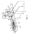
- Fig. 1 shows a device 10 for winding a pliable strand-like element (cable) 12, which in the present case is a cable.
- Cable 12 is fed by a feeder 16, which will be described in detail later, passes through two not yet engaged cable gripper jaws 32 and through the separator 30, is guided along a wall 14a on a flat surface 15 and takes on that surface is substantially U-shaped (forming a loop) before being fixed by a fixing device 18 at its free end.
- the feed device 16 has two circumferential belts 16a which are driven by a plurality of wheels 17. These wheels 17 contact each other and embed between them the belts 16a and between the belts 16a the cable 12 a. By the rotation of the wheels 17, the belts 16a revolve and guide the cable 12 due to friction with the belts 16a. At the exit end of the feeder 16 is another pair of wheels 17a, which pinch the cable 12 between them and can carry it on by a rotation of these wheels 17a.
- an open winding box 14 which consists of two pivotable about an axis 24 halves (parts) 20 and 22. At those ends of the winding box 14, which point away from the feeder 16, a spring-mounted cable gripper jaw 26 is provided on each part 20, 22.
- the winding device 14 has a recess 21 on each of its parts 20, 22 on each end surface. This recess 21 is in the folded state of the winding box 14 in the middle of the winding box when viewed along the axial direction. In each case two of these recesses 21 form an opening through which the cable 12 can enter or leave the winding box 14.
- the cable gripper jaws 26 serve to guide the cable 12, which passes through the winding box 14.
- the fixing device 18, which fixes the free end of the cable 12, is also formed of a pair of cable gripper jaws, which are engaged with each other and thereby clamp the cable 12.
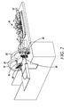
- Fig. 2 shows a further step for the controlled winding of the cable 12.
- the two parts 20, 22 of the winding box 14 are folded further than in Fig. 1 the case is.
- This condition is an intermediate step for completely enclosing the cable 12 through the winding box 14 and its cable gripper jaws 26.
- Fig. 3 shows the closed state, that is, the state in which the two parts 20, 22 of the winding box 14 the Surround cable 12, which now passes through the opening formed by recesses 21 in the box 14.
- the actual winding can begin, that is, the take-up is, so to speak, "ready to start”.
- FIG. 5 Such a condition is in Fig. 5 shown where already enough cable 12 has been introduced, which have formed several turns along the inner surface of the cable winding box.
- the winding box 14 is closed. Now that part of the cable 12 to which the feeder cable 12 has been supplied is fixed by a further cable gripper clamp 32, so that now its position is also defined. Subsequently, the cable 14 is severed by means of the severing device 30 between the feeder 16 and the further cable gripper terminal 32. In the present case, blades are pressed against the cable 14 from above and from below, whereby it is severed.
Landscapes
- Basic Packing Technique (AREA)
- Storing, Repeated Paying-Out, And Re-Storing Of Elongated Articles (AREA)
Priority Applications (1)
| Application Number | Priority Date | Filing Date | Title |
|---|---|---|---|
| EP14193407.5A EP3020672B1 (fr) | 2014-11-17 | 2014-11-17 | Dispositif d'enroulement d'un élément en forme de tige et flexible et procédé correspondant |
Applications Claiming Priority (1)
| Application Number | Priority Date | Filing Date | Title |
|---|---|---|---|
| EP14193407.5A EP3020672B1 (fr) | 2014-11-17 | 2014-11-17 | Dispositif d'enroulement d'un élément en forme de tige et flexible et procédé correspondant |
Publications (2)
| Publication Number | Publication Date |
|---|---|
| EP3020672A1 true EP3020672A1 (fr) | 2016-05-18 |
| EP3020672B1 EP3020672B1 (fr) | 2020-08-05 |
Family
ID=51900785
Family Applications (1)
| Application Number | Title | Priority Date | Filing Date |
|---|---|---|---|
| EP14193407.5A Active EP3020672B1 (fr) | 2014-11-17 | 2014-11-17 | Dispositif d'enroulement d'un élément en forme de tige et flexible et procédé correspondant |
Country Status (1)
| Country | Link |
|---|---|
| EP (1) | EP3020672B1 (fr) |
Cited By (1)
| Publication number | Priority date | Publication date | Assignee | Title |
|---|---|---|---|---|
| CN114144373A (zh) * | 2019-04-15 | 2022-03-04 | 米克朗瑞士股份公司自动化布德利分公司 | 用于缠绕医疗管的设备 |
Citations (9)
| Publication number | Priority date | Publication date | Assignee | Title |
|---|---|---|---|---|
| DE4235007A1 (de) * | 1992-10-16 | 1994-04-21 | Fraunhofer Ges Forschung | Verfahren zum Wickeln und Vorrichtung zur Durchführung des Verfahrens |
| US5427327A (en) | 1993-09-27 | 1995-06-27 | At&T Corp. | Method and apparatus for capturing and positioning a cable |
| EP1251605A1 (fr) | 2001-04-10 | 2002-10-23 | Komax Holding Ag | Appareil et méthode pour l'insertion de bout de câble dans des boítiers de connecteurs |
| EP1452474A1 (fr) | 2003-02-27 | 2004-09-01 | Bernhard Schäfer Werkzeug- und Sondermaschinen GmbH | Procédé et dispositif pour la fabrication mécanique d'un enroulement de câble sans support |
| EP1387449B1 (fr) | 2002-07-22 | 2005-04-27 | komax Holding AG | Appareil et méthode pour enrouler des câbles |
| EP1998044A2 (fr) | 2007-06-01 | 2008-12-03 | Fujikoki Corporation | Soupape de commande pour compresseurs à capacité variable et son procédé de fabrication |
| DE202007013417U1 (de) | 2007-09-24 | 2009-02-12 | Schleuniger Holding Ag | Vorrichtung zur Herstellung langer, konfektionierter, elektrischer Leitungen in einem CrimpCenter |
| DE112008002501T5 (de) | 2007-09-24 | 2010-10-21 | Schleuniger Holding Ag | Verfahren und Vorrichtung zur Herstellung langer, konfektionierter, elektrischer Leitungen |
| DE102012215902A1 (de) | 2012-09-07 | 2014-03-13 | Lisa Dräxlmaier GmbH | Wickelvorrichtung |
-
2014
- 2014-11-17 EP EP14193407.5A patent/EP3020672B1/fr active Active
Patent Citations (9)
| Publication number | Priority date | Publication date | Assignee | Title |
|---|---|---|---|---|
| DE4235007A1 (de) * | 1992-10-16 | 1994-04-21 | Fraunhofer Ges Forschung | Verfahren zum Wickeln und Vorrichtung zur Durchführung des Verfahrens |
| US5427327A (en) | 1993-09-27 | 1995-06-27 | At&T Corp. | Method and apparatus for capturing and positioning a cable |
| EP1251605A1 (fr) | 2001-04-10 | 2002-10-23 | Komax Holding Ag | Appareil et méthode pour l'insertion de bout de câble dans des boítiers de connecteurs |
| EP1387449B1 (fr) | 2002-07-22 | 2005-04-27 | komax Holding AG | Appareil et méthode pour enrouler des câbles |
| EP1452474A1 (fr) | 2003-02-27 | 2004-09-01 | Bernhard Schäfer Werkzeug- und Sondermaschinen GmbH | Procédé et dispositif pour la fabrication mécanique d'un enroulement de câble sans support |
| EP1998044A2 (fr) | 2007-06-01 | 2008-12-03 | Fujikoki Corporation | Soupape de commande pour compresseurs à capacité variable et son procédé de fabrication |
| DE202007013417U1 (de) | 2007-09-24 | 2009-02-12 | Schleuniger Holding Ag | Vorrichtung zur Herstellung langer, konfektionierter, elektrischer Leitungen in einem CrimpCenter |
| DE112008002501T5 (de) | 2007-09-24 | 2010-10-21 | Schleuniger Holding Ag | Verfahren und Vorrichtung zur Herstellung langer, konfektionierter, elektrischer Leitungen |
| DE102012215902A1 (de) | 2012-09-07 | 2014-03-13 | Lisa Dräxlmaier GmbH | Wickelvorrichtung |
Cited By (2)
| Publication number | Priority date | Publication date | Assignee | Title |
|---|---|---|---|---|
| CN114144373A (zh) * | 2019-04-15 | 2022-03-04 | 米克朗瑞士股份公司自动化布德利分公司 | 用于缠绕医疗管的设备 |
| CN114144373B (zh) * | 2019-04-15 | 2023-10-31 | 米克朗瑞士股份公司自动化布德利分公司 | 用于缠绕医疗管的设备 |
Also Published As
| Publication number | Publication date |
|---|---|
| EP3020672B1 (fr) | 2020-08-05 |
Similar Documents
| Publication | Publication Date | Title |
|---|---|---|
| EP3301768B1 (fr) | Procédé et dispositif pour l'alignement d'extrémités de câble préparées d'un faisceau de câbles | |
| EP1032095A2 (fr) | Méthode et appareil pour usiner et tordre un paire de conducteurs | |
| EP3182421B1 (fr) | Torsadage de conduites individuelles | |
| EP0134965B1 (fr) | Procédé et appareil pour appliquer des dispositifs de connexions sur conducteurs électriques | |
| DE2549833A1 (de) | Verfahren und vorrichtung zur zufuehrung einer mehrzahl von draehten | |
| DE102007048963A1 (de) | Verfahren zum optimierten pneumatischen Verbinden von Fäden oder Garnen und zugehörige Vorrichtung | |
| EP3144257A1 (fr) | Procede de fonctionnement d'un poste de travail et poste de travail | |
| DE102015112660A1 (de) | Verfahren zum Absaugen eines Fadens von einer Spule und entsprechende Vorrichtung | |
| EP3735737A1 (fr) | Procédé et dispositif de fabrication de rotors et de stators, incluant la confection de fils de connexion | |
| DE102011015060B4 (de) | Vorrichtung und Verfahren zum Herstellen von Rundbürsten | |
| EP2028732A2 (fr) | Procédé et dispositif de production et de confection consécutive d'une section de câble sur son extrémité avant et arrière | |
| DE2750913A1 (de) | Verfahren und vorrichtung zum verbinden von textilfaeden | |
| EP3020672B1 (fr) | Dispositif d'enroulement d'un élément en forme de tige et flexible et procédé correspondant | |
| DE10308432A1 (de) | Verfahren und Vorrichtung zur maschinellen Herstellung von spulenlosen Kabelwickeln | |
| EP3020671B1 (fr) | Méthode et dispositif de collecte d'une conduite | |
| DE3342858A1 (de) | Druckluft-fadenspleissvorrichtung | |
| DE4235007C2 (de) | Vorrichtung zum Wickeln und Abbinden von Kabeln, Litzen oder dgl. Wickelmaterial | |
| DE1560024A1 (de) | Verfahren und Vorrichtung zum Aufwickeln von Gespinsten | |
| DE102015110755A1 (de) | Vorrichtung und Verfahren zum Zwischenlagern von Leitungen | |
| EP0161573B1 (fr) | Procédé et dispositif pour enrouler des bobines enroulées, en particulier bobines de champ de machines électriques | |
| DE10126631A1 (de) | Verfahren und Vorrichtung zum Herstellen einer Bürste | |
| DE102019213325A1 (de) | Montagekopf sowie Verfahren zur automatisierten Umwicklung eines Leitungsstrangs | |
| DE2804542B1 (de) | Verfahren und Vorrichtung zum Herstellen eines Umwindegarnes | |
| DE19548735C2 (de) | Vorrichtung zum Bündeln und Binden von Balken oder Stäben | |
| DE102019001435A1 (de) | Verfahren und Vorrichtung zum Austausch von Fadenspulen einer Flechtmaschine |
Legal Events
| Date | Code | Title | Description |
|---|---|---|---|
| PUAI | Public reference made under article 153(3) epc to a published international application that has entered the european phase |
Free format text: ORIGINAL CODE: 0009012 |
|
| AK | Designated contracting states |
Kind code of ref document: A1 Designated state(s): AL AT BE BG CH CY CZ DE DK EE ES FI FR GB GR HR HU IE IS IT LI LT LU LV MC MK MT NL NO PL PT RO RS SE SI SK SM TR |
|
| AX | Request for extension of the european patent |
Extension state: BA ME |
|
| STAA | Information on the status of an ep patent application or granted ep patent |
Free format text: STATUS: REQUEST FOR EXAMINATION WAS MADE |
|
| 17P | Request for examination filed |
Effective date: 20161102 |
|
| RBV | Designated contracting states (corrected) |
Designated state(s): AL AT BE BG CH CY CZ DE DK EE ES FI FR GB GR HR HU IE IS IT LI LT LU LV MC MK MT NL NO PL PT RO RS SE SI SK SM TR |
|
| STAA | Information on the status of an ep patent application or granted ep patent |
Free format text: STATUS: EXAMINATION IS IN PROGRESS |
|
| 17Q | First examination report despatched |
Effective date: 20180913 |
|
| GRAP | Despatch of communication of intention to grant a patent |
Free format text: ORIGINAL CODE: EPIDOSNIGR1 |
|
| STAA | Information on the status of an ep patent application or granted ep patent |
Free format text: STATUS: GRANT OF PATENT IS INTENDED |
|
| INTG | Intention to grant announced |
Effective date: 20200309 |
|
| GRAS | Grant fee paid |
Free format text: ORIGINAL CODE: EPIDOSNIGR3 |
|
| GRAA | (expected) grant |
Free format text: ORIGINAL CODE: 0009210 |
|
| STAA | Information on the status of an ep patent application or granted ep patent |
Free format text: STATUS: THE PATENT HAS BEEN GRANTED |
|
| AK | Designated contracting states |
Kind code of ref document: B1 Designated state(s): AL AT BE BG CH CY CZ DE DK EE ES FI FR GB GR HR HU IE IS IT LI LT LU LV MC MK MT NL NO PL PT RO RS SE SI SK SM TR |
|
| REG | Reference to a national code |
Ref country code: GB Ref legal event code: FG4D Free format text: NOT ENGLISH |
|
| REG | Reference to a national code |
Ref country code: CH Ref legal event code: EP |
|
| REG | Reference to a national code |
Ref country code: AT Ref legal event code: REF Ref document number: 1298444 Country of ref document: AT Kind code of ref document: T Effective date: 20200815 |
|
| REG | Reference to a national code |
Ref country code: DE Ref legal event code: R096 Ref document number: 502014014556 Country of ref document: DE |
|
| REG | Reference to a national code |
Ref country code: IE Ref legal event code: FG4D Free format text: LANGUAGE OF EP DOCUMENT: GERMAN |
|
| REG | Reference to a national code |
Ref country code: LT Ref legal event code: MG4D |
|
| REG | Reference to a national code |
Ref country code: NL Ref legal event code: MP Effective date: 20200805 |
|
| PG25 | Lapsed in a contracting state [announced via postgrant information from national office to epo] |
Ref country code: BG Free format text: LAPSE BECAUSE OF FAILURE TO SUBMIT A TRANSLATION OF THE DESCRIPTION OR TO PAY THE FEE WITHIN THE PRESCRIBED TIME-LIMIT Effective date: 20201105 Ref country code: SE Free format text: LAPSE BECAUSE OF FAILURE TO SUBMIT A TRANSLATION OF THE DESCRIPTION OR TO PAY THE FEE WITHIN THE PRESCRIBED TIME-LIMIT Effective date: 20200805 Ref country code: FI Free format text: LAPSE BECAUSE OF FAILURE TO SUBMIT A TRANSLATION OF THE DESCRIPTION OR TO PAY THE FEE WITHIN THE PRESCRIBED TIME-LIMIT Effective date: 20200805 Ref country code: GR Free format text: LAPSE BECAUSE OF FAILURE TO SUBMIT A TRANSLATION OF THE DESCRIPTION OR TO PAY THE FEE WITHIN THE PRESCRIBED TIME-LIMIT Effective date: 20201106 Ref country code: NO Free format text: LAPSE BECAUSE OF FAILURE TO SUBMIT A TRANSLATION OF THE DESCRIPTION OR TO PAY THE FEE WITHIN THE PRESCRIBED TIME-LIMIT Effective date: 20201105 Ref country code: PT Free format text: LAPSE BECAUSE OF FAILURE TO SUBMIT A TRANSLATION OF THE DESCRIPTION OR TO PAY THE FEE WITHIN THE PRESCRIBED TIME-LIMIT Effective date: 20201207 Ref country code: LT Free format text: LAPSE BECAUSE OF FAILURE TO SUBMIT A TRANSLATION OF THE DESCRIPTION OR TO PAY THE FEE WITHIN THE PRESCRIBED TIME-LIMIT Effective date: 20200805 Ref country code: ES Free format text: LAPSE BECAUSE OF FAILURE TO SUBMIT A TRANSLATION OF THE DESCRIPTION OR TO PAY THE FEE WITHIN THE PRESCRIBED TIME-LIMIT Effective date: 20200805 Ref country code: HR Free format text: LAPSE BECAUSE OF FAILURE TO SUBMIT A TRANSLATION OF THE DESCRIPTION OR TO PAY THE FEE WITHIN THE PRESCRIBED TIME-LIMIT Effective date: 20200805 |
|
| PG25 | Lapsed in a contracting state [announced via postgrant information from national office to epo] |
Ref country code: LV Free format text: LAPSE BECAUSE OF FAILURE TO SUBMIT A TRANSLATION OF THE DESCRIPTION OR TO PAY THE FEE WITHIN THE PRESCRIBED TIME-LIMIT Effective date: 20200805 Ref country code: NL Free format text: LAPSE BECAUSE OF FAILURE TO SUBMIT A TRANSLATION OF THE DESCRIPTION OR TO PAY THE FEE WITHIN THE PRESCRIBED TIME-LIMIT Effective date: 20200805 Ref country code: PL Free format text: LAPSE BECAUSE OF FAILURE TO SUBMIT A TRANSLATION OF THE DESCRIPTION OR TO PAY THE FEE WITHIN THE PRESCRIBED TIME-LIMIT Effective date: 20200805 Ref country code: RS Free format text: LAPSE BECAUSE OF FAILURE TO SUBMIT A TRANSLATION OF THE DESCRIPTION OR TO PAY THE FEE WITHIN THE PRESCRIBED TIME-LIMIT Effective date: 20200805 Ref country code: IS Free format text: LAPSE BECAUSE OF FAILURE TO SUBMIT A TRANSLATION OF THE DESCRIPTION OR TO PAY THE FEE WITHIN THE PRESCRIBED TIME-LIMIT Effective date: 20201205 |
|
| PG25 | Lapsed in a contracting state [announced via postgrant information from national office to epo] |
Ref country code: CZ Free format text: LAPSE BECAUSE OF FAILURE TO SUBMIT A TRANSLATION OF THE DESCRIPTION OR TO PAY THE FEE WITHIN THE PRESCRIBED TIME-LIMIT Effective date: 20200805 Ref country code: DK Free format text: LAPSE BECAUSE OF FAILURE TO SUBMIT A TRANSLATION OF THE DESCRIPTION OR TO PAY THE FEE WITHIN THE PRESCRIBED TIME-LIMIT Effective date: 20200805 Ref country code: EE Free format text: LAPSE BECAUSE OF FAILURE TO SUBMIT A TRANSLATION OF THE DESCRIPTION OR TO PAY THE FEE WITHIN THE PRESCRIBED TIME-LIMIT Effective date: 20200805 Ref country code: RO Free format text: LAPSE BECAUSE OF FAILURE TO SUBMIT A TRANSLATION OF THE DESCRIPTION OR TO PAY THE FEE WITHIN THE PRESCRIBED TIME-LIMIT Effective date: 20200805 Ref country code: SM Free format text: LAPSE BECAUSE OF FAILURE TO SUBMIT A TRANSLATION OF THE DESCRIPTION OR TO PAY THE FEE WITHIN THE PRESCRIBED TIME-LIMIT Effective date: 20200805 |
|
| REG | Reference to a national code |
Ref country code: DE Ref legal event code: R097 Ref document number: 502014014556 Country of ref document: DE |
|
| PG25 | Lapsed in a contracting state [announced via postgrant information from national office to epo] |
Ref country code: AL Free format text: LAPSE BECAUSE OF FAILURE TO SUBMIT A TRANSLATION OF THE DESCRIPTION OR TO PAY THE FEE WITHIN THE PRESCRIBED TIME-LIMIT Effective date: 20200805 |
|
| PLBE | No opposition filed within time limit |
Free format text: ORIGINAL CODE: 0009261 |
|
| STAA | Information on the status of an ep patent application or granted ep patent |
Free format text: STATUS: NO OPPOSITION FILED WITHIN TIME LIMIT |
|
| PG25 | Lapsed in a contracting state [announced via postgrant information from national office to epo] |
Ref country code: MC Free format text: LAPSE BECAUSE OF FAILURE TO SUBMIT A TRANSLATION OF THE DESCRIPTION OR TO PAY THE FEE WITHIN THE PRESCRIBED TIME-LIMIT Effective date: 20200805 Ref country code: SK Free format text: LAPSE BECAUSE OF FAILURE TO SUBMIT A TRANSLATION OF THE DESCRIPTION OR TO PAY THE FEE WITHIN THE PRESCRIBED TIME-LIMIT Effective date: 20200805 |
|
| REG | Reference to a national code |
Ref country code: CH Ref legal event code: PL |
|
| 26N | No opposition filed |
Effective date: 20210507 |
|
| PG25 | Lapsed in a contracting state [announced via postgrant information from national office to epo] |
Ref country code: IT Free format text: LAPSE BECAUSE OF FAILURE TO SUBMIT A TRANSLATION OF THE DESCRIPTION OR TO PAY THE FEE WITHIN THE PRESCRIBED TIME-LIMIT Effective date: 20200805 Ref country code: LU Free format text: LAPSE BECAUSE OF NON-PAYMENT OF DUE FEES Effective date: 20201117 |
|
| REG | Reference to a national code |
Ref country code: BE Ref legal event code: MM Effective date: 20201130 |
|
| PG25 | Lapsed in a contracting state [announced via postgrant information from national office to epo] |
Ref country code: CH Free format text: LAPSE BECAUSE OF NON-PAYMENT OF DUE FEES Effective date: 20201130 Ref country code: SI Free format text: LAPSE BECAUSE OF FAILURE TO SUBMIT A TRANSLATION OF THE DESCRIPTION OR TO PAY THE FEE WITHIN THE PRESCRIBED TIME-LIMIT Effective date: 20200805 Ref country code: LI Free format text: LAPSE BECAUSE OF NON-PAYMENT OF DUE FEES Effective date: 20201130 |
|
| PG25 | Lapsed in a contracting state [announced via postgrant information from national office to epo] |
Ref country code: IE Free format text: LAPSE BECAUSE OF NON-PAYMENT OF DUE FEES Effective date: 20201117 |
|
| REG | Reference to a national code |
Ref country code: AT Ref legal event code: MM01 Ref document number: 1298444 Country of ref document: AT Kind code of ref document: T Effective date: 20201117 |
|
| PG25 | Lapsed in a contracting state [announced via postgrant information from national office to epo] |
Ref country code: AT Free format text: LAPSE BECAUSE OF NON-PAYMENT OF DUE FEES Effective date: 20201117 |
|
| PG25 | Lapsed in a contracting state [announced via postgrant information from national office to epo] |
Ref country code: TR Free format text: LAPSE BECAUSE OF FAILURE TO SUBMIT A TRANSLATION OF THE DESCRIPTION OR TO PAY THE FEE WITHIN THE PRESCRIBED TIME-LIMIT Effective date: 20200805 Ref country code: MT Free format text: LAPSE BECAUSE OF FAILURE TO SUBMIT A TRANSLATION OF THE DESCRIPTION OR TO PAY THE FEE WITHIN THE PRESCRIBED TIME-LIMIT Effective date: 20200805 Ref country code: CY Free format text: LAPSE BECAUSE OF FAILURE TO SUBMIT A TRANSLATION OF THE DESCRIPTION OR TO PAY THE FEE WITHIN THE PRESCRIBED TIME-LIMIT Effective date: 20200805 |
|
| PG25 | Lapsed in a contracting state [announced via postgrant information from national office to epo] |
Ref country code: MK Free format text: LAPSE BECAUSE OF FAILURE TO SUBMIT A TRANSLATION OF THE DESCRIPTION OR TO PAY THE FEE WITHIN THE PRESCRIBED TIME-LIMIT Effective date: 20200805 |
|
| PG25 | Lapsed in a contracting state [announced via postgrant information from national office to epo] |
Ref country code: BE Free format text: LAPSE BECAUSE OF NON-PAYMENT OF DUE FEES Effective date: 20201130 |
|
| PGFP | Annual fee paid to national office [announced via postgrant information from national office to epo] |
Ref country code: GB Payment date: 20230928 Year of fee payment: 10 |
|
| P01 | Opt-out of the competence of the unified patent court (upc) registered |
Effective date: 20231017 |
|
| PGFP | Annual fee paid to national office [announced via postgrant information from national office to epo] |
Ref country code: FR Payment date: 20230911 Year of fee payment: 10 |
|
| PGFP | Annual fee paid to national office [announced via postgrant information from national office to epo] |
Ref country code: DE Payment date: 20231129 Year of fee payment: 10 |