EP3019742B1 - Vertical axis wind turbine - Google Patents
Vertical axis wind turbine Download PDFInfo
- Publication number
- EP3019742B1 EP3019742B1 EP14789370.5A EP14789370A EP3019742B1 EP 3019742 B1 EP3019742 B1 EP 3019742B1 EP 14789370 A EP14789370 A EP 14789370A EP 3019742 B1 EP3019742 B1 EP 3019742B1
- Authority
- EP
- European Patent Office
- Prior art keywords
- air flow
- walls
- wall
- opening
- casing structure
- Prior art date
- Legal status (The legal status is an assumption and is not a legal conclusion. Google has not performed a legal analysis and makes no representation as to the accuracy of the status listed.)
- Not-in-force
Links
- 238000000926 separation method Methods 0.000 claims description 12
- 238000009434 installation Methods 0.000 description 7
- 238000004519 manufacturing process Methods 0.000 description 4
- 230000000694 effects Effects 0.000 description 3
- 230000001052 transient effect Effects 0.000 description 3
- 238000005452 bending Methods 0.000 description 2
- 238000010248 power generation Methods 0.000 description 2
- 230000006978 adaptation Effects 0.000 description 1
- 239000012634 fragment Substances 0.000 description 1
- 238000012423 maintenance Methods 0.000 description 1
- 239000000463 material Substances 0.000 description 1
- 238000012986 modification Methods 0.000 description 1
- 230000004048 modification Effects 0.000 description 1
- 230000003068 static effect Effects 0.000 description 1
- 230000000007 visual effect Effects 0.000 description 1
Images


Classifications
-
- F—MECHANICAL ENGINEERING; LIGHTING; HEATING; WEAPONS; BLASTING
- F03—MACHINES OR ENGINES FOR LIQUIDS; WIND, SPRING, OR WEIGHT MOTORS; PRODUCING MECHANICAL POWER OR A REACTIVE PROPULSIVE THRUST, NOT OTHERWISE PROVIDED FOR
- F03D—WIND MOTORS
- F03D3/00—Wind motors with rotation axis substantially perpendicular to the air flow entering the rotor
- F03D3/02—Wind motors with rotation axis substantially perpendicular to the air flow entering the rotor having a plurality of rotors
-
- F—MECHANICAL ENGINEERING; LIGHTING; HEATING; WEAPONS; BLASTING
- F03—MACHINES OR ENGINES FOR LIQUIDS; WIND, SPRING, OR WEIGHT MOTORS; PRODUCING MECHANICAL POWER OR A REACTIVE PROPULSIVE THRUST, NOT OTHERWISE PROVIDED FOR
- F03D—WIND MOTORS
- F03D3/00—Wind motors with rotation axis substantially perpendicular to the air flow entering the rotor
- F03D3/005—Wind motors with rotation axis substantially perpendicular to the air flow entering the rotor the axis being vertical
-
- F—MECHANICAL ENGINEERING; LIGHTING; HEATING; WEAPONS; BLASTING
- F03—MACHINES OR ENGINES FOR LIQUIDS; WIND, SPRING, OR WEIGHT MOTORS; PRODUCING MECHANICAL POWER OR A REACTIVE PROPULSIVE THRUST, NOT OTHERWISE PROVIDED FOR
- F03D—WIND MOTORS
- F03D3/00—Wind motors with rotation axis substantially perpendicular to the air flow entering the rotor
- F03D3/04—Wind motors with rotation axis substantially perpendicular to the air flow entering the rotor having stationary wind-guiding means, e.g. with shrouds or channels
- F03D3/0409—Wind motors with rotation axis substantially perpendicular to the air flow entering the rotor having stationary wind-guiding means, e.g. with shrouds or channels surrounding the rotor
-
- F—MECHANICAL ENGINEERING; LIGHTING; HEATING; WEAPONS; BLASTING
- F03—MACHINES OR ENGINES FOR LIQUIDS; WIND, SPRING, OR WEIGHT MOTORS; PRODUCING MECHANICAL POWER OR A REACTIVE PROPULSIVE THRUST, NOT OTHERWISE PROVIDED FOR
- F03D—WIND MOTORS
- F03D3/00—Wind motors with rotation axis substantially perpendicular to the air flow entering the rotor
- F03D3/04—Wind motors with rotation axis substantially perpendicular to the air flow entering the rotor having stationary wind-guiding means, e.g. with shrouds or channels
- F03D3/0436—Wind motors with rotation axis substantially perpendicular to the air flow entering the rotor having stationary wind-guiding means, e.g. with shrouds or channels for shielding one side of the rotor
- F03D3/0445—Wind motors with rotation axis substantially perpendicular to the air flow entering the rotor having stationary wind-guiding means, e.g. with shrouds or channels for shielding one side of the rotor the shield being fixed with respect to the wind motor
- F03D3/0454—Wind motors with rotation axis substantially perpendicular to the air flow entering the rotor having stationary wind-guiding means, e.g. with shrouds or channels for shielding one side of the rotor the shield being fixed with respect to the wind motor and only with concentrating action, i.e. only increasing the airflow speed into the rotor, e.g. divergent outlets
-
- F—MECHANICAL ENGINEERING; LIGHTING; HEATING; WEAPONS; BLASTING
- F03—MACHINES OR ENGINES FOR LIQUIDS; WIND, SPRING, OR WEIGHT MOTORS; PRODUCING MECHANICAL POWER OR A REACTIVE PROPULSIVE THRUST, NOT OTHERWISE PROVIDED FOR
- F03D—WIND MOTORS
- F03D3/00—Wind motors with rotation axis substantially perpendicular to the air flow entering the rotor
- F03D3/06—Rotors
- F03D3/062—Rotors characterised by their construction elements
-
- F—MECHANICAL ENGINEERING; LIGHTING; HEATING; WEAPONS; BLASTING
- F05—INDEXING SCHEMES RELATING TO ENGINES OR PUMPS IN VARIOUS SUBCLASSES OF CLASSES F01-F04
- F05B—INDEXING SCHEME RELATING TO WIND, SPRING, WEIGHT, INERTIA OR LIKE MOTORS, TO MACHINES OR ENGINES FOR LIQUIDS COVERED BY SUBCLASSES F03B, F03D AND F03G
- F05B2240/00—Components
- F05B2240/40—Use of a multiplicity of similar components
-
- Y—GENERAL TAGGING OF NEW TECHNOLOGICAL DEVELOPMENTS; GENERAL TAGGING OF CROSS-SECTIONAL TECHNOLOGIES SPANNING OVER SEVERAL SECTIONS OF THE IPC; TECHNICAL SUBJECTS COVERED BY FORMER USPC CROSS-REFERENCE ART COLLECTIONS [XRACs] AND DIGESTS
- Y02—TECHNOLOGIES OR APPLICATIONS FOR MITIGATION OR ADAPTATION AGAINST CLIMATE CHANGE
- Y02B—CLIMATE CHANGE MITIGATION TECHNOLOGIES RELATED TO BUILDINGS, e.g. HOUSING, HOUSE APPLIANCES OR RELATED END-USER APPLICATIONS
- Y02B10/00—Integration of renewable energy sources in buildings
- Y02B10/30—Wind power
-
- Y—GENERAL TAGGING OF NEW TECHNOLOGICAL DEVELOPMENTS; GENERAL TAGGING OF CROSS-SECTIONAL TECHNOLOGIES SPANNING OVER SEVERAL SECTIONS OF THE IPC; TECHNICAL SUBJECTS COVERED BY FORMER USPC CROSS-REFERENCE ART COLLECTIONS [XRACs] AND DIGESTS
- Y02—TECHNOLOGIES OR APPLICATIONS FOR MITIGATION OR ADAPTATION AGAINST CLIMATE CHANGE
- Y02E—REDUCTION OF GREENHOUSE GAS [GHG] EMISSIONS, RELATED TO ENERGY GENERATION, TRANSMISSION OR DISTRIBUTION
- Y02E10/00—Energy generation through renewable energy sources
- Y02E10/70—Wind energy
- Y02E10/74—Wind turbines with rotation axis perpendicular to the wind direction
Definitions
- the present invention relates to the field of wind turbines.
- the invention relates to the field of vertical axis wind turbines with outer casing structure, or case.
- Wind turbines can be subdivided into two large categories depending on the rotor direction: horizontal axis turbines and vertical axis turbines.
- An example of horizontal axis turbines are the windmills, where the rotation axis of the rotor is arranged substantially aligned with the prevailing air flow direction.
- the rotation axis can rotate in turn, usually about a vertical axis, in order to achieve and/or keep the alignment of the rotation axis of the rotor with the prevailing air flow direction of.
- all the blades are invested at the same time by air flow and all the blades take part positively to the rotation of the rotor.
- Horizontal axis turbines have the drawbacks of requiring much space for installation and of being characterized by a high mechanical complexity. These drawbacks cause a high production and installation costs, besides having a big visual impact on the landscape, once installed.
- Vertical axis turbines are characterized by a reduced mechanical complexity (with respect to horizontal axis turbines) because, for example, they are not necessarily devices that perform and/or maintain the alignment between the rotor axis and the prevailing air flow direction. Such feature explains why this type of machines has both a production cost and a maintenance cost that lower than horizontal axis machines.
- a first solution provided by documents like US5852331A , JP2005299621A and WO2011/086406A2 , is that of shielding the "resistant path" to avoid that the air flow can act on the blade, reducing the overall efficiency.
- a further solution consists of improving the feeding efficiency of the rotor, by directing the air flow towards the outer diameter of the rotor.
- a possible solution to the problem of directing the turbine in the air flow direction is disclosed, for example, in DE29980074U1 and US2011/291421A1 , in which an outer case enclosing rotor and blades is provided.
- the outer case is furthermore equipped with a plurality of openings that operate both as inlet and outlet of the flow, according to the wind direction, and that convey air flow to the blades.
- a vertical axis wind turbine comprising:
- each wall is defined by a respective edge arranged to connect a vertex V 1 ,...,V n of the first plurality with a corresponding vertex V 1 ',...,V n ' of the second plurality.
- each edge has a profile protruding outwards from the casing structure, said protruding profile arranged to protrude beyond a corresponding straight line V 1 -V 1 ',...,V n -V n ' connecting the vertex V 1 ,...,V n of the first plurality with the corresponding vertex V 1 ',...,V n ' of the second plurality.
- an entering air flow which enters the casing structure through a first opening, can slide on the adjacent wall, which works as a convergent duct.
- the edge protruding outwards from such wall increases the resistance opposed to the air flow and deviates the air flow that does not enter the casing structure, so that, for most wind directions, this air flow is detached from the above described wall, creating, at a second opening, adjacent to the wall opposite to the first opening, which works as outlet for an exiting air flow, a low-pressure zone that increases the flow rate of the entering air flow that enters casing structure, increasing then the wind power exploited by the turbine.
- the low-pressure at second opening allows the turbine, when starting, to operate for speeds of entering air flow lower than in turbines of prior art.
- low-pressure at second opening generated by the presence of protruding edge, allows both to start more easily the turbine when the air flow is in transient state, both to increase the power when air flow is in steady state.
- the edge protruding outwards has curvilinear geometry with concavity oriented towards a respective opening, in order to act as the opening of a duct arranged to direct the air flow entering the casing structure.
- the protruding edge has a shape of circular arc of predetermined radius.
- At least one wall of the plurality of walls has a protruding portion, which starts from said edge, and configured in such a way that its projection in the plane of the lower plate is external to an ideal polygon joining the vertices V 1 ,...,V n of the lower plate to one another.
- the wall also comprises also a recessed portion whose projection in the plane of the lower plate is internal to the polygon, said recessed portion extending up to an opening adjacent to the wall, beyond an end of the wall opposite to the edge.
- the edge of the wall has a thickness higher than the remaining part of the wall.
- the lower plate is defined by profiles that connect two by two the vertices V 1 ,...,V n and that are recessed towards the rotation axis z with respect to said polygon, in order to adapt to recessed portions of the walls.
- the upper plate is defined by profiles that connect two by two the vertices V 1 ',...,V n ' and that are recessed towards the rotation axis z with respect to said polygon, in order to adapt to recessed portions of the walls.
- the air flow that slides outside on the walls does not meet the surface of the plates that would interfere with the motion of the flow, and would also increase friction drag and loose energy.
- the profile that defines the two plates has a point of maximum M, i.e. a point where there is the greatest distance between the profile and the corresponding edge of the polygon which connects the vertices V 1 ,...,V n or the vertices V 1 ',...,V n '.
- This point of maximum M is located near the above described end of the walls.
- Each wall then maintains a substantially constant inclination from the edge to the end, beyond which the wall breaks, thus leaving space to the adjacent opening. This way, each wall, in addition to work as obstacle for creating the low-pressure at the outlet, works also as convergent duct for the air flow that enters the casing structure.
- each profile that joins two plates has a tangent line between 0° and 30° with respect to a corresponding edge of an ideal polygon that connects the vertices V 1 ,...,V n , to the farthest vertex from recessed portion of the wall.
- the profile meets the inclination of the wall, which works as convergent duct with inclination of 30°.
- each profile joining the plates comprises, at the corresponding opening, a straight portion which is used to strengthen the structure, giving to the wall a stiffening effect that prevents it from bending when it is subjected to heavy aerodynamic loads.
- ribs with substantially reticular geometry are provided, that, in addition to assist the structural resistance of the walls, further assist the separation of the air flow, and, in particular of the boundary layer, from the walls.
- the casing structure comprises four walls, which are of identical shape and are at an angle of 90° from each other about axis z, which define four openings configured to work as inlet/outlet for the air flow in/from the casing structure.
- Such configuration is aerodynamically optimal and allows an efficiency that is much less variable responsive to changes of the wind direction. Furthermore, by having identical components, it reduces the production costs and assists the assembly of the turbine.
- a first opening among the four openings is configured to allow a main air flow component to enter, said first opening being adjacent to a first wall of the four walls and to a second wall of the four walls, substantially orthogonal to the first wall.
- the low-pressure zone at the second opening allows both to start more easily the turbine when the air flow is in transient state, both to increase the power when air flow is in steady state.
- the low-pressure zone at the fourth opening contributes to cause the air flow to exit from the casing structure, through the fourth opening, allowing emptying the "resistant path" of the rotor and thus reducing the resistance encountered by the rotor in its rotation.
- Such lower resistance causes an improvement of the overall efficiency of the wind turbine, allowing to further lower the value of the wind speed for which the turbine comes into operation at start up.
- a system of wind energy generation comprises at least two wind turbines, according to the present invention, which are located above each other, in such a way that the rotation axes z of the wind turbines are coincident.
- This way it is possible to create systems of wind power generation that require a surface of installation substantially the same as the surface necessary to a single turbine.
- This allows to strongly optimize the space with respect to the systems of wind power generation of prior art, which usually provide the arrangement of several wind turbines in a triangle or in a square, thus needing a surface of installation much bigger than that required for a single turbine.
- such an arrangement in column does not affect the performance of the individual turbines with respect to each other.
- the wind turbines are rotationally shifted with respect to the rotation axis z of a predetermined angle from each other.
- the predetermined angular offset is set between 20° and 40°, advantageously, it is equal to 30°.
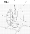
- an exemplary embodiment of a vertical axis wind turbine 100 comprises a rotor 110 ( Fig.1 ) and a casing structure 120 ( Fig.2 ) that houses the rotor 110.
- rotor 110 comprises a plurality of blades 111, in particular 3, which are arranged in an axial-symmetric way with respect to a vertical rotation axis z, about which the blades 111 are wheeled, as consequence of the aerodynamic drag opposed to an air flow that invest blades 111.
- casing structure 120 comprises a lower plate 121 and an upper plate 122, substantially orthogonal to the axis z, and defined, respectively, by a first plurality of vertices, in particular four vertices, V 1 , V 2 , V 3 , V 4 and a second plurality of vertices, in particular four vertices, V 1 ', V 2 ', V 3 ', V 4 '.
- the two plates 121 and 122 are connected to each other through a plurality of walls, in particular four walls, 125a-125d, which create, with the two plates 121,122, four openings 126a-126d that work, according to the direction of air flow that crosses the casing structure 120, as air flow inlet and/or outlet ports.
- the walls 125a-125d, as well as all the other side elements of the casing structure 120, are equal to each other and repeated for each one of four sides V 1 -V 2 , V 2 -V 3 , V 3 -V 4 , V 4 -V 1 .
- each of walls 125a-125d is defined by edges 127a-127d, each of which connects one of the vertices V 1 , V 2 , V 3 , V 4 with one of the corresponding vertices V 1 ', V 2 ', V 3 ', V 4 '.
- each edge 127a-127d is protruding outwards from the casing structure 120 with respect to the corresponding vertical line that connects one of the vertices V 1 , V 2 , V 3 , V 4 with one of the corresponding vertices V 1 ', V 2 ', V 3 ', V 4 '.
- an air flow that enters casing structure 120 through, for example, a first opening 126a slides on adjacent wall 125b, which works as convergent duct.
- the edge 127b protruding outwards from wall 125b, increases the resistance opposed to the air flow and deviates the air flow that does not enter casing structure 120, so that, for the majority of the wind directions, this air flow is separated by the wall 125b creating, at a second opening 126b, which is adjacent to the wall 125b and that works as outlet of the air flow, a low-pressure zone that increases the air flow rate that enters casing structure 120, increasing then the wind power exploited by the turbine 100.
- the low-pressure at the second opening 126b allows the turbine to operate for start up speeds of inlet air flow lower than turbines of prior art.
- the low-pressure at opening 126b generated by the presence of protruding edge 127b, allows both to assist the start up of turbine 100 when the air flow is in transient state, and to increase the power when the air flow is in steady state.
- wall 125a thanks to edge 127a, which is also protruding, opposes a resistance against the air flow that allows an immediate separation of such air flow, generating, in a similar way as above said, a low-pressure zone at a fourth opening 126d, which is also useful for the exit of the air flow from the casing structure 120.
- Such low-pressure zone on the fourth opening 126d contributes to cause the air flow to exit from the casing structure 120, through the opening 126d, allowing emptying the "resistant path" of the rotor 110 and then reducing the resistance encountered by the rotor 110 in its rotation.
- a lower resistance causes an improvement of the overall efficiency of the wind turbine 100, allowing further to lower the value of the wind speed for turbine 100 at the start up.
- the protruding edge 127b has a curvilinear shape, as a circular arc with concavity oriented towards the opening 126a, which allows the opening 126a to better convey the air flow entering the casing structure 120, assuming a shape similar to that of an inlet duct.
- the walls 125a-125d comprise a protruding portion 125a'-125d', configured in such a way that its projection in the plane of the lower plate 121 is external to the square, and a recessed portion 125a"-125d", whose projection in this plane instead remains inside the square itself.
- the protruding portion 125b' comprises edge 127b and, as said, is used for increasing the resistance opposed to the air flow, in order to allow the separation from wall 125b.
- the recessed portion 125b instead, causes the low-pressure generated by said flow separation to occur exactly at outlet 126b.
- this embodiment allows that the phenomenon above described occurs substantially for any direction of the wind, even for those parallel to a wall 125a-125d, which is the more critic direction, at which it is much more difficult the separation of the air flow.
- the edge 127a-127d may have a thickness greater than the rest of the wall 125a-125d, as shown in Figs. 2 and 3 .
- the plates 121 and 122 are joined by profiles 123a-123d and 123a'-123d' that connect two by two the vertices V 1 , V 2 , V 3 , V 4 and the vertices V 1 ', V 2 ', V 3 ', V 4 ', respectively.
- Such profiles 123a-123d and 123a'-123of are curvilinear and are recessing towards the rotation axis z, in order to meet the shape of the walls 125a-125d, and, in particular of recessing portions 125a"-125d". This way, an air flow that slides outside on walls 125a-125d does not encounter the surface of the plates that would interfere with the motion of the flow, and would also increase the friction drag and loose energy.
- profiles 123a-123d and 123a'-123d' substantially follow the trend of walls 125a-125d.
- profiles 123a-123d and 123a'-123d' have a point of maximum M, i.e. a point at which the distance between the profile and the side of said square is greatest.
- Such point of maximum M is located close to the recessed portion 125a"-125d", and, in particular at one end 127a'-127d' of the wall 125a-125d opposite to the edge 127a-127d.
- the wall 125b, and similarly the other walls 125a, 125c, 125d maintains an inclination substantially constant from edge 127a up to second edge 127a', beyond which the wall 125b is interrupted leaving space to the adjacent opening 126b.
- the wall 125b in addition to act as an obstacle to create the low-pressure at outlet 126b, acts also as convergent duct for the air flow that enters the casing structure.
- the wall 125b has an inclination of about 30° with respect to the segment V 1 '-V 2 ', or to the segment V 1 -V 2 .
- the profiles 123b and 123b' which must follow the wall 125b, have a tangent line at vertices V 1 and V 1 ' that is about 30°.
- profiles 123b and 123b' at the vertices V 2 and V 2 ' instead, is about 30° with respect to the segments V 2 -V 3 and V 2 '-V 3 ', in order to allow a wall 125c to be in turn a convergent duct with respect to the inlet 126b.
- profiles 123b and 123b' comprise, in the part adjacent to vertices V 2 and V 2 ', straight portions 124b and 124b' that serve to strengthen the structure, giving to the wall 125c a stiffening effect that prevents it from bending when it is subjected to large aerodynamic loads.
- ribs with substantially reticular geometry are provided on the outer surface of walls 125a-125d.
- Such stiffening ribs in addition to contribute to the structural strength of the walls 125a-125d, also contribute to further facilitate the separation of the air flow, and, in particular of the boundary layer, from the walls.
- the present invention provides a system of wind energy generation 200 comprising more than one wind turbine 100 as previously described.
- the turbines 100 are arranged above one another aligned with respect to vertical axis z. This way, systems of wind energy generation 200 can be obtained that require an installation surface substantially the same as the surface necessary to a single turbine 100.
- This allows to strongly optimize the space with respect to the systems of wind energy generation of the prior art, which usually provide the arrangement of multiple wind turbines in a triangle or in a square, thus requiring a surface of installation much bigger than a single turbine.
- this arrangement in column does not affect the performances of singles turbines 100.
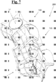
- an exemplary embodiment of the system of wind energy generation 200 provides that the wind turbines 100 are rotationally shifted at a predetermined angle about its axis z with respect to each other, in order to further increase, with respect to the single wind turbine 100 and to the system 100 of Fig. 6 , the invariance of the performances of the wind system 100 respect to the direction of the wind.
- Such predetermined angle is advantageously set between 20° and 40°, and in particular 30°.
- the optimal value of this angle can result different depending on the number of wind turbines 100 arranged in column.
- the arrangement of the turbines 100 of Fig. 7 distributes in a more balanced way the aerodynamic loads, especially fatigue loads, which the system 100 must endure, reducing the possibility of resonance phenomena and allowing a higher life of the components.
Landscapes
- Engineering & Computer Science (AREA)
- Life Sciences & Earth Sciences (AREA)
- Sustainable Development (AREA)
- Sustainable Energy (AREA)
- Chemical & Material Sciences (AREA)
- Combustion & Propulsion (AREA)
- Mechanical Engineering (AREA)
- General Engineering & Computer Science (AREA)
- Wind Motors (AREA)
Applications Claiming Priority (2)
| Application Number | Priority Date | Filing Date | Title |
|---|---|---|---|
| IT000067A ITPI20130067A1 (it) | 2013-07-12 | 2013-07-12 | Turbina eolica ad asse verticale |
| PCT/IB2014/062913 WO2015004588A1 (en) | 2013-07-12 | 2014-07-07 | Vertical axis wind turbine |
Publications (2)
| Publication Number | Publication Date |
|---|---|
| EP3019742A1 EP3019742A1 (en) | 2016-05-18 |
| EP3019742B1 true EP3019742B1 (en) | 2017-06-21 |
Family
ID=49182392
Family Applications (1)
| Application Number | Title | Priority Date | Filing Date |
|---|---|---|---|
| EP14789370.5A Not-in-force EP3019742B1 (en) | 2013-07-12 | 2014-07-07 | Vertical axis wind turbine |
Country Status (10)
| Country | Link |
|---|---|
| US (1) | US20160169196A1 (enExample) |
| EP (1) | EP3019742B1 (enExample) |
| JP (1) | JP2016524094A (enExample) |
| CN (1) | CN105980702A (enExample) |
| AU (1) | AU2014288898B2 (enExample) |
| CA (1) | CA2918116A1 (enExample) |
| IT (1) | ITPI20130067A1 (enExample) |
| RU (1) | RU2016101648A (enExample) |
| WO (1) | WO2015004588A1 (enExample) |
| ZA (1) | ZA201600419B (enExample) |
Cited By (1)
| Publication number | Priority date | Publication date | Assignee | Title |
|---|---|---|---|---|
| RU2688095C1 (ru) * | 2018-05-30 | 2019-05-17 | Алексей Владимирович Рябов | Ветряная регулируемая установка с вертикальной осью вращения |
Families Citing this family (4)
| Publication number | Priority date | Publication date | Assignee | Title |
|---|---|---|---|---|
| MY193720A (en) * | 2015-06-24 | 2022-10-26 | Guy Andrew Vaz | A guide vane assembly |
| WO2018073729A1 (en) | 2016-10-18 | 2018-04-26 | Pellegri Adriano | Cyclonic-flow wind turbine with statoric and rotoric elements |
| CN107664095A (zh) * | 2017-11-14 | 2018-02-06 | 邹跃洲 | 螺旋型风力发电机叶片 |
| CL2018002529A1 (es) * | 2018-09-04 | 2019-01-18 | Orellana Olguin Nicolas Gonzalo | Aparato generador omnidireccional |
Family Cites Families (76)
| Publication number | Priority date | Publication date | Assignee | Title |
|---|---|---|---|---|
| US574411A (en) * | 1897-01-05 | Windmill | ||
| US294943A (en) * | 1884-03-11 | Windmill | ||
| US1100332A (en) * | 1912-09-03 | 1914-06-16 | James B Smith | Windmill. |
| US1466026A (en) * | 1922-02-24 | 1923-08-28 | Ebenezer H Manning | Wind turbine |
| US1697574A (en) * | 1924-12-12 | 1929-01-01 | Savonius Sigurd Johannes | Rotor adapted to be driven by wind or flowing water |
| US1619643A (en) * | 1925-09-14 | 1927-03-01 | Martin L Webb | Wind turbine |
| US3918839A (en) * | 1974-09-20 | 1975-11-11 | Us Energy | Wind turbine |
| WO1981003683A1 (fr) | 1980-06-10 | 1981-12-24 | Japan Wind Power Generator Co | Dispositif collecteur d'air a plaque pour moulin a vent a puits vertical |
| ES495343A0 (es) * | 1980-09-25 | 1981-08-01 | Martinez Parra Jose | Sistema de produccion de energia electrica,mediante el apro-vechamiento y control de la fuerza del viento |
| US4383801A (en) * | 1981-03-02 | 1983-05-17 | Pryor Dale H | Wind turbine with adjustable air foils |
| FR2541383A1 (fr) | 1982-03-16 | 1984-08-24 | Schweizer Otto | Turbine eolienne pouvant se placer dans differentes positions |
| US4486143A (en) * | 1982-09-01 | 1984-12-04 | Mcvey Paul W | Turbine-type wind machine |
| US4551631A (en) * | 1984-07-06 | 1985-11-05 | Trigilio Gaetano T | Wind and solar electric generating plant |
| US4718822A (en) * | 1986-09-25 | 1988-01-12 | Riezinstein And Malone Industries | Vertically oriented wind driven assembly |
| US5336933A (en) * | 1990-07-16 | 1994-08-09 | Bru-Mel Corporation | Fluid-augmented free-vortex power generating apparatus |
| US5252029A (en) * | 1991-09-13 | 1993-10-12 | Barnes Robert J | Vertical axis wind turbine |
| US5505416A (en) * | 1994-06-20 | 1996-04-09 | Dodge; John P. | Clamp for a pipe or a tube |
| US5852331A (en) * | 1996-06-21 | 1998-12-22 | Giorgini; Roberto | Wind turbine booster |
| DE19823473A1 (de) * | 1998-05-26 | 1999-12-02 | Gunter Kraus | Strömungsenergieanlage |
| US6448669B1 (en) * | 1998-12-01 | 2002-09-10 | Dillyn M. Elder | Water power generation system |
| US6345957B1 (en) * | 2000-07-17 | 2002-02-12 | Roman Szpur | Cavity vertical turbine |
| US6465899B2 (en) * | 2001-02-12 | 2002-10-15 | Gary D. Roberts | Omni-directional vertical-axis wind turbine |
| US7241105B1 (en) * | 2002-06-07 | 2007-07-10 | Vanderhye Robert A | Watercraft with vertically collapsible vertical axis wind turbine and propeller flexible drive shaft |
| WO2004011798A2 (en) * | 2002-07-31 | 2004-02-05 | The Board Of Trustees Of The University Of Illinois | Wind turbine device |
| US6808366B2 (en) * | 2002-09-11 | 2004-10-26 | Vertical Wind Turbine Technologies, LLC | Fluid flow powered dynamo with lobed rotors |
| GB2402976B (en) * | 2003-06-05 | 2006-09-27 | Intec Power Systems Ltd | Generator |
| GB2404227B (en) * | 2003-07-24 | 2006-02-01 | Xc02 Conisbee Ltd | Vertical-axis wind turbine |
| US7362004B2 (en) * | 2003-07-29 | 2008-04-22 | Becker William S | Wind turbine device |
| US7040859B2 (en) * | 2004-02-03 | 2006-05-09 | Vic Kane | Wind turbine |
| US7008171B1 (en) * | 2004-03-17 | 2006-03-07 | Circle Wind Corp. | Modified Savonius rotor |
| JP2005299621A (ja) * | 2004-04-08 | 2005-10-27 | Kazuhiro Kamakura | 風増速装置及びこれを用いた風力発電装置 |
| EP1825140A1 (en) * | 2004-10-20 | 2007-08-29 | Vortech Energy & Power Pty Limited | Vertical axis wind turbine with twisted blade or auxiliary blade |
| MX2007007730A (es) * | 2004-12-23 | 2007-08-16 | Katru Eco Inv S Pty Ltd | Turbina eolica omnidireccional. |
| US7762777B2 (en) * | 2005-01-12 | 2010-07-27 | Robert A. Vanderhye | Savonius wind turbine construction |
| US7344353B2 (en) * | 2005-05-13 | 2008-03-18 | Arrowind Corporation | Helical wind turbine |
| US7329965B2 (en) * | 2005-06-03 | 2008-02-12 | Novastron Corporation | Aerodynamic-hybrid vertical-axis wind turbine |
| WO2007027113A1 (en) * | 2005-09-02 | 2007-03-08 | Ballena Abraham E | Vertical axis wind turbine |
| US7287954B2 (en) * | 2005-09-30 | 2007-10-30 | California Energy & Power | Omni directional baffled wind energy power converter apparatus and method |
| US7288850B2 (en) * | 2005-12-29 | 2007-10-30 | Hicks Michael F | System and apparatus for emergency backup power generation |
| US8297930B2 (en) * | 2006-04-07 | 2012-10-30 | Windworks Engineering Limited | Vertical axis wind turbine |
| US7909567B2 (en) * | 2006-12-22 | 2011-03-22 | Genedics Clean Energy, Llc | Stratum deployment of wind turbines |
| US7726934B2 (en) * | 2007-02-06 | 2010-06-01 | Preferred Energy, L.L.C. | Vertical axis wind turbine |
| US8164210B2 (en) * | 2007-03-07 | 2012-04-24 | Boone Daniel N | Vertical axis wind turbine with angled braces |
| US8322992B2 (en) * | 2007-04-17 | 2012-12-04 | Adam Fuller | Modular wind-driven electrical power generator and method of manufacture |
| US7896608B2 (en) * | 2007-06-28 | 2011-03-01 | Circle Wind Corp. | Three-vaned drag-type wind turbine |
| ITNA20070103A1 (it) * | 2007-10-18 | 2009-04-19 | Oreste Caputi | Turbina a flussi incrociati |
| US8057159B2 (en) * | 2008-01-17 | 2011-11-15 | Chong Wun C | Twin wind turbine power system |
| WO2009109107A1 (zh) * | 2008-03-04 | 2009-09-11 | 南京宇能仪表有限公司 | 一种风力发电系统 |
| DE102008012587A1 (de) * | 2008-03-05 | 2009-09-10 | Gerd Eisenblätter Gmbh | Optimierter Rotor für eine Windkraftanlage und Windkraftanlage zur Montage auf einem Gebäude |
| US8100651B2 (en) * | 2008-06-24 | 2012-01-24 | Kuei-Sheng Tsou | Stabilizing apparatus for vertical axis wind turbine |
| US7744338B2 (en) * | 2008-09-04 | 2010-06-29 | California Energy & Power | Fluid turbine systems |
| US20120292912A1 (en) * | 2011-05-16 | 2012-11-22 | Median Wind, Llc | Wind power generation system and method |
| US20100194251A1 (en) * | 2009-02-02 | 2010-08-05 | Sikes George W | Axial generator for Windcrank™ vertical axis wind turbine |
| US8790068B2 (en) * | 2009-03-10 | 2014-07-29 | Larry Cantwell | Low wind, vertical axis, dual stage, wind turbine power generator |
| US20100233919A1 (en) * | 2009-03-12 | 2010-09-16 | Ersoy Seyhan | Check valve turbine |
| US8096750B2 (en) * | 2009-03-30 | 2012-01-17 | Ocean Renewable Power Company, Llc | High efficiency turbine and method of generating power |
| US8487470B2 (en) * | 2009-05-22 | 2013-07-16 | Derek Grassman | Vertical axis wind turbine and generator therefore |
| CN201486753U (zh) * | 2009-06-26 | 2010-05-26 | 北京希翼新兴能源科技有限公司 | 垂直轴复合式风轮机 |
| ITVA20090039A1 (it) * | 2009-06-29 | 2010-12-30 | Gabriele Biucchi | Dispositivo per la produzione di energia elettrica e termica da energia eolica e solare tramite turbina ad asse verticale |
| US8998562B2 (en) * | 2009-09-16 | 2015-04-07 | Horia Nica | Hollow rotor core for generating a vortex in a wind turbine |
| CN201865840U (zh) * | 2009-09-18 | 2011-06-15 | 北京希翼新兴能源科技有限公司 | 垂直轴风力发电机风叶及其风轮 |
| US8464990B2 (en) * | 2009-10-01 | 2013-06-18 | Idea Labs, Inc. | Pole mounted rotation platform and wind power generator |
| CA2774870A1 (en) * | 2009-10-13 | 2011-04-21 | Roberto Bolelli | Energy conversion assembly |
| US8456033B2 (en) * | 2009-12-17 | 2013-06-04 | Empire Magnetics Inc. | Antenna mounted wind power generator |
| ITSP20100001A1 (it) * | 2010-01-18 | 2011-07-19 | Treecube Srl | Turbina eolica ad asse verticale con rotore inserito in un convogliatore |
| US20110291421A1 (en) * | 2010-06-01 | 2011-12-01 | Fang Ming Tsung | Wind-Deflection Omni-Directional Vertical Wind-Driven Device |
| GB2484109A (en) * | 2010-09-29 | 2012-04-04 | Nenuphar | Vertical axis wind turbine having modular blades with support arm at joint |
| KR101217314B1 (ko) * | 2010-11-05 | 2012-12-31 | 강옥례 | 풍향조절 날개형 수직축 풍차 |
| US8864440B2 (en) * | 2010-11-15 | 2014-10-21 | Sauer Energy, Incc. | Wind sail turbine |
| DE102012203138A1 (de) * | 2012-02-29 | 2013-08-29 | Josef Moser | Rotor für vertikale Windkraftanlage |
| US9011096B2 (en) * | 2012-06-01 | 2015-04-21 | Max Su | Vertical axis wind turbine blade |
| US9103321B1 (en) * | 2012-09-13 | 2015-08-11 | Jaime Mlguel Bardia | On or off grid vertical axis wind turbine and self contained rapid deployment autonomous battlefield robot recharging and forward operating base horizontal axis wind turbine |
| US9284945B2 (en) * | 2013-03-15 | 2016-03-15 | Douglas Brendle | Wind turbine and tower system |
| US9714640B2 (en) * | 2013-04-30 | 2017-07-25 | Windpax Llc | Wind turbine apparatus |
| JP5963146B2 (ja) * | 2013-05-25 | 2016-08-03 | 吉二 玉津 | 風切羽開閉翼システムを用いた垂直軸式水風車原動機 |
| US10502182B2 (en) * | 2016-08-08 | 2019-12-10 | Moa'z Mahmoud Yusuf Elayyan | Wind turbine |
-
2013
- 2013-07-12 IT IT000067A patent/ITPI20130067A1/it unknown
-
2014
- 2014-07-07 AU AU2014288898A patent/AU2014288898B2/en not_active Ceased
- 2014-07-07 CA CA2918116A patent/CA2918116A1/en not_active Abandoned
- 2014-07-07 RU RU2016101648A patent/RU2016101648A/ru not_active Application Discontinuation
- 2014-07-07 CN CN201480038682.3A patent/CN105980702A/zh active Pending
- 2014-07-07 US US14/904,475 patent/US20160169196A1/en not_active Abandoned
- 2014-07-07 WO PCT/IB2014/062913 patent/WO2015004588A1/en not_active Ceased
- 2014-07-07 JP JP2016524926A patent/JP2016524094A/ja active Pending
- 2014-07-07 EP EP14789370.5A patent/EP3019742B1/en not_active Not-in-force
-
2016
- 2016-01-19 ZA ZA2016/00419A patent/ZA201600419B/en unknown
Cited By (1)
| Publication number | Priority date | Publication date | Assignee | Title |
|---|---|---|---|---|
| RU2688095C1 (ru) * | 2018-05-30 | 2019-05-17 | Алексей Владимирович Рябов | Ветряная регулируемая установка с вертикальной осью вращения |
Also Published As
| Publication number | Publication date |
|---|---|
| WO2015004588A1 (en) | 2015-01-15 |
| AU2014288898A1 (en) | 2016-02-04 |
| ITPI20130067A1 (it) | 2015-01-13 |
| RU2016101648A3 (enExample) | 2018-05-15 |
| AU2014288898B2 (en) | 2018-03-01 |
| CN105980702A (zh) | 2016-09-28 |
| RU2016101648A (ru) | 2017-08-16 |
| EP3019742A1 (en) | 2016-05-18 |
| JP2016524094A (ja) | 2016-08-12 |
| CA2918116A1 (en) | 2015-01-15 |
| US20160169196A1 (en) | 2016-06-16 |
| ZA201600419B (en) | 2017-04-26 |
Similar Documents
| Publication | Publication Date | Title |
|---|---|---|
| EP3019742B1 (en) | Vertical axis wind turbine | |
| EP2780583B1 (en) | Wind turbine with multiple nacelles | |
| US20090263238A1 (en) | Ducted fan with inlet vanes and deswirl vanes | |
| EP2604852B1 (en) | Apparatus for generating electric power from wind energy | |
| EP3207244B1 (en) | Turbine with flow diverter and flow diverter for turbines | |
| KR101534284B1 (ko) | 선박의 추진력 향상 장치 | |
| US11808280B2 (en) | Centrifugal fan and clothing dryer | |
| KR20140027248A (ko) | 수압 기계를 위한 러너, 그러한 러너가 제공되는 수압 기계 및 그러한 수압 기계를 포함하는 동력 전환 시설 | |
| CN207795691U (zh) | 一种轴流风机风道组件 | |
| JP5705805B2 (ja) | 遠心式ファン | |
| KR102112493B1 (ko) | 전방 스크류를 갖는 링 프로펠러 | |
| KR20120023843A (ko) | 전류고정날개의 덕트 고정방법 | |
| WO2010125599A2 (en) | Rotor blade with aerodynamic flow static diverter, in particular blade for vertical axis aeolic rotor, and vertical axis aeolic rotor with static flow diverters | |
| EP2459873B1 (en) | A wind turbine | |
| JP2016524094A5 (enExample) | ||
| KR20150070696A (ko) | 풍력 발전 유니트 및 수직 적층형 풍력 발전 시스템 | |
| US9551318B2 (en) | HVATA-hybrid vertical axis turbine assembly operable under omni-directional flow for power generating systems | |
| KR20150069066A (ko) | 양항력 블레이드 및 그 양항력 블레이드를 갖는 수직축 풍력 발전용 로터 장치 | |
| EP1925819A1 (en) | Domestic wind powered generator | |
| EP2886872A1 (en) | Engine fan | |
| US11015580B2 (en) | Crossflow axes rotary mechanical devices with dynamic increased swept area | |
| KR101642567B1 (ko) | 풍량조절 방향키를 갖는 터보팬 및 이를 이용하는 풍력발전장치 | |
| CN102996325A (zh) | 风力发电装置 | |
| WO2008113169A1 (en) | Wind turbine rotor with intake inducing means | |
| KR20230126378A (ko) | 수평회전으로 전기를 발생시키는 수직형 풍력발전장치 |
Legal Events
| Date | Code | Title | Description |
|---|---|---|---|
| PUAI | Public reference made under article 153(3) epc to a published international application that has entered the european phase |
Free format text: ORIGINAL CODE: 0009012 |
|
| 17P | Request for examination filed |
Effective date: 20160121 |
|
| AK | Designated contracting states |
Kind code of ref document: A1 Designated state(s): AL AT BE BG CH CY CZ DE DK EE ES FI FR GB GR HR HU IE IS IT LI LT LU LV MC MK MT NL NO PL PT RO RS SE SI SK SM TR |
|
| AX | Request for extension of the european patent |
Extension state: BA ME |
|
| DAX | Request for extension of the european patent (deleted) | ||
| GRAP | Despatch of communication of intention to grant a patent |
Free format text: ORIGINAL CODE: EPIDOSNIGR1 |
|
| INTG | Intention to grant announced |
Effective date: 20170105 |
|
| GRAS | Grant fee paid |
Free format text: ORIGINAL CODE: EPIDOSNIGR3 |
|
| GRAA | (expected) grant |
Free format text: ORIGINAL CODE: 0009210 |
|
| AK | Designated contracting states |
Kind code of ref document: B1 Designated state(s): AL AT BE BG CH CY CZ DE DK EE ES FI FR GB GR HR HU IE IS IT LI LT LU LV MC MK MT NL NO PL PT RO RS SE SI SK SM TR |
|
| REG | Reference to a national code |
Ref country code: GB Ref legal event code: FG4D |
|
| REG | Reference to a national code |
Ref country code: CH Ref legal event code: EP |
|
| REG | Reference to a national code |
Ref country code: IE Ref legal event code: FG4D |
|
| REG | Reference to a national code |
Ref country code: AT Ref legal event code: REF Ref document number: 903200 Country of ref document: AT Kind code of ref document: T Effective date: 20170715 |
|
| REG | Reference to a national code |
Ref country code: DE Ref legal event code: R096 Ref document number: 602014011080 Country of ref document: DE |
|
| REG | Reference to a national code |
Ref country code: FR Ref legal event code: PLFP Year of fee payment: 4 |
|
| REG | Reference to a national code |
Ref country code: NL Ref legal event code: MP Effective date: 20170621 |
|
| PG25 | Lapsed in a contracting state [announced via postgrant information from national office to epo] |
Ref country code: NO Free format text: LAPSE BECAUSE OF FAILURE TO SUBMIT A TRANSLATION OF THE DESCRIPTION OR TO PAY THE FEE WITHIN THE PRESCRIBED TIME-LIMIT Effective date: 20170921 Ref country code: LT Free format text: LAPSE BECAUSE OF FAILURE TO SUBMIT A TRANSLATION OF THE DESCRIPTION OR TO PAY THE FEE WITHIN THE PRESCRIBED TIME-LIMIT Effective date: 20170621 Ref country code: GR Free format text: LAPSE BECAUSE OF FAILURE TO SUBMIT A TRANSLATION OF THE DESCRIPTION OR TO PAY THE FEE WITHIN THE PRESCRIBED TIME-LIMIT Effective date: 20170922 Ref country code: HR Free format text: LAPSE BECAUSE OF FAILURE TO SUBMIT A TRANSLATION OF THE DESCRIPTION OR TO PAY THE FEE WITHIN THE PRESCRIBED TIME-LIMIT Effective date: 20170621 Ref country code: FI Free format text: LAPSE BECAUSE OF FAILURE TO SUBMIT A TRANSLATION OF THE DESCRIPTION OR TO PAY THE FEE WITHIN THE PRESCRIBED TIME-LIMIT Effective date: 20170621 |
|
| PGFP | Annual fee paid to national office [announced via postgrant information from national office to epo] |
Ref country code: IT Payment date: 20170731 Year of fee payment: 4 Ref country code: FR Payment date: 20170821 Year of fee payment: 4 |
|
| REG | Reference to a national code |
Ref country code: LT Ref legal event code: MG4D |
|
| REG | Reference to a national code |
Ref country code: AT Ref legal event code: MK05 Ref document number: 903200 Country of ref document: AT Kind code of ref document: T Effective date: 20170621 |
|
| PG25 | Lapsed in a contracting state [announced via postgrant information from national office to epo] |
Ref country code: NL Free format text: LAPSE BECAUSE OF FAILURE TO SUBMIT A TRANSLATION OF THE DESCRIPTION OR TO PAY THE FEE WITHIN THE PRESCRIBED TIME-LIMIT Effective date: 20170621 Ref country code: BG Free format text: LAPSE BECAUSE OF FAILURE TO SUBMIT A TRANSLATION OF THE DESCRIPTION OR TO PAY THE FEE WITHIN THE PRESCRIBED TIME-LIMIT Effective date: 20170921 Ref country code: LV Free format text: LAPSE BECAUSE OF FAILURE TO SUBMIT A TRANSLATION OF THE DESCRIPTION OR TO PAY THE FEE WITHIN THE PRESCRIBED TIME-LIMIT Effective date: 20170621 Ref country code: SE Free format text: LAPSE BECAUSE OF FAILURE TO SUBMIT A TRANSLATION OF THE DESCRIPTION OR TO PAY THE FEE WITHIN THE PRESCRIBED TIME-LIMIT Effective date: 20170621 Ref country code: RS Free format text: LAPSE BECAUSE OF FAILURE TO SUBMIT A TRANSLATION OF THE DESCRIPTION OR TO PAY THE FEE WITHIN THE PRESCRIBED TIME-LIMIT Effective date: 20170621 |
|
| PGFP | Annual fee paid to national office [announced via postgrant information from national office to epo] |
Ref country code: IE Payment date: 20170830 Year of fee payment: 4 |
|
| PG25 | Lapsed in a contracting state [announced via postgrant information from national office to epo] |
Ref country code: EE Free format text: LAPSE BECAUSE OF FAILURE TO SUBMIT A TRANSLATION OF THE DESCRIPTION OR TO PAY THE FEE WITHIN THE PRESCRIBED TIME-LIMIT Effective date: 20170621 Ref country code: SK Free format text: LAPSE BECAUSE OF FAILURE TO SUBMIT A TRANSLATION OF THE DESCRIPTION OR TO PAY THE FEE WITHIN THE PRESCRIBED TIME-LIMIT Effective date: 20170621 Ref country code: CZ Free format text: LAPSE BECAUSE OF FAILURE TO SUBMIT A TRANSLATION OF THE DESCRIPTION OR TO PAY THE FEE WITHIN THE PRESCRIBED TIME-LIMIT Effective date: 20170621 Ref country code: AT Free format text: LAPSE BECAUSE OF FAILURE TO SUBMIT A TRANSLATION OF THE DESCRIPTION OR TO PAY THE FEE WITHIN THE PRESCRIBED TIME-LIMIT Effective date: 20170621 Ref country code: RO Free format text: LAPSE BECAUSE OF FAILURE TO SUBMIT A TRANSLATION OF THE DESCRIPTION OR TO PAY THE FEE WITHIN THE PRESCRIBED TIME-LIMIT Effective date: 20170621 |
|
| PGFP | Annual fee paid to national office [announced via postgrant information from national office to epo] |
Ref country code: DE Payment date: 20170928 Year of fee payment: 4 |
|
| PG25 | Lapsed in a contracting state [announced via postgrant information from national office to epo] |
Ref country code: IS Free format text: LAPSE BECAUSE OF FAILURE TO SUBMIT A TRANSLATION OF THE DESCRIPTION OR TO PAY THE FEE WITHIN THE PRESCRIBED TIME-LIMIT Effective date: 20171021 Ref country code: ES Free format text: LAPSE BECAUSE OF FAILURE TO SUBMIT A TRANSLATION OF THE DESCRIPTION OR TO PAY THE FEE WITHIN THE PRESCRIBED TIME-LIMIT Effective date: 20170621 Ref country code: SM Free format text: LAPSE BECAUSE OF FAILURE TO SUBMIT A TRANSLATION OF THE DESCRIPTION OR TO PAY THE FEE WITHIN THE PRESCRIBED TIME-LIMIT Effective date: 20170621 Ref country code: PL Free format text: LAPSE BECAUSE OF FAILURE TO SUBMIT A TRANSLATION OF THE DESCRIPTION OR TO PAY THE FEE WITHIN THE PRESCRIBED TIME-LIMIT Effective date: 20170621 |
|
| PGFP | Annual fee paid to national office [announced via postgrant information from national office to epo] |
Ref country code: CH Payment date: 20171030 Year of fee payment: 4 |
|
| REG | Reference to a national code |
Ref country code: DE Ref legal event code: R097 Ref document number: 602014011080 Country of ref document: DE |
|
| PLBE | No opposition filed within time limit |
Free format text: ORIGINAL CODE: 0009261 |
|
| STAA | Information on the status of an ep patent application or granted ep patent |
Free format text: STATUS: NO OPPOSITION FILED WITHIN TIME LIMIT |
|
| PG25 | Lapsed in a contracting state [announced via postgrant information from national office to epo] |
Ref country code: DK Free format text: LAPSE BECAUSE OF FAILURE TO SUBMIT A TRANSLATION OF THE DESCRIPTION OR TO PAY THE FEE WITHIN THE PRESCRIBED TIME-LIMIT Effective date: 20170621 |
|
| REG | Reference to a national code |
Ref country code: BE Ref legal event code: MM Effective date: 20170731 |
|
| 26N | No opposition filed |
Effective date: 20180322 |
|
| PGFP | Annual fee paid to national office [announced via postgrant information from national office to epo] |
Ref country code: MC Payment date: 20180213 Year of fee payment: 4 |
|
| PG25 | Lapsed in a contracting state [announced via postgrant information from national office to epo] |
Ref country code: LU Free format text: LAPSE BECAUSE OF NON-PAYMENT OF DUE FEES Effective date: 20170707 |
|
| PG25 | Lapsed in a contracting state [announced via postgrant information from national office to epo] |
Ref country code: SI Free format text: LAPSE BECAUSE OF FAILURE TO SUBMIT A TRANSLATION OF THE DESCRIPTION OR TO PAY THE FEE WITHIN THE PRESCRIBED TIME-LIMIT Effective date: 20170621 Ref country code: BE Free format text: LAPSE BECAUSE OF NON-PAYMENT OF DUE FEES Effective date: 20170731 |
|
| PG25 | Lapsed in a contracting state [announced via postgrant information from national office to epo] |
Ref country code: MT Free format text: LAPSE BECAUSE OF NON-PAYMENT OF DUE FEES Effective date: 20170707 |
|
| REG | Reference to a national code |
Ref country code: DE Ref legal event code: R119 Ref document number: 602014011080 Country of ref document: DE |
|
| REG | Reference to a national code |
Ref country code: CH Ref legal event code: PL |
|
| GBPC | Gb: european patent ceased through non-payment of renewal fee |
Effective date: 20180707 |
|
| PG25 | Lapsed in a contracting state [announced via postgrant information from national office to epo] |
Ref country code: MC Free format text: LAPSE BECAUSE OF NON-PAYMENT OF DUE FEES Effective date: 20180731 |
|
| REG | Reference to a national code |
Ref country code: IE Ref legal event code: MM4A |
|
| PG25 | Lapsed in a contracting state [announced via postgrant information from national office to epo] |
Ref country code: DE Free format text: LAPSE BECAUSE OF NON-PAYMENT OF DUE FEES Effective date: 20190201 Ref country code: IE Free format text: LAPSE BECAUSE OF NON-PAYMENT OF DUE FEES Effective date: 20180707 Ref country code: CH Free format text: LAPSE BECAUSE OF NON-PAYMENT OF DUE FEES Effective date: 20180731 Ref country code: FR Free format text: LAPSE BECAUSE OF NON-PAYMENT OF DUE FEES Effective date: 20180731 Ref country code: GB Free format text: LAPSE BECAUSE OF NON-PAYMENT OF DUE FEES Effective date: 20180707 Ref country code: LI Free format text: LAPSE BECAUSE OF NON-PAYMENT OF DUE FEES Effective date: 20180731 |
|
| PG25 | Lapsed in a contracting state [announced via postgrant information from national office to epo] |
Ref country code: HU Free format text: LAPSE BECAUSE OF FAILURE TO SUBMIT A TRANSLATION OF THE DESCRIPTION OR TO PAY THE FEE WITHIN THE PRESCRIBED TIME-LIMIT; INVALID AB INITIO Effective date: 20140707 |
|
| PG25 | Lapsed in a contracting state [announced via postgrant information from national office to epo] |
Ref country code: IT Free format text: LAPSE BECAUSE OF NON-PAYMENT OF DUE FEES Effective date: 20180707 |
|
| PG25 | Lapsed in a contracting state [announced via postgrant information from national office to epo] |
Ref country code: CY Free format text: LAPSE BECAUSE OF FAILURE TO SUBMIT A TRANSLATION OF THE DESCRIPTION OR TO PAY THE FEE WITHIN THE PRESCRIBED TIME-LIMIT Effective date: 20170621 |
|
| PG25 | Lapsed in a contracting state [announced via postgrant information from national office to epo] |
Ref country code: MK Free format text: LAPSE BECAUSE OF FAILURE TO SUBMIT A TRANSLATION OF THE DESCRIPTION OR TO PAY THE FEE WITHIN THE PRESCRIBED TIME-LIMIT Effective date: 20170621 |
|
| PG25 | Lapsed in a contracting state [announced via postgrant information from national office to epo] |
Ref country code: TR Free format text: LAPSE BECAUSE OF FAILURE TO SUBMIT A TRANSLATION OF THE DESCRIPTION OR TO PAY THE FEE WITHIN THE PRESCRIBED TIME-LIMIT Effective date: 20170621 |
|
| PG25 | Lapsed in a contracting state [announced via postgrant information from national office to epo] |
Ref country code: PT Free format text: LAPSE BECAUSE OF FAILURE TO SUBMIT A TRANSLATION OF THE DESCRIPTION OR TO PAY THE FEE WITHIN THE PRESCRIBED TIME-LIMIT Effective date: 20170621 |
|
| PG25 | Lapsed in a contracting state [announced via postgrant information from national office to epo] |
Ref country code: AL Free format text: LAPSE BECAUSE OF FAILURE TO SUBMIT A TRANSLATION OF THE DESCRIPTION OR TO PAY THE FEE WITHIN THE PRESCRIBED TIME-LIMIT Effective date: 20170621 |