EP3019390B1 - Militärisches kettenfahrzeug - Google Patents
Militärisches kettenfahrzeug Download PDFInfo
- Publication number
- EP3019390B1 EP3019390B1 EP15720591.5A EP15720591A EP3019390B1 EP 3019390 B1 EP3019390 B1 EP 3019390B1 EP 15720591 A EP15720591 A EP 15720591A EP 3019390 B1 EP3019390 B1 EP 3019390B1
- Authority
- EP
- European Patent Office
- Prior art keywords
- track
- vehicle
- type vehicle
- vehicle according
- hull
- Prior art date
- Legal status (The legal status is an assumption and is not a legal conclusion. Google has not performed a legal analysis and makes no representation as to the accuracy of the status listed.)
- Active
Links
Images
Classifications
-
- B—PERFORMING OPERATIONS; TRANSPORTING
- B62—LAND VEHICLES FOR TRAVELLING OTHERWISE THAN ON RAILS
- B62D—MOTOR VEHICLES; TRAILERS
- B62D55/00—Endless track vehicles
- B62D55/08—Endless track units; Parts thereof
- B62D55/10—Bogies; Frames
Definitions
- the present invention relates to a tracked vehicle, in particular a military tracked vehicle, with a vehicle trough and two side by side of the vehicle trough vibration damped arranged crawler tracks, which are mounted on a bearing point on the vehicle trough and supported by a torque arm relative to the bearing.
- Such tracked vehicles are used, for example, in the military field for various purposes, for example, as a main battle tank, infantry fighting vehicle, transport vehicle, amphibious vehicle or the like.
- the crawler tracks are often modular crawler tracks that can be easily uncoupled as a unit from the vehicle pan, for example, or mounted on it for transportation purposes.
- the modular crawler tracks are arranged vibration damped on the vehicle trough.
- at least partially elastically formed bearings are provided, via which the chain drives are vibration-damped mounted on the vehicle pan.
- rod-like moment support are provided. These torque supports are designed in the manner of pull and push rods, which extend from the one chain drive over the entire width of the vehicle to the opposite chain drive and couple them together. As a result, the two crawler tracks are supported against each other and thus against the elastic bearings.
- Object of the present invention is therefore to provide a tracked vehicle with a contrast more compact and thus less adverse momentum.
- the torque arm is formed by a train coupling, which extends between a dock-side coupling point and a drive-side coupling point.
- the torque arm may be formed in a compact manner by traction couplings that extend from a hub-side coupling point to a drive-side coupling point.
- the resulting tensile forces are introduced in the vehicle pan, pressure and shear forces as they are caused by the vibrations of the chain are not initiated via the train coupling. It therefore results in a compact torque support with good vibration damping at the same time.
- the bearing points are arranged on a side wall and the traction couplings on the bottom of the vehicle pan.
- the bearings can in particular be higher than the Switzerlandkopplept.
- the bearings may be, for example, metallic bearing pins, which are inserted into a provided with an elastomeric joint eye, resulting in a vibration-damped storage.
- the arrangement of the train couplings at the bottom of the vehicle pan results in a reliable introduction of the tensile forces in the tub.
- An advantageous embodiment of the invention provides that distributed over the vehicle length several bearings are arranged.
- the bearings and the train couplings can each be arranged in pairs and over the length of the vehicle, for example, three, four, five or more such pairs are provided.
- the bearings are mutually arranged at regular intervals.
- An advantageous embodiment of the train couplings provides that they have elastic rings, in particular wire rope rings.
- About such wire rope rings can be very large tensile forces transmitted. At the same time they behave elastically with respect to pressure and shear forces, whereby a good vibration decoupling can be achieved. Only tensile, but no pressure and shear forces are transmitted.
- As a wire rope ring in particular endless wire rope rings can be used, which are sometimes referred to as Grummet.
- a constructive embodiment of the invention provides that the point-side coupling point is arranged below the vehicle floor. In this area, the train coupling can be easily connected to the coupling point.
- a further embodiment provides that the drive-side coupling point faces the terminal-side coupling point at the same height. This results in a transmission of tensile forces in an approximately horizontal plane in this way.
- a further embodiment provides that the train couplings between the terminal-side coupling point and the drive-side coupling point extend freely. In the area of the free extension of the traction coupling, compression forces acting on the traction coupling can be cushioned.
- the drive-side coupling point can move under the influence of a sufficiently large pressure force by a certain amount to the time-side coupling point, whereby a vibration decoupling can be achieved.
- a further embodiment provides for a collision protection protecting the coupling points.
- a collision protection protecting the coupling points.
- it can often happen that they rest on uneven terrain with their soil on the ground. In order to protect the coupling points from damage, this is a preventive collision protection provided.
- the distance between the two coupling points is adjustable.
- the coupling points can be held by screw and slots are provided for adjusting the distance.
- the track of the crawler tracks can be adjusted while driving.
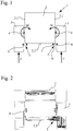
- FIG. 1 A tracked vehicle 1 with a vehicle trough 2 accommodating the vehicle crew and chain drives 3 arranged at the side of the vehicle trough 2 are shown.
- chain drives 3 are modular crawler tracks 3, which can be solved as a unit with comparatively little installation effort, for example, for transport purposes of the vehicle pan 2 and then connected to this again.
- the crawler tracks 3 are not directly, for example by screwing or welding, connected to the vehicle pan 2, but are vibration damped arranged on this.
- a plurality of bearings 4 are provided between the crawler tracks 3 and the vehicle pan 2, which allow a vibration-damped mounting of the crawler tracks 3 on the vehicle pan 2.
- the bearings 4 may be, for example, bolts that are inserted into an eye surrounding the bolt made of an elastomeric material.
- the elastomer material is chosen such that the bearings 4 behave resiliently in a certain range for damping the vibrations of the drives 3.
- Fig. 1 The contact forces F acting on the chain drives 3 cause a moment M. which rotates about the bearing points 4 according to the vehicle. Because of this moment M, the chain drives 3 tend to detach from the vehicle pan 2 in their lower region. In order to counteract these moments M, a moment support 5 is provided in the lower region of the vehicle pan 2, the extent that ensures a largely torque-resistant support of the crawler tracks 3 with respect to the bearings 4.
- the moment supports 5 are each formed by a train coupling 6, which extends between a dock-side coupling point 7 and a drive-side coupling point 8.
- These traction couplings 6 have rope-like properties, ie comparatively large tensile forces but almost no pressure and shear forces can be transmitted.
- both the dock-side coupling point 7 and the drive-side coupling point 8 are of plate-shaped geometry and each have openings 7.1. or 8.1, in which the wire loop-shaped train coupling 6 is arranged.
- One of the two coupling points 8 is formed in two parts, so that the wire loop 6 initially wrapped around the coupling point 7, then inserted into the lower half 8.2 of the coupling point 8 and finally can be fixed over the upper half of 8.3 of the coupling point 8.
- the train coupling 6 extends in an intermediate region between the two coupling points 7, 8 are free and the coupling points 7, 8 have a distance L, around which the chain drives 3 can move relative to the vehicle trough 2.
- a collision protection 10 is provided. This has a rising in the direction of the coupling points 7, 8 slope 10.1 and is of a total horseshoe-shaped geometry. Any objects slide when resting the vehicle 1 on the ground out on the collision 10 on the coupling points 7, 8 away, without that they are demolished.
- the tracked vehicle 1 described above is characterized by its only a short coupling path requiring torque arm 5, which extends a short distance from the track drive 3 to the vehicle pan 2. This results in a quasi simple as well as reliable vibration-decoupled connection of the track drive 3 to the vehicle trough 2 of the tracked vehicle 1 without disturbing impairment of any arranged below the vehicle floor 2.2 elements.
Landscapes
- Engineering & Computer Science (AREA)
- Chemical & Material Sciences (AREA)
- Combustion & Propulsion (AREA)
- Transportation (AREA)
- Mechanical Engineering (AREA)
- Vibration Prevention Devices (AREA)
Description
- Die vorliegende Erfindung betrifft ein Kettenfahrzeug, insbesondere ein militärisches Kettenfahrzeug, mit einer Fahrzeugwanne und zwei seitlich der Fahrzeugwanne schwingungsgedämpft angeordneten Kettenlaufwerken, die über eine Lagerstelle an der Fahrzeugwanne gelagert und über eine Momentenstütze gegenüber der Lagerstelle abgestützt sind.
- Derartige Kettenfahrzeuge werden beispielsweise im militärischen Bereich für verschiedene Einsatzzwecke beispielsweise als Kampfpanzer, Schützenpanzer, Transportfahrzeug, Amphibienfahrzeug oder ähnliches eingesetzt.
- In der zwischen den Kettenlaufwerken angeordneten Fahrzeugwanne wird häufig die mehrere Besatzungsmitglieder umfassende Besatzung des Fahrzeugs untergebracht. Aus diesem Grund ist es wichtig, dass die Kettenlaufwerke schwingungsgedämpft an der Fahrzeugwanne angeordnet sind, damit die im Fahrbetrieb durch die Ketten entstehenden Vibrationen nicht in die Wanne und damit auf die Fahrzeugbesatzung übertragen werden. Hierdurch ergeben sich besondere Anforderungen hinsichtlich der Befestigung der Kettenlaufwerke an der Fahrzeugwanne, die nicht starr, sondern zum Zwecke der Schwingungsdämpfung von dieser entkoppelt ausgebildet sein muss.
- Bei den Kettenlaufwerken handelt es sich häufig um modulare Kettenlaufwerke, die beispielsweise für Transportzwecke auf einfache Weise als Einheit von der Fahrzeugwanne abgekoppelt bzw. an dieser montiert werden können.
- Aus der
EP 0479016 A2 ist ein Kettenfahrzeug bekannt, dessen modulare Kettenlaufwerke an der Fahrzeugwanne schwingungsgedämpft angeordnet sind. Hierzu sind zumindest teilweise elastisch ausgebildete Lagerstellen vorgesehen, über welche die Kettenlaufwerke schwingungsgedämpft an der Fahrzeugwanne gelagert sind. Um die zum Teil erheblichen Aufstandskräfte wie auch die im Betrieb auftretenden fahrdynamischen Kräfte auffangen zu können und hierdurch ein Lösen der Kettenlaufwerke von den Lagerstellen zu vermeiden, sind stabartige Momentenstütze vorgesehen. Diese Momentenstützen sind nach Art von Zug- und Druckstangen ausgebildet, die sich von dem einen Kettenlaufwerk über die gesamte Fahrzeugbreite bis hin zu dem gegenüberliegenden Kettenlaufwerk erstrecken und diese miteinander koppeln. Hierdurch werden die beiden Kettenlaufwerke gegeneinander und damit auch gegenüber den elastischen Lagerstellen abgestützt. - Diese Art der Momentenstütze hat sich zur Abstützung schwingungsgedämpft angeordneter Kettenlaufwerke gegenüber deren Lagerstellen zwar durchaus bewährt, weist jedoch den Nachteil auf, dass sich die Zug- bzw. Druckstangen über die gesamte Fahrzeugbreite erstrecken, was bei bestimmten Arten von Fahrzeugen zu Problemen führen kann. Beispielsweise können diese Stangen aufgrund des langen Kopplungswegs einen unterhalb des Fahrzeugbodens angeordneten Minenschutz oder im Falle eines Amphibienfahrzeugs die teilweise im Fahrzeugboden angeordneten Ansaugöffnungen des Wasserfahrtantriebs beeinträchtigen.
- Aufgabe der vorliegenden Erfindung ist es daher, ein Kettenfahrzeug mit einer demgegenüber kompakteren und dadurch weniger Beeinträchtigungen hervorrufenden Momentenstütze anzugeben.
- Diese Aufgabe wird bei einem Kettenfahrzeug der eingangs genannten Art dadurch gelöst, dass die Momentenstütze von einer Zugkopplung gebildet wird, die sich zwischen einem wannenseitigen Kopplungspunkt und einem laufwerksseitigen Kopplungspunkt erstreckt.
- Bei einer solchen Momentenstütze ergeben sich kurze Kopplungswege und damit geringe Beeinträchtigungen des Fahrzeugs, da es nicht erforderlich ist, die Zugkopplung von einer Seite des Fahrzeugs quer über dessen gesamte Breite zur anderen Fahrzeugseite zu führen. Die Momentenstütze kann in kompakter Weise von Zugkopplungen gebildet werden, die sich von einem wannenseitigen Kopplungspunkt zu einem laufwerksseitigen Kopplungspunkt erstrecken. Die sich ergebenden Zugkräfte werden in der Fahrzeugwanne eingeleitet, Druckund Querkräfte wie diese durch die Schwingungen der Kette entstehen, werden über die Zugkopplung nicht eingeleitet. Es ergibt sich daher eine kompakte Momentenstütze bei gleichzeitig guter Schwingungsdämpfung.
- Gemäß einer vorteilhaften Weiterbildung der Erfindung wird vorgeschlagen, dass die Lagerstellen an einer Seitenwand und die Zugkopplungen am Boden der Fahrzeugwanne angeordnet sind. Die Lagerstellen können insbesondere höher liegen als die Zugkopplungen. Bei den Lagerstellen kann es sich beispielsweise um metallische Lagerzapfen handeln, welche in ein mit einem Elastomer versehenes Gelenkauge eingesteckt sind, wodurch sich eine schwingungsgedämpfte Lagerung ergibt. Durch die Anordnung der Zugkopplungen am Boden der Fahrzeugwanne ergibt sich eine zuverlässige Einleitung der Zugkräfte in die Wanne.
- Eine vorteilhafte Ausgestaltung der Erfindung sieht vor, dass über die Fahrzeuglänge verteilt mehrere Lagerstellen angeordnet sind. Beispielsweise können die Lagerstellen und die Zugkopplungen jeweils paarweise angeordnet und über die Länge des Fahrzeugs beispielsweise drei, vier, fünf oder mehr solcher Paare vorgesehen werden. Vorzugsweise sind die Lagerstellen zueinander in gleichmäßigen Abständen angeordnet.
- Eine vorteilhafte Ausgestaltung der Zugkopplungen sieht vor, dass diese elastische Ringe, insbesondere Drahtseilringe aufweisen. Über derartige Drahtseilringe lassen sich sehr große Zugkräfte übertragen. Gleichzeitig verhalten diese sich elastisch gegenüber Druck- und Querkräften, wodurch sich eine gute Schwingungsentkopplung erreichen lässt. Es werden nur Zug-, aber keine Druck- und Querkräfte übertragen. Als Drahtseilring können insbesondere Endlosdrahtseilringe verwendet werden, die teilweise auch als Grummet bezeichnet werden.
- Eine konstruktive Ausgestaltung der Erfindung sieht vor, dass der wannenseitige Kopplungspunkt unterhalb des Fahrzeugbodens angeordnet ist. In diesem Bereich kann die Zugkopplung auf einfache Weise an den Kopplungspunkt angebunden werden.
- Eine weitere Ausgestaltung sieht vor, dass der laufwerksseitige Kopplungspunkt dem wannenseitigen Kopplungspunkt auf gleicher Höhe gegenübersteht. Es ergibt sich auf diese Weise eine Übertragung der Zugkräfte in einer in etwa horizontalen Ebene.
- Eine weitere Ausgestaltung sieht vor, dass sich die Zugkopplungen zwischen dem wannenseitigen Kopplungspunkt und dem laufwerksseitigen Kopplungspunkt frei erstrecken. Im Bereich der freien Erstreckung der Zugkopplung können auf die Zugkopplung wirkende Druckkräfte abgefedert werden. Beispielsweise kann sich der laufwerksseitige Kopplungspunkt unter dem Einfluss einer hinreichend großen Druckkraft um einen gewissen Betrag auf den wannenseitigen Kopplungspunkt zubewegen, wodurch sich eine Schwingungsentkopplung erreichen lässt.
- Eine weitere Ausgestaltung sieht einen die Kopplungspunkte schützenden Anfahrschutz vor. Insbesondere bei militärischen Fahrzeugen kann es häufig vorkommen, dass diese in unebenem Gelände mit deren Boden auf dem Untergrund aufliegen. Um die Kopplungspunkte dabei vor Beschädigungen zu schützen, ist ein dies verhindernder Anfahrschutz vorgesehen.
- In Weiterbildung des Anfahrschutzes wird vorgeschlagen, dass dieser eine in Richtung der Kopplungspunkte ansteigende Anfahrschräge aufweist. Auf diese Weise wird ein Hinübergleiten unterhalb des Fahrzeugs angeordnete Gegenstände erleichtert und Beschädigungen der Kopplungspunkte vermieden.
- In konstruktiver Ausgestaltung wird weiter vorgeschlagen, dass der Anfahrschutz von U-förmiger, sich zur Fahrzeugseite hin öffnender Geometrie ist, wodurch sich ein Schutz der Kopplungspunkte aus allen vom Fahrzeugboden her weisenden Richtungen erreichen lässt.
- Schließlich wird gemäß einer weiteren Ausgestaltung vorgeschlagen, dass der Abstand der beiden Kopplungspunkte einstellbar ist. Beispielsweise können die Kopplungspunkte über Schraubverbindungen gehalten werden und zur Einstellung des Abstands Langlöcher vorgesehen werden. Über die Abstandseinstellung der Kopplungspunkte lässt sich die Spur der Kettenlaufwerke im Fahrbetrieb einstellen.
- Weitere Einzelheiten und Vorteile eines erfindungsgemäßen Kettenfahrzeugs werden nachfolgend unter Zuhilfenahme der beigefügten Zeichnungen eines Ausführungsbeispiels erläutert. Darin zeigen:
- Fig. 1
- eine schematische Prinzip-Ansicht eines Kettenfahrzeugs zur Veranschaulichung der Zusammenhänge
- Fig. 2
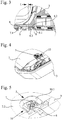
- eine der
Fig. 1 entsprechende, detaillierte Ansicht eines Kettenfahrzeugs - Fig. 3
- eine Detailansicht im Bereich einer Momentenstütze
- Fig. 4
- eine perspektivische Ansicht auf eine Momentenstütze und
- Fig. 5
- eine vergrößerte Ansicht einer Momentenstütze gemäß der perspektivischen Ansicht in
Fig. 4 . - In
Fig. 1 dargestellt ist ein Kettenfahrzeug 1 mit einer die Fahrzeugbesatzung aufnehmenden Fahrzeugwanne 2 und seitlich der Fahrzeugwanne 2 angeordneten Kettenlaufwerken 3. - Bei den Kettenlaufwerken 3 handelt es sich um modulare Kettenlaufwerke 3, welche mit als Einheit mit vergleichsweise wenig Montageaufwand beispielsweise zu Transportzwecken von der Fahrzeugwanne 2 gelöst und anschließend wieder mit dieser verbunden werden können.
- Um die von den Kettenlaufwerken 3 stammenden Vibrationen nicht direkt auf die Fahrzeugwanne 2 zu übertragen, sind die Kettenlaufwerke 3 nicht direkt, beispielsweise durch Verschrauben oder Verschweißen, mit der Fahrzeugwanne 2 verbunden, sondern sind schwingungsgedämpft an dieser angeordnet. Hierzu sind zwischen den Kettenlaufwerken 3 und der Fahrzeugwanne 2 mehrere Lagerstellen 4 vorgesehen, welche eine schwingungsgedämpfte Lagerung der Kettenlaufwerke 3 an der Fahrzeugwanne 2 erlauben. Bei den Lagerstellen 4 kann es sich beispielsweise um Bolzen handeln, die in ein den Bolzen umgebendes Auge aus einem Elastomer-Material eingesteckt sind. Das Elastomer-Material ist derart gewählt, dass sich die Lagerstellen 4 zur Dämpfung der Schwingungen der Laufwerke 3 in einem gewissen Bereich federelastisch verhalten.
- In
Fig. 1 schematisch eingezeichnet sind auch die auf die Kettenlaufwerke 3 einwirkenden Aufstandskräfte F. Diese Aufstandskräfte F bewirken ein um die Lagerstellen 4 nach fahrzeuginnen drehendes Moment M. Aufgrund dieses Moments M neigen die Kettenlaufwerke 3 dazu, sich in deren unterem Bereich von der Fahrzeugwanne 2 zu lösen. Um diesen Momenten M entgegenzuwirken, ist im unteren Bereich der Fahrzeugwanne 2 eine Momentenstütze 5 vorgesehen, die insoweit für eine weitgehend momentenfeste Abstützung der Kettenlaufwerke 3 gegenüber den Lagerstellen 4 sorgt. - Auf Einzelheiten der Momentenstützen 5 wird nachfolgend eingegangen werden.
- Wie
Fig. 1 dies zunächst erkennen lässt, befinden sich die Momentenstützen 5 im Bereich unterhalb des Bodens 2.2 der Fahrzeugwanne 2. Gebildet werden die Momentenstützen 5 jeweils von einer Zugkopplung 6, welche sich zwischen einem wannenseitigen Kopplungspunkt 7 und einem laufwerksseitigen Kopplungspunkt 8 erstreckt. Diese Zugkopplungen 6 weisen seilartige Eigenschaften auf, d.h. es können vergleichsweise große Zugkräfte aber nahezu keine Druckund Querkräfte übertragen werden. - Bei der Zugkopplung 6 handelt es sich gemäß der vergrößerten Darstellung beispielsweise in
Fig. 3 um einen endlosen Drahtseilring 6, welcher um die beiden Kopplungspunkte 7, 8 herum geführt ist. Beim Ausführungsbeispiel sind sowohl der wannenseitige Kopplungspunkt 7 als auch der laufwerksseitige Kopplungspunkt 8 von plattenförmiger Geometrie und weisen jeweils Öffnungen 7.1. bzw. 8.1 auf, in welchen die drahtschleifenförmige Zugkopplung 6 angeordnet ist. - Einer der beiden Kopplungspunkte 8 ist zweigeteilt ausgebildet, so dass die Drahtschleife 6 zunächst um den Kopplungspunkt 7 herumgelegt, anschließend in die untere Hälfte 8.2 des Kopplungspunktes 8 eingelegt und schließlich über die obere Hälfte 8.3 des Kopplungspunkts 8 fixiert werden kann.
- Wie sich der Darstellung in
Fig. 3 weiter entnehmen lässt, erstreckt sich die Zugkopplung 6 in einem Zwischenbereich zwischen den beiden Kopplungspunkten 7, 8 frei und die Kopplungspunkte 7, 8 weisen einen Abstand L auf, um welchem sich die Kettenlaufwerke 3 gegenüber der Fahrzeugwanne 2 bewegen können. - Um die beiden Kopplungspunkte 7, 8 unterhalb des Fahrzeugbodens 2.2 zu schützen, ist gemäß den Darstellungen in den
Fig. 4 und 5 ein Anfahrschutz 10 vorgesehen. Dieser weist eine in Richtung der Kopplungspunkte 7, 8 ansteigende Schräge 10.1 auf und ist von insgesamt hufeisenförmiger Geometrie. Etwaige Gegenstände gleiten beim Aufliegen des Fahrzeugs 1 auf dem Untergrund geführt über den Anfahrschutz 10 über die Kopplungspunkte 7, 8 hinweg, ohne dass diese abgerissen werden. - Das vorstehend beschriebene Kettenfahrzeug 1 zeichnet sich durch dessen nur einen kurzen Kopplungsweg erfordernde Momentenstütze 5 aus, die sich auf kurzem Weg von dem Kettenlaufwerk 3 hin zur Fahrzeugwanne 2 erstreckt. Es ergibt sich eine gleichsam einfache wie auch zuverlässige schwingungsentkoppelte Anbindung des Kettenlaufwerks 3 an die Fahrzeugwanne 2 des Kettenfahrzeugs 1 ohne störende Beeinträchtigung irgendwelcher unterhalb des Fahrzeugbodens 2.2 angeordneter Elemente.
-
- 1
- Kettenfahrzeug
- 2
- Fahrzeugwanne
- 2.1
- Seitenwand
- 2.2
- Boden
- 3
- Kettenlaufwerk
- 4
- Lagerstelle
- 5
- Momentenstütze
- 6
- Zugkopplung
- 7
- Kopplungspunkt
- 8
- Kopplungspunkt
- 10
- Anfahrschutz
- 10.1
- Anfahrschräge
- F
- Kraft
- M
- Moment
- L
- Abstand
Claims (11)
- Kettenfahrzeug mit einer Fahrzeugwanne (2) und zwei seitlich der Fahrzeugwanne (2) schwingungsgedämpft angeordneten Kettenlaufwerken (3), die über eine Lagerstelle (4) an der Fahrzeugwanne (2) gelagert und über eine Momentenstütze (5) gegenüber der Lagerstelle (4) abgestützt sind,
dadurch gekennzeichnet,
dass die Momentenstütze (5) von einer Zugkopplung (6) gebildet wird, die sich zwischen einem wannenseitigen Kopplungspunkt (7) und einem laufwerksseitigen Kopplungspunkt (8) erstreckt. - Kettenfahrzeug nach Anspruch 1, dadurch gekennzeichnet, dass die Lagerstellen (4) an einer Seitenwand (2.1) und die Zugkopplungen (6) am Boden (2.2) der Fahrzeugwanne (2) angeordnet sind.
- Kettenfahrzeug nach Anspruch 1 oder Anspruch 2, dadurch gekennzeichnet, dass über die Fahrzeuglänge verteilt mehrere Lagerstellen (4) und/oder Zugkopplungen (6) angeordnet sind.
- Kettenfahrzeug nach einem der vorhergehenden Ansprüche, dadurch gekennzeichnet, dass die Zugkopplungen (6) elastische Ringe, insbesondere Drahtseilringe aufweisen.
- Kettenfahrzeug nach einem der vorhergehenden Ansprüche, dadurch gekennzeichnet, dass der wannenseitige Kopplungspunkt (7) unterhalb des Fahrzeugbodens (2.2) angeordnet ist.
- Kettenfahrzeug nach einem der vorhergehenden Ansprüche, dadurch gekennzeichnet, dass der laufwerksseitige Kopplungspunkt (8) dem wannenseitigen Kopplungspunkt (7) auf gleicher Höhe gegenüber steht.
- Kettenfahrzeug nach einem der vorhergehenden Ansprüche, dadurch gekennzeichnet, dass sich die Zugkopplungen (6) zwischen dem wannenseitigen Kopplungspunkt (7) und dem laufwerksseitigen Kopplungspunkt (8) frei erstrecken.
- Kettenfahrzeug nach einem der vorhergehenden Ansprüche, gekennzeichnet durch einen die Kopplungspunkte (7, 8) schützenden Anfahrschutz (10).
- Kettenfahrzeug nach Anspruch 8, dadurch gekennzeichnet, dass der Anfahrschutz (10) eine in Richtung der Kopplungspunkte (7, 8) ansteigende Anfahrschräge (10.1) aufweist.
- Kettenfahrzeug nach einem der Ansprüche 8 oder 9, dadurch gekennzeichnet, dass der Anfahrschutz (10) von U-förmiger, sich zur Fahrzeugseite hin öffnender Geometrie ist.
- Kettenfahrzeug nach einem der vorhergehenden Ansprüche, dadurch gekennzeichnet, dass der Abstand der beiden Kopplungspunkte (7, 8) einstellbar ist.
Applications Claiming Priority (2)
| Application Number | Priority Date | Filing Date | Title |
|---|---|---|---|
| DE102014105476.8A DE102014105476B4 (de) | 2014-04-16 | 2014-04-16 | Militärisches Kettenfahrzeug |
| PCT/DE2015/100160 WO2015158333A1 (de) | 2014-04-16 | 2015-04-15 | Militärisches kettenfahrzeug |
Publications (2)
| Publication Number | Publication Date |
|---|---|
| EP3019390A1 EP3019390A1 (de) | 2016-05-18 |
| EP3019390B1 true EP3019390B1 (de) | 2016-12-28 |
Family
ID=53052641
Family Applications (1)
| Application Number | Title | Priority Date | Filing Date |
|---|---|---|---|
| EP15720591.5A Active EP3019390B1 (de) | 2014-04-16 | 2015-04-15 | Militärisches kettenfahrzeug |
Country Status (4)
| Country | Link |
|---|---|
| EP (1) | EP3019390B1 (de) |
| DE (1) | DE102014105476B4 (de) |
| ES (1) | ES2618307T3 (de) |
| WO (1) | WO2015158333A1 (de) |
Family Cites Families (2)
| Publication number | Priority date | Publication date | Assignee | Title |
|---|---|---|---|---|
| EP0479016B1 (de) * | 1990-10-01 | 1996-01-17 | Krauss-Maffei Aktiengesellschaft | Gleiskettenfahrzeug |
| WO2011154533A1 (de) * | 2010-06-10 | 2011-12-15 | Raipro Gmbh | Gurtbandlaufwerk und laufwerksachse mit gurtbandlaufwerken |
-
2014
- 2014-04-16 DE DE102014105476.8A patent/DE102014105476B4/de not_active Expired - Fee Related
-
2015
- 2015-04-15 EP EP15720591.5A patent/EP3019390B1/de active Active
- 2015-04-15 WO PCT/DE2015/100160 patent/WO2015158333A1/de not_active Ceased
- 2015-04-15 ES ES15720591.5T patent/ES2618307T3/es active Active
Non-Patent Citations (1)
| Title |
|---|
| None * |
Also Published As
| Publication number | Publication date |
|---|---|
| DE102014105476B4 (de) | 2015-10-29 |
| EP3019390A1 (de) | 2016-05-18 |
| ES2618307T3 (es) | 2017-06-21 |
| WO2015158333A1 (de) | 2015-10-22 |
| DE102014105476A1 (de) | 2015-10-22 |
Similar Documents
| Publication | Publication Date | Title |
|---|---|---|
| DE102010016605A1 (de) | Bodenwanne eines Fahrzeugs, insbesondere eines gepanzerten militärischen Fahrzeugs, und Zusatzpanzerung für eine Bodenwanne | |
| DE102014108380B4 (de) | Dämpfungsmodul für einen Fahrzeugsitz, ein Fahrzeugsitz und ein Fahrzeug | |
| DE102009013906A1 (de) | Ketten- und Transportförderband | |
| DE102014007907A1 (de) | Abstreifeinrichtung mit einer Abstreiferleiste für eine Bodenfräsmaschine, Abstreiferglied für eine Abstreiferleiste und Bodenfräsmaschine mit einer Abstreifeinrichtung | |
| EP2508407B1 (de) | Gerüst, insbesondere für elektrische Einrichtungen in einem Schienenfahrzeug, und Verfahren zur Herstellung des Gerüsts | |
| WO2019063397A1 (de) | Montagevorrichtung für eine stützvorrichtung | |
| DE102013011900B4 (de) | Kupplung mit flexiblem Element | |
| DE2710068A1 (de) | Winkelhebel-stangenverbindung in einer flugzeugsteuervorrichtung | |
| DE102006011336A1 (de) | Bauelement zur Wärmedämmung | |
| DE202017007410U1 (de) | Vorrichtung zur kraft- und/oder formschlüssigen Befestigung eines Bauteils an einem Fahrzeugrahmen | |
| DE102021102844B3 (de) | Mobilkran-Fahrzeugrahmen mit lösbar miteinander verbindbaren Rahmenteilen | |
| DE102014105476B4 (de) | Militärisches Kettenfahrzeug | |
| DE2229336A1 (de) | Fahrzeugrahmen | |
| EP3552931A1 (de) | Steighilfe | |
| DE102015114241B4 (de) | Holzzerkleinerer zum Einsatz an Böschungen | |
| DE2119246A1 (de) | Bruchabweiser, insbesondere für einen schreitenden Ausbau für Untertagebetriebe | |
| DE112015000133T5 (de) | Verbindungsstruktur | |
| EP2894258B1 (de) | Rammschutz | |
| DE102012004863A1 (de) | Traktor | |
| EP3472493B1 (de) | Vorrichtung zur kraftübertragung | |
| DE102013112198B4 (de) | Betonballastvorrichtung und System mit einer Betonballastvorrichtung und einer Landmaschine | |
| DE1680178A1 (de) | Rahmen,insbesondere fuer einen Gleiskettenschlepper | |
| DE102009023225A1 (de) | Minensichere Komponentenlagerung | |
| DE102009029910B4 (de) | Fahrzeug, insbesondere gepanzertes Fahrzeug mit einer die Besatzung des Fahrzeuges aufnehmenden Sicherheitszelle | |
| DE4407268B4 (de) | Verbindungsvorrichtung für eine Fahrzeug-Raupenkette |
Legal Events
| Date | Code | Title | Description |
|---|---|---|---|
| PUAI | Public reference made under article 153(3) epc to a published international application that has entered the european phase |
Free format text: ORIGINAL CODE: 0009012 |
|
| 17P | Request for examination filed |
Effective date: 20160209 |
|
| AK | Designated contracting states |
Kind code of ref document: A1 Designated state(s): AL AT BE BG CH CY CZ DE DK EE ES FI FR GB GR HR HU IE IS IT LI LT LU LV MC MK MT NL NO PL PT RO RS SE SI SK SM TR |
|
| AX | Request for extension of the european patent |
Extension state: BA ME |
|
| GRAP | Despatch of communication of intention to grant a patent |
Free format text: ORIGINAL CODE: EPIDOSNIGR1 |
|
| INTG | Intention to grant announced |
Effective date: 20160729 |
|
| GRAS | Grant fee paid |
Free format text: ORIGINAL CODE: EPIDOSNIGR3 |
|
| GRAJ | Information related to disapproval of communication of intention to grant by the applicant or resumption of examination proceedings by the epo deleted |
Free format text: ORIGINAL CODE: EPIDOSDIGR1 |
|
| GRAL | Information related to payment of fee for publishing/printing deleted |
Free format text: ORIGINAL CODE: EPIDOSDIGR3 |
|
| GRAR | Information related to intention to grant a patent recorded |
Free format text: ORIGINAL CODE: EPIDOSNIGR71 |
|
| GRAA | (expected) grant |
Free format text: ORIGINAL CODE: 0009210 |
|
| INTC | Intention to grant announced (deleted) | ||
| AK | Designated contracting states |
Kind code of ref document: B1 Designated state(s): AL AT BE BG CH CY CZ DE DK EE ES FI FR GB GR HR HU IE IS IT LI LT LU LV MC MK MT NL NO PL PT RO RS SE SI SK SM TR |
|
| DAV | Request for validation of the european patent (deleted) | ||
| DAX | Request for extension of the european patent (deleted) | ||
| INTG | Intention to grant announced |
Effective date: 20161121 |
|
| REG | Reference to a national code |
Ref country code: GB Ref legal event code: FG4D Free format text: NOT ENGLISH |
|
| REG | Reference to a national code |
Ref country code: CH Ref legal event code: EP |
|
| REG | Reference to a national code |
Ref country code: AT Ref legal event code: REF Ref document number: 857003 Country of ref document: AT Kind code of ref document: T Effective date: 20170115 |
|
| REG | Reference to a national code |
Ref country code: IE Ref legal event code: FG4D Free format text: LANGUAGE OF EP DOCUMENT: GERMAN |
|
| RIN2 | Information on inventor provided after grant (corrected) |
Inventor name: FALKE, THOMAS Inventor name: BACHMANN, HARALD |
|
| REG | Reference to a national code |
Ref country code: DE Ref legal event code: R096 Ref document number: 502015000443 Country of ref document: DE |
|
| PG25 | Lapsed in a contracting state [announced via postgrant information from national office to epo] |
Ref country code: LV Free format text: LAPSE BECAUSE OF FAILURE TO SUBMIT A TRANSLATION OF THE DESCRIPTION OR TO PAY THE FEE WITHIN THE PRESCRIBED TIME-LIMIT Effective date: 20161228 |
|
| REG | Reference to a national code |
Ref country code: SE Ref legal event code: TRGR |
|
| REG | Reference to a national code |
Ref country code: LT Ref legal event code: MG4D |
|
| PG25 | Lapsed in a contracting state [announced via postgrant information from national office to epo] |
Ref country code: GR Free format text: LAPSE BECAUSE OF FAILURE TO SUBMIT A TRANSLATION OF THE DESCRIPTION OR TO PAY THE FEE WITHIN THE PRESCRIBED TIME-LIMIT Effective date: 20170329 Ref country code: NO Free format text: LAPSE BECAUSE OF FAILURE TO SUBMIT A TRANSLATION OF THE DESCRIPTION OR TO PAY THE FEE WITHIN THE PRESCRIBED TIME-LIMIT Effective date: 20170328 Ref country code: LT Free format text: LAPSE BECAUSE OF FAILURE TO SUBMIT A TRANSLATION OF THE DESCRIPTION OR TO PAY THE FEE WITHIN THE PRESCRIBED TIME-LIMIT Effective date: 20161228 |
|
| REG | Reference to a national code |
Ref country code: NL Ref legal event code: MP Effective date: 20161228 |
|
| PG25 | Lapsed in a contracting state [announced via postgrant information from national office to epo] |
Ref country code: HR Free format text: LAPSE BECAUSE OF FAILURE TO SUBMIT A TRANSLATION OF THE DESCRIPTION OR TO PAY THE FEE WITHIN THE PRESCRIBED TIME-LIMIT Effective date: 20161228 Ref country code: RS Free format text: LAPSE BECAUSE OF FAILURE TO SUBMIT A TRANSLATION OF THE DESCRIPTION OR TO PAY THE FEE WITHIN THE PRESCRIBED TIME-LIMIT Effective date: 20161228 |
|
| REG | Reference to a national code |
Ref country code: ES Ref legal event code: FG2A Ref document number: 2618307 Country of ref document: ES Kind code of ref document: T3 Effective date: 20170621 |
|
| PG25 | Lapsed in a contracting state [announced via postgrant information from national office to epo] |
Ref country code: NL Free format text: LAPSE BECAUSE OF FAILURE TO SUBMIT A TRANSLATION OF THE DESCRIPTION OR TO PAY THE FEE WITHIN THE PRESCRIBED TIME-LIMIT Effective date: 20161228 |
|
| PG25 | Lapsed in a contracting state [announced via postgrant information from national office to epo] |
Ref country code: EE Free format text: LAPSE BECAUSE OF FAILURE TO SUBMIT A TRANSLATION OF THE DESCRIPTION OR TO PAY THE FEE WITHIN THE PRESCRIBED TIME-LIMIT Effective date: 20161228 Ref country code: CZ Free format text: LAPSE BECAUSE OF FAILURE TO SUBMIT A TRANSLATION OF THE DESCRIPTION OR TO PAY THE FEE WITHIN THE PRESCRIBED TIME-LIMIT Effective date: 20161228 Ref country code: RO Free format text: LAPSE BECAUSE OF FAILURE TO SUBMIT A TRANSLATION OF THE DESCRIPTION OR TO PAY THE FEE WITHIN THE PRESCRIBED TIME-LIMIT Effective date: 20161228 Ref country code: SK Free format text: LAPSE BECAUSE OF FAILURE TO SUBMIT A TRANSLATION OF THE DESCRIPTION OR TO PAY THE FEE WITHIN THE PRESCRIBED TIME-LIMIT Effective date: 20161228 Ref country code: IS Free format text: LAPSE BECAUSE OF FAILURE TO SUBMIT A TRANSLATION OF THE DESCRIPTION OR TO PAY THE FEE WITHIN THE PRESCRIBED TIME-LIMIT Effective date: 20170428 |
|
| PG25 | Lapsed in a contracting state [announced via postgrant information from national office to epo] |
Ref country code: SM Free format text: LAPSE BECAUSE OF FAILURE TO SUBMIT A TRANSLATION OF THE DESCRIPTION OR TO PAY THE FEE WITHIN THE PRESCRIBED TIME-LIMIT Effective date: 20161228 Ref country code: PT Free format text: LAPSE BECAUSE OF FAILURE TO SUBMIT A TRANSLATION OF THE DESCRIPTION OR TO PAY THE FEE WITHIN THE PRESCRIBED TIME-LIMIT Effective date: 20170428 Ref country code: PL Free format text: LAPSE BECAUSE OF FAILURE TO SUBMIT A TRANSLATION OF THE DESCRIPTION OR TO PAY THE FEE WITHIN THE PRESCRIBED TIME-LIMIT Effective date: 20161228 Ref country code: BG Free format text: LAPSE BECAUSE OF FAILURE TO SUBMIT A TRANSLATION OF THE DESCRIPTION OR TO PAY THE FEE WITHIN THE PRESCRIBED TIME-LIMIT Effective date: 20170328 |
|
| REG | Reference to a national code |
Ref country code: DE Ref legal event code: R097 Ref document number: 502015000443 Country of ref document: DE |
|
| PLBE | No opposition filed within time limit |
Free format text: ORIGINAL CODE: 0009261 |
|
| STAA | Information on the status of an ep patent application or granted ep patent |
Free format text: STATUS: NO OPPOSITION FILED WITHIN TIME LIMIT |
|
| PG25 | Lapsed in a contracting state [announced via postgrant information from national office to epo] |
Ref country code: DK Free format text: LAPSE BECAUSE OF FAILURE TO SUBMIT A TRANSLATION OF THE DESCRIPTION OR TO PAY THE FEE WITHIN THE PRESCRIBED TIME-LIMIT Effective date: 20161228 |
|
| 26N | No opposition filed |
Effective date: 20170929 |
|
| REG | Reference to a national code |
Ref country code: IE Ref legal event code: MM4A |
|
| REG | Reference to a national code |
Ref country code: FR Ref legal event code: ST Effective date: 20171229 |
|
| PG25 | Lapsed in a contracting state [announced via postgrant information from national office to epo] |
Ref country code: FR Free format text: LAPSE BECAUSE OF NON-PAYMENT OF DUE FEES Effective date: 20170502 Ref country code: MC Free format text: LAPSE BECAUSE OF FAILURE TO SUBMIT A TRANSLATION OF THE DESCRIPTION OR TO PAY THE FEE WITHIN THE PRESCRIBED TIME-LIMIT Effective date: 20161228 |
|
| PG25 | Lapsed in a contracting state [announced via postgrant information from national office to epo] |
Ref country code: SI Free format text: LAPSE BECAUSE OF FAILURE TO SUBMIT A TRANSLATION OF THE DESCRIPTION OR TO PAY THE FEE WITHIN THE PRESCRIBED TIME-LIMIT Effective date: 20161228 Ref country code: LU Free format text: LAPSE BECAUSE OF NON-PAYMENT OF DUE FEES Effective date: 20170415 |
|
| REG | Reference to a national code |
Ref country code: BE Ref legal event code: MM Effective date: 20170430 |
|
| PG25 | Lapsed in a contracting state [announced via postgrant information from national office to epo] |
Ref country code: IE Free format text: LAPSE BECAUSE OF NON-PAYMENT OF DUE FEES Effective date: 20170415 |
|
| PG25 | Lapsed in a contracting state [announced via postgrant information from national office to epo] |
Ref country code: BE Free format text: LAPSE BECAUSE OF NON-PAYMENT OF DUE FEES Effective date: 20170430 |
|
| PG25 | Lapsed in a contracting state [announced via postgrant information from national office to epo] |
Ref country code: MT Free format text: LAPSE BECAUSE OF FAILURE TO SUBMIT A TRANSLATION OF THE DESCRIPTION OR TO PAY THE FEE WITHIN THE PRESCRIBED TIME-LIMIT Effective date: 20161228 |
|
| REG | Reference to a national code |
Ref country code: CH Ref legal event code: PL |
|
| PG25 | Lapsed in a contracting state [announced via postgrant information from national office to epo] |
Ref country code: LI Free format text: LAPSE BECAUSE OF NON-PAYMENT OF DUE FEES Effective date: 20180430 Ref country code: CH Free format text: LAPSE BECAUSE OF NON-PAYMENT OF DUE FEES Effective date: 20180430 |
|
| PG25 | Lapsed in a contracting state [announced via postgrant information from national office to epo] |
Ref country code: HU Free format text: LAPSE BECAUSE OF FAILURE TO SUBMIT A TRANSLATION OF THE DESCRIPTION OR TO PAY THE FEE WITHIN THE PRESCRIBED TIME-LIMIT; INVALID AB INITIO Effective date: 20150415 |
|
| PG25 | Lapsed in a contracting state [announced via postgrant information from national office to epo] |
Ref country code: CY Free format text: LAPSE BECAUSE OF FAILURE TO SUBMIT A TRANSLATION OF THE DESCRIPTION OR TO PAY THE FEE WITHIN THE PRESCRIBED TIME-LIMIT Effective date: 20161228 |
|
| PG25 | Lapsed in a contracting state [announced via postgrant information from national office to epo] |
Ref country code: MK Free format text: LAPSE BECAUSE OF FAILURE TO SUBMIT A TRANSLATION OF THE DESCRIPTION OR TO PAY THE FEE WITHIN THE PRESCRIBED TIME-LIMIT Effective date: 20161228 |
|
| PG25 | Lapsed in a contracting state [announced via postgrant information from national office to epo] |
Ref country code: AL Free format text: LAPSE BECAUSE OF FAILURE TO SUBMIT A TRANSLATION OF THE DESCRIPTION OR TO PAY THE FEE WITHIN THE PRESCRIBED TIME-LIMIT Effective date: 20161228 |
|
| REG | Reference to a national code |
Ref country code: AT Ref legal event code: MM01 Ref document number: 857003 Country of ref document: AT Kind code of ref document: T Effective date: 20200415 |
|
| PG25 | Lapsed in a contracting state [announced via postgrant information from national office to epo] |
Ref country code: AT Free format text: LAPSE BECAUSE OF NON-PAYMENT OF DUE FEES Effective date: 20200415 |
|
| P01 | Opt-out of the competence of the unified patent court (upc) registered |
Effective date: 20230527 |
|
| REG | Reference to a national code |
Ref country code: DE Ref legal event code: R081 Ref document number: 502015000443 Country of ref document: DE Owner name: KNDS DEUTSCHLAND GMBH & CO. KG, DE Free format text: FORMER OWNER: KRAUSS-MAFFEI WEGMANN GMBH & CO. KG, 80997 MUENCHEN, DE |
|
| REG | Reference to a national code |
Ref country code: ES Ref legal event code: PC2A Owner name: KNDS DEUTSCHLAND GMBH & CO. KG Effective date: 20250304 |
|
| PGFP | Annual fee paid to national office [announced via postgrant information from national office to epo] |
Ref country code: FI Payment date: 20250417 Year of fee payment: 11 |
|
| PGFP | Annual fee paid to national office [announced via postgrant information from national office to epo] |
Ref country code: DE Payment date: 20250430 Year of fee payment: 11 |
|
| PGFP | Annual fee paid to national office [announced via postgrant information from national office to epo] |
Ref country code: ES Payment date: 20250519 Year of fee payment: 11 |
|
| PGFP | Annual fee paid to national office [announced via postgrant information from national office to epo] |
Ref country code: IT Payment date: 20250430 Year of fee payment: 11 |
|
| PGFP | Annual fee paid to national office [announced via postgrant information from national office to epo] |
Ref country code: TR Payment date: 20250407 Year of fee payment: 11 |
|
| PGFP | Annual fee paid to national office [announced via postgrant information from national office to epo] |
Ref country code: SE Payment date: 20250423 Year of fee payment: 11 |
|
| PGFP | Annual fee paid to national office [announced via postgrant information from national office to epo] |
Ref country code: GB Payment date: 20260324 Year of fee payment: 12 |