EP3018280A1 - Türantrieb - Google Patents
Türantrieb Download PDFInfo
- Publication number
- EP3018280A1 EP3018280A1 EP15003043.5A EP15003043A EP3018280A1 EP 3018280 A1 EP3018280 A1 EP 3018280A1 EP 15003043 A EP15003043 A EP 15003043A EP 3018280 A1 EP3018280 A1 EP 3018280A1
- Authority
- EP
- European Patent Office
- Prior art keywords
- housing
- drive
- link chain
- door
- telescopic section
- Prior art date
- Legal status (The legal status is an assumption and is not a legal conclusion. Google has not performed a legal analysis and makes no representation as to the accuracy of the status listed.)
- Granted
Links
Images


Classifications
-
- E—FIXED CONSTRUCTIONS
- E05—LOCKS; KEYS; WINDOW OR DOOR FITTINGS; SAFES
- E05F—DEVICES FOR MOVING WINGS INTO OPEN OR CLOSED POSITION; CHECKS FOR WINGS; WING FITTINGS NOT OTHERWISE PROVIDED FOR, CONCERNED WITH THE FUNCTIONING OF THE WING
- E05F15/00—Power-operated mechanisms for wings
- E05F15/60—Power-operated mechanisms for wings using electrical actuators
- E05F15/603—Power-operated mechanisms for wings using electrical actuators using rotary electromotors
- E05F15/611—Power-operated mechanisms for wings using electrical actuators using rotary electromotors for swinging wings
- E05F15/63—Power-operated mechanisms for wings using electrical actuators using rotary electromotors for swinging wings operated by swinging arms
-
- E—FIXED CONSTRUCTIONS
- E05—LOCKS; KEYS; WINDOW OR DOOR FITTINGS; SAFES
- E05F—DEVICES FOR MOVING WINGS INTO OPEN OR CLOSED POSITION; CHECKS FOR WINGS; WING FITTINGS NOT OTHERWISE PROVIDED FOR, CONCERNED WITH THE FUNCTIONING OF THE WING
- E05F15/00—Power-operated mechanisms for wings
- E05F15/60—Power-operated mechanisms for wings using electrical actuators
- E05F15/603—Power-operated mechanisms for wings using electrical actuators using rotary electromotors
- E05F15/611—Power-operated mechanisms for wings using electrical actuators using rotary electromotors for swinging wings
- E05F15/616—Power-operated mechanisms for wings using electrical actuators using rotary electromotors for swinging wings operated by push-pull mechanisms
- E05F15/619—Power-operated mechanisms for wings using electrical actuators using rotary electromotors for swinging wings operated by push-pull mechanisms using flexible or rigid rack-and-pinion arrangements
-
- E—FIXED CONSTRUCTIONS
- E05—LOCKS; KEYS; WINDOW OR DOOR FITTINGS; SAFES
- E05Y—INDEXING SCHEME RELATING TO HINGES OR OTHER SUSPENSION DEVICES FOR DOORS, WINDOWS OR WINGS AND DEVICES FOR MOVING WINGS INTO OPEN OR CLOSED POSITION, CHECKS FOR WINGS AND WING FITTINGS NOT OTHERWISE PROVIDED FOR, CONCERNED WITH THE FUNCTIONING OF THE WING
- E05Y2800/00—Details, accessories and auxiliary operations not otherwise provided for
- E05Y2800/10—Additional functions
- E05Y2800/122—Telescopic action
Definitions
- the invention relates to a door drive with the features of the preamble of claim 1.
- a door drive of the type in question is used both for driving the door leaf of a swing door and, although with certain modifications, for driving a door leaf of a sliding door.
- the state of the art from which the invention proceeds ( EP 1 643 065 A2 ), specifically relates to a door operator for a swing door.
- a door drive of the type in question as also shown in the prior art, from which the invention proceeds, basically includes an attachable to a door frame or on a door leaf drive unit and a corresponding thereto on the opposite component, ie on the door leaf or Door frame, attachable abutment. Between the drive unit and the abutment there extends a force transmission means, which is motor-displaceable relative to the drive unit, that is to say extendable and retractable.
- the drive element of the drive unit is a drive spindle there.
- a drive motor is used with a drive pinion, which acts on the power transmission means designed as a rack.
- a circular arc rack is proposed.
- the power transmission means is a link chain with a toothing.
- the drive unit has a drive pinion which is rotationally driven by the electric drive motor and forms a gear connection with the toothing of the link chain.
- the link chain In the extended state, the link chain is in the known in the art door drive between the drive unit and the abutment. In this state, the link chain is freely accessible, it can be dirty, but also forms a certain source of danger for careless users.
- the teaching of the present invention is based on the problem to optimize a door drive of the type in question in relation to the aforementioned problem.
- the link chain runs in a hollow telescopic rod, so that it is not accessible from the outside even in the extended state.
- the hollow telescopic pole has a fixed telescopic section, which is attached at one end to the housing of the drive unit. Opposite this fixed telescopic section at least one further telescopic section is displaceable. This is then a single stage telescopic pole.
- the displaceable telescope section with several displaceable telescopic sections of the last displaceable telescopic section, is mounted with its remote from the fixed telescopic section end to the abutment.
- the link chain of the power transmission means is longitudinally displaceable in the interior of the fixed telescopic section of the power transmission means. It is connected to the displaceable telescope section, with several displaceable telescopic sections with the last displaceable telescope section. It is particularly preferred if this connection is present at the end of the (last) displaceable telescope section remote from the abutment.
- the housing has a receptacle for the end of the fixed telescopic section, in which the end of the fixed telescopic section, preferably removable, is held.
- Swing doors are available with right or left stop. Even sliding doors are moved in opposite directions.
- the door drive according to the invention is universally applicable in a particularly useful manner, it is recommended according to the preferred teaching that the housing has two mutually parallel receptacles for the end of the fixed telescope section and that the end of the fixed telescopic section in the right stop in the one and left stop in the other recording is used.
- the housing has two receptacles lying parallel to one another, then only one of the two receptacles is filled in each case by the end of the fixed telescope section. Then there is the possibility that the storage room for the Link chain is at least partially formed by the not occupied by the end of the fixed telescopic section recording.
- a particularly elegant, structurally appropriate and tailored to the use of the hollow telescopic pole embodiment of the door drive according to the invention is characterized in that the housing elongated cuboid, optionally with rounded, executed that the inlet opening of the receptacle or the inlet openings of the recordings on a narrow side the housing is or are arranged and that the drive pinion is arranged near the opposite narrow side of the housing and the link chain runs there behind the drive pinion.
- a special arrangement of the drive motor within the housing of the drive unit In this arrangement, it is provided that in the interior of the housing one above the other two floors are formed and that in a floor, preferably the lower floor, the drive motor and possibly other components of the drive unit are arranged, while in the other floor, preferably the upper floor, the Drive pinion, the link chain, the storage space and the end of the fixed telescopic section are arranged.
- the invention relates to a door drive, the in Fig. 1 . 2 and 3 initially shown in total.
- the door drive has a on a door frame, which is not shown here, attachable drive unit 1 and a corresponding thereto attachable to a door leaf abutment 2.
- the arrangement can also be reversed with the drive unit 1 on the door and the abutment 2 on the door frame.
- the former variant is the more common, because then the regularly relatively heavy drive unit 1 does not have to be moved with the door leaf.
- the drive unit 1 is located on a pivot bearing block 3. This opposite the drive unit 1 itself is pivotable about a pivot axis.
- the pivot bearing block 3 is the component that is finally firmly attached to the door frame (or door leaf).
- the abutment 2 is likewise a bearing block forming a pivot bearing, which is then firmly attached to the door leaf (or the door frame).
- the power transmission means 4 comprises a link chain 5 ( Fig. 4, 5 ).
- the drive unit 1 has a housing 6 and in the housing 6 an electric drive motor 7 with a driving drive connected to the electric drive motor 7 drive pinion 8. Also this is allowed on 4 and 5 be referenced, which can recognize the interior of the drive unit 1 of the door drive. It will also open Fig. 3 referenced, in which the electric drive motor 7 is indicated in the interior of the housing 6. In Fig. 3 You can also see an indicated reduction gear 9 and a transmission shaft 10 to the drive pinion. 8
- the link chain 5 is engaged with the drive pinion 8 ( Fig. 4, 5 ) and can be pushed out of the housing 6 of the drive unit 1 or pulled into the housing 6 by turning the drive pinion 8.
- the power transmission means 4 in addition to the link chain 5 has a hollow telescopic rod with a fixed telescopic section 12 and at least one sliding telescopic section 13.
- the fixed telescopic section 12 is attached at one end to the housing 6 of the drive unit 1.
- the displaceable telescopic section 13 is attached at one end to the abutment 2.
- the link chain 5 is longitudinally displaceable in the interior of the fixed telescopic section 12. It is connected to the displaceable telescopic section 13, preferably at its end remote from the abutment 2. If the telescopic rod has more than one longitudinal telescopic section 13, the link chain 5 is connected to the last displaceable telescopic section 13.
- link chain 5 is connected to the distal end of the abutment 2 of the displaceable telescopic section 13.
- the link chain 5 can be displaced in the fixed telescopic section 12 by turning the drive pinion 8. Since it is connected to the inner end of the displaceable telescopic section 13, thereby the displaceable telescopic section 13 is displaced relative to the fixed telescopic section 12 and this opposite off or retracted.
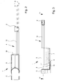
- Fig. 4 shows the retracted position while Fig. 5 shows the extended position.
- Fig. 1 and 2 the retracted position is shown in solid lines, the extended position in dotted lines.
- Fig. 1 . 4 and 5 shows that in the illustrated and preferred embodiment, the housing 6 of the drive unit 1 has a receptacle 14 for the end of the fixed telescopic section 12, in which the end of the fixed telescopic section 12, preferably removable, is held.
- Fig. 1 can be seen for the specific embodiment of this embodiment that the housing 6 has two parallel recesses 14.
- the end of the fixed telescopic section 12 can be inserted into the other receptacle 14 in the case of a right stop in the one and in the left stop.
- the end of the fixed telescopic section 12 of the telescopic rod is inserted into the right-side receptacle 14.
- Fig. 4 shows in conjunction with Fig. 5 in that the drive unit 1 is constructed here such that the storage space 11 for the link chain 5 is at least partially formed by the receptacle 14 not occupied by the end of the fixed telescope section 12.
- a symmetrical construction of the housing 6 with the drive pinion 8 enables this clever use of the interior of the housing 6.
- the housing 6 elongated cuboid and is here designed with rounded portions, that the inlet openings of the receptacles 14 are arranged on a narrow side 16 of the housing 6 and that the drive pinion 8 near the opposite narrow side 17th of the housing 6 is arranged and the link chain 5 runs there behind the drive pinion 8.
- Fig. 3 and 4 can be seen in connection with how the housing 6 of the drive unit 1 of the door drive according to the invention could be made relatively compact.
- a floor here and preferably the lower floor
- the drive motor 7 and possibly other components of the drive unit are arranged, while in the other floor, here and preferably the upper floor, the drive pinion 8, the link chain 5, the storage space 11 and the end of the fixed telescopic section 12 are arranged.
- the door drive according to the invention is elegant, slim design, very comfortable and largely maintenance-free, especially since the link chain 5 protected inside the telescopic sections 12, 13 of the telescopic rod runs.
- the housing 6 of the drive unit 1 is compact, because the arrangement with two floors here offers an optimal floor plan.
Abstract
Description
- Die Erfindung betrifft einen Türantrieb mit den Merkmalen des Oberbegriffs von Anspruch 1.
- Ein Türantrieb der in Rede stehenden Art ist sowohl für den Antrieb des Türblattes einer Drehflügeltür als auch, wenn auch mit gewissen Modifikationen, zum Antrieb eines Türblattes einer Schiebetür einsetzbar. Der Stand der Technik, von dem die Erfindung ausgeht (
EP 1 643 065 A2 ), betrifft speziell einen Türantrieb für eine Drehflügeltür. - Zu einem Türantrieb der in Rede stehenden Art, so auch dargestellt in dem Stand der Technik, von dem die Erfindung ausgeht, gehört grundsätzlich eine an einem Türrahmen oder an einem Türblatt anbringbare Antriebseinheit sowie ein korrespondierend dazu am gegenüberliegenden Bauteil, also an dem Türblatt oder dem Türrahmen, anbringbares Widerlager. Zwischen der Antriebseinheit und dem Widerlager erstreckt sich ein Kraftübertragungsmittel, das gegenüber der Antriebseinheit motorisch verlagerbar, also aus- und einfahrbar ist.
- Im Stand der Technik, von dem die Erfindung ausgeht, werden ausführlich verschiedene Arten von Türantrieben beschrieben. Bei einer ersten Alternative ist dort das Antriebselement der Antriebseinheit eine Antriebsspindel. In einer weiteren Alternative wird ein Antriebsmotor mit einem Antriebsritzel eingesetzt, der auf das als Zahnstange ausgeführte Kraftübertragungsmittel wirkt. Auch eine kreisbogenförmige Zahnstange wird vorgeschlagen. In einer weiteren Alternative ist das Kraftübertragungsmittel eine Gliederkette mit einer Verzahnung. Die Antriebseinheit weist ein Antriebsritzel auf, das vom elektrischen Antriebsmotor drehend angetrieben wird und mit der Verzahnung der Gliederkette eine Getriebeverbindung bildet. Im Stand der Technik wird zu dieser Variante darauf hingewiesen, dass sich diese Ausgestaltung durch besondere Kompaktheit der Antriebseinheit auszeichnet, da die Glieder der Gliederkette sich bei eingezogener Gliederkette im Inneren eines Aufbewahrungsraumes im Gehäuse der Antriebseinheit befinden, also dort gleichsam aufgerollt sind.
- Im Stand der Technik, von dem die Erfindung ausgeht, werden ausführlich Ausgestaltungen eines Türantriebs der in Rede stehenden Art beschrieben. Es handelt sich dabei um Ausgestaltungen einer Rutschkupplung, einer Steuerungselektronik, einer Drehzahlüberwachung, einer Programmierung, einer drahtlosen Fernbedienung, einer gekuppelten Betätigung einer Türfalle oder eines Türriegels etc. Ferner werden verschiedene Ausgestaltungen des elektrischen Antriebsmotors und verschiedene Getriebevarianten erläutert.
- Insgesamt wird für die Offenbarung von möglichen Varianten der Ausgestaltung eines Türantriebs der in Rede stehenden Art auf die
EP 1 643 065 A2 in Ihrer Gesamtheit verwiesen. - Für die Lehre der vorliegenden Erfindung wird von der Variante des aus dem Stand der Technik bekannten Türantriebes mit einer Gliederkette im Kraftübertragungsmittel ausgegangen. Die Gliederkette steht mit einem Antriebsritzel im Eingriff, das mit dem elektrischen Antriebsmotor antriebstechnisch verbunden ist. Durch Drehen des Antriebsritzels, angetrieben vom elektrischen Antriebsmotor, wird die Gliederkette aus dem Gehäuse der Antriebseinheit heraus geschoben oder in das Gehäuse hinein gezogen. Im eingefahrenen Zustand befindet sich die Gliederkette zum großen Teil im Aufbewahrungsraum im Gehäuse.
- Im ausgefahrenen Zustand liegt die Gliederkette bei dem im Stand der Technik bekannten Türantrieb frei zwischen der Antriebseinheit und dem Widerlager. In diesem Zustand ist die Gliederkette frei zugänglich, sie kann verschmutzen, bildet aber auch eine gewisse Gefahrenquelle für unvorsichtige Benutzer.
- Der Lehre der vorliegenden Erfindung liegt das Problem zugrunde, einen Türantrieb der in Rede stehenden Art in Bezug auf die zuvor genannte Problematik zu optimieren.
- Das zuvor aufgezeigte Problem ist bei einem Türantrieb mit den Merkmalen des Oberbegriffs von Anspruch 1 durch die Merkmale des kennzeichnenden Teils von Anspruch 1 gelöst.
- Erfindungsgemäß läuft die Gliederkette in einer hohlen Teleskopstange, so dass sie auch im ausgefahrenen Zustand von Außen nicht zugänglich ist. Die hohle Teleskopstange hat einen feststehenden Teleskopabschnitt, der mit einem Ende am Gehäuse der Antriebseinheit angebracht ist. Gegenüber diesem feststehenden Teleskopabschnitt ist mindestens ein weiterer Teleskopabschnitt verschiebbar. Das ist dann eine einstufige Teleskopstange. Grundsätzlich ist es auch möglich, mehrere verschiebbare Teleskopabschnitte vorzusehen, bspw. für eine zweistufige Teleskopstange. Welche Teleskopstange man einsetzt, ist von weiteren konstruktiven Überlegungen bestimmt.
- Der verschiebbare Teleskopabschnitt, bei mehreren verschiebbaren Teleskopabschnitten der letzte verschiebbare Teleskopabschnitt, ist mit seinem vom feststehenden Teleskopabschnitt entfernten Ende am Widerlager angebracht. Die Gliederkette des Kraftübertragungsmittels ist im Inneren des feststehenden Teleskopabschnittes des Kraftübertragungsmittels längs verschiebbar. Sie ist mit dem verschiebbaren Teleskopabschnitt, bei mehreren verschiebbaren Teleskopabschnitten mit dem letzten verschiebbaren Teleskopabschnitt, verbunden. Besonders bevorzugt ist es, wenn diese Verbindung an dem vom Widerlager entfernten Ende des (letzten) verschiebbaren Teleskopabschnittes vorliegt.
- Durch Drehen des Antriebsritzels, angetrieben vom elektrischen Antriebsmotor, ist also die Gliederkette im feststehenden Teleskopabschnitt in Längsrichtung verschiebbar. Dadurch wird der (letzte) verschiebbare Teleskopabschnitt ausgefahren bzw. eingefahren, je nach Richtung der Bewegung der Gliederkette. Die Gliederkette selbst befindet sich geschützt im Inneren der Teleskopstange, so dass sie weder verschmutzt noch eine Gefahr für eine Bedienungsperson darstellt.
- Bevorzugte Ausgestaltungen und weitere Ausbildungen des zuvor beschriebenen, erfindungsgemäßen Türantriebs sind Gegenstand der Unteransprüche.
- Besonders zweckmäßig ist es, wenn das Gehäuse eine Aufnahme für das Ende des feststehenden Teleskopabschnittes aufweist, in der das Ende des feststehenden Teleskopabschnittes, vorzugsweise herausnehmbar, gehalten ist.
- Drehflügeltüren gibt es mit Rechtsanschlag oder Linksanschlag. Auch Schiebetüren werden in einander entgegengesetzten Richtungen verschoben. Damit der erfindungsgemäße Türantrieb auf besonders zweckmäßige Weise universell einsetzbar ist, empfiehlt es sich nach bevorzugter Lehre, dass das Gehäuse zwei zueinander parallel liegende Aufnahmen für das Ende des feststehenden Teleskopabschnittes aufweist und dass das Ende des feststehenden Teleskopabschnittes bei Rechtsanschlag in der einen und bei Linksanschlag in der anderen Aufnahme eingesetzt ist.
- Hat das Gehäuse zwei zueinander parallel liegende Aufnahmen, so wird nur eine der beiden Aufnahmen jeweils vom Ende des feststehenden Teleskopabschnittes ausgefüllt. Dann ergibt sich die Möglichkeit, dass der Aufbewahrungsraum für die Gliederkette zumindest zum Teil von der nicht durch das Ende des feststehenden Teleskopabschnittes besetzten Aufnahme gebildet ist.
- Eine besonders elegante, konstruktiv zweckmäßige und auf die Verwendung der hohlen Teleskopstange abgestimmte Ausführung des erfindungsgemäßen Türantriebs zeichnet sich dadurch aus, dass das Gehäuse langgestreckt quaderförmig, gegebenenfalls mit Abrundungen, ausgeführt ist, dass die Eintrittsöffnung der Aufnahme bzw. die Eintrittsöffnungen der Aufnahmen an einer Schmalseite des Gehäuses angeordnet ist bzw. sind und dass das Antriebsritzel nahe der gegenüberliegenden Schmalseite des Gehäuses angeordnet ist und die Gliederkette dort hinter dem Antriebsritzel verläuft.
- Aus Gründen einer kompakten Ausführung der Antriebseinheit empfiehlt sich nach weiter bevorzugter Lehre der Erfindung eine besondere Anordnung des Antriebsmotors innerhalb des Gehäuses der Antriebseinheit. Bei dieser Anordnung ist vorgesehen, dass im Inneren des Gehäuses übereinander zwei Etagen ausgebildet sind und dass in einer Etage, vorzugsweise der unteren Etage, der Antriebsmotor und eventuell weitere Bauteile der Antriebseinheit angeordnet sind, während in der anderen Etage, vorzugsweise der oberen Etage, das Antriebsritzel, die Gliederkette, der Aufbewahrungsraum und das Ende des feststehenden Teleskopabschnitts angeordnet sind.
- Im Übrigen wird für anderweitige Ausgestaltungen aller Art, insbesondere auch hinsichtlich einer eventuellen Steuerelektronik für den elektrischen Antriebsmotor und sonstiger konstruktiver Besonderheiten, die man beim erfindungsgemäßen Türantrieb verwirklichen kann, auf die
EP 1 643 065 A2 verwiesen, die oben schon ausführlich behandelt worden ist. - Im Folgenden wird die Erfindung anhand einer lediglich ein bevorzugtes Ausführungsbeispiel darstellenden Zeichnung näher erläutert. In der Zeichnung zeigt
- Fig. 1
- in einer perspektivischen Darstellung ein bevorzugtes Ausführungsbeispiel eines erfindungsgemäßen Türantriebs in einer Ansicht schräg von oben,
- Fig. 2
- den Türantrieb aus
Fig. 1 in einer Ansicht von unten, - Fig. 3
- den Türantrieb aus
Fig. 1 in einer Ansicht von der Seite, - Fig. 4
- den Türantrieb aus
Fig. 3 im Schnitt entlang der Linie IV-IV, - Fig. 5
- den Türantrieb aus
Fig. 3 in einer Schnittdarstellung entsprechendFig. 4 , nun mit ausgefahrener Gliederkette. - Gegenstand der Erfindung ist ein Türantrieb, der in
Fig. 1 ,2 und 3 zunächst insgesamt dargestellt ist. Der Türantrieb hat eine an einem Türrahmen, der hier nicht dargestellt ist, anbringbare Antriebseinheit 1 und ein korrespondierend dazu an einem Türblatt anbringbares Widerlager 2. Die Anordnung kann auch umgekehrt mit der Antriebseinheit 1 am Türblatt und dem Widerlager 2 am Türrahmen gewählt werden. Die erstgenannte Variante ist aber die üblichere, weil dann die regelmäßig relativ schwere Antriebseinheit 1 nicht mit dem Türblatt mitbewegt werden muss. - Im in
Fig. 1 dargestellten Ausführungsbeispiel befindet sich die Antriebseinheit 1 an einem Schwenklagerbock 3. Diesem gegenüber ist die Antriebseinheit 1 selbst um eine Schwenkachse schwenkbar. Der Schwenklagerbock 3 ist das Bauteil, das letztlich am Türrahmen (oder am Türblatt) fest angebracht wird. - Bei dem Widerlager 2 handelt es sich vorliegend ebenfalls um einen ein Schwenklager bildenden Lagerbock, der für sich dann an dem Türblatt (oder dem Türrahmen) fest angebracht wird.
- Zwischen der Antriebseinheit 1 und dem Widerlager 2 erstreckt sich ein aus- und einfahrbares Kraftübertragungsmittel 4. Das Kraftübertragungsmittel 4 weist eine Gliederkette 5 auf (
Fig. 4, 5 ). - Die Antriebseinheit 1 weist ein Gehäuse 6 und in dem Gehäuse 6 einen elektrischen Antriebsmotor 7 mit einem mit dem elektrischen Antriebsmotor 7 antriebstechnisch verbundenen Antriebsritzel 8 auf. Auch hierzu darf auf
Fig. 4 und 5 verwiesen werden, die das Innere der Antriebseinheit 1 des Türantriebs erkennen lassen. Außerdem wird aufFig. 3 verwiesen, in der der elektrische Antriebsmotor 7 im Inneren des Gehäuses 6 angedeutet ist. InFig. 3 sieht man auch ein angedeutetes Untersetzungsgetriebe 9 und eine Übertragungswelle 10 zum Antriebsritzel 8. - Die Gliederkette 5 steht mit dem Antriebsritzel 8 im Eingriff (
Fig. 4, 5 ) und ist durch Drehen des Antriebsritzels 8 aus dem Gehäuse 6 der Antriebseinheit 1 herausschiebbar oder in das Gehäuse 6 hineinziehbar. - Aus
Fig. 4 lässt sich entnehmen, dass die Gliederkette 5 sich im eingefahrenen Zustand zum großen Teil in einem Aufbewahrungsraum 11 im Inneren des Gehäuses 6 befindet. Beim Einziehen der Gliederkette 5 durch das Antriebsritzel 8 legt sich diese mehr oder weniger von selbst im Inneren des Aufbewahrungsraums 11 im Gehäuse 6 ab. - Die Figuren zeigen im Zusammenhang nun, dass bei dem erfindungsgemäßen Türantrieb das Kraftübertragungsmittel 4 zusätzlich zur Gliederkette 5 eine hohle Teleskopstange mit einem feststehenden Teleskopabschnitt 12 und mindestens einem verschiebbaren Teleskopabschnitt 13 aufweist. Der feststehende Teleskopabschnitt 12 ist mit einem Ende am Gehäuse 6 der Antriebseinheit 1 angebracht. Der verschiebbare Teleskopabschnitt 13 ist mit einem Ende am Widerlager 2 angebracht. Die Gliederkette 5 ist im Inneren des feststehenden Teleskopabschnitts 12 längsverschiebbar. Sie ist mit dem verschiebbaren Teleskopabschnitt 13, vorzugsweise an dessen vom Widerlager 2 entfernten Ende, verbunden. Hat die Teleskopstange mehr als einen längs erschiebbaren Teleskopabschnitt 13, so ist die Gliederkette 5 mit dem letzten verschiebbaren Teleskopabschnitt 13 verbunden.
- Man sieht in
Fig. 4 und 5 im Zusammenhang, dass im dargestellten Ausführungsbeispiel in der Tat die Gliederkette 5 mit dem vom Widerlager 2 entfernten Ende des verschiebbaren Teleskopabschnittes 13 verbunden ist. - Bei der erfindungsgemäß verwirklichten Antriebseinheit 1, die hier dargestellt ist, ist durch Drehen des Antriebsritzels 8 die Gliederkette 5 im feststehenden Teleskopabschnitt 12 verschiebbar. Da sie mit dem inneren Ende des verschiebbaren Teleskopabschnittes 13 verbunden ist, wird dadurch der verschiebbare Teleskopabschnitt 13 gegenüber dem feststehenden Teleskopabschnitt 12 verschoben und diesem gegenüber aus- oder eingefahren.
-
Fig. 4 zeigt die eingefahrene Position, währendFig. 5 die ausgefahrene Position zeigt. In denFig. 1 und2 ist die eingefahrenen Position in durchgezogenen Linien gezeigt, die ausgefahrene Position in strichpunktierten Linien. - Aus
Fig. 1 ,4 und 5 ergibt sich, dass im dargestellten und bevorzugten Ausführungsbeispiel das Gehäuse 6 der Antriebseinheit 1 eine Aufnahme 14 für das Ende des feststehenden Teleskopabschnittes 12 aufweist, in der das Ende des feststehenden Teleskopabschnittes 12, vorzugsweise herausnehmbar, gehalten ist. -
Fig. 1 lässt dabei für die konkrete Ausgestaltung dieser Ausführungsform erkennen, dass das Gehäuse 6 zwei parallel liegende Aufnahmen 14 aufweist. Das Ende des feststehenden Teleskopabschnittes 12 ist bei Rechtsanschlag in die eine und bei Linksanschlag in die andere Aufnahme 14 einsetzbar. InFig. 1 ist das Ende des feststehenden Teleskopabschnittes 12 der Teleskopstange in die rechts liegende Aufnahme 14 eingesetzt. -
Fig. 4 zeigt in Verbindung mitFig. 5 , dass die Antriebseinheit 1 hier so konstruiert ist, dass der Aufbewahrungsraum 11 für die Gliederkette 5 zumindest zum Teil von der nicht durch das Ende des feststehenden Teleskopabschnittes 12 besetzten Aufnahme 14 gebildet ist. Ein symmetrischer Aufbau des Gehäuses 6 mit dem Antriebsritzel 8 ermöglicht diese geschickte Nutzung des Inneren des Gehäuses 6. - Das Einsetzen des Endes des feststehenden Teleskopabschnittes 12 in das Gehäuse 6 ist erfindungsgemäß dadurch leicht möglich, dass ein Deckel 15 des Gehäuses 6, der in
Fig. 1 besonders gut zu erkennen ist, abgeschraubt wird. Dann lässt sich das Ende des feststehenden Teleskopabschnittes 12 von oben in die Aufnahme 14 im Gehäuse 6 einsetzen. Dann wird der Deckel 15 wieder festgeschraubt und das Ende des feststehenden Teleskopabschnittes 12 ist im Gehäuse 6 fixiert. Bei abgenommenen Deckel 15 lässt sich auch die Gliederkette 5 bequem einlegen oder herausnehmen. - Die Figuren zeigen im Zusammenhang, dass nach weiter bevorzugter Lehre der Erfindung das Gehäuse 6 langgestreckt quaderförmig und hier mit Abrundungen ausgeführt ist, dass die Eintrittsöffnungen der Aufnahmen 14 an einer Schmalseite 16 des Gehäuses 6 angeordnet sind und dass das Antriebsritzel 8 nahe der gegenüberliegenden Schmalseite 17 des Gehäuses 6 angeordnet ist und die Gliederkette 5 dort hinter dem Antriebsritzel 8 verläuft.
-
Fig. 3 und4 lassen im Zusammenhang erkennen, wie das Gehäuse 6 der Antriebseinheit 1 des erfindungsgemäßen Türantriebs relativ kompakt bauend ausgeführt werden konnte. Hier ist nämlich zu erkennen, dass im Inneren des Gehäuses 6 übereinander zwei Etagen ausgebildet sind und dass in einer Etage, hier und vorzugsweise der unteren Etage, der Antriebsmotor 7 und eventuell weitere Bauteile der Antriebseinheit angeordnet sind, während in der anderen Etage, hier und vorzugsweise der oberen Etage, das Antriebsritzel 8, die Gliederkette 5, der Aufbewahrungsraum 11 und das Ende des feststehenden Teleskopabschnitts 12 angeordnet sind. - Die Anordnung des Antriebsmotors 7 mit Untersetzungsgetriebe 9 in der unteren Etage des Gehäuses 6 ist weiter oben schon im Einzelnen angesprochen worden. Das ist in
Fig. 3 gestrichelt dargestellt. - Insgesamt ist der erfindungsgemäße Türantrieb elegant, schlank bauend, sehr komfortabel und weitgehend wartungsfrei, insbesondere da die Gliederkette 5 geschützt im Inneren der Teleskopabschnitte 12, 13 der Teleskopstange läuft. Das Gehäuse 6 der Antriebseinheit 1 baut kompakt, weil die Anordnung mit zwei Etagen hier eine optimale Raumaufteilung bietet.
Claims (6)
- Türantrieb
mit einer an einem Türrahmen oder an einem Türblatt anbringbaren Antriebseinheit (1), einem korrespondierend dazu an dem Türblatt oder dem Türrahmen anbringbaren Widerlager (2) und einem sich zwischen der Antriebseinheit (1) und dem Widerlager (2) erstreckenden, aus- und einfahrbaren Kraftübertragungsmittel (4),
wobei das Kraftübertragungsmittel (4) eine Gliederkette (5) aufweist, wobei die Antriebseinheit (1) ein Gehäuse (6) und in dem Gehäuse (6) einen elektrischen Antriebsmotor (7) mit einem mit diesem antriebstechnisch verbundenen Antriebsritzel (8) sowie einen Aufbewahrungsraum (11) aufweist, wobei die Gliederkette (5) mit dem Antriebsritzel (8) im Eingriff steht und durch Drehen des Antriebsritzels (8) aus dem Gehäuse (6) herausschiebbar oder in das Gehäuse (6) hineinziehbar ist und sich im in das Gehäuse (6) hinein gezogenen Zustand zum großen Teil im Aufbewahrungsraum (11) im Gehäuse (6) befindet,
dadurch gekennzeichnet,
dass das Kraftübertragungsmittel (4) zusätzlich zur Gliederkette (5) eine hohle Teleskopstange mit einem feststehenden Teleskopabschnitt (12) und mindestens einem verschiebbaren Teleskopabschnitt (13) aufweist,
dass der feststehende Teleskopabschnitt (12) mit einem Ende am Gehäuse (6) der Antriebseinheit (1) angebracht ist,
dass der (letzte) verschiebbare Teleskopabschnitt (13) mit einem Ende am Widerlager (2) angebracht ist und
dass die Gliederkette (5) im Inneren des feststehenden Teleskopabschnitts (12) längs verschiebbar ist und mit dem (letzten) verschiebbaren Teleskopabschnitt (13), vorzugsweise an dessen vom Widerlager (2) entfernten Ende, verbunden ist,
so dass durch Drehen des Antriebsritzels (8) die Gliederkette (5) im feststehenden Teleskopabschnitt (12) in Längsrichtung verschiebbar und dadurch der (letzte) verschiebbare Teleskopabschnitt (13) aus- und einfahrbar ist. - Türantrieb nach Anspruch 1, dadurch gekennzeichnet,
dass das Gehäuse (6) eine Aufnahme (14) für das Ende des feststehenden Teleskopabschnittes (12) aufweist, in der das Ende des feststehenden Teleskopabschnittes (12), vorzugsweise herausnehmbar, gehalten ist. - Türantrieb nach Anspruch 2 , dadurch gekennzeichnet,
dass das Gehäuse (6) zwei zueinander parallel liegende Aufnahmen (14) für das Ende des feststehenden Teleskopabschnittes (12) aufweist und dass das Ende des feststehenden Teleskopabschnittes (12) bei Rechtsanschlag in der einen und bei Linksanschlag in der anderen Aufnahme (14) eingesetzt ist. - Türantrieb nach Anspruch 3, dadurch gekennzeichnet,
dass der Aufbewahrungsraum (11) für die Gliederkette (5) zumindest zum Teil von der nicht durch das Ende des feststehenden Teleskopabschnittes (12) besetzten Aufnahme (14) gebildet ist. - Türantrieb nach einem der Ansprüche 1 bis 4, dadurch gekennzeichnet,
dass das Gehäuse (6) langgestreckt quaderförmig, gegebenenfalls mit Abrundungen, ausgeführt ist,
dass die Eintrittsöffnung der Aufnahme (14) bzw. die Eintrittsöffnungen der Aufnahmen (14) an einer Schmalseite (16) des Gehäuses (6) angeordnet ist bzw. sind und
dass das Antriebsritzel (8) nahe der gegenüberliegenden Schmalseite (17) des Gehäuses (6) angeordnet ist und die Gliederkette (5) dort hinter dem Antriebsritzel (8) verläuft. - Türantrieb nach einem der Ansprüche 1 bis 5, dadurch gekennzeichnet,
dass im Inneren des Gehäuses (6) übereinander zwei Etagen ausgebildet sind und
dass in einer Etage, vorzugsweise der unteren Etage, der Antriebsmotor (7) und eventuell weitere Bauteile der Antriebseinheit angeordnet sind, während in der anderen Etage, vorzugsweise der oberen Etage, das Antriebsritzel (8), die Gliederkette (5), der Aufbewahrungsraum (11) und das Ende des feststehenden Teleskopabschnitts (12) angeordnet sind.
Applications Claiming Priority (1)
| Application Number | Priority Date | Filing Date | Title |
|---|---|---|---|
| DE202014008765.2U DE202014008765U1 (de) | 2014-11-06 | 2014-11-06 | Türantrieb |
Publications (2)
| Publication Number | Publication Date |
|---|---|
| EP3018280A1 true EP3018280A1 (de) | 2016-05-11 |
| EP3018280B1 EP3018280B1 (de) | 2020-04-22 |
Family
ID=52107697
Family Applications (1)
| Application Number | Title | Priority Date | Filing Date |
|---|---|---|---|
| EP15003043.5A Active EP3018280B1 (de) | 2014-11-06 | 2015-10-23 | Türantrieb |
Country Status (2)
| Country | Link |
|---|---|
| EP (1) | EP3018280B1 (de) |
| DE (1) | DE202014008765U1 (de) |
Families Citing this family (1)
| Publication number | Priority date | Publication date | Assignee | Title |
|---|---|---|---|---|
| DE202014010097U1 (de) | 2014-12-23 | 2015-02-06 | Wilhelm Rademacher | Türschließblechanordnung und Türanordnung mit einer solchen |
Citations (3)
| Publication number | Priority date | Publication date | Assignee | Title |
|---|---|---|---|---|
| EP1643065A2 (de) | 2004-10-04 | 2006-04-05 | Wilhelm Rademacher | Türantrieb |
| US20090107051A1 (en) * | 2007-10-29 | 2009-04-30 | Joseph Talpe | Closure mechanism |
| EP2607595A1 (de) * | 2011-12-20 | 2013-06-26 | Somfy SAS | Elektrischer Kettenschubantrieb für einen Flügel, und Montageverfahren eines Tors, das einen solchen Antrieb umfasst |
-
2014
- 2014-11-06 DE DE202014008765.2U patent/DE202014008765U1/de not_active Expired - Lifetime
-
2015
- 2015-10-23 EP EP15003043.5A patent/EP3018280B1/de active Active
Patent Citations (3)
| Publication number | Priority date | Publication date | Assignee | Title |
|---|---|---|---|---|
| EP1643065A2 (de) | 2004-10-04 | 2006-04-05 | Wilhelm Rademacher | Türantrieb |
| US20090107051A1 (en) * | 2007-10-29 | 2009-04-30 | Joseph Talpe | Closure mechanism |
| EP2607595A1 (de) * | 2011-12-20 | 2013-06-26 | Somfy SAS | Elektrischer Kettenschubantrieb für einen Flügel, und Montageverfahren eines Tors, das einen solchen Antrieb umfasst |
Also Published As
| Publication number | Publication date |
|---|---|
| EP3018280B1 (de) | 2020-04-22 |
| DE202014008765U1 (de) | 2014-12-04 |
Similar Documents
| Publication | Publication Date | Title |
|---|---|---|
| EP2851497B1 (de) | Justierbare Montagevorrichtung für ein Schiebeelement sowie Schiebevorrichtung | |
| EP1587701B1 (de) | Schwenkschiebetür für fahrzeuge | |
| EP2371337A1 (de) | Lenkrolle | |
| DE102015002945A1 (de) | Schublade, Möbelstück mit Schublade und Verfahren zum Öffnen einer Schublade | |
| EP3183996A1 (de) | Verstellvorrichtung, führungseinheit und möbel | |
| DE202012001762U1 (de) | Kettenantrieb für einen Stellantrieb zum automatischen Öffnen und Schließen einer Lüftungsvorrichtung | |
| EP0941889B1 (de) | Ausziehvorrichtung | |
| EP3665351A1 (de) | Scharnier für aushängbare blechschranktüren oder -wände | |
| EP1462594B2 (de) | Getriebe, insbesondere Schlagleistengetriebe für ein Fenster oder dergleichen | |
| EP2733286B1 (de) | Schwenkhebelverschluss mit geringer Einbautiefe | |
| EP3018280B1 (de) | Türantrieb | |
| DE3608988A1 (de) | Vorrichtung zur handbetaetigung einer elektromotorisch antreibbaren wickelwelle z.b. eines rolladens | |
| EP2960410B1 (de) | Schliesszylindervorrichtung für ein kraftfahrzeug mit einer koppeleinheit | |
| DE102014015388B4 (de) | Vorrichtung zum Betätigen einer Arretiereinrichtung | |
| DE10000162C2 (de) | Rolladenkasten | |
| DE10204744B4 (de) | Verschluss an einem Flügel eines Fensters, einer Tür od. dgl. mit einem Klappgriff | |
| EP3162994B1 (de) | Antriebsgetriebe für einen treibstangenbeschlag | |
| WO2015101429A1 (de) | Abdeckvorrichtung eines kofferraumfachs eines kraftfahrzeugs | |
| EP2851493A2 (de) | Türgriffanordnung für ein Kraftfahrzeug | |
| DE202010004097U1 (de) | Schiebewand | |
| DE10301584A1 (de) | Vorrichtung zur verschieblichen Anordnung eines Paneels | |
| EP0374271A1 (de) | Antriebseinheit für waagerecht mittels Rollen entlang einer Führungsschiene verschiebbares Tor | |
| EP2453191A2 (de) | Schubkastenkühlbox | |
| EP0439027B1 (de) | Einrichtung an einem Rolladen | |
| DE102014110411A1 (de) | Elektromechanisches Verschlusssystem für ein Möbel |
Legal Events
| Date | Code | Title | Description |
|---|---|---|---|
| PUAI | Public reference made under article 153(3) epc to a published international application that has entered the european phase |
Free format text: ORIGINAL CODE: 0009012 |
|
| AK | Designated contracting states |
Kind code of ref document: A1 Designated state(s): AL AT BE BG CH CY CZ DE DK EE ES FI FR GB GR HR HU IE IS IT LI LT LU LV MC MK MT NL NO PL PT RO RS SE SI SK SM TR |
|
| AX | Request for extension of the european patent |
Extension state: BA ME |
|
| STAA | Information on the status of an ep patent application or granted ep patent |
Free format text: STATUS: REQUEST FOR EXAMINATION WAS MADE |
|
| 17P | Request for examination filed |
Effective date: 20161028 |
|
| RBV | Designated contracting states (corrected) |
Designated state(s): AL AT BE BG CH CY CZ DE DK EE ES FI FR GB GR HR HU IE IS IT LI LT LU LV MC MK MT NL NO PL PT RO RS SE SI SK SM TR |
|
| RIC1 | Information provided on ipc code assigned before grant |
Ipc: E05F 15/619 20150101ALI20191017BHEP Ipc: E05F 15/63 20150101ALI20191017BHEP Ipc: E05F 15/611 20150101AFI20191017BHEP |
|
| GRAP | Despatch of communication of intention to grant a patent |
Free format text: ORIGINAL CODE: EPIDOSNIGR1 |
|
| STAA | Information on the status of an ep patent application or granted ep patent |
Free format text: STATUS: GRANT OF PATENT IS INTENDED |
|
| INTG | Intention to grant announced |
Effective date: 20191203 |
|
| GRAS | Grant fee paid |
Free format text: ORIGINAL CODE: EPIDOSNIGR3 |
|
| GRAA | (expected) grant |
Free format text: ORIGINAL CODE: 0009210 |
|
| STAA | Information on the status of an ep patent application or granted ep patent |
Free format text: STATUS: THE PATENT HAS BEEN GRANTED |
|
| AK | Designated contracting states |
Kind code of ref document: B1 Designated state(s): AL AT BE BG CH CY CZ DE DK EE ES FI FR GB GR HR HU IE IS IT LI LT LU LV MC MK MT NL NO PL PT RO RS SE SI SK SM TR |
|
| REG | Reference to a national code |
Ref country code: CH Ref legal event code: EP |
|
| REG | Reference to a national code |
Ref country code: DE Ref legal event code: R096 Ref document number: 502015012325 Country of ref document: DE |
|
| REG | Reference to a national code |
Ref country code: IE Ref legal event code: FG4D Free format text: LANGUAGE OF EP DOCUMENT: GERMAN |
|
| REG | Reference to a national code |
Ref country code: AT Ref legal event code: REF Ref document number: 1260278 Country of ref document: AT Kind code of ref document: T Effective date: 20200515 |
|
| REG | Reference to a national code |
Ref country code: LT Ref legal event code: MG4D |
|
| REG | Reference to a national code |
Ref country code: NL Ref legal event code: MP Effective date: 20200422 |
|
| PG25 | Lapsed in a contracting state [announced via postgrant information from national office to epo] |
Ref country code: IS Free format text: LAPSE BECAUSE OF FAILURE TO SUBMIT A TRANSLATION OF THE DESCRIPTION OR TO PAY THE FEE WITHIN THE PRESCRIBED TIME-LIMIT Effective date: 20200822 Ref country code: NO Free format text: LAPSE BECAUSE OF FAILURE TO SUBMIT A TRANSLATION OF THE DESCRIPTION OR TO PAY THE FEE WITHIN THE PRESCRIBED TIME-LIMIT Effective date: 20200722 Ref country code: GR Free format text: LAPSE BECAUSE OF FAILURE TO SUBMIT A TRANSLATION OF THE DESCRIPTION OR TO PAY THE FEE WITHIN THE PRESCRIBED TIME-LIMIT Effective date: 20200723 Ref country code: FI Free format text: LAPSE BECAUSE OF FAILURE TO SUBMIT A TRANSLATION OF THE DESCRIPTION OR TO PAY THE FEE WITHIN THE PRESCRIBED TIME-LIMIT Effective date: 20200422 Ref country code: SE Free format text: LAPSE BECAUSE OF FAILURE TO SUBMIT A TRANSLATION OF THE DESCRIPTION OR TO PAY THE FEE WITHIN THE PRESCRIBED TIME-LIMIT Effective date: 20200422 Ref country code: PT Free format text: LAPSE BECAUSE OF FAILURE TO SUBMIT A TRANSLATION OF THE DESCRIPTION OR TO PAY THE FEE WITHIN THE PRESCRIBED TIME-LIMIT Effective date: 20200824 Ref country code: NL Free format text: LAPSE BECAUSE OF FAILURE TO SUBMIT A TRANSLATION OF THE DESCRIPTION OR TO PAY THE FEE WITHIN THE PRESCRIBED TIME-LIMIT Effective date: 20200422 Ref country code: LT Free format text: LAPSE BECAUSE OF FAILURE TO SUBMIT A TRANSLATION OF THE DESCRIPTION OR TO PAY THE FEE WITHIN THE PRESCRIBED TIME-LIMIT Effective date: 20200422 |
|
| PG25 | Lapsed in a contracting state [announced via postgrant information from national office to epo] |
Ref country code: BG Free format text: LAPSE BECAUSE OF FAILURE TO SUBMIT A TRANSLATION OF THE DESCRIPTION OR TO PAY THE FEE WITHIN THE PRESCRIBED TIME-LIMIT Effective date: 20200722 Ref country code: RS Free format text: LAPSE BECAUSE OF FAILURE TO SUBMIT A TRANSLATION OF THE DESCRIPTION OR TO PAY THE FEE WITHIN THE PRESCRIBED TIME-LIMIT Effective date: 20200422 Ref country code: LV Free format text: LAPSE BECAUSE OF FAILURE TO SUBMIT A TRANSLATION OF THE DESCRIPTION OR TO PAY THE FEE WITHIN THE PRESCRIBED TIME-LIMIT Effective date: 20200422 Ref country code: HR Free format text: LAPSE BECAUSE OF FAILURE TO SUBMIT A TRANSLATION OF THE DESCRIPTION OR TO PAY THE FEE WITHIN THE PRESCRIBED TIME-LIMIT Effective date: 20200422 |
|
| PG25 | Lapsed in a contracting state [announced via postgrant information from national office to epo] |
Ref country code: AL Free format text: LAPSE BECAUSE OF FAILURE TO SUBMIT A TRANSLATION OF THE DESCRIPTION OR TO PAY THE FEE WITHIN THE PRESCRIBED TIME-LIMIT Effective date: 20200422 |
|
| REG | Reference to a national code |
Ref country code: DE Ref legal event code: R097 Ref document number: 502015012325 Country of ref document: DE |
|
| PG25 | Lapsed in a contracting state [announced via postgrant information from national office to epo] |
Ref country code: SM Free format text: LAPSE BECAUSE OF FAILURE TO SUBMIT A TRANSLATION OF THE DESCRIPTION OR TO PAY THE FEE WITHIN THE PRESCRIBED TIME-LIMIT Effective date: 20200422 Ref country code: EE Free format text: LAPSE BECAUSE OF FAILURE TO SUBMIT A TRANSLATION OF THE DESCRIPTION OR TO PAY THE FEE WITHIN THE PRESCRIBED TIME-LIMIT Effective date: 20200422 Ref country code: DK Free format text: LAPSE BECAUSE OF FAILURE TO SUBMIT A TRANSLATION OF THE DESCRIPTION OR TO PAY THE FEE WITHIN THE PRESCRIBED TIME-LIMIT Effective date: 20200422 Ref country code: RO Free format text: LAPSE BECAUSE OF FAILURE TO SUBMIT A TRANSLATION OF THE DESCRIPTION OR TO PAY THE FEE WITHIN THE PRESCRIBED TIME-LIMIT Effective date: 20200422 Ref country code: IT Free format text: LAPSE BECAUSE OF FAILURE TO SUBMIT A TRANSLATION OF THE DESCRIPTION OR TO PAY THE FEE WITHIN THE PRESCRIBED TIME-LIMIT Effective date: 20200422 Ref country code: CZ Free format text: LAPSE BECAUSE OF FAILURE TO SUBMIT A TRANSLATION OF THE DESCRIPTION OR TO PAY THE FEE WITHIN THE PRESCRIBED TIME-LIMIT Effective date: 20200422 Ref country code: ES Free format text: LAPSE BECAUSE OF FAILURE TO SUBMIT A TRANSLATION OF THE DESCRIPTION OR TO PAY THE FEE WITHIN THE PRESCRIBED TIME-LIMIT Effective date: 20200422 |
|
| PG25 | Lapsed in a contracting state [announced via postgrant information from national office to epo] |
Ref country code: PL Free format text: LAPSE BECAUSE OF FAILURE TO SUBMIT A TRANSLATION OF THE DESCRIPTION OR TO PAY THE FEE WITHIN THE PRESCRIBED TIME-LIMIT Effective date: 20200422 Ref country code: SK Free format text: LAPSE BECAUSE OF FAILURE TO SUBMIT A TRANSLATION OF THE DESCRIPTION OR TO PAY THE FEE WITHIN THE PRESCRIBED TIME-LIMIT Effective date: 20200422 |
|
| PLBE | No opposition filed within time limit |
Free format text: ORIGINAL CODE: 0009261 |
|
| STAA | Information on the status of an ep patent application or granted ep patent |
Free format text: STATUS: NO OPPOSITION FILED WITHIN TIME LIMIT |
|
| 26N | No opposition filed |
Effective date: 20210125 |
|
| PG25 | Lapsed in a contracting state [announced via postgrant information from national office to epo] |
Ref country code: SI Free format text: LAPSE BECAUSE OF FAILURE TO SUBMIT A TRANSLATION OF THE DESCRIPTION OR TO PAY THE FEE WITHIN THE PRESCRIBED TIME-LIMIT Effective date: 20200422 |
|
| REG | Reference to a national code |
Ref country code: CH Ref legal event code: PL |
|
| PG25 | Lapsed in a contracting state [announced via postgrant information from national office to epo] |
Ref country code: LU Free format text: LAPSE BECAUSE OF NON-PAYMENT OF DUE FEES Effective date: 20201023 Ref country code: MC Free format text: LAPSE BECAUSE OF FAILURE TO SUBMIT A TRANSLATION OF THE DESCRIPTION OR TO PAY THE FEE WITHIN THE PRESCRIBED TIME-LIMIT Effective date: 20200422 |
|
| REG | Reference to a national code |
Ref country code: BE Ref legal event code: MM Effective date: 20201031 |
|
| PG25 | Lapsed in a contracting state [announced via postgrant information from national office to epo] |
Ref country code: LI Free format text: LAPSE BECAUSE OF NON-PAYMENT OF DUE FEES Effective date: 20201031 Ref country code: BE Free format text: LAPSE BECAUSE OF NON-PAYMENT OF DUE FEES Effective date: 20201031 Ref country code: CH Free format text: LAPSE BECAUSE OF NON-PAYMENT OF DUE FEES Effective date: 20201031 |
|
| PG25 | Lapsed in a contracting state [announced via postgrant information from national office to epo] |
Ref country code: IE Free format text: LAPSE BECAUSE OF NON-PAYMENT OF DUE FEES Effective date: 20201023 |
|
| PGFP | Annual fee paid to national office [announced via postgrant information from national office to epo] |
Ref country code: AT Payment date: 20211021 Year of fee payment: 7 Ref country code: GB Payment date: 20211022 Year of fee payment: 7 Ref country code: DE Payment date: 20211020 Year of fee payment: 7 |
|
| PGFP | Annual fee paid to national office [announced via postgrant information from national office to epo] |
Ref country code: FR Payment date: 20211022 Year of fee payment: 7 |
|
| PG25 | Lapsed in a contracting state [announced via postgrant information from national office to epo] |
Ref country code: TR Free format text: LAPSE BECAUSE OF FAILURE TO SUBMIT A TRANSLATION OF THE DESCRIPTION OR TO PAY THE FEE WITHIN THE PRESCRIBED TIME-LIMIT Effective date: 20200422 Ref country code: MT Free format text: LAPSE BECAUSE OF FAILURE TO SUBMIT A TRANSLATION OF THE DESCRIPTION OR TO PAY THE FEE WITHIN THE PRESCRIBED TIME-LIMIT Effective date: 20200422 Ref country code: CY Free format text: LAPSE BECAUSE OF FAILURE TO SUBMIT A TRANSLATION OF THE DESCRIPTION OR TO PAY THE FEE WITHIN THE PRESCRIBED TIME-LIMIT Effective date: 20200422 |
|
| PG25 | Lapsed in a contracting state [announced via postgrant information from national office to epo] |
Ref country code: MK Free format text: LAPSE BECAUSE OF FAILURE TO SUBMIT A TRANSLATION OF THE DESCRIPTION OR TO PAY THE FEE WITHIN THE PRESCRIBED TIME-LIMIT Effective date: 20200422 |
|
| REG | Reference to a national code |
Ref country code: DE Ref legal event code: R119 Ref document number: 502015012325 Country of ref document: DE |
|
| REG | Reference to a national code |
Ref country code: AT Ref legal event code: MM01 Ref document number: 1260278 Country of ref document: AT Kind code of ref document: T Effective date: 20221023 |
|
| GBPC | Gb: european patent ceased through non-payment of renewal fee |
Effective date: 20221023 |
|
| PG25 | Lapsed in a contracting state [announced via postgrant information from national office to epo] |
Ref country code: FR Free format text: LAPSE BECAUSE OF NON-PAYMENT OF DUE FEES Effective date: 20221031 Ref country code: DE Free format text: LAPSE BECAUSE OF NON-PAYMENT OF DUE FEES Effective date: 20230503 Ref country code: AT Free format text: LAPSE BECAUSE OF NON-PAYMENT OF DUE FEES Effective date: 20221023 |
|
| PG25 | Lapsed in a contracting state [announced via postgrant information from national office to epo] |
Ref country code: GB Free format text: LAPSE BECAUSE OF NON-PAYMENT OF DUE FEES Effective date: 20221023 |