EP3018280A1 - Entraînement de porte - Google Patents
Entraînement de porte Download PDFInfo
- Publication number
- EP3018280A1 EP3018280A1 EP15003043.5A EP15003043A EP3018280A1 EP 3018280 A1 EP3018280 A1 EP 3018280A1 EP 15003043 A EP15003043 A EP 15003043A EP 3018280 A1 EP3018280 A1 EP 3018280A1
- Authority
- EP
- European Patent Office
- Prior art keywords
- housing
- drive
- link chain
- door
- telescopic section
- Prior art date
- Legal status (The legal status is an assumption and is not a legal conclusion. Google has not performed a legal analysis and makes no representation as to the accuracy of the status listed.)
- Granted
Links
- 230000005540 biological transmission Effects 0.000 claims abstract description 16
- 238000010276 construction Methods 0.000 description 1
- 230000001419 dependent effect Effects 0.000 description 1
- 238000003780 insertion Methods 0.000 description 1
- 230000037431 insertion Effects 0.000 description 1
- 238000012986 modification Methods 0.000 description 1
- 230000004048 modification Effects 0.000 description 1
- 238000012544 monitoring process Methods 0.000 description 1
Images


Classifications
-
- E—FIXED CONSTRUCTIONS
- E05—LOCKS; KEYS; WINDOW OR DOOR FITTINGS; SAFES
- E05F—DEVICES FOR MOVING WINGS INTO OPEN OR CLOSED POSITION; CHECKS FOR WINGS; WING FITTINGS NOT OTHERWISE PROVIDED FOR, CONCERNED WITH THE FUNCTIONING OF THE WING
- E05F15/00—Power-operated mechanisms for wings
- E05F15/60—Power-operated mechanisms for wings using electrical actuators
- E05F15/603—Power-operated mechanisms for wings using electrical actuators using rotary electromotors
- E05F15/611—Power-operated mechanisms for wings using electrical actuators using rotary electromotors for swinging wings
- E05F15/63—Power-operated mechanisms for wings using electrical actuators using rotary electromotors for swinging wings operated by swinging arms
-
- E—FIXED CONSTRUCTIONS
- E05—LOCKS; KEYS; WINDOW OR DOOR FITTINGS; SAFES
- E05F—DEVICES FOR MOVING WINGS INTO OPEN OR CLOSED POSITION; CHECKS FOR WINGS; WING FITTINGS NOT OTHERWISE PROVIDED FOR, CONCERNED WITH THE FUNCTIONING OF THE WING
- E05F15/00—Power-operated mechanisms for wings
- E05F15/60—Power-operated mechanisms for wings using electrical actuators
- E05F15/603—Power-operated mechanisms for wings using electrical actuators using rotary electromotors
- E05F15/611—Power-operated mechanisms for wings using electrical actuators using rotary electromotors for swinging wings
- E05F15/616—Power-operated mechanisms for wings using electrical actuators using rotary electromotors for swinging wings operated by push-pull mechanisms
- E05F15/619—Power-operated mechanisms for wings using electrical actuators using rotary electromotors for swinging wings operated by push-pull mechanisms using flexible or rigid rack-and-pinion arrangements
-
- E—FIXED CONSTRUCTIONS
- E05—LOCKS; KEYS; WINDOW OR DOOR FITTINGS; SAFES
- E05Y—INDEXING SCHEME ASSOCIATED WITH SUBCLASSES E05D AND E05F, RELATING TO CONSTRUCTION ELEMENTS, ELECTRIC CONTROL, POWER SUPPLY, POWER SIGNAL OR TRANSMISSION, USER INTERFACES, MOUNTING OR COUPLING, DETAILS, ACCESSORIES, AUXILIARY OPERATIONS NOT OTHERWISE PROVIDED FOR, APPLICATION THEREOF
- E05Y2800/00—Details, accessories and auxiliary operations not otherwise provided for
- E05Y2800/10—Additional functions
- E05Y2800/122—Telescopic action
Definitions
- the invention relates to a door drive with the features of the preamble of claim 1.
- a door drive of the type in question is used both for driving the door leaf of a swing door and, although with certain modifications, for driving a door leaf of a sliding door.
- the state of the art from which the invention proceeds ( EP 1 643 065 A2 ), specifically relates to a door operator for a swing door.
- a door drive of the type in question as also shown in the prior art, from which the invention proceeds, basically includes an attachable to a door frame or on a door leaf drive unit and a corresponding thereto on the opposite component, ie on the door leaf or Door frame, attachable abutment. Between the drive unit and the abutment there extends a force transmission means, which is motor-displaceable relative to the drive unit, that is to say extendable and retractable.
- the drive element of the drive unit is a drive spindle there.
- a drive motor is used with a drive pinion, which acts on the power transmission means designed as a rack.
- a circular arc rack is proposed.
- the power transmission means is a link chain with a toothing.
- the drive unit has a drive pinion which is rotationally driven by the electric drive motor and forms a gear connection with the toothing of the link chain.
- the link chain In the extended state, the link chain is in the known in the art door drive between the drive unit and the abutment. In this state, the link chain is freely accessible, it can be dirty, but also forms a certain source of danger for careless users.
- the teaching of the present invention is based on the problem to optimize a door drive of the type in question in relation to the aforementioned problem.
- the link chain runs in a hollow telescopic rod, so that it is not accessible from the outside even in the extended state.
- the hollow telescopic pole has a fixed telescopic section, which is attached at one end to the housing of the drive unit. Opposite this fixed telescopic section at least one further telescopic section is displaceable. This is then a single stage telescopic pole.
- the displaceable telescope section with several displaceable telescopic sections of the last displaceable telescopic section, is mounted with its remote from the fixed telescopic section end to the abutment.
- the link chain of the power transmission means is longitudinally displaceable in the interior of the fixed telescopic section of the power transmission means. It is connected to the displaceable telescope section, with several displaceable telescopic sections with the last displaceable telescope section. It is particularly preferred if this connection is present at the end of the (last) displaceable telescope section remote from the abutment.
- the housing has a receptacle for the end of the fixed telescopic section, in which the end of the fixed telescopic section, preferably removable, is held.
- Swing doors are available with right or left stop. Even sliding doors are moved in opposite directions.
- the door drive according to the invention is universally applicable in a particularly useful manner, it is recommended according to the preferred teaching that the housing has two mutually parallel receptacles for the end of the fixed telescope section and that the end of the fixed telescopic section in the right stop in the one and left stop in the other recording is used.
- the housing has two receptacles lying parallel to one another, then only one of the two receptacles is filled in each case by the end of the fixed telescope section. Then there is the possibility that the storage room for the Link chain is at least partially formed by the not occupied by the end of the fixed telescopic section recording.
- a particularly elegant, structurally appropriate and tailored to the use of the hollow telescopic pole embodiment of the door drive according to the invention is characterized in that the housing elongated cuboid, optionally with rounded, executed that the inlet opening of the receptacle or the inlet openings of the recordings on a narrow side the housing is or are arranged and that the drive pinion is arranged near the opposite narrow side of the housing and the link chain runs there behind the drive pinion.
- a special arrangement of the drive motor within the housing of the drive unit In this arrangement, it is provided that in the interior of the housing one above the other two floors are formed and that in a floor, preferably the lower floor, the drive motor and possibly other components of the drive unit are arranged, while in the other floor, preferably the upper floor, the Drive pinion, the link chain, the storage space and the end of the fixed telescopic section are arranged.
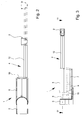
- the invention relates to a door drive, the in Fig. 1 . 2 and 3 initially shown in total.
- the door drive has a on a door frame, which is not shown here, attachable drive unit 1 and a corresponding thereto attachable to a door leaf abutment 2.
- the arrangement can also be reversed with the drive unit 1 on the door and the abutment 2 on the door frame.
- the former variant is the more common, because then the regularly relatively heavy drive unit 1 does not have to be moved with the door leaf.
- the drive unit 1 is located on a pivot bearing block 3. This opposite the drive unit 1 itself is pivotable about a pivot axis.
- the pivot bearing block 3 is the component that is finally firmly attached to the door frame (or door leaf).
- the abutment 2 is likewise a bearing block forming a pivot bearing, which is then firmly attached to the door leaf (or the door frame).
- the power transmission means 4 comprises a link chain 5 ( Fig. 4, 5 ).
- the drive unit 1 has a housing 6 and in the housing 6 an electric drive motor 7 with a driving drive connected to the electric drive motor 7 drive pinion 8. Also this is allowed on 4 and 5 be referenced, which can recognize the interior of the drive unit 1 of the door drive. It will also open Fig. 3 referenced, in which the electric drive motor 7 is indicated in the interior of the housing 6. In Fig. 3 You can also see an indicated reduction gear 9 and a transmission shaft 10 to the drive pinion. 8
- the link chain 5 is engaged with the drive pinion 8 ( Fig. 4, 5 ) and can be pushed out of the housing 6 of the drive unit 1 or pulled into the housing 6 by turning the drive pinion 8.
- the power transmission means 4 in addition to the link chain 5 has a hollow telescopic rod with a fixed telescopic section 12 and at least one sliding telescopic section 13.
- the fixed telescopic section 12 is attached at one end to the housing 6 of the drive unit 1.
- the displaceable telescopic section 13 is attached at one end to the abutment 2.
- the link chain 5 is longitudinally displaceable in the interior of the fixed telescopic section 12. It is connected to the displaceable telescopic section 13, preferably at its end remote from the abutment 2. If the telescopic rod has more than one longitudinal telescopic section 13, the link chain 5 is connected to the last displaceable telescopic section 13.
- link chain 5 is connected to the distal end of the abutment 2 of the displaceable telescopic section 13.
- the link chain 5 can be displaced in the fixed telescopic section 12 by turning the drive pinion 8. Since it is connected to the inner end of the displaceable telescopic section 13, thereby the displaceable telescopic section 13 is displaced relative to the fixed telescopic section 12 and this opposite off or retracted.
- Fig. 4 shows the retracted position while Fig. 5 shows the extended position.
- Fig. 1 and 2 the retracted position is shown in solid lines, the extended position in dotted lines.
- Fig. 1 . 4 and 5 shows that in the illustrated and preferred embodiment, the housing 6 of the drive unit 1 has a receptacle 14 for the end of the fixed telescopic section 12, in which the end of the fixed telescopic section 12, preferably removable, is held.
- Fig. 1 can be seen for the specific embodiment of this embodiment that the housing 6 has two parallel recesses 14.
- the end of the fixed telescopic section 12 can be inserted into the other receptacle 14 in the case of a right stop in the one and in the left stop.
- the end of the fixed telescopic section 12 of the telescopic rod is inserted into the right-side receptacle 14.
- Fig. 4 shows in conjunction with Fig. 5 in that the drive unit 1 is constructed here such that the storage space 11 for the link chain 5 is at least partially formed by the receptacle 14 not occupied by the end of the fixed telescope section 12.
- a symmetrical construction of the housing 6 with the drive pinion 8 enables this clever use of the interior of the housing 6.
- the housing 6 elongated cuboid and is here designed with rounded portions, that the inlet openings of the receptacles 14 are arranged on a narrow side 16 of the housing 6 and that the drive pinion 8 near the opposite narrow side 17th of the housing 6 is arranged and the link chain 5 runs there behind the drive pinion 8.
- Fig. 3 and 4 can be seen in connection with how the housing 6 of the drive unit 1 of the door drive according to the invention could be made relatively compact.
- a floor here and preferably the lower floor
- the drive motor 7 and possibly other components of the drive unit are arranged, while in the other floor, here and preferably the upper floor, the drive pinion 8, the link chain 5, the storage space 11 and the end of the fixed telescopic section 12 are arranged.
- the door drive according to the invention is elegant, slim design, very comfortable and largely maintenance-free, especially since the link chain 5 protected inside the telescopic sections 12, 13 of the telescopic rod runs.
- the housing 6 of the drive unit 1 is compact, because the arrangement with two floors here offers an optimal floor plan.
Landscapes
- Power-Operated Mechanisms For Wings (AREA)
Applications Claiming Priority (1)
| Application Number | Priority Date | Filing Date | Title |
|---|---|---|---|
| DE202014008765.2U DE202014008765U1 (de) | 2014-11-06 | 2014-11-06 | Türantrieb |
Publications (2)
| Publication Number | Publication Date |
|---|---|
| EP3018280A1 true EP3018280A1 (fr) | 2016-05-11 |
| EP3018280B1 EP3018280B1 (fr) | 2020-04-22 |
Family
ID=52107697
Family Applications (1)
| Application Number | Title | Priority Date | Filing Date |
|---|---|---|---|
| EP15003043.5A Active EP3018280B1 (fr) | 2014-11-06 | 2015-10-23 | Entraînement de porte |
Country Status (2)
| Country | Link |
|---|---|
| EP (1) | EP3018280B1 (fr) |
| DE (1) | DE202014008765U1 (fr) |
Families Citing this family (1)
| Publication number | Priority date | Publication date | Assignee | Title |
|---|---|---|---|---|
| DE202014010097U1 (de) | 2014-12-23 | 2015-02-06 | Wilhelm Rademacher | Türschließblechanordnung und Türanordnung mit einer solchen |
Citations (3)
| Publication number | Priority date | Publication date | Assignee | Title |
|---|---|---|---|---|
| EP1643065A2 (fr) | 2004-10-04 | 2006-04-05 | Wilhelm Rademacher | Dispositif d'entraînement d'une porte |
| US20090107051A1 (en) * | 2007-10-29 | 2009-04-30 | Joseph Talpe | Closure mechanism |
| EP2607595A1 (fr) * | 2011-12-20 | 2013-06-26 | Somfy SAS | Actionneur électrique à chaîne pour ouvrant et procédé de montage d'un portail comprenant un tel actionneur |
-
2014
- 2014-11-06 DE DE202014008765.2U patent/DE202014008765U1/de not_active Expired - Lifetime
-
2015
- 2015-10-23 EP EP15003043.5A patent/EP3018280B1/fr active Active
Patent Citations (3)
| Publication number | Priority date | Publication date | Assignee | Title |
|---|---|---|---|---|
| EP1643065A2 (fr) | 2004-10-04 | 2006-04-05 | Wilhelm Rademacher | Dispositif d'entraînement d'une porte |
| US20090107051A1 (en) * | 2007-10-29 | 2009-04-30 | Joseph Talpe | Closure mechanism |
| EP2607595A1 (fr) * | 2011-12-20 | 2013-06-26 | Somfy SAS | Actionneur électrique à chaîne pour ouvrant et procédé de montage d'un portail comprenant un tel actionneur |
Also Published As
| Publication number | Publication date |
|---|---|
| DE202014008765U1 (de) | 2014-12-04 |
| EP3018280B1 (fr) | 2020-04-22 |
Similar Documents
| Publication | Publication Date | Title |
|---|---|---|
| EP2851497B1 (fr) | Dispositif de montage réglable pour un élément coulissant et dispositif coulissant | |
| EP1587701B1 (fr) | Portière coulissante pivotante pour véhicules | |
| EP2371337A1 (fr) | Galet de direction | |
| DE102015002945A1 (de) | Schublade, Möbelstück mit Schublade und Verfahren zum Öffnen einer Schublade | |
| EP3183996A1 (fr) | Dispositif de réglage, unité de guidage et meuble | |
| DE202012001762U1 (de) | Kettenantrieb für einen Stellantrieb zum automatischen Öffnen und Schließen einer Lüftungsvorrichtung | |
| EP0941889B1 (fr) | Dispositif d'extraction | |
| EP3665351A1 (fr) | Charnière pour portes ou parois amovibles d'armoire en tôle | |
| DE102015206424A1 (de) | Schneidvorrichtung umfassend zwei Klingen, von denen wenigstens eine über eine Antriebseinrichtung bewegbar ist | |
| DE102012111095B4 (de) | Schwenkhebelverschluss mit geringer Einbautiefe | |
| EP3018280B1 (fr) | Entraînement de porte | |
| DE3608988A1 (de) | Vorrichtung zur handbetaetigung einer elektromotorisch antreibbaren wickelwelle z.b. eines rolladens | |
| DE102018220080A1 (de) | Kinematik für Fahrzeug-Klappe | |
| EP2960410B1 (fr) | Dispositif de cylindre de fermeture pour un vehicule automobile dote d'un coupleur | |
| DE102014015388B4 (de) | Vorrichtung zum Betätigen einer Arretiereinrichtung | |
| DE10000162C2 (de) | Rolladenkasten | |
| DE10204744B4 (de) | Verschluss an einem Flügel eines Fensters, einer Tür od. dgl. mit einem Klappgriff | |
| EP3162994B1 (fr) | Mécanisme d'entraînement pour une ferrure à crémone | |
| WO2015101429A1 (fr) | Dispositif de recouvrement d'un compartiment de coffre à bagages d'un véhicule automobile | |
| EP2851493A2 (fr) | Poignée de porte pour un véhicule automobile | |
| DE202010004097U1 (de) | Schiebewand | |
| DE10301584A1 (de) | Vorrichtung zur verschieblichen Anordnung eines Paneels | |
| EP2453191A2 (fr) | Boîte réfrigérante à tiroir coulissant | |
| EP0439027B1 (fr) | Dispositif pour volets roulants | |
| DE102014110411A1 (de) | Elektromechanisches Verschlusssystem für ein Möbel |
Legal Events
| Date | Code | Title | Description |
|---|---|---|---|
| PUAI | Public reference made under article 153(3) epc to a published international application that has entered the european phase |
Free format text: ORIGINAL CODE: 0009012 |
|
| AK | Designated contracting states |
Kind code of ref document: A1 Designated state(s): AL AT BE BG CH CY CZ DE DK EE ES FI FR GB GR HR HU IE IS IT LI LT LU LV MC MK MT NL NO PL PT RO RS SE SI SK SM TR |
|
| AX | Request for extension of the european patent |
Extension state: BA ME |
|
| STAA | Information on the status of an ep patent application or granted ep patent |
Free format text: STATUS: REQUEST FOR EXAMINATION WAS MADE |
|
| 17P | Request for examination filed |
Effective date: 20161028 |
|
| RBV | Designated contracting states (corrected) |
Designated state(s): AL AT BE BG CH CY CZ DE DK EE ES FI FR GB GR HR HU IE IS IT LI LT LU LV MC MK MT NL NO PL PT RO RS SE SI SK SM TR |
|
| RIC1 | Information provided on ipc code assigned before grant |
Ipc: E05F 15/619 20150101ALI20191017BHEP Ipc: E05F 15/63 20150101ALI20191017BHEP Ipc: E05F 15/611 20150101AFI20191017BHEP |
|
| GRAP | Despatch of communication of intention to grant a patent |
Free format text: ORIGINAL CODE: EPIDOSNIGR1 |
|
| STAA | Information on the status of an ep patent application or granted ep patent |
Free format text: STATUS: GRANT OF PATENT IS INTENDED |
|
| INTG | Intention to grant announced |
Effective date: 20191203 |
|
| GRAS | Grant fee paid |
Free format text: ORIGINAL CODE: EPIDOSNIGR3 |
|
| GRAA | (expected) grant |
Free format text: ORIGINAL CODE: 0009210 |
|
| STAA | Information on the status of an ep patent application or granted ep patent |
Free format text: STATUS: THE PATENT HAS BEEN GRANTED |
|
| AK | Designated contracting states |
Kind code of ref document: B1 Designated state(s): AL AT BE BG CH CY CZ DE DK EE ES FI FR GB GR HR HU IE IS IT LI LT LU LV MC MK MT NL NO PL PT RO RS SE SI SK SM TR |
|
| REG | Reference to a national code |
Ref country code: CH Ref legal event code: EP |
|
| REG | Reference to a national code |
Ref country code: DE Ref legal event code: R096 Ref document number: 502015012325 Country of ref document: DE |
|
| REG | Reference to a national code |
Ref country code: IE Ref legal event code: FG4D Free format text: LANGUAGE OF EP DOCUMENT: GERMAN |
|
| REG | Reference to a national code |
Ref country code: AT Ref legal event code: REF Ref document number: 1260278 Country of ref document: AT Kind code of ref document: T Effective date: 20200515 |
|
| REG | Reference to a national code |
Ref country code: LT Ref legal event code: MG4D |
|
| REG | Reference to a national code |
Ref country code: NL Ref legal event code: MP Effective date: 20200422 |
|
| PG25 | Lapsed in a contracting state [announced via postgrant information from national office to epo] |
Ref country code: IS Free format text: LAPSE BECAUSE OF FAILURE TO SUBMIT A TRANSLATION OF THE DESCRIPTION OR TO PAY THE FEE WITHIN THE PRESCRIBED TIME-LIMIT Effective date: 20200822 Ref country code: NO Free format text: LAPSE BECAUSE OF FAILURE TO SUBMIT A TRANSLATION OF THE DESCRIPTION OR TO PAY THE FEE WITHIN THE PRESCRIBED TIME-LIMIT Effective date: 20200722 Ref country code: GR Free format text: LAPSE BECAUSE OF FAILURE TO SUBMIT A TRANSLATION OF THE DESCRIPTION OR TO PAY THE FEE WITHIN THE PRESCRIBED TIME-LIMIT Effective date: 20200723 Ref country code: FI Free format text: LAPSE BECAUSE OF FAILURE TO SUBMIT A TRANSLATION OF THE DESCRIPTION OR TO PAY THE FEE WITHIN THE PRESCRIBED TIME-LIMIT Effective date: 20200422 Ref country code: SE Free format text: LAPSE BECAUSE OF FAILURE TO SUBMIT A TRANSLATION OF THE DESCRIPTION OR TO PAY THE FEE WITHIN THE PRESCRIBED TIME-LIMIT Effective date: 20200422 Ref country code: PT Free format text: LAPSE BECAUSE OF FAILURE TO SUBMIT A TRANSLATION OF THE DESCRIPTION OR TO PAY THE FEE WITHIN THE PRESCRIBED TIME-LIMIT Effective date: 20200824 Ref country code: NL Free format text: LAPSE BECAUSE OF FAILURE TO SUBMIT A TRANSLATION OF THE DESCRIPTION OR TO PAY THE FEE WITHIN THE PRESCRIBED TIME-LIMIT Effective date: 20200422 Ref country code: LT Free format text: LAPSE BECAUSE OF FAILURE TO SUBMIT A TRANSLATION OF THE DESCRIPTION OR TO PAY THE FEE WITHIN THE PRESCRIBED TIME-LIMIT Effective date: 20200422 |
|
| PG25 | Lapsed in a contracting state [announced via postgrant information from national office to epo] |
Ref country code: BG Free format text: LAPSE BECAUSE OF FAILURE TO SUBMIT A TRANSLATION OF THE DESCRIPTION OR TO PAY THE FEE WITHIN THE PRESCRIBED TIME-LIMIT Effective date: 20200722 Ref country code: RS Free format text: LAPSE BECAUSE OF FAILURE TO SUBMIT A TRANSLATION OF THE DESCRIPTION OR TO PAY THE FEE WITHIN THE PRESCRIBED TIME-LIMIT Effective date: 20200422 Ref country code: LV Free format text: LAPSE BECAUSE OF FAILURE TO SUBMIT A TRANSLATION OF THE DESCRIPTION OR TO PAY THE FEE WITHIN THE PRESCRIBED TIME-LIMIT Effective date: 20200422 Ref country code: HR Free format text: LAPSE BECAUSE OF FAILURE TO SUBMIT A TRANSLATION OF THE DESCRIPTION OR TO PAY THE FEE WITHIN THE PRESCRIBED TIME-LIMIT Effective date: 20200422 |
|
| PG25 | Lapsed in a contracting state [announced via postgrant information from national office to epo] |
Ref country code: AL Free format text: LAPSE BECAUSE OF FAILURE TO SUBMIT A TRANSLATION OF THE DESCRIPTION OR TO PAY THE FEE WITHIN THE PRESCRIBED TIME-LIMIT Effective date: 20200422 |
|
| REG | Reference to a national code |
Ref country code: DE Ref legal event code: R097 Ref document number: 502015012325 Country of ref document: DE |
|
| PG25 | Lapsed in a contracting state [announced via postgrant information from national office to epo] |
Ref country code: SM Free format text: LAPSE BECAUSE OF FAILURE TO SUBMIT A TRANSLATION OF THE DESCRIPTION OR TO PAY THE FEE WITHIN THE PRESCRIBED TIME-LIMIT Effective date: 20200422 Ref country code: EE Free format text: LAPSE BECAUSE OF FAILURE TO SUBMIT A TRANSLATION OF THE DESCRIPTION OR TO PAY THE FEE WITHIN THE PRESCRIBED TIME-LIMIT Effective date: 20200422 Ref country code: DK Free format text: LAPSE BECAUSE OF FAILURE TO SUBMIT A TRANSLATION OF THE DESCRIPTION OR TO PAY THE FEE WITHIN THE PRESCRIBED TIME-LIMIT Effective date: 20200422 Ref country code: RO Free format text: LAPSE BECAUSE OF FAILURE TO SUBMIT A TRANSLATION OF THE DESCRIPTION OR TO PAY THE FEE WITHIN THE PRESCRIBED TIME-LIMIT Effective date: 20200422 Ref country code: IT Free format text: LAPSE BECAUSE OF FAILURE TO SUBMIT A TRANSLATION OF THE DESCRIPTION OR TO PAY THE FEE WITHIN THE PRESCRIBED TIME-LIMIT Effective date: 20200422 Ref country code: CZ Free format text: LAPSE BECAUSE OF FAILURE TO SUBMIT A TRANSLATION OF THE DESCRIPTION OR TO PAY THE FEE WITHIN THE PRESCRIBED TIME-LIMIT Effective date: 20200422 Ref country code: ES Free format text: LAPSE BECAUSE OF FAILURE TO SUBMIT A TRANSLATION OF THE DESCRIPTION OR TO PAY THE FEE WITHIN THE PRESCRIBED TIME-LIMIT Effective date: 20200422 |
|
| PG25 | Lapsed in a contracting state [announced via postgrant information from national office to epo] |
Ref country code: PL Free format text: LAPSE BECAUSE OF FAILURE TO SUBMIT A TRANSLATION OF THE DESCRIPTION OR TO PAY THE FEE WITHIN THE PRESCRIBED TIME-LIMIT Effective date: 20200422 Ref country code: SK Free format text: LAPSE BECAUSE OF FAILURE TO SUBMIT A TRANSLATION OF THE DESCRIPTION OR TO PAY THE FEE WITHIN THE PRESCRIBED TIME-LIMIT Effective date: 20200422 |
|
| PLBE | No opposition filed within time limit |
Free format text: ORIGINAL CODE: 0009261 |
|
| STAA | Information on the status of an ep patent application or granted ep patent |
Free format text: STATUS: NO OPPOSITION FILED WITHIN TIME LIMIT |
|
| 26N | No opposition filed |
Effective date: 20210125 |
|
| PG25 | Lapsed in a contracting state [announced via postgrant information from national office to epo] |
Ref country code: SI Free format text: LAPSE BECAUSE OF FAILURE TO SUBMIT A TRANSLATION OF THE DESCRIPTION OR TO PAY THE FEE WITHIN THE PRESCRIBED TIME-LIMIT Effective date: 20200422 |
|
| REG | Reference to a national code |
Ref country code: CH Ref legal event code: PL |
|
| PG25 | Lapsed in a contracting state [announced via postgrant information from national office to epo] |
Ref country code: LU Free format text: LAPSE BECAUSE OF NON-PAYMENT OF DUE FEES Effective date: 20201023 Ref country code: MC Free format text: LAPSE BECAUSE OF FAILURE TO SUBMIT A TRANSLATION OF THE DESCRIPTION OR TO PAY THE FEE WITHIN THE PRESCRIBED TIME-LIMIT Effective date: 20200422 |
|
| REG | Reference to a national code |
Ref country code: BE Ref legal event code: MM Effective date: 20201031 |
|
| PG25 | Lapsed in a contracting state [announced via postgrant information from national office to epo] |
Ref country code: LI Free format text: LAPSE BECAUSE OF NON-PAYMENT OF DUE FEES Effective date: 20201031 Ref country code: BE Free format text: LAPSE BECAUSE OF NON-PAYMENT OF DUE FEES Effective date: 20201031 Ref country code: CH Free format text: LAPSE BECAUSE OF NON-PAYMENT OF DUE FEES Effective date: 20201031 |
|
| PG25 | Lapsed in a contracting state [announced via postgrant information from national office to epo] |
Ref country code: IE Free format text: LAPSE BECAUSE OF NON-PAYMENT OF DUE FEES Effective date: 20201023 |
|
| PGFP | Annual fee paid to national office [announced via postgrant information from national office to epo] |
Ref country code: AT Payment date: 20211021 Year of fee payment: 7 Ref country code: GB Payment date: 20211022 Year of fee payment: 7 Ref country code: DE Payment date: 20211020 Year of fee payment: 7 |
|
| PGFP | Annual fee paid to national office [announced via postgrant information from national office to epo] |
Ref country code: FR Payment date: 20211022 Year of fee payment: 7 |
|
| PG25 | Lapsed in a contracting state [announced via postgrant information from national office to epo] |
Ref country code: TR Free format text: LAPSE BECAUSE OF FAILURE TO SUBMIT A TRANSLATION OF THE DESCRIPTION OR TO PAY THE FEE WITHIN THE PRESCRIBED TIME-LIMIT Effective date: 20200422 Ref country code: MT Free format text: LAPSE BECAUSE OF FAILURE TO SUBMIT A TRANSLATION OF THE DESCRIPTION OR TO PAY THE FEE WITHIN THE PRESCRIBED TIME-LIMIT Effective date: 20200422 Ref country code: CY Free format text: LAPSE BECAUSE OF FAILURE TO SUBMIT A TRANSLATION OF THE DESCRIPTION OR TO PAY THE FEE WITHIN THE PRESCRIBED TIME-LIMIT Effective date: 20200422 |
|
| PG25 | Lapsed in a contracting state [announced via postgrant information from national office to epo] |
Ref country code: MK Free format text: LAPSE BECAUSE OF FAILURE TO SUBMIT A TRANSLATION OF THE DESCRIPTION OR TO PAY THE FEE WITHIN THE PRESCRIBED TIME-LIMIT Effective date: 20200422 |
|
| REG | Reference to a national code |
Ref country code: DE Ref legal event code: R119 Ref document number: 502015012325 Country of ref document: DE |
|
| REG | Reference to a national code |
Ref country code: AT Ref legal event code: MM01 Ref document number: 1260278 Country of ref document: AT Kind code of ref document: T Effective date: 20221023 |
|
| GBPC | Gb: european patent ceased through non-payment of renewal fee |
Effective date: 20221023 |
|
| PG25 | Lapsed in a contracting state [announced via postgrant information from national office to epo] |
Ref country code: FR Free format text: LAPSE BECAUSE OF NON-PAYMENT OF DUE FEES Effective date: 20221031 Ref country code: DE Free format text: LAPSE BECAUSE OF NON-PAYMENT OF DUE FEES Effective date: 20230503 Ref country code: AT Free format text: LAPSE BECAUSE OF NON-PAYMENT OF DUE FEES Effective date: 20221023 |
|
| PG25 | Lapsed in a contracting state [announced via postgrant information from national office to epo] |
Ref country code: GB Free format text: LAPSE BECAUSE OF NON-PAYMENT OF DUE FEES Effective date: 20221023 |