EP3017986A2 - Vehicle battery systems and method - Google Patents
Vehicle battery systems and method Download PDFInfo
- Publication number
- EP3017986A2 EP3017986A2 EP15183066.8A EP15183066A EP3017986A2 EP 3017986 A2 EP3017986 A2 EP 3017986A2 EP 15183066 A EP15183066 A EP 15183066A EP 3017986 A2 EP3017986 A2 EP 3017986A2
- Authority
- EP
- European Patent Office
- Prior art keywords
- battery
- vehicle
- floor
- low
- bus
- Prior art date
- Legal status (The legal status is an assumption and is not a legal conclusion. Google has not performed a legal analysis and makes no representation as to the accuracy of the status listed.)
- Granted
Links
- 238000000034 method Methods 0.000 title description 4
- 239000002131 composite material Substances 0.000 claims abstract description 29
- WHXSMMKQMYFTQS-UHFFFAOYSA-N Lithium Chemical compound [Li] WHXSMMKQMYFTQS-UHFFFAOYSA-N 0.000 claims abstract description 26
- 229910052744 lithium Inorganic materials 0.000 claims abstract description 26
- RTAQQCXQSZGOHL-UHFFFAOYSA-N Titanium Chemical compound [Ti] RTAQQCXQSZGOHL-UHFFFAOYSA-N 0.000 claims abstract description 24
- 239000011152 fibreglass Substances 0.000 claims description 7
- 240000007182 Ochroma pyramidale Species 0.000 claims description 4
- 239000000463 material Substances 0.000 description 21
- 238000001816 cooling Methods 0.000 description 20
- 238000013461 design Methods 0.000 description 8
- 229920000049 Carbon (fiber) Polymers 0.000 description 7
- 239000004917 carbon fiber Substances 0.000 description 7
- VNWKTOKETHGBQD-UHFFFAOYSA-N methane Chemical compound C VNWKTOKETHGBQD-UHFFFAOYSA-N 0.000 description 7
- 229910052782 aluminium Inorganic materials 0.000 description 6
- XAGFODPZIPBFFR-UHFFFAOYSA-N aluminium Chemical compound [Al] XAGFODPZIPBFFR-UHFFFAOYSA-N 0.000 description 6
- 238000007726 management method Methods 0.000 description 6
- 229910052751 metal Inorganic materials 0.000 description 6
- 239000002184 metal Substances 0.000 description 6
- 229910052759 nickel Inorganic materials 0.000 description 6
- PXHVJJICTQNCMI-UHFFFAOYSA-N nickel Substances [Ni] PXHVJJICTQNCMI-UHFFFAOYSA-N 0.000 description 6
- 238000010891 electric arc Methods 0.000 description 5
- 238000002955 isolation Methods 0.000 description 5
- 238000005303 weighing Methods 0.000 description 5
- 150000004696 coordination complex Chemical class 0.000 description 4
- 229910052802 copper Inorganic materials 0.000 description 4
- 229910052742 iron Inorganic materials 0.000 description 4
- 229910001416 lithium ion Inorganic materials 0.000 description 4
- 238000012986 modification Methods 0.000 description 4
- 230000004048 modification Effects 0.000 description 4
- 239000007773 negative electrode material Substances 0.000 description 4
- 238000010248 power generation Methods 0.000 description 4
- 230000001629 suppression Effects 0.000 description 4
- 239000010936 titanium Substances 0.000 description 4
- 229910052719 titanium Inorganic materials 0.000 description 4
- HBBGRARXTFLTSG-UHFFFAOYSA-N Lithium ion Chemical compound [Li+] HBBGRARXTFLTSG-UHFFFAOYSA-N 0.000 description 3
- FDLZQPXZHIFURF-UHFFFAOYSA-N [O-2].[Ti+4].[Li+] Chemical class [O-2].[Ti+4].[Li+] FDLZQPXZHIFURF-UHFFFAOYSA-N 0.000 description 3
- 239000011149 active material Substances 0.000 description 3
- 238000001514 detection method Methods 0.000 description 3
- 239000000835 fiber Substances 0.000 description 3
- 229910052698 phosphorus Inorganic materials 0.000 description 3
- 230000001172 regenerating effect Effects 0.000 description 3
- 239000010935 stainless steel Substances 0.000 description 3
- 229910001220 stainless steel Inorganic materials 0.000 description 3
- 238000003860 storage Methods 0.000 description 3
- 229910052718 tin Inorganic materials 0.000 description 3
- 229910052720 vanadium Inorganic materials 0.000 description 3
- 229910000831 Steel Inorganic materials 0.000 description 2
- 239000004760 aramid Substances 0.000 description 2
- 238000010276 construction Methods 0.000 description 2
- 230000007797 corrosion Effects 0.000 description 2
- 238000005260 corrosion Methods 0.000 description 2
- 238000004146 energy storage Methods 0.000 description 2
- 239000012530 fluid Substances 0.000 description 2
- 239000006260 foam Substances 0.000 description 2
- 239000000446 fuel Substances 0.000 description 2
- SWAIALBIBWIKKQ-UHFFFAOYSA-N lithium titanium Chemical compound [Li].[Ti] SWAIALBIBWIKKQ-UHFFFAOYSA-N 0.000 description 2
- 229910001092 metal group alloy Inorganic materials 0.000 description 2
- 229910052987 metal hydride Inorganic materials 0.000 description 2
- 239000000203 mixture Substances 0.000 description 2
- -1 nickel metal hydride Chemical class 0.000 description 2
- 230000000737 periodic effect Effects 0.000 description 2
- 229920005989 resin Polymers 0.000 description 2
- 239000011347 resin Substances 0.000 description 2
- 150000003839 salts Chemical class 0.000 description 2
- 239000010959 steel Substances 0.000 description 2
- 229920002799 BoPET Polymers 0.000 description 1
- 229920002430 Fibre-reinforced plastic Polymers 0.000 description 1
- 229910000861 Mg alloy Inorganic materials 0.000 description 1
- 239000005041 Mylar™ Substances 0.000 description 1
- 229910010254 TiO2—P2O5 Inorganic materials 0.000 description 1
- 229910010255 TiO2—P2O5—SnO2 Inorganic materials 0.000 description 1
- 229910010250 TiO2—V2O5 Inorganic materials 0.000 description 1
- GWEVSGVZZGPLCZ-UHFFFAOYSA-N Titan oxide Chemical compound O=[Ti]=O GWEVSGVZZGPLCZ-UHFFFAOYSA-N 0.000 description 1
- 239000004699 Ultra-high molecular weight polyethylene Substances 0.000 description 1
- 239000002253 acid Substances 0.000 description 1
- 239000002998 adhesive polymer Substances 0.000 description 1
- 229910045601 alloy Inorganic materials 0.000 description 1
- 239000000956 alloy Substances 0.000 description 1
- 229920006231 aramid fiber Polymers 0.000 description 1
- 229920003235 aromatic polyamide Polymers 0.000 description 1
- 230000009286 beneficial effect Effects 0.000 description 1
- 239000011230 binding agent Substances 0.000 description 1
- 239000003990 capacitor Substances 0.000 description 1
- 230000015556 catabolic process Effects 0.000 description 1
- 238000005524 ceramic coating Methods 0.000 description 1
- 238000002485 combustion reaction Methods 0.000 description 1
- 230000001010 compromised effect Effects 0.000 description 1
- 239000006258 conductive agent Substances 0.000 description 1
- 230000003247 decreasing effect Effects 0.000 description 1
- 238000006731 degradation reaction Methods 0.000 description 1
- 238000007599 discharging Methods 0.000 description 1
- 238000009826 distribution Methods 0.000 description 1
- 230000007613 environmental effect Effects 0.000 description 1
- 239000003822 epoxy resin Substances 0.000 description 1
- 239000004744 fabric Substances 0.000 description 1
- 239000011151 fibre-reinforced plastic Substances 0.000 description 1
- 239000011888 foil Substances 0.000 description 1
- 230000005484 gravity Effects 0.000 description 1
- 238000010348 incorporation Methods 0.000 description 1
- 238000009434 installation Methods 0.000 description 1
- 230000010354 integration Effects 0.000 description 1
- 150000002500 ions Chemical class 0.000 description 1
- 239000007788 liquid Substances 0.000 description 1
- 238000012423 maintenance Methods 0.000 description 1
- 239000011159 matrix material Substances 0.000 description 1
- 238000005259 measurement Methods 0.000 description 1
- 239000007769 metal material Substances 0.000 description 1
- 229910044991 metal oxide Inorganic materials 0.000 description 1
- 150000004706 metal oxides Chemical class 0.000 description 1
- 229910052976 metal sulfide Inorganic materials 0.000 description 1
- 150000004767 nitrides Chemical class 0.000 description 1
- 230000003647 oxidation Effects 0.000 description 1
- 238000007254 oxidation reaction Methods 0.000 description 1
- 229920000647 polyepoxide Polymers 0.000 description 1
- 229920000642 polymer Polymers 0.000 description 1
- 238000012805 post-processing Methods 0.000 description 1
- 238000003825 pressing Methods 0.000 description 1
- 239000011164 primary particle Substances 0.000 description 1
- 239000004616 structural foam Substances 0.000 description 1
- 238000007669 thermal treatment Methods 0.000 description 1
- 229920000785 ultra high molecular weight polyethylene Polymers 0.000 description 1
- 229920001567 vinyl ester resin Polymers 0.000 description 1
- 238000004804 winding Methods 0.000 description 1
Images


Classifications
-
- B—PERFORMING OPERATIONS; TRANSPORTING
- B60—VEHICLES IN GENERAL
- B60K—ARRANGEMENT OR MOUNTING OF PROPULSION UNITS OR OF TRANSMISSIONS IN VEHICLES; ARRANGEMENT OR MOUNTING OF PLURAL DIVERSE PRIME-MOVERS IN VEHICLES; AUXILIARY DRIVES FOR VEHICLES; INSTRUMENTATION OR DASHBOARDS FOR VEHICLES; ARRANGEMENTS IN CONNECTION WITH COOLING, AIR INTAKE, GAS EXHAUST OR FUEL SUPPLY OF PROPULSION UNITS IN VEHICLES
- B60K6/00—Arrangement or mounting of plural diverse prime-movers for mutual or common propulsion, e.g. hybrid propulsion systems comprising electric motors and internal combustion engines ; Control systems therefor, i.e. systems controlling two or more prime movers, or controlling one of these prime movers and any of the transmission, drive or drive units Informative references: mechanical gearings with secondary electric drive F16H3/72; arrangements for handling mechanical energy structurally associated with the dynamo-electric machine H02K7/00; machines comprising structurally interrelated motor and generator parts H02K51/00; dynamo-electric machines not otherwise provided for in H02K see H02K99/00
- B60K6/20—Arrangement or mounting of plural diverse prime-movers for mutual or common propulsion, e.g. hybrid propulsion systems comprising electric motors and internal combustion engines ; Control systems therefor, i.e. systems controlling two or more prime movers, or controlling one of these prime movers and any of the transmission, drive or drive units Informative references: mechanical gearings with secondary electric drive F16H3/72; arrangements for handling mechanical energy structurally associated with the dynamo-electric machine H02K7/00; machines comprising structurally interrelated motor and generator parts H02K51/00; dynamo-electric machines not otherwise provided for in H02K see H02K99/00 the prime-movers consisting of electric motors and internal combustion engines, e.g. HEVs
- B60K6/22—Arrangement or mounting of plural diverse prime-movers for mutual or common propulsion, e.g. hybrid propulsion systems comprising electric motors and internal combustion engines ; Control systems therefor, i.e. systems controlling two or more prime movers, or controlling one of these prime movers and any of the transmission, drive or drive units Informative references: mechanical gearings with secondary electric drive F16H3/72; arrangements for handling mechanical energy structurally associated with the dynamo-electric machine H02K7/00; machines comprising structurally interrelated motor and generator parts H02K51/00; dynamo-electric machines not otherwise provided for in H02K see H02K99/00 the prime-movers consisting of electric motors and internal combustion engines, e.g. HEVs characterised by apparatus, components or means specially adapted for HEVs
- B60K6/28—Arrangement or mounting of plural diverse prime-movers for mutual or common propulsion, e.g. hybrid propulsion systems comprising electric motors and internal combustion engines ; Control systems therefor, i.e. systems controlling two or more prime movers, or controlling one of these prime movers and any of the transmission, drive or drive units Informative references: mechanical gearings with secondary electric drive F16H3/72; arrangements for handling mechanical energy structurally associated with the dynamo-electric machine H02K7/00; machines comprising structurally interrelated motor and generator parts H02K51/00; dynamo-electric machines not otherwise provided for in H02K see H02K99/00 the prime-movers consisting of electric motors and internal combustion engines, e.g. HEVs characterised by apparatus, components or means specially adapted for HEVs characterised by the electric energy storing means, e.g. batteries or capacitors
-
- B—PERFORMING OPERATIONS; TRANSPORTING
- B60—VEHICLES IN GENERAL
- B60K—ARRANGEMENT OR MOUNTING OF PROPULSION UNITS OR OF TRANSMISSIONS IN VEHICLES; ARRANGEMENT OR MOUNTING OF PLURAL DIVERSE PRIME-MOVERS IN VEHICLES; AUXILIARY DRIVES FOR VEHICLES; INSTRUMENTATION OR DASHBOARDS FOR VEHICLES; ARRANGEMENTS IN CONNECTION WITH COOLING, AIR INTAKE, GAS EXHAUST OR FUEL SUPPLY OF PROPULSION UNITS IN VEHICLES
- B60K1/00—Arrangement or mounting of electrical propulsion units
- B60K1/04—Arrangement or mounting of electrical propulsion units of the electric storage means for propulsion
-
- B—PERFORMING OPERATIONS; TRANSPORTING
- B60—VEHICLES IN GENERAL
- B60L—PROPULSION OF ELECTRICALLY-PROPELLED VEHICLES; SUPPLYING ELECTRIC POWER FOR AUXILIARY EQUIPMENT OF ELECTRICALLY-PROPELLED VEHICLES; ELECTRODYNAMIC BRAKE SYSTEMS FOR VEHICLES IN GENERAL; MAGNETIC SUSPENSION OR LEVITATION FOR VEHICLES; MONITORING OPERATING VARIABLES OF ELECTRICALLY-PROPELLED VEHICLES; ELECTRIC SAFETY DEVICES FOR ELECTRICALLY-PROPELLED VEHICLES
- B60L3/00—Electric devices on electrically-propelled vehicles for safety purposes; Monitoring operating variables, e.g. speed, deceleration or energy consumption
- B60L3/0023—Detecting, eliminating, remedying or compensating for drive train abnormalities, e.g. failures within the drive train
- B60L3/0046—Detecting, eliminating, remedying or compensating for drive train abnormalities, e.g. failures within the drive train relating to electric energy storage systems, e.g. batteries or capacitors
-
- B—PERFORMING OPERATIONS; TRANSPORTING
- B60—VEHICLES IN GENERAL
- B60L—PROPULSION OF ELECTRICALLY-PROPELLED VEHICLES; SUPPLYING ELECTRIC POWER FOR AUXILIARY EQUIPMENT OF ELECTRICALLY-PROPELLED VEHICLES; ELECTRODYNAMIC BRAKE SYSTEMS FOR VEHICLES IN GENERAL; MAGNETIC SUSPENSION OR LEVITATION FOR VEHICLES; MONITORING OPERATING VARIABLES OF ELECTRICALLY-PROPELLED VEHICLES; ELECTRIC SAFETY DEVICES FOR ELECTRICALLY-PROPELLED VEHICLES
- B60L50/00—Electric propulsion with power supplied within the vehicle
- B60L50/50—Electric propulsion with power supplied within the vehicle using propulsion power supplied by batteries or fuel cells
- B60L50/60—Electric propulsion with power supplied within the vehicle using propulsion power supplied by batteries or fuel cells using power supplied by batteries
- B60L50/61—Electric propulsion with power supplied within the vehicle using propulsion power supplied by batteries or fuel cells using power supplied by batteries by batteries charged by engine-driven generators, e.g. series hybrid electric vehicles
- B60L50/62—Electric propulsion with power supplied within the vehicle using propulsion power supplied by batteries or fuel cells using power supplied by batteries by batteries charged by engine-driven generators, e.g. series hybrid electric vehicles charged by low-power generators primarily intended to support the batteries, e.g. range extenders
-
- B—PERFORMING OPERATIONS; TRANSPORTING
- B60—VEHICLES IN GENERAL
- B60L—PROPULSION OF ELECTRICALLY-PROPELLED VEHICLES; SUPPLYING ELECTRIC POWER FOR AUXILIARY EQUIPMENT OF ELECTRICALLY-PROPELLED VEHICLES; ELECTRODYNAMIC BRAKE SYSTEMS FOR VEHICLES IN GENERAL; MAGNETIC SUSPENSION OR LEVITATION FOR VEHICLES; MONITORING OPERATING VARIABLES OF ELECTRICALLY-PROPELLED VEHICLES; ELECTRIC SAFETY DEVICES FOR ELECTRICALLY-PROPELLED VEHICLES
- B60L50/00—Electric propulsion with power supplied within the vehicle
- B60L50/50—Electric propulsion with power supplied within the vehicle using propulsion power supplied by batteries or fuel cells
- B60L50/60—Electric propulsion with power supplied within the vehicle using propulsion power supplied by batteries or fuel cells using power supplied by batteries
- B60L50/64—Constructional details of batteries specially adapted for electric vehicles
-
- B—PERFORMING OPERATIONS; TRANSPORTING
- B60—VEHICLES IN GENERAL
- B60L—PROPULSION OF ELECTRICALLY-PROPELLED VEHICLES; SUPPLYING ELECTRIC POWER FOR AUXILIARY EQUIPMENT OF ELECTRICALLY-PROPELLED VEHICLES; ELECTRODYNAMIC BRAKE SYSTEMS FOR VEHICLES IN GENERAL; MAGNETIC SUSPENSION OR LEVITATION FOR VEHICLES; MONITORING OPERATING VARIABLES OF ELECTRICALLY-PROPELLED VEHICLES; ELECTRIC SAFETY DEVICES FOR ELECTRICALLY-PROPELLED VEHICLES
- B60L50/00—Electric propulsion with power supplied within the vehicle
- B60L50/50—Electric propulsion with power supplied within the vehicle using propulsion power supplied by batteries or fuel cells
- B60L50/60—Electric propulsion with power supplied within the vehicle using propulsion power supplied by batteries or fuel cells using power supplied by batteries
- B60L50/66—Arrangements of batteries
-
- B—PERFORMING OPERATIONS; TRANSPORTING
- B60—VEHICLES IN GENERAL
- B60L—PROPULSION OF ELECTRICALLY-PROPELLED VEHICLES; SUPPLYING ELECTRIC POWER FOR AUXILIARY EQUIPMENT OF ELECTRICALLY-PROPELLED VEHICLES; ELECTRODYNAMIC BRAKE SYSTEMS FOR VEHICLES IN GENERAL; MAGNETIC SUSPENSION OR LEVITATION FOR VEHICLES; MONITORING OPERATING VARIABLES OF ELECTRICALLY-PROPELLED VEHICLES; ELECTRIC SAFETY DEVICES FOR ELECTRICALLY-PROPELLED VEHICLES
- B60L53/00—Methods of charging batteries, specially adapted for electric vehicles; Charging stations or on-board charging equipment therefor; Exchange of energy storage elements in electric vehicles
- B60L53/10—Methods of charging batteries, specially adapted for electric vehicles; Charging stations or on-board charging equipment therefor; Exchange of energy storage elements in electric vehicles characterised by the energy transfer between the charging station and the vehicle
- B60L53/11—DC charging controlled by the charging station, e.g. mode 4
-
- B—PERFORMING OPERATIONS; TRANSPORTING
- B60—VEHICLES IN GENERAL
- B60L—PROPULSION OF ELECTRICALLY-PROPELLED VEHICLES; SUPPLYING ELECTRIC POWER FOR AUXILIARY EQUIPMENT OF ELECTRICALLY-PROPELLED VEHICLES; ELECTRODYNAMIC BRAKE SYSTEMS FOR VEHICLES IN GENERAL; MAGNETIC SUSPENSION OR LEVITATION FOR VEHICLES; MONITORING OPERATING VARIABLES OF ELECTRICALLY-PROPELLED VEHICLES; ELECTRIC SAFETY DEVICES FOR ELECTRICALLY-PROPELLED VEHICLES
- B60L58/00—Methods or circuit arrangements for monitoring or controlling batteries or fuel cells, specially adapted for electric vehicles
- B60L58/10—Methods or circuit arrangements for monitoring or controlling batteries or fuel cells, specially adapted for electric vehicles for monitoring or controlling batteries
- B60L58/12—Methods or circuit arrangements for monitoring or controlling batteries or fuel cells, specially adapted for electric vehicles for monitoring or controlling batteries responding to state of charge [SoC]
-
- B—PERFORMING OPERATIONS; TRANSPORTING
- B60—VEHICLES IN GENERAL
- B60L—PROPULSION OF ELECTRICALLY-PROPELLED VEHICLES; SUPPLYING ELECTRIC POWER FOR AUXILIARY EQUIPMENT OF ELECTRICALLY-PROPELLED VEHICLES; ELECTRODYNAMIC BRAKE SYSTEMS FOR VEHICLES IN GENERAL; MAGNETIC SUSPENSION OR LEVITATION FOR VEHICLES; MONITORING OPERATING VARIABLES OF ELECTRICALLY-PROPELLED VEHICLES; ELECTRIC SAFETY DEVICES FOR ELECTRICALLY-PROPELLED VEHICLES
- B60L58/00—Methods or circuit arrangements for monitoring or controlling batteries or fuel cells, specially adapted for electric vehicles
- B60L58/10—Methods or circuit arrangements for monitoring or controlling batteries or fuel cells, specially adapted for electric vehicles for monitoring or controlling batteries
- B60L58/18—Methods or circuit arrangements for monitoring or controlling batteries or fuel cells, specially adapted for electric vehicles for monitoring or controlling batteries of two or more battery modules
- B60L58/21—Methods or circuit arrangements for monitoring or controlling batteries or fuel cells, specially adapted for electric vehicles for monitoring or controlling batteries of two or more battery modules having the same nominal voltage
-
- B—PERFORMING OPERATIONS; TRANSPORTING
- B60—VEHICLES IN GENERAL
- B60L—PROPULSION OF ELECTRICALLY-PROPELLED VEHICLES; SUPPLYING ELECTRIC POWER FOR AUXILIARY EQUIPMENT OF ELECTRICALLY-PROPELLED VEHICLES; ELECTRODYNAMIC BRAKE SYSTEMS FOR VEHICLES IN GENERAL; MAGNETIC SUSPENSION OR LEVITATION FOR VEHICLES; MONITORING OPERATING VARIABLES OF ELECTRICALLY-PROPELLED VEHICLES; ELECTRIC SAFETY DEVICES FOR ELECTRICALLY-PROPELLED VEHICLES
- B60L58/00—Methods or circuit arrangements for monitoring or controlling batteries or fuel cells, specially adapted for electric vehicles
- B60L58/10—Methods or circuit arrangements for monitoring or controlling batteries or fuel cells, specially adapted for electric vehicles for monitoring or controlling batteries
- B60L58/24—Methods or circuit arrangements for monitoring or controlling batteries or fuel cells, specially adapted for electric vehicles for monitoring or controlling batteries for controlling the temperature of batteries
- B60L58/26—Methods or circuit arrangements for monitoring or controlling batteries or fuel cells, specially adapted for electric vehicles for monitoring or controlling batteries for controlling the temperature of batteries by cooling
-
- B—PERFORMING OPERATIONS; TRANSPORTING
- B60—VEHICLES IN GENERAL
- B60R—VEHICLES, VEHICLE FITTINGS, OR VEHICLE PARTS, NOT OTHERWISE PROVIDED FOR
- B60R16/00—Electric or fluid circuits specially adapted for vehicles and not otherwise provided for; Arrangement of elements of electric or fluid circuits specially adapted for vehicles and not otherwise provided for
- B60R16/02—Electric or fluid circuits specially adapted for vehicles and not otherwise provided for; Arrangement of elements of electric or fluid circuits specially adapted for vehicles and not otherwise provided for electric constitutive elements
- B60R16/04—Arrangement of batteries
-
- B—PERFORMING OPERATIONS; TRANSPORTING
- B60—VEHICLES IN GENERAL
- B60W—CONJOINT CONTROL OF VEHICLE SUB-UNITS OF DIFFERENT TYPE OR DIFFERENT FUNCTION; CONTROL SYSTEMS SPECIALLY ADAPTED FOR HYBRID VEHICLES; ROAD VEHICLE DRIVE CONTROL SYSTEMS FOR PURPOSES NOT RELATED TO THE CONTROL OF A PARTICULAR SUB-UNIT
- B60W10/00—Conjoint control of vehicle sub-units of different type or different function
- B60W10/24—Conjoint control of vehicle sub-units of different type or different function including control of energy storage means
- B60W10/26—Conjoint control of vehicle sub-units of different type or different function including control of energy storage means for electrical energy, e.g. batteries or capacitors
-
- B—PERFORMING OPERATIONS; TRANSPORTING
- B62—LAND VEHICLES FOR TRAVELLING OTHERWISE THAN ON RAILS
- B62D—MOTOR VEHICLES; TRAILERS
- B62D25/00—Superstructure or monocoque structure sub-units; Parts or details thereof not otherwise provided for
- B62D25/20—Floors or bottom sub-units
-
- B—PERFORMING OPERATIONS; TRANSPORTING
- B62—LAND VEHICLES FOR TRAVELLING OTHERWISE THAN ON RAILS
- B62D—MOTOR VEHICLES; TRAILERS
- B62D29/00—Superstructures, understructures, or sub-units thereof, characterised by the material thereof
-
- B—PERFORMING OPERATIONS; TRANSPORTING
- B62—LAND VEHICLES FOR TRAVELLING OTHERWISE THAN ON RAILS
- B62D—MOTOR VEHICLES; TRAILERS
- B62D29/00—Superstructures, understructures, or sub-units thereof, characterised by the material thereof
- B62D29/02—Superstructures, understructures, or sub-units thereof, characterised by the material thereof predominantly of wood
-
- B—PERFORMING OPERATIONS; TRANSPORTING
- B62—LAND VEHICLES FOR TRAVELLING OTHERWISE THAN ON RAILS
- B62D—MOTOR VEHICLES; TRAILERS
- B62D47/00—Motor vehicles or trailers predominantly for carrying passengers
- B62D47/02—Motor vehicles or trailers predominantly for carrying passengers for large numbers of passengers, e.g. omnibus
-
- H—ELECTRICITY
- H01—ELECTRIC ELEMENTS
- H01M—PROCESSES OR MEANS, e.g. BATTERIES, FOR THE DIRECT CONVERSION OF CHEMICAL ENERGY INTO ELECTRICAL ENERGY
- H01M10/00—Secondary cells; Manufacture thereof
- H01M10/05—Accumulators with non-aqueous electrolyte
- H01M10/052—Li-accumulators
-
- H—ELECTRICITY
- H01—ELECTRIC ELEMENTS
- H01M—PROCESSES OR MEANS, e.g. BATTERIES, FOR THE DIRECT CONVERSION OF CHEMICAL ENERGY INTO ELECTRICAL ENERGY
- H01M10/00—Secondary cells; Manufacture thereof
- H01M10/42—Methods or arrangements for servicing or maintenance of secondary cells or secondary half-cells
- H01M10/4207—Methods or arrangements for servicing or maintenance of secondary cells or secondary half-cells for several batteries or cells simultaneously or sequentially
-
- H—ELECTRICITY
- H01—ELECTRIC ELEMENTS
- H01M—PROCESSES OR MEANS, e.g. BATTERIES, FOR THE DIRECT CONVERSION OF CHEMICAL ENERGY INTO ELECTRICAL ENERGY
- H01M10/00—Secondary cells; Manufacture thereof
- H01M10/60—Heating or cooling; Temperature control
- H01M10/61—Types of temperature control
- H01M10/613—Cooling or keeping cold
-
- H—ELECTRICITY
- H01—ELECTRIC ELEMENTS
- H01M—PROCESSES OR MEANS, e.g. BATTERIES, FOR THE DIRECT CONVERSION OF CHEMICAL ENERGY INTO ELECTRICAL ENERGY
- H01M4/00—Electrodes
- H01M4/02—Electrodes composed of, or comprising, active material
- H01M4/36—Selection of substances as active materials, active masses, active liquids
- H01M4/48—Selection of substances as active materials, active masses, active liquids of inorganic oxides or hydroxides
- H01M4/485—Selection of substances as active materials, active masses, active liquids of inorganic oxides or hydroxides of mixed oxides or hydroxides for inserting or intercalating light metals, e.g. LiTi2O4 or LiTi2OxFy
-
- H—ELECTRICITY
- H01—ELECTRIC ELEMENTS
- H01M—PROCESSES OR MEANS, e.g. BATTERIES, FOR THE DIRECT CONVERSION OF CHEMICAL ENERGY INTO ELECTRICAL ENERGY
- H01M50/00—Constructional details or processes of manufacture of the non-active parts of electrochemical cells other than fuel cells, e.g. hybrid cells
- H01M50/20—Mountings; Secondary casings or frames; Racks, modules or packs; Suspension devices; Shock absorbers; Transport or carrying devices; Holders
- H01M50/233—Mountings; Secondary casings or frames; Racks, modules or packs; Suspension devices; Shock absorbers; Transport or carrying devices; Holders characterised by physical properties of casings or racks, e.g. dimensions
- H01M50/24—Mountings; Secondary casings or frames; Racks, modules or packs; Suspension devices; Shock absorbers; Transport or carrying devices; Holders characterised by physical properties of casings or racks, e.g. dimensions adapted for protecting batteries from their environment, e.g. from corrosion
-
- H—ELECTRICITY
- H01—ELECTRIC ELEMENTS
- H01M—PROCESSES OR MEANS, e.g. BATTERIES, FOR THE DIRECT CONVERSION OF CHEMICAL ENERGY INTO ELECTRICAL ENERGY
- H01M50/00—Constructional details or processes of manufacture of the non-active parts of electrochemical cells other than fuel cells, e.g. hybrid cells
- H01M50/20—Mountings; Secondary casings or frames; Racks, modules or packs; Suspension devices; Shock absorbers; Transport or carrying devices; Holders
- H01M50/249—Mountings; Secondary casings or frames; Racks, modules or packs; Suspension devices; Shock absorbers; Transport or carrying devices; Holders specially adapted for aircraft or vehicles, e.g. cars or trains
-
- H—ELECTRICITY
- H01—ELECTRIC ELEMENTS
- H01M—PROCESSES OR MEANS, e.g. BATTERIES, FOR THE DIRECT CONVERSION OF CHEMICAL ENERGY INTO ELECTRICAL ENERGY
- H01M50/00—Constructional details or processes of manufacture of the non-active parts of electrochemical cells other than fuel cells, e.g. hybrid cells
- H01M50/50—Current conducting connections for cells or batteries
- H01M50/502—Interconnectors for connecting terminals of adjacent batteries; Interconnectors for connecting cells outside a battery casing
- H01M50/509—Interconnectors for connecting terminals of adjacent batteries; Interconnectors for connecting cells outside a battery casing characterised by the type of connection, e.g. mixed connections
-
- B—PERFORMING OPERATIONS; TRANSPORTING
- B60—VEHICLES IN GENERAL
- B60K—ARRANGEMENT OR MOUNTING OF PROPULSION UNITS OR OF TRANSMISSIONS IN VEHICLES; ARRANGEMENT OR MOUNTING OF PLURAL DIVERSE PRIME-MOVERS IN VEHICLES; AUXILIARY DRIVES FOR VEHICLES; INSTRUMENTATION OR DASHBOARDS FOR VEHICLES; ARRANGEMENTS IN CONNECTION WITH COOLING, AIR INTAKE, GAS EXHAUST OR FUEL SUPPLY OF PROPULSION UNITS IN VEHICLES
- B60K1/00—Arrangement or mounting of electrical propulsion units
- B60K1/04—Arrangement or mounting of electrical propulsion units of the electric storage means for propulsion
- B60K2001/0405—Arrangement or mounting of electrical propulsion units of the electric storage means for propulsion characterised by their position
- B60K2001/0438—Arrangement under the floor
-
- B—PERFORMING OPERATIONS; TRANSPORTING
- B60—VEHICLES IN GENERAL
- B60K—ARRANGEMENT OR MOUNTING OF PROPULSION UNITS OR OF TRANSMISSIONS IN VEHICLES; ARRANGEMENT OR MOUNTING OF PLURAL DIVERSE PRIME-MOVERS IN VEHICLES; AUXILIARY DRIVES FOR VEHICLES; INSTRUMENTATION OR DASHBOARDS FOR VEHICLES; ARRANGEMENTS IN CONNECTION WITH COOLING, AIR INTAKE, GAS EXHAUST OR FUEL SUPPLY OF PROPULSION UNITS IN VEHICLES
- B60K6/00—Arrangement or mounting of plural diverse prime-movers for mutual or common propulsion, e.g. hybrid propulsion systems comprising electric motors and internal combustion engines ; Control systems therefor, i.e. systems controlling two or more prime movers, or controlling one of these prime movers and any of the transmission, drive or drive units Informative references: mechanical gearings with secondary electric drive F16H3/72; arrangements for handling mechanical energy structurally associated with the dynamo-electric machine H02K7/00; machines comprising structurally interrelated motor and generator parts H02K51/00; dynamo-electric machines not otherwise provided for in H02K see H02K99/00
- B60K6/20—Arrangement or mounting of plural diverse prime-movers for mutual or common propulsion, e.g. hybrid propulsion systems comprising electric motors and internal combustion engines ; Control systems therefor, i.e. systems controlling two or more prime movers, or controlling one of these prime movers and any of the transmission, drive or drive units Informative references: mechanical gearings with secondary electric drive F16H3/72; arrangements for handling mechanical energy structurally associated with the dynamo-electric machine H02K7/00; machines comprising structurally interrelated motor and generator parts H02K51/00; dynamo-electric machines not otherwise provided for in H02K see H02K99/00 the prime-movers consisting of electric motors and internal combustion engines, e.g. HEVs
-
- B—PERFORMING OPERATIONS; TRANSPORTING
- B60—VEHICLES IN GENERAL
- B60L—PROPULSION OF ELECTRICALLY-PROPELLED VEHICLES; SUPPLYING ELECTRIC POWER FOR AUXILIARY EQUIPMENT OF ELECTRICALLY-PROPELLED VEHICLES; ELECTRODYNAMIC BRAKE SYSTEMS FOR VEHICLES IN GENERAL; MAGNETIC SUSPENSION OR LEVITATION FOR VEHICLES; MONITORING OPERATING VARIABLES OF ELECTRICALLY-PROPELLED VEHICLES; ELECTRIC SAFETY DEVICES FOR ELECTRICALLY-PROPELLED VEHICLES
- B60L2200/00—Type of vehicles
- B60L2200/18—Buses
-
- B—PERFORMING OPERATIONS; TRANSPORTING
- B60—VEHICLES IN GENERAL
- B60L—PROPULSION OF ELECTRICALLY-PROPELLED VEHICLES; SUPPLYING ELECTRIC POWER FOR AUXILIARY EQUIPMENT OF ELECTRICALLY-PROPELLED VEHICLES; ELECTRODYNAMIC BRAKE SYSTEMS FOR VEHICLES IN GENERAL; MAGNETIC SUSPENSION OR LEVITATION FOR VEHICLES; MONITORING OPERATING VARIABLES OF ELECTRICALLY-PROPELLED VEHICLES; ELECTRIC SAFETY DEVICES FOR ELECTRICALLY-PROPELLED VEHICLES
- B60L2200/00—Type of vehicles
- B60L2200/26—Rail vehicles
-
- B—PERFORMING OPERATIONS; TRANSPORTING
- B60—VEHICLES IN GENERAL
- B60L—PROPULSION OF ELECTRICALLY-PROPELLED VEHICLES; SUPPLYING ELECTRIC POWER FOR AUXILIARY EQUIPMENT OF ELECTRICALLY-PROPELLED VEHICLES; ELECTRODYNAMIC BRAKE SYSTEMS FOR VEHICLES IN GENERAL; MAGNETIC SUSPENSION OR LEVITATION FOR VEHICLES; MONITORING OPERATING VARIABLES OF ELECTRICALLY-PROPELLED VEHICLES; ELECTRIC SAFETY DEVICES FOR ELECTRICALLY-PROPELLED VEHICLES
- B60L2200/00—Type of vehicles
- B60L2200/28—Trailers
-
- B—PERFORMING OPERATIONS; TRANSPORTING
- B60—VEHICLES IN GENERAL
- B60L—PROPULSION OF ELECTRICALLY-PROPELLED VEHICLES; SUPPLYING ELECTRIC POWER FOR AUXILIARY EQUIPMENT OF ELECTRICALLY-PROPELLED VEHICLES; ELECTRODYNAMIC BRAKE SYSTEMS FOR VEHICLES IN GENERAL; MAGNETIC SUSPENSION OR LEVITATION FOR VEHICLES; MONITORING OPERATING VARIABLES OF ELECTRICALLY-PROPELLED VEHICLES; ELECTRIC SAFETY DEVICES FOR ELECTRICALLY-PROPELLED VEHICLES
- B60L2270/00—Problem solutions or means not otherwise provided for
- B60L2270/40—Problem solutions or means not otherwise provided for related to technical updates when adding new parts or software
-
- B—PERFORMING OPERATIONS; TRANSPORTING
- B60—VEHICLES IN GENERAL
- B60Y—INDEXING SCHEME RELATING TO ASPECTS CROSS-CUTTING VEHICLE TECHNOLOGY
- B60Y2200/00—Type of vehicle
- B60Y2200/10—Road Vehicles
- B60Y2200/14—Trucks; Load vehicles, Busses
-
- B—PERFORMING OPERATIONS; TRANSPORTING
- B60—VEHICLES IN GENERAL
- B60Y—INDEXING SCHEME RELATING TO ASPECTS CROSS-CUTTING VEHICLE TECHNOLOGY
- B60Y2200/00—Type of vehicle
- B60Y2200/10—Road Vehicles
- B60Y2200/14—Trucks; Load vehicles, Busses
- B60Y2200/143—Busses
- B60Y2200/1432—Low floor busses
-
- B—PERFORMING OPERATIONS; TRANSPORTING
- B60—VEHICLES IN GENERAL
- B60Y—INDEXING SCHEME RELATING TO ASPECTS CROSS-CUTTING VEHICLE TECHNOLOGY
- B60Y2200/00—Type of vehicle
- B60Y2200/10—Road Vehicles
- B60Y2200/15—Fork lift trucks, Industrial trucks
-
- H—ELECTRICITY
- H01—ELECTRIC ELEMENTS
- H01M—PROCESSES OR MEANS, e.g. BATTERIES, FOR THE DIRECT CONVERSION OF CHEMICAL ENERGY INTO ELECTRICAL ENERGY
- H01M10/00—Secondary cells; Manufacture thereof
- H01M10/42—Methods or arrangements for servicing or maintenance of secondary cells or secondary half-cells
- H01M10/425—Structural combination with electronic components, e.g. electronic circuits integrated to the outside of the casing
- H01M2010/4271—Battery management systems including electronic circuits, e.g. control of current or voltage to keep battery in healthy state, cell balancing
-
- H—ELECTRICITY
- H01—ELECTRIC ELEMENTS
- H01M—PROCESSES OR MEANS, e.g. BATTERIES, FOR THE DIRECT CONVERSION OF CHEMICAL ENERGY INTO ELECTRICAL ENERGY
- H01M2220/00—Batteries for particular applications
- H01M2220/20—Batteries in motive systems, e.g. vehicle, ship, plane
-
- H—ELECTRICITY
- H01—ELECTRIC ELEMENTS
- H01M—PROCESSES OR MEANS, e.g. BATTERIES, FOR THE DIRECT CONVERSION OF CHEMICAL ENERGY INTO ELECTRICAL ENERGY
- H01M50/00—Constructional details or processes of manufacture of the non-active parts of electrochemical cells other than fuel cells, e.g. hybrid cells
- H01M50/20—Mountings; Secondary casings or frames; Racks, modules or packs; Suspension devices; Shock absorbers; Transport or carrying devices; Holders
- H01M50/204—Racks, modules or packs for multiple batteries or multiple cells
- H01M50/207—Racks, modules or packs for multiple batteries or multiple cells characterised by their shape
- H01M50/209—Racks, modules or packs for multiple batteries or multiple cells characterised by their shape adapted for prismatic or rectangular cells
-
- H—ELECTRICITY
- H01—ELECTRIC ELEMENTS
- H01M—PROCESSES OR MEANS, e.g. BATTERIES, FOR THE DIRECT CONVERSION OF CHEMICAL ENERGY INTO ELECTRICAL ENERGY
- H01M50/00—Constructional details or processes of manufacture of the non-active parts of electrochemical cells other than fuel cells, e.g. hybrid cells
- H01M50/50—Current conducting connections for cells or batteries
- H01M50/502—Interconnectors for connecting terminals of adjacent batteries; Interconnectors for connecting cells outside a battery casing
- H01M50/514—Methods for interconnecting adjacent batteries or cells
- H01M50/516—Methods for interconnecting adjacent batteries or cells by welding, soldering or brazing
-
- Y—GENERAL TAGGING OF NEW TECHNOLOGICAL DEVELOPMENTS; GENERAL TAGGING OF CROSS-SECTIONAL TECHNOLOGIES SPANNING OVER SEVERAL SECTIONS OF THE IPC; TECHNICAL SUBJECTS COVERED BY FORMER USPC CROSS-REFERENCE ART COLLECTIONS [XRACs] AND DIGESTS
- Y02—TECHNOLOGIES OR APPLICATIONS FOR MITIGATION OR ADAPTATION AGAINST CLIMATE CHANGE
- Y02E—REDUCTION OF GREENHOUSE GAS [GHG] EMISSIONS, RELATED TO ENERGY GENERATION, TRANSMISSION OR DISTRIBUTION
- Y02E60/00—Enabling technologies; Technologies with a potential or indirect contribution to GHG emissions mitigation
- Y02E60/10—Energy storage using batteries
-
- Y—GENERAL TAGGING OF NEW TECHNOLOGICAL DEVELOPMENTS; GENERAL TAGGING OF CROSS-SECTIONAL TECHNOLOGIES SPANNING OVER SEVERAL SECTIONS OF THE IPC; TECHNICAL SUBJECTS COVERED BY FORMER USPC CROSS-REFERENCE ART COLLECTIONS [XRACs] AND DIGESTS
- Y02—TECHNOLOGIES OR APPLICATIONS FOR MITIGATION OR ADAPTATION AGAINST CLIMATE CHANGE
- Y02P—CLIMATE CHANGE MITIGATION TECHNOLOGIES IN THE PRODUCTION OR PROCESSING OF GOODS
- Y02P70/00—Climate change mitigation technologies in the production process for final industrial or consumer products
- Y02P70/50—Manufacturing or production processes characterised by the final manufactured product
-
- Y—GENERAL TAGGING OF NEW TECHNOLOGICAL DEVELOPMENTS; GENERAL TAGGING OF CROSS-SECTIONAL TECHNOLOGIES SPANNING OVER SEVERAL SECTIONS OF THE IPC; TECHNICAL SUBJECTS COVERED BY FORMER USPC CROSS-REFERENCE ART COLLECTIONS [XRACs] AND DIGESTS
- Y02—TECHNOLOGIES OR APPLICATIONS FOR MITIGATION OR ADAPTATION AGAINST CLIMATE CHANGE
- Y02T—CLIMATE CHANGE MITIGATION TECHNOLOGIES RELATED TO TRANSPORTATION
- Y02T10/00—Road transport of goods or passengers
- Y02T10/60—Other road transportation technologies with climate change mitigation effect
- Y02T10/62—Hybrid vehicles
-
- Y—GENERAL TAGGING OF NEW TECHNOLOGICAL DEVELOPMENTS; GENERAL TAGGING OF CROSS-SECTIONAL TECHNOLOGIES SPANNING OVER SEVERAL SECTIONS OF THE IPC; TECHNICAL SUBJECTS COVERED BY FORMER USPC CROSS-REFERENCE ART COLLECTIONS [XRACs] AND DIGESTS
- Y02—TECHNOLOGIES OR APPLICATIONS FOR MITIGATION OR ADAPTATION AGAINST CLIMATE CHANGE
- Y02T—CLIMATE CHANGE MITIGATION TECHNOLOGIES RELATED TO TRANSPORTATION
- Y02T10/00—Road transport of goods or passengers
- Y02T10/60—Other road transportation technologies with climate change mitigation effect
- Y02T10/70—Energy storage systems for electromobility, e.g. batteries
-
- Y—GENERAL TAGGING OF NEW TECHNOLOGICAL DEVELOPMENTS; GENERAL TAGGING OF CROSS-SECTIONAL TECHNOLOGIES SPANNING OVER SEVERAL SECTIONS OF THE IPC; TECHNICAL SUBJECTS COVERED BY FORMER USPC CROSS-REFERENCE ART COLLECTIONS [XRACs] AND DIGESTS
- Y02—TECHNOLOGIES OR APPLICATIONS FOR MITIGATION OR ADAPTATION AGAINST CLIMATE CHANGE
- Y02T—CLIMATE CHANGE MITIGATION TECHNOLOGIES RELATED TO TRANSPORTATION
- Y02T10/00—Road transport of goods or passengers
- Y02T10/60—Other road transportation technologies with climate change mitigation effect
- Y02T10/7072—Electromobility specific charging systems or methods for batteries, ultracapacitors, supercapacitors or double-layer capacitors
-
- Y—GENERAL TAGGING OF NEW TECHNOLOGICAL DEVELOPMENTS; GENERAL TAGGING OF CROSS-SECTIONAL TECHNOLOGIES SPANNING OVER SEVERAL SECTIONS OF THE IPC; TECHNICAL SUBJECTS COVERED BY FORMER USPC CROSS-REFERENCE ART COLLECTIONS [XRACs] AND DIGESTS
- Y02—TECHNOLOGIES OR APPLICATIONS FOR MITIGATION OR ADAPTATION AGAINST CLIMATE CHANGE
- Y02T—CLIMATE CHANGE MITIGATION TECHNOLOGIES RELATED TO TRANSPORTATION
- Y02T90/00—Enabling technologies or technologies with a potential or indirect contribution to GHG emissions mitigation
- Y02T90/10—Technologies relating to charging of electric vehicles
- Y02T90/12—Electric charging stations
-
- Y—GENERAL TAGGING OF NEW TECHNOLOGICAL DEVELOPMENTS; GENERAL TAGGING OF CROSS-SECTIONAL TECHNOLOGIES SPANNING OVER SEVERAL SECTIONS OF THE IPC; TECHNICAL SUBJECTS COVERED BY FORMER USPC CROSS-REFERENCE ART COLLECTIONS [XRACs] AND DIGESTS
- Y02—TECHNOLOGIES OR APPLICATIONS FOR MITIGATION OR ADAPTATION AGAINST CLIMATE CHANGE
- Y02T—CLIMATE CHANGE MITIGATION TECHNOLOGIES RELATED TO TRANSPORTATION
- Y02T90/00—Enabling technologies or technologies with a potential or indirect contribution to GHG emissions mitigation
- Y02T90/10—Technologies relating to charging of electric vehicles
- Y02T90/14—Plug-in electric vehicles
Definitions
- secondary batteries which have been put to into practice and installed in vehicles so far, include, for example, lead storage batteries, nickel metal hydride batteries, or high powered lithium ion batteries.
- Such batteries provide many challenges such as thermal degradation, or the requirement of significant volumes or space due to low capacity.
- Such batteries may be heavy, which can lead to decreased performance of vehicles.
- the active materials of the electrodes are low in the rate of occluding and discharging ions, and hence efficient charging cannot be achieved during fast charging, either form a stationary charger of regenerative charging.
- the speed of regenerative charging can be very pertinent for a heavy-duty vehicle, such as a bus, that may be regularly recharged within small time frames.
- the invention is directed to a heavy-duty vehicle, such as a bus, with a power source capable of being fast-charged.
- the power source may include a lithium titanate battery source.
- an additional power source may be provided.
- a power source may comprise one or more battery packs.
- the power source may be housed in the floor of the heavy-duty vehicle.
- a plurality of battery packs may be individually mounted into cavities within the floor of a vehicle.
- the vehicle may have a composite body.
- the body may be substantially formed from at least one composite material, such as high strength fiber glass or carbon fiber.
- the high stress areas of the vehicle body may be formed from a composite material.
- the vehicle body may be formed of a lightweight metal or metal alloy.
- One or more battery strings may be provided as a propulsion power source in accordance with an embodiment of the invention.
- Each string may include one or more battery pack.
- a battery pack may include one or more module, each of which may include one or more battery cell, such as a lithium titanate battery cell.
- a battery management system may be integrated at any level of a propulsion power source to provide sensor feedback or any alarms or alerts.
- the housing for the propulsion power source may include safety features, which may thermally or electrically isolate components.
- Vehicle battery systems for heavy-duty vehicles or high occupancy vehicles including buses, vans, and class 5-8 trucks may comprise lithium titanate batteries and may have various arrangements and configurations.
- Various aspects of the invention described herein may be applied to any of the particular applications set forth below or for any other types of vehicles or power sources.
- the invention may be applied as a standalone system or method, or as part of an integrated vehicle system. It shall be understood that different aspects of the invention can be appreciated individually, collectively, or in combination with each other.
- the battery propulsion power source may deliver 12.5% or greater of the overall vehicle power.
- the battery propulsion power source may deliver 15% or greater, 20% or greater, 25% or greater, 30% or greater, 40% or greater, 50% or greater, 70% or greater, 80% or greater, 90% or greater, 95% or greater, or substantially 100% of the overall vehicle power.
- features such as a lightweight composite body, efficient drivetrain, and lightweight batteries may be combined such that the battery propulsion power source may deliver a large percentage of the vehicle power requirement.
- Fig. 1 shows a schematic of a bus with various features, in accordance with one embodiment of the invention.
- the features of the bus may be applied to other heavy-duty or high occupancy vehicles, wherein “heavy-duty vehicles” may include a transit bus, a school bus, a delivery van, a shuttle bus, a tractor trailer, a class 5 truck (weighing 16,001-19,500 lbs., two-axle, six-tire single unit), a class 6 truck (weighing 19,501-26,000 lbs., three-axle single unit), a class 7 truck (weighing 26,001-33,000 lbs., four or more axle single unit), a class 8 truck (weighing 33,000 lbs.
- “heavy-duty vehicles” may include a transit bus, a school bus, a delivery van, a shuttle bus, a tractor trailer, a class 5 truck (weighing 16,001-19,500 lbs., two-axle, six-tire single unit), a class 6 truck (weighing 19,501-26,000 lbs., three-axle single unit),
- a heavy-duty vehicle may have a propulsion power source, which includes batteries.
- the heavy-duty vehicle may have one or more additional power sources, such as a combustion engine or a fuel cell.
- the heavy-duty vehicle may be an electric battery- powered vehicle or a hybrid electric vehicle, and may be able to use the same basic battery configuration, drive motor, and controller, regardless of whether the vehicle is an all-battery vehicle or a hybrid vehicle.
- a heavy-duty vehicle may travel a predetermined route, and stop at predetermined points for recharging. See, e.g., U.S. Patent No. 3,955,657 , which is hereby incorporated by reference in its entirety.
- the propulsion power source of a heavy-duty vehicle may include lithium titanate batteries.
- the propulsion power source may include batteries that are only lithium titanate batteries, without requiring any other types of batteries.
- the lithium titanate batteries may include any format or composition known in the art. See, e.g., U.S. Patent Publication No. 2007/0284159 , U.S. Patent Publication No. 2005/0132562 , U.S. Patent Publication No. 2005/0214466 , U.S. Patent No. 6,890,510 , U.S. Patent No. 6,974,566 , and U.S. Patent No. 6,881,393 , which are hereby incorporated by reference in their entirety.
- a battery propulsion power source may be able to charge to a very high state of charge within minutes. For instance, in a preferable embodiment, the power source may be able to charge to over 95% state of charge within ten minutes. In other embodiments of the invention, a battery propulsion power source may be able to charge to over 65% state of charge, over 70% state of charge, over 75% state of charge, over 80% state of charge, over 85% state of charge, over 90% state of charge, or over 95% state of charge within ten minutes, or nine minutes, seven minutes, five minutes, three minutes, or one minute.
- a battery propulsion power source may be charged using a periodic off board charging connection.
- An off board charging system may be a battery charging system externally located from a vehicle.
- a battery propulsion power source may be charged by using an on board power generation device.
- An onboard power generation device may be any power generation device that may be brought onto a vehicle or incorporated into a vehicle, which may incorporate various means to charge a battery.
- the propulsion power source may include batteries with any battery chemistry known in the art or later developed.
- Such electric or hybrid electric vehicle batteries may include, but are not limited to, lead-acid ("flooded" and VRLA) batteries, NiCad batteries, nickel metal hydride batteries, lithium ion batteries, Li- ion polymer batteries, zinc-air batteries or molten salt batteries.
- battery storage capacity may be within the 18 to 100 kWh capacity range.
- the propulsion power source may include a combination of lithium titanate batteries and other types of batteries or ultra capacitors.
- a charge/discharge control circuit may receive measurement signals from sensors of the batteries, such as temperature sensors, voltmeters and ammeters. Based on the input signals the control circuit can compute the present charge capacity, and can set a certain state of charge (SOC), and thereby control the charge/discharge of the batteries of the power source.
- a battery may receive power from an external or internal power source.
- the battery power source of a heavy-duty vehicle may include an electrode group with a spiral structure formed of a positive electrode, negative electrode and separator between the positive and negative electrode.
- the electrode group may be formed by winding the positive electrode and negative electrode with the separator, and then subjecting the resultant structure to thermal pressing.
- the positive electrode, negative electrode and separator may be formed by using an adhesive polymer.
- a positive terminal can be electrically connected to the positive electrode.
- a band-shaped negative terminal can be electrically connected to the negative electrode.
- the electrode group may be contained in a container with the ends of the positive and negative terminals made to protrude from the container to form a battery cell.
- the battery may include a negative electrode comprising a negative collector, and a negative- electrode layer provided on one or both sides of the collector and containing a negative electrode active material, conductive agent and binding agent.
- the negative electrode may include an active material with a metal oxide, metal sulfide, metal nitride or metal alloy.
- the negative electrode may include active materials for any battery chemistry known in the art.
- a preferable embodiment of the invention may include a negative electrode material containing a lithium titanium complex oxide.
- Lithium titanate oxides such as (1) spinel-type Li4+xTi50i2, (x: -1 ⁇ x ⁇ 3, and preferably, 0 ⁇ x ⁇ 1) or (2) ramsdellite-type lithium titanate, such as Li2+xTi307 (x: -1 ⁇ x ⁇ 3) can be used.
- Lithium titanium complex oxides may include, in addition to lithium titanium oxides, titanium-based oxides that do not contain lithium.
- Lithium titanium oxides may include, for example, a metal complex oxide containing at least one element selected from the group of Ti ⁇ 2, Ti, P, V, Sn, Cu, Ni and Fe.
- the Ti ⁇ 2 may be of an anatase type and may have low crystalline properties acquired at a thermal treatment temperature of 300 to 500 degree C.
- a metal complex oxide containing at least one element selected from the group of Ti, P, V, Sn, Cu, Ni and Fe TiO2-P2O5, TiO2-V2O5, TiO2-P2O5-SnO2, and TiO2-P2O5-MeO (Me is at least one metal selected from the group consisting of Cu, Ni and Fe), etc., can be exemplified.
- the metal complex oxide can have low crystalline properties, and a microstructure in which a crystalline phase and amorphous phase are mixed, or only an amorphous phase exists. By virtue of this microstructure, the cycle performance can be significantly enhanced.
- a metal complex oxide containing a lithium titanium oxide and at least one element selected from the group of Ti, P, V, Sn, Cu, Ni and Fe is preferable.
- the average grain size of the primary particles of the negative- electrode material may be 1 m or less. More preferably, the average grain size of the negative-electrode material may be 0.3 m or less.
- a heavy-duty vehicle may include any vehicle body composition and structure known in the art.
- a high occupancy or heavy-duty vehicle may have a body structure that may classify it as, for example, a transit bus, a school bus, a delivery van, a shuttle bus, a tractor trailer, or class 5-8 truck.
- a heavy-duty vehicle may have a body composed of a metal such as aluminum or steel, or alloys such as a magnesium alloy.
- the vehicle may have a lightweight, strong body.
- the heavy-duty vehicle may also include a vehicle body including at least one composite material.
- the heavy-duty vehicle body may be substantially formed from at least one composite material.
- a composite material is preferably a lightweight, non- metallic material.
- high stress areas of the vehicle may be formed of a composite material such as carbon fiber, balsa and/or structural foam core.
- the bulk of the body may be formed of a high strength fiberglass, balsa and/or foam core.
- a vehicle body where the body comprises a first skin, a second skin, and a core between the skins.
- the core may comprise a honeycomb structure, or may be constructed from balsa wood or foam, or may include a composite material that is or is not the same as the first or second skin materials.
- Other materials that may form various parts of the vehicle body may include aluminum, stainless steel, fiberglass, aramid, ultra high molecular weight polyethylene, carbon fiber, or other known structural fibers, fiber reinforced plastics or combination thereof. Other combinations of composite materials may be used for various components of the heavy-duty vehicle.
- Composites may include materials that may cover a wide range of strength, from low-grade non- structural materials using short fibers or non-oriented fibers with inexpensive resins, to high strength and stiffness properties utilizing woven cloth in a high performance resin system.
- Body panels may be structural elements, which have high strength, and a preferred embodiment may utilize this type of construction.
- the common materials for structural composites in commercial applications may include fiberglass, aramid, and carbon fiber cloths and tapes in a vinyl ester or epoxy resin matrix. These materials may have different mechanical properties in terms of tensile strength and stiffness, compressive strength and stiffness, impact resistance, etc.
- the composite materials can also be corrosion and moisture-resistant when properly constructed.
- the vehicle body can achieve the desired performance characteristics of extremely high strength in the plane of the panel or at a right angle, high stiffness, and good impact strength and durability.
- the materials may include non-composite materials, composite materials, or a combination thereof. Proper design and construction of these structural composite panels may provide all the necessary strength and stiffness to serve as the sole self-supporting structure of the vehicle chassis, even for intensive urban service.
- the vehicle structure may include a lightweight skeletal frame with a plurality of body panels attached to the skeletal frame.
- the body may be molded out of several pieces or one piece.
- the floor structure of the vehicle may be substantially formed from at least one composite material.
- the floor structure of the vehicle may be substantially formed from carbon fiber or fiberglass.
- the floor structure may be formed of a non-composite material such as a metal, which may include aluminum or steel.
- the floor structure may be formed of any material that may not burn when exposed to an electric arc, or relatively high heat.
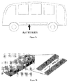
- Fig. 2A shows an outline of a heavy-duty vehicle, such as a bus, with batteries stored within the floor of the vehicle.
- lithium titanate batteries may be mounted within a floor cavity of the vehicle.
- the batteries may be arranged into groupings that may be individually mounted into floor cavities from below or from the sides of the bus floor structure.
- there may be a plurality of cavities below the heavy-duty vehicle which may be separated from one another and may contain one or more grouping of batteries.
- Fig. 2B shows an example of where the batteries may be mounted onto the floor of the heavy- duty vehicle, such as a bus.
- each of the battery packs may fit into a designated area in the floor of the bus.
- the battery system may be designed at a 6.75 inch height or less, which may allow it to fit under the floor of a low-floor transit bus. This may allow for a completely low floor chassis with no compromise in the interior seating layout.
- the bus may have a "true low floor” configuration, such that the bus may have a level floor way throughout the area between the axles of the bus, with energy storage mounted underneath. For example if a bus has two axles, the floor between the two axles may be level and flat between the two axles.
- the battery system may have a height of 8 inches or less, 7.25 inches or less, 7 inches or less, 6.875 inches or less, 6.75 inches or less, 6.625 inches or less, 6.5 inches or less, 6.375 inches or less, 6.25 inches or less, 6 inches or less, five inches or less, four inches or less, or three inches or less.
- each battery pack may have its own compartment within the floor of the bus. In some instances, each battery pack may be physically isolated from the other battery packs. Some of the battery packs may be electrically connected to one another in a string, but may otherwise but electrically isolated from one another.
- the batteries may be integrated into other parts of the heavy-duty vehicle.
- the batteries may be mounted on the front, rear, top, or side of the vehicle.
- the batteries may be distributed over different locations on the vehicle. For example, some of the batteries may be stored within the floor of the vehicle while some of the batteries may be stored on the top of the vehicle. Any combination of battery storage locations may be used.
- the propulsion power source for a heavy-duty vehicle may include one or more battery assembly.
- a battery assembly may provide high voltage power to the traction motor, high power accessories, and low voltage accessories in the vehicle through the use of a converter.
- a large capacity (e.g., 50Ah) cell in a series string of batteries in parallel may be safer to operate in the event of a failure than a parallel set of cells in series. Because lithium cells typically fail-short, if the cell was in parallel with many other cells, the other cells could discharge as much energy as is available into the damaged cell. In some cases, cells may be put in parallel first to reduce cost of battery management systems since each cell voltage may be measured.
- batteries may be arranged in series or parallel, or any combination thereof. Such battery connection flexibility may also allow flexibility in battery placement. Such flexibility of battery placement may be beneficial wherever the batteries are distributed on the vehicle.
- the use of a composite material, or non-burning non-composite material, for the vehicle may allow flexible battery pack placement.
- the height of the batteries may be a constraint.
- the batteries may need to be maintained to less than 6.75" in height. Integrating the battery packs into the floor of a vehicle may keep the center of gravity of the vehicle much lower and balance weight distribution, thus increasing drivability and safety.
- Fig. 2C shows an example of a battery arrangement.
- a module may fit within a battery pack, which may fit within a battery assembly, which may include strings of battery packs connected in series.
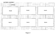
- Fig. 3 shows a high level outline of a battery arrangement, which may be used as a propulsion power source in accordance with one embodiment of the invention.
- the battery assembly in a vehicle may be designed to have any number of main battery strings.
- the battery assembly may include three main battery strings.
- Each string may consist of a number of battery packs.
- Each string may or may not have the same number of packs.
- each string may have two packs.
- one string may have two packs, another string may have one pack, and another string may have five packs.
- the strings may be arranged so that they are connected in parallel. Alternatively, the strings may allow the packs to be connected in series.
- a battery management system may be integrated into the packs and/or modules to give early warning to potential problems with weaker battery cells within a string.
- the BMS can give accurate feedback on cell voltages and temperatures within the modules in order to ensure a healthy battery pack. If there are any problems with a particular string, those modules can be automatically removed from service and the vehicle can operate on reduced capacity until the end of the day if necessary.
- the BMS can disconnect a battery string if a fault is detected. Even if an entire battery string is connected, the vehicle is capable of operating.
- Fig. 4 shows a schematic of a battery assembly that may be used to propel a heavy-duty vehicle, such as a bus, in accordance with one embodiment of the invention.
- the packs may be electrically arranged in a staggered configuration to match cabling resistances and ensure similar operation of each string.
- a staggered configuration is a group of four packs (pack 1, pack 2, pack 3, pack 4 lined up from near to far), that are arranged into two strings.
- the first string may connect pack 1 and pack 4 together, while the second string may connect pack 2 and pack 3 together.
- Each pack may have the same amount of wire connecting the two batteries even if each pack is a different distance from the junction area.
- Each pack may be individually mounted from below the vehicle into one, two, or more cavities built into the floor.
- a pack may include boxes or containers that enclose the contents of the pack.
- the containers may have any shape or configuration that may enable them to hold the contents of the battery pack.
- the containers may be watertight and may be formed of a material that will not oxidize or burn when exposed to an electric arc.
- the material for the containers may be a 3CR12 stainless steel to protect against corrosion from road salts, inhibit oxidation when in contact with an electric arc, and help with material fatigue.
- Other materials, such as composite materials, may be used that may have similar features.
- Fig. 5 shows an example of a battery pack of a string.
- a battery pack may include one or more modules.
- battery packs may each contain eight modules.
- Each battery pack of a battery assembly may or may not include the same number of modules.
- one battery pack may include six modules, while another battery pack may include eight modules, while another battery pack may also include eight modules.
- the pack design may accommodate safety and size.
- a number of factors may be considered including detection, containment, isolation, and suppression.
- Each of these areas may address a group of potential problems that could occur and may help to meet all applicable Federal Motor.
- a BMS may be a primary detection method of a problem with a particular cell, module, pack, or string.
- the BMS may detect when a failure occurs and may be able to direct the battery assembly to disconnect portions of the battery assembly, such as individual battery strings, where the failure may have occurred, in order to prevent other portions of the battery assembly from being compromised and to allow continuous operation of the vehicle.
- the BMS may communicate with and within each pack to achieve the desired level of detection and management.
- the pack may be watertight and may provide containment.
- the pack may be contained within a container or box that may protect the pack from external elements that may damage the contents of the pack.
- the pack container may be designed to protect the pack for a long period of time.
- the container of a pack may contain any failures that may occur within a pack, in order to prevent damage to other packs or portions of the vehicle.
- Dividers between the modules may protect modules from other modules that may have a failure, thus providing isolation. If a module were to fail, the dividers may protect other modules from the failed module.
- the dividers may or may not be integrated into the pack container structure and may be made of a material that may not oxidize when exposed to electrical arcs or high temperatures.
- Fig. 2C shows an example of a pack container with module dividers.
- suppression configurations may be added, which may require providing an exhaust path for the suppression material.
- the exhaust path may consist of an opening drilled in a section of the pack with a spring-return shield and a gasket material to seal the exhaust opening when it is not in use.
- a battery pack may include modules with integrated heat sinks, cooling features such as a cooling plate, module retainers, buss bars to attach modules together, and one or more small compartments that may house the BMS boards, relays, and fuses.
- the compartment may or may not be substantially thermally and/or physically isolated from the modules.
- Interconnection wiring may run to a watertight connector in the small end-box that can disconnect power to the relay, thus making the terminals of the connector safe when the main cable is disconnected.
- the pack may include integrated cooling features in addition to cooling features of the modules.
- integrated cooling plates can provide cooling from a main vehicle electrical cooling system.
- the cooling plates may preferably be maintained below 43 °C for operation of the batteries.
- Other cooling features known in the art, such as various heat sink arrangements or use of convection cooling may be used in a battery pack.
- Active cooling techniques such as fluid cooling, which may utilize fans, the passage of air, liquid, or other fluids, may also be utilized.
- a thermal shield consisting of a spray-on ceramic coating on the lowest point of the packs may be applied to packs exposed to the underside of the vehicle or anywhere else where radiated heat may be a concern.
- Such a battery pack design may have the following benefits: low cost integration, design for safety, ease of assembly, may be maintenance free, and may have simple mounting.
- a battery module may include one or more battery cells.
- the battery cells may be lithium titanate battery cells.
- the battery cells may have other battery chemistries known in the art.
- each module may comprise ten battery cells.
- Each module may or may not include the same number of battery cells. For example, one module may include eight battery cells, while another module may include twelve battery cells, and another module may include thirteen battery cells, while yet another module may include thirteen battery cells.
- the cells may have any arrangement or connection within the module.
- the cells may all be connected in series.
- the cells may be connected in parallel.
- the cells may be connected in a combination of series or parallel within the module.
- the battery cells may have various specifications, such as various voltages.
- each cell for a lithium titanate battery may be at 2.3 Vnominai, 50 Ah giving a nominal energy of 115 Wh.
- Each cell, such as lithium ion batteries or other types of batteries, may or may not vary in its specifications.
- the cells may be prismatic cells.
- Each prismatic cell may be housed in a specialized Mylar/foil pouch and may be somewhat fragile.
- the module housing can be designed to and protect the cells from outside damage, making them easier to handle, and providing cooling support.
- the modules may include cooling features.
- modules may have integrated aluminum cooling fins placed between each cell.
- cooling plates may all link up to an anodized aluminum backplane that can then be cooled to support even cooling through the module.
- Other cooling features known in the art may be used, such as various heat sink arrangements, forced convection cooling, and so forth.
- Fig. 7 shows an example of a module in accordance with one embodiment of the invention.
- the case of a module may be made of an ABS material that can be easily machined and produced very rapidly.
- the case of a module may be of other materials, such as a composite material, fiberglass, or carbon fiber.
- the case may be made from a material that may provide some level of isolation, such as a material that may not burn when exposed to an electric arc.
- a front weld plate can be included to accurately locate and hold the terminals to the case to reduce fatigue stress cracks in the cell tabs.
- the cell tabs may be made of a metal, such as aluminum.
- BMS connectors can be integrated into the front of the module for quick connection of an off-board BMS. Terminals may be offset and tapped for vertical installation of attachment bolts and ease of assembly.
- Modules must be isolated from each other to protect against potential short-circuiting. This can be accomplished through careful material selection and post processing of the heat sinks. If a short is ever detected through the BMS, the system may disconnect each pack in the string, which can isolate the fault. This level of safety may be included in the event of a major crash or failure of the isolation system.
Landscapes
- Engineering & Computer Science (AREA)
- Mechanical Engineering (AREA)
- Chemical & Material Sciences (AREA)
- Transportation (AREA)
- Power Engineering (AREA)
- Electrochemistry (AREA)
- General Chemical & Material Sciences (AREA)
- Chemical Kinetics & Catalysis (AREA)
- Sustainable Energy (AREA)
- Sustainable Development (AREA)
- Life Sciences & Earth Sciences (AREA)
- Combustion & Propulsion (AREA)
- Manufacturing & Machinery (AREA)
- Aviation & Aerospace Engineering (AREA)
- Architecture (AREA)
- Structural Engineering (AREA)
- Inorganic Chemistry (AREA)
- Battery Mounting, Suspending (AREA)
- Electric Propulsion And Braking For Vehicles (AREA)
- Arrangement Or Mounting Of Propulsion Units For Vehicles (AREA)
- Body Structure For Vehicles (AREA)
- Battery Electrode And Active Subsutance (AREA)
Abstract
Description
- This invention was made with the support of the United States government under the National Fuel Cell Bus program, Contract number by the Federal Transit Administration (FTA).
- In recent years, hybrid and electric vehicles, which are provided with a battery, have been proposed, and some of them have been put into practice, to effectively use energy, in particular, regenerative energy as environmental measures. Typically, secondary batteries, which have been put to into practice and installed in vehicles so far, include, for example, lead storage batteries, nickel metal hydride batteries, or high powered lithium ion batteries.
- The use of such batteries provide many challenges such as thermal degradation, or the requirement of significant volumes or space due to low capacity. Such batteries may be heavy, which can lead to decreased performance of vehicles. Furthermore, the active materials of the electrodes are low in the rate of occluding and discharging ions, and hence efficient charging cannot be achieved during fast charging, either form a stationary charger of regenerative charging. The speed of regenerative charging can be very pertinent for a heavy-duty vehicle, such as a bus, that may be regularly recharged within small time frames.
- Thus, a need exists for a heavy-duty vehicle with a battery system capable of rapid charging. A further need exists for a heavy-duty vehicle that can efficiently utilize its battery system.
- The invention is directed to a heavy-duty vehicle, such as a bus, with a power source capable of being fast-charged. In one aspect of the invention, the power source may include a lithium titanate battery source. In some instances, an additional power source may be provided. A power source may comprise one or more battery packs. The power source may be housed in the floor of the heavy-duty vehicle. In some instances, a plurality of battery packs may be individually mounted into cavities within the floor of a vehicle.
- In accordance with another aspect of the invention, the vehicle may have a composite body. The body may be substantially formed from at least one composite material, such as high strength fiber glass or carbon fiber. In some instances, the high stress areas of the vehicle body may be formed from a composite material. Alternatively, the vehicle body may be formed of a lightweight metal or metal alloy.
- One or more battery strings may be provided as a propulsion power source in accordance with an embodiment of the invention. Each string may include one or more battery pack. A battery pack may include one or more module, each of which may include one or more battery cell, such as a lithium titanate battery cell. A battery management system may be integrated at any level of a propulsion power source to provide sensor feedback or any alarms or alerts. The housing for the propulsion power source may include safety features, which may thermally or electrically isolate components.
- Other goals and advantages of the invention will be further appreciated and understood when considered in conjunction with the following description and accompanying drawings. While the following description may contain specific details describing particular embodiments of the invention, this should not be construed as limitations to the scope of the invention but rather as an exemplification of preferable embodiments. For each aspect of the invention, many variations are possible as suggested herein that are known to those of ordinary skill in the art. A variety of changes and modifications can be made within the scope of the invention without departing from the spirit thereof.
- All publications, patents, and patent applications mentioned in this specification are herein incorporated by reference to the same extent as if each individual publication, patent, or patent application was specifically and individually indicated to be incorporated by reference.
- The novel features of the invention are set forth with particularity in the appended claims. A better understanding of the features and advantages of the present invention will be obtained by reference to the following detailed description that sets forth illustrative embodiments, in which the principles of the invention are utilized, and the accompanying drawings:
-
Fig. 1 shows a schematic of a bus with various features in accordance with one embodiment of the invention. -
Fig. 2A shows an outline of a heavy-duty vehicle, such as a bus, with batteries stored within the floor of the vehicle. -
Fig. 2B shows an example of where batteries may be mounted into the floor of a heavy-duty vehicle. -
Fig. 2C shows an example of a battery arrangement. -
Fig. 3 shows a high level outline of a battery arrangement that may be used as a propulsion power source in accordance with one embodiment of the invention. -
Fig. 4 shows a schematic of a battery assembly that may be used to propel a heavy-duty vehicle. -
Fig. 5 shows an example of a battery pack of a string. -
Fig. 6 shows a high-level outline of a battery module. -
Fig. 7 shows an example of a module in accordance with one embodiment of the invention. - The invention provides systems and methods for vehicle batteries. Vehicle battery systems for heavy-duty vehicles or high occupancy vehicles including buses, vans, and class 5-8 trucks, may comprise lithium titanate batteries and may have various arrangements and configurations. Various aspects of the invention described herein may be applied to any of the particular applications set forth below or for any other types of vehicles or power sources. The invention may be applied as a standalone system or method, or as part of an integrated vehicle system. It shall be understood that different aspects of the invention can be appreciated individually, collectively, or in combination with each other.
- Also, various aspects of the invention as described may be combined to provide a heavy-duty hybrid electric vehicle where the battery propulsion power source may deliver 12.5% or greater of the overall vehicle power. In various embodiments, the battery propulsion power source may deliver 15% or greater, 20% or greater, 25% or greater, 30% or greater, 40% or greater, 50% or greater, 70% or greater, 80% or greater, 90% or greater, 95% or greater, or substantially 100% of the overall vehicle power. In one example, features such as a lightweight composite body, efficient drivetrain, and lightweight batteries may be combined such that the battery propulsion power source may deliver a large percentage of the vehicle power requirement.
-
Fig. 1 shows a schematic of a bus with various features, in accordance with one embodiment of the invention. The features of the bus may be applied to other heavy-duty or high occupancy vehicles, wherein "heavy-duty vehicles" may include a transit bus, a school bus, a delivery van, a shuttle bus, a tractor trailer, a class 5 truck (weighing 16,001-19,500 lbs., two-axle, six-tire single unit), a class 6 truck (weighing 19,501-26,000 lbs., three-axle single unit), a class 7 truck (weighing 26,001-33,000 lbs., four or more axle single unit), a class 8 truck (weighing 33,000 lbs. and over, four or less axle single trailer), a vehicle with a GVWR weighing over 14,000 pounds, a vehicle with a cargo to driver mass ratio of 15: 1 or greater, a vehicle with six or more tires, a vehicle with three or more axles, or any other type of high occupancy or heavy-duty vehicle. - A heavy-duty vehicle may have a propulsion power source, which includes batteries. In some embodiments of the invention, the heavy-duty vehicle may have one or more additional power sources, such as a combustion engine or a fuel cell. The heavy-duty vehicle may be an electric battery- powered vehicle or a hybrid electric vehicle, and may be able to use the same basic battery configuration, drive motor, and controller, regardless of whether the vehicle is an all-battery vehicle or a hybrid vehicle.
- In some embodiments, a heavy-duty vehicle may travel a predetermined route, and stop at predetermined points for recharging. See, e.g.,
U.S. Patent No. 3,955,657 , which is hereby incorporated by reference in its entirety. - In one embodiment of the invention, the propulsion power source of a heavy-duty vehicle may include lithium titanate batteries. In some implementations, the propulsion power source may include batteries that are only lithium titanate batteries, without requiring any other types of batteries. The lithium titanate batteries may include any format or composition known in the art. See, e.g.,
U.S. Patent Publication No. 2007/0284159 ,U.S. Patent Publication No. 2005/0132562 ,U.S. Patent Publication No. 2005/0214466 ,U.S. Patent No. 6,890,510 ,U.S. Patent No. 6,974,566 , andU.S. Patent No. 6,881,393 , which are hereby incorporated by reference in their entirety. - The use of lithium titanate batteries may enable rapid charging of a vehicle, and a long battery life. In some embodiments of the invention a battery propulsion power source may be able to charge to a very high state of charge within minutes. For instance, in a preferable embodiment, the power source may be able to charge to over 95% state of charge within ten minutes. In other embodiments of the invention, a battery propulsion power source may be able to charge to over 65% state of charge, over 70% state of charge, over 75% state of charge, over 80% state of charge, over 85% state of charge, over 90% state of charge, or over 95% state of charge within ten minutes, or nine minutes, seven minutes, five minutes, three minutes, or one minute.
- In some implementations, a battery propulsion power source may be charged using a periodic off board charging connection. An off board charging system may be a battery charging system externally located from a vehicle. In an alternate implementation, a battery propulsion power source may be charged by using an on board power generation device. An onboard power generation device may be any power generation device that may be brought onto a vehicle or incorporated into a vehicle, which may incorporate various means to charge a battery.
- In accordance with another embodiment of the invention, the propulsion power source may include batteries with any battery chemistry known in the art or later developed. Such electric or hybrid electric vehicle batteries may include, but are not limited to, lead-acid ("flooded" and VRLA) batteries, NiCad batteries, nickel metal hydride batteries, lithium ion batteries, Li- ion polymer batteries, zinc-air batteries or molten salt batteries. In some implementations, battery storage capacity may be within the 18 to 100 kWh capacity range.
- In some alternate embodiments, the propulsion power source may include a combination of lithium titanate batteries and other types of batteries or ultra capacitors.
- A charge/discharge control circuit may receive measurement signals from sensors of the batteries, such as temperature sensors, voltmeters and ammeters. Based on the input signals the control circuit can compute the present charge capacity, and can set a certain state of charge (SOC), and thereby control the charge/discharge of the batteries of the power source. A battery may receive power from an external or internal power source.
- The battery power source of a heavy-duty vehicle may include an electrode group with a spiral structure formed of a positive electrode, negative electrode and separator between the positive and negative electrode. The electrode group may be formed by winding the positive electrode and negative electrode with the separator, and then subjecting the resultant structure to thermal pressing. Alternatively, the positive electrode, negative electrode and separator may be formed by using an adhesive polymer. A positive terminal can be electrically connected to the positive electrode. Similarly, a band-shaped negative terminal can be electrically connected to the negative electrode. The electrode group may be contained in a container with the ends of the positive and negative terminals made to protrude from the container to form a battery cell.
- The battery may include a negative electrode comprising a negative collector, and a negative- electrode layer provided on one or both sides of the collector and containing a negative electrode active material, conductive agent and binding agent.
- In accordance with some embodiments of the invention, the negative electrode may include an active material with a metal oxide, metal sulfide, metal nitride or metal alloy. In some implementations of the invention, the negative electrode may include active materials for any battery chemistry known in the art.
- A preferable embodiment of the invention may include a negative electrode material containing a lithium titanium complex oxide. Lithium titanate oxides, such as (1) spinel-type Li4+xTi50i2, (x: -1 < x < 3, and preferably, 0<x<1) or (2) ramsdellite-type lithium titanate, such as Li2+xTi307 (x: -1 < x < 3) can be used. Lithium titanium complex oxides may include, in addition to lithium titanium oxides, titanium-based oxides that do not contain lithium.
- Lithium titanium oxides may include, for example, a metal complex oxide containing at least one element selected from the group of Tiθ2, Ti, P, V, Sn, Cu, Ni and Fe. The Tiθ2 may be of an anatase type and may have low crystalline properties acquired at a thermal treatment temperature of 300 to 500 degree C. As a metal complex oxide containing at least one element selected from the group of Ti, P, V, Sn, Cu, Ni and Fe, TiO2-P2O5, TiO2-V2O5, TiO2-P2O5-SnO2, and TiO2-P2O5-MeO (Me is at least one metal selected from the group consisting of Cu, Ni and Fe), etc., can be exemplified. In some cases, the metal complex oxide can have low crystalline properties, and a microstructure in which a crystalline phase and amorphous phase are mixed, or only an amorphous phase exists. By virtue of this microstructure, the cycle performance can be significantly enhanced. In particular, a metal complex oxide containing a lithium titanium oxide and at least one element selected from the group of Ti, P, V, Sn, Cu, Ni and Fe is preferable.
- In some implementations, the average grain size of the primary particles of the negative- electrode material may be 1 m or less. More preferably, the average grain size of the negative-electrode material may be 0.3 m or less.
- A heavy-duty vehicle may include any vehicle body composition and structure known in the art. In some cases, a high occupancy or heavy-duty vehicle may have a body structure that may classify it as, for example, a transit bus, a school bus, a delivery van, a shuttle bus, a tractor trailer, or class 5-8 truck.
- For example, a heavy-duty vehicle may have a body composed of a metal such as aluminum or steel, or alloys such as a magnesium alloy. In preferable embodiments of the invention, the vehicle may have a lightweight, strong body.
- The heavy-duty vehicle may also include a vehicle body including at least one composite material. In some embodiments of the invention, the heavy-duty vehicle body may be substantially formed from at least one composite material. A composite material is preferably a lightweight, non- metallic material. For example, high stress areas of the vehicle may be formed of a composite material such as carbon fiber, balsa and/or structural foam core. In some examples, the bulk of the body may be formed of a high strength fiberglass, balsa and/or foam core.
- Several alternate embodiments of the invention may include a vehicle body where the body comprises a first skin, a second skin, and a core between the skins. For example, the core may comprise a honeycomb structure, or may be constructed from balsa wood or foam, or may include a composite material that is or is not the same as the first or second skin materials. Other materials that may form various parts of the vehicle body may include aluminum, stainless steel, fiberglass, aramid, ultra high molecular weight polyethylene, carbon fiber, or other known structural fibers, fiber reinforced plastics or combination thereof. Other combinations of composite materials may be used for various components of the heavy-duty vehicle.
- Composites may include materials that may cover a wide range of strength, from low-grade non- structural materials using short fibers or non-oriented fibers with inexpensive resins, to high strength and stiffness properties utilizing woven cloth in a high performance resin system. Body panels may be structural elements, which have high strength, and a preferred embodiment may utilize this type of construction. The common materials for structural composites in commercial applications may include fiberglass, aramid, and carbon fiber cloths and tapes in a vinyl ester or epoxy resin matrix. These materials may have different mechanical properties in terms of tensile strength and stiffness, compressive strength and stiffness, impact resistance, etc. The composite materials can also be corrosion and moisture-resistant when properly constructed.
- By utilizing selected combinations of these materials with these individual properties, the vehicle body can achieve the desired performance characteristics of extremely high strength in the plane of the panel or at a right angle, high stiffness, and good impact strength and durability. In some embodiments, the materials may include non-composite materials, composite materials, or a combination thereof. Proper design and construction of these structural composite panels may provide all the necessary strength and stiffness to serve as the sole self-supporting structure of the vehicle chassis, even for intensive urban service.
- In some embodiments, the vehicle structure may include a lightweight skeletal frame with a plurality of body panels attached to the skeletal frame. In another embodiment, the body may be molded out of several pieces or one piece.
- In accordance with one embodiment of the invention, the floor structure of the vehicle may be substantially formed from at least one composite material. For example, the floor structure of the vehicle may be substantially formed from carbon fiber or fiberglass. Alternatively, the floor structure may be formed of a non-composite material such as a metal, which may include aluminum or steel. The floor structure may be formed of any material that may not burn when exposed to an electric arc, or relatively high heat.
-
Fig. 2A shows an outline of a heavy-duty vehicle, such as a bus, with batteries stored within the floor of the vehicle. In accordance with some embodiments of the invention, lithium titanate batteries may be mounted within a floor cavity of the vehicle. The batteries may be arranged into groupings that may be individually mounted into floor cavities from below or from the sides of the bus floor structure. In some embodiments of the invention, there may be a plurality of cavities below the heavy-duty vehicle, which may be separated from one another and may contain one or more grouping of batteries. Alternatively, there may be one cavity below the vehicle, which may contain the groupings of batteries. -
Fig. 2B shows an example of where the batteries may be mounted onto the floor of the heavy- duty vehicle, such as a bus. For example, each of the battery packs may fit into a designated area in the floor of the bus. The battery system may be designed at a 6.75 inch height or less, which may allow it to fit under the floor of a low-floor transit bus. This may allow for a completely low floor chassis with no compromise in the interior seating layout. The bus may have a "true low floor" configuration, such that the bus may have a level floor way throughout the area between the axles of the bus, with energy storage mounted underneath. For example if a bus has two axles, the floor between the two axles may be level and flat between the two axles. This may also apply to heavy duty vehicles with two or more axles; the floor between any of the axles may be level and flat. This may indicate that the floor of the bus may not have protrusions to accommodate the underlying batteries; the batteries may lie flat beneath the floor of the bus. This may contrast with traditional buses, which have boxes underneath passenger seats for the energy storage system, which comprises seating layouts. The battery system may have a height of 8 inches or less, 7.25 inches or less, 7 inches or less, 6.875 inches or less, 6.75 inches or less, 6.625 inches or less, 6.5 inches or less, 6.375 inches or less, 6.25 inches or less, 6 inches or less, five inches or less, four inches or less, or three inches or less. - In some embodiments, each battery pack may have its own compartment within the floor of the bus. In some instances, each battery pack may be physically isolated from the other battery packs. Some of the battery packs may be electrically connected to one another in a string, but may otherwise but electrically isolated from one another.
- In alternate embodiments of the invention, the batteries may be integrated into other parts of the heavy-duty vehicle. For example, the batteries may be mounted on the front, rear, top, or side of the vehicle. In some implementations, the batteries may be distributed over different locations on the vehicle. For example, some of the batteries may be stored within the floor of the vehicle while some of the batteries may be stored on the top of the vehicle. Any combination of battery storage locations may be used.
- The propulsion power source for a heavy-duty vehicle may include one or more battery assembly. A battery assembly may provide high voltage power to the traction motor, high power accessories, and low voltage accessories in the vehicle through the use of a converter. In one implementation of the invention, a large capacity (e.g., 50Ah) cell in a series string of batteries in parallel may be safer to operate in the event of a failure than a parallel set of cells in series. Because lithium cells typically fail-short, if the cell was in parallel with many other cells, the other cells could discharge as much energy as is available into the damaged cell. In some cases, cells may be put in parallel first to reduce cost of battery management systems since each cell voltage may be measured. However, in some other embodiments, with larger capacity cells, paralleling batteries before placing them in series may not be necessary. The use of larger capacity cells may increase the safety of the entire assembly without adding cost to the battery management system. Thus, batteries may be arranged in series or parallel, or any combination thereof. Such battery connection flexibility may also allow flexibility in battery placement. Such flexibility of battery placement may be beneficial wherever the batteries are distributed on the vehicle.
- In addition, the use of a composite material, or non-burning non-composite material, for the vehicle may allow flexible battery pack placement. In the event of a low- floor design of a heavy-duty vehicle, the height of the batteries may be a constraint. For example, in some embodiments, such as a low floor transit or school bus, the batteries may need to be maintained to less than 6.75" in height. Integrating the battery packs into the floor of a vehicle may keep the center of gravity of the vehicle much lower and balance weight distribution, thus increasing drivability and safety.
-
Fig. 2C shows an example of a battery arrangement. A module may fit within a battery pack, which may fit within a battery assembly, which may include strings of battery packs connected in series. -
Fig. 3 shows a high level outline of a battery arrangement, which may be used as a propulsion power source in accordance with one embodiment of the invention. The battery assembly in a vehicle may be designed to have any number of main battery strings. For example, in embodiment, the battery assembly may include three main battery strings. Each string may consist of a number of battery packs. For example, there may be two packs per string. Each string may or may not have the same number of packs. For example, each string may have two packs. In another example, one string may have two packs, another string may have one pack, and another string may have five packs. The strings may be arranged so that they are connected in parallel. Alternatively, the strings may allow the packs to be connected in series. - A battery management system (BMS) may be integrated into the packs and/or modules to give early warning to potential problems with weaker battery cells within a string. The BMS can give accurate feedback on cell voltages and temperatures within the modules in order to ensure a healthy battery pack. If there are any problems with a particular string, those modules can be automatically removed from service and the vehicle can operate on reduced capacity until the end of the day if necessary. The BMS can disconnect a battery string if a fault is detected. Even if an entire battery string is connected, the vehicle is capable of operating.
-
Fig. 4 shows a schematic of a battery assembly that may be used to propel a heavy-duty vehicle, such as a bus, in accordance with one embodiment of the invention. In some cases, the packs may be electrically arranged in a staggered configuration to match cabling resistances and ensure similar operation of each string. One example of a staggered configuration is a group of four packs (pack 1, pack 2, pack 3, pack 4 lined up from near to far), that are arranged into two strings. The first string may connect pack 1 and pack 4 together, while the second string may connect pack 2 and pack 3 together. Each pack may have the same amount of wire connecting the two batteries even if each pack is a different distance from the junction area. Each pack may be individually mounted from below the vehicle into one, two, or more cavities built into the floor. - A pack may include boxes or containers that enclose the contents of the pack. The containers may have any shape or configuration that may enable them to hold the contents of the battery pack. The containers may be watertight and may be formed of a material that will not oxidize or burn when exposed to an electric arc. For example, the material for the containers may be a 3CR12 stainless steel to protect against corrosion from road salts, inhibit oxidation when in contact with an electric arc, and help with material fatigue. Other materials, such as composite materials, may be used that may have similar features.
-
Fig. 5 shows an example of a battery pack of a string. A battery pack may include one or more modules. For example, battery packs may each contain eight modules. Each battery pack of a battery assembly may or may not include the same number of modules. For example, one battery pack may include six modules, while another battery pack may include eight modules, while another battery pack may also include eight modules. - The pack design may accommodate safety and size. In a pack design, a number of factors may be considered including detection, containment, isolation, and suppression. Each of these areas may address a group of potential problems that could occur and may help to meet all applicable Federal Motor.
- A BMS may be a primary detection method of a problem with a particular cell, module, pack, or string. The BMS may detect when a failure occurs and may be able to direct the battery assembly to disconnect portions of the battery assembly, such as individual battery strings, where the failure may have occurred, in order to prevent other portions of the battery assembly from being compromised and to allow continuous operation of the vehicle. The BMS may communicate with and within each pack to achieve the desired level of detection and management.
- The pack may be watertight and may provide containment. The pack may be contained within a container or box that may protect the pack from external elements that may damage the contents of the pack. The pack container may be designed to protect the pack for a long period of time. In addition to protecting the contents of the pack from external threats, the container of a pack may contain any failures that may occur within a pack, in order to prevent damage to other packs or portions of the vehicle.
- Dividers between the modules may protect modules from other modules that may have a failure, thus providing isolation. If a module were to fail, the dividers may protect other modules from the failed module. The dividers may or may not be integrated into the pack container structure and may be made of a material that may not oxidize when exposed to electrical arcs or high temperatures.
Fig. 2C shows an example of a pack container with module dividers. - Suppression may not necessary due to the very limited airspace within the enclosure. In some cases, suppression configurations may be added, which may require providing an exhaust path for the suppression material. The exhaust path may consist of an opening drilled in a section of the pack with a spring-return shield and a gasket material to seal the exhaust opening when it is not in use.
- In some embodiments, a battery pack may include modules with integrated heat sinks, cooling features such as a cooling plate, module retainers, buss bars to attach modules together, and one or more small compartments that may house the BMS boards, relays, and fuses. The compartment may or may not be substantially thermally and/or physically isolated from the modules. Interconnection wiring may run to a watertight connector in the small end-box that can disconnect power to the relay, thus making the terminals of the connector safe when the main cable is disconnected. The pack may include integrated cooling features in addition to cooling features of the modules. In some implementations, integrated cooling plates can provide cooling from a main vehicle electrical cooling system. In some embodiments, the cooling plates may preferably be maintained below 43 °C for operation of the batteries. Other cooling features known in the art, such as various heat sink arrangements or use of convection cooling may be used in a battery pack. Active cooling techniques, such as fluid cooling, which may utilize fans, the passage of air, liquid, or other fluids, may also be utilized.
- A thermal shield consisting of a spray-on ceramic coating on the lowest point of the packs may be applied to packs exposed to the underside of the vehicle or anywhere else where radiated heat may be a concern.
- Such a battery pack design may have the following benefits: low cost integration, design for safety, ease of assembly, may be maintenance free, and may have simple mounting.
-
Fig. 6 shows a high-level outline of a battery module. A battery module may include one or more battery cells. In a preferable embodiment, the battery cells may be lithium titanate battery cells. In other embodiments, the battery cells may have other battery chemistries known in the art. For example, each module may comprise ten battery cells. Each module may or may not include the same number of battery cells. For example, one module may include eight battery cells, while another module may include twelve battery cells, and another module may include thirteen battery cells, while yet another module may include thirteen battery cells. - The cells may have any arrangement or connection within the module. For example, the cells may all be connected in series. Alternatively, the cells may be connected in parallel. Or in some cases, the cells may be connected in a combination of series or parallel within the module.
- The battery cells may have various specifications, such as various voltages. For example, each cell for a lithium titanate battery may be at 2.3 Vnominai, 50 Ah giving a nominal energy of 115 Wh. Each cell, such as lithium ion batteries or other types of batteries, may or may not vary in its specifications. In some embodiments, the cells may be prismatic cells. Each prismatic cell may be housed in a specialized Mylar/foil pouch and may be somewhat fragile. The module housing can be designed to and protect the cells from outside damage, making them easier to handle, and providing cooling support.
- The modules may include cooling features. For example, modules may have integrated aluminum cooling fins placed between each cell. In other examples, cooling plates may all link up to an anodized aluminum backplane that can then be cooled to support even cooling through the module. Other cooling features known in the art may be used, such as various heat sink arrangements, forced convection cooling, and so forth.
-
Fig. 7 shows an example of a module in accordance with one embodiment of the invention. The case of a module may be made of an ABS material that can be easily machined and produced very rapidly. In other implementations, the case of a module may be of other materials, such as a composite material, fiberglass, or carbon fiber. In some examples, the case may be made from a material that may provide some level of isolation, such as a material that may not burn when exposed to an electric arc. A front weld plate can be included to accurately locate and hold the terminals to the case to reduce fatigue stress cracks in the cell tabs. In some cases, the cell tabs may be made of a metal, such as aluminum. BMS connectors can be integrated into the front of the module for quick connection of an off-board BMS. Terminals may be offset and tapped for vertical installation of attachment bolts and ease of assembly. - Modules must be isolated from each other to protect against potential short-circuiting. This can be accomplished through careful material selection and post processing of the heat sinks. If a short is ever detected through the BMS, the system may disconnect each pack in the string, which can isolate the fault. This level of safety may be included in the event of a major crash or failure of the isolation system.
- It should be understood from the foregoing that, while particular implementations have been illustrated and described, various modifications can be made thereto and are contemplated herein. It is also not intended that the invention be limited by the specific examples provided within the specification. While the invention has been described with reference to the aforementioned specification, the descriptions and illustrations of the preferable embodiments herein are not meant to be construed in a limiting sense. Furthermore, it shall be understood that all aspects of the invention are not limited to the specific depictions, configurations or relative proportions set forth herein which depend upon a variety of conditions and variables. Various modifications in form and detail of the embodiments of the invention will be apparent to a person skilled in the art. It is therefore contemplated that the invention shall also cover any such modifications, variations and equivalents.
- Aspects of the subject matter described herein are set out in the following numbered clauses:
- 1. A heavy-duty vehicle comprising: a lithium titanate battery power source, wherein the lithium titanate battery power source includes a plurality of battery packs and is housed within a floor structure of the heavy-duty vehicle such that individual battery packs are individually mounted into cavities within the floor structure.
- 2. The vehicle of clause 1 wherein the floor structure of the heavy-duty vehicle is substantially formed from at least one composite material.
- 3. The vehicle of clause 1 wherein the lithium titanate battery power source includes at least one battery assembly with a plurality of battery strings, wherein a battery string includes a plurality of battery packs, wherein a battery pack includes a plurality of battery modules, wherein a battery module includes a plurality of lithium titanate cells.
- 4. The vehicle of clause 3 wherein a battery pack includes a watertight box made from stainless steel or a composite material that will not oxidize when exposed to an electric arc.
- 5. The vehicle of clause 3 wherein a battery pack includes dividers that provide isolation between the plurality of battery modules.
- 6. The vehicle of clause 3 wherein a battery pack and a battery module have integrated cooling features.
- 7. The vehicle of clause 3 further comprising a battery management system capable of disconnecting a battery string if a fault is detected.
- 8. The vehicle of clause 3 wherein the heavy-duty vehicle is capable of operating if a battery string is disconnected.
- 9. The vehicle of clause 1 wherein a heavy-duty vehicle is one of the following: a transit bus, a school bus, a package delivery van, a shuttle bus, class 5-8 truck, or a tractor trailer.
- 10. The vehicle of clause 1 wherein the floor of the heavy-duty vehicle is a level floor between axles of the vehicle.
- 11. The vehicle of clause 1 wherein the lithium titanate battery power source has a height of 6.75 inches or less.
- 12. A heavy-duty vehicle comprising: a lithium titanate battery propulsion power source; and a vehicle body substantially formed from at least one composite material that houses the lithium titanate battery propulsion power source.
- 13. The heavy-duty vehicle of clause 12 wherein the high stress areas of the vehicle body are formed from carbon fiber.
- 14. The heavy-duty vehicle of clause 12 wherein the heavy-duty vehicle further comprises at least one additional propulsion power source.
- 15. A heavy-duty vehicle comprising a battery propulsion power source, wherein the battery propulsion power source includes at least one battery assembly with a plurality of battery strings, wherein a battery string includes a plurality of battery packs, wherein a battery pack includes a plurality of battery modules, wherein a battery module includes a plurality of battery cells.
- 16. The heavy-duty hybrid electric vehicle of clause 15, wherein the battery propulsion power source is able to provide 12.5% or greater of the overall vehicle power.
- 17. The heavy-duty hybrid electric vehicle of clause 15, wherein the battery propulsion power source is capable of charging to 90% or more of the overall battery capacity within ten minutes using a periodic off board charging connection.
- 18. The heavy-duty hybrid electric vehicle of clause 15, wherein the battery propulsion power source is capable of charging to 90% or more of the overall battery capacity within ten minutes using an on board power generation device.
- 19. A heavy-duty vehicle comprising a battery propulsion power source comprising batteries that are solely lithium titanate batteries.
Claims (11)
- A low-floor electric bus comprising:a body;a floor; anda plurality of battery packs mounted under the floor of the low-floor electric bus.
- The low-floor electric bus of claim 1, wherein the plurality of battery packs are mounted under the floor such that the floor inside the bus in an area that extends substantially an entire width of the bus between a front axle and a rear axle of the bus is substantially flat.
- The low-floor electric bus of claim 1, wherein each battery pack of the plurality of packs has a height of 8 inches or less.
- The low-floor electric bus of claim 1, wherein each battery pack of the plurality of battery packs has a height of 6.75 inches or less.
- The low-floor electric bus of claim 1, wherein the body includes a composite material and the floor includes a composite material.
- The low-floor electric bus of claim 5, wherein the composite material of the body comprises a first skin and a second skin with a core sandwiched between the first and the second skins.
- The low-floor electric bus of claim 6, wherein the first and the second skins include fiber glass and the core includes balsa wood.
- The low-floor electric bus of claim 1, wherein each battery pack of the plurality of battery packs is positioned in a cavity under the floor.
- The low-floor electric bus of claim 1, wherein the plurality of battery packs includes multiple lithium titanate battery packs.
- The low-floor electric bus of claim 9, wherein the plurality of battery packs include at least one battery pack having a chemistry different from the multiple lithium titanate battery packs.
- The low-floor electric bus of claim 1, wherein the plurality of battery packs are configured to be charged to over 90% state of charge in ten minutes.
Applications Claiming Priority (3)
| Application Number | Priority Date | Filing Date | Title |
|---|---|---|---|
| US7648008P | 2008-06-27 | 2008-06-27 | |
| PCT/US2009/048952 WO2009158674A2 (en) | 2008-06-27 | 2009-06-26 | Vehicle battery systems and methods |
| EP09771205.3A EP2307218B1 (en) | 2008-06-27 | 2009-06-26 | Vehicle battery systems and methods |
Related Parent Applications (1)
| Application Number | Title | Priority Date | Filing Date |
|---|---|---|---|
| EP09771205.3A Division EP2307218B1 (en) | 2008-06-27 | 2009-06-26 | Vehicle battery systems and methods |
Publications (3)
| Publication Number | Publication Date |
|---|---|
| EP3017986A2 true EP3017986A2 (en) | 2016-05-11 |
| EP3017986A3 EP3017986A3 (en) | 2017-09-06 |
| EP3017986B1 EP3017986B1 (en) | 2022-11-09 |
Family
ID=41445369
Family Applications (2)
| Application Number | Title | Priority Date | Filing Date |
|---|---|---|---|
| EP09771205.3A Active EP2307218B1 (en) | 2008-06-27 | 2009-06-26 | Vehicle battery systems and methods |
| EP15183066.8A Active EP3017986B1 (en) | 2008-06-27 | 2009-06-26 | Vehicle battery systems and method |
Family Applications Before (1)
| Application Number | Title | Priority Date | Filing Date |
|---|---|---|---|
| EP09771205.3A Active EP2307218B1 (en) | 2008-06-27 | 2009-06-26 | Vehicle battery systems and methods |
Country Status (13)
| Country | Link |
|---|---|
| US (7) | US8453773B2 (en) |
| EP (2) | EP2307218B1 (en) |
| JP (1) | JP2011526228A (en) |
| KR (1) | KR20110039541A (en) |
| CN (1) | CN102105319A (en) |
| AU (1) | AU2009261982B2 (en) |
| CA (1) | CA2728679C (en) |
| CL (1) | CL2010001545A1 (en) |
| CO (1) | CO6341595A2 (en) |
| IL (1) | IL210180A0 (en) |
| MX (1) | MX2010014560A (en) |
| PE (1) | PE20110470A1 (en) |
| WO (1) | WO2009158674A2 (en) |
Cited By (1)
| Publication number | Priority date | Publication date | Assignee | Title |
|---|---|---|---|---|
| EP3896756A4 (en) * | 2019-01-11 | 2022-10-12 | Wang, Ninghao | Quick-change general power battery for new energy vehicles |
Families Citing this family (110)
| Publication number | Priority date | Publication date | Assignee | Title |
|---|---|---|---|---|
| EP2307218B1 (en) | 2008-06-27 | 2015-09-30 | Proterra Inc. | Vehicle battery systems and methods |
| WO2010053872A1 (en) * | 2008-11-05 | 2010-05-14 | Greensmith Energy Management Systems, Llc | Distributed energy storage system, and applications thereof |
| DE102009018787A1 (en) * | 2009-04-24 | 2010-10-28 | Akasol Engineering Gmbh | battery module |
| US8256553B2 (en) * | 2010-02-17 | 2012-09-04 | Roberto De Paschoal | Electric vehicles |
| US8895168B2 (en) * | 2010-03-02 | 2014-11-25 | Lenovo (Singapore) Pte. Ltd. | Deactivating a power source |
| US8820444B2 (en) * | 2010-04-16 | 2014-09-02 | Tuan Nguyen | Electric vehicle having exchangeable battery modules and method of resupply therefor |
| TW201230590A (en) | 2010-04-26 | 2012-07-16 | Proterra Inc | Systems and methods for automatic connection and charging of an electric vehicle at a charging station |
| FR2962376B1 (en) * | 2010-07-07 | 2012-07-20 | Peugeot Citroen Automobiles Sa | DISPOSITION OF FEEDING BODIES |
| US8728651B2 (en) | 2010-08-30 | 2014-05-20 | Highwater Innovations, Llc | Low aspect ratio spiral-wound VRLA battery |
| BR112013007078A2 (en) | 2010-09-21 | 2019-09-24 | Proterra Inc | energy storage system and charging methods |
| JP2012119249A (en) * | 2010-12-03 | 2012-06-21 | Hitachi Maxell Energy Ltd | Battery pack and battery module |
| KR20120062956A (en) * | 2010-12-07 | 2012-06-15 | 현대자동차주식회사 | High voltage system of electric vehicles |
| US8875828B2 (en) | 2010-12-22 | 2014-11-04 | Tesla Motors, Inc. | Vehicle battery pack thermal barrier |
| US8702161B2 (en) | 2010-12-22 | 2014-04-22 | Tesla Motors, Inc. | System for absorbing and distributing side impact energy utilizing an integrated battery pack and side sill assembly |
| US20120161472A1 (en) | 2010-12-22 | 2012-06-28 | Tesla Motors, Inc. | System for Absorbing and Distributing Side Impact Energy Utilizing an Integrated Battery Pack |
| US8833499B2 (en) * | 2010-12-22 | 2014-09-16 | Tesla Motors, Inc. | Integration system for a vehicle battery pack |
| WO2012123815A1 (en) | 2011-03-17 | 2012-09-20 | Ev Chip Energy Ltd. | Battery pack system |
| DE102011108231A1 (en) * | 2011-04-12 | 2012-10-18 | Audi Ag | Energiespeicheranordung |
| DE102011076981B4 (en) * | 2011-06-06 | 2021-08-26 | Robert Bosch Gmbh | Battery system, motor vehicle with this battery system and method for producing operational readiness in a motor vehicle with this battery system |
| CN202138210U (en) * | 2011-06-28 | 2012-02-08 | 比亚迪股份有限公司 | Electric bus |
| KR101283602B1 (en) | 2011-12-08 | 2013-07-05 | 현대자동차주식회사 | Charging network system for electric vehicle |
| US8945749B2 (en) * | 2011-12-15 | 2015-02-03 | GM Global Technology Operations LLC | Carbon fiber thermal interface for cooling module assembly |
| FR2986190B1 (en) | 2012-02-01 | 2015-02-27 | Plastic Omnium Cie | CASE FOR ELECTRICAL MODULE OF A BATTERY PACK FOR MOTOR VEHICLE AND BATTERY PACK FOR MOTOR VEHICLE |
| CN102700423A (en) * | 2012-02-28 | 2012-10-03 | 付长发 | Double-end-power pure electric coach |
| JP5970870B2 (en) * | 2012-03-06 | 2016-08-17 | スズキ株式会社 | Electric parts mounting structure for hybrid vehicle |
| US20130302668A1 (en) * | 2012-04-18 | 2013-11-14 | Lg Chem, Ltd. | Electrolyte for secondary battery and the secondary battery comprising the same |
| US9718367B2 (en) | 2012-08-30 | 2017-08-01 | Proterra Inc. | Side-facing vehicle charging system |
| CA2890753C (en) | 2012-11-13 | 2021-06-22 | Proterra Inc. | Systems and methods for enabling fast charging of an electric vehicle at a charging station |
| GB2512926B (en) * | 2013-04-12 | 2015-08-05 | Univ Dublin City | Electric dumper vehicle |
| KR20160023800A (en) * | 2013-07-24 | 2016-03-03 | 알리스 에코 에이알케이 코. 엘티디. | Detachable high-voltage isolation structure of medium-sized electric vehicle |
| US9812732B2 (en) * | 2013-08-16 | 2017-11-07 | Johnson Controls Technology Company | Dual storage system and method with lithium ion and lead acid battery cells |
| JP6119529B2 (en) * | 2013-09-25 | 2017-04-26 | 株式会社デンソー | Battery system |
| EP2965935B1 (en) * | 2014-06-17 | 2017-10-04 | FERRARI S.p.A. | Electric power system of a vehicle with electric propulsion |
| US10017068B2 (en) | 2014-06-19 | 2018-07-10 | Proterra Inc. | Charging of a fleet of electric vehicles |
| PT3176022T (en) * | 2014-07-30 | 2022-02-24 | Creatio Irizar Group Innovation Center Aie | Bus |
| JP6438266B2 (en) * | 2014-10-20 | 2018-12-12 | 日立建機株式会社 | Dump truck |
| CN104553719A (en) * | 2014-12-29 | 2015-04-29 | 金龙联合汽车工业(苏州)有限公司 | Directly-connected driving pure electric passenger car for groups |
| DE102015003643B3 (en) * | 2015-03-19 | 2016-06-16 | Audi Ag | motor vehicle |
| US10377251B2 (en) | 2015-03-26 | 2019-08-13 | Proterra Inc. | Electric vehicle charging interface |
| US9423465B1 (en) | 2015-06-30 | 2016-08-23 | Proterra Inc. | State of charge determination |
| US9321355B1 (en) | 2015-06-30 | 2016-04-26 | Proterra Inc. | Controlling electric vehicle operation based on inclination |
| US20170005377A1 (en) * | 2015-06-30 | 2017-01-05 | Faraday&Future Inc. | Battery Pack for Vehicle Energy-Storage Systems |
| US9321364B1 (en) | 2015-06-30 | 2016-04-26 | Proterra Inc. | Heated charging interface of electric vehicle |
| US9905893B2 (en) | 2015-06-30 | 2018-02-27 | Proterra Inc. | Battery system cooling |
| US10040370B2 (en) * | 2015-09-19 | 2018-08-07 | Ningbo Wise Digital Technology Co., Ltd | Container comprising a battery, transportation system comprising the same and method thereof |
| US11296370B2 (en) * | 2015-12-03 | 2022-04-05 | Eaglepicher Technologies, Llc | Battery having high thermal conductivity case |
| US11214157B2 (en) | 2015-12-30 | 2022-01-04 | Proterra Inc. | Electric vehicle charging to reduce utility cost |
| GB2550601B (en) * | 2016-05-24 | 2019-06-12 | Sevcon Ltd | Methods and apparatus for the provision of AC power |
| US9764658B1 (en) | 2016-06-21 | 2017-09-19 | Proterra Inc. | Electric motor control by torque perturbation |
| KR102645090B1 (en) * | 2016-07-07 | 2024-03-07 | 삼성전자주식회사 | Unit cell, and preparation method thereof |
| DE102016213262A1 (en) * | 2016-07-20 | 2018-01-25 | Bayerische Motoren Werke Aktiengesellschaft | motor vehicle |
| US10632857B2 (en) | 2016-08-17 | 2020-04-28 | Shape Corp. | Battery support and protection structure for a vehicle |
| US10160492B2 (en) * | 2016-10-14 | 2018-12-25 | Inevit Llc | Battery junction box housing configured to direct crash forces in an electric vehicle |
| US10574365B2 (en) * | 2016-10-14 | 2020-02-25 | Tiveni Mergeco, Inc. | Optical communications interface for battery modules of an energy storage system |
| US20180105062A1 (en) * | 2016-10-14 | 2018-04-19 | Inevit, Inc. | Battery module compartment chamber and battery module mounting area of an energy storage system and method thereof |
| US10272758B2 (en) | 2016-11-02 | 2019-04-30 | Proterra Inc. | Battery system of an electric vehicle |
| CN108237885B (en) * | 2016-12-26 | 2022-03-08 | 上海同捷科技股份有限公司 | Automobile battery supporting plate assembly structure |
| WO2018127832A1 (en) | 2017-01-04 | 2018-07-12 | Shape Corp. | Vehicle battery tray structure with nodal modularity |
| CN106672085A (en) * | 2017-01-16 | 2017-05-17 | 四川省客车制造有限责任公司 | High-capacity flat bottom floor and automobile with same |
| DE102017203519B4 (en) | 2017-03-03 | 2024-02-15 | Audi Ag | Battery arrangement for a motor vehicle and motor vehicle |
| US10483510B2 (en) | 2017-05-16 | 2019-11-19 | Shape Corp. | Polarized battery tray for a vehicle |
| US10886513B2 (en) | 2017-05-16 | 2021-01-05 | Shape Corp. | Vehicle battery tray having tub-based integration |
| US11211656B2 (en) | 2017-05-16 | 2021-12-28 | Shape Corp. | Vehicle battery tray with integrated battery retention and support feature |
| US10272899B2 (en) | 2017-08-01 | 2019-04-30 | Proterra Inc. | Controlling the powertrain of a vehicle |
| ES2966609T3 (en) * | 2017-09-01 | 2024-04-23 | Massachusetts Inst Technology | Surface Penetrating Radar and Battery Systems |
| US11088412B2 (en) | 2017-09-13 | 2021-08-10 | Shape Corp. | Vehicle battery tray with tubular peripheral wall |
| US11027624B2 (en) | 2017-09-15 | 2021-06-08 | Proterra Inc. | Electric vehicle charging by adjusting charger current based on battery chemistry |
| US10661646B2 (en) | 2017-10-04 | 2020-05-26 | Shape Corp. | Battery tray floor assembly for electric vehicles |
| CA3019673A1 (en) | 2017-10-06 | 2019-04-06 | Proterra Inc. | Controlling the powertrain of a vehicle |
| TWI676315B (en) * | 2017-10-20 | 2019-11-01 | 輝能科技股份有限公司 | Composite battery cell |
| DE102017011994B3 (en) | 2017-12-22 | 2019-01-10 | Daimler Ag | Energy storage unit for a motor vehicle, mounting arrangement of such an energy storage unit on a structure of a motor vehicle, and motor vehicle with such an energy storage unit |
| WO2019169080A1 (en) | 2018-03-01 | 2019-09-06 | Shape Corp. | Cooling system integrated with vehicle battery tray |
| US11688910B2 (en) | 2018-03-15 | 2023-06-27 | Shape Corp. | Vehicle battery tray having tub-based component |
| US11362379B2 (en) | 2018-03-15 | 2022-06-14 | Carrier Corporation | Transportation refrigeration unit with integrated battery enclosure cooling |
| CN112088455A (en) | 2018-03-19 | 2020-12-15 | 埃夫奇普能源有限责任公司 | Power pack and power pack circuit |
| US10811869B2 (en) | 2018-04-17 | 2020-10-20 | Proterra, Inc. | Overcurrent protection for battery systems |
| JP7070237B2 (en) * | 2018-08-21 | 2022-05-18 | トヨタ自動車株式会社 | Electric car |
| DE102018121220A1 (en) * | 2018-08-30 | 2020-03-05 | Man Truck & Bus Se | Energy module for a commercial vehicle |
| DE102018216050A1 (en) | 2018-09-20 | 2020-03-26 | Robert Bosch Gmbh | Traction battery in a vehicle |
| CN109532519A (en) * | 2018-09-28 | 2019-03-29 | 北京长城华冠汽车科技股份有限公司 | The cell system design method and device of electric car |
| US20220109216A1 (en) * | 2018-10-01 | 2022-04-07 | Honda Motor Co., Ltd. | Battery module and battery pack |
| US10744899B2 (en) | 2018-10-24 | 2020-08-18 | Proterra Inc. | Balancing energy in a parallelized battery system |
| US11865909B2 (en) * | 2018-10-26 | 2024-01-09 | Qingdao United New Energy Automobile Co., Ltd. | Electric car provided with battery compartment |
| EP3699441B1 (en) | 2019-02-21 | 2024-05-01 | Ebusco B.V. | Assembly of a first and second panel |
| US10690234B1 (en) | 2019-03-14 | 2020-06-23 | Proterra Inc. | Electric vehicle powertrain |
| US11214115B2 (en) | 2019-06-03 | 2022-01-04 | Proterra Inc. | Temperature management systems and methods for electric vehicle |
| JP7136021B2 (en) | 2019-06-28 | 2022-09-13 | トヨタ自動車株式会社 | electric vehicle |
| USD949051S1 (en) * | 2019-07-11 | 2022-04-19 | Jaguar Land Rover Limited | Vehicle |
| WO2021061516A1 (en) * | 2019-09-23 | 2021-04-01 | Mitsubishi Chemical America, Inc. | Heat resistant fiber layer for battery insulation |
| US12037048B2 (en) | 2019-10-17 | 2024-07-16 | Letenda Inc. | Modular low floor bus |
| US11964535B2 (en) * | 2019-11-18 | 2024-04-23 | Bollinger Motors, Inc. | Electric automotive vehicle |
| US11374284B2 (en) | 2019-12-13 | 2022-06-28 | Proterra Operating Company, Inc. | Battery vent system |
| US11400982B2 (en) | 2020-01-06 | 2022-08-02 | Workhorse Group Inc. | Methods of making monocoques of land vehicles using modular mold systems |
| US11472485B2 (en) | 2020-01-06 | 2022-10-18 | Workhorse Group Inc. | Land vehicles incorporating monocoques and modular mold systems for making the same |
| KR102186799B1 (en) * | 2020-06-15 | 2020-12-07 | (주)에이치제이테크 | Structure of electric vehicle having battery pack as the vehicle body |
| CN111845381A (en) * | 2020-07-15 | 2020-10-30 | 贺亦明 | Battery pack combined using system of electric automobile power driving system and range-extending mode charge-discharge separation method |
| US11673443B2 (en) * | 2020-07-30 | 2023-06-13 | Dana Heavy Vehicle Systems Group, Llc | Suspension system for electric heavy-duty vehicle |
| EP4251475A1 (en) | 2020-11-30 | 2023-10-04 | Nikola Corporation | Electric vehicle battery frame assembly |
| US11820241B2 (en) | 2020-11-30 | 2023-11-21 | Nikola Corporation | Battery pack assembly |
| WO2022115134A1 (en) | 2020-11-30 | 2022-06-02 | Nikola Corporation | High voltage electrical system for battery electric vehicle |
| CN114765296A (en) * | 2021-01-13 | 2022-07-19 | 福特全球技术公司 | Battery pack including exhaust passage |
| US11850956B2 (en) | 2021-05-14 | 2023-12-26 | Deere & Company | Battery arrangement of a compact electric tractor |
| US11440456B1 (en) | 2021-12-09 | 2022-09-13 | Workhorse Group Inc. | Land vehicles adapted for use as electric delivery vehicles |
| US11591032B1 (en) | 2021-12-09 | 2023-02-28 | Workhorse Group Inc. | Land vehicles incorporating brake systems and methods therefor |
| US11440590B1 (en) | 2021-12-09 | 2022-09-13 | Workhorse Group Inc. | Land vehicles incorporating impact management systems |
| US11485215B1 (en) | 2021-12-09 | 2022-11-01 | Workhorse Group Inc. | Land vehicles incorporating electric motors and methods therefor |
| CN114571976B (en) * | 2022-02-21 | 2023-05-05 | 江苏大学 | Integrated structure of automobile body and battery package under integrated electric automobile |
| BE1030772B1 (en) * | 2022-08-12 | 2024-03-11 | Uze Bv | MOBILE CHARGING STATION AND METHOD FOR MOBILE CHARGING ELECTRIC VEHICLES |
| GB2625255A (en) * | 2022-12-06 | 2024-06-19 | Rolls Royce Plc | Electric vehicle battery pack |
| CN117141218B (en) * | 2023-10-31 | 2024-02-23 | 江苏速豹动力科技有限公司 | Power battery system and vehicle |
Citations (7)
| Publication number | Priority date | Publication date | Assignee | Title |
|---|---|---|---|---|
| US3955657A (en) | 1974-02-15 | 1976-05-11 | Oscar Bossi | Electric traction transportation system with storage battery powered vehicles and fast recharge at the vehicle stops |
| US6881393B2 (en) | 2002-03-08 | 2005-04-19 | Altair Nanomaterials Inc. | Process for making nano-sized and sub-micron-sized lithium-transition metal oxides |
| US6890510B2 (en) | 2001-07-20 | 2005-05-10 | Altair Nanomaterials Inc. | Process for making lithium titanate |
| US20050132562A1 (en) | 2003-12-22 | 2005-06-23 | Nissan Motor Co., Ltd. | Method of manufacturing solid electrolyte battery |
| US20050214466A1 (en) | 2004-03-23 | 2005-09-29 | Altair Nanomaterials Inc. | Process for surface modifications of TiO2 particles and other ceramic materials |
| US6974566B2 (en) | 2000-09-05 | 2005-12-13 | Altair Nanomaterials Inc. | Method for producing mixed metal oxides and metal oxide compounds |
| US20070284159A1 (en) | 2006-06-13 | 2007-12-13 | Norio Takami | Storage battery system, on-vehicle power supply system, vehicle and method for charging storage battery system |
Family Cites Families (101)
| Publication number | Priority date | Publication date | Assignee | Title |
|---|---|---|---|---|
| US421639A (en) | 1890-02-18 | John w atkins | ||
| US647251A (en) | 1898-07-30 | 1900-04-10 | Columbia And Electric Vehicle Company | Storage-battery suspension for motor-vehicles. |
| US647475A (en) | 1898-12-16 | 1900-04-17 | Columbia And Electric Vehicle Company | Battery-handling attachment for motor-vehicles. |
| GB1578335A (en) * | 1976-05-08 | 1980-11-05 | Lucas Industries Ltd | Battery packs |
| US4216839A (en) * | 1978-07-20 | 1980-08-12 | Unique Mobility Inc. | Electrically powered motor vehicle |
| DE3909861C2 (en) | 1989-03-25 | 1998-05-20 | Helmut Ing Grad Mueller | Low-floor city bus with electric motor single-wheel drive |
| DK0554539T3 (en) * | 1992-01-28 | 1997-09-01 | Inventio Ag | Procedure for integrated manufacture of crates. |
| FR2687352B1 (en) | 1992-02-17 | 1995-01-06 | Paul Bourrieres | MULTIPURPOSE ELECTRIC CAR. |
| FR2687353B1 (en) | 1992-02-18 | 1998-02-13 | Renault | DEVICE FOR ADJUSTING THE HEIGHT OF A SEAT CUSHION SUPPORT. |
| US5385793A (en) * | 1992-07-20 | 1995-01-31 | Globe-Union Inc. | Thermal management of battery systems |
| US5363939A (en) * | 1992-11-20 | 1994-11-15 | Xcorp, Inc. | Safe, low emissions, low cost, automobile |
| US5501289A (en) * | 1993-01-22 | 1996-03-26 | Nissan Motor Co., Ltd. | Floor structure of electric vehicle |
| JP3345632B2 (en) * | 1993-02-23 | 2002-11-18 | 国立環境研究所長 | Body for electric vehicles |
| US5301765A (en) * | 1993-05-14 | 1994-04-12 | Swanson Lennart H | Battery pack installation and storage system for electric vehicles |
| US6421600B1 (en) * | 1994-05-05 | 2002-07-16 | H. R. Ross Industries, Inc. | Roadway-powered electric vehicle system having automatic guidance and demand-based dispatch features |
| US5619417A (en) * | 1994-11-23 | 1997-04-08 | Chrysler Corporation | Battery monitoring system for an electric vehicle |
| US6085854A (en) * | 1994-12-13 | 2000-07-11 | Nissan Motor Co., Ltd. | Battery frame structure for electric motorcar |
| US5670861A (en) * | 1995-01-17 | 1997-09-23 | Norvik Tractions Inc. | Battery energy monitoring circuits |
| US5705929A (en) * | 1995-05-23 | 1998-01-06 | Fibercorp. Inc. | Battery capacity monitoring system |
| DE19619212A1 (en) * | 1996-05-13 | 1997-11-20 | Duewag Ag | Car body of a rail vehicle |
| US5886503A (en) * | 1996-05-29 | 1999-03-23 | Peco Ii, Inc. | Back-up battery management apparatus for charging and testing individual battery cells in a string of battery cells |
| US5666040A (en) * | 1996-08-27 | 1997-09-09 | Bourbeau; Frank | Networked battery monitor and control system and charging method |
| JP3606415B2 (en) * | 1996-11-27 | 2005-01-05 | スズキ株式会社 | Battery tray |
| JPH10191574A (en) * | 1996-12-26 | 1998-07-21 | Japan Tobacco Inc | Charging equipment |
| GB9700931D0 (en) | 1997-01-17 | 1997-03-05 | Robert Wright & Son Coachworks | Low floor bus |
| DE59707160D1 (en) * | 1997-07-17 | 2002-06-06 | Alcan Tech & Man Ag | Construction with profiles and composite panels |
| US6104967A (en) * | 1997-07-25 | 2000-08-15 | 3M Innovative Properties Company | Fault-tolerant battery system employing intra-battery network architecture |
| JP3620242B2 (en) | 1997-10-16 | 2005-02-16 | ふそうエンジニアリング株式会社 | Electric vehicle battery mounting structure |
| US5993993A (en) * | 1997-10-22 | 1999-11-30 | Space Systems/Loral, Inc. | Unregulated spacecraft electrical bus |
| ES2203843T3 (en) * | 1998-03-30 | 2004-04-16 | Renata Ag | ACCUMULATOR OR PRISMATIC BATTERY WITH RIGID AND COMPRESSIVE CONTAINER. |
| JP3832100B2 (en) * | 1998-08-04 | 2006-10-11 | 日産自動車株式会社 | battery |
| EP0981175B1 (en) * | 1998-08-20 | 2012-05-02 | Panasonic Corporation | Polymer electrolyte fuel cell stack |
| JP2000102103A (en) | 1998-09-18 | 2000-04-07 | Oki Electric Ind Co Ltd | Battery controlling system for electric vehicle |
| JP2001016706A (en) * | 1999-01-01 | 2001-01-19 | Ryuzo Shimizu | Detachable battery in electric vehicle |
| JP2001001670A (en) | 1999-06-18 | 2001-01-09 | Hideji Fukumoto | Method for forming and delivering congratulatory or condolatory message sentence |
| US6440383B1 (en) * | 1999-06-24 | 2002-08-27 | Altair Nanomaterials Inc. | Processing aqueous titanium chloride solutions to ultrafine titanium dioxide |
| US6375923B1 (en) * | 1999-06-24 | 2002-04-23 | Altair Nanomaterials Inc. | Processing titaniferous ore to titanium dioxide pigment |
| US6548039B1 (en) * | 1999-06-24 | 2003-04-15 | Altair Nanomaterials Inc. | Processing aqueous titanium solutions to titanium dioxide pigment |
| US6375249B1 (en) * | 2000-02-03 | 2002-04-23 | New Flyer Industries Limited | Body structure of a mass transit vehicle |
| US6340202B1 (en) * | 2000-02-03 | 2002-01-22 | New Flyer Industries Limited | Window structure for mass transit vehicle |
| JP4196521B2 (en) | 2000-05-19 | 2008-12-17 | 新神戸電機株式会社 | Battery structure and battery module for electric vehicle |
| US6631775B1 (en) * | 2000-07-06 | 2003-10-14 | George T. Chaney | Electric vehicle chassis with removable battery module and a method for battery module replacement |
| US7520355B2 (en) * | 2000-07-06 | 2009-04-21 | Chaney George T | Hybrid electric vehicle chassis with removable battery module |
| WO2002024511A1 (en) * | 2000-09-20 | 2002-03-28 | Sean Thomas | Light weight integrated body/chassis structure for road or rail vehicle |
| ATE290431T1 (en) * | 2000-10-17 | 2005-03-15 | Altair Nanomaterials Inc | METHOD FOR PRODUCING CATALYST STRUCTURES |
| DE10053849A1 (en) | 2000-10-30 | 2002-05-08 | Siemens Ag | Fuel cell system for a vehicle, in particular a motor vehicle |
| JP2002243814A (en) | 2000-11-07 | 2002-08-28 | Yazaki Corp | Method and instrument for measuring pure resistance of battery for vehicle |
| CN1233053C (en) * | 2000-12-22 | 2005-12-21 | 吴崇安 | Improved prismatic battery with maximal balanced current between electrode and terminal |
| JP2004524793A (en) * | 2001-03-30 | 2004-08-12 | デザインライン・リミテッド | Battery management unit, system, and method |
| JP2003017107A (en) * | 2001-07-04 | 2003-01-17 | Equos Research Co Ltd | Fuel cell device |
| US6982073B2 (en) * | 2001-11-02 | 2006-01-03 | Altair Nanomaterials Inc. | Process for making nano-sized stabilized zirconia |
| US6489753B1 (en) * | 2001-11-19 | 2002-12-03 | C. E. Niehoff & Co. | System and method for monitoring battery equalization |
| JP4053289B2 (en) * | 2001-12-12 | 2008-02-27 | 本田技研工業株式会社 | Storage battery temperature control device and vehicle device using the same |
| US6773842B2 (en) * | 2002-03-26 | 2004-08-10 | Nanotek Instruments, Inc. | Metal-air battery with an extended service life |
| US6554348B1 (en) * | 2002-06-04 | 2003-04-29 | Dan H. Gernstein | Bus body |
| JP4024597B2 (en) | 2002-06-11 | 2007-12-19 | 独立行政法人科学技術振興機構 | Electric vehicle body structure |
| US6518734B1 (en) * | 2002-06-18 | 2003-02-11 | Aep Emtech, Llc | System and method of forming capacitor-based electrical energy storage modules |
| EP1567451A2 (en) * | 2002-12-02 | 2005-08-31 | Altair Nanomaterials Inc. | Rare earth compositions and structures for removing phosphates from water |
| JP2004234987A (en) * | 2003-01-30 | 2004-08-19 | Mitsubishi Electric Corp | Battery pack |
| JP3933056B2 (en) * | 2003-02-14 | 2007-06-20 | アイシン・エィ・ダブリュ株式会社 | Hybrid vehicle drive control system |
| CN1433920A (en) | 2003-02-17 | 2003-08-06 | 郭义 | Composite energy source electric passenger bus used in urban area |
| JP2004322819A (en) | 2003-04-24 | 2004-11-18 | Hino Motors Ltd | Low-floor bus |
| CN2619815Y (en) | 2003-04-30 | 2004-06-09 | 杭州火烈鸟绿色动力研究所 | Chassis special for ultra-low floor pure electric vehicle |
| US7893561B2 (en) * | 2003-07-31 | 2011-02-22 | L-3 Communications Titan Corporation | Modular electronically reconfigurable battery system |
| US7082772B2 (en) * | 2003-08-20 | 2006-08-01 | Directed Electronics, Inc. | Peltier temperature control system for electronic components |
| JP4701658B2 (en) * | 2003-10-14 | 2011-06-15 | 日産自動車株式会社 | Battery module and battery pack |
| JP4078553B2 (en) * | 2003-10-21 | 2008-04-23 | 新神戸電機株式会社 | Lithium battery module for vehicles |
| JP4565227B2 (en) | 2004-04-01 | 2010-10-20 | 株式会社クリーンクラフト | Electric bus body structure |
| US7353900B2 (en) * | 2004-09-21 | 2008-04-08 | Nissan Motor Co., Ltd. | Battery cooling system |
| JP4314223B2 (en) * | 2004-09-24 | 2009-08-12 | 株式会社東芝 | Regenerative power storage system, storage battery system and automobile |
| CN2761494Y (en) | 2004-10-13 | 2006-03-01 | 北京理工大学 | New type ultra-low floor electric bus |
| KR100853621B1 (en) * | 2004-10-26 | 2008-08-25 | 주식회사 엘지화학 | Cooling System For Battery Pack |
| CN1261319C (en) * | 2004-11-11 | 2006-06-28 | 北京电巴科技有限公司 | Electric public transport system |
| DE102004057330B3 (en) * | 2004-11-27 | 2006-03-30 | Leoni Wiring Systems Uk Ltd. | Method and equipment for monitoring leakage from electrical supply network on board road vehicle to carbon-fiber bodywork involves several measuring points connected to monitoring circuit |
| AU2006226293B2 (en) * | 2005-03-22 | 2011-04-07 | Losan Pharma Gmbh | Solubilized ibuprofen |
| KR100930475B1 (en) * | 2005-09-02 | 2009-12-09 | 주식회사 엘지화학 | Cooling system of vehicle battery pack including dual filter unit |
| DE202005015123U1 (en) | 2005-09-23 | 2005-12-08 | Mafi Transport-Systeme Gmbh | Hybrid warehouse vehicle, especially tractor vehicle, with overhead battery has battery mounted above unit containing internal combustion engine and generator |
| US20070087266A1 (en) * | 2005-10-18 | 2007-04-19 | Debbi Bourke | Modular battery system |
| WO2007056840A1 (en) * | 2005-11-21 | 2007-05-24 | Faroex Ltd. | Composite body for a vehicle |
| US7745025B2 (en) * | 2006-02-14 | 2010-06-29 | Mti Microfuel Cells Inc. | Fuel cell based rechargable power pack system and associated methods for controlling same |
| JP4986489B2 (en) * | 2006-03-30 | 2012-07-25 | 三洋電機株式会社 | Power supply for vehicle |
| JP4745879B2 (en) * | 2006-04-06 | 2011-08-10 | 日立ビークルエナジー株式会社 | Hybrid vehicle control system, hybrid vehicle control method, and vehicle storage battery control system |
| US7541016B2 (en) * | 2006-04-11 | 2009-06-02 | Enerdel, Inc. | Lithium titanate and method of forming the same |
| DE102006031461A1 (en) * | 2006-07-07 | 2008-01-10 | Jungheinrich Aktiengesellschaft | Battery replacement system for a battery-operated truck |
| US20080067972A1 (en) * | 2006-09-15 | 2008-03-20 | Norio Takami | Power supply system and motor car |
| JP4748010B2 (en) | 2006-09-19 | 2011-08-17 | トヨタ自動車株式会社 | Power supply |
| US8413752B2 (en) * | 2006-10-06 | 2013-04-09 | Irobot Corporation | Robotic vehicle |
| JP5095179B2 (en) * | 2006-11-10 | 2012-12-12 | 株式会社東芝 | Nonaqueous electrolyte battery, lithium titanium composite oxide and battery pack |
| US7960943B2 (en) * | 2006-11-17 | 2011-06-14 | Cobasys, Llc | Modular battery system having battery monitoring and data collection capability |
| JP5286663B2 (en) * | 2006-11-22 | 2013-09-11 | トヨタ自動車株式会社 | Fuel cell system |
| JP4345812B2 (en) * | 2006-12-28 | 2009-10-14 | 三菱自動車工業株式会社 | Electric vehicle battery mounting structure |
| CN101011941B (en) * | 2006-12-29 | 2010-05-19 | 马建华 | Traction type super capacity capacitor electric car |
| ES2461867T3 (en) | 2007-04-02 | 2014-05-21 | Mitoshi Ishii | Storage battery, storage battery housing device, storage battery charging device and device for payment of usage costs for a storage battery |
| TWM320426U (en) * | 2007-04-17 | 2007-10-11 | Epoch Energy Technology Corp | Solar-powered toy vehicle |
| US7419209B1 (en) * | 2007-05-30 | 2008-09-02 | Lear Corporation | Seat assembly providing airflow path to cool batteries |
| CN101730966B (en) * | 2007-06-04 | 2013-11-20 | 爱尔达纳米公司 | Mechanical methods for charging a car battery, related systems and infrastructure |
| JP5010682B2 (en) * | 2007-07-19 | 2012-08-29 | 三菱重工業株式会社 | Track-mounted electric vehicle battery mounting structure and track-based electric vehicle |
| JP5029263B2 (en) * | 2007-09-28 | 2012-09-19 | 三菱自動車工業株式会社 | Electric car |
| JP5151363B2 (en) * | 2007-09-28 | 2013-02-27 | 三菱自動車工業株式会社 | Battery case for electric vehicles |
| EP2307218B1 (en) * | 2008-06-27 | 2015-09-30 | Proterra Inc. | Vehicle battery systems and methods |
| CN202138210U (en) * | 2011-06-28 | 2012-02-08 | 比亚迪股份有限公司 | Electric bus |
-
2009
- 2009-06-26 EP EP09771205.3A patent/EP2307218B1/en active Active
- 2009-06-26 US US12/459,074 patent/US8453773B2/en active Active
- 2009-06-26 WO PCT/US2009/048952 patent/WO2009158674A2/en active Application Filing
- 2009-06-26 AU AU2009261982A patent/AU2009261982B2/en active Active
- 2009-06-26 CN CN2009801290032A patent/CN102105319A/en active Pending
- 2009-06-26 PE PE2010001186A patent/PE20110470A1/en not_active Application Discontinuation
- 2009-06-26 EP EP15183066.8A patent/EP3017986B1/en active Active
- 2009-06-26 KR KR1020117002199A patent/KR20110039541A/en not_active Application Discontinuation
- 2009-06-26 CA CA2728679A patent/CA2728679C/en active Active
- 2009-06-26 JP JP2011516737A patent/JP2011526228A/en active Pending
- 2009-06-26 MX MX2010014560A patent/MX2010014560A/en active IP Right Grant
-
2010
- 2010-12-22 IL IL210180A patent/IL210180A0/en unknown
- 2010-12-23 CL CL2010001545A patent/CL2010001545A1/en unknown
- 2010-12-23 CO CO10161460A patent/CO6341595A2/en not_active Application Discontinuation
-
2013
- 2013-05-03 US US13/887,135 patent/US9252417B2/en active Active
-
2014
- 2014-04-30 US US14/266,396 patent/US20140242428A1/en not_active Abandoned
-
2016
- 2016-01-11 US US14/992,900 patent/US9680139B2/en active Active
-
2017
- 2017-05-08 US US15/589,170 patent/US10505164B2/en active Active
-
2019
- 2019-10-15 US US16/601,801 patent/US11285795B2/en active Active
-
2022
- 2022-02-17 US US17/651,542 patent/US20220169105A1/en active Pending
Patent Citations (7)
| Publication number | Priority date | Publication date | Assignee | Title |
|---|---|---|---|---|
| US3955657A (en) | 1974-02-15 | 1976-05-11 | Oscar Bossi | Electric traction transportation system with storage battery powered vehicles and fast recharge at the vehicle stops |
| US6974566B2 (en) | 2000-09-05 | 2005-12-13 | Altair Nanomaterials Inc. | Method for producing mixed metal oxides and metal oxide compounds |
| US6890510B2 (en) | 2001-07-20 | 2005-05-10 | Altair Nanomaterials Inc. | Process for making lithium titanate |
| US6881393B2 (en) | 2002-03-08 | 2005-04-19 | Altair Nanomaterials Inc. | Process for making nano-sized and sub-micron-sized lithium-transition metal oxides |
| US20050132562A1 (en) | 2003-12-22 | 2005-06-23 | Nissan Motor Co., Ltd. | Method of manufacturing solid electrolyte battery |
| US20050214466A1 (en) | 2004-03-23 | 2005-09-29 | Altair Nanomaterials Inc. | Process for surface modifications of TiO2 particles and other ceramic materials |
| US20070284159A1 (en) | 2006-06-13 | 2007-12-13 | Norio Takami | Storage battery system, on-vehicle power supply system, vehicle and method for charging storage battery system |
Cited By (1)
| Publication number | Priority date | Publication date | Assignee | Title |
|---|---|---|---|---|
| EP3896756A4 (en) * | 2019-01-11 | 2022-10-12 | Wang, Ninghao | Quick-change general power battery for new energy vehicles |
Also Published As
| Publication number | Publication date |
|---|---|
| EP3017986B1 (en) | 2022-11-09 |
| US20130240278A1 (en) | 2013-09-19 |
| EP2307218B1 (en) | 2015-09-30 |
| JP2011526228A (en) | 2011-10-06 |
| US20180006283A1 (en) | 2018-01-04 |
| US20220169105A1 (en) | 2022-06-02 |
| US10505164B2 (en) | 2019-12-10 |
| US11285795B2 (en) | 2022-03-29 |
| EP2307218A2 (en) | 2011-04-13 |
| US9252417B2 (en) | 2016-02-02 |
| US20160126515A1 (en) | 2016-05-05 |
| CL2010001545A1 (en) | 2011-04-08 |
| US20140242428A1 (en) | 2014-08-28 |
| EP2307218A4 (en) | 2012-08-29 |
| IL210180A0 (en) | 2011-03-31 |
| US8453773B2 (en) | 2013-06-04 |
| US9680139B2 (en) | 2017-06-13 |
| AU2009261982A1 (en) | 2009-12-30 |
| CA2728679A1 (en) | 2009-12-30 |
| KR20110039541A (en) | 2011-04-19 |
| EP3017986A3 (en) | 2017-09-06 |
| PE20110470A1 (en) | 2011-07-15 |
| WO2009158674A3 (en) | 2010-04-01 |
| WO2009158674A2 (en) | 2009-12-30 |
| CN102105319A (en) | 2011-06-22 |
| CO6341595A2 (en) | 2011-11-21 |
| US20200058911A1 (en) | 2020-02-20 |
| CA2728679C (en) | 2016-08-02 |
| US20100025132A1 (en) | 2010-02-04 |
| MX2010014560A (en) | 2011-06-16 |
| AU2009261982B2 (en) | 2014-08-21 |
Similar Documents
| Publication | Publication Date | Title |
|---|---|---|
| US11285795B2 (en) | Electric bus | |
| US9859532B2 (en) | Battery module and method incorporating exterior casing and liner | |
| WO2012040369A2 (en) | Systems and methods for equivalent rapid charging with different energy storage configurations | |
| US20120222907A1 (en) | Structural part for a vehicle comprising electric energy cells | |
| US20130301233A1 (en) | Inverted base battery disconnect unit | |
| Linse et al. | Design of high-voltage battery packs for electric vehicles | |
| CN111293241A (en) | Housing assembly with improved electromagnetic compatibility | |
| ES2935793T3 (en) | Vehicle battery systems and method | |
| US9494652B2 (en) | Voltage and temperature sensing of battery cell groups | |
| US20130004807A1 (en) | Electrochemical cell having releasable suppressant | |
| US10910615B2 (en) | Mounting solutions for electrified vehicle battery packs | |
| CN107871907B (en) | Battery pack integrated module | |
| Greenwood | Future Lithium Ion Batteries | |
| US20240194966A1 (en) | Battery thermal suppression systems | |
| US20240170767A1 (en) | Traction battery packs with integrated thermal barrier systems | |
| Neelameggham | The use of magnesium in lightweight lithium-ion battery packs | |
| Cela Rosero et al. | Study of a 12V li-ion battery solution for hybrid vehicles | |
| Olson | Characteristics of an advanced lead-acid spiral wound deep cycle battery |
Legal Events
| Date | Code | Title | Description |
|---|---|---|---|
| PUAI | Public reference made under article 153(3) epc to a published international application that has entered the european phase |
Free format text: ORIGINAL CODE: 0009012 |
|
| AC | Divisional application: reference to earlier application |
Ref document number: 2307218 Country of ref document: EP Kind code of ref document: P |
|
| AK | Designated contracting states |
Kind code of ref document: A2 Designated state(s): AT BE BG CH CY CZ DE DK EE ES FI FR GB GR HR HU IE IS IT LI LT LU LV MC MK MT NL NO PL PT RO SE SI SK TR |
|
| RIC1 | Information provided on ipc code assigned before grant |
Ipc: B60K 1/04 20060101ALI20170425BHEP Ipc: B60L 3/00 20060101ALI20170425BHEP Ipc: B60L 11/12 20060101ALI20170425BHEP Ipc: H01M 4/485 20100101ALI20170425BHEP Ipc: H01M 2/10 20060101ALI20170425BHEP Ipc: H01M 10/42 20060101ALI20170425BHEP Ipc: H01M 10/04 20060101ALI20170425BHEP Ipc: B60R 16/04 20060101ALI20170425BHEP Ipc: H01M 10/613 20140101ALI20170425BHEP Ipc: B60L 11/18 20060101ALI20170425BHEP Ipc: H01M 2/20 20060101ALI20170425BHEP Ipc: B60W 10/24 20060101ALI20170425BHEP Ipc: B60W 10/26 20060101ALI20170425BHEP Ipc: B60K 6/28 20071001AFI20170425BHEP Ipc: H01M 10/052 20100101ALI20170425BHEP Ipc: H01M 4/48 20100101ALI20170425BHEP Ipc: B60K 6/20 20071001ALI20170425BHEP Ipc: B60L 3/04 20060101ALI20170425BHEP |
|
| PUAL | Search report despatched |
Free format text: ORIGINAL CODE: 0009013 |
|
| AK | Designated contracting states |
Kind code of ref document: A3 Designated state(s): AT BE BG CH CY CZ DE DK EE ES FI FR GB GR HR HU IE IS IT LI LT LU LV MC MK MT NL NO PL PT RO SE SI SK TR |
|
| RIC1 | Information provided on ipc code assigned before grant |
Ipc: B60L 3/00 20060101ALI20170801BHEP Ipc: H01M 10/42 20060101ALI20170801BHEP Ipc: B60K 6/28 20071001AFI20170801BHEP Ipc: H01M 10/052 20100101ALI20170801BHEP Ipc: H01M 2/10 20060101ALI20170801BHEP Ipc: B60K 1/04 20060101ALI20170801BHEP Ipc: H01M 10/04 20060101ALI20170801BHEP Ipc: H01M 10/613 20140101ALI20170801BHEP Ipc: H01M 2/20 20060101ALI20170801BHEP Ipc: H01M 4/485 20100101ALI20170801BHEP Ipc: B60W 10/26 20060101ALI20170801BHEP Ipc: B60L 11/18 20060101ALI20170801BHEP Ipc: B60K 6/20 20071001ALI20170801BHEP Ipc: B60W 10/24 20060101ALI20170801BHEP Ipc: B60L 3/04 20060101ALI20170801BHEP Ipc: B60L 11/12 20060101ALI20170801BHEP Ipc: H01M 4/48 20100101ALI20170801BHEP Ipc: B60R 16/04 20060101ALI20170801BHEP |
|
| STAA | Information on the status of an ep patent application or granted ep patent |
Free format text: STATUS: REQUEST FOR EXAMINATION WAS MADE |
|
| 17P | Request for examination filed |
Effective date: 20180306 |
|
| RBV | Designated contracting states (corrected) |
Designated state(s): AT BE BG CH CY CZ DE DK EE ES FI FR GB GR HR HU IE IS IT LI LT LU LV MC MK MT NL NO PL PT RO SE SI SK TR |
|
| RIC1 | Information provided on ipc code assigned before grant |
Ipc: H01M 10/052 20100101ALI20170801BHEP Ipc: H01M 4/485 20100101ALI20170801BHEP Ipc: H01M 4/48 20100101ALI20170801BHEP Ipc: B60L 3/00 20190101ALI20170801BHEP Ipc: B60K 1/04 20190101ALI20170801BHEP Ipc: B60L 11/18 20060101ALI20170801BHEP Ipc: B60K 6/28 20071001AFI20170801BHEP Ipc: H01M 2/10 20060101ALI20170801BHEP Ipc: B60K 6/20 20071001ALI20170801BHEP Ipc: H01M 2/20 20060101ALI20170801BHEP Ipc: H01M 10/42 20060101ALI20170801BHEP Ipc: B60W 10/24 20060101ALI20170801BHEP Ipc: B60L 3/04 20060101ALI20170801BHEP Ipc: B60R 16/04 20060101ALI20170801BHEP Ipc: H01M 10/04 20060101ALI20170801BHEP Ipc: B60W 10/26 20060101ALI20170801BHEP Ipc: B60L 11/12 20060101ALI20170801BHEP Ipc: H01M 10/613 20140101ALI20170801BHEP |
|
| STAA | Information on the status of an ep patent application or granted ep patent |
Free format text: STATUS: EXAMINATION IS IN PROGRESS |
|
| 17Q | First examination report despatched |
Effective date: 20210415 |
|
| STAA | Information on the status of an ep patent application or granted ep patent |
Free format text: STATUS: EXAMINATION IS IN PROGRESS |
|
| RIC1 | Information provided on ipc code assigned before grant |
Ipc: H01M 10/04 20060101ALI20220324BHEP Ipc: B60K 1/04 20060101ALI20220324BHEP Ipc: B60L 3/00 20060101ALI20220324BHEP Ipc: H01M 4/48 20100101ALI20220324BHEP Ipc: B60K 6/20 20071001ALI20220324BHEP Ipc: B60R 16/04 20060101ALI20220324BHEP Ipc: B60W 10/24 20060101ALI20220324BHEP Ipc: B60L 3/04 20060101ALI20220324BHEP Ipc: B60W 10/26 20060101ALI20220324BHEP Ipc: B60K 6/28 20071001AFI20220324BHEP |
|
| GRAP | Despatch of communication of intention to grant a patent |
Free format text: ORIGINAL CODE: EPIDOSNIGR1 |
|
| STAA | Information on the status of an ep patent application or granted ep patent |
Free format text: STATUS: GRANT OF PATENT IS INTENDED |
|
| INTG | Intention to grant announced |
Effective date: 20220530 |
|
| GRAS | Grant fee paid |
Free format text: ORIGINAL CODE: EPIDOSNIGR3 |
|
| GRAA | (expected) grant |
Free format text: ORIGINAL CODE: 0009210 |
|
| STAA | Information on the status of an ep patent application or granted ep patent |
Free format text: STATUS: THE PATENT HAS BEEN GRANTED |
|
| AC | Divisional application: reference to earlier application |
Ref document number: 2307218 Country of ref document: EP Kind code of ref document: P |
|
| AK | Designated contracting states |
Kind code of ref document: B1 Designated state(s): AT BE BG CH CY CZ DE DK EE ES FI FR GB GR HR HU IE IS IT LI LT LU LV MC MK MT NL NO PL PT RO SE SI SK TR |
|
| RAP3 | Party data changed (applicant data changed or rights of an application transferred) |
Owner name: PROTERRA OPERATING COMPANY, INC. |
|
| REG | Reference to a national code |
Ref country code: GB Ref legal event code: FG4D |
|
| REG | Reference to a national code |
Ref country code: CH Ref legal event code: EP Ref country code: AT Ref legal event code: REF Ref document number: 1530129 Country of ref document: AT Kind code of ref document: T Effective date: 20221115 |
|
| REG | Reference to a national code |
Ref country code: DE Ref legal event code: R096 Ref document number: 602009064679 Country of ref document: DE |
|
| REG | Reference to a national code |
Ref country code: IE Ref legal event code: FG4D |
|
| REG | Reference to a national code |
Ref country code: NL Ref legal event code: FP |
|
| REG | Reference to a national code |
Ref country code: SE Ref legal event code: TRGR |
|
| REG | Reference to a national code |
Ref country code: LT Ref legal event code: MG9D |
|
| REG | Reference to a national code |
Ref country code: ES Ref legal event code: FG2A Ref document number: 2935793 Country of ref document: ES Kind code of ref document: T3 Effective date: 20230310 |
|
| REG | Reference to a national code |
Ref country code: AT Ref legal event code: MK05 Ref document number: 1530129 Country of ref document: AT Kind code of ref document: T Effective date: 20221109 |
|
| PG25 | Lapsed in a contracting state [announced via postgrant information from national office to epo] |
Ref country code: PT Free format text: LAPSE BECAUSE OF FAILURE TO SUBMIT A TRANSLATION OF THE DESCRIPTION OR TO PAY THE FEE WITHIN THE PRESCRIBED TIME-LIMIT Effective date: 20230309 Ref country code: NO Free format text: LAPSE BECAUSE OF FAILURE TO SUBMIT A TRANSLATION OF THE DESCRIPTION OR TO PAY THE FEE WITHIN THE PRESCRIBED TIME-LIMIT Effective date: 20230209 Ref country code: LT Free format text: LAPSE BECAUSE OF FAILURE TO SUBMIT A TRANSLATION OF THE DESCRIPTION OR TO PAY THE FEE WITHIN THE PRESCRIBED TIME-LIMIT Effective date: 20221109 Ref country code: FI Free format text: LAPSE BECAUSE OF FAILURE TO SUBMIT A TRANSLATION OF THE DESCRIPTION OR TO PAY THE FEE WITHIN THE PRESCRIBED TIME-LIMIT Effective date: 20221109 Ref country code: AT Free format text: LAPSE BECAUSE OF FAILURE TO SUBMIT A TRANSLATION OF THE DESCRIPTION OR TO PAY THE FEE WITHIN THE PRESCRIBED TIME-LIMIT Effective date: 20221109 |
|
| PG25 | Lapsed in a contracting state [announced via postgrant information from national office to epo] |
Ref country code: PL Free format text: LAPSE BECAUSE OF FAILURE TO SUBMIT A TRANSLATION OF THE DESCRIPTION OR TO PAY THE FEE WITHIN THE PRESCRIBED TIME-LIMIT Effective date: 20221109 Ref country code: LV Free format text: LAPSE BECAUSE OF FAILURE TO SUBMIT A TRANSLATION OF THE DESCRIPTION OR TO PAY THE FEE WITHIN THE PRESCRIBED TIME-LIMIT Effective date: 20221109 Ref country code: IS Free format text: LAPSE BECAUSE OF FAILURE TO SUBMIT A TRANSLATION OF THE DESCRIPTION OR TO PAY THE FEE WITHIN THE PRESCRIBED TIME-LIMIT Effective date: 20230309 Ref country code: HR Free format text: LAPSE BECAUSE OF FAILURE TO SUBMIT A TRANSLATION OF THE DESCRIPTION OR TO PAY THE FEE WITHIN THE PRESCRIBED TIME-LIMIT Effective date: 20221109 Ref country code: GR Free format text: LAPSE BECAUSE OF FAILURE TO SUBMIT A TRANSLATION OF THE DESCRIPTION OR TO PAY THE FEE WITHIN THE PRESCRIBED TIME-LIMIT Effective date: 20230210 |
|
| P01 | Opt-out of the competence of the unified patent court (upc) registered |
Effective date: 20230525 |
|
| PG25 | Lapsed in a contracting state [announced via postgrant information from national office to epo] |
Ref country code: RO Free format text: LAPSE BECAUSE OF FAILURE TO SUBMIT A TRANSLATION OF THE DESCRIPTION OR TO PAY THE FEE WITHIN THE PRESCRIBED TIME-LIMIT Effective date: 20221109 Ref country code: EE Free format text: LAPSE BECAUSE OF FAILURE TO SUBMIT A TRANSLATION OF THE DESCRIPTION OR TO PAY THE FEE WITHIN THE PRESCRIBED TIME-LIMIT Effective date: 20221109 Ref country code: DK Free format text: LAPSE BECAUSE OF FAILURE TO SUBMIT A TRANSLATION OF THE DESCRIPTION OR TO PAY THE FEE WITHIN THE PRESCRIBED TIME-LIMIT Effective date: 20221109 Ref country code: CZ Free format text: LAPSE BECAUSE OF FAILURE TO SUBMIT A TRANSLATION OF THE DESCRIPTION OR TO PAY THE FEE WITHIN THE PRESCRIBED TIME-LIMIT Effective date: 20221109 |
|
| PGFP | Annual fee paid to national office [announced via postgrant information from national office to epo] |
Ref country code: DE Payment date: 20230502 Year of fee payment: 15 |
|
| REG | Reference to a national code |
Ref country code: DE Ref legal event code: R026 Ref document number: 602009064679 Country of ref document: DE |
|
| PLBI | Opposition filed |
Free format text: ORIGINAL CODE: 0009260 |
|
| PLAX | Notice of opposition and request to file observation + time limit sent |
Free format text: ORIGINAL CODE: EPIDOSNOBS2 |
|
| PG25 | Lapsed in a contracting state [announced via postgrant information from national office to epo] |
Ref country code: SK Free format text: LAPSE BECAUSE OF FAILURE TO SUBMIT A TRANSLATION OF THE DESCRIPTION OR TO PAY THE FEE WITHIN THE PRESCRIBED TIME-LIMIT Effective date: 20221109 |
|
| 26 | Opposition filed |
Opponent name: EBUSCO B.V. Effective date: 20230807 |
|
| PGFP | Annual fee paid to national office [announced via postgrant information from national office to epo] |
Ref country code: ES Payment date: 20230711 Year of fee payment: 15 |
|
| PLAF | Information modified related to communication of a notice of opposition and request to file observations + time limit |
Free format text: ORIGINAL CODE: EPIDOSCOBS2 |
|
| PG25 | Lapsed in a contracting state [announced via postgrant information from national office to epo] |
Ref country code: SI Free format text: LAPSE BECAUSE OF FAILURE TO SUBMIT A TRANSLATION OF THE DESCRIPTION OR TO PAY THE FEE WITHIN THE PRESCRIBED TIME-LIMIT Effective date: 20221109 |
|
| PG25 | Lapsed in a contracting state [announced via postgrant information from national office to epo] |
Ref country code: MC Free format text: LAPSE BECAUSE OF FAILURE TO SUBMIT A TRANSLATION OF THE DESCRIPTION OR TO PAY THE FEE WITHIN THE PRESCRIBED TIME-LIMIT Effective date: 20221109 |
|
| PG25 | Lapsed in a contracting state [announced via postgrant information from national office to epo] |
Ref country code: MC Free format text: LAPSE BECAUSE OF FAILURE TO SUBMIT A TRANSLATION OF THE DESCRIPTION OR TO PAY THE FEE WITHIN THE PRESCRIBED TIME-LIMIT Effective date: 20221109 |
|
| REG | Reference to a national code |
Ref country code: CH Ref legal event code: PL |
|
| PLAF | Information modified related to communication of a notice of opposition and request to file observations + time limit |
Free format text: ORIGINAL CODE: EPIDOSCOBS2 |
|
| PG25 | Lapsed in a contracting state [announced via postgrant information from national office to epo] |
Ref country code: LU Free format text: LAPSE BECAUSE OF NON-PAYMENT OF DUE FEES Effective date: 20230626 |
|
| REG | Reference to a national code |
Ref country code: IE Ref legal event code: MM4A |
|
| PG25 | Lapsed in a contracting state [announced via postgrant information from national office to epo] |
Ref country code: LU Free format text: LAPSE BECAUSE OF NON-PAYMENT OF DUE FEES Effective date: 20230626 |
|
| PG25 | Lapsed in a contracting state [announced via postgrant information from national office to epo] |
Ref country code: IE Free format text: LAPSE BECAUSE OF NON-PAYMENT OF DUE FEES Effective date: 20230626 |
|
| PG25 | Lapsed in a contracting state [announced via postgrant information from national office to epo] |
Ref country code: IE Free format text: LAPSE BECAUSE OF NON-PAYMENT OF DUE FEES Effective date: 20230626 Ref country code: CH Free format text: LAPSE BECAUSE OF NON-PAYMENT OF DUE FEES Effective date: 20230630 |
|
| PLBB | Reply of patent proprietor to notice(s) of opposition received |
Free format text: ORIGINAL CODE: EPIDOSNOBS3 |
|
| PG25 | Lapsed in a contracting state [announced via postgrant information from national office to epo] |
Ref country code: IT Free format text: LAPSE BECAUSE OF FAILURE TO SUBMIT A TRANSLATION OF THE DESCRIPTION OR TO PAY THE FEE WITHIN THE PRESCRIBED TIME-LIMIT Effective date: 20221109 |
|
| PGFP | Annual fee paid to national office [announced via postgrant information from national office to epo] |
Ref country code: NL Payment date: 20240515 Year of fee payment: 16 |
|
| PGFP | Annual fee paid to national office [announced via postgrant information from national office to epo] |
Ref country code: GB Payment date: 20240502 Year of fee payment: 16 |
|
| PGFP | Annual fee paid to national office [announced via postgrant information from national office to epo] |
Ref country code: FR Payment date: 20240509 Year of fee payment: 16 |
|
| PGFP | Annual fee paid to national office [announced via postgrant information from national office to epo] |
Ref country code: SE Payment date: 20240510 Year of fee payment: 16 Ref country code: BE Payment date: 20240515 Year of fee payment: 16 |