EP2965935B1 - Electric power system of a vehicle with electric propulsion - Google Patents
Electric power system of a vehicle with electric propulsion Download PDFInfo
- Publication number
- EP2965935B1 EP2965935B1 EP15172237.8A EP15172237A EP2965935B1 EP 2965935 B1 EP2965935 B1 EP 2965935B1 EP 15172237 A EP15172237 A EP 15172237A EP 2965935 B1 EP2965935 B1 EP 2965935B1
- Authority
- EP
- European Patent Office
- Prior art keywords
- electronic
- electric
- voltage
- chemical battery
- power converter
- Prior art date
- Legal status (The legal status is an assumption and is not a legal conclusion. Google has not performed a legal analysis and makes no representation as to the accuracy of the status listed.)
- Active
Links
Images


Classifications
-
- B—PERFORMING OPERATIONS; TRANSPORTING
- B60—VEHICLES IN GENERAL
- B60K—ARRANGEMENT OR MOUNTING OF PROPULSION UNITS OR OF TRANSMISSIONS IN VEHICLES; ARRANGEMENT OR MOUNTING OF PLURAL DIVERSE PRIME-MOVERS IN VEHICLES; AUXILIARY DRIVES FOR VEHICLES; INSTRUMENTATION OR DASHBOARDS FOR VEHICLES; ARRANGEMENTS IN CONNECTION WITH COOLING, AIR INTAKE, GAS EXHAUST OR FUEL SUPPLY OF PROPULSION UNITS IN VEHICLES
- B60K1/00—Arrangement or mounting of electrical propulsion units
- B60K1/04—Arrangement or mounting of electrical propulsion units of the electric storage means for propulsion
-
- B—PERFORMING OPERATIONS; TRANSPORTING
- B60—VEHICLES IN GENERAL
- B60K—ARRANGEMENT OR MOUNTING OF PROPULSION UNITS OR OF TRANSMISSIONS IN VEHICLES; ARRANGEMENT OR MOUNTING OF PLURAL DIVERSE PRIME-MOVERS IN VEHICLES; AUXILIARY DRIVES FOR VEHICLES; INSTRUMENTATION OR DASHBOARDS FOR VEHICLES; ARRANGEMENTS IN CONNECTION WITH COOLING, AIR INTAKE, GAS EXHAUST OR FUEL SUPPLY OF PROPULSION UNITS IN VEHICLES
- B60K1/00—Arrangement or mounting of electrical propulsion units
- B60K1/02—Arrangement or mounting of electrical propulsion units comprising more than one electric motor
-
- B—PERFORMING OPERATIONS; TRANSPORTING
- B60—VEHICLES IN GENERAL
- B60K—ARRANGEMENT OR MOUNTING OF PROPULSION UNITS OR OF TRANSMISSIONS IN VEHICLES; ARRANGEMENT OR MOUNTING OF PLURAL DIVERSE PRIME-MOVERS IN VEHICLES; AUXILIARY DRIVES FOR VEHICLES; INSTRUMENTATION OR DASHBOARDS FOR VEHICLES; ARRANGEMENTS IN CONNECTION WITH COOLING, AIR INTAKE, GAS EXHAUST OR FUEL SUPPLY OF PROPULSION UNITS IN VEHICLES
- B60K11/00—Arrangement in connection with cooling of propulsion units
- B60K11/02—Arrangement in connection with cooling of propulsion units with liquid cooling
-
- B—PERFORMING OPERATIONS; TRANSPORTING
- B60—VEHICLES IN GENERAL
- B60K—ARRANGEMENT OR MOUNTING OF PROPULSION UNITS OR OF TRANSMISSIONS IN VEHICLES; ARRANGEMENT OR MOUNTING OF PLURAL DIVERSE PRIME-MOVERS IN VEHICLES; AUXILIARY DRIVES FOR VEHICLES; INSTRUMENTATION OR DASHBOARDS FOR VEHICLES; ARRANGEMENTS IN CONNECTION WITH COOLING, AIR INTAKE, GAS EXHAUST OR FUEL SUPPLY OF PROPULSION UNITS IN VEHICLES
- B60K6/00—Arrangement or mounting of plural diverse prime-movers for mutual or common propulsion, e.g. hybrid propulsion systems comprising electric motors and internal combustion engines ; Control systems therefor, i.e. systems controlling two or more prime movers, or controlling one of these prime movers and any of the transmission, drive or drive units Informative references: mechanical gearings with secondary electric drive F16H3/72; arrangements for handling mechanical energy structurally associated with the dynamo-electric machine H02K7/00; machines comprising structurally interrelated motor and generator parts H02K51/00; dynamo-electric machines not otherwise provided for in H02K see H02K99/00
- B60K6/20—Arrangement or mounting of plural diverse prime-movers for mutual or common propulsion, e.g. hybrid propulsion systems comprising electric motors and internal combustion engines ; Control systems therefor, i.e. systems controlling two or more prime movers, or controlling one of these prime movers and any of the transmission, drive or drive units Informative references: mechanical gearings with secondary electric drive F16H3/72; arrangements for handling mechanical energy structurally associated with the dynamo-electric machine H02K7/00; machines comprising structurally interrelated motor and generator parts H02K51/00; dynamo-electric machines not otherwise provided for in H02K see H02K99/00 the prime-movers consisting of electric motors and internal combustion engines, e.g. HEVs
- B60K6/42—Arrangement or mounting of plural diverse prime-movers for mutual or common propulsion, e.g. hybrid propulsion systems comprising electric motors and internal combustion engines ; Control systems therefor, i.e. systems controlling two or more prime movers, or controlling one of these prime movers and any of the transmission, drive or drive units Informative references: mechanical gearings with secondary electric drive F16H3/72; arrangements for handling mechanical energy structurally associated with the dynamo-electric machine H02K7/00; machines comprising structurally interrelated motor and generator parts H02K51/00; dynamo-electric machines not otherwise provided for in H02K see H02K99/00 the prime-movers consisting of electric motors and internal combustion engines, e.g. HEVs characterised by the architecture of the hybrid electric vehicle
- B60K6/48—Parallel type
-
- B—PERFORMING OPERATIONS; TRANSPORTING
- B60—VEHICLES IN GENERAL
- B60L—PROPULSION OF ELECTRICALLY-PROPELLED VEHICLES; SUPPLYING ELECTRIC POWER FOR AUXILIARY EQUIPMENT OF ELECTRICALLY-PROPELLED VEHICLES; ELECTRODYNAMIC BRAKE SYSTEMS FOR VEHICLES IN GENERAL; MAGNETIC SUSPENSION OR LEVITATION FOR VEHICLES; MONITORING OPERATING VARIABLES OF ELECTRICALLY-PROPELLED VEHICLES; ELECTRIC SAFETY DEVICES FOR ELECTRICALLY-PROPELLED VEHICLES
- B60L50/00—Electric propulsion with power supplied within the vehicle
- B60L50/10—Electric propulsion with power supplied within the vehicle using propulsion power supplied by engine-driven generators, e.g. generators driven by combustion engines
-
- B—PERFORMING OPERATIONS; TRANSPORTING
- B60—VEHICLES IN GENERAL
- B60L—PROPULSION OF ELECTRICALLY-PROPELLED VEHICLES; SUPPLYING ELECTRIC POWER FOR AUXILIARY EQUIPMENT OF ELECTRICALLY-PROPELLED VEHICLES; ELECTRODYNAMIC BRAKE SYSTEMS FOR VEHICLES IN GENERAL; MAGNETIC SUSPENSION OR LEVITATION FOR VEHICLES; MONITORING OPERATING VARIABLES OF ELECTRICALLY-PROPELLED VEHICLES; ELECTRIC SAFETY DEVICES FOR ELECTRICALLY-PROPELLED VEHICLES
- B60L50/00—Electric propulsion with power supplied within the vehicle
- B60L50/50—Electric propulsion with power supplied within the vehicle using propulsion power supplied by batteries or fuel cells
- B60L50/51—Electric propulsion with power supplied within the vehicle using propulsion power supplied by batteries or fuel cells characterised by AC-motors
-
- B—PERFORMING OPERATIONS; TRANSPORTING
- B60—VEHICLES IN GENERAL
- B60L—PROPULSION OF ELECTRICALLY-PROPELLED VEHICLES; SUPPLYING ELECTRIC POWER FOR AUXILIARY EQUIPMENT OF ELECTRICALLY-PROPELLED VEHICLES; ELECTRODYNAMIC BRAKE SYSTEMS FOR VEHICLES IN GENERAL; MAGNETIC SUSPENSION OR LEVITATION FOR VEHICLES; MONITORING OPERATING VARIABLES OF ELECTRICALLY-PROPELLED VEHICLES; ELECTRIC SAFETY DEVICES FOR ELECTRICALLY-PROPELLED VEHICLES
- B60L50/00—Electric propulsion with power supplied within the vehicle
- B60L50/50—Electric propulsion with power supplied within the vehicle using propulsion power supplied by batteries or fuel cells
- B60L50/60—Electric propulsion with power supplied within the vehicle using propulsion power supplied by batteries or fuel cells using power supplied by batteries
- B60L50/64—Constructional details of batteries specially adapted for electric vehicles
-
- B—PERFORMING OPERATIONS; TRANSPORTING
- B60—VEHICLES IN GENERAL
- B60L—PROPULSION OF ELECTRICALLY-PROPELLED VEHICLES; SUPPLYING ELECTRIC POWER FOR AUXILIARY EQUIPMENT OF ELECTRICALLY-PROPELLED VEHICLES; ELECTRODYNAMIC BRAKE SYSTEMS FOR VEHICLES IN GENERAL; MAGNETIC SUSPENSION OR LEVITATION FOR VEHICLES; MONITORING OPERATING VARIABLES OF ELECTRICALLY-PROPELLED VEHICLES; ELECTRIC SAFETY DEVICES FOR ELECTRICALLY-PROPELLED VEHICLES
- B60L50/00—Electric propulsion with power supplied within the vehicle
- B60L50/50—Electric propulsion with power supplied within the vehicle using propulsion power supplied by batteries or fuel cells
- B60L50/60—Electric propulsion with power supplied within the vehicle using propulsion power supplied by batteries or fuel cells using power supplied by batteries
- B60L50/66—Arrangements of batteries
-
- B—PERFORMING OPERATIONS; TRANSPORTING
- B60—VEHICLES IN GENERAL
- B60L—PROPULSION OF ELECTRICALLY-PROPELLED VEHICLES; SUPPLYING ELECTRIC POWER FOR AUXILIARY EQUIPMENT OF ELECTRICALLY-PROPELLED VEHICLES; ELECTRODYNAMIC BRAKE SYSTEMS FOR VEHICLES IN GENERAL; MAGNETIC SUSPENSION OR LEVITATION FOR VEHICLES; MONITORING OPERATING VARIABLES OF ELECTRICALLY-PROPELLED VEHICLES; ELECTRIC SAFETY DEVICES FOR ELECTRICALLY-PROPELLED VEHICLES
- B60L53/00—Methods of charging batteries, specially adapted for electric vehicles; Charging stations or on-board charging equipment therefor; Exchange of energy storage elements in electric vehicles
- B60L53/20—Methods of charging batteries, specially adapted for electric vehicles; Charging stations or on-board charging equipment therefor; Exchange of energy storage elements in electric vehicles characterised by converters located in the vehicle
- B60L53/24—Using the vehicle's propulsion converter for charging
-
- B—PERFORMING OPERATIONS; TRANSPORTING
- B60—VEHICLES IN GENERAL
- B60L—PROPULSION OF ELECTRICALLY-PROPELLED VEHICLES; SUPPLYING ELECTRIC POWER FOR AUXILIARY EQUIPMENT OF ELECTRICALLY-PROPELLED VEHICLES; ELECTRODYNAMIC BRAKE SYSTEMS FOR VEHICLES IN GENERAL; MAGNETIC SUSPENSION OR LEVITATION FOR VEHICLES; MONITORING OPERATING VARIABLES OF ELECTRICALLY-PROPELLED VEHICLES; ELECTRIC SAFETY DEVICES FOR ELECTRICALLY-PROPELLED VEHICLES
- B60L58/00—Methods or circuit arrangements for monitoring or controlling batteries or fuel cells, specially adapted for electric vehicles
- B60L58/10—Methods or circuit arrangements for monitoring or controlling batteries or fuel cells, specially adapted for electric vehicles for monitoring or controlling batteries
- B60L58/24—Methods or circuit arrangements for monitoring or controlling batteries or fuel cells, specially adapted for electric vehicles for monitoring or controlling batteries for controlling the temperature of batteries
- B60L58/26—Methods or circuit arrangements for monitoring or controlling batteries or fuel cells, specially adapted for electric vehicles for monitoring or controlling batteries for controlling the temperature of batteries by cooling
-
- B—PERFORMING OPERATIONS; TRANSPORTING
- B60—VEHICLES IN GENERAL
- B60W—CONJOINT CONTROL OF VEHICLE SUB-UNITS OF DIFFERENT TYPE OR DIFFERENT FUNCTION; CONTROL SYSTEMS SPECIALLY ADAPTED FOR HYBRID VEHICLES; ROAD VEHICLE DRIVE CONTROL SYSTEMS FOR PURPOSES NOT RELATED TO THE CONTROL OF A PARTICULAR SUB-UNIT
- B60W10/00—Conjoint control of vehicle sub-units of different type or different function
- B60W10/24—Conjoint control of vehicle sub-units of different type or different function including control of energy storage means
- B60W10/26—Conjoint control of vehicle sub-units of different type or different function including control of energy storage means for electrical energy, e.g. batteries or capacitors
-
- H—ELECTRICITY
- H01—ELECTRIC ELEMENTS
- H01M—PROCESSES OR MEANS, e.g. BATTERIES, FOR THE DIRECT CONVERSION OF CHEMICAL ENERGY INTO ELECTRICAL ENERGY
- H01M10/00—Secondary cells; Manufacture thereof
- H01M10/42—Methods or arrangements for servicing or maintenance of secondary cells or secondary half-cells
- H01M10/44—Methods for charging or discharging
- H01M10/441—Methods for charging or discharging for several batteries or cells simultaneously or sequentially
-
- H—ELECTRICITY
- H01—ELECTRIC ELEMENTS
- H01M—PROCESSES OR MEANS, e.g. BATTERIES, FOR THE DIRECT CONVERSION OF CHEMICAL ENERGY INTO ELECTRICAL ENERGY
- H01M10/00—Secondary cells; Manufacture thereof
- H01M10/60—Heating or cooling; Temperature control
- H01M10/62—Heating or cooling; Temperature control specially adapted for specific applications
- H01M10/625—Vehicles
-
- H—ELECTRICITY
- H01—ELECTRIC ELEMENTS
- H01M—PROCESSES OR MEANS, e.g. BATTERIES, FOR THE DIRECT CONVERSION OF CHEMICAL ENERGY INTO ELECTRICAL ENERGY
- H01M10/00—Secondary cells; Manufacture thereof
- H01M10/60—Heating or cooling; Temperature control
- H01M10/65—Means for temperature control structurally associated with the cells
- H01M10/656—Means for temperature control structurally associated with the cells characterised by the type of heat-exchange fluid
- H01M10/6567—Liquids
- H01M10/6568—Liquids characterised by flow circuits, e.g. loops, located externally to the cells or cell casings
-
- H—ELECTRICITY
- H01—ELECTRIC ELEMENTS
- H01M—PROCESSES OR MEANS, e.g. BATTERIES, FOR THE DIRECT CONVERSION OF CHEMICAL ENERGY INTO ELECTRICAL ENERGY
- H01M10/00—Secondary cells; Manufacture thereof
- H01M10/60—Heating or cooling; Temperature control
- H01M10/66—Heat-exchange relationships between the cells and other systems, e.g. central heating systems or fuel cells
- H01M10/663—Heat-exchange relationships between the cells and other systems, e.g. central heating systems or fuel cells the system being an air-conditioner or an engine
-
- H—ELECTRICITY
- H01—ELECTRIC ELEMENTS
- H01M—PROCESSES OR MEANS, e.g. BATTERIES, FOR THE DIRECT CONVERSION OF CHEMICAL ENERGY INTO ELECTRICAL ENERGY
- H01M50/00—Constructional details or processes of manufacture of the non-active parts of electrochemical cells other than fuel cells, e.g. hybrid cells
- H01M50/20—Mountings; Secondary casings or frames; Racks, modules or packs; Suspension devices; Shock absorbers; Transport or carrying devices; Holders
- H01M50/204—Racks, modules or packs for multiple batteries or multiple cells
-
- H—ELECTRICITY
- H01—ELECTRIC ELEMENTS
- H01M—PROCESSES OR MEANS, e.g. BATTERIES, FOR THE DIRECT CONVERSION OF CHEMICAL ENERGY INTO ELECTRICAL ENERGY
- H01M50/00—Constructional details or processes of manufacture of the non-active parts of electrochemical cells other than fuel cells, e.g. hybrid cells
- H01M50/20—Mountings; Secondary casings or frames; Racks, modules or packs; Suspension devices; Shock absorbers; Transport or carrying devices; Holders
- H01M50/249—Mountings; Secondary casings or frames; Racks, modules or packs; Suspension devices; Shock absorbers; Transport or carrying devices; Holders specially adapted for aircraft or vehicles, e.g. cars or trains
-
- B—PERFORMING OPERATIONS; TRANSPORTING
- B60—VEHICLES IN GENERAL
- B60K—ARRANGEMENT OR MOUNTING OF PROPULSION UNITS OR OF TRANSMISSIONS IN VEHICLES; ARRANGEMENT OR MOUNTING OF PLURAL DIVERSE PRIME-MOVERS IN VEHICLES; AUXILIARY DRIVES FOR VEHICLES; INSTRUMENTATION OR DASHBOARDS FOR VEHICLES; ARRANGEMENTS IN CONNECTION WITH COOLING, AIR INTAKE, GAS EXHAUST OR FUEL SUPPLY OF PROPULSION UNITS IN VEHICLES
- B60K1/00—Arrangement or mounting of electrical propulsion units
- B60K2001/003—Arrangement or mounting of electrical propulsion units with means for cooling the electrical propulsion units
- B60K2001/005—Arrangement or mounting of electrical propulsion units with means for cooling the electrical propulsion units the electric storage means
-
- B—PERFORMING OPERATIONS; TRANSPORTING
- B60—VEHICLES IN GENERAL
- B60K—ARRANGEMENT OR MOUNTING OF PROPULSION UNITS OR OF TRANSMISSIONS IN VEHICLES; ARRANGEMENT OR MOUNTING OF PLURAL DIVERSE PRIME-MOVERS IN VEHICLES; AUXILIARY DRIVES FOR VEHICLES; INSTRUMENTATION OR DASHBOARDS FOR VEHICLES; ARRANGEMENTS IN CONNECTION WITH COOLING, AIR INTAKE, GAS EXHAUST OR FUEL SUPPLY OF PROPULSION UNITS IN VEHICLES
- B60K1/00—Arrangement or mounting of electrical propulsion units
- B60K2001/003—Arrangement or mounting of electrical propulsion units with means for cooling the electrical propulsion units
- B60K2001/006—Arrangement or mounting of electrical propulsion units with means for cooling the electrical propulsion units the electric motors
-
- B—PERFORMING OPERATIONS; TRANSPORTING
- B60—VEHICLES IN GENERAL
- B60L—PROPULSION OF ELECTRICALLY-PROPELLED VEHICLES; SUPPLYING ELECTRIC POWER FOR AUXILIARY EQUIPMENT OF ELECTRICALLY-PROPELLED VEHICLES; ELECTRODYNAMIC BRAKE SYSTEMS FOR VEHICLES IN GENERAL; MAGNETIC SUSPENSION OR LEVITATION FOR VEHICLES; MONITORING OPERATING VARIABLES OF ELECTRICALLY-PROPELLED VEHICLES; ELECTRIC SAFETY DEVICES FOR ELECTRICALLY-PROPELLED VEHICLES
- B60L2210/00—Converter types
- B60L2210/10—DC to DC converters
- B60L2210/12—Buck converters
-
- B—PERFORMING OPERATIONS; TRANSPORTING
- B60—VEHICLES IN GENERAL
- B60L—PROPULSION OF ELECTRICALLY-PROPELLED VEHICLES; SUPPLYING ELECTRIC POWER FOR AUXILIARY EQUIPMENT OF ELECTRICALLY-PROPELLED VEHICLES; ELECTRODYNAMIC BRAKE SYSTEMS FOR VEHICLES IN GENERAL; MAGNETIC SUSPENSION OR LEVITATION FOR VEHICLES; MONITORING OPERATING VARIABLES OF ELECTRICALLY-PROPELLED VEHICLES; ELECTRIC SAFETY DEVICES FOR ELECTRICALLY-PROPELLED VEHICLES
- B60L2210/00—Converter types
- B60L2210/10—DC to DC converters
- B60L2210/14—Boost converters
-
- B—PERFORMING OPERATIONS; TRANSPORTING
- B60—VEHICLES IN GENERAL
- B60L—PROPULSION OF ELECTRICALLY-PROPELLED VEHICLES; SUPPLYING ELECTRIC POWER FOR AUXILIARY EQUIPMENT OF ELECTRICALLY-PROPELLED VEHICLES; ELECTRODYNAMIC BRAKE SYSTEMS FOR VEHICLES IN GENERAL; MAGNETIC SUSPENSION OR LEVITATION FOR VEHICLES; MONITORING OPERATING VARIABLES OF ELECTRICALLY-PROPELLED VEHICLES; ELECTRIC SAFETY DEVICES FOR ELECTRICALLY-PROPELLED VEHICLES
- B60L2210/00—Converter types
- B60L2210/30—AC to DC converters
-
- B—PERFORMING OPERATIONS; TRANSPORTING
- B60—VEHICLES IN GENERAL
- B60L—PROPULSION OF ELECTRICALLY-PROPELLED VEHICLES; SUPPLYING ELECTRIC POWER FOR AUXILIARY EQUIPMENT OF ELECTRICALLY-PROPELLED VEHICLES; ELECTRODYNAMIC BRAKE SYSTEMS FOR VEHICLES IN GENERAL; MAGNETIC SUSPENSION OR LEVITATION FOR VEHICLES; MONITORING OPERATING VARIABLES OF ELECTRICALLY-PROPELLED VEHICLES; ELECTRIC SAFETY DEVICES FOR ELECTRICALLY-PROPELLED VEHICLES
- B60L2210/00—Converter types
- B60L2210/40—DC to AC converters
-
- B—PERFORMING OPERATIONS; TRANSPORTING
- B60—VEHICLES IN GENERAL
- B60L—PROPULSION OF ELECTRICALLY-PROPELLED VEHICLES; SUPPLYING ELECTRIC POWER FOR AUXILIARY EQUIPMENT OF ELECTRICALLY-PROPELLED VEHICLES; ELECTRODYNAMIC BRAKE SYSTEMS FOR VEHICLES IN GENERAL; MAGNETIC SUSPENSION OR LEVITATION FOR VEHICLES; MONITORING OPERATING VARIABLES OF ELECTRICALLY-PROPELLED VEHICLES; ELECTRIC SAFETY DEVICES FOR ELECTRICALLY-PROPELLED VEHICLES
- B60L2240/00—Control parameters of input or output; Target parameters
- B60L2240/40—Drive Train control parameters
- B60L2240/42—Drive Train control parameters related to electric machines
- B60L2240/425—Temperature
-
- B—PERFORMING OPERATIONS; TRANSPORTING
- B60—VEHICLES IN GENERAL
- B60L—PROPULSION OF ELECTRICALLY-PROPELLED VEHICLES; SUPPLYING ELECTRIC POWER FOR AUXILIARY EQUIPMENT OF ELECTRICALLY-PROPELLED VEHICLES; ELECTRODYNAMIC BRAKE SYSTEMS FOR VEHICLES IN GENERAL; MAGNETIC SUSPENSION OR LEVITATION FOR VEHICLES; MONITORING OPERATING VARIABLES OF ELECTRICALLY-PROPELLED VEHICLES; ELECTRIC SAFETY DEVICES FOR ELECTRICALLY-PROPELLED VEHICLES
- B60L2240/00—Control parameters of input or output; Target parameters
- B60L2240/40—Drive Train control parameters
- B60L2240/52—Drive Train control parameters related to converters
- B60L2240/525—Temperature of converter or components thereof
-
- B—PERFORMING OPERATIONS; TRANSPORTING
- B60—VEHICLES IN GENERAL
- B60L—PROPULSION OF ELECTRICALLY-PROPELLED VEHICLES; SUPPLYING ELECTRIC POWER FOR AUXILIARY EQUIPMENT OF ELECTRICALLY-PROPELLED VEHICLES; ELECTRODYNAMIC BRAKE SYSTEMS FOR VEHICLES IN GENERAL; MAGNETIC SUSPENSION OR LEVITATION FOR VEHICLES; MONITORING OPERATING VARIABLES OF ELECTRICALLY-PROPELLED VEHICLES; ELECTRIC SAFETY DEVICES FOR ELECTRICALLY-PROPELLED VEHICLES
- B60L2240/00—Control parameters of input or output; Target parameters
- B60L2240/40—Drive Train control parameters
- B60L2240/54—Drive Train control parameters related to batteries
- B60L2240/545—Temperature
-
- B—PERFORMING OPERATIONS; TRANSPORTING
- B60—VEHICLES IN GENERAL
- B60Y—INDEXING SCHEME RELATING TO ASPECTS CROSS-CUTTING VEHICLE TECHNOLOGY
- B60Y2200/00—Type of vehicle
- B60Y2200/90—Vehicles comprising electric prime movers
- B60Y2200/92—Hybrid vehicles
-
- B—PERFORMING OPERATIONS; TRANSPORTING
- B60—VEHICLES IN GENERAL
- B60Y—INDEXING SCHEME RELATING TO ASPECTS CROSS-CUTTING VEHICLE TECHNOLOGY
- B60Y2400/00—Special features of vehicle units
- B60Y2400/61—Arrangements of controllers for electric machines, e.g. inverters
-
- B—PERFORMING OPERATIONS; TRANSPORTING
- B60—VEHICLES IN GENERAL
- B60Y—INDEXING SCHEME RELATING TO ASPECTS CROSS-CUTTING VEHICLE TECHNOLOGY
- B60Y2410/00—Constructional features of vehicle sub-units
- B60Y2410/10—Housings
-
- H—ELECTRICITY
- H01—ELECTRIC ELEMENTS
- H01M—PROCESSES OR MEANS, e.g. BATTERIES, FOR THE DIRECT CONVERSION OF CHEMICAL ENERGY INTO ELECTRICAL ENERGY
- H01M10/00—Secondary cells; Manufacture thereof
- H01M10/60—Heating or cooling; Temperature control
- H01M10/65—Means for temperature control structurally associated with the cells
- H01M10/656—Means for temperature control structurally associated with the cells characterised by the type of heat-exchange fluid
- H01M10/6569—Fluids undergoing a liquid-gas phase change or transition, e.g. evaporation or condensation
-
- Y—GENERAL TAGGING OF NEW TECHNOLOGICAL DEVELOPMENTS; GENERAL TAGGING OF CROSS-SECTIONAL TECHNOLOGIES SPANNING OVER SEVERAL SECTIONS OF THE IPC; TECHNICAL SUBJECTS COVERED BY FORMER USPC CROSS-REFERENCE ART COLLECTIONS [XRACs] AND DIGESTS
- Y02—TECHNOLOGIES OR APPLICATIONS FOR MITIGATION OR ADAPTATION AGAINST CLIMATE CHANGE
- Y02E—REDUCTION OF GREENHOUSE GAS [GHG] EMISSIONS, RELATED TO ENERGY GENERATION, TRANSMISSION OR DISTRIBUTION
- Y02E60/00—Enabling technologies; Technologies with a potential or indirect contribution to GHG emissions mitigation
- Y02E60/10—Energy storage using batteries
-
- Y—GENERAL TAGGING OF NEW TECHNOLOGICAL DEVELOPMENTS; GENERAL TAGGING OF CROSS-SECTIONAL TECHNOLOGIES SPANNING OVER SEVERAL SECTIONS OF THE IPC; TECHNICAL SUBJECTS COVERED BY FORMER USPC CROSS-REFERENCE ART COLLECTIONS [XRACs] AND DIGESTS
- Y02—TECHNOLOGIES OR APPLICATIONS FOR MITIGATION OR ADAPTATION AGAINST CLIMATE CHANGE
- Y02T—CLIMATE CHANGE MITIGATION TECHNOLOGIES RELATED TO TRANSPORTATION
- Y02T10/00—Road transport of goods or passengers
- Y02T10/60—Other road transportation technologies with climate change mitigation effect
- Y02T10/62—Hybrid vehicles
-
- Y—GENERAL TAGGING OF NEW TECHNOLOGICAL DEVELOPMENTS; GENERAL TAGGING OF CROSS-SECTIONAL TECHNOLOGIES SPANNING OVER SEVERAL SECTIONS OF THE IPC; TECHNICAL SUBJECTS COVERED BY FORMER USPC CROSS-REFERENCE ART COLLECTIONS [XRACs] AND DIGESTS
- Y02—TECHNOLOGIES OR APPLICATIONS FOR MITIGATION OR ADAPTATION AGAINST CLIMATE CHANGE
- Y02T—CLIMATE CHANGE MITIGATION TECHNOLOGIES RELATED TO TRANSPORTATION
- Y02T10/00—Road transport of goods or passengers
- Y02T10/60—Other road transportation technologies with climate change mitigation effect
- Y02T10/64—Electric machine technologies in electromobility
-
- Y—GENERAL TAGGING OF NEW TECHNOLOGICAL DEVELOPMENTS; GENERAL TAGGING OF CROSS-SECTIONAL TECHNOLOGIES SPANNING OVER SEVERAL SECTIONS OF THE IPC; TECHNICAL SUBJECTS COVERED BY FORMER USPC CROSS-REFERENCE ART COLLECTIONS [XRACs] AND DIGESTS
- Y02—TECHNOLOGIES OR APPLICATIONS FOR MITIGATION OR ADAPTATION AGAINST CLIMATE CHANGE
- Y02T—CLIMATE CHANGE MITIGATION TECHNOLOGIES RELATED TO TRANSPORTATION
- Y02T10/00—Road transport of goods or passengers
- Y02T10/60—Other road transportation technologies with climate change mitigation effect
- Y02T10/70—Energy storage systems for electromobility, e.g. batteries
-
- Y—GENERAL TAGGING OF NEW TECHNOLOGICAL DEVELOPMENTS; GENERAL TAGGING OF CROSS-SECTIONAL TECHNOLOGIES SPANNING OVER SEVERAL SECTIONS OF THE IPC; TECHNICAL SUBJECTS COVERED BY FORMER USPC CROSS-REFERENCE ART COLLECTIONS [XRACs] AND DIGESTS
- Y02—TECHNOLOGIES OR APPLICATIONS FOR MITIGATION OR ADAPTATION AGAINST CLIMATE CHANGE
- Y02T—CLIMATE CHANGE MITIGATION TECHNOLOGIES RELATED TO TRANSPORTATION
- Y02T10/00—Road transport of goods or passengers
- Y02T10/60—Other road transportation technologies with climate change mitigation effect
- Y02T10/7072—Electromobility specific charging systems or methods for batteries, ultracapacitors, supercapacitors or double-layer capacitors
-
- Y—GENERAL TAGGING OF NEW TECHNOLOGICAL DEVELOPMENTS; GENERAL TAGGING OF CROSS-SECTIONAL TECHNOLOGIES SPANNING OVER SEVERAL SECTIONS OF THE IPC; TECHNICAL SUBJECTS COVERED BY FORMER USPC CROSS-REFERENCE ART COLLECTIONS [XRACs] AND DIGESTS
- Y02—TECHNOLOGIES OR APPLICATIONS FOR MITIGATION OR ADAPTATION AGAINST CLIMATE CHANGE
- Y02T—CLIMATE CHANGE MITIGATION TECHNOLOGIES RELATED TO TRANSPORTATION
- Y02T10/00—Road transport of goods or passengers
- Y02T10/60—Other road transportation technologies with climate change mitigation effect
- Y02T10/72—Electric energy management in electromobility
-
- Y—GENERAL TAGGING OF NEW TECHNOLOGICAL DEVELOPMENTS; GENERAL TAGGING OF CROSS-SECTIONAL TECHNOLOGIES SPANNING OVER SEVERAL SECTIONS OF THE IPC; TECHNICAL SUBJECTS COVERED BY FORMER USPC CROSS-REFERENCE ART COLLECTIONS [XRACs] AND DIGESTS
- Y02—TECHNOLOGIES OR APPLICATIONS FOR MITIGATION OR ADAPTATION AGAINST CLIMATE CHANGE
- Y02T—CLIMATE CHANGE MITIGATION TECHNOLOGIES RELATED TO TRANSPORTATION
- Y02T90/00—Enabling technologies or technologies with a potential or indirect contribution to GHG emissions mitigation
- Y02T90/10—Technologies relating to charging of electric vehicles
- Y02T90/12—Electric charging stations
-
- Y—GENERAL TAGGING OF NEW TECHNOLOGICAL DEVELOPMENTS; GENERAL TAGGING OF CROSS-SECTIONAL TECHNOLOGIES SPANNING OVER SEVERAL SECTIONS OF THE IPC; TECHNICAL SUBJECTS COVERED BY FORMER USPC CROSS-REFERENCE ART COLLECTIONS [XRACs] AND DIGESTS
- Y02—TECHNOLOGIES OR APPLICATIONS FOR MITIGATION OR ADAPTATION AGAINST CLIMATE CHANGE
- Y02T—CLIMATE CHANGE MITIGATION TECHNOLOGIES RELATED TO TRANSPORTATION
- Y02T90/00—Enabling technologies or technologies with a potential or indirect contribution to GHG emissions mitigation
- Y02T90/10—Technologies relating to charging of electric vehicles
- Y02T90/14—Plug-in electric vehicles
Definitions
- the present invention relates to an electric power system of a vehicle with electric propulsion.
- the present invention is advantageously applied to a road vehicle with hybrid propulsion, to which explicit reference will be made in the following description without therefore losing in generality.
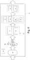
- a hybrid vehicle comprises an internal combustion thermal engine, which transmits torque to the driving wheels by means of a transmission provided with a gearbox, and at least one electric machine which is electrically connected to an electric storage system and mechanically connected to the driving wheels.
- the electric power system of a hybrid vehicle comprises a storage device provided with a chemical battery pack and a two-way electronic DC/AC power converter, which is connected to the storage device on the DC side and is connected to the electric machine on the AC side, and has the function of controlling the electric machine itself.
- the chemical batteries used in current road vehicles with hybrid propulsion may have high specific storable electric energy (i.e. per unit of mass and/or volume) and low specific deliverable electric power (i.e. per unit of mass and/or volume), and thus be adapted to meet the needs of a long trip traveled at constant speed (and, especially, with limited accelerations/decelerations).
- the chemical batteries used in current road vehicles with hybrid propulsion may have low specific storable electric energy (i.e. per unit of mass and/or volume) and high specific deliverable electric power (i.e. per unit of mass and/or volume), and thus be adapted to meet the needs of a short trip traveled at high speed (and, especially, with fast accelerations/decelerations).
- Italian patent application B02012A000315 describes an electric power system of a vehicle with electric propulsion; the electric power system has: a pair of connected electric machines; a storage system comprising two chemical battery packs electrically separated from each other; a pair of electronic DC/AC power converters, each of which exchanges electric energy with the storage system and controls a corresponding electric machine; and a pair of electronic DC/DC power converters, each of which increases the voltage and has a low-voltage side, which is electrically connected only and exclusively to a corresponding chemical battery pack, and a high-voltage side, which is connected to both electronic DC/AC power converters in parallel to the high-voltage side of the other electronic DC/DC power converter.
- the electric power system described in Italian patent application B02012A000315 has relatively high dimensions.
- Patent application EP2117106A1 which comprises the features mentioned in the preamble of claim 1, describes an electric power system of a vehicle with electric propulsion; the electric power system comprises:
- an electric power system for a vehicle with electrical propulsion is provided as claimed in the appended claims.
- reference numeral 1 indicates as a whole a road vehicle with hybrid propulsion provided with two front wheels 2 and two rear driving wheels 3, which receive torque from a hybrid propulsion system 4.
- the hybrid propulsion system 4 comprises a thermal internal combustion engine 5 arranged in front position and provided with a drive shaft 6, a transmission 7 which transmits the torque generated by the internal combustion engine 5 to the rear driving wheels 3, and two electric machines 8 and 9 which are mechanically connected to transmission 7 and are reversible (i.e. may work as electric motor by drawing electric energy and generating mechanical torque, and as electric generator by drawing mechanical energy and generating electric energy).
- one of the electric machines 8 and 9 could be mechanically connected to a turbocharger of the internal combustion engine 5 instead of being mechanically connected to transmission 7.
- Transmission 7 comprises a propeller shaft 10, which on one end is angularly integral with the drive shaft 6 and on the other end is mechanically connected to a gearbox 11, which is arranged in rear position and transmits motion to the rear driving wheels 3 by means of two axle shafts 12, which receive motion from a differential 13.
- Both electric machines 8 and 9 are mechanically connected to gearbox 11.
- the electric machine 8 is controlled by an electronic DC/AC power converter 14 (i.e. an inverter) and the electric machine 9 is driven by an electronic DC/AC power converter 15 (i.e. an inverter).
- Both electronic power converters 14 and 15 are electrically connected to an electric energy storage system 16 provided with chemical batteries.
- the storage system 16 comprises two distinct chemical battery packs 17 and 18, each of which consists of a plurality of chemical batteries connected to one another in series and/or in parallel; each chemical battery comprises respective electrochemical cells, which are adapted to convert the stored chemical energy into electric energy and vice versa.
- the chemical batteries of the two chemical battery packs 17 and 18 have different electric energy storage and delivery features: in particular, the chemical batteries of the chemical battery pack 17 have a higher specific storable electric energy (i.e. per unit of mass and/or volume) and a lower specific deliverable electric power (i.e. per unit of mass and/or volume) than the chemical batteries of the battery pack 18.
- the chemical batteries of battery pack 17 are adapted to meet the needs of a long trip traveled at moderate speed (and, especially, with limited accelerations/decelerations) because they have the advantage of being able to provide a high amount of specific electric energy (i.e. per unit of mass and/or volume) but have the disadvantage of not being able to deliver a very high specific electric power (i.e. per unit of mass and/or volume), and thus allow the road vehicle 1 to travel considerable distances in electric mode (high range), but not to allow the road vehicle 1 to achieve high dynamic performance in electric mode.
- the chemical batteries of the battery pack 18 are adapted to meet the needs of a short trip traveled at high speed (and, especially, with high accelerations/decelerations) because they have the advantage of being able to deliver a very high specific electric power (i.e. per unit of mass and/or volume) but on the contrary are not able to provide a high amount of specific electric energy (i.e. per unit of mass and/or volume), and thus allow the road vehicle 1 to achieve high dynamic performance in electric mode, but do not allow vehicle 1 to travel considerable distances in electric mode.
- the proportion between the two chemical battery packs 17 and 18 is chosen during the step of designing as a function of the desired range/performance ratio in electric mode.
- the road vehicle 1 is provided with an electric power system 20, which comprises the storage system 16 provided with two chemical battery packs 17 and 18, the two electronic power converters 14 and 15 which control the two electric machines 8 and 9, and two electronic DC/DC power converters 21 and 22 (e.g. of the "buck-boost" type) which are interposed between the chemical battery packs 17 and 18 of the storage system 16 and the two electronic power converters 14 and 15 and have the function of increasing the voltage.
- an electric power system 20 which comprises the storage system 16 provided with two chemical battery packs 17 and 18, the two electronic power converters 14 and 15 which control the two electric machines 8 and 9, and two electronic DC/DC power converters 21 and 22 (e.g. of the "buck-boost" type) which are interposed between the chemical battery packs 17 and 18 of the storage system 16 and the two electronic power converters 14 and 15 and have the function of increasing the voltage.
- the nominal voltage of the chemical battery pack 17 is 380 Volt (obviously, it could also be different, according to different alternative embodiments), the nominal voltage of the chemical battery pack 18 is 200 Volt (obviously, it could also be different according to alternative embodiments), while the nominal voltage of the electronic power converters 14 and 15 is 700 Volt (obviously, it could also be different according to alternative embodiments); therefore, the function of the electronic power converters 21 and 22 is to increase the voltage supplied by the chemical battery packs 17 and 18 to the values required by the electronic power converters 14 and 15 (it is apparent that the two electronic power converters 14 and 15 have different nominal increase ratios, because they receive differentiated electric input voltages and supply the same electric output voltage).
- the electronic power converter 21 has a low-voltage side, which is connected only to the chemical battery pack 17 (i.e. is completely isolated from the chemical battery pack 18) and a high-voltage side, which is connected in parallel to a high-voltage side of the electronic power converter 22.
- the electronic power converter 22 has a low-voltage side which is connected only to the chemical battery pack 18 (i.e. is completely isolated from the chemical battery pack 17) and a high-voltage side, which is connected in parallel to a high-voltage side of the electronic power converter 21.
- the two electronic power converters 14 and 15 are both connected in parallel to the high-voltage sides of the two electronic power converters 21 and 22 (i.e.
- the DC sides of the two electronic power converters 14 and 15 are connected to each other in parallel).
- electronic power converter 21 on low-voltage side exchanges electric energy only with the chemical battery pack 17 (i.e. not with the chemical battery pack 18) and on high-voltage side exchanges electric energy with both electronic power converters 14 and 15;
- electronic power converter 22 on low-voltage side exchanges electric energy only with the chemical battery pack 18 (i.e. not with the chemical battery pack 17) and on high-voltage side exchanges electric energy with both electronic power converters 14 and 15.
- the two electronic power converters 21 and 22 could be integrated in a single physical unit, i.e. could both be arranged inside a single container, and could thus have auxiliary components in common. Furthermore, it is worth noting that electronic power converter 21 must be optimized as a function of the features of the chemical battery pack 17 (i.e. relatively high energy and low power), while electronic power converter 22 must be optimized as a function of the chemical battery pack 18 (i.e. relatively low energy and high power).
- Each electronic power converter 21 or 22 is adapted to provide always the same constant voltage on high-voltage side (i.e. towards the electronic power converters 14 and 15) independently from the voltage present on low-voltage side (i.e. at the terminals of the corresponding the chemical battery pack 17 or 18). In other words, the transformation ratio of each electronic power converter 21 or 22 is continuously varied to maintain the voltage on high-voltage side always constant and equal to a nominal value. Furthermore, each electronic power converter 21 or 22 is adapted to filter (i.e. block, compensate) the high-frequency current/voltage oscillations generated by the electronic DC/AC power converters 14 and 15.
- the electric power system 20 comprises an electronic DC/DC power converter 23 which supplies a low-voltage section 24 (having a nominal voltage of 12 Volt) to which part of the auxiliary services of the road vehicle 1 are connected; furthermore, the electric power system 20 comprises an electronic DC/DC power converter 25 which supplies a low-voltage section 26 (having a nominal voltage of 48 Volt) to which the remaining part of the auxiliary services of the road vehicle 1 are connected.
- the auxiliary services of the road vehicle 1 which require electric power supply are divided between low-voltage sections 24 and 26; for example, the auxiliary services of the road vehicle 1 which require electric power supply may comprise an electric starter motor of the thermal engine 5, an electric motor which actuates a pump of a power steering system, an electric motor which actuates a circulation pump of a cooling system of the thermal engine 5 and/or of the electric machines 8 and 9, a radio, a lighting and indicating system etc.
- the electronic power converters 23 and 25 are normally of the one-way type (i.e. capable of transferring electric energy only towards the low-voltage sections 24 and 26 and not vice versa).
- the low-energy consumption electric/electronic devices are generally connected to the low-voltage section 24, while the electric/electronic devices with higher energy consumption (pumps, light clusters etc.) are connected to the low-voltage section 26.
- the low-voltage section 24 is generally provided with a buffer chemical battery 19 (obviously operated at 12 Volt and having a modest energy capacity compared to the chemical battery packs 17 and 18), which is arranged downstream of the electronic power converter 23, while the low-voltage section 26 is free from electric energy storage systems provided with chemical batteries (i.e. does not have any chemical battery) and receives electric energy only through the electronic power converter 25.
- the electronic power converters 23 and 25 are connected only to the chemical battery pack 17 and to the corresponding electronic power converter 21 (i.e. receive electric energy from the chemical battery pack 17 and/or from the electronic power converter 21).
- the electric power system 20 comprises a DC recharging socket 27, which is connected only to the chemical battery pack 17 by means of the interposition of an electronically controlled switch 28; the switch 28 is normally open and is closed only when the recharging socket 27 is connected to a recharging circuit.
- the chemical battery pack 17 is recharged directly by using the recharging socket 27, but the chemical battery pack 18 can also be recharged indirectly by using the electronic power converters 21 and 22 (i.e. the electric energy is converted firstly by the electronic power converter 21 and then by the electronic power converter 22 to reach the chemical battery pack 18 starting from the recharging socket 27).
- the electronic power system 20 comprises an AC recharging socket 29 which is connected to the electronic DC/AC power converter 14 (but the recharging socket 29 could be connected indifferently also to electronic DC/AC power converter 15) so as to use the electronic DC/AC power converter 14 to convert the AC coming from the recharging socket 29 into DC which through the electronic power converters 21 and 22 reaches the chemical battery packs 17 and 18 to recharge the chemical battery packs 17 and 18 themselves.
- the electronic power system 20 comprises a common container 31 which houses the accumulation system 16 (i.e. both chemical battery packs 17 and 18) and all the power electronics, i.e. the electronic power converters 14, 15, 21, 22, 23 and 25 therein.
- the storage system 16 the chemical battery packs 17 and 18
- all the power electronics the electronic power converters 14, 15, 21, 22, 23 and 25
- the buffer chemical battery 19 of the low-voltage section 24 is housed inside the common container 31.
- a lubrication system 32 of the electric machines 8 and 9 is provided to feed an adequate flow of lubrication oil to the electric machines 8 and 9 themselves.
- the lubrication system 32 is provided with a lubrication circuit comprising a tank 33 for the lubricant oil, a radiator 34 for cooling the lubricant oil, and a circulation pump 35, which is normally electrically actuated (i.e. actuated by an electric motor in DC at low voltage, preferably having a nominal voltage of 48 Volt, i.e. belonging to the low-voltage section 26).
- the two electric machines 8 and 9 are connected in parallel in the lubrication circuit of the lubrication system 32, but alternatively the two electric machines 8 and 9 could be connected in series in the lubrication circuit.
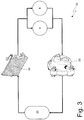
- a cooling system 36 which uses a compression refrigeration cycle for cooling all the components of the electric power system 20 (i.e. the storage system 16, the electronic power converters 14, 15, 21, 22, 23 and 25, and the electric machines 8 and 9) is provided.
- the cooling system 36 comprises a refrigeration circuit 37, which implements a compression refrigeration cycle, contains a refrigeration fluid (e.g. HCFC or hydrochlorofluorocarbons) and comprises, in turn, a compressor 38, a condenser 39, an expansion valve 40 (or lamination valve), and an evaporator 41.
- a refrigeration fluid e.g. HCFC or hydrochlorofluorocarbons
- compressor 38 is of the rotary type and is electrically actuated (i.e. is actuated in DC by an electric motor); the electric motor of compressor 38 is preferably supplied directly by the chemical battery pack 17 (as shown in figure 2 ).
- compressor 38 is operated by the shaft of the electric machine 8 or by the shaft of the electric machine 9; according to a preferred embodiment, an electrically actuated release device is interposed between the compressor 38 of the cooling system 36 and the shaft of the electric machine 8 or 9 which is controlled to connect and disconnect compressor 38 from/to the shaft of the electric machine 8 or 9 in a selective manner so as not to feed compressor 38 when the electric components do not need to be cooled.
- An air radiator (known and not shown) is thermally coupled to condenser 39 which is struck by a flow of air when vehicle 1 is moving so as to disperse the heat present in condenser 39 into the environment; according to a preferred embodiment, such a radiator is also provided with a fan controlled by a thermostat to achieve a forced cooling of the radiator itself if required.
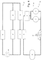
- the cooling system 36 comprises a cooling circuit 42, which contains a coolant fluid (typically water mixed with an antifreeze additive) and comprises, in turn, a heat exchanger 43 thermally coupled to evaporator 41 to release heat to the evaporator 41 itself, an electrically actuated circulation pump 44 (i.e. operated by an electric motor in DC at low voltage, preferably having a nominal voltage of 48 Volt, i.e. belonging to the low-voltage section 26), and a tank 45 of the coolant fluid.
- the cooling circuit 42 firstly extends through the common container 31 which houses the storage system 16 (i.e. both chemical battery packs 17 and 18) and all the power electronics (i.e.
- the cooling circuit 42 extends through both electric machines 8 and 9 (in the embodiment shown in figure 4 , the two electric machines 8 and 9 are connected in the cooling circuit 42 in parallel, but alternatively the two electric machines 8 and 9 may be connected in the cooling circuit 42 in series).
- corresponding cooling labyrinths in which the coolant fluid flows are obtained in the electric machines 8 and 9 (generally in the stator pack).
- the coolant fluid in the common container 31 firstly flows through the chemical battery packs 17 and 18, then flows through the electronic power converters 21, 22, 23 and 25, and finally flows through the electronic power converters 14 and 15.
- the chemical battery packs 17 and 18, the electronic power converters 21, 22, 23 and 25, and the electronic power converters 14 and 15 are arranged in series (in this order) along the cooling circuit 42.
- bypass circuits are provided in the common container 31 with electronically controlled solenoid valves to adjust the cooling of the single parts (i.e. to adjust the amount of cooling of the chemical battery packs 17 and 18, the amount of cooling of the electronic power converters 21, 22, 23 and 25, and the amount of cooling of the electronic power converters 14 and 15).
- the tank 45 of the coolant fluid and the electrically operated circulation pump 44 are housed in the common container 31.
- the cooling circuit 42 does not concern the buffer chemical battery 19 of the low-voltage section 24 (even though such a chemical battery 19 is housed in the common container 31 in all cases).
- the efficiency of the electric machines 8 and 9 and the electronic power converters 14, 15, 21, 22, 23 and 25 is higher if their temperature is lower (obviously within given limits, particularly for the electronic components) because the lower the temperature of the conductors, the lower the electric resistance of the conductors themselves.
- the chemical battery packs 17 and 18 of the storage system 16 optimally work within a given temperature range: if the chemical battery packs 17 and 18 are too cold, their discharge capacity decreases (i.e. less energy is delivered), while if the chemical battery packs 17 and 18 are too hot, the self-discharge (i.e.
- the temperature of the chemical battery packs 17 and 18 must be controlled, thus avoiding the chemical battery packs 17 and 18 from being cooled when the chemical battery packs 17 and 18 are too cold (which event is however rare and bound to particularly cold external temperatures) and cooling the chemical battery packs 17 and 18 when the chemical battery packs 17 and 18 are too hot.
- a control unit determines the temperature of each electric/electronic component by means of indirect estimates, e.g. based on electric resistance measurements or by means of a specific temperature sensor. According to the temperatures of the electric/electronic components, the control unit decides whether to generate cold in the refrigeration circuit 37 and thus whether to actuate compressor 38. Furthermore, according to the temperatures of each electric/electronic component, the control unit decides the amount of cooling of the electric/electronic component.
- the refrigeration circuit 37 is also used by the climate control system of the passenger compartment of vehicle 1; in other words, the refrigeration circuit 37 is shared by the cooling system 36 of the electric power system 20 and the climate control system of the passenger compartment of vehicle 1. Therefore, the refrigeration circuit 37 comprises a further expansion valve 46 (or lamination valve) connected in parallel to the expansion valve 40 and a further evaporator 47 thermally coupled to the climate control system of the passenger compartment of vehicle 1.
- a greater number of chemical battery packs are provided, each of which is electrically connected to its own DC/DC electronic power converter which has a low-voltage side connected only to its own chemical battery pack and a high-voltage side which is connected in parallel to the high-pressure sides of the other electronic DC/DC power converters.
- a lower number (one) or a higher number (e.g. three or four) of electric machines each of which is controlled by a corresponding electronic power converter which is connected at the input and in parallel to the electronic power converters 14 and 15.
- Such electric machines may be mechanically connected to transmission 7, may be mechanically connected to the drive shaft 6 of the internal combustion engine 5, may be mechanically connected to a turbocharger of the internal combustion engine 5, or may be also connected to auxiliary services of vehicle 1 (cooling, lubrication etc.).
- the above-described electric power system 20 has many advantages.
- the two chemical battery packs 17 and 18 are managed in a completely independent manner because the low-voltage sides of the two electronic power converters 21 and 22 are entirely isolated (separate). Therefore, the voltages at the terminals of the two chemical battery packs 17 and 18 may be different in terms of nominal value and variation in use, because it is the task of the electronic power converters 21 and 22 to "equalize" the voltage on high-voltage side (i.e. towards the electronic power converters 14 and 15).
- This aspect is very important because, as mentioned above, the chemical battery packs 17 and 18 have very different features and thus require different managements in order to operate in an optimal manner.
- the chemical battery packs 17 and 18 do not exchange electric energy directly with the electronic power converters 14 and 15 which control the electric machines 8 and 9, but on the contrary the chemical battery packs 17 and 18 exchange electric energy with the electronic power converters 21 and 22, which, by filtering the high-frequency current/voltage oscillations generated by the electronic power converters 14 and 15, allow the chemical battery packs 17 and 18 to be operated in the best manner possible.
- the electronic power converters 21 and 22 filter the high-frequency current/voltage oscillations generated by the electronic power converters 14 and 15 and thus prevent such high-frequency current voltage oscillations from discharging on the chemical battery packs 17 and 18 which cause an early wear of the chemical battery packs 17 and 18 themselves.
- Another positive function of the electronic power converters 21 and 22 is to maintain constant the voltage on high-voltage side, i.e. towards the electronic power converters 14 and 15 which control the electric machines 8 and 9 independently from the actual voltage at the terminals of the chemical battery packs 17 and 18.
- the actual voltages at the terminals of the chemical battery packs 17 and 18 may be mutually different and especially change greatly as a function of the charge state (also of 20-30% from full charge to discharged); the electronic power converters 21 and 22 can self-adjust to have always the same voltage value on the high-voltage side, i.e. towards the electronic power converters 14 and 15 (also in the case of failure of a chemical battery pack 17 or 18 with consequent disconnection of the faulty chemical battery pack 17 or 18).
- the electronic power converters 14 and 15 cannot modify the voltage value and therefore would not be able to compensate for the voltage differences determined by the chemical battery packs 17 and 18.
- the two electric machines 8 and 9 may exchange their electric energy (through the electronic power converters 14 and 15) without passing through the chemical battery packs 17 or 18 of the storage system 16; thereby, the exchange of electric energy between the two electric machines 8 and 9 do not cause any type of wear in the storage system 16 or any energy dissipation in the storage system 16.
- the nominal voltage of the electrical machines 8 and 9 may be much higher than the nominal voltage of the chemical battery packs 17 and 18 of the storage system 16; thereby, the nominal voltage of the electric machines 8 and 9 can be optimized independently from the nominal voltage of the chemical battery packs 17 and 18 (the nominal voltage of the chemical battery packs 17 and 18 cannot be too high because of the technological and constructional limits of the electrochemical cells). It is worth noting that, by increasing the nominal voltage of the electric machines 8 and 9, the section of the electric conductors of the electric machines 8 and 9 may be reduced, as well as, ultimately, the overall dimension and weight of the electric machines 8 and 9 and of the wires which connect the electronic power converters 14 and 15 to the electric machines 8 and 9.
Description
- The present invention relates to an electric power system of a vehicle with electric propulsion.
- The present invention is advantageously applied to a road vehicle with hybrid propulsion, to which explicit reference will be made in the following description without therefore losing in generality.
- A hybrid vehicle comprises an internal combustion thermal engine, which transmits torque to the driving wheels by means of a transmission provided with a gearbox, and at least one electric machine which is electrically connected to an electric storage system and mechanically connected to the driving wheels.
- The electric power system of a hybrid vehicle comprises a storage device provided with a chemical battery pack and a two-way electronic DC/AC power converter, which is connected to the storage device on the DC side and is connected to the electric machine on the AC side, and has the function of controlling the electric machine itself.
- The chemical batteries used in current road vehicles with hybrid propulsion may have high specific storable electric energy (i.e. per unit of mass and/or volume) and low specific deliverable electric power (i.e. per unit of mass and/or volume), and thus be adapted to meet the needs of a long trip traveled at constant speed (and, especially, with limited accelerations/decelerations). Alternatively, the chemical batteries used in current road vehicles with hybrid propulsion may have low specific storable electric energy (i.e. per unit of mass and/or volume) and high specific deliverable electric power (i.e. per unit of mass and/or volume), and thus be adapted to meet the needs of a short trip traveled at high speed (and, especially, with fast accelerations/decelerations).
- In order to attempt to obtain an acceptable trade-off between range needs (for which chemical batteries which have high specific electric energy are required) and performance needs (for which chemical batteries which have high specific electric power are required), it has been attempted to manufacture trade-off chemical batteries which have intermediate features between the two extremes; however, it has been observed that such trade-off chemical batteries are a "second-rate" trade-off, i.e. the significant reduction of specific electric energy does not correspond to an equally significant increase of specific electric power, and vice versa.
- In order to attempt to obtain an acceptable trade-off between range needs (for which chemical batteries which have high specific electric energy are required) and performance needs (for which chemical batteries which have high specific power are required), it has also been suggested to include both chemical batteries which have high specific electric energy and chemical batteries which have high specific energy in the storage system. However, the overall results (in terms of range and performance) and in particular the operative lifespan of the chemical batteries have been found not to be entirely satisfactory because the "final result" was in some way inferior to the sum of the single parts.
- Italian patent application
B02012A000315 B02012A000315 - Patent application
EP2117106A1 , which comprises the features mentioned in the preamble ofclaim 1, describes an electric power system of a vehicle with electric propulsion; the electric power system comprises: - two electric machines MG1 and MG2;
- a storage system comprising two
chemical battery packs - a first electronic DC/AC power converter INV1, which exchanges electric energy with the storage system and controls a first electric machine MG1;
- a second electronic DC/AC power converter INV2, which exchanges electric energy with the storage system and controls a second electric machine MG2;
- a first electronic DC/
DC power converter 18, which increases the voltage and has a low-voltage side, which is electrically connected only and exclusively to a firstchemical battery pack 10, and a high-voltage side, which is connected to both electronic DC/AC power converters INV1, INV2; and - a second electronic DC/
DC power converter 28, which increases the voltage and has a low-voltage side, which is electrically connected only and exclusively to a secondchemical battery pack 20, and a high-voltage side, which is connected to both electronic DC/AC power converters INV1, INV2 in parallel to the high-voltage side of the first electronic DC/DC power converter CONV1. - It is the object of the present invention to provide an electric power system for a vehicle with electric propulsion, which is free from the above-described drawbacks while being easy and cost-effective to be manufactured.
- According to the present invention, an electric power system for a vehicle with electrical propulsion is provided as claimed in the appended claims.
- The present invention will now be described with reference to the accompanying drawings, which show a non-limitative embodiment thereof, in which:
-
figure 1 is a diagrammatic, plan view of a road vehicle with hybrid propulsion; -
figure 2 is a diagrammatic view of an electric power system of the vehicle infigure 1 ; -
figure 3 is a diagrammatic view of a lubrication system of the electric machines of the road vehicle infigure 1 ; -
figure 4 is a diagrammatic view of a cooling system of the electric power system infigure 2 ; -
figure 5 is a diagrammatic view on enlarged scale of a detail infigure 4 ; and -
figure 6 is a diagrammatic view on enlarged scale of an alternative embodiment of the detail infigure 5 . - In
figure 1 ,reference numeral 1 indicates as a whole a road vehicle with hybrid propulsion provided with twofront wheels 2 and tworear driving wheels 3, which receive torque from a hybrid propulsion system 4. - The hybrid propulsion system 4 comprises a thermal
internal combustion engine 5 arranged in front position and provided with adrive shaft 6, atransmission 7 which transmits the torque generated by theinternal combustion engine 5 to therear driving wheels 3, and twoelectric machines transmission 7 and are reversible (i.e. may work as electric motor by drawing electric energy and generating mechanical torque, and as electric generator by drawing mechanical energy and generating electric energy). Alternatively, one of theelectric machines 8 and 9 (or a further third electric machine) could be mechanically connected to a turbocharger of theinternal combustion engine 5 instead of being mechanically connected totransmission 7. -
Transmission 7 comprises apropeller shaft 10, which on one end is angularly integral with thedrive shaft 6 and on the other end is mechanically connected to agearbox 11, which is arranged in rear position and transmits motion to therear driving wheels 3 by means of twoaxle shafts 12, which receive motion from adifferential 13. - Both
electric machines gearbox 11. Theelectric machine 8 is controlled by an electronic DC/AC power converter 14 (i.e. an inverter) and theelectric machine 9 is driven by an electronic DC/AC power converter 15 (i.e. an inverter). Bothelectronic power converters energy storage system 16 provided with chemical batteries. - As shown in
figure 2 , thestorage system 16 comprises two distinctchemical battery packs chemical battery packs chemical battery pack 17 have a higher specific storable electric energy (i.e. per unit of mass and/or volume) and a lower specific deliverable electric power (i.e. per unit of mass and/or volume) than the chemical batteries of thebattery pack 18. - Therefore, the chemical batteries of
battery pack 17 are adapted to meet the needs of a long trip traveled at moderate speed (and, especially, with limited accelerations/decelerations) because they have the advantage of being able to provide a high amount of specific electric energy (i.e. per unit of mass and/or volume) but have the disadvantage of not being able to deliver a very high specific electric power (i.e. per unit of mass and/or volume), and thus allow theroad vehicle 1 to travel considerable distances in electric mode (high range), but not to allow theroad vehicle 1 to achieve high dynamic performance in electric mode. Instead, the chemical batteries of thebattery pack 18 are adapted to meet the needs of a short trip traveled at high speed (and, especially, with high accelerations/decelerations) because they have the advantage of being able to deliver a very high specific electric power (i.e. per unit of mass and/or volume) but on the contrary are not able to provide a high amount of specific electric energy (i.e. per unit of mass and/or volume), and thus allow theroad vehicle 1 to achieve high dynamic performance in electric mode, but do not allowvehicle 1 to travel considerable distances in electric mode. The proportion between the twochemical battery packs - As shown in
figure 2 , theroad vehicle 1 is provided with anelectric power system 20, which comprises thestorage system 16 provided with twochemical battery packs electronic power converters electric machines DC power converters 21 and 22 (e.g. of the "buck-boost" type) which are interposed between thechemical battery packs storage system 16 and the twoelectronic power converters chemical battery pack 17 is 380 Volt (obviously, it could also be different, according to different alternative embodiments), the nominal voltage of thechemical battery pack 18 is 200 Volt (obviously, it could also be different according to alternative embodiments), while the nominal voltage of theelectronic power converters electronic power converters chemical battery packs electronic power converters 14 and 15 (it is apparent that the twoelectronic power converters - The
electronic power converter 21 has a low-voltage side, which is connected only to the chemical battery pack 17 (i.e. is completely isolated from the chemical battery pack 18) and a high-voltage side, which is connected in parallel to a high-voltage side of theelectronic power converter 22. Similarly, theelectronic power converter 22 has a low-voltage side which is connected only to the chemical battery pack 18 (i.e. is completely isolated from the chemical battery pack 17) and a high-voltage side, which is connected in parallel to a high-voltage side of theelectronic power converter 21. The twoelectronic power converters electronic power converters 21 and 22 (i.e. the DC sides of the twoelectronic power converters electronic power converter 21 on low-voltage side exchanges electric energy only with the chemical battery pack 17 (i.e. not with the chemical battery pack 18) and on high-voltage side exchanges electric energy with bothelectronic power converters electronic power converter 22 on low-voltage side exchanges electric energy only with the chemical battery pack 18 (i.e. not with the chemical battery pack 17) and on high-voltage side exchanges electric energy with bothelectronic power converters - It is worth noting that the two
electronic power converters electronic power converter 21 must be optimized as a function of the features of the chemical battery pack 17 (i.e. relatively high energy and low power), whileelectronic power converter 22 must be optimized as a function of the chemical battery pack 18 (i.e. relatively low energy and high power). - Each
electronic power converter electronic power converters 14 and 15) independently from the voltage present on low-voltage side (i.e. at the terminals of the corresponding thechemical battery pack 17 or 18). In other words, the transformation ratio of eachelectronic power converter electronic power converter AC power converters - The
electric power system 20 comprises an electronic DC/DC power converter 23 which supplies a low-voltage section 24 (having a nominal voltage of 12 Volt) to which part of the auxiliary services of theroad vehicle 1 are connected; furthermore, theelectric power system 20 comprises an electronic DC/DC power converter 25 which supplies a low-voltage section 26 (having a nominal voltage of 48 Volt) to which the remaining part of the auxiliary services of theroad vehicle 1 are connected. In other words, the auxiliary services of theroad vehicle 1 which require electric power supply are divided between low-voltage sections road vehicle 1 which require electric power supply may comprise an electric starter motor of thethermal engine 5, an electric motor which actuates a pump of a power steering system, an electric motor which actuates a circulation pump of a cooling system of thethermal engine 5 and/or of theelectric machines electronic power converters voltage sections voltage section 24, while the electric/electronic devices with higher energy consumption (pumps, light clusters etc.) are connected to the low-voltage section 26. The low-voltage section 24 is generally provided with a buffer chemical battery 19 (obviously operated at 12 Volt and having a modest energy capacity compared to thechemical battery packs 17 and 18), which is arranged downstream of theelectronic power converter 23, while the low-voltage section 26 is free from electric energy storage systems provided with chemical batteries (i.e. does not have any chemical battery) and receives electric energy only through theelectronic power converter 25. - In the embodiment shown in
figure 2 , theelectronic power converters chemical battery pack 17 and to the corresponding electronic power converter 21 (i.e. receive electric energy from thechemical battery pack 17 and/or from the electronic power converter 21). - The
electric power system 20 comprises aDC recharging socket 27, which is connected only to thechemical battery pack 17 by means of the interposition of an electronically controlledswitch 28; theswitch 28 is normally open and is closed only when therecharging socket 27 is connected to a recharging circuit. Obviously, thechemical battery pack 17 is recharged directly by using the rechargingsocket 27, but thechemical battery pack 18 can also be recharged indirectly by using theelectronic power converters 21 and 22 (i.e. the electric energy is converted firstly by theelectronic power converter 21 and then by theelectronic power converter 22 to reach thechemical battery pack 18 starting from the recharging socket 27). - The
electronic power system 20 comprises anAC recharging socket 29 which is connected to the electronic DC/AC power converter 14 (but the rechargingsocket 29 could be connected indifferently also to electronic DC/AC power converter 15) so as to use the electronic DC/AC power converter 14 to convert the AC coming from the rechargingsocket 29 into DC which through theelectronic power converters chemical battery packs chemical battery packs - The
electronic power system 20 comprises acommon container 31 which houses the accumulation system 16 (i.e. bothchemical battery packs 17 and 18) and all the power electronics, i.e. theelectronic power converters electronic power converters common container 31. According to a preferred (but not binding) embodiment, thebuffer chemical battery 19 of the low-voltage section 24 is housed inside thecommon container 31. - As shown in
figure 3 , alubrication system 32 of theelectric machines electric machines lubrication system 32 is provided with a lubrication circuit comprising atank 33 for the lubricant oil, aradiator 34 for cooling the lubricant oil, and acirculation pump 35, which is normally electrically actuated (i.e. actuated by an electric motor in DC at low voltage, preferably having a nominal voltage of 48 Volt, i.e. belonging to the low-voltage section 26). In the embodiment shown infigure 3 , the twoelectric machines lubrication system 32, but alternatively the twoelectric machines - As shown in
figure 4 , acooling system 36, which uses a compression refrigeration cycle for cooling all the components of the electric power system 20 (i.e. thestorage system 16, theelectronic power converters electric machines 8 and 9) is provided. Thecooling system 36 comprises arefrigeration circuit 37, which implements a compression refrigeration cycle, contains a refrigeration fluid (e.g. HCFC or hydrochlorofluorocarbons) and comprises, in turn, acompressor 38, acondenser 39, an expansion valve 40 (or lamination valve), and anevaporator 41. - According to a preferred embodiment,
compressor 38 is of the rotary type and is electrically actuated (i.e. is actuated in DC by an electric motor); the electric motor ofcompressor 38 is preferably supplied directly by the chemical battery pack 17 (as shown infigure 2 ). Alternatively,compressor 38 is operated by the shaft of theelectric machine 8 or by the shaft of theelectric machine 9; according to a preferred embodiment, an electrically actuated release device is interposed between thecompressor 38 of thecooling system 36 and the shaft of theelectric machine compressor 38 from/to the shaft of theelectric machine compressor 38 when the electric components do not need to be cooled. - An air radiator (known and not shown) is thermally coupled to
condenser 39 which is struck by a flow of air whenvehicle 1 is moving so as to disperse the heat present incondenser 39 into the environment; according to a preferred embodiment, such a radiator is also provided with a fan controlled by a thermostat to achieve a forced cooling of the radiator itself if required. - Furthermore, the
cooling system 36 comprises acooling circuit 42, which contains a coolant fluid (typically water mixed with an antifreeze additive) and comprises, in turn, aheat exchanger 43 thermally coupled toevaporator 41 to release heat to theevaporator 41 itself, an electrically actuated circulation pump 44 (i.e. operated by an electric motor in DC at low voltage, preferably having a nominal voltage of 48 Volt, i.e. belonging to the low-voltage section 26), and atank 45 of the coolant fluid. Thecooling circuit 42 firstly extends through thecommon container 31 which houses the storage system 16 (i.e. both chemical battery packs 17 and 18) and all the power electronics (i.e. theelectronic power converters cooling circuit 42 extends through bothelectric machines 8 and 9 (in the embodiment shown infigure 4 , the twoelectric machines cooling circuit 42 in parallel, but alternatively the twoelectric machines cooling circuit 42 in series). There may be heat exchangers in thecommon container 31, each of which is thermally coupled to the corresponding electric/electronic component to adsorb heat from the electric/electronic component itself. Instead, corresponding cooling labyrinths in which the coolant fluid flows are obtained in theelectric machines 8 and 9 (generally in the stator pack). As shown infigure 5 , the coolant fluid in thecommon container 31 firstly flows through the chemical battery packs 17 and 18, then flows through theelectronic power converters electronic power converters common container 31, the chemical battery packs 17 and 18, theelectronic power converters electronic power converters circuit 42. According to a preferred (but not binding) embodiment, bypass circuits are provided in thecommon container 31 with electronically controlled solenoid valves to adjust the cooling of the single parts (i.e. to adjust the amount of cooling of the chemical battery packs 17 and 18, the amount of cooling of theelectronic power converters electronic power converters 14 and 15). According to the variant shown infigure 6 , thetank 45 of the coolant fluid and the electrically operatedcirculation pump 44 are housed in thecommon container 31. - According to a preferred embodiment, the cooling
circuit 42 does not concern thebuffer chemical battery 19 of the low-voltage section 24 (even though such achemical battery 19 is housed in thecommon container 31 in all cases). - The efficiency of the
electric machines electronic power converters storage system 16 optimally work within a given temperature range: if the chemical battery packs 17 and 18 are too cold, their discharge capacity decreases (i.e. less energy is delivered), while if the chemical battery packs 17 and 18 are too hot, the self-discharge (i.e. the energy which is lost during processes inside the chemical batteries) increases; therefore, in order to maximize the efficiency and efficacy of the chemical battery packs 17 and 18, the temperature of the chemical battery packs 17 and 18 must be controlled, thus avoiding the chemical battery packs 17 and 18 from being cooled when the chemical battery packs 17 and 18 are too cold (which event is however rare and bound to particularly cold external temperatures) and cooling the chemical battery packs 17 and 18 when the chemical battery packs 17 and 18 are too hot. - In use, a control unit determines the temperature of each electric/electronic component by means of indirect estimates, e.g. based on electric resistance measurements or by means of a specific temperature sensor. According to the temperatures of the electric/electronic components, the control unit decides whether to generate cold in the
refrigeration circuit 37 and thus whether to actuatecompressor 38. Furthermore, according to the temperatures of each electric/electronic component, the control unit decides the amount of cooling of the electric/electronic component. - According to a preferred (but not binding) embodiment shown in
figure 4 , therefrigeration circuit 37 is also used by the climate control system of the passenger compartment ofvehicle 1; in other words, therefrigeration circuit 37 is shared by thecooling system 36 of theelectric power system 20 and the climate control system of the passenger compartment ofvehicle 1. Therefore, therefrigeration circuit 37 comprises a further expansion valve 46 (or lamination valve) connected in parallel to theexpansion valve 40 and afurther evaporator 47 thermally coupled to the climate control system of the passenger compartment ofvehicle 1. - According to a different embodiment (not shown, but perfectly equivalent), a greater number of chemical battery packs are provided, each of which is electrically connected to its own DC/DC electronic power converter which has a low-voltage side connected only to its own chemical battery pack and a high-voltage side which is connected in parallel to the high-pressure sides of the other electronic DC/DC power converters.
- According to a different embodiment (not shown but perfectly equivalent), a lower number (one) or a higher number (e.g. three or four) of electric machines, each of which is controlled by a corresponding electronic power converter which is connected at the input and in parallel to the
electronic power converters transmission 7, may be mechanically connected to thedrive shaft 6 of theinternal combustion engine 5, may be mechanically connected to a turbocharger of theinternal combustion engine 5, or may be also connected to auxiliary services of vehicle 1 (cooling, lubrication etc.). - The above-described
electric power system 20 has many advantages. - Firstly, the two chemical battery packs 17 and 18 are managed in a completely independent manner because the low-voltage sides of the two
electronic power converters electronic power converters electronic power converters 14 and 15). This aspect is very important because, as mentioned above, the chemical battery packs 17 and 18 have very different features and thus require different managements in order to operate in an optimal manner. - Furthermore, the chemical battery packs 17 and 18 do not exchange electric energy directly with the
electronic power converters electric machines electronic power converters electronic power converters electronic power converters electronic power converters - Another positive function of the
electronic power converters electronic power converters electric machines electronic power converters electronic power converters 14 and 15 (also in the case of failure of achemical battery pack chemical battery pack 17 or 18). With this regard, it is worth noting that theelectronic power converters - The two
electric machines electronic power converters 14 and 15) without passing through the chemical battery packs 17 or 18 of thestorage system 16; thereby, the exchange of electric energy between the twoelectric machines storage system 16 or any energy dissipation in thestorage system 16. - By virtue of the presence of the
electronic power converters electrical machines storage system 16; thereby, the nominal voltage of theelectric machines electric machines electric machines electric machines electronic power converters electric machines - Finally, since the chemical battery packs 17 and 18 and the
electronic power converters common container 31, the overall dimensions of the electric system may be reduced, the length and dimension of the electric wiring may be minimized, and the operation of cooling may be considerably simplified, thus making it more efficient and effective.
Claims (13)
- An electric power system (20) of a vehicle (1) with electric propulsion; the electric power system (20) comprises:at least a first electric machine (8);a storage system (16) comprising at least two chemical battery packs (17, 18) electrically separated from each other;a first electronic DC/AC power converter (14), which exchanges electric energy with the storage system (16) and controls the first electric machine (8);a first electronic DC/DC power converter (21), which increases the voltage and has a low-voltage side, which is electrically connected only and exclusively to a first chemical battery pack (17), and a high-voltage side, which is connected to the first electronic DC/AC power converter (14); anda second electronic DC/DC power converter (22), which increases the voltage and has a low-voltage side, which is electrically connected only and exclusively to a second chemical battery pack (18), and a high-voltage side, which is connected to the first electronic DC/AC power converter (14) in parallel to the high-voltage side of the first electronic DC/DC power converter (21);the electric power system (20) is characterized in that it comprises:a common container (31), which houses the storage system (16) therein, comprising the two chemical battery packs (17, 18), the first electronic DC/AC power converter (14), the first electronic DC/DC power converter (21), and the second electronic DC/DC power converter (22); anda cooling system (36), which uses a compression refrigeration cycle to cool the storage system (16), the electronic power converters (14, 15, 21, 22, 23, 25), and the first electric machine (8);wherein the cooling system (36) comprises:a refrigeration circuit (37), which implements a compression refrigeration cycle, contains a refrigerant fluid, and comprises, in turn, a compressor (38), a condenser (39), a first expansion valve (40), and a first evaporator (41); anda cooling circuit (42), which extends through the common container (31) and then through the first electric machine (8), contains a coolant fluid and comprises, in turn, a heat exchanger (43), which is thermally coupled to the evaporator (41) so as to release heat to the evaporator (41) itself, an electrically operated circulation pump (44), and a tank (45) for the coolant fluid; andwherein, inside the common container (31), the coolant fluid firstly flows through the battery packs (17, 18), then flows through the electronic DC/DC power converters (21, 22), and finally flows through the first electronic DC/AC power converter (14).
- An electric power system (20) according to claim 1, wherein the compressor (38) is electrically operated by means of an electric motor, which is directly supplied with power by the first chemical battery pack (17).
- An electric power system (20) according to claim 1 or 2, wherein the common container (31) also houses the circulation pump (44) of the cooling circuit (42).
- An electric power system (20) according to claim 3, wherein the common container (31) also houses the tank (45) for the coolant fluid of the cooling circuit (42).
- An electric power system (20) according to one of the claims from 1 to 4, wherein the refrigeration circuit (37) is also used by a climate control system of a passenger compartment of the vehicle (1) and comprises a second expansion valve (46) connected in parallel to the first expansion valve (40) and a second evaporator (47) thermally coupled to the climate control system of the passenger compartment of the vehicle (1).
- An electric power system (20) according to any one of the claims from 1 to 5 and comprising:a second electric machine (9); anda second electronic DC/AC power converter (15), which exchanges electric energy with the storage system (16), controls the second electric machine (9), is connected to the parallel between the high-voltage sides of the electronic DC/DC power converters (21, 22), and is housed inside the common container (31).
- An electric power system (20) according to any one of the claims from 1 to 6 and comprising:a third electronic DC/DC power converter (23), which reduces the voltage, is adapted to supply power to a first low-voltage section (24), to which auxiliary services of the road vehicle (1) are connected, is electrically connected to the first chemical battery pack (17), and is housed inside the common container (31); anda fourth electronic DC/DC power converter (25), which reduces the voltage, is adapted to supply power to a second low-voltage section (26), to which auxiliary services of the road vehicle (1) are connected, is electrically connected to the first chemical battery pack (17), and is housed inside the common container (31).
- An electric power system (20) according to claim 7, wherein:the first low-voltage section (24) has a nominal voltage which is lower than the nominal voltage of the second low-voltage section (26);the first low-voltage section (24) comprises a buffer chemical battery (19), which is arranged downstream of the third electronic DC/DC power converter (23); andthe second low-voltage section (26) has no electric energy storage systems provided with chemical batteries.
- An electric power system (20) according to any one of the claims from 1 to 8, wherein the first chemical battery pack (17) has a greater specific storable electric energy and a smaller specific deliverable electric power compared to the second chemical battery pack (18).
- An electric power system (20) according to any one of the claims from 1 to 9 and comprising a DC recharging socket (27), which is connected only to the first chemical battery pack (17) by means of the interposition of an electronically controlled switch (28).
- An electric power system (20) according to any one of the claims from 1 to 10 and comprising an AC recharging socket (29), which is connected to the first electronic DC/AC power converter (14).
- An electric power system (20) according to claim 10, wherein the switch (28) is normally open and is closed only when the DC recharging socket (27) is connected to a recharging circuit.
- An electric power system (20) according to claim 10 or 12, wherein by using the DC recharging socket (27) the first chemical battery pack (17) is recharged directly and the second chemical battery pack (18) may be charged indirectly by using both DC-DC electronic power converters (21, 22).
Applications Claiming Priority (1)
| Application Number | Priority Date | Filing Date | Title |
|---|---|---|---|
| ITBO20140336 | 2014-06-17 |
Publications (3)
| Publication Number | Publication Date |
|---|---|
| EP2965935A2 EP2965935A2 (en) | 2016-01-13 |
| EP2965935A3 EP2965935A3 (en) | 2016-04-06 |
| EP2965935B1 true EP2965935B1 (en) | 2017-10-04 |
Family
ID=51541134
Family Applications (1)
| Application Number | Title | Priority Date | Filing Date |
|---|---|---|---|
| EP15172237.8A Active EP2965935B1 (en) | 2014-06-17 | 2015-06-16 | Electric power system of a vehicle with electric propulsion |
Country Status (2)
| Country | Link |
|---|---|
| US (1) | US9895981B2 (en) |
| EP (1) | EP2965935B1 (en) |
Families Citing this family (14)
| Publication number | Priority date | Publication date | Assignee | Title |
|---|---|---|---|---|
| US10290911B2 (en) * | 2015-05-18 | 2019-05-14 | Toyota Motor Engineering & Manufacturing North America, Inc. | Cooling loops and vehicles incorporating the same |
| JP6558313B2 (en) * | 2016-06-29 | 2019-08-14 | トヨタ自動車株式会社 | Vehicle and manufacturing method thereof |
| GB2553808A (en) * | 2016-09-15 | 2018-03-21 | Arrival Ltd | Cooling electric motors in a vehicle drivetrain apparatus |
| DE102018200780B4 (en) * | 2017-05-16 | 2023-12-21 | Ford Global Technologies, Llc | Plug-in hybrid vehicle with an internal combustion engine that can be charged using an exhaust gas turbocharger |
| DE102018000491A1 (en) * | 2018-01-22 | 2018-07-12 | Daimler Ag | Storage device for a motor vehicle, in particular for an electric vehicle |
| DE102018103713A1 (en) | 2018-02-20 | 2019-08-22 | Dr. Ing. H.C. F. Porsche Aktiengesellschaft | Mechanical and thermal system for a modular battery with power electronics components |
| DE102018104914A1 (en) * | 2018-03-05 | 2019-09-05 | Dr. Ing. H.C. F. Porsche Aktiengesellschaft | Integrated power box |
| IT201800006205A1 (en) * | 2018-06-11 | 2019-12-11 | ELECTRICAL POWER SYSTEM OF A VEHICLE WITH ELECTRIC PROPULSION | |
| IT201800006790A1 (en) * | 2018-06-28 | 2019-12-28 | AUXILIARY POWER SUPPLY SYSTEM FOR HIGH POWER LOADS IN A HYBRID / ELECTRIC VEHICLE | |
| IT201800009787A1 (en) * | 2018-10-25 | 2020-04-25 | Italdesign-Giugiaro SPA | System for cooling removable battery modules in an electric or hybrid drive vehicle. |
| IT201900005664A1 (en) * | 2019-04-12 | 2020-10-12 | Ferrari Spa | ELECTRICAL SYSTEM OF A ROAD VEHICLE FITTED WITH A DC-DC ELECTRONIC POWER CONVERTER |
| DE102020215889A1 (en) * | 2020-12-15 | 2022-06-15 | Robert Bosch Gesellschaft mit beschränkter Haftung | Energy management system for a motor vehicle, motor vehicle, method |
| FR3123597B1 (en) * | 2021-06-08 | 2023-04-21 | Psa Automobiles Sa | COMPACT SUB-ASSEMBLY FOR MOTOR VEHICLE ELECTROMOTOR GROUP |
| EP4335709A1 (en) * | 2022-09-12 | 2024-03-13 | FERRARI S.p.A. | Road vehicle provided with an electronic dc-dc power converter and corresponding control method |
Family Cites Families (16)
| Publication number | Priority date | Publication date | Assignee | Title |
|---|---|---|---|---|
| JPH11180163A (en) * | 1997-12-18 | 1999-07-06 | Honda Motor Co Ltd | Electric vehicle |
| US6608396B2 (en) | 2001-12-06 | 2003-08-19 | General Motors Corporation | Electrical motor power management system |
| JP4179351B2 (en) * | 2006-07-07 | 2008-11-12 | トヨタ自動車株式会社 | Power supply system, vehicle equipped with the same, method for controlling power supply system, and computer-readable recording medium recording a program for causing computer to execute control of power supply system |
| JP4466620B2 (en) * | 2006-07-10 | 2010-05-26 | トヨタ自動車株式会社 | Power supply system and vehicle equipped with the same |
| BRPI0718370B1 (en) * | 2006-09-29 | 2018-11-06 | Toyota Motor Co Ltd | power source device charged by an external power source and vehicle |
| JP4569603B2 (en) * | 2007-01-04 | 2010-10-27 | トヨタ自動車株式会社 | Power supply system, vehicle including the same, and control method thereof |
| JP4144646B1 (en) * | 2007-02-20 | 2008-09-03 | トヨタ自動車株式会社 | Electric vehicle, vehicle charging device, and vehicle charging system |
| JP4479768B2 (en) * | 2007-09-10 | 2010-06-09 | トヨタ自動車株式会社 | Automobile and auto charging method |
| JP4332861B2 (en) * | 2008-01-16 | 2009-09-16 | トヨタ自動車株式会社 | Vehicle charging control device |
| MX2010014560A (en) * | 2008-06-27 | 2011-06-16 | Proterra Inc | Vehicle battery systems and methods. |
| JP4655124B2 (en) * | 2008-08-25 | 2011-03-23 | トヨタ自動車株式会社 | Control device for hybrid vehicle |
| JP5024454B2 (en) * | 2008-10-31 | 2012-09-12 | トヨタ自動車株式会社 | Electric vehicle power supply system and control method thereof |
| US8598852B2 (en) * | 2008-11-12 | 2013-12-03 | American Axle & Manufacturing, Inc. | Cost effective configuration for supercapacitors for HEV |
| FR2969050B1 (en) * | 2010-12-21 | 2014-10-17 | Renault Sa | METHOD AND SYSTEM FOR REGULATING THE TEMPERATURE OF A POWER BATTERY OF A POWER-DRIVEN VEHICLE AND VEHICLE EQUIPPED WITH SUCH A SYSTEM |
| DE102011051624A1 (en) * | 2011-07-07 | 2013-01-10 | Dr. Ing. H.C. F. Porsche Aktiengesellschaft | Cooling system for use in motor vehicle, has heating circuit comprised of electrical heater, pump, and valves, so that one branch pipe is bypassed by another branch pipe for heat exchange with internal combustion engine |
| CN104272554A (en) * | 2011-12-02 | 2015-01-07 | 纳迪姆·卡里姆 | Dual chemistry, battery system for use in plug-in or hybrid electric vehicles |
-
2015
- 2015-06-16 EP EP15172237.8A patent/EP2965935B1/en active Active
- 2015-06-17 US US14/741,517 patent/US9895981B2/en active Active
Non-Patent Citations (1)
| Title |
|---|
| None * |
Also Published As
| Publication number | Publication date |
|---|---|
| EP2965935A2 (en) | 2016-01-13 |
| EP2965935A3 (en) | 2016-04-06 |
| US9895981B2 (en) | 2018-02-20 |
| US20150360573A1 (en) | 2015-12-17 |
Similar Documents
| Publication | Publication Date | Title |
|---|---|---|
| EP2965935B1 (en) | Electric power system of a vehicle with electric propulsion | |
| US10696149B2 (en) | Integrated electric motor assembly | |
| CN107554235B (en) | Battery coolant loop control | |
| CN107565189B (en) | Battery coolant loop control | |
| US9511645B2 (en) | EV multi-mode thermal management system | |
| US9731578B2 (en) | EV multi-mode thermal management system | |
| US9758011B2 (en) | EV multi-mode thermal management system | |
| US9758010B2 (en) | EV multi mode thermal management system | |
| EP3045331B1 (en) | Ev multi-mode thermal management system | |
| US9731577B2 (en) | EV multi-mode thermal management system | |
| US9533544B2 (en) | EV multi-mode thermal management system | |
| US9731576B2 (en) | EV multi-mode thermal management system | |
| EP2508373B1 (en) | Air-conditioning system for vehicle | |
| US11052776B2 (en) | Charging station for electrified vehicles | |
| CN107415717B (en) | Battery thermal management system | |
| KR101195077B1 (en) | Thermal management system with dual mode coolant loops | |
| US9327577B2 (en) | Vehicle heat pump system and method utilizing thermal storage | |
| CN103038934B (en) | For the heat management system of battery system | |
| US20160344075A1 (en) | Thermal Management System for a Vehicle | |
| CN105322249B (en) | Method for determining the operating state of a coolant pump in a battery thermal management system of an electrified vehicle | |
| CN106335387A (en) | Preconditioning an Electric Vehicle | |
| US10807441B2 (en) | Drive train for a vehicle | |
| CN108688441A (en) | Vehicle compressor system | |
| CN117561179A (en) | Electric vehicle |
Legal Events
| Date | Code | Title | Description |
|---|---|---|---|
| PUAI | Public reference made under article 153(3) epc to a published international application that has entered the european phase |
Free format text: ORIGINAL CODE: 0009012 |
|
| AK | Designated contracting states |
Kind code of ref document: A2 Designated state(s): AL AT BE BG CH CY CZ DE DK EE ES FI FR GB GR HR HU IE IS IT LI LT LU LV MC MK MT NL NO PL PT RO RS SE SI SK SM TR |
|
| AX | Request for extension of the european patent |
Extension state: BA ME |
|
| PUAL | Search report despatched |
Free format text: ORIGINAL CODE: 0009013 |
|
| AK | Designated contracting states |
Kind code of ref document: A3 Designated state(s): AL AT BE BG CH CY CZ DE DK EE ES FI FR GB GR HR HU IE IS IT LI LT LU LV MC MK MT NL NO PL PT RO RS SE SI SK SM TR |
|
| AX | Request for extension of the european patent |
Extension state: BA ME |
|
| RIC1 | Information provided on ipc code assigned before grant |
Ipc: H01M 10/663 20140101ALI20160303BHEP Ipc: B60K 1/00 20060101ALI20160303BHEP Ipc: B60K 1/04 20060101ALI20160303BHEP Ipc: H01M 2/10 20060101ALI20160303BHEP Ipc: B60L 11/18 20060101ALI20160303BHEP Ipc: H01M 10/44 20060101ALI20160303BHEP Ipc: B60K 11/02 20060101ALI20160303BHEP Ipc: H01M 10/6568 20140101ALI20160303BHEP Ipc: H01M 10/625 20140101ALI20160303BHEP Ipc: H01M 10/66 20140101ALI20160303BHEP Ipc: B60L 11/02 20060101ALI20160303BHEP Ipc: B60K 1/02 20060101AFI20160303BHEP Ipc: B60W 10/26 20060101ALI20160303BHEP |
|
| 17P | Request for examination filed |
Effective date: 20161005 |
|
| GRAP | Despatch of communication of intention to grant a patent |
Free format text: ORIGINAL CODE: EPIDOSNIGR1 |
|
| INTG | Intention to grant announced |
Effective date: 20170420 |
|
| GRAS | Grant fee paid |
Free format text: ORIGINAL CODE: EPIDOSNIGR3 |
|
| GRAA | (expected) grant |
Free format text: ORIGINAL CODE: 0009210 |
|
| AK | Designated contracting states |
Kind code of ref document: B1 Designated state(s): AL AT BE BG CH CY CZ DE DK EE ES FI FR GB GR HR HU IE IS IT LI LT LU LV MC MK MT NL NO PL PT RO RS SE SI SK SM TR |
|
| REG | Reference to a national code |
Ref country code: GB Ref legal event code: FG4D |
|
| REG | Reference to a national code |
Ref country code: CH Ref legal event code: EP |
|
| REG | Reference to a national code |
Ref country code: AT Ref legal event code: REF Ref document number: 933655 Country of ref document: AT Kind code of ref document: T Effective date: 20171015 |
|
| REG | Reference to a national code |
Ref country code: IE Ref legal event code: FG4D |
|
| REG | Reference to a national code |
Ref country code: DE Ref legal event code: R096 Ref document number: 602015005109 Country of ref document: DE |
|
| REG | Reference to a national code |
Ref country code: NL Ref legal event code: MP Effective date: 20171004 |
|
| REG | Reference to a national code |
Ref country code: LT Ref legal event code: MG4D |
|
| REG | Reference to a national code |
Ref country code: AT Ref legal event code: MK05 Ref document number: 933655 Country of ref document: AT Kind code of ref document: T Effective date: 20171004 |
|
| PG25 | Lapsed in a contracting state [announced via postgrant information from national office to epo] |
Ref country code: NL Free format text: LAPSE BECAUSE OF FAILURE TO SUBMIT A TRANSLATION OF THE DESCRIPTION OR TO PAY THE FEE WITHIN THE PRESCRIBED TIME-LIMIT Effective date: 20171004 |
|
| PG25 | Lapsed in a contracting state [announced via postgrant information from national office to epo] |
Ref country code: NO Free format text: LAPSE BECAUSE OF FAILURE TO SUBMIT A TRANSLATION OF THE DESCRIPTION OR TO PAY THE FEE WITHIN THE PRESCRIBED TIME-LIMIT Effective date: 20180104 Ref country code: SE Free format text: LAPSE BECAUSE OF FAILURE TO SUBMIT A TRANSLATION OF THE DESCRIPTION OR TO PAY THE FEE WITHIN THE PRESCRIBED TIME-LIMIT Effective date: 20171004 Ref country code: ES Free format text: LAPSE BECAUSE OF FAILURE TO SUBMIT A TRANSLATION OF THE DESCRIPTION OR TO PAY THE FEE WITHIN THE PRESCRIBED TIME-LIMIT Effective date: 20171004 Ref country code: LT Free format text: LAPSE BECAUSE OF FAILURE TO SUBMIT A TRANSLATION OF THE DESCRIPTION OR TO PAY THE FEE WITHIN THE PRESCRIBED TIME-LIMIT Effective date: 20171004 Ref country code: FI Free format text: LAPSE BECAUSE OF FAILURE TO SUBMIT A TRANSLATION OF THE DESCRIPTION OR TO PAY THE FEE WITHIN THE PRESCRIBED TIME-LIMIT Effective date: 20171004 |
|
| PG25 | Lapsed in a contracting state [announced via postgrant information from national office to epo] |
Ref country code: HR Free format text: LAPSE BECAUSE OF FAILURE TO SUBMIT A TRANSLATION OF THE DESCRIPTION OR TO PAY THE FEE WITHIN THE PRESCRIBED TIME-LIMIT Effective date: 20171004 Ref country code: LV Free format text: LAPSE BECAUSE OF FAILURE TO SUBMIT A TRANSLATION OF THE DESCRIPTION OR TO PAY THE FEE WITHIN THE PRESCRIBED TIME-LIMIT Effective date: 20171004 Ref country code: IS Free format text: LAPSE BECAUSE OF FAILURE TO SUBMIT A TRANSLATION OF THE DESCRIPTION OR TO PAY THE FEE WITHIN THE PRESCRIBED TIME-LIMIT Effective date: 20180204 Ref country code: GR Free format text: LAPSE BECAUSE OF FAILURE TO SUBMIT A TRANSLATION OF THE DESCRIPTION OR TO PAY THE FEE WITHIN THE PRESCRIBED TIME-LIMIT Effective date: 20180105 Ref country code: BG Free format text: LAPSE BECAUSE OF FAILURE TO SUBMIT A TRANSLATION OF THE DESCRIPTION OR TO PAY THE FEE WITHIN THE PRESCRIBED TIME-LIMIT Effective date: 20180104 Ref country code: AT Free format text: LAPSE BECAUSE OF FAILURE TO SUBMIT A TRANSLATION OF THE DESCRIPTION OR TO PAY THE FEE WITHIN THE PRESCRIBED TIME-LIMIT Effective date: 20171004 Ref country code: RS Free format text: LAPSE BECAUSE OF FAILURE TO SUBMIT A TRANSLATION OF THE DESCRIPTION OR TO PAY THE FEE WITHIN THE PRESCRIBED TIME-LIMIT Effective date: 20171004 |
|
| REG | Reference to a national code |
Ref country code: DE Ref legal event code: R097 Ref document number: 602015005109 Country of ref document: DE |
|
| PG25 | Lapsed in a contracting state [announced via postgrant information from national office to epo] |
Ref country code: EE Free format text: LAPSE BECAUSE OF FAILURE TO SUBMIT A TRANSLATION OF THE DESCRIPTION OR TO PAY THE FEE WITHIN THE PRESCRIBED TIME-LIMIT Effective date: 20171004 Ref country code: CZ Free format text: LAPSE BECAUSE OF FAILURE TO SUBMIT A TRANSLATION OF THE DESCRIPTION OR TO PAY THE FEE WITHIN THE PRESCRIBED TIME-LIMIT Effective date: 20171004 Ref country code: DK Free format text: LAPSE BECAUSE OF FAILURE TO SUBMIT A TRANSLATION OF THE DESCRIPTION OR TO PAY THE FEE WITHIN THE PRESCRIBED TIME-LIMIT Effective date: 20171004 Ref country code: SK Free format text: LAPSE BECAUSE OF FAILURE TO SUBMIT A TRANSLATION OF THE DESCRIPTION OR TO PAY THE FEE WITHIN THE PRESCRIBED TIME-LIMIT Effective date: 20171004 |
|
| PLBE | No opposition filed within time limit |
Free format text: ORIGINAL CODE: 0009261 |
|
| STAA | Information on the status of an ep patent application or granted ep patent |
Free format text: STATUS: NO OPPOSITION FILED WITHIN TIME LIMIT |
|
| PG25 | Lapsed in a contracting state [announced via postgrant information from national office to epo] |
Ref country code: SM Free format text: LAPSE BECAUSE OF FAILURE TO SUBMIT A TRANSLATION OF THE DESCRIPTION OR TO PAY THE FEE WITHIN THE PRESCRIBED TIME-LIMIT Effective date: 20171004 Ref country code: PL Free format text: LAPSE BECAUSE OF FAILURE TO SUBMIT A TRANSLATION OF THE DESCRIPTION OR TO PAY THE FEE WITHIN THE PRESCRIBED TIME-LIMIT Effective date: 20171004 Ref country code: RO Free format text: LAPSE BECAUSE OF FAILURE TO SUBMIT A TRANSLATION OF THE DESCRIPTION OR TO PAY THE FEE WITHIN THE PRESCRIBED TIME-LIMIT Effective date: 20171004 |
|
| 26N | No opposition filed |
Effective date: 20180705 |
|
| PG25 | Lapsed in a contracting state [announced via postgrant information from national office to epo] |
Ref country code: SI Free format text: LAPSE BECAUSE OF FAILURE TO SUBMIT A TRANSLATION OF THE DESCRIPTION OR TO PAY THE FEE WITHIN THE PRESCRIBED TIME-LIMIT Effective date: 20171004 |
|
| REG | Reference to a national code |
Ref country code: CH Ref legal event code: PL |
|
| REG | Reference to a national code |
Ref country code: BE Ref legal event code: MM Effective date: 20180630 |
|
| REG | Reference to a national code |
Ref country code: IE Ref legal event code: MM4A |
|
| PG25 | Lapsed in a contracting state [announced via postgrant information from national office to epo] |
Ref country code: LU Free format text: LAPSE BECAUSE OF NON-PAYMENT OF DUE FEES Effective date: 20180616 Ref country code: MC Free format text: LAPSE BECAUSE OF FAILURE TO SUBMIT A TRANSLATION OF THE DESCRIPTION OR TO PAY THE FEE WITHIN THE PRESCRIBED TIME-LIMIT Effective date: 20171004 |
|
| PG25 | Lapsed in a contracting state [announced via postgrant information from national office to epo] |
Ref country code: FR Free format text: LAPSE BECAUSE OF NON-PAYMENT OF DUE FEES Effective date: 20180630 Ref country code: CH Free format text: LAPSE BECAUSE OF NON-PAYMENT OF DUE FEES Effective date: 20180630 Ref country code: IE Free format text: LAPSE BECAUSE OF NON-PAYMENT OF DUE FEES Effective date: 20180616 Ref country code: LI Free format text: LAPSE BECAUSE OF NON-PAYMENT OF DUE FEES Effective date: 20180630 |
|
| PG25 | Lapsed in a contracting state [announced via postgrant information from national office to epo] |
Ref country code: BE Free format text: LAPSE BECAUSE OF NON-PAYMENT OF DUE FEES Effective date: 20180630 |
|
| PG25 | Lapsed in a contracting state [announced via postgrant information from national office to epo] |
Ref country code: MT Free format text: LAPSE BECAUSE OF NON-PAYMENT OF DUE FEES Effective date: 20180616 |
|
| PG25 | Lapsed in a contracting state [announced via postgrant information from national office to epo] |
Ref country code: TR Free format text: LAPSE BECAUSE OF FAILURE TO SUBMIT A TRANSLATION OF THE DESCRIPTION OR TO PAY THE FEE WITHIN THE PRESCRIBED TIME-LIMIT Effective date: 20171004 |
|
| PG25 | Lapsed in a contracting state [announced via postgrant information from national office to epo] |
Ref country code: PT Free format text: LAPSE BECAUSE OF FAILURE TO SUBMIT A TRANSLATION OF THE DESCRIPTION OR TO PAY THE FEE WITHIN THE PRESCRIBED TIME-LIMIT Effective date: 20171004 |
|
| PG25 | Lapsed in a contracting state [announced via postgrant information from national office to epo] |
Ref country code: CY Free format text: LAPSE BECAUSE OF FAILURE TO SUBMIT A TRANSLATION OF THE DESCRIPTION OR TO PAY THE FEE WITHIN THE PRESCRIBED TIME-LIMIT Effective date: 20171004 Ref country code: MK Free format text: LAPSE BECAUSE OF NON-PAYMENT OF DUE FEES Effective date: 20171004 Ref country code: HU Free format text: LAPSE BECAUSE OF FAILURE TO SUBMIT A TRANSLATION OF THE DESCRIPTION OR TO PAY THE FEE WITHIN THE PRESCRIBED TIME-LIMIT; INVALID AB INITIO Effective date: 20150616 |
|
| PG25 | Lapsed in a contracting state [announced via postgrant information from national office to epo] |
Ref country code: AL Free format text: LAPSE BECAUSE OF FAILURE TO SUBMIT A TRANSLATION OF THE DESCRIPTION OR TO PAY THE FEE WITHIN THE PRESCRIBED TIME-LIMIT Effective date: 20171004 |
|
| P01 | Opt-out of the competence of the unified patent court (upc) registered |
Effective date: 20230525 |
|
| PGFP | Annual fee paid to national office [announced via postgrant information from national office to epo] |
Ref country code: IT Payment date: 20230615 Year of fee payment: 9 Ref country code: DE Payment date: 20230627 Year of fee payment: 9 |
|
| PGFP | Annual fee paid to national office [announced via postgrant information from national office to epo] |
Ref country code: GB Payment date: 20230620 Year of fee payment: 9 |