EP3016139A1 - Planar heat cup with confined reservoir for electronic power component - Google Patents
Planar heat cup with confined reservoir for electronic power component Download PDFInfo
- Publication number
- EP3016139A1 EP3016139A1 EP15191163.3A EP15191163A EP3016139A1 EP 3016139 A1 EP3016139 A1 EP 3016139A1 EP 15191163 A EP15191163 A EP 15191163A EP 3016139 A1 EP3016139 A1 EP 3016139A1
- Authority
- EP
- European Patent Office
- Prior art keywords
- heat pipe
- cold plate
- set forth
- wall
- heat
- Prior art date
- Legal status (The legal status is an assumption and is not a legal conclusion. Google has not performed a legal analysis and makes no representation as to the accuracy of the status listed.)
- Granted
Links
Images
Classifications
-
- H—ELECTRICITY
- H05—ELECTRIC TECHNIQUES NOT OTHERWISE PROVIDED FOR
- H05K—PRINTED CIRCUITS; CASINGS OR CONSTRUCTIONAL DETAILS OF ELECTRIC APPARATUS; MANUFACTURE OF ASSEMBLAGES OF ELECTRICAL COMPONENTS
- H05K7/00—Constructional details common to different types of electric apparatus
- H05K7/20—Modifications to facilitate cooling, ventilating, or heating
- H05K7/2029—Modifications to facilitate cooling, ventilating, or heating using a liquid coolant with phase change in electronic enclosures
- H05K7/20336—Heat pipes, e.g. wicks or capillary pumps
-
- H—ELECTRICITY
- H01—ELECTRIC ELEMENTS
- H01F—MAGNETS; INDUCTANCES; TRANSFORMERS; SELECTION OF MATERIALS FOR THEIR MAGNETIC PROPERTIES
- H01F27/00—Details of transformers or inductances, in general
- H01F27/08—Cooling; Ventilating
- H01F27/10—Liquid cooling
- H01F27/18—Liquid cooling by evaporating liquids
-
- H—ELECTRICITY
- H05—ELECTRIC TECHNIQUES NOT OTHERWISE PROVIDED FOR
- H05K—PRINTED CIRCUITS; CASINGS OR CONSTRUCTIONAL DETAILS OF ELECTRIC APPARATUS; MANUFACTURE OF ASSEMBLAGES OF ELECTRICAL COMPONENTS
- H05K7/00—Constructional details common to different types of electric apparatus
- H05K7/20—Modifications to facilitate cooling, ventilating, or heating
- H05K7/2089—Modifications to facilitate cooling, ventilating, or heating for power electronics, e.g. for inverters for controlling motor
- H05K7/20936—Liquid coolant with phase change
-
- H—ELECTRICITY
- H10—SEMICONDUCTOR DEVICES; ELECTRIC SOLID-STATE DEVICES NOT OTHERWISE PROVIDED FOR
- H10W—GENERIC PACKAGES, INTERCONNECTIONS, CONNECTORS OR OTHER CONSTRUCTIONAL DETAILS OF DEVICES COVERED BY CLASS H10
- H10W40/00—Arrangements for thermal protection or thermal control
- H10W40/70—Fillings or auxiliary members in containers or in encapsulations for thermal protection or control
- H10W40/73—Fillings or auxiliary members in containers or in encapsulations for thermal protection or control for cooling by change of state
Definitions
- This application relates to a method of communicating heat from an electronic power component to a cold plate.
- One common cooling member is a cold plate, which is placed adjacent to, or in contact with, electric components to remove heat.
- the cold plate is a heat transfer device, typically planar, wherein the coolant flows in multiple channels, such that heat is taken from the electric component into the cold plate and then transported to a remote location by advection to where the coolant is cooled by the ultimate heat sink, usually air but sometimes a fluid such as fuel.
- a cooling system for cooling an electronic component has a heat pipe defined by an inner wall and an outer wall with an intermediate fluid chamber.
- the heat pipe has a wall to be put in contact with a cold plate and extends away from the cold plate to define a cup shape with a fluid movement member positioned within the chamber to move the fluid from an end of the chamber adjacent to the cold plate to a spaced end of the cup shape.
- a system 20 is illustrated in Figure 1 and includes a cold plate 22 communicating with a heat sink heat exchanger 26.
- a cold plate 22 communicating with a heat sink heat exchanger 26.
- a surface 39 of a heat pipe 34 is in contact with the cold plate 22 and will draw heat from an electric component (here an inductor 28) and transfer that heat into the cold plate 22.
- the heat in the cold plate 22 is removed by transport of the heat transfer fluid to the heat sink heat exchanger 26, shown schematically.
- the inductor 28 communicates within an electric system 30 and may include any number of applications such as applications on an aircraft.
- the component 28 is shown as an inductor, but it may be any number of other electronic power components.
- the outer perimeter of a toroidal inductor is especially suitable to the cup-shaped heat pipe.
- a core 31 includes copper wires 32, which are wrapped around a central core 35.
- the heat pipe 34 may be formed of two planar heat pipe materials which are drawn, spun, or otherwise formed into a cup shape. Seams between pieces may be metallurgically bonded to form a hermetic vessel. This bonding may be by welding or brazing.
- a fluid is included in a sealed cavity 40 and acts to transfer heat from an inner heat pipe face 38 to an outer heat pipe face 136.
- a lower face 39 of the outer face 136 is in contact with the cold plate 22.
- a wick 42 is positioned within the cavity 40 and serves to wick the cooling fluid from a lower end 142 to an upper end 144. The wick lifts the liquid which was condensed at the cold plate interface by capillary force by having a network of interconnected pores.
- the wicked surface also covers the inside surface of the inside walls 34a. This porous wick both distributes the condensate over the heated wall, 34a and acts to enhance evaporation.
- Sintered porous metal or screen matrixes are common constructions but other materials may be used.
- the wick 42 is installed so that it is continuous and in direct contact with both the cold lower surface 39 and hot upper surface 52 to effectively convey liquid from one to the other as it transfers heat between the component 28 and the cold plate 22.
- the fluid essentially evaporates at a hot face adjacent component 28 and condenses at a cool face adjacent the cold plate 22.
- the wick lifts the condensate with capillary force.
- the height that a liquid can be lifted in a wick is proportional to surface tension of the condensate and inversely proportional to the pore size in the wick material.
- Also contained in the heat pipe volume is open (non-wicked) space that allows vapor being formed by evaporation in heated regions to migrate to the cooled end of the heat pipe.
- Fluid motion within the heat pipe driven by condensation and evaporation results in a nearly isothermal flow of heat which nearly eliminates the temperature difference that would occur in a solid walled cup.
- FIG. 2 shows a method of forming the heat pipe 34. As shown, two initially flat or planar portions 61 and 62 are each deformed into a cup shape. This may be done either in a single operation or each piece extruded separately. Wall portions 61 and 62 are secured together to define the sealed cavity 40.
- the wick may be formed of sintered or foam metal which has been developed with small pores for evaporation and capillarity. These materials are available from Thermacore, ACT or other heat pipe vendors.
- the planar heat pipe materials 61 and 62 may be copper, aluminum, stainless steel and selected for compatibility with the working fluid.
- the working fluid is selected for having good thermal properties in the vapor and liquid phases and a vapor pressure that is easily contained in the vessel without excessive wall thickness.
- Acceptable planar heat pipe materials are available from i2C of Louisville, CO, as Flexible - Conformal Thermal Ground Planes.
Landscapes
- Engineering & Computer Science (AREA)
- Microelectronics & Electronic Packaging (AREA)
- Power Engineering (AREA)
- Physics & Mathematics (AREA)
- Thermal Sciences (AREA)
- Cooling Or The Like Of Semiconductors Or Solid State Devices (AREA)
- Cooling Or The Like Of Electrical Apparatus (AREA)
Abstract
Description
- This application relates to a method of communicating heat from an electronic power component to a cold plate.
- Electronic power components are being utilized in greater numbers on many modem applications. These components generate high amounts of heat and, thus, require more efficient cooling schemes.
- One common cooling member is a cold plate, which is placed adjacent to, or in contact with, electric components to remove heat. The cold plate is a heat transfer device, typically planar, wherein the coolant flows in multiple channels, such that heat is taken from the electric component into the cold plate and then transported to a remote location by advection to where the coolant is cooled by the ultimate heat sink, usually air but sometimes a fluid such as fuel.
- It has been known to place electric power components and, in particular, inductors, in an intermediate aluminium cup to connect the component to the cold plate. This arrangement has some deficiencies.
- A cooling system for cooling an electronic component has a heat pipe defined by an inner wall and an outer wall with an intermediate fluid chamber. The heat pipe has a wall to be put in contact with a cold plate and extends away from the cold plate to define a cup shape with a fluid movement member positioned within the chamber to move the fluid from an end of the chamber adjacent to the cold plate to a spaced end of the cup shape.
- These and other features may be best understood from the following drawings and specification.
-
-
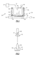
Figure 1 shows an electric power component partially enclosed in a heat pipe. -
Figure 2 schematically shows a method of forming a heat pipe. - A
system 20 is illustrated inFigure 1 and includes acold plate 22 communicating with a heat sink heat exchanger 26. There could be any number of ways of taking heat away from the cold plate, such as a pump or blower, a heat pump, or any other such structure. As known, asurface 39 of aheat pipe 34 is in contact with thecold plate 22 and will draw heat from an electric component (here an inductor 28) and transfer that heat into thecold plate 22. The heat in thecold plate 22 is removed by transport of the heat transfer fluid to the heat sink heat exchanger 26, shown schematically. Theinductor 28 communicates within anelectric system 30 and may include any number of applications such as applications on an aircraft. - The
component 28 is shown as an inductor, but it may be any number of other electronic power components. The outer perimeter of a toroidal inductor is especially suitable to the cup-shaped heat pipe. As shown, a core 31 includescopper wires 32, which are wrapped around acentral core 35. - The
heat pipe 34 may be formed of two planar heat pipe materials which are drawn, spun, or otherwise formed into a cup shape. Seams between pieces may be metallurgically bonded to form a hermetic vessel. This bonding may be by welding or brazing. - A fluid is included in a sealed
cavity 40 and acts to transfer heat from an innerheat pipe face 38 to an outerheat pipe face 136. Alower face 39 of theouter face 136 is in contact with thecold plate 22. Awick 42 is positioned within thecavity 40 and serves to wick the cooling fluid from alower end 142 to anupper end 144. The wick lifts the liquid which was condensed at the cold plate interface by capillary force by having a network of interconnected pores. The wicked surface also covers the inside surface of theinside walls 34a. This porous wick both distributes the condensate over the heated wall, 34a and acts to enhance evaporation. Sintered porous metal or screen matrixes are common constructions but other materials may be used. - Desirably, the
wick 42 is installed so that it is continuous and in direct contact with both the coldlower surface 39 and hotupper surface 52 to effectively convey liquid from one to the other as it transfers heat between thecomponent 28 and thecold plate 22. The fluid essentially evaporates at a hot faceadjacent component 28 and condenses at a cool face adjacent thecold plate 22. - The wick lifts the condensate with capillary force. The height that a liquid can be lifted in a wick is proportional to surface tension of the condensate and inversely proportional to the pore size in the wick material. Also contained in the heat pipe volume is open (non-wicked) space that allows vapor being formed by evaporation in heated regions to migrate to the cooled end of the heat pipe.
- Fluid motion within the heat pipe driven by condensation and evaporation results in a nearly isothermal flow of heat which nearly eliminates the temperature difference that would occur in a solid walled cup.
-
Figure 2 shows a method of forming theheat pipe 34. As shown, two initially flat orplanar portions Wall portions cavity 40. - The wick may be formed of sintered or foam metal which has been developed with small pores for evaporation and capillarity. These materials are available from Thermacore, ACT or other heat pipe vendors.
- The planar
heat pipe materials - Acceptable planar heat pipe materials are available from i2C of Louisville, CO, as Flexible - Conformal Thermal Ground Planes.
- Although an embodiment of this invention has been disclosed, a worker of ordinary skill in this art would recognize that certain modifications would come within the scope of this invention. For that reason, the following claims should be studied to determine the true scope and content of this invention.
Claims (8)
- A cooling system (20) for cooling an electronic component (28) comprising:a heat pipe (34) defined by an inner wall (38) and an outer wall (139) with an intermediate fluid chamber (40), and said heat pipe (34) having a wall (39) to be put in contact with a cold plate (22) and extending away from the cold plate (22) to define a cup shape, with a fluid movement member (42) positioned within the chamber (40) to move the fluid from an end of said chamber (40) adjacent to the cold plate (22) to a spaced end (144) of said cup shape.
- The cooling system as set forth in claim 1, wherein the fluid movement member is a wick (42).
- The cooling system as set forth in claim 1 or 2, wherein the heat pipe (34) has walls formed of planar heat pipe material.
- The cooling system as set forth in claim 1, 2 or 3, wherein the heat pipe (34) is formed of planar heat pipe material.
- An electric system comprising:an electronic component (28); anda cooling system as set forth in any preceding claim, the electronic component received within the cup shaped heat pipe (34), and a wall (39) of said heat pipe (34) in contact with the cold plate (22).
- The electric system as set forth in claim 5, wherein said cold plate (22) communicates with a heat pump (26).
- The electric system as set forth in claim 5 or 6, wherein said cold plate (22) communicates with a heat sink.
- The electric system as set forth in claim 5, 6 or 7, wherein said component (28) is an inductor.
Applications Claiming Priority (1)
| Application Number | Priority Date | Filing Date | Title |
|---|---|---|---|
| US14/525,493 US9723753B2 (en) | 2014-10-28 | 2014-10-28 | Planar heat cup with confined reservoir for electronic power component |
Publications (2)
| Publication Number | Publication Date |
|---|---|
| EP3016139A1 true EP3016139A1 (en) | 2016-05-04 |
| EP3016139B1 EP3016139B1 (en) | 2020-04-29 |
Family
ID=54365000
Family Applications (1)
| Application Number | Title | Priority Date | Filing Date |
|---|---|---|---|
| EP15191163.3A Active EP3016139B1 (en) | 2014-10-28 | 2015-10-23 | Planar heat cup with confined reservoir for electronic power component |
Country Status (2)
| Country | Link |
|---|---|
| US (1) | US9723753B2 (en) |
| EP (1) | EP3016139B1 (en) |
Families Citing this family (4)
| Publication number | Priority date | Publication date | Assignee | Title |
|---|---|---|---|---|
| US10458716B2 (en) | 2014-11-04 | 2019-10-29 | Roccor, Llc | Conformal thermal ground planes |
| CN107978422A (en) * | 2016-10-25 | 2018-05-01 | 特富特科技(深圳)有限公司 | A kind of magnetic device embedding shell mechanism |
| US10804023B2 (en) | 2016-12-15 | 2020-10-13 | Hamilton Sundstrand Corporation | Integrated inductor windings and heat pipes |
| CN106816273A (en) * | 2017-03-06 | 2017-06-09 | 株洲南车奇宏散热技术有限公司 | Heat dissipating method of encapsulation type magnetic element and products thereof |
Citations (4)
| Publication number | Priority date | Publication date | Assignee | Title |
|---|---|---|---|---|
| US20050225943A1 (en) * | 2004-04-07 | 2005-10-13 | Delta Electronics, Inc. | Heat dissipation module |
| US20080122566A1 (en) * | 2006-11-29 | 2008-05-29 | Honeywell International Inc. | Heat pipe supplemented transformer cooling |
| US20130133859A1 (en) * | 2011-11-30 | 2013-05-30 | International Business Machines Corporation | Heat sink with heat bus and fin structure |
| EP2757584A2 (en) * | 2013-01-22 | 2014-07-23 | Palo Alto Research Center Incorporated | Integrated thin film evaporation thermal spreader and planar heat pipe heat sink |
Family Cites Families (16)
| Publication number | Priority date | Publication date | Assignee | Title |
|---|---|---|---|---|
| US20050139995A1 (en) * | 2003-06-10 | 2005-06-30 | David Sarraf | CTE-matched heat pipe |
| US20050099775A1 (en) * | 2003-11-12 | 2005-05-12 | Himanshu Pokharna | Pumped liquid cooling for computer systems using liquid metal coolant |
| US20050145371A1 (en) * | 2003-12-31 | 2005-07-07 | Eric Distefano | Thermal solution for electronics cooling using a heat pipe in combination with active loop solution |
| US7275588B2 (en) | 2004-06-02 | 2007-10-02 | Hul-Chun Hsu | Planar heat pipe structure |
| TW200633628A (en) | 2005-03-10 | 2006-09-16 | Quanta Comp Inc | Second degree curve shape heat pipe and fins heat sink |
| TWM286407U (en) | 2005-10-11 | 2006-01-21 | Augux Co Ltd | Heat dissipation module |
| NL1031206C2 (en) | 2006-02-22 | 2007-08-24 | Thales Nederland Bv | Flat heat pipe for cooling purposes. |
| US8286693B2 (en) * | 2008-04-17 | 2012-10-16 | Aavid Thermalloy, Llc | Heat sink base plate with heat pipe |
| WO2010016890A1 (en) * | 2008-08-04 | 2010-02-11 | Clustered Systems Company | A contact cooled electronic enclosure |
| KR101070842B1 (en) * | 2009-06-11 | 2011-10-06 | 주식회사 자온지 | Heat-dissipating device and electronic apparatus having the same |
| US8203410B2 (en) | 2010-03-03 | 2012-06-19 | Honeywell International Inc. | Inductor assembly |
| CN102231542B (en) * | 2011-06-24 | 2014-05-07 | 台达电子企业管理(上海)有限公司 | Battery charging device for electric vehicles |
| US20130257574A1 (en) | 2012-04-03 | 2013-10-03 | Hamilton Sundstrand Corporation | Immersion cooled toroid inductor assembly |
| US8680959B2 (en) | 2012-05-09 | 2014-03-25 | Hamilton Sundstrand Corporation | Immersion cooled inductor apparatus |
| US9042097B2 (en) * | 2012-05-17 | 2015-05-26 | Hamilton Sundstrand Corporation | Two-phase electronic component cooling arrangement |
| US20150013941A1 (en) * | 2013-07-10 | 2015-01-15 | Emerson Network Power - Embedded Computing, Inc. | Conduction Cooled Chassis With Embedded Heatpipes |
-
2014
- 2014-10-28 US US14/525,493 patent/US9723753B2/en active Active
-
2015
- 2015-10-23 EP EP15191163.3A patent/EP3016139B1/en active Active
Patent Citations (4)
| Publication number | Priority date | Publication date | Assignee | Title |
|---|---|---|---|---|
| US20050225943A1 (en) * | 2004-04-07 | 2005-10-13 | Delta Electronics, Inc. | Heat dissipation module |
| US20080122566A1 (en) * | 2006-11-29 | 2008-05-29 | Honeywell International Inc. | Heat pipe supplemented transformer cooling |
| US20130133859A1 (en) * | 2011-11-30 | 2013-05-30 | International Business Machines Corporation | Heat sink with heat bus and fin structure |
| EP2757584A2 (en) * | 2013-01-22 | 2014-07-23 | Palo Alto Research Center Incorporated | Integrated thin film evaporation thermal spreader and planar heat pipe heat sink |
Also Published As
| Publication number | Publication date |
|---|---|
| US20160120066A1 (en) | 2016-04-28 |
| EP3016139B1 (en) | 2020-04-29 |
| US9723753B2 (en) | 2017-08-01 |
Similar Documents
| Publication | Publication Date | Title |
|---|---|---|
| US9459050B2 (en) | Heat pipe system | |
| EP3016139B1 (en) | Planar heat cup with confined reservoir for electronic power component | |
| US10514211B2 (en) | Vapor chamber | |
| US20120227935A1 (en) | Interconnected heat pipe assembly and method for manufacturing the same | |
| US11598586B2 (en) | Heat transfer device | |
| CN203432427U (en) | Vapor structure | |
| US10240873B2 (en) | Joint assembly of vapor chambers | |
| CN104976909A (en) | Vapor structure and manufacturing method thereof | |
| CN107289800A (en) | Temperature equalizing plate structure and manufacturing method thereof | |
| US8516700B2 (en) | Method for manufacturing flat plate heat pipe | |
| US7949236B2 (en) | Home heating radiator using a phase change heat transfer fluid | |
| CN105246302B (en) | A kind of heat-pipe radiating apparatus | |
| JP4998933B2 (en) | Heat transfer system | |
| Wits et al. | Experimental performance of a 3D-Printed hybrid heat pipe-thermosyphon for cooling of power electronics | |
| CN100366998C (en) | A Planar Capillary Wick Condenser for Capillary Suction Two-Phase Fluid Circuit | |
| US20120037344A1 (en) | Flat heat pipe having swirl core | |
| CN108317878B (en) | A kind of loop heat pipe evaporator | |
| CN206556483U (en) | Heat-pipe radiator | |
| CN206559796U (en) | Heat-pipe radiator | |
| KR20180101566A (en) | Vibrating Mini-Channel Cooker | |
| US20020074108A1 (en) | Horizontal two-phase loop thermosyphon with capillary structures | |
| US9421648B2 (en) | Manufacturing method of heat pipe structure | |
| CN206556482U (en) | Heat-pipe radiator | |
| JP2012013277A (en) | Heat sink | |
| CN206556481U (en) | Heat-pipe radiator |
Legal Events
| Date | Code | Title | Description |
|---|---|---|---|
| PUAI | Public reference made under article 153(3) epc to a published international application that has entered the european phase |
Free format text: ORIGINAL CODE: 0009012 |
|
| AK | Designated contracting states |
Kind code of ref document: A1 Designated state(s): AL AT BE BG CH CY CZ DE DK EE ES FI FR GB GR HR HU IE IS IT LI LT LU LV MC MK MT NL NO PL PT RO RS SE SI SK SM TR |
|
| AX | Request for extension of the european patent |
Extension state: BA ME |
|
| STAA | Information on the status of an ep patent application or granted ep patent |
Free format text: STATUS: REQUEST FOR EXAMINATION WAS MADE |
|
| 17P | Request for examination filed |
Effective date: 20161104 |
|
| RBV | Designated contracting states (corrected) |
Designated state(s): AL AT BE BG CH CY CZ DE DK EE ES FI FR GB GR HR HU IE IS IT LI LT LU LV MC MK MT NL NO PL PT RO RS SE SI SK SM TR |
|
| STAA | Information on the status of an ep patent application or granted ep patent |
Free format text: STATUS: EXAMINATION IS IN PROGRESS |
|
| 17Q | First examination report despatched |
Effective date: 20170317 |
|
| RAP1 | Party data changed (applicant data changed or rights of an application transferred) |
Owner name: HAMILTON SUNDSTRAND CORPORATION |
|
| GRAP | Despatch of communication of intention to grant a patent |
Free format text: ORIGINAL CODE: EPIDOSNIGR1 |
|
| STAA | Information on the status of an ep patent application or granted ep patent |
Free format text: STATUS: GRANT OF PATENT IS INTENDED |
|
| GRAJ | Information related to disapproval of communication of intention to grant by the applicant or resumption of examination proceedings by the epo deleted |
Free format text: ORIGINAL CODE: EPIDOSDIGR1 |
|
| STAA | Information on the status of an ep patent application or granted ep patent |
Free format text: STATUS: EXAMINATION IS IN PROGRESS |
|
| GRAP | Despatch of communication of intention to grant a patent |
Free format text: ORIGINAL CODE: EPIDOSNIGR1 |
|
| STAA | Information on the status of an ep patent application or granted ep patent |
Free format text: STATUS: GRANT OF PATENT IS INTENDED |
|
| INTG | Intention to grant announced |
Effective date: 20191202 |
|
| INTG | Intention to grant announced |
Effective date: 20191211 |
|
| GRAS | Grant fee paid |
Free format text: ORIGINAL CODE: EPIDOSNIGR3 |
|
| GRAA | (expected) grant |
Free format text: ORIGINAL CODE: 0009210 |
|
| STAA | Information on the status of an ep patent application or granted ep patent |
Free format text: STATUS: THE PATENT HAS BEEN GRANTED |
|
| AK | Designated contracting states |
Kind code of ref document: B1 Designated state(s): AL AT BE BG CH CY CZ DE DK EE ES FI FR GB GR HR HU IE IS IT LI LT LU LV MC MK MT NL NO PL PT RO RS SE SI SK SM TR |
|
| REG | Reference to a national code |
Ref country code: GB Ref legal event code: FG4D |
|
| REG | Reference to a national code |
Ref country code: CH Ref legal event code: EP |
|
| REG | Reference to a national code |
Ref country code: AT Ref legal event code: REF Ref document number: 1264570 Country of ref document: AT Kind code of ref document: T Effective date: 20200515 |
|
| REG | Reference to a national code |
Ref country code: DE Ref legal event code: R096 Ref document number: 602015051531 Country of ref document: DE |
|
| REG | Reference to a national code |
Ref country code: IE Ref legal event code: FG4D |
|
| REG | Reference to a national code |
Ref country code: NL Ref legal event code: MP Effective date: 20200429 |
|
| REG | Reference to a national code |
Ref country code: LT Ref legal event code: MG4D |
|
| PG25 | Lapsed in a contracting state [announced via postgrant information from national office to epo] |
Ref country code: GR Free format text: LAPSE BECAUSE OF FAILURE TO SUBMIT A TRANSLATION OF THE DESCRIPTION OR TO PAY THE FEE WITHIN THE PRESCRIBED TIME-LIMIT Effective date: 20200730 Ref country code: LT Free format text: LAPSE BECAUSE OF FAILURE TO SUBMIT A TRANSLATION OF THE DESCRIPTION OR TO PAY THE FEE WITHIN THE PRESCRIBED TIME-LIMIT Effective date: 20200429 Ref country code: FI Free format text: LAPSE BECAUSE OF FAILURE TO SUBMIT A TRANSLATION OF THE DESCRIPTION OR TO PAY THE FEE WITHIN THE PRESCRIBED TIME-LIMIT Effective date: 20200429 Ref country code: IS Free format text: LAPSE BECAUSE OF FAILURE TO SUBMIT A TRANSLATION OF THE DESCRIPTION OR TO PAY THE FEE WITHIN THE PRESCRIBED TIME-LIMIT Effective date: 20200829 Ref country code: SE Free format text: LAPSE BECAUSE OF FAILURE TO SUBMIT A TRANSLATION OF THE DESCRIPTION OR TO PAY THE FEE WITHIN THE PRESCRIBED TIME-LIMIT Effective date: 20200429 Ref country code: NO Free format text: LAPSE BECAUSE OF FAILURE TO SUBMIT A TRANSLATION OF THE DESCRIPTION OR TO PAY THE FEE WITHIN THE PRESCRIBED TIME-LIMIT Effective date: 20200729 Ref country code: PT Free format text: LAPSE BECAUSE OF FAILURE TO SUBMIT A TRANSLATION OF THE DESCRIPTION OR TO PAY THE FEE WITHIN THE PRESCRIBED TIME-LIMIT Effective date: 20200831 |
|
| REG | Reference to a national code |
Ref country code: AT Ref legal event code: MK05 Ref document number: 1264570 Country of ref document: AT Kind code of ref document: T Effective date: 20200429 |
|
| PG25 | Lapsed in a contracting state [announced via postgrant information from national office to epo] |
Ref country code: BG Free format text: LAPSE BECAUSE OF FAILURE TO SUBMIT A TRANSLATION OF THE DESCRIPTION OR TO PAY THE FEE WITHIN THE PRESCRIBED TIME-LIMIT Effective date: 20200729 Ref country code: HR Free format text: LAPSE BECAUSE OF FAILURE TO SUBMIT A TRANSLATION OF THE DESCRIPTION OR TO PAY THE FEE WITHIN THE PRESCRIBED TIME-LIMIT Effective date: 20200429 Ref country code: RS Free format text: LAPSE BECAUSE OF FAILURE TO SUBMIT A TRANSLATION OF THE DESCRIPTION OR TO PAY THE FEE WITHIN THE PRESCRIBED TIME-LIMIT Effective date: 20200429 Ref country code: LV Free format text: LAPSE BECAUSE OF FAILURE TO SUBMIT A TRANSLATION OF THE DESCRIPTION OR TO PAY THE FEE WITHIN THE PRESCRIBED TIME-LIMIT Effective date: 20200429 |
|
| PG25 | Lapsed in a contracting state [announced via postgrant information from national office to epo] |
Ref country code: AL Free format text: LAPSE BECAUSE OF FAILURE TO SUBMIT A TRANSLATION OF THE DESCRIPTION OR TO PAY THE FEE WITHIN THE PRESCRIBED TIME-LIMIT Effective date: 20200429 Ref country code: NL Free format text: LAPSE BECAUSE OF FAILURE TO SUBMIT A TRANSLATION OF THE DESCRIPTION OR TO PAY THE FEE WITHIN THE PRESCRIBED TIME-LIMIT Effective date: 20200429 |
|
| PG25 | Lapsed in a contracting state [announced via postgrant information from national office to epo] |
Ref country code: EE Free format text: LAPSE BECAUSE OF FAILURE TO SUBMIT A TRANSLATION OF THE DESCRIPTION OR TO PAY THE FEE WITHIN THE PRESCRIBED TIME-LIMIT Effective date: 20200429 Ref country code: AT Free format text: LAPSE BECAUSE OF FAILURE TO SUBMIT A TRANSLATION OF THE DESCRIPTION OR TO PAY THE FEE WITHIN THE PRESCRIBED TIME-LIMIT Effective date: 20200429 Ref country code: SM Free format text: LAPSE BECAUSE OF FAILURE TO SUBMIT A TRANSLATION OF THE DESCRIPTION OR TO PAY THE FEE WITHIN THE PRESCRIBED TIME-LIMIT Effective date: 20200429 Ref country code: DK Free format text: LAPSE BECAUSE OF FAILURE TO SUBMIT A TRANSLATION OF THE DESCRIPTION OR TO PAY THE FEE WITHIN THE PRESCRIBED TIME-LIMIT Effective date: 20200429 Ref country code: ES Free format text: LAPSE BECAUSE OF FAILURE TO SUBMIT A TRANSLATION OF THE DESCRIPTION OR TO PAY THE FEE WITHIN THE PRESCRIBED TIME-LIMIT Effective date: 20200429 Ref country code: RO Free format text: LAPSE BECAUSE OF FAILURE TO SUBMIT A TRANSLATION OF THE DESCRIPTION OR TO PAY THE FEE WITHIN THE PRESCRIBED TIME-LIMIT Effective date: 20200429 Ref country code: CZ Free format text: LAPSE BECAUSE OF FAILURE TO SUBMIT A TRANSLATION OF THE DESCRIPTION OR TO PAY THE FEE WITHIN THE PRESCRIBED TIME-LIMIT Effective date: 20200429 Ref country code: IT Free format text: LAPSE BECAUSE OF FAILURE TO SUBMIT A TRANSLATION OF THE DESCRIPTION OR TO PAY THE FEE WITHIN THE PRESCRIBED TIME-LIMIT Effective date: 20200429 |
|
| REG | Reference to a national code |
Ref country code: DE Ref legal event code: R097 Ref document number: 602015051531 Country of ref document: DE |
|
| PG25 | Lapsed in a contracting state [announced via postgrant information from national office to epo] |
Ref country code: PL Free format text: LAPSE BECAUSE OF FAILURE TO SUBMIT A TRANSLATION OF THE DESCRIPTION OR TO PAY THE FEE WITHIN THE PRESCRIBED TIME-LIMIT Effective date: 20200429 Ref country code: SK Free format text: LAPSE BECAUSE OF FAILURE TO SUBMIT A TRANSLATION OF THE DESCRIPTION OR TO PAY THE FEE WITHIN THE PRESCRIBED TIME-LIMIT Effective date: 20200429 |
|
| PLBE | No opposition filed within time limit |
Free format text: ORIGINAL CODE: 0009261 |
|
| STAA | Information on the status of an ep patent application or granted ep patent |
Free format text: STATUS: NO OPPOSITION FILED WITHIN TIME LIMIT |
|
| 26N | No opposition filed |
Effective date: 20210201 |
|
| PG25 | Lapsed in a contracting state [announced via postgrant information from national office to epo] |
Ref country code: SI Free format text: LAPSE BECAUSE OF FAILURE TO SUBMIT A TRANSLATION OF THE DESCRIPTION OR TO PAY THE FEE WITHIN THE PRESCRIBED TIME-LIMIT Effective date: 20200429 |
|
| REG | Reference to a national code |
Ref country code: CH Ref legal event code: PL |
|
| PG25 | Lapsed in a contracting state [announced via postgrant information from national office to epo] |
Ref country code: LU Free format text: LAPSE BECAUSE OF NON-PAYMENT OF DUE FEES Effective date: 20201023 Ref country code: MC Free format text: LAPSE BECAUSE OF FAILURE TO SUBMIT A TRANSLATION OF THE DESCRIPTION OR TO PAY THE FEE WITHIN THE PRESCRIBED TIME-LIMIT Effective date: 20200429 |
|
| REG | Reference to a national code |
Ref country code: BE Ref legal event code: MM Effective date: 20201031 |
|
| PG25 | Lapsed in a contracting state [announced via postgrant information from national office to epo] |
Ref country code: CH Free format text: LAPSE BECAUSE OF NON-PAYMENT OF DUE FEES Effective date: 20201031 Ref country code: BE Free format text: LAPSE BECAUSE OF NON-PAYMENT OF DUE FEES Effective date: 20201031 Ref country code: LI Free format text: LAPSE BECAUSE OF NON-PAYMENT OF DUE FEES Effective date: 20201031 |
|
| PG25 | Lapsed in a contracting state [announced via postgrant information from national office to epo] |
Ref country code: IE Free format text: LAPSE BECAUSE OF NON-PAYMENT OF DUE FEES Effective date: 20201023 |
|
| PG25 | Lapsed in a contracting state [announced via postgrant information from national office to epo] |
Ref country code: TR Free format text: LAPSE BECAUSE OF FAILURE TO SUBMIT A TRANSLATION OF THE DESCRIPTION OR TO PAY THE FEE WITHIN THE PRESCRIBED TIME-LIMIT Effective date: 20200429 Ref country code: MT Free format text: LAPSE BECAUSE OF FAILURE TO SUBMIT A TRANSLATION OF THE DESCRIPTION OR TO PAY THE FEE WITHIN THE PRESCRIBED TIME-LIMIT Effective date: 20200429 Ref country code: CY Free format text: LAPSE BECAUSE OF FAILURE TO SUBMIT A TRANSLATION OF THE DESCRIPTION OR TO PAY THE FEE WITHIN THE PRESCRIBED TIME-LIMIT Effective date: 20200429 |
|
| PG25 | Lapsed in a contracting state [announced via postgrant information from national office to epo] |
Ref country code: MK Free format text: LAPSE BECAUSE OF FAILURE TO SUBMIT A TRANSLATION OF THE DESCRIPTION OR TO PAY THE FEE WITHIN THE PRESCRIBED TIME-LIMIT Effective date: 20200429 |
|
| P01 | Opt-out of the competence of the unified patent court (upc) registered |
Effective date: 20230522 |
|
| PGFP | Annual fee paid to national office [announced via postgrant information from national office to epo] |
Ref country code: GB Payment date: 20250923 Year of fee payment: 11 |
|
| PGFP | Annual fee paid to national office [announced via postgrant information from national office to epo] |
Ref country code: FR Payment date: 20250924 Year of fee payment: 11 |
|
| REG | Reference to a national code |
Ref country code: DE Ref legal event code: R079 Ref document number: 602015051531 Country of ref document: DE Free format text: PREVIOUS MAIN CLASS: H01L0023427000 Ipc: H10W0040730000 |
|
| PGFP | Annual fee paid to national office [announced via postgrant information from national office to epo] |
Ref country code: DE Payment date: 20250923 Year of fee payment: 11 |