EP3015791A1 - Centrifugeuse dotée d'un circuit de refroidissement de compresseur et procédé de fonctionnement d'une centrifugeuse dotée d'un circuit de refroidissement de compresseur - Google Patents
Centrifugeuse dotée d'un circuit de refroidissement de compresseur et procédé de fonctionnement d'une centrifugeuse dotée d'un circuit de refroidissement de compresseur Download PDFInfo
- Publication number
- EP3015791A1 EP3015791A1 EP14003658.3A EP14003658A EP3015791A1 EP 3015791 A1 EP3015791 A1 EP 3015791A1 EP 14003658 A EP14003658 A EP 14003658A EP 3015791 A1 EP3015791 A1 EP 3015791A1
- Authority
- EP
- European Patent Office
- Prior art keywords
- centrifuge
- compressor
- refrigerant
- cooling circuit
- pressure
- Prior art date
- Legal status (The legal status is an assumption and is not a legal conclusion. Google has not performed a legal analysis and makes no representation as to the accuracy of the status listed.)
- Withdrawn
Links
Images

Classifications
-
- F—MECHANICAL ENGINEERING; LIGHTING; HEATING; WEAPONS; BLASTING
- F25—REFRIGERATION OR COOLING; COMBINED HEATING AND REFRIGERATION SYSTEMS; HEAT PUMP SYSTEMS; MANUFACTURE OR STORAGE OF ICE; LIQUEFACTION SOLIDIFICATION OF GASES
- F25B—REFRIGERATION MACHINES, PLANTS OR SYSTEMS; COMBINED HEATING AND REFRIGERATION SYSTEMS; HEAT PUMP SYSTEMS
- F25B9/00—Compression machines, plants or systems, in which the refrigerant is air or other gas of low boiling point
- F25B9/002—Compression machines, plants or systems, in which the refrigerant is air or other gas of low boiling point characterised by the refrigerant
- F25B9/008—Compression machines, plants or systems, in which the refrigerant is air or other gas of low boiling point characterised by the refrigerant the refrigerant being carbon dioxide
-
- B—PERFORMING OPERATIONS; TRANSPORTING
- B04—CENTRIFUGAL APPARATUS OR MACHINES FOR CARRYING-OUT PHYSICAL OR CHEMICAL PROCESSES
- B04B—CENTRIFUGES
- B04B15/00—Other accessories for centrifuges
- B04B15/02—Other accessories for centrifuges for cooling, heating, or heat insulating
-
- F—MECHANICAL ENGINEERING; LIGHTING; HEATING; WEAPONS; BLASTING
- F25—REFRIGERATION OR COOLING; COMBINED HEATING AND REFRIGERATION SYSTEMS; HEAT PUMP SYSTEMS; MANUFACTURE OR STORAGE OF ICE; LIQUEFACTION SOLIDIFICATION OF GASES
- F25B—REFRIGERATION MACHINES, PLANTS OR SYSTEMS; COMBINED HEATING AND REFRIGERATION SYSTEMS; HEAT PUMP SYSTEMS
- F25B41/00—Fluid-circulation arrangements
- F25B41/30—Expansion means; Dispositions thereof
- F25B41/37—Capillary tubes
-
- F—MECHANICAL ENGINEERING; LIGHTING; HEATING; WEAPONS; BLASTING
- F25—REFRIGERATION OR COOLING; COMBINED HEATING AND REFRIGERATION SYSTEMS; HEAT PUMP SYSTEMS; MANUFACTURE OR STORAGE OF ICE; LIQUEFACTION SOLIDIFICATION OF GASES
- F25B—REFRIGERATION MACHINES, PLANTS OR SYSTEMS; COMBINED HEATING AND REFRIGERATION SYSTEMS; HEAT PUMP SYSTEMS
- F25B41/00—Fluid-circulation arrangements
- F25B41/30—Expansion means; Dispositions thereof
- F25B41/385—Dispositions with two or more expansion means arranged in parallel on a refrigerant line leading to the same evaporator
-
- F—MECHANICAL ENGINEERING; LIGHTING; HEATING; WEAPONS; BLASTING
- F25—REFRIGERATION OR COOLING; COMBINED HEATING AND REFRIGERATION SYSTEMS; HEAT PUMP SYSTEMS; MANUFACTURE OR STORAGE OF ICE; LIQUEFACTION SOLIDIFICATION OF GASES
- F25B—REFRIGERATION MACHINES, PLANTS OR SYSTEMS; COMBINED HEATING AND REFRIGERATION SYSTEMS; HEAT PUMP SYSTEMS
- F25B49/00—Arrangement or mounting of control or safety devices
- F25B49/02—Arrangement or mounting of control or safety devices for compression type machines, plants or systems
-
- F—MECHANICAL ENGINEERING; LIGHTING; HEATING; WEAPONS; BLASTING
- F25—REFRIGERATION OR COOLING; COMBINED HEATING AND REFRIGERATION SYSTEMS; HEAT PUMP SYSTEMS; MANUFACTURE OR STORAGE OF ICE; LIQUEFACTION SOLIDIFICATION OF GASES
- F25B—REFRIGERATION MACHINES, PLANTS OR SYSTEMS; COMBINED HEATING AND REFRIGERATION SYSTEMS; HEAT PUMP SYSTEMS
- F25B2341/00—Details of ejectors not being used as compression device; Details of flow restrictors or expansion valves
- F25B2341/06—Details of flow restrictors or expansion valves
- F25B2341/062—Capillary expansion valves
-
- F—MECHANICAL ENGINEERING; LIGHTING; HEATING; WEAPONS; BLASTING
- F25—REFRIGERATION OR COOLING; COMBINED HEATING AND REFRIGERATION SYSTEMS; HEAT PUMP SYSTEMS; MANUFACTURE OR STORAGE OF ICE; LIQUEFACTION SOLIDIFICATION OF GASES
- F25B—REFRIGERATION MACHINES, PLANTS OR SYSTEMS; COMBINED HEATING AND REFRIGERATION SYSTEMS; HEAT PUMP SYSTEMS
- F25B2400/00—General features or devices for refrigeration machines, plants or systems, combined heating and refrigeration systems or heat-pump systems, i.e. not limited to a particular subgroup of F25B
- F25B2400/04—Refrigeration circuit bypassing means
- F25B2400/0409—Refrigeration circuit bypassing means for the evaporator
-
- F—MECHANICAL ENGINEERING; LIGHTING; HEATING; WEAPONS; BLASTING
- F25—REFRIGERATION OR COOLING; COMBINED HEATING AND REFRIGERATION SYSTEMS; HEAT PUMP SYSTEMS; MANUFACTURE OR STORAGE OF ICE; LIQUEFACTION SOLIDIFICATION OF GASES
- F25B—REFRIGERATION MACHINES, PLANTS OR SYSTEMS; COMBINED HEATING AND REFRIGERATION SYSTEMS; HEAT PUMP SYSTEMS
- F25B2400/00—General features or devices for refrigeration machines, plants or systems, combined heating and refrigeration systems or heat-pump systems, i.e. not limited to a particular subgroup of F25B
- F25B2400/04—Refrigeration circuit bypassing means
- F25B2400/0411—Refrigeration circuit bypassing means for the expansion valve or capillary tube
-
- F—MECHANICAL ENGINEERING; LIGHTING; HEATING; WEAPONS; BLASTING
- F25—REFRIGERATION OR COOLING; COMBINED HEATING AND REFRIGERATION SYSTEMS; HEAT PUMP SYSTEMS; MANUFACTURE OR STORAGE OF ICE; LIQUEFACTION SOLIDIFICATION OF GASES
- F25B—REFRIGERATION MACHINES, PLANTS OR SYSTEMS; COMBINED HEATING AND REFRIGERATION SYSTEMS; HEAT PUMP SYSTEMS
- F25B2500/00—Problems to be solved
- F25B2500/26—Problems to be solved characterised by the startup of the refrigeration cycle
-
- F—MECHANICAL ENGINEERING; LIGHTING; HEATING; WEAPONS; BLASTING
- F25—REFRIGERATION OR COOLING; COMBINED HEATING AND REFRIGERATION SYSTEMS; HEAT PUMP SYSTEMS; MANUFACTURE OR STORAGE OF ICE; LIQUEFACTION SOLIDIFICATION OF GASES
- F25B—REFRIGERATION MACHINES, PLANTS OR SYSTEMS; COMBINED HEATING AND REFRIGERATION SYSTEMS; HEAT PUMP SYSTEMS
- F25B2600/00—Control issues
- F25B2600/02—Compressor control
- F25B2600/027—Compressor control by controlling pressure
- F25B2600/0271—Compressor control by controlling pressure the discharge pressure
-
- F—MECHANICAL ENGINEERING; LIGHTING; HEATING; WEAPONS; BLASTING
- F25—REFRIGERATION OR COOLING; COMBINED HEATING AND REFRIGERATION SYSTEMS; HEAT PUMP SYSTEMS; MANUFACTURE OR STORAGE OF ICE; LIQUEFACTION SOLIDIFICATION OF GASES
- F25B—REFRIGERATION MACHINES, PLANTS OR SYSTEMS; COMBINED HEATING AND REFRIGERATION SYSTEMS; HEAT PUMP SYSTEMS
- F25B2600/00—Control issues
- F25B2600/25—Control of valves
- F25B2600/2513—Expansion valves
-
- F—MECHANICAL ENGINEERING; LIGHTING; HEATING; WEAPONS; BLASTING
- F25—REFRIGERATION OR COOLING; COMBINED HEATING AND REFRIGERATION SYSTEMS; HEAT PUMP SYSTEMS; MANUFACTURE OR STORAGE OF ICE; LIQUEFACTION SOLIDIFICATION OF GASES
- F25B—REFRIGERATION MACHINES, PLANTS OR SYSTEMS; COMBINED HEATING AND REFRIGERATION SYSTEMS; HEAT PUMP SYSTEMS
- F25B2700/00—Sensing or detecting of parameters; Sensors therefor
- F25B2700/19—Pressures
- F25B2700/193—Pressures of the compressor
-
- F—MECHANICAL ENGINEERING; LIGHTING; HEATING; WEAPONS; BLASTING
- F25—REFRIGERATION OR COOLING; COMBINED HEATING AND REFRIGERATION SYSTEMS; HEAT PUMP SYSTEMS; MANUFACTURE OR STORAGE OF ICE; LIQUEFACTION SOLIDIFICATION OF GASES
- F25B—REFRIGERATION MACHINES, PLANTS OR SYSTEMS; COMBINED HEATING AND REFRIGERATION SYSTEMS; HEAT PUMP SYSTEMS
- F25B2700/00—Sensing or detecting of parameters; Sensors therefor
- F25B2700/21—Temperatures
- F25B2700/2106—Temperatures of fresh outdoor air
-
- F—MECHANICAL ENGINEERING; LIGHTING; HEATING; WEAPONS; BLASTING
- F25—REFRIGERATION OR COOLING; COMBINED HEATING AND REFRIGERATION SYSTEMS; HEAT PUMP SYSTEMS; MANUFACTURE OR STORAGE OF ICE; LIQUEFACTION SOLIDIFICATION OF GASES
- F25B—REFRIGERATION MACHINES, PLANTS OR SYSTEMS; COMBINED HEATING AND REFRIGERATION SYSTEMS; HEAT PUMP SYSTEMS
- F25B2700/00—Sensing or detecting of parameters; Sensors therefor
- F25B2700/21—Temperatures
- F25B2700/2116—Temperatures of a condenser
-
- F—MECHANICAL ENGINEERING; LIGHTING; HEATING; WEAPONS; BLASTING
- F25—REFRIGERATION OR COOLING; COMBINED HEATING AND REFRIGERATION SYSTEMS; HEAT PUMP SYSTEMS; MANUFACTURE OR STORAGE OF ICE; LIQUEFACTION SOLIDIFICATION OF GASES
- F25B—REFRIGERATION MACHINES, PLANTS OR SYSTEMS; COMBINED HEATING AND REFRIGERATION SYSTEMS; HEAT PUMP SYSTEMS
- F25B40/00—Subcoolers, desuperheaters or superheaters
Definitions
- the present invention relates to a centrifuge with a compressor cooling circuit according to the preamble of claim 1 and a method for operating a centrifuge with a compressor cooling circuit according to the preamble of claim 10.
- Centrifuges in particular laboratory centrifuges, are used to separate the components of samples centrifuged therein by utilizing the inertia of the mass. In the process, ever higher rotational speeds are used to achieve high separation rates. However, this results in a relatively high heat, which must be dissipated again by suitable cooling methods, for example, not to adversely affect the samples to be centrifuged.
- compressor cooling circuits In order to avoid overheating or to maintain certain sample temperatures in the centrifugation, especially indirect active cooling systems are used, which have a refrigerant circuit, which tempered the centrifuge tank, wherein the active cooling takes place by means of a compressor. Such refrigerant circuits are hereinafter referred to as "compressor cooling circuits”.
- the second variant is associated with a higher energy consumption and thus higher maintenance costs.
- the object of the present invention is to provide a solution with which the abovementioned disadvantages are avoided.
- the necessary space in existing centrifuges should not be increased.
- the present object can be achieved in a surprisingly simple and cost-effective manner, if the refrigerant used is not the commonly used refrigerant 1,1,1,2-tetrafluoroethane (R-134a), but CO 2 (R-134a). 744) and / or at least one hydrocarbon is used. It can be used not only pure refrigerant, but also mixtures.
- compressor cooling circuits of centrifuges have a much higher efficiency, so that they can be operated either at lower power consumption to achieve the same cooling performance as previous compressor cooling circuits such centrifuges, or it can be achieved at the same power lower cooling temperatures and a larger heat in dominate the centrifuges.
- a positive side effect of the present invention is that the refrigerants used according to the invention R-744 and hydrocarbons such as propane (R-290), propene (R-1270), butane (R-600) and isobutane (R-600a) is not recycled because they are naturally occurring substances. Thus, no greenhouse effect is associated with the possible release of the refrigerant, since these refrigerants were taken from nature.
- hydrocarbons such as propane (R-290), propene (R-1270), butane (R-600) and isobutane (R-600a)
- the centrifuge according to the invention in particular laboratory centrifuge, with a compressor cooling circuit having an external heat exchanger, an evaporator, a compressor and a refrigerant line, a centrifuge rotor, which is driven by a centrifuge motor, and a centrifuge container, which is cooled by means of the compressor cooling circuit, so distinguished in that the refrigerant of the compressor cooling circuit comprises at least one of carbon dioxide and hydrocarbons.
- the external heat exchanger is not a condenser, but a gas cooler.
- the task of the gas cooler is to cool and partially liquefy the gas, since it is in a supercritical state, which is why the gas cooler must have a corresponding area.
- the refrigerant comprises at least one substance from the group propane, propene, butane and isobutane. These are in addition to CO 2 particularly easy and inexpensive to procure and lead to a high efficiency.
- the compressor cooling circuit has an injection system arranged upstream of the evaporator, which serves as a throttle and depressurizes the refrigerant via a pressure change, wherein an injection means, preferably as an electronic injection valve or as at least a first, preferably a parallel connected first and a second capillary tube is, is provided, wherein the second capillary tube is formed in particular switched on and off.
- an injection means preferably as an electronic injection valve or as at least a first, preferably a parallel connected first and a second capillary tube is, is provided, wherein the second capillary tube is formed in particular switched on and off.
- the first capillary tube has a length in the range of 3.0 m to 0.5 m, preferably in the range of 2.5 m to 1.9 m, in particular 1.7 m and an inner diameter in the range 0.3 mm to 1 mm, preferably in the range of 0.5 mm to 0.7 mm, in particular of 0.6 mm, and / or the second capillary tube has a length in the range of 1.5 m to 0.5 m, preferably in the range 1, 2 m to 0.8 m, in particular of 1.0 m and an inner diameter in the range 0.5 mm to 1.2 mm, preferably in the range 0.7 mm to 0.9 mm, in particular of 0.8 mm and / or the at least one capillary tube has an outer diameter in the range of 1.0 mm to 3 mm, preferably in the range of 1.5 mm to 2.5 mm, in particular 2 mm.
- This injection system is particularly well adapted to the refrigerant according to the invention, in particular to R-7
- an internal heat exchanger is arranged in the compressor cooling circuit, which allows heat transfer between two areas of the refrigerant line, preferably a first area of the refrigerant line between the evaporator and compressor and a second area of the refrigerant line between the external heat exchanger and injector , wherein in particular it is provided that the internal heat exchanger is designed as two pipe sections guided into each other.
- an inner tube having an inner diameter of 6 mm and a wall thickness of 1 mm is used on the high-pressure side
- an outer tube is used with an inner diameter of 10 mm and a wall thickness of 1 mm.
- the length of the internal heat exchanger is preferably in the range 0.5 m to 2.5 m, preferably in the range 1.0 m to 2.0 m and is in particular 1.5 m.
- the refrigerant is further heated before it enters the compressor, and on the other hand, the heat that is absorbed before the compressor, the external heat exchanger or the gas cooler removed before the refrigerant flows into the injection system. This is associated with an improvement in the efficiency. In addition, this also a return of liquid refrigerant in the compressor, which can lead to so-called "liquid shocks" avoided.
- At least one bypass for bridging the internal heat exchanger exist, preferably two bypasses for bridging the internal heat exchanger consist, wherein the first bypass in the first region and the second bypass is provided in the second region of the refrigerant line.
- the internal heat exchanger is switched off and switched on and adjustable, so that an easily achievable adaptation of the compressor cooling circuit to various working conditions is possible.
- an expansion vessel or refrigerant collector is arranged upstream of the evaporator, preferably in front of the injection system, the supply line is particularly lockable and / or that there is a bypass, the coolant to the compressor and before the external heat exchanger subtracts and the evaporator and / or that before the evaporator and after the external heat exchanger, a security institution, preferably in the form of a safety valve, is arranged.
- these elements can also be arranged at other locations in the coolant circuit, but these locations are preferred.
- the amount of refrigerant can be adapted to the needs, so for example adapted to the ambient temperature.
- bypass which is a hot gas bypass
- warm refrigerant is supplied to the evaporator, whereby ice formation, for example at the triple point of CO 2 in the evaporator can be avoided.
- a bypass controllable in terms of refrigerant flow which is regulated as a function of the temperature in the suction line of the compressor.
- the bypass is used in partial load operation.
- the compressor is down-regulated or the injection system is opened, which in turn is suitably regulated as a function of the temperature in the suction line of the compressor.
- a cooling cascade can also be used in such a way that the CO 2 -based compressor cooling circuit, for example, is cooled down by means of a further cooling circuit in order to prevent critical pressure increases in the compressor cooling circuit.
- the compressor pressure is controlled as a function of at least one of the temperatures of the external heat exchanger and the ambient temperature.
- the pressures are preferably about 50-70 bar for about 10 ° C ambient temperature, about 75-90 bar for about 23 ° C ambient temperature and about 105-130 bar for about 40 ° C ambient temperature.
- the centrifuge according to the invention is used with particular advantage.
- the injection system When operating the centrifuge injection system at a higher throughput upon reaching a first compressor pressure, the injection system operates at a lower flow rate when decreasing to a second compressor pressure that is less than the first compressor pressure and the injection system again when the first compressor pressure is reached In turn, at the higher throughput is operated, then safety-related pressure increases can be avoided and it is the efficiency of the compressor cooling circuit increases.
- pressure switch points of 86 bar for the first compressor pressure and 82 bar for the second compressor pressure and in a second variant pressure switch points of 105 bar for the first compressor pressure and 100 bar for the second compressor pressure are preferred.
- the injection system for example in the form of an electronic injection valve or in the form of two capillary tubes, is operated at a higher throughput at the start of the centrifuge in order to achieve rapid cooling, but also to high pressure to avoid.
- a good evaporator utilization is achieved and the evaporator itself cooled quickly. Only later should the throughput in favor of a low evaporation temperature, and thus also the sample temperature to be achieved, be reduced, also because then essentially no longer the heat of the evaporator, but above all the heat introduced by the rotor has to be dissipated.
- the timing of the reduction in throughput is determined by monitoring the temperature at the compressor inlet, on the one hand such a decrease in the temperature is prevented that liquid hammer in the evaporator due to incomplete evaporation of the refrigerant are to be feared. On the other hand, it is monitored by means of a tendency control whether the temperature no longer appreciably decreases due to an excessive pressure on the low pressure side. In both cases, the throughput is then reduced.
- the injection system is operated at the start of the centrifuge at a higher throughput, which is lowered later to avoid liquid hammer in the evaporator and / or a persistence at too high a refrigerant temperature.
- the length of at least one capillary tube of the injection system is expedient to adapt the length of at least one capillary tube of the injection system as a function of the injection temperature and / or the refrigerant quantity and / or the compressor pressure, which also avoids safety-relevant pressure increases and the efficiency of the compressor cooling circuit can be increased.
- the length of the capillary tube should be adjusted so that it is adjusted depending on the size of the system to the respective to be reached evaporation temperature.
- the capillary tube connected in parallel can be chosen (almost) as desired, since, depending on the size, the control will then switch it on more or less often.
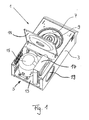
- the centrifuge 1 is designed as a laboratory centrifuge 1 in the usual way with a housing 3, with a cover not shown for a compressor cooling circuit 5, and a centrifuge container 7, with a centrifuge rotor 9 driven by a centrifuge motor (not shown), wherein the centrifuge container 7 can be closed by a centrifuge lid 11.
- Part of the centrifuge housing 3 is a base plate 13, on which the compressor 15 of the compressor cooling circuit 5 is mounted.
- an external heat exchanger 17 is provided, which is designed as a gas cooler and is cooled by a fan 19.
- the compressor cooling circuit 5 used in accordance with the invention is shown in FIG Fig. 2 shown in more detail. It can be seen that the compressor cooling circuit 5 has a coolant line 21 for CO 2 (R-744), the compressor 15 downstream with the gas cooler 17, a filter drier 23, a safety valve 25 as a safety device, an injection system 27 and an evaporator 29 in fluid communication connects.
- the evaporator 29 is a copper pipe with 10 mm inner diameter with a wall thickness of 1 mm, which was wound and impressed 14 times around the centrifuge container 7 and has a length of 18.9 m.
- the compressor 15 is a reciprocating compressor.
- the filter drier 23 is for example a steel filter, but it could also be a copper filter can be used.
- the gas cooler 17 has copper tube material with 5 mm outer diameter at 0.5 mm wall thickness, the fan 19 from the commercially available laboratory centrifuge Eppendorf 5810R was used. This laboratory centrifuge was thus adjusted overall only with regard to the compressor cooling circuit. All components are designed so that they can withstand a pressure of 172 bar.
- the internal heat exchanger 35 has an outer jacket tube 35a made of copper having an inner diameter of 10 mm and a wall thickness of 1 mm, through which the low-pressure side first portion 31 is guided, and an inner tube 35b made of copper extending in the outer jacket tube 35a , which has an inner diameter of 6 mm and a wall thickness of 1 mm, through which the high-pressure side second portion 33 is guided.
- the length of the internal heat exchanger 35 is 1.5 m.
- the refrigerant is further heated before it enters the compressor 15 and the heat that is absorbed before the compressor 15 is withdrawn from the gas cooler 17 before the refrigerant flows into the injection system 27.
- This is associated with an improvement in the efficiency.
- this also a return of liquid refrigerant in the compressor 15, which can lead to so-called "liquid shocks" avoided.
- the injection system 27 has two capillaries 37, 39, wherein the second capillary 39 can be shut off or opened by means of a solenoid valve 41.
- the first capillary 37 is 2.2 m long and has an inner diameter of 0.6 mm with a wall thickness of 0.7 mm, while the second capillary 39 has a length of 1 m and an inner diameter of 0.8 mm.
- the wall thickness is 0.6 mm.
- Both capillaries 37, 39 are formed as copper tubes, as well as the remaining parts of the piping of the coolant line 21st
- the expansion tank or the refrigerant collector has an internal volume of 0.5 l, which is connected to the coolant line 21 with a suction pipe made of copper with an outer diameter of 6 mm and an inner diameter of 4 mm.
- temperature sensors 47, 49, 51, 53 are provided which determine the compressor temperature (47), the injection temperature (49), the evaporator temperature (51) and the temperature upstream of the compressor (53).
- a pressure sensor 55 is provided which determines the compressor pressure.
- sensors may be provided for determining ambient temperature and gas cooler temperature.
- the volume of the compressor cooling circuit 5 for the refrigerant is about 3 l, with different fillings with CO 2 are possible, namely in particular in the range of 300 to 500 g. There is a safety shutdown at a compressor pressure greater than 120 bar provided.
- the comparative tests were carried out at 10 ° C, 23 ° C (room temperature) and 30 ° C in a climate chamber of the type 3705/06 Fa. Feutron. The relative humidity was at these temperatures in each case about 45%.
- the centrifuge tests were carried out with a fixed angle rotor (FWR) and a swinging bucket rotor (ASR).
- the centrifuge running time was 60 minutes per test, whereby the time from the pre-tempering of the centrifuges in the climate chamber to the temperature stability was several hours in each case.
- the centrifuge lid 11 was always closed about 0.5 h before the test start to produce a constant outlet temperature in the centrifuge container 7.
- centrifuge rotors were each 4 ml sample (water with 10% ethanol content) arranged. As part of these comparative measurements, the sample temperature was then determined in addition to the power consumption and the temperature in the inner centrifuge lid, this being done by averaging for two tests.
- the temperatures and power consumption indicated in the tables are each related to the centrifuge running time of 60 min, where T_Probe is the sample temperature and T_Deckel is the temperature at the centrifuge lid 11.
- T_Probe is the sample temperature
- T_Deckel is the temperature at the centrifuge lid 11.
- Table 1 ⁇ / u> temperature 10 ° C 23 ° C 30 ° C refrigerant R-134a R-744 R-134a R-744 R-134a R-744 Temperature / pressure switching interval -9 ° C 86/82 bar -9 ° C 86/82 bar -9 ° C 86/82 bar T_Probe 5.5 ° C 3,3 ° C 8.5 ° C 4.8 ° C 12.5 ° C 15.3 ° C T_Deckel -0.8 ° C -3.6 ° C 2.0 ° C -1.9 ° C 5.5 ° C 8.9 ° C power consumption 1.05 kWh 1.08 kWh 1.10 kWh 1,12 kWh 1.13 kWh 1.16 kWh
- Table 1 compares each test with 360 g of refrigerant for FWR for different climatic chamber temperatures, with the rotor speed set at 12,100 revolutions per minute.
- the centrifuge according to the invention has a significantly better cooling efficiency (T_Probe, T_Deckel) at temperatures below 30 ° C. than the comparison centrifuge, the power consumption in each case only being slightly higher. For 30 ° C, however, the cooling efficiency is lowered.
- Table 2 compares tests with 360 g of refrigerant for ASR for different climatic chamber temperatures, with the rotor speed set at 4,000 rpm.
- the centrifuge according to the invention again has a significantly better cooling efficiency (T_Probe, T_Deckel) at temperatures below 30 ° C. than the comparison centrifuge, the power consumption in each case only being slightly higher. For 30 ° C, however, the cooling efficiency is lowered.
- Table 3 compares tests with 470 grams of R-134a and 460 grams of R-744 refrigerant for ASR for different climatic chamber temperatures, respectively, with the rotor speed set at 4,000 revolutions per minute.
- the centrifuge according to the invention has a significantly better cooling efficiency (T_Probe, T_Deckel) at temperatures below room temperature than the comparison centrifuge. For room temperature, the differences are no longer so clear and for 30 ° C, the cooling efficiency remains reduced.
- the power consumption was only slightly higher for the centrifuge 1 according to the invention. ⁇ u> Table 4: ⁇ / u> temperature 30 ° C refrigerant R-134a R-744 Target temperature / pressure switch interval -9 ° C 100/95 bar T_Probe 7,8 ° C 5.5 ° C T_Deckel 6.0 ° C 4.2 ° C power consumption 1.23 kWh 1.29 kWh
- Table 4 compares tests with 470 g of R-134a and 460 g of R-744 refrigerant for ASR for a climate chamber temperature of 30 ° C with the rotor speed set at 4,000 rpm. In contrast to Table 3, the pressure switching points were changed to 100 bar / 95 bar.
- centrifuge 1 now also at temperatures of 30 ° C has a significantly better cooling efficiency (T_Probe, T_Deckel), as the comparison centrifuge, the power consumption is only slightly higher than at reduced compressor pressure and compared to R-134a Consumption increase of about 5%.
- the noise level of the centrifuge 1 according to the invention is lower than for the comparison centrifuge.
- the sound pressure level for the inventive centrifuge 1 at 1 m distance using ASR at 4000 rpm was 65.3 dB
- the sound pressure level using the comparative centrifuge under the same conditions was 67.9 dB.
- Oil testing in turn compared wear by determining metal contents. It was found that there is no increased wear due to the increased compressor pressure in the centrifuge 1 according to the invention compared to an oil reference sample (Idemitsu oil of the type DAPHNE PZ68S) as a new product, since there were no higher metal contents with comparable run times of about 100 h.
- oil reference sample Idemitsu oil of the type DAPHNE PZ68S
- centrifuge 1 which has a higher efficiency in terms of cooling capacity than comparable centrifuges. This is associated with virtually no or only a slightly higher power consumption. In addition, the space of the centrifuge 1 according to the invention over comparable centrifuges is not increased.
Landscapes
- Engineering & Computer Science (AREA)
- Physics & Mathematics (AREA)
- Mechanical Engineering (AREA)
- Thermal Sciences (AREA)
- General Engineering & Computer Science (AREA)
- Chemical & Material Sciences (AREA)
- Chemical Kinetics & Catalysis (AREA)
- Centrifugal Separators (AREA)
- Structures Of Non-Positive Displacement Pumps (AREA)
Priority Applications (2)
| Application Number | Priority Date | Filing Date | Title |
|---|---|---|---|
| EP14003658.3A EP3015791A1 (fr) | 2014-10-29 | 2014-10-29 | Centrifugeuse dotée d'un circuit de refroidissement de compresseur et procédé de fonctionnement d'une centrifugeuse dotée d'un circuit de refroidissement de compresseur |
| PCT/EP2015/002150 WO2016066267A2 (fr) | 2014-10-29 | 2015-10-29 | Centrifugeuse de laboratoire équipée d'un circuit de refroidissement à compression et procédé de fonctionnement d'une centrifugeuse de laboratoire équipée d'un circuit de refroidissement à compression |
Applications Claiming Priority (1)
| Application Number | Priority Date | Filing Date | Title |
|---|---|---|---|
| EP14003658.3A EP3015791A1 (fr) | 2014-10-29 | 2014-10-29 | Centrifugeuse dotée d'un circuit de refroidissement de compresseur et procédé de fonctionnement d'une centrifugeuse dotée d'un circuit de refroidissement de compresseur |
Publications (1)
| Publication Number | Publication Date |
|---|---|
| EP3015791A1 true EP3015791A1 (fr) | 2016-05-04 |
Family
ID=51868735
Family Applications (1)
| Application Number | Title | Priority Date | Filing Date |
|---|---|---|---|
| EP14003658.3A Withdrawn EP3015791A1 (fr) | 2014-10-29 | 2014-10-29 | Centrifugeuse dotée d'un circuit de refroidissement de compresseur et procédé de fonctionnement d'une centrifugeuse dotée d'un circuit de refroidissement de compresseur |
Country Status (2)
| Country | Link |
|---|---|
| EP (1) | EP3015791A1 (fr) |
| WO (1) | WO2016066267A2 (fr) |
Cited By (6)
| Publication number | Priority date | Publication date | Assignee | Title |
|---|---|---|---|---|
| EP3479903A1 (fr) | 2017-11-06 | 2019-05-08 | Sigma Laborzentrifugen GmbH | Centrifugeuse |
| WO2019238891A1 (fr) * | 2018-06-15 | 2019-12-19 | Eppendorf Ag | Centrifugeuse thermorégulée pourvue d'une protection contre les pannes |
| US20210001352A1 (en) * | 2017-12-20 | 2021-01-07 | Eppendorf Ag | Temperature-controlled Centrifuge |
| CN114226074A (zh) * | 2021-11-30 | 2022-03-25 | 浙江大学 | 基于热源分析的超重力离心装置的温控系统和温控方法 |
| EP4160109A1 (fr) * | 2021-09-30 | 2023-04-05 | Thermo Electron LED GmbH | Système de refroidissement et appareil de laboratoire doté d'un système de refroidissement |
| DE102021126963A1 (de) | 2021-10-18 | 2023-04-20 | Thermo Electron Led Gmbh | Kühlsystem |
Citations (4)
| Publication number | Priority date | Publication date | Assignee | Title |
|---|---|---|---|---|
| EP1731857A1 (fr) * | 2004-01-21 | 2006-12-13 | Mitsubishi Denki Kabushiki Kaisha | Dispositif de diagnostic de dispositif, dispositif a cycle de congelation, procede de diagnostic de circuit de fluide, systeme de surveillance de dispositif et systeme de surveillance de cycle de congelation |
| DE102006054828A1 (de) * | 2005-11-22 | 2007-05-31 | Denso Corp., Kariya | Wärmepumpen-Warmwasserbereiter |
| US20070204635A1 (en) * | 2005-02-24 | 2007-09-06 | Mitsubishi Denki Kabushiki Kaisha | Air Conditioning Apparatus |
| DE102012002593A1 (de) * | 2012-02-13 | 2013-08-14 | Eppendorf Ag | Zentrifuge mit Kompressorkühleinrichtung und Verfahren zur Steuerung einer Kompressorkühleinrichtung einer Zentrifuge |
Family Cites Families (6)
| Publication number | Priority date | Publication date | Assignee | Title |
|---|---|---|---|---|
| US6105386A (en) * | 1997-11-06 | 2000-08-22 | Denso Corporation | Supercritical refrigerating apparatus |
| US5987903A (en) * | 1998-11-05 | 1999-11-23 | Daimlerchrysler Corporation | Method and device to detect the charge level in air conditioning systems |
| US6425253B1 (en) * | 2000-06-02 | 2002-07-30 | Daimlerchrysler Corporation | Method for detecting low-charge condition in air conditioning system and device incorporating same |
| EP2489774B1 (fr) * | 2011-02-18 | 2015-06-17 | Electrolux Home Products Corporation N.V. | Sèche-linge à pompe à chaleur |
| DE102011105878A1 (de) * | 2011-06-14 | 2012-12-20 | Eppendorf Ag | Zentrifuge mit Kompressorkühlung |
| US9765979B2 (en) * | 2013-04-05 | 2017-09-19 | Emerson Climate Technologies, Inc. | Heat-pump system with refrigerant charge diagnostics |
-
2014
- 2014-10-29 EP EP14003658.3A patent/EP3015791A1/fr not_active Withdrawn
-
2015
- 2015-10-29 WO PCT/EP2015/002150 patent/WO2016066267A2/fr active Application Filing
Patent Citations (4)
| Publication number | Priority date | Publication date | Assignee | Title |
|---|---|---|---|---|
| EP1731857A1 (fr) * | 2004-01-21 | 2006-12-13 | Mitsubishi Denki Kabushiki Kaisha | Dispositif de diagnostic de dispositif, dispositif a cycle de congelation, procede de diagnostic de circuit de fluide, systeme de surveillance de dispositif et systeme de surveillance de cycle de congelation |
| US20070204635A1 (en) * | 2005-02-24 | 2007-09-06 | Mitsubishi Denki Kabushiki Kaisha | Air Conditioning Apparatus |
| DE102006054828A1 (de) * | 2005-11-22 | 2007-05-31 | Denso Corp., Kariya | Wärmepumpen-Warmwasserbereiter |
| DE102012002593A1 (de) * | 2012-02-13 | 2013-08-14 | Eppendorf Ag | Zentrifuge mit Kompressorkühleinrichtung und Verfahren zur Steuerung einer Kompressorkühleinrichtung einer Zentrifuge |
Cited By (10)
| Publication number | Priority date | Publication date | Assignee | Title |
|---|---|---|---|---|
| EP3479903A1 (fr) | 2017-11-06 | 2019-05-08 | Sigma Laborzentrifugen GmbH | Centrifugeuse |
| US20210001352A1 (en) * | 2017-12-20 | 2021-01-07 | Eppendorf Ag | Temperature-controlled Centrifuge |
| US11577257B2 (en) * | 2017-12-20 | 2023-02-14 | Eppendorf Ag | Temperature-controlled centrifuge with protective gas release in case of rotor crash |
| WO2019238891A1 (fr) * | 2018-06-15 | 2019-12-19 | Eppendorf Ag | Centrifugeuse thermorégulée pourvue d'une protection contre les pannes |
| CN112584934A (zh) * | 2018-06-15 | 2021-03-30 | 埃佩多夫股份公司 | 具有碰撞保护的温度控制离心机 |
| JP2021527559A (ja) * | 2018-06-15 | 2021-10-14 | エッペンドルフ アクチエンゲゼルシャフトEppendorf AG | 衝突保護を備えた温度コントローラ遠心分離機 |
| EP4160109A1 (fr) * | 2021-09-30 | 2023-04-05 | Thermo Electron LED GmbH | Système de refroidissement et appareil de laboratoire doté d'un système de refroidissement |
| DE102021126963A1 (de) | 2021-10-18 | 2023-04-20 | Thermo Electron Led Gmbh | Kühlsystem |
| WO2023066808A1 (fr) * | 2021-10-18 | 2023-04-27 | Thermo Electron Led Gmbh | Système de refroidissement |
| CN114226074A (zh) * | 2021-11-30 | 2022-03-25 | 浙江大学 | 基于热源分析的超重力离心装置的温控系统和温控方法 |
Also Published As
| Publication number | Publication date |
|---|---|
| WO2016066267A2 (fr) | 2016-05-06 |
| WO2016066267A3 (fr) | 2016-06-23 |
Similar Documents
| Publication | Publication Date | Title |
|---|---|---|
| EP3015791A1 (fr) | Centrifugeuse dotée d'un circuit de refroidissement de compresseur et procédé de fonctionnement d'une centrifugeuse dotée d'un circuit de refroidissement de compresseur | |
| DE102007001878B4 (de) | Ejektorpumpen-Kühlkreisvorrichtung | |
| DE3215141C2 (fr) | ||
| EP2814617B1 (fr) | Centrifugeuse de laboratoire comportant un dispositif de refroidissement à compresseur et procédé de commande d'un dispositif de refroidissement à compresseur d'une centrifugeuse de laboratoire | |
| DE3335428C2 (de) | Vorrichtung zum Regeln der Temperatur einer Flüssigkeit | |
| DE19631914C2 (de) | Überkritisch betriebene Verdichter-Kältemaschine | |
| EP3479903B1 (fr) | Centrifugeuse | |
| DE102006029973A1 (de) | Ejektorkreislaufsystem | |
| DE102011053894A1 (de) | Kälteanlage mit Kältemittelverdampferanordnung und Verfahren zur parallelen Luft- und Batteriekontaktkühlung | |
| DE112015006774T5 (de) | Kühlgerät und Verfahren zum Betrieb des Kühlgeräts | |
| EP1771689B1 (fr) | Machine frigorifique et procede d'exploitation d'une machine frigorifique | |
| DE60108677T2 (de) | Druckverminderer und Kältekreislauf zur Verwendung derselben | |
| DE602004009634T2 (de) | Kühlvorrichtung | |
| DE3229779C2 (fr) | ||
| WO2019238891A1 (fr) | Centrifugeuse thermorégulée pourvue d'une protection contre les pannes | |
| DE69513765T2 (de) | Kälteanlage | |
| DE10308268A1 (de) | Klimaanlage | |
| EP4244548A2 (fr) | Installation de thermorégulation et procédé pour faire fonctionner une installation de thermorégulation | |
| EP3071834B1 (fr) | Circuit de refroidissement | |
| DE2754132C2 (de) | Kühlvorrichtung | |
| WO2015110634A1 (fr) | Système de réfrigération | |
| EP3816543B1 (fr) | Procédé de régulation d'un détendeur | |
| EP0593495B1 (fr) | Dispositif frigorifique | |
| EP4160109A1 (fr) | Système de refroidissement et appareil de laboratoire doté d'un système de refroidissement | |
| DE102005044029B3 (de) | Wärmepumpe |
Legal Events
| Date | Code | Title | Description |
|---|---|---|---|
| PUAI | Public reference made under article 153(3) epc to a published international application that has entered the european phase |
Free format text: ORIGINAL CODE: 0009012 |
|
| AK | Designated contracting states |
Kind code of ref document: A1 Designated state(s): AL AT BE BG CH CY CZ DE DK EE ES FI FR GB GR HR HU IE IS IT LI LT LU LV MC MK MT NL NO PL PT RO RS SE SI SK SM TR |
|
| AX | Request for extension of the european patent |
Extension state: BA ME |
|
| RBV | Designated contracting states (corrected) |
Designated state(s): AL AT BE BG CH CY CZ DE DK EE ES FI FR GB GR HR HU IE IS IT LI LT LU LV MC MK MT NL NO PL PT RO RS SE SI SK SM TR |
|
| 17P | Request for examination filed |
Effective date: 20161104 |
|
| STAA | Information on the status of an ep patent application or granted ep patent |
Free format text: STATUS: THE APPLICATION IS DEEMED TO BE WITHDRAWN |
|
| 18D | Application deemed to be withdrawn |
Effective date: 20180501 |