EP3015791A1 - Centrifuge with a compressor cooling circuit and method for operating a centrifuge with a compressor cooling circuit - Google Patents
Centrifuge with a compressor cooling circuit and method for operating a centrifuge with a compressor cooling circuit Download PDFInfo
- Publication number
- EP3015791A1 EP3015791A1 EP14003658.3A EP14003658A EP3015791A1 EP 3015791 A1 EP3015791 A1 EP 3015791A1 EP 14003658 A EP14003658 A EP 14003658A EP 3015791 A1 EP3015791 A1 EP 3015791A1
- Authority
- EP
- European Patent Office
- Prior art keywords
- centrifuge
- compressor
- refrigerant
- cooling circuit
- pressure
- Prior art date
- Legal status (The legal status is an assumption and is not a legal conclusion. Google has not performed a legal analysis and makes no representation as to the accuracy of the status listed.)
- Withdrawn
Links
Images

Classifications
-
- F—MECHANICAL ENGINEERING; LIGHTING; HEATING; WEAPONS; BLASTING
- F25—REFRIGERATION OR COOLING; COMBINED HEATING AND REFRIGERATION SYSTEMS; HEAT PUMP SYSTEMS; MANUFACTURE OR STORAGE OF ICE; LIQUEFACTION SOLIDIFICATION OF GASES
- F25B—REFRIGERATION MACHINES, PLANTS OR SYSTEMS; COMBINED HEATING AND REFRIGERATION SYSTEMS; HEAT PUMP SYSTEMS
- F25B9/00—Compression machines, plants or systems, in which the refrigerant is air or other gas of low boiling point
- F25B9/002—Compression machines, plants or systems, in which the refrigerant is air or other gas of low boiling point characterised by the refrigerant
- F25B9/008—Compression machines, plants or systems, in which the refrigerant is air or other gas of low boiling point characterised by the refrigerant the refrigerant being carbon dioxide
-
- B—PERFORMING OPERATIONS; TRANSPORTING
- B04—CENTRIFUGAL APPARATUS OR MACHINES FOR CARRYING-OUT PHYSICAL OR CHEMICAL PROCESSES
- B04B—CENTRIFUGES
- B04B15/00—Other accessories for centrifuges
- B04B15/02—Other accessories for centrifuges for cooling, heating, or heat insulating
-
- F—MECHANICAL ENGINEERING; LIGHTING; HEATING; WEAPONS; BLASTING
- F25—REFRIGERATION OR COOLING; COMBINED HEATING AND REFRIGERATION SYSTEMS; HEAT PUMP SYSTEMS; MANUFACTURE OR STORAGE OF ICE; LIQUEFACTION SOLIDIFICATION OF GASES
- F25B—REFRIGERATION MACHINES, PLANTS OR SYSTEMS; COMBINED HEATING AND REFRIGERATION SYSTEMS; HEAT PUMP SYSTEMS
- F25B41/00—Fluid-circulation arrangements
- F25B41/30—Expansion means; Dispositions thereof
- F25B41/37—Capillary tubes
-
- F—MECHANICAL ENGINEERING; LIGHTING; HEATING; WEAPONS; BLASTING
- F25—REFRIGERATION OR COOLING; COMBINED HEATING AND REFRIGERATION SYSTEMS; HEAT PUMP SYSTEMS; MANUFACTURE OR STORAGE OF ICE; LIQUEFACTION SOLIDIFICATION OF GASES
- F25B—REFRIGERATION MACHINES, PLANTS OR SYSTEMS; COMBINED HEATING AND REFRIGERATION SYSTEMS; HEAT PUMP SYSTEMS
- F25B41/00—Fluid-circulation arrangements
- F25B41/30—Expansion means; Dispositions thereof
- F25B41/385—Dispositions with two or more expansion means arranged in parallel on a refrigerant line leading to the same evaporator
-
- F—MECHANICAL ENGINEERING; LIGHTING; HEATING; WEAPONS; BLASTING
- F25—REFRIGERATION OR COOLING; COMBINED HEATING AND REFRIGERATION SYSTEMS; HEAT PUMP SYSTEMS; MANUFACTURE OR STORAGE OF ICE; LIQUEFACTION SOLIDIFICATION OF GASES
- F25B—REFRIGERATION MACHINES, PLANTS OR SYSTEMS; COMBINED HEATING AND REFRIGERATION SYSTEMS; HEAT PUMP SYSTEMS
- F25B49/00—Arrangement or mounting of control or safety devices
- F25B49/02—Arrangement or mounting of control or safety devices for compression type machines, plants or systems
-
- F—MECHANICAL ENGINEERING; LIGHTING; HEATING; WEAPONS; BLASTING
- F25—REFRIGERATION OR COOLING; COMBINED HEATING AND REFRIGERATION SYSTEMS; HEAT PUMP SYSTEMS; MANUFACTURE OR STORAGE OF ICE; LIQUEFACTION SOLIDIFICATION OF GASES
- F25B—REFRIGERATION MACHINES, PLANTS OR SYSTEMS; COMBINED HEATING AND REFRIGERATION SYSTEMS; HEAT PUMP SYSTEMS
- F25B2341/00—Details of ejectors not being used as compression device; Details of flow restrictors or expansion valves
- F25B2341/06—Details of flow restrictors or expansion valves
- F25B2341/062—Capillary expansion valves
-
- F—MECHANICAL ENGINEERING; LIGHTING; HEATING; WEAPONS; BLASTING
- F25—REFRIGERATION OR COOLING; COMBINED HEATING AND REFRIGERATION SYSTEMS; HEAT PUMP SYSTEMS; MANUFACTURE OR STORAGE OF ICE; LIQUEFACTION SOLIDIFICATION OF GASES
- F25B—REFRIGERATION MACHINES, PLANTS OR SYSTEMS; COMBINED HEATING AND REFRIGERATION SYSTEMS; HEAT PUMP SYSTEMS
- F25B2400/00—General features or devices for refrigeration machines, plants or systems, combined heating and refrigeration systems or heat-pump systems, i.e. not limited to a particular subgroup of F25B
- F25B2400/04—Refrigeration circuit bypassing means
- F25B2400/0409—Refrigeration circuit bypassing means for the evaporator
-
- F—MECHANICAL ENGINEERING; LIGHTING; HEATING; WEAPONS; BLASTING
- F25—REFRIGERATION OR COOLING; COMBINED HEATING AND REFRIGERATION SYSTEMS; HEAT PUMP SYSTEMS; MANUFACTURE OR STORAGE OF ICE; LIQUEFACTION SOLIDIFICATION OF GASES
- F25B—REFRIGERATION MACHINES, PLANTS OR SYSTEMS; COMBINED HEATING AND REFRIGERATION SYSTEMS; HEAT PUMP SYSTEMS
- F25B2400/00—General features or devices for refrigeration machines, plants or systems, combined heating and refrigeration systems or heat-pump systems, i.e. not limited to a particular subgroup of F25B
- F25B2400/04—Refrigeration circuit bypassing means
- F25B2400/0411—Refrigeration circuit bypassing means for the expansion valve or capillary tube
-
- F—MECHANICAL ENGINEERING; LIGHTING; HEATING; WEAPONS; BLASTING
- F25—REFRIGERATION OR COOLING; COMBINED HEATING AND REFRIGERATION SYSTEMS; HEAT PUMP SYSTEMS; MANUFACTURE OR STORAGE OF ICE; LIQUEFACTION SOLIDIFICATION OF GASES
- F25B—REFRIGERATION MACHINES, PLANTS OR SYSTEMS; COMBINED HEATING AND REFRIGERATION SYSTEMS; HEAT PUMP SYSTEMS
- F25B2500/00—Problems to be solved
- F25B2500/26—Problems to be solved characterised by the startup of the refrigeration cycle
-
- F—MECHANICAL ENGINEERING; LIGHTING; HEATING; WEAPONS; BLASTING
- F25—REFRIGERATION OR COOLING; COMBINED HEATING AND REFRIGERATION SYSTEMS; HEAT PUMP SYSTEMS; MANUFACTURE OR STORAGE OF ICE; LIQUEFACTION SOLIDIFICATION OF GASES
- F25B—REFRIGERATION MACHINES, PLANTS OR SYSTEMS; COMBINED HEATING AND REFRIGERATION SYSTEMS; HEAT PUMP SYSTEMS
- F25B2600/00—Control issues
- F25B2600/02—Compressor control
- F25B2600/027—Compressor control by controlling pressure
- F25B2600/0271—Compressor control by controlling pressure the discharge pressure
-
- F—MECHANICAL ENGINEERING; LIGHTING; HEATING; WEAPONS; BLASTING
- F25—REFRIGERATION OR COOLING; COMBINED HEATING AND REFRIGERATION SYSTEMS; HEAT PUMP SYSTEMS; MANUFACTURE OR STORAGE OF ICE; LIQUEFACTION SOLIDIFICATION OF GASES
- F25B—REFRIGERATION MACHINES, PLANTS OR SYSTEMS; COMBINED HEATING AND REFRIGERATION SYSTEMS; HEAT PUMP SYSTEMS
- F25B2600/00—Control issues
- F25B2600/25—Control of valves
- F25B2600/2513—Expansion valves
-
- F—MECHANICAL ENGINEERING; LIGHTING; HEATING; WEAPONS; BLASTING
- F25—REFRIGERATION OR COOLING; COMBINED HEATING AND REFRIGERATION SYSTEMS; HEAT PUMP SYSTEMS; MANUFACTURE OR STORAGE OF ICE; LIQUEFACTION SOLIDIFICATION OF GASES
- F25B—REFRIGERATION MACHINES, PLANTS OR SYSTEMS; COMBINED HEATING AND REFRIGERATION SYSTEMS; HEAT PUMP SYSTEMS
- F25B2700/00—Sensing or detecting of parameters; Sensors therefor
- F25B2700/19—Pressures
- F25B2700/193—Pressures of the compressor
-
- F—MECHANICAL ENGINEERING; LIGHTING; HEATING; WEAPONS; BLASTING
- F25—REFRIGERATION OR COOLING; COMBINED HEATING AND REFRIGERATION SYSTEMS; HEAT PUMP SYSTEMS; MANUFACTURE OR STORAGE OF ICE; LIQUEFACTION SOLIDIFICATION OF GASES
- F25B—REFRIGERATION MACHINES, PLANTS OR SYSTEMS; COMBINED HEATING AND REFRIGERATION SYSTEMS; HEAT PUMP SYSTEMS
- F25B2700/00—Sensing or detecting of parameters; Sensors therefor
- F25B2700/21—Temperatures
- F25B2700/2106—Temperatures of fresh outdoor air
-
- F—MECHANICAL ENGINEERING; LIGHTING; HEATING; WEAPONS; BLASTING
- F25—REFRIGERATION OR COOLING; COMBINED HEATING AND REFRIGERATION SYSTEMS; HEAT PUMP SYSTEMS; MANUFACTURE OR STORAGE OF ICE; LIQUEFACTION SOLIDIFICATION OF GASES
- F25B—REFRIGERATION MACHINES, PLANTS OR SYSTEMS; COMBINED HEATING AND REFRIGERATION SYSTEMS; HEAT PUMP SYSTEMS
- F25B2700/00—Sensing or detecting of parameters; Sensors therefor
- F25B2700/21—Temperatures
- F25B2700/2116—Temperatures of a condenser
-
- F—MECHANICAL ENGINEERING; LIGHTING; HEATING; WEAPONS; BLASTING
- F25—REFRIGERATION OR COOLING; COMBINED HEATING AND REFRIGERATION SYSTEMS; HEAT PUMP SYSTEMS; MANUFACTURE OR STORAGE OF ICE; LIQUEFACTION SOLIDIFICATION OF GASES
- F25B—REFRIGERATION MACHINES, PLANTS OR SYSTEMS; COMBINED HEATING AND REFRIGERATION SYSTEMS; HEAT PUMP SYSTEMS
- F25B40/00—Subcoolers, desuperheaters or superheaters
Definitions
- the present invention relates to a centrifuge with a compressor cooling circuit according to the preamble of claim 1 and a method for operating a centrifuge with a compressor cooling circuit according to the preamble of claim 10.
- Centrifuges in particular laboratory centrifuges, are used to separate the components of samples centrifuged therein by utilizing the inertia of the mass. In the process, ever higher rotational speeds are used to achieve high separation rates. However, this results in a relatively high heat, which must be dissipated again by suitable cooling methods, for example, not to adversely affect the samples to be centrifuged.
- compressor cooling circuits In order to avoid overheating or to maintain certain sample temperatures in the centrifugation, especially indirect active cooling systems are used, which have a refrigerant circuit, which tempered the centrifuge tank, wherein the active cooling takes place by means of a compressor. Such refrigerant circuits are hereinafter referred to as "compressor cooling circuits”.
- the second variant is associated with a higher energy consumption and thus higher maintenance costs.
- the object of the present invention is to provide a solution with which the abovementioned disadvantages are avoided.
- the necessary space in existing centrifuges should not be increased.
- the present object can be achieved in a surprisingly simple and cost-effective manner, if the refrigerant used is not the commonly used refrigerant 1,1,1,2-tetrafluoroethane (R-134a), but CO 2 (R-134a). 744) and / or at least one hydrocarbon is used. It can be used not only pure refrigerant, but also mixtures.
- compressor cooling circuits of centrifuges have a much higher efficiency, so that they can be operated either at lower power consumption to achieve the same cooling performance as previous compressor cooling circuits such centrifuges, or it can be achieved at the same power lower cooling temperatures and a larger heat in dominate the centrifuges.
- a positive side effect of the present invention is that the refrigerants used according to the invention R-744 and hydrocarbons such as propane (R-290), propene (R-1270), butane (R-600) and isobutane (R-600a) is not recycled because they are naturally occurring substances. Thus, no greenhouse effect is associated with the possible release of the refrigerant, since these refrigerants were taken from nature.
- hydrocarbons such as propane (R-290), propene (R-1270), butane (R-600) and isobutane (R-600a)
- the centrifuge according to the invention in particular laboratory centrifuge, with a compressor cooling circuit having an external heat exchanger, an evaporator, a compressor and a refrigerant line, a centrifuge rotor, which is driven by a centrifuge motor, and a centrifuge container, which is cooled by means of the compressor cooling circuit, so distinguished in that the refrigerant of the compressor cooling circuit comprises at least one of carbon dioxide and hydrocarbons.
- the external heat exchanger is not a condenser, but a gas cooler.
- the task of the gas cooler is to cool and partially liquefy the gas, since it is in a supercritical state, which is why the gas cooler must have a corresponding area.
- the refrigerant comprises at least one substance from the group propane, propene, butane and isobutane. These are in addition to CO 2 particularly easy and inexpensive to procure and lead to a high efficiency.
- the compressor cooling circuit has an injection system arranged upstream of the evaporator, which serves as a throttle and depressurizes the refrigerant via a pressure change, wherein an injection means, preferably as an electronic injection valve or as at least a first, preferably a parallel connected first and a second capillary tube is, is provided, wherein the second capillary tube is formed in particular switched on and off.
- an injection means preferably as an electronic injection valve or as at least a first, preferably a parallel connected first and a second capillary tube is, is provided, wherein the second capillary tube is formed in particular switched on and off.
- the first capillary tube has a length in the range of 3.0 m to 0.5 m, preferably in the range of 2.5 m to 1.9 m, in particular 1.7 m and an inner diameter in the range 0.3 mm to 1 mm, preferably in the range of 0.5 mm to 0.7 mm, in particular of 0.6 mm, and / or the second capillary tube has a length in the range of 1.5 m to 0.5 m, preferably in the range 1, 2 m to 0.8 m, in particular of 1.0 m and an inner diameter in the range 0.5 mm to 1.2 mm, preferably in the range 0.7 mm to 0.9 mm, in particular of 0.8 mm and / or the at least one capillary tube has an outer diameter in the range of 1.0 mm to 3 mm, preferably in the range of 1.5 mm to 2.5 mm, in particular 2 mm.
- This injection system is particularly well adapted to the refrigerant according to the invention, in particular to R-7
- an internal heat exchanger is arranged in the compressor cooling circuit, which allows heat transfer between two areas of the refrigerant line, preferably a first area of the refrigerant line between the evaporator and compressor and a second area of the refrigerant line between the external heat exchanger and injector , wherein in particular it is provided that the internal heat exchanger is designed as two pipe sections guided into each other.
- an inner tube having an inner diameter of 6 mm and a wall thickness of 1 mm is used on the high-pressure side
- an outer tube is used with an inner diameter of 10 mm and a wall thickness of 1 mm.
- the length of the internal heat exchanger is preferably in the range 0.5 m to 2.5 m, preferably in the range 1.0 m to 2.0 m and is in particular 1.5 m.
- the refrigerant is further heated before it enters the compressor, and on the other hand, the heat that is absorbed before the compressor, the external heat exchanger or the gas cooler removed before the refrigerant flows into the injection system. This is associated with an improvement in the efficiency. In addition, this also a return of liquid refrigerant in the compressor, which can lead to so-called "liquid shocks" avoided.
- At least one bypass for bridging the internal heat exchanger exist, preferably two bypasses for bridging the internal heat exchanger consist, wherein the first bypass in the first region and the second bypass is provided in the second region of the refrigerant line.
- the internal heat exchanger is switched off and switched on and adjustable, so that an easily achievable adaptation of the compressor cooling circuit to various working conditions is possible.
- an expansion vessel or refrigerant collector is arranged upstream of the evaporator, preferably in front of the injection system, the supply line is particularly lockable and / or that there is a bypass, the coolant to the compressor and before the external heat exchanger subtracts and the evaporator and / or that before the evaporator and after the external heat exchanger, a security institution, preferably in the form of a safety valve, is arranged.
- these elements can also be arranged at other locations in the coolant circuit, but these locations are preferred.
- the amount of refrigerant can be adapted to the needs, so for example adapted to the ambient temperature.
- bypass which is a hot gas bypass
- warm refrigerant is supplied to the evaporator, whereby ice formation, for example at the triple point of CO 2 in the evaporator can be avoided.
- a bypass controllable in terms of refrigerant flow which is regulated as a function of the temperature in the suction line of the compressor.
- the bypass is used in partial load operation.
- the compressor is down-regulated or the injection system is opened, which in turn is suitably regulated as a function of the temperature in the suction line of the compressor.
- a cooling cascade can also be used in such a way that the CO 2 -based compressor cooling circuit, for example, is cooled down by means of a further cooling circuit in order to prevent critical pressure increases in the compressor cooling circuit.
- the compressor pressure is controlled as a function of at least one of the temperatures of the external heat exchanger and the ambient temperature.
- the pressures are preferably about 50-70 bar for about 10 ° C ambient temperature, about 75-90 bar for about 23 ° C ambient temperature and about 105-130 bar for about 40 ° C ambient temperature.
- the centrifuge according to the invention is used with particular advantage.
- the injection system When operating the centrifuge injection system at a higher throughput upon reaching a first compressor pressure, the injection system operates at a lower flow rate when decreasing to a second compressor pressure that is less than the first compressor pressure and the injection system again when the first compressor pressure is reached In turn, at the higher throughput is operated, then safety-related pressure increases can be avoided and it is the efficiency of the compressor cooling circuit increases.
- pressure switch points of 86 bar for the first compressor pressure and 82 bar for the second compressor pressure and in a second variant pressure switch points of 105 bar for the first compressor pressure and 100 bar for the second compressor pressure are preferred.
- the injection system for example in the form of an electronic injection valve or in the form of two capillary tubes, is operated at a higher throughput at the start of the centrifuge in order to achieve rapid cooling, but also to high pressure to avoid.
- a good evaporator utilization is achieved and the evaporator itself cooled quickly. Only later should the throughput in favor of a low evaporation temperature, and thus also the sample temperature to be achieved, be reduced, also because then essentially no longer the heat of the evaporator, but above all the heat introduced by the rotor has to be dissipated.
- the timing of the reduction in throughput is determined by monitoring the temperature at the compressor inlet, on the one hand such a decrease in the temperature is prevented that liquid hammer in the evaporator due to incomplete evaporation of the refrigerant are to be feared. On the other hand, it is monitored by means of a tendency control whether the temperature no longer appreciably decreases due to an excessive pressure on the low pressure side. In both cases, the throughput is then reduced.
- the injection system is operated at the start of the centrifuge at a higher throughput, which is lowered later to avoid liquid hammer in the evaporator and / or a persistence at too high a refrigerant temperature.
- the length of at least one capillary tube of the injection system is expedient to adapt the length of at least one capillary tube of the injection system as a function of the injection temperature and / or the refrigerant quantity and / or the compressor pressure, which also avoids safety-relevant pressure increases and the efficiency of the compressor cooling circuit can be increased.
- the length of the capillary tube should be adjusted so that it is adjusted depending on the size of the system to the respective to be reached evaporation temperature.
- the capillary tube connected in parallel can be chosen (almost) as desired, since, depending on the size, the control will then switch it on more or less often.
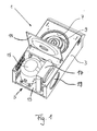
- the centrifuge 1 is designed as a laboratory centrifuge 1 in the usual way with a housing 3, with a cover not shown for a compressor cooling circuit 5, and a centrifuge container 7, with a centrifuge rotor 9 driven by a centrifuge motor (not shown), wherein the centrifuge container 7 can be closed by a centrifuge lid 11.
- Part of the centrifuge housing 3 is a base plate 13, on which the compressor 15 of the compressor cooling circuit 5 is mounted.
- an external heat exchanger 17 is provided, which is designed as a gas cooler and is cooled by a fan 19.
- the compressor cooling circuit 5 used in accordance with the invention is shown in FIG Fig. 2 shown in more detail. It can be seen that the compressor cooling circuit 5 has a coolant line 21 for CO 2 (R-744), the compressor 15 downstream with the gas cooler 17, a filter drier 23, a safety valve 25 as a safety device, an injection system 27 and an evaporator 29 in fluid communication connects.
- the evaporator 29 is a copper pipe with 10 mm inner diameter with a wall thickness of 1 mm, which was wound and impressed 14 times around the centrifuge container 7 and has a length of 18.9 m.
- the compressor 15 is a reciprocating compressor.
- the filter drier 23 is for example a steel filter, but it could also be a copper filter can be used.
- the gas cooler 17 has copper tube material with 5 mm outer diameter at 0.5 mm wall thickness, the fan 19 from the commercially available laboratory centrifuge Eppendorf 5810R was used. This laboratory centrifuge was thus adjusted overall only with regard to the compressor cooling circuit. All components are designed so that they can withstand a pressure of 172 bar.
- the internal heat exchanger 35 has an outer jacket tube 35a made of copper having an inner diameter of 10 mm and a wall thickness of 1 mm, through which the low-pressure side first portion 31 is guided, and an inner tube 35b made of copper extending in the outer jacket tube 35a , which has an inner diameter of 6 mm and a wall thickness of 1 mm, through which the high-pressure side second portion 33 is guided.
- the length of the internal heat exchanger 35 is 1.5 m.
- the refrigerant is further heated before it enters the compressor 15 and the heat that is absorbed before the compressor 15 is withdrawn from the gas cooler 17 before the refrigerant flows into the injection system 27.
- This is associated with an improvement in the efficiency.
- this also a return of liquid refrigerant in the compressor 15, which can lead to so-called "liquid shocks" avoided.
- the injection system 27 has two capillaries 37, 39, wherein the second capillary 39 can be shut off or opened by means of a solenoid valve 41.
- the first capillary 37 is 2.2 m long and has an inner diameter of 0.6 mm with a wall thickness of 0.7 mm, while the second capillary 39 has a length of 1 m and an inner diameter of 0.8 mm.
- the wall thickness is 0.6 mm.
- Both capillaries 37, 39 are formed as copper tubes, as well as the remaining parts of the piping of the coolant line 21st
- the expansion tank or the refrigerant collector has an internal volume of 0.5 l, which is connected to the coolant line 21 with a suction pipe made of copper with an outer diameter of 6 mm and an inner diameter of 4 mm.
- temperature sensors 47, 49, 51, 53 are provided which determine the compressor temperature (47), the injection temperature (49), the evaporator temperature (51) and the temperature upstream of the compressor (53).
- a pressure sensor 55 is provided which determines the compressor pressure.
- sensors may be provided for determining ambient temperature and gas cooler temperature.
- the volume of the compressor cooling circuit 5 for the refrigerant is about 3 l, with different fillings with CO 2 are possible, namely in particular in the range of 300 to 500 g. There is a safety shutdown at a compressor pressure greater than 120 bar provided.
- the comparative tests were carried out at 10 ° C, 23 ° C (room temperature) and 30 ° C in a climate chamber of the type 3705/06 Fa. Feutron. The relative humidity was at these temperatures in each case about 45%.
- the centrifuge tests were carried out with a fixed angle rotor (FWR) and a swinging bucket rotor (ASR).
- the centrifuge running time was 60 minutes per test, whereby the time from the pre-tempering of the centrifuges in the climate chamber to the temperature stability was several hours in each case.
- the centrifuge lid 11 was always closed about 0.5 h before the test start to produce a constant outlet temperature in the centrifuge container 7.
- centrifuge rotors were each 4 ml sample (water with 10% ethanol content) arranged. As part of these comparative measurements, the sample temperature was then determined in addition to the power consumption and the temperature in the inner centrifuge lid, this being done by averaging for two tests.
- the temperatures and power consumption indicated in the tables are each related to the centrifuge running time of 60 min, where T_Probe is the sample temperature and T_Deckel is the temperature at the centrifuge lid 11.
- T_Probe is the sample temperature
- T_Deckel is the temperature at the centrifuge lid 11.
- Table 1 ⁇ / u> temperature 10 ° C 23 ° C 30 ° C refrigerant R-134a R-744 R-134a R-744 R-134a R-744 Temperature / pressure switching interval -9 ° C 86/82 bar -9 ° C 86/82 bar -9 ° C 86/82 bar T_Probe 5.5 ° C 3,3 ° C 8.5 ° C 4.8 ° C 12.5 ° C 15.3 ° C T_Deckel -0.8 ° C -3.6 ° C 2.0 ° C -1.9 ° C 5.5 ° C 8.9 ° C power consumption 1.05 kWh 1.08 kWh 1.10 kWh 1,12 kWh 1.13 kWh 1.16 kWh
- Table 1 compares each test with 360 g of refrigerant for FWR for different climatic chamber temperatures, with the rotor speed set at 12,100 revolutions per minute.
- the centrifuge according to the invention has a significantly better cooling efficiency (T_Probe, T_Deckel) at temperatures below 30 ° C. than the comparison centrifuge, the power consumption in each case only being slightly higher. For 30 ° C, however, the cooling efficiency is lowered.
- Table 2 compares tests with 360 g of refrigerant for ASR for different climatic chamber temperatures, with the rotor speed set at 4,000 rpm.
- the centrifuge according to the invention again has a significantly better cooling efficiency (T_Probe, T_Deckel) at temperatures below 30 ° C. than the comparison centrifuge, the power consumption in each case only being slightly higher. For 30 ° C, however, the cooling efficiency is lowered.
- Table 3 compares tests with 470 grams of R-134a and 460 grams of R-744 refrigerant for ASR for different climatic chamber temperatures, respectively, with the rotor speed set at 4,000 revolutions per minute.
- the centrifuge according to the invention has a significantly better cooling efficiency (T_Probe, T_Deckel) at temperatures below room temperature than the comparison centrifuge. For room temperature, the differences are no longer so clear and for 30 ° C, the cooling efficiency remains reduced.
- the power consumption was only slightly higher for the centrifuge 1 according to the invention. ⁇ u> Table 4: ⁇ / u> temperature 30 ° C refrigerant R-134a R-744 Target temperature / pressure switch interval -9 ° C 100/95 bar T_Probe 7,8 ° C 5.5 ° C T_Deckel 6.0 ° C 4.2 ° C power consumption 1.23 kWh 1.29 kWh
- Table 4 compares tests with 470 g of R-134a and 460 g of R-744 refrigerant for ASR for a climate chamber temperature of 30 ° C with the rotor speed set at 4,000 rpm. In contrast to Table 3, the pressure switching points were changed to 100 bar / 95 bar.
- centrifuge 1 now also at temperatures of 30 ° C has a significantly better cooling efficiency (T_Probe, T_Deckel), as the comparison centrifuge, the power consumption is only slightly higher than at reduced compressor pressure and compared to R-134a Consumption increase of about 5%.
- the noise level of the centrifuge 1 according to the invention is lower than for the comparison centrifuge.
- the sound pressure level for the inventive centrifuge 1 at 1 m distance using ASR at 4000 rpm was 65.3 dB
- the sound pressure level using the comparative centrifuge under the same conditions was 67.9 dB.
- Oil testing in turn compared wear by determining metal contents. It was found that there is no increased wear due to the increased compressor pressure in the centrifuge 1 according to the invention compared to an oil reference sample (Idemitsu oil of the type DAPHNE PZ68S) as a new product, since there were no higher metal contents with comparable run times of about 100 h.
- oil reference sample Idemitsu oil of the type DAPHNE PZ68S
- centrifuge 1 which has a higher efficiency in terms of cooling capacity than comparable centrifuges. This is associated with virtually no or only a slightly higher power consumption. In addition, the space of the centrifuge 1 according to the invention over comparable centrifuges is not increased.
Landscapes
- Engineering & Computer Science (AREA)
- Physics & Mathematics (AREA)
- Mechanical Engineering (AREA)
- Thermal Sciences (AREA)
- General Engineering & Computer Science (AREA)
- Chemical & Material Sciences (AREA)
- Chemical Kinetics & Catalysis (AREA)
- Centrifugal Separators (AREA)
- Structures Of Non-Positive Displacement Pumps (AREA)
Abstract
Die vorliegende Erfindung betrifft eine Zentrifuge mit einem Kompressorkühlkreislauf (5) und ein Verfahren zum Betrieb einer Zentrifuge mit einem Kompressorkühlkreislauf (5). Die erfindungsgemäße Zentrifuge weist hinsichtlich der Kühlleistung einen höheren Wirkungsgrad auf als vergleichbare Zentrifugen. Dies ist mit nahezu keiner bzw. einer nur unwesentlich höheren Leistungsaufnahme verbunden. Außerdem ist der Bauraum der erfindungsgemäßen Zentrifuge gegenüber vergleichbaren Zentrifugen nicht vergrößert.The present invention relates to a centrifuge with a compressor cooling circuit (5) and a method for operating a centrifuge with a compressor cooling circuit (5). The centrifuge according to the invention has a higher efficiency in terms of cooling capacity than comparable centrifuges. This is associated with virtually no or only a slightly higher power consumption. In addition, the space of the centrifuge according to the invention over comparable centrifuges is not increased.
Description
Die vorliegende Erfindung betrifft eine Zentrifuge mit einem Kompressorkühlkreislauf nach dem Oberbegriff von Anspruch 1 und ein Verfahren zum Betrieb einer Zentrifuge mit einem Kompressorkühlkreislauf nach dem Oberbegriff von Anspruch 10.The present invention relates to a centrifuge with a compressor cooling circuit according to the preamble of
Zentrifugen, insbesondere Laborzentrifugen, werden dazu eingesetzt, um die Bestandteile von darin zentrifugierten Proben unter Ausnutzung der Massenträgheit zu trennen. Dabei werden zur Erzielung hoher Entmischungsraten immer höhere Rotationsgeschwindigkeiten eingesetzt. Dabei entsteht allerdings eine relativ hohes Wärmeaufkommen, das durch geeignete Kühlmethoden wieder abgeführt werden muss, um beispielsweise die zu zentrifugierenden Proben nicht nachteilig zu beeinflussen.Centrifuges, in particular laboratory centrifuges, are used to separate the components of samples centrifuged therein by utilizing the inertia of the mass. In the process, ever higher rotational speeds are used to achieve high separation rates. However, this results in a relatively high heat, which must be dissipated again by suitable cooling methods, for example, not to adversely affect the samples to be centrifuged.
Zur Vermeidung einer Überhitzung oder zur Einhaltung bestimmter Probentemperaturen bei der Zentrifugation werden vor allem indirekte aktive Kühlungssysteme eingesetzt, die einen Kältemittelkreislauf besitzen, der den Zentrifugenkessel temperiert, wobei die aktive Kühlung mittels eines Verdichters erfolgt. Solche Kältemittelkreisläufe werden im Folgenden "Kompressorkühlkreisläufe" genannt.In order to avoid overheating or to maintain certain sample temperatures in the centrifugation, especially indirect active cooling systems are used, which have a refrigerant circuit, which tempered the centrifuge tank, wherein the active cooling takes place by means of a compressor. Such refrigerant circuits are hereinafter referred to as "compressor cooling circuits".
Durch das beschriebene erhöhte Wärmeaufkommen ist es erforderlich, bestehende Kompressorkühlkreisläufe größer zu dimensionieren oder mit einer höheren Leistung zu betreiben. Während die erste Variante einen größeren Bauraum der Zentrifuge erforderlich macht, der sich nachteilig auf den Formfaktor auswirkt, ist die zweite Variante mit einem höheren Energieaufwand und damit höheren Unterhaltungskosten verbunden.Due to the described increased heat, it is necessary to size existing compressor cooling circuits larger or operate at a higher power. While the first variant requires a larger space of the centrifuge, which adversely affects the form factor, the second variant is associated with a higher energy consumption and thus higher maintenance costs.
Die Aufgabe der vorliegenden Erfindung besteht darin, eine Lösung bereitzustellen, mit der die oben genannten Nachteile vermieden werden. Insbesondere soll der Wirkungsgrad des Kompressorkühlkreislaufs einer Zentrifuge erhöht werden. Vorzugsweise soll dabei der notwendige Bauraum in bestehenden Zentrifugen nicht vergrößert werden.The object of the present invention is to provide a solution with which the abovementioned disadvantages are avoided. In particular, the should Increased efficiency of the compressor cooling circuit of a centrifuge. Preferably, the necessary space in existing centrifuges should not be increased.
Diese Aufgabe wird gelöst durch die erfindungsgemäße Zentrifuge nach Anspruch 1 und das erfindungsgemäße Verfahren nach Anspruch 10. Vorteilhafte Weiterbildungen sind in den abhängigen Unteransprüchen angegeben.This object is achieved by the centrifuge according to the invention according to
Der Erfinder hat erkannt, dass die vorliegende Aufgabe dadurch in überraschender Weise besonders einfach und kostengünstig gelöst werden kann, wenn als Kältemittel nicht das üblicherweise verwendete Kältemittel 1,1,1,2-Tetrafluorethan (R-134a), sondern CO2 (R-744) und/oder zumindest ein Kohlenwasserstoff eingesetzt wird. Es können dabei nicht nur reine Kältemittel, sondern auch Mischungen eingesetzt werden.The inventor has recognized that the present object can be achieved in a surprisingly simple and cost-effective manner, if the refrigerant used is not the commonly used
Damit weisen Kompressorkühlkreisläufe von Zentrifugen einen wesentlich höheren Wirkungsgrad auf, so dass sie entweder bei geringeren Leistungsaufnahmen betrieben werden können, um die gleiche Kühlleistung zu erzielen wie bisherige Kompressorkühlkreisläufe solcher Zentrifugen, oder es lassen sich bei gleicher Leistungsaufnahme tiefere Kühltemperaturen erzielen bzw. ein größeres Wärmeaufkommen in den Zentrifugen beherrschen.Thus, compressor cooling circuits of centrifuges have a much higher efficiency, so that they can be operated either at lower power consumption to achieve the same cooling performance as previous compressor cooling circuits such centrifuges, or it can be achieved at the same power lower cooling temperatures and a larger heat in dominate the centrifuges.
Die Verwendung solcher Kühlkreisläufe bei Zentrifugen war bisher nicht bekannt. Zwar waren beispielsweise Kompressorkühlkreisläufe mit R-744 schon für Großkühlanlagen, beispielsweise bei Kühlhäusern, bekannt, diese weisen jedoch sehr hohe Kühlleistungen von 10 kW und mehr auf, wobei Zentrifugen nur Kühlleistungen von ca. 1,5 kW erfordern, so dass solche Kompressorkühlkreisläufe für Zentrifugen nicht einsetzbar sind. Außerdem waren ihre Baugrößen für Zentrifugen viel zu groß.The use of such cooling circuits in centrifuges was previously unknown. Although compressor cooling circuits with R-744 were already known for large cooling systems, for example in cold stores, but these have very high cooling capacities of 10 kW and more, centrifuges only require cooling capacities of about 1.5 kW, so that such compressor cooling circuits for centrifuges can not be used. In addition, their sizes were far too large for centrifuges.
Der bessere Wirkungsgrad ergibt sich dadurch, dass bei R-134a ein Druckunterschied zwischen Niederdruck- und Hochdruckseite von 1 bar zu 8 bar, also 1:8 besteht, während beispielsweise bei R-744 ein Druckunterschied von 20 bar zu 80 bar, also von 1:4 besteht, so dass weniger Antriebsleistung zum Betrieb eines solchen R-744-Kompressorkühlkreislaufs erforderlich ist, wobei aber der absolute Druck auch wesentlich höher ist und beherrscht werden muss.The better efficiency results from the fact that in R-134a, a pressure difference between low pressure and high pressure side of 1 bar to 8 bar, ie 1: 8 while, for example, in R-744 there is a pressure differential of 20 bar to 80 bar, that is 1: 4, so that less drive power is required to operate such an R-744 compressor refrigeration cycle, but the absolute pressure is also significantly higher must be mastered.
Ein positiver Nebeneffekt der vorliegenden Erfindung ist es, dass die erfindungsgemäß verwendeten Kältemittel R-744 und Kohlenwasserstoffe, wie Propan (R-290), Propen (R-1270), Butan (R-600) und Isobutan (R-600a) nicht recycelt werden müssen, da sie natürlich vorkommende Stoffe sind. Damit ist weiterhin auch kein Treibhauseffekt bei der möglichen Freisetzung der Kältemittel verbunden, da diese Kältemittel der Natur entnommen wurden.A positive side effect of the present invention is that the refrigerants used according to the invention R-744 and hydrocarbons such as propane (R-290), propene (R-1270), butane (R-600) and isobutane (R-600a) is not recycled because they are naturally occurring substances. Thus, no greenhouse effect is associated with the possible release of the refrigerant, since these refrigerants were taken from nature.
Die erfindungsgemäße Zentrifuge, insbesondere Laborzentrifuge, mit einem Kompressorkühlkreislauf, der einen externen Wärmeübertrager, einen Verdampfer, einen Verdichter und eine Kältemitteleitung aufweist, einem Zentrifugenrotor, der von einem Zentrifugenmotor angetrieben wird, und einem Zentrifugenbehälter, der mittels des Kompressorkühlkreislaufs gekühlt wird, zeichnet sich also dadurch aus, dass das Kältemittel des Kompressorkühlkreislaufs zumindest einen Stoff aus der Gruppe Kohlendioxid und Kohlenwasserstoffe umfasst.The centrifuge according to the invention, in particular laboratory centrifuge, with a compressor cooling circuit having an external heat exchanger, an evaporator, a compressor and a refrigerant line, a centrifuge rotor, which is driven by a centrifuge motor, and a centrifuge container, which is cooled by means of the compressor cooling circuit, so distinguished in that the refrigerant of the compressor cooling circuit comprises at least one of carbon dioxide and hydrocarbons.
Im Fall im überkritischen Betrieb verwendeter Kältemittel, wie R-744, ist der externe Wärmeübertrager kein Kondensator bzw. Verflüssiger, sondern ein Gaskühler. Der Gaskühler hat die Aufgabe, das Gas zu kühlen und teilweise zu verflüssigen, da es sich in einem überkritischen Zustand befindet, weshalb der Gaskühler eine entsprechende Fläche aufweisen muss.In the case of supercritical refrigerants, such as R-744, the external heat exchanger is not a condenser, but a gas cooler. The task of the gas cooler is to cool and partially liquefy the gas, since it is in a supercritical state, which is why the gas cooler must have a corresponding area.
In einer bevorzugten Weiterbildung ist vorgesehen, dass das Kältemittel zumindest einen Stoff aus der Gruppe Propan, Propen, Butan und Isobutan umfasst. Diese sind neben CO2 besonders einfach und kostengünstig zu beschaffen und führen zu einem hohen Wirkungsgrad.In a preferred embodiment it is provided that the refrigerant comprises at least one substance from the group propane, propene, butane and isobutane. These are in addition to CO 2 particularly easy and inexpensive to procure and lead to a high efficiency.
Besonders bevorzugt weist der Kompressorkühlkreislauf ein vor dem Verdampfer angeordnetes Einspritzsystem auf, das als Drossel dient und über eine Druckänderung das Kältemittel entspannt, wobei ein Einspritzmittel, das vorzugsweise als elektronisches Einspritzventil oder als zumindest ein erstes, bevorzugt ein parallel geschaltetes erstes und ein zweites Kapillarrohr ausgebildet ist, vorgesehen ist, wobei das zweite Kapillarrohr insbesondere zu- und abschaltbar ausgebildet ist. Dadurch wird eine Steuerung der Einspritzung ermöglicht, die vor allem dazu dient, den Druck im Verdichter zu begrenzen, wie später erläutert wird.Particularly preferably, the compressor cooling circuit has an injection system arranged upstream of the evaporator, which serves as a throttle and depressurizes the refrigerant via a pressure change, wherein an injection means, preferably as an electronic injection valve or as at least a first, preferably a parallel connected first and a second capillary tube is, is provided, wherein the second capillary tube is formed in particular switched on and off. This allows control of the injection, which serves primarily to limit the pressure in the compressor, as will be explained later.
Diesbezüglich ist es vorteilhaft, wenn das erste Kapillarrohr eine Länge im Bereich 3,0 m bis 0,5 m, bevorzugt im Bereich 2,5 m bis 1,9 m, insbesondere von 1,7 m und einen Innendurchmesser im Bereich 0,3 mm bis 1 mm, bevorzugt im Bereich 0,5 mm bis 0,7 mm, insbesondere von 0,6 mm aufweist und/oder das zweite Kapillarrohr eine Länge im Bereich 1,5 m bis 0,5 m, bevorzugt im Bereich 1,2 m bis 0,8 m, insbesondere von 1,0 m und einen Innendurchmesser im Bereich 0,5 mm bis 1,2 mm, bevorzugt im Bereich 0,7 mm bis 0,9 mm, insbesondere von 0,8 mm aufweist und/oder das zumindest ein Kapillarrohr einen Außendurchmesser im Bereich 1,0 mm bis 3 mm, bevorzugt im Bereich 1,5 mm bis 2,5 mm, insbesondere 2 mm aufweist. Dieses Einspritzsystem ist besonders gut an die erfindungsgemäßen Kältemittel, insbesondere an R-744 im Zusammenhang mit den erforderlichen Auslegungen von Zentrifugen angepasst.In this regard, it is advantageous if the first capillary tube has a length in the range of 3.0 m to 0.5 m, preferably in the range of 2.5 m to 1.9 m, in particular 1.7 m and an inner diameter in the range 0.3 mm to 1 mm, preferably in the range of 0.5 mm to 0.7 mm, in particular of 0.6 mm, and / or the second capillary tube has a length in the range of 1.5 m to 0.5 m, preferably in the
In einer besonders bevorzugten Weiterbildung ist vorgesehen, dass ein interner Wärmeübertrager im Kompressorkühlkreislauf angeordnet ist, der eine Wärmeübertragung zwischen zwei Bereichen der Kältemittelleitung gestattet, wobei bevorzugt ein erster Bereich der Kältemittelleitung zwischen Verdampfer und Verdichter und ein zweiter Bereich der Kältemittelleitung zwischen externem Wärmeübertrager und Einspritzorgan liegt, wobei insbesondere vorgesehen ist, dass der interne Wärmeübertrager als zwei ineinander geführte Rohrabschnitte ausgebildet ist. Beispielsweise wird hochdruckseitig ein inneres Rohr verwendet, das einen Innendurchmesser von 6 mm und eine Wandstärke von 1 mm aufweist, während niederdruckseitig ein äußeres Rohr verwendet wird mit einem Innendurchmesser von 10 mm und einer Wandstärke von 1 mm. Die Länge des internen Wärmeübertragers liegt vorzugsweise im Bereich 0,5 m bis 2,5 m, bevorzugt im Bereich 1,0 m bis 2,0 m und beträgt insbesondere 1,5 m.In a particularly preferred embodiment, it is provided that an internal heat exchanger is arranged in the compressor cooling circuit, which allows heat transfer between two areas of the refrigerant line, preferably a first area of the refrigerant line between the evaporator and compressor and a second area of the refrigerant line between the external heat exchanger and injector , wherein in particular it is provided that the internal heat exchanger is designed as two pipe sections guided into each other. For example, an inner tube having an inner diameter of 6 mm and a wall thickness of 1 mm is used on the high-pressure side On the low pressure side, an outer tube is used with an inner diameter of 10 mm and a wall thickness of 1 mm. The length of the internal heat exchanger is preferably in the range 0.5 m to 2.5 m, preferably in the range 1.0 m to 2.0 m and is in particular 1.5 m.
Damit sind mehrere vorteilhafte Wirkungen verbunden. Zum einen wird das Kältemittel weiter erhitzt bevor es in den Verdichter gelangt und zum anderen wird die Wärme, die vor dem Verdichter aufgenommen wird, dem externen Wärmeübertrager bzw. dem Gaskühler entzogen bevor das Kältemittel in das Einspritzsystem fließt. Damit ist eine Verbesserung des Wirkungsgrades verbunden. Außerdem wird dadurch auch eine Rückführung von flüssigem Kältemittel in den Verdichter, die zu sogenannten "Flüssigkeitsschlägen" führen kann, vermieden.This is associated with several beneficial effects. On the one hand, the refrigerant is further heated before it enters the compressor, and on the other hand, the heat that is absorbed before the compressor, the external heat exchanger or the gas cooler removed before the refrigerant flows into the injection system. This is associated with an improvement in the efficiency. In addition, this also a return of liquid refrigerant in the compressor, which can lead to so-called "liquid shocks" avoided.
In diesem Zusammenhang kann vorteilhaft zumindest ein Bypass zur Überbrückung des internen Wärmeübertragers bestehen, bevorzugt können zwei Bypässe zur Überbrückung des internen Wärmeübertragers bestehen, wobei der erste Bypass im ersten Bereich und der zweite Bypass im zweiten Bereich der Kältemittelleitung vorgesehen ist. Dadurch ist der interne Wärmeübertrager ab- und zuschaltbar und regelbar ausgelegt, so dass eine leicht erzielbare Anpassung des Kompressorkühlkreislaufs an verschiedene Arbeitsbedingungen möglich ist.In this context, advantageously at least one bypass for bridging the internal heat exchanger exist, preferably two bypasses for bridging the internal heat exchanger consist, wherein the first bypass in the first region and the second bypass is provided in the second region of the refrigerant line. As a result, the internal heat exchanger is switched off and switched on and adjustable, so that an easily achievable adaptation of the compressor cooling circuit to various working conditions is possible.
Für diese Ausgestaltung eines Wärmeübertragers wird selbständiger Schutz beansprucht, also unabhängig davon, ob dieser in Zentrifugen bzw. Kompressorkühlkreisläufen in Zentrifugen eingesetzt wird.For this embodiment of a heat exchanger independent protection is claimed, that is, regardless of whether this is used in centrifuges or Kompressorkühlkreisläufe in centrifuges.
Weitere bevorzugte Ausgestaltungen bestehen darin, dass vor dem Verdampfer, bevorzugt vor dem Einspritzsystem, ein Ausdehnungsgefäß bzw. Kältemittelsammler angeordnet ist, dessen Zuleitung insbesondere absperrbar ausgebildet ist und/oder dass ein Bypass besteht, der Kühlmittel nach dem Verdichter und vor dem externen Wärmeübertrager abzieht und dem Verdampfer zuführt und/oder dass vor dem Verdampfer und nach dem externen Wärmeübetrager ein Sicherheitsorgan, bevorzugt in Form eines Sicherheitsventils, angeordnet ist. Alternativ können diese Elemente auch an anderen Stellen im Kühlmittelkreislauf angeordnet werden, allerdings werden diese Stellen bevorzugt.Further preferred embodiments are that upstream of the evaporator, preferably in front of the injection system, an expansion vessel or refrigerant collector is arranged, the supply line is particularly lockable and / or that there is a bypass, the coolant to the compressor and before the external heat exchanger subtracts and the evaporator and / or that before the evaporator and after the external heat exchanger, a security institution, preferably in the form of a safety valve, is arranged. Alternatively, these elements can also be arranged at other locations in the coolant circuit, but these locations are preferred.
Mit dem Ausdehnungsgefäß bzw. Kältemittelsammler wie auch dem Sicherheitsventil wird sichergestellt, dass es im Stillstand der Zentrifuge und des Kompressorkühlkreislaufs nicht zu einem Bersten des Kompressorkühlkreislaufs bzw. Leckagen aufgrund sicherheitsrelevanter Druckerhöhung kommt.With the expansion vessel or refrigerant collector as well as the safety valve, it is ensured that the compressor cooling circuit or bursting due to safety-related pressure increase does not burst during standstill of the centrifuge and the compressor cooling circuit.
Außerdem kann mit dem Ausdehnungsgefäß bzw. Kältemittelsammler die Kältemittelmenge an den Bedarf angepasst werden, also beispielsweise an die Umgebungstemperatur angepasst werden.In addition, with the expansion tank or refrigerant collector, the amount of refrigerant can be adapted to the needs, so for example adapted to the ambient temperature.
Aufgrund der hohen Verdichterdrücke im Gegensatz zu R-134a muss die erfindungsgemäße Zentrifuge sicherheitstechnisch entsprechend ausgelegt sein. Alle Komponenten könnten hierzu auf einen 3-fachen Arbeitsdruck ausgelegt werden, was aber zu einer massiven Überdimensionierung führen würde. Stattdessen ist vorgesehen, dass der Arbeitsdruck, also der Verdichterdruck auf einen Bereich 100 bar bis 140 bar, bevorzugt maximal 130 bar, insbesondere maximal 120 bar beschränkt wird und bei einem Überschreiten eine Abschaltung des Verdichters erfolgt. Aufgrund von Toleranzen bei der Druckbestimmung von üblicherweise 10% ist bei einem kontrollierten Verdichterdruck von 120 bar ein realer Druck von bis zu ca. 132 bar verbunden. Aus Sicherheitsgründen wird das System dann auf eine Maximalbelastung von 120 bar x 1,43 = 171,6 bar ausgelegt.Due to the high compressor pressures in contrast to R-134a, the centrifuge according to the invention must be designed according to safety. All components could be designed for this purpose to a 3-times working pressure, but this would lead to a massive over-dimensioning. Instead, it is provided that the working pressure, ie the compressor pressure to a range of 100 bar to 140 bar, preferably a maximum of 130 bar, in particular a maximum of 120 bar is limited and takes place when exceeding a shutdown of the compressor. Due to tolerances in the pressure determination of usually 10%, a real pressure of up to about 132 bar is associated with a controlled compressor pressure of 120 bar. For safety reasons, the system is then designed for a maximum load of 120 bar x 1.43 = 171.6 bar.
Mit dem Bypass, der ein Heißgasbypass ist, wird erreicht, dass warmes Kältemittel dem Verdampfer zugeführt wird, wodurch eine Eisbildung beispielsweise am Tripelpunkt von CO2 im Verdampfer vermieden werden kann. Diesbezüglich wird vorzugsweise ein hinsichtlich des Kältemittelflusses steuerbarer Bypass verwendet, der in Abhängigkeit von der Temperatur in der Saugleitung des Verdichters geregelt wird. Zweckmäßig wird der Bypass im Teillastbetrieb eingesetzt.With the bypass, which is a hot gas bypass, it is achieved that warm refrigerant is supplied to the evaporator, whereby ice formation, for example at the triple point of CO 2 in the evaporator can be avoided. In this regard, it is preferable to use a bypass controllable in terms of refrigerant flow, which is regulated as a function of the temperature in the suction line of the compressor. Advantageously, the bypass is used in partial load operation.
Alternativ oder zusätzlich kann auch zur Verhinderung solcher Eisbildung bzw. Bereifung vorgesehen sein, dass der Verdichter heruntergeregelt wird oder das Einspritzsystem geöffnet wird, was wiederum zweckmäßig in Abhängigkeit von der Temperatur in der Saugleitung des Verdichters geregelt wird.Alternatively or additionally, to prevent such ice formation or tires may be provided that the compressor is down-regulated or the injection system is opened, which in turn is suitably regulated as a function of the temperature in the suction line of the compressor.
Zusätzlich oder alternativ kann auch eine Kühlkaskade dahingehend verwendet werden, dass der beispielsweise CO2 basierte Kompressorkühlkreislauf mittels eines weiteren Kühlkreislaufs im Stillstand gekühlt wird, um kritische Druckerhöhungen im Kompressorkühlkreislauf zu verhindern.Additionally or alternatively, a cooling cascade can also be used in such a way that the CO 2 -based compressor cooling circuit, for example, is cooled down by means of a further cooling circuit in order to prevent critical pressure increases in the compressor cooling circuit.
In einer bevorzugten Ausgestaltung sind ein oder mehrere der folgenden Mittel zum Steuern vorgesehen, wobei mit "Mitteln zum Steuern" im Rahmen der vorliegenden Erfindung auch stets Mittel zum Regeln mit offenbart sind. Durch die nachfolgend genannten Mittel kann jeweils der Wirkungsgrad verbessert und es können sicherheitsrelevante Druckerhöhungen vermieden werden.
- 1. Mittel, die Kältemittelmenge in Abhängigkeit von der Umgebungstemperatur und/oder der gewünschten Kühltemperatur und/oder des Verdichterdrucks zu steuern. Anstelle der Umgebungstemperatur kann auch die Temperatur des externen Wärmeübertragers verwendet werden.
- 2. Mittel, das Einspritzsystem in Abhängigkeit vom Druck im Kompressorkühlkreislauf zu steuern, bevorzugt das zweite Kapillarrohr bei einem bestimmten Druckschaltpunkt zuzuschalten.
- 3. Mittel, die Länge zumindest eines Kapillarrohres in Abhängigkeit von der Einspritztemperatur und/oder der Kältemittelmenge und/oder des Verdichterdrucks anzupassen. Hinsichtlich der Länge könnte beispielsweise eine Kaskade von Kapillarrohren unterschiedlicher Länge vorgesehen sein, die über entsprechende Ventile zuschaltbar sind, wobei entsprechende Bypässe abschaltbar sind, so dass beliebige Kombinationen von in Reihe geschalteten Kapillarrohrlängen ermöglicht werden.
- 4. Mittel, den Verdichterdruck in Abhängigkeit von zumindest einer der Temperaturen Temperatur des externen Wärmeübertragers und Umgebungstemperatur anzupassen.
- 1. Means to control the amount of refrigerant in dependence on the ambient temperature and / or the desired cooling temperature and / or the compressor pressure. Instead of the ambient temperature, the temperature of the external heat exchanger can also be used.
- Second means to control the injection system as a function of the pressure in the compressor cooling circuit, preferably the second capillary tube zuzuschalten at a certain pressure switching point.
- 3. Means to adapt the length of at least one capillary tube in dependence on the injection temperature and / or the refrigerant quantity and / or the compressor pressure. With regard to the length, for example, a cascade of capillary tubes of different lengths could be provided, which via corresponding valves can be switched, with corresponding bypasses are switched off, so that any combination of series capillary tube lengths are possible.
- 4. means to adjust the compressor pressure in dependence on at least one of the temperatures of the external heat exchanger and ambient temperature.
Unabhängiger Schutz wird beansprucht für das erfindungsgemäße Verfahren zum Betrieb einer Zentrifuge, insbesondere Laborzentrifuge, mit einem Kompressorkühlkreislauf, der einen externen Wärmeübertrager, einen Verdampfer, einen Verdichter und eine Kältemitteleitung aufweist, einem Zentrifugenrotor, der von einem Zentrifugenmotor angetrieben wird, und einem Zentrifugenbehälter, der mittels des Kompressorkühlkreislaufs gekühlt wird, das sich dadurch auszeichnet, dass als Kältemittel des Kompressorkühlkreislaufs zumindest ein Stoff aus der Gruppe Kohlendioxid und Kohlenwasserstoffe verwendet wird.Independent protection is claimed for the inventive method for operating a centrifuge, in particular laboratory centrifuge, with a compressor cooling circuit having an external heat exchanger, an evaporator, a compressor and a refrigerant line, a centrifuge rotor, which is driven by a centrifuge motor, and a centrifuge container, the is cooled by the compressor cooling circuit, which is characterized in that is used as the refrigerant of the compressor cooling circuit at least one substance from the group carbon dioxide and hydrocarbons.
In einer vorteilhaften Weiterbildung ist vorgesehen, die Kältemittelmenge in Abhängigkeit der Umgebungstemperatur und/oder der gewünschten Kühltemperatur und/oder des Drucks im Verdichter zu steuern. Dadurch wird der Wirkungsgrad verbessert und es können sicherheitsrelevante Druckerhöhungen vermieden werden.In an advantageous development, it is provided to control the amount of refrigerant as a function of the ambient temperature and / or the desired cooling temperature and / or the pressure in the compressor. As a result, the efficiency is improved and it can safety-related pressure increases can be avoided.
Alternativ oder zusätzlich kann vorgesehen sein, dass der Verdichterdruck in Abhängigkeit von zumindest einer der Temperaturen Temperatur des externen Wärmeübertragers und Umgebungstemperatur gesteuert wird.Alternatively or additionally, it may be provided that the compressor pressure is controlled as a function of at least one of the temperatures of the external heat exchanger and the ambient temperature.
Dabei ist festzustellen, dass die Kältemittelmenge von der Maschinengröße abhängt, wobei bei höheren Umgebungstemperaturen eine größere Füllmenge bessere Ergebnisse erzielt. Die Drücke liegen dabei bevorzugt bei ca. 50-70 bar für etwa 10°C Umgebungstemperatur, bei ca. 75-90 bar für etwa 23°C Umgebungstemperatur und bei ca. 105-130 bar für etwa 40°C Umgebungstemperatur.It should be noted that the amount of refrigerant depends on the size of the machine, and at higher ambient temperatures, a larger capacity will give better results. The pressures are preferably about 50-70 bar for about 10 ° C ambient temperature, about 75-90 bar for about 23 ° C ambient temperature and about 105-130 bar for about 40 ° C ambient temperature.
Besonders vorteilhaft wird die erfindungsgemäße Zentrifuge verwendet.The centrifuge according to the invention is used with particular advantage.
Wenn das Einspritzsystem der Zentrifuge bei Erreichen eines ersten Verdichterdrucks bei einem höheren Durchsatz betrieben wird, das Einspritzsystem bei einem Absinken auf einen zweiten Verdichterdruck, der kleiner ist als der erste Verdichterdruck, bei dem geringeren Durchsatz betrieben wird und das Einspritzsystem bei erneutem Erreichen des ersten Verdichterdrucks wiederum bei dem höheren Durchsatz betrieben wird, dann können sicherheitsrelevante Druckanstiege vermieden werden und es wird der Wirkungsgrad des Kompressorkühlkreislaufs erhöht.When operating the centrifuge injection system at a higher throughput upon reaching a first compressor pressure, the injection system operates at a lower flow rate when decreasing to a second compressor pressure that is less than the first compressor pressure and the injection system again when the first compressor pressure is reached In turn, at the higher throughput is operated, then safety-related pressure increases can be avoided and it is the efficiency of the compressor cooling circuit increases.
Vorteilhaft liegt zumindest einer der ersten und zweiten Verdichterdrücke im Bereich 75 bar bis 115 bar, bevorzugt im Bereich 80 bar bis 105 bar. Weiterhin vorteilhaft liegt der Abstand des ersten vom zweiten Verdichterdruck im Bereich 1 bar bis 10 bar, bevorzugt 2 bar bis 7 bar, insbesondere 4 bar bis 5 bar, wodurch eine Hysterese erzeugt wird, die ein dauerhaftes Hin- und Herschalten bei Erreichen des Druckschaltpunktes verhindert. Dabei werden in einer Variante Druckschaltpunkte von 86 bar für den ersten Verdichterdruck und 82 bar für den zweiten Verdichterdruck sowie in einer zweiten Variante Druckschaltpunkte von 105 bar für den ersten Verdichterdruck und 100 bar für den zweiten Verdichterdruck bevorzugt.Advantageously, at least one of the first and second compressor pressures in the range 75 bar to 115 bar, preferably in the range 80 bar to 105 bar. Further advantageously, the distance of the first from the second compressor pressure in the
Von Vorteil ist es weiterhin, wenn zunächst beim Start der Zentrifuge das Einspritzsystem, beispielsweise in Form eines elektronisches Einspritzventils oder in Form zweier Kapillarrohre, mit einem höheren Durchsatz betrieben wird, um zum eine schnelle Abkühlung zu erreichen, aber auch, um einen zu hohen Hochdruck zu vermeiden. Dadurch wird eine gute Verdampferausnutzung erreicht und der Verdampfer selbst schnell abgekühlt. Erst später sollte der Durchsatz zugunsten einer niedrigen Verdampfungstemperatur, und somit auch der zu erreichenden Probentemperatur, verringert werden, auch weil dann im Wesentlichen nicht mehr die Wärme des Verdampfers, sondern vor allem die durch den Rotor eingetragene Wärme abgeführt werden muss.It is also advantageous if initially the injection system, for example in the form of an electronic injection valve or in the form of two capillary tubes, is operated at a higher throughput at the start of the centrifuge in order to achieve rapid cooling, but also to high pressure to avoid. As a result, a good evaporator utilization is achieved and the evaporator itself cooled quickly. Only later should the throughput in favor of a low evaporation temperature, and thus also the sample temperature to be achieved, be reduced, also because then essentially no longer the heat of the evaporator, but above all the heat introduced by the rotor has to be dissipated.
Der Zeitpunkt der Reduzierung des Durchsatzes wird durch Überwachung der Temperatur am Verdichtereingang bestimmt, wobei einerseits ein solches Absinken der Temperatur verhindert wird, dass Flüssigkeitsschläge im Verdampfer aufgrund nicht vollständiger Verdampfung des Kältemittels zu befürchten sind. Andererseits wird mittels einer Tendenzkontrolle überwacht, ob sich die Temperatur aufgrund eines zu hohen Drucks auf der Niederdruckseite nicht mehr merklich verringert. In beiden Fällen wird dann der Durchsatz verringert.The timing of the reduction in throughput is determined by monitoring the temperature at the compressor inlet, on the one hand such a decrease in the temperature is prevented that liquid hammer in the evaporator due to incomplete evaporation of the refrigerant are to be feared. On the other hand, it is monitored by means of a tendency control whether the temperature no longer appreciably decreases due to an excessive pressure on the low pressure side. In both cases, the throughput is then reduced.
Es ist also vorteilhaft, wenn das Einspritzsystem beim Start der Zentrifuge bei einem höheren Durchsatz betrieben wird, der später zur Vermeidung von Flüssigkeitsschlägen im Verdampfer und/oder bei einem Verharren bei einer zu hohen Kältemitteltemperatur abgesenkt wird.It is therefore advantageous if the injection system is operated at the start of the centrifuge at a higher throughput, which is lowered later to avoid liquid hammer in the evaporator and / or a persistence at too high a refrigerant temperature.
Außerdem ist es zweckmäßig, die Länge zumindest eines Kapillarrohres des Einspritzsystems in Abhängigkeit von der Einspritztemperatur und/oder der Kältemittelmenge und/oder des Verdichterdrucks anzupassen, wodurch ebenfalls sicherheitsrelevante Druckanstiege vermieden und der Wirkungsgrad des Kompressorkühlkreislaufs erhöht werden können. Dabei sollte die Länge des Kapillarrohrs so eingestellt werden, dass sie abhängig von der Anlagengröße auf die jeweils zu erreichende Verdampfungstemperatur angepasst ist. Das dazu parallel geschaltete Kapillarrohr kann (fast) beliebig gewählt werden, da je nach Größe die Regelung dieses dann öfter oder weniger oft zuschalten wird.In addition, it is expedient to adapt the length of at least one capillary tube of the injection system as a function of the injection temperature and / or the refrigerant quantity and / or the compressor pressure, which also avoids safety-relevant pressure increases and the efficiency of the compressor cooling circuit can be increased. The length of the capillary tube should be adjusted so that it is adjusted depending on the size of the system to the respective to be reached evaporation temperature. The capillary tube connected in parallel can be chosen (almost) as desired, since, depending on the size, the control will then switch it on more or less often.
Für sämtliche Merkmale des Einspritzsystems und dessen Steuerung bzw. Regelung, insbesondere die Ausgestaltung mit zwei Kapillarrohren, wird für sich genommen selbständiger Schutz beansprucht. Dabei kann dieses Einspritzsystem auch völlig unabhängig von dem im Rahmen dieser Erfindung eingesetzten Kältemittel vorteilhaft verwendet werden, da auch für andere Kältemittel damit ein Überdruck verhindert bzw. beim Start eine optimale und beschleunigte Abkühlung erreicht wird. Die Kennzeichen und weitere Vorteile der Erfindung werden im Rahmen der folgenden Beschreibung eines bevorzugten Ausführungsbeispiels im Zusammenhang mit den Figuren deutlich werden. Dabei zeigen rein schematisch:
- Fig. 1
- die erfindungsgemäße Zentrifuge in einer perspektivischen Ansicht und
- Fig. 2
- den in der Zentrifuge nach
Fig. 1 verwendeten Kompressorkühlkreislauf in einer Fließbilddarstellung.
- Fig. 1
- the centrifuge according to the invention in a perspective view and
- Fig. 2
- in the centrifuge
Fig. 1 used compressor cooling circuit in a flow diagram.
In
Der erfindungsgemäß verwendete Kompressorkühlkreislauf 5 ist in
Der Verdichter 15 ist ein Hubkolbenkompressor. Der Filtertrockner 23 ist beispielsweise ein Stahlfilter, es könnte aber auch ein Kupferfilter verwendet werden. Der Gaskühler 17 weist Kupferrohrmaterial mit 5 mm Außendurchmesser bei 0,5 mm Wandstärke auf, wobei der Lüfter 19 aus der kommerziell erhältlichen Laborzentrifuge Eppendorf 5810R verwendet wurde. Diese Laborzentrifuge wurde also insgesamt nur hinsichtlich des Kompressorkühlkreislaufs angepasst. Dabei sind alle Bauteile so ausgelegt, dass sie einem Druck von 172 bar standhalten.The
Zwischen einem niederdruckseitigen ersten Bereich 31 der Kältemittelleitung 21, der zwischen Verdampfer 29 und Verdichter 15 verläuft, und einem hochdruckseitigen zweiten Bereich 33 der Kältemittelleitung 21, der zwischen dem Gaskühler 17 und Einspritzsystem 27 verläuft, ist ein interner Wärmeübertrager 35 angeordnet. Der interne Wärmeübertrager 35 weist ein äußeres Mantelrohr 35a aus Kupfer, das einen Innendurchmesser von 10 mm und eine Wandstärke von 1 mm besitzt, durch das der niederdruckseitige erste Bereich 31 geführt wird, und ein in dem äußeren Mantelrohr 35a verlaufendes inneres Rohr 35b aus Kupfer auf, das einen Innendurchmesser von 6 mm und eine Wandstärke von 1 mm besitzt, durch das der hochdruckseitige zweite Bereich 33 geführt wird. Die Länge des internen Wärmeübertragers 35 beträgt 1,5 m.Between a low-pressure-side
Damit wird das Kältemittel weiter erhitzt bevor es in den Verdichter 15 gelangt und die Wärme, die vor dem Verdichter 15 aufgenommen wird, wird dem Gaskühler 17 entzogen bevor das Kältemittel in das Einspritzsystem 27 fließt. Damit ist eine Verbesserung des Wirkungsgrades verbunden. Außerdem wird dadurch auch eine Rückführung von flüssigem Kältemittel in den Verdichter 15, die zu sogenannten "Flüssigkeitsschlägen" führen kann, vermieden.Thus, the refrigerant is further heated before it enters the
Das Einspritzsystem 27 weist zwei Kapillaren 37, 39 auf, wobei die zweite Kapillare 39 mittels eines Magnetventils 41 abgesperrt bzw. geöffnet werden kann. Die erste Kapillare 37 ist dabei 2,2 m lang und weist einen Innendurchmesser von 0,6 mm bei einer Wandstärke von 0,7mm auf, während die zweite Kapillare 39 eine Länge von 1 m aufweist und einen Innendurchmesser von 0,8 mm besitzt. Hierbei ist die Wandstärke 0,6 mm. Beide Kapillaren 37, 39 sind als Kupferrohre ausgebildet, wie auch der übrige Teile der Verrohrung der Kühlmitteleitung 21.The
Es ist ein Befüllventil 43 für CO2 stromaufwärts vor dem Verdichter 15 vorgesehen und ein Ablassventil 45 stromabwärts nach dem Verdichter 15, das mit einem Ausdehnungsgefäß bzw. Kältemittelsammler (nicht gezeigt) verbunden ist. Das Ausdehnungsgefäß bzw. der Kältemittelsammler weist ein Innenvolumen von 0,5 I auf, der mit einer Saugleitung aus Kupfer mit einem Außendurchmesser von 6 mm und einem Innendurchmesser von 4 mm mit der Kühlmittelleitung 21 verbunden ist.There is a
Schließlich sind Temperatursensoren 47, 49, 51, 53 vorgesehen, die die Verdichtertemperatur (47), die Einspritztemperatur (49), die Verdampfertemperatur (51) und die Temperatur vor dem Verdichter (53) bestimmen. Außerdem ist ein Drucksensor 55 vorgesehen, der den Verdichterdruck bestimmt. Zusätzlich, und nicht gezeigt, können Sensoren zur Bestimmung der Umgebungstemperatur und der Gaskühlertemperatur vorgesehen sein.Finally,
Nicht gezeigt sind auch weitere Zusatzoptionen, die in dem erfindungsgemäßen Kompressorkühlkreislauf 5 Verwendung finden könnten, nämlich ein regelbarer Bypass, der Kühlmittel nach dem Verdichter 15 und vor dem Gaskühler 17 abzieht und dem Verdampfer 29 nach dem Einspritzsystem 27 zuführt und regelbare Bypässe zur Umgehung des internen Wärmeübertragers 35 jeweils im ersten 31 und zweiten Bereich 33 der Kühlmittelleitung.Not shown are also additional options that could be used in the
Das Volumen des Kompressorkühlkreislaufs 5 für das Kältemittel beträgt ca. 3 I, wobei verschiedene Befüllungen mit CO2 möglich sind, nämlich insbesondere im Bereich von 300 bis 500 g. Es ist eine Sicherheitsabschaltung bei einem Verdichterdruck größer 120 bar vorgesehen.The volume of the
Es wurden Vergleichsuntersuchungen zwischen der erfindungsgemäßen Zentrifuge mit R-744 und der Vergleichszentrifuge Eppendorf 5810R mit R-134a für Befüllungen mit 350 g und 470g/460 g vorgenommen, die im Folgenden näher dargestellt werden.Comparative tests were carried out between the centrifuge according to the invention with R-744 and the comparison centrifuge Eppendorf 5810R with R-134a for fillings of 350 g and 470 g / 460 g, which are described in more detail below.
Die Vergleichsuntersuchungen erfolgten bei 10 °C, 23 °C (Raumtemperatur) und 30 °C in einer Klimakammer des Typs 3705/06 der Fa. Feutron. Die relative Luftfeuchte betrug bei diesen Temperaturen jeweils ca. 45%. Die Zentrifugentests erfolgten mit einem Festwinkelrotor (FWR) und einem Ausschwingrotor (ASR).The comparative tests were carried out at 10 ° C, 23 ° C (room temperature) and 30 ° C in a climate chamber of the type 3705/06 Fa. Feutron. The relative humidity was at these temperatures in each case about 45%. The centrifuge tests were carried out with a fixed angle rotor (FWR) and a swinging bucket rotor (ASR).
Die Zentrifugenlaufzeit betrug 60 min pro Test, wobei die Zeit von der Vortemperierung der Zentrifugen in der Klimakammer bis zur Temperaturkonstanz jeweils mehrere Stunden betrug. Der Zentrifugendeckel 11 wurde immer ca. 0,5 h vor dem Teststart geschlossen, um im Zentrifugenbehälter 7 eine konstante Ausgangstemperatur herzustellen.The centrifuge running time was 60 minutes per test, whereby the time from the pre-tempering of the centrifuges in the climate chamber to the temperature stability was several hours in each case. The
In den Zentrifugenrotoren waren jeweils 4 ml Probengut (Wasser mit 10% Ethanolanteil) angeordnet. Im Rahmen dieser Vergleichsmessungen wurde dann neben dem Stromverbrauch und der Temperatur im inneren Zentrifugendeckel auch die Probentemperatur ermittelt, wobei dies jeweils durch Mittelwertbildung für zwei Tests erfolgte.In the centrifuge rotors were each 4 ml sample (water with 10% ethanol content) arranged. As part of these comparative measurements, the sample temperature was then determined in addition to the power consumption and the temperature in the inner centrifuge lid, this being done by averaging for two tests.
In den nachfolgenden Tabellen 1 bis 4 sind jeweils die Ergebnisse dargestellt, wobei für die Vergleichszentrifuge Eppendorf 5810R mit R-134a eine Temperatur von -9 °C vorgegeben wurde, während für die erfindungsgemäße Zentrifuge 1 Druckschaltintervalle für den Verdichterdruck vorgegeben wurden, der jeweils über den Drucksensor 55 bestimmt wurde. Dabei gibt der erste Wert den Schaltpunkt an, bei dessen Erreichen das Magnetventil 41 das zweite Kapillarrohr 39 öffnet, und der zweite Wert gibt den Schaltpunkt an, bei dessen Erreichen das Magnetventil 41 das zweite Kapillarrohr 39 schließt. Die Hysterese durch die unterschiedlichen Schaltpunkte verhindert ein dauerndes Schalten des Magnetventils 41. Die in den Tabellen angegebenen Temperaturen und Stromverbräuche sind jeweils auf die Zentrifugenlaufzeit von 60 min bezogen, wobei T_Probe die Probentemperatur ist und T_Deckel die Temperatur am Zentrifugendeckel 11 ist.
In Tabelle 1 werden jeweils Tests mit 360 g Kältemittel für FWR für verschiedene Temperaturen der Klimakammer verglichen, wobei die Rotordrehzahl jeweils auf 12100 Umdrehungen pro Minute festgesetzt war.Table 1 compares each test with 360 g of refrigerant for FWR for different climatic chamber temperatures, with the rotor speed set at 12,100 revolutions per minute.
Es ist zu erkennen, dass die erfindungsgemäße Zentrifuge bei Temperaturen unterhalb 30 °C eine deutliche bessere Kühleffizienz (T_Probe, T_Deckel) aufweist als die Vergleichszentrifuge, wobei der Stromverbrauch jeweils nur geringfügig höher ausfällt. Für 30 °C ist die Kühleffizienz dagegen herabgesetzt.
In Tabelle 2 werden jeweils Tests mit 360 g Kältemittel für ASR für verschiedene Temperaturen der Klimakammer verglichen, wobei die Rotordrehzahl jeweils auf 4000 Umdrehungen pro Minute festgesetzt war.Table 2 compares tests with 360 g of refrigerant for ASR for different climatic chamber temperatures, with the rotor speed set at 4,000 rpm.
Es ist zu erkennen, dass die erfindungsgemäße Zentrifuge wiederum bei Temperaturen unterhalb 30 °C eine deutliche bessere Kühleffizienz (T_Probe, T_Deckel) aufweist, als die Vergleichszentrifuge, wobei der Stromverbrauch jeweils nur geringfügig höher ausfällt. Für 30 °C ist die Kühleffizienz dagegen herabgesetzt.
In Tabelle 3 werden jeweils Tests mit 470 g R-134a bzw. 460 g R-744 Kältemittel für ASR für verschiedene Temperaturen der Klimakammer verglichen, wobei die Rotordrehzahl jeweils auf 4000 Umdrehungen pro Minute festgesetzt war.Table 3 compares tests with 470 grams of R-134a and 460 grams of R-744 refrigerant for ASR for different climatic chamber temperatures, respectively, with the rotor speed set at 4,000 revolutions per minute.
Es ist zu erkennen, dass die erfindungsgemäße Zentrifuge bei Temperaturen unter der Raumtemperatur eine wesentlich bessere Kühleffizienz (T_Probe, T_Deckel) aufweist als die Vergleichszentrifuge. Für Raumtemperatur sind die Unterschiede nicht mehr so deutlich und für 30 °C bleibt die Kühleffizienz dagegen herabgesetzt. Der Stromverbrauch war jeweils nur geringfügig höher für die erfindungsgemäße Zentrifuge 1.
In Tabelle 4 werden Tests mit 470 g R-134a bzw. 460 g R-744 Kältemittel für ASR für eine Temperatur der Klimakammer von 30 °C verglichen, wobei die Rotordrehzahl jeweils auf 4000 Umdrehungen pro Minute festgesetzt war. Im Unterschied zu Tabelle 3 waren hier die Druckschaltpunkte geändert auf 100 bar / 95 bar.Table 4 compares tests with 470 g of R-134a and 460 g of R-744 refrigerant for ASR for a climate chamber temperature of 30 ° C with the rotor speed set at 4,000 rpm. In contrast to Table 3, the pressure switching points were changed to 100 bar / 95 bar.
Es ist zu erkennen, dass die erfindungsgemäße Zentrifuge 1 nun auch bei Temperaturen von 30 °C eine wesentlich bessere Kühleffizienz (T_Probe, T_Deckel) aufweist, als die Vergleichszentrifuge, wobei der Stromverbrauch nur geringfügig höher ist als bei vermindertem Verdichterdruck und gegenüber R-134a eine Verbrauchszunahme von etwa 5% besteht.It can be seen that the
Dass die Kühlergebnisse bei ca. 30 °C bei geringeren Verdichterdrücken nicht so gut ausfallen, mag daran liegen, dass sich CO2 bei Temperaturen oberhalb 31 °C im überkritischen Zustand befindet und dadurch in diesem Bereich nicht mehr so effizient arbeitet, als wenn ein Phasenübergang vorhanden ist.The fact that the cooling results are not so good at around 30 ° C at lower compressor pressures may be due to the fact that CO 2 is in a supercritical state at temperatures above 31 ° C and thus does not work as efficiently in this range as when a phase transition is available.
Aus diesen Vergleichsuntersuchungen ist zu entnehmen, dass mit der erfindungsgemäßen Zentrifuge 1 zum Teil deutliche bessere Kühlergebnisse erzielt werden als für bisher eingesetzte Zentrifugen mit R-134a. Für höhere Kältemittelmengen verbessert sich die Kühlleistung unterhalb Raumtemperatur noch einmal deutlich, verliert jedoch bei Raumtemperatur, so dass es vorteilhaft ist, die Kältemittelmenge in Abhängigkeit von der Gaskühlertemperatur und/oder der Umgebungstemperatur zu regeln, also bei geringeren Gaskühlertemperaturen bzw. Umgebungstemperaturen eine höhere Kältemittelmenge zu verwenden.From these comparative investigations, it can be seen that, with the
Weitere Tests haben ergeben, dass die CO2-Zentrifuge bei gleicher Probentemperatur (jeweils eingestellt auf 0°C) mit 1,19 KW/h weniger Strom verbraucht, als die Serienmaschine mit 1.3 KW/h.Further tests have shown that the CO 2 centrifuge with the same sample temperature (each set to 0 ° C) consumes 1.19 KW / h less power than the standard machine with 1.3 KW / h.
Für Temperaturen oberhalb der Raumtemperatur ist es vorteilhaft, den Verdichterdruck zu erhöhen, wobei beide Maßnahmen auch miteinander kombiniert werden können, also bei Temperaturen oberhalb Raumtemperatur ein höherer Verdichterdruck und eine geringere Kältemittelmenge verwendet werden. Bei Raumtemperatur ist es vorteilhaft, eine geringere Kältemittelmenge und ein geringeren Verdichterdruck und bei Temperaturen unterhalb Raumtemperatur ist es vorteilhaft, eine höhere Kältemittelmenge und einen geringeren Verdichterdruck zu verwenden.For temperatures above room temperature, it is advantageous to increase the compressor pressure, wherein both measures can also be combined with each other, so at temperatures above room temperature, a higher compressor pressure and a smaller amount of refrigerant can be used. At room temperature it is advantageous to have a smaller amount of refrigerant and a lower compressor pressure and at temperatures below room temperature it is advantageous to use a higher refrigerant quantity and a lower compressor pressure.
Außerdem wurde festgestellt, dass der Geräuschpegel der erfindungsgemäßen Zentrifuge 1 geringer liegt als für die Vergleichszentrifuge. Beispielsweise betrug der Schalldruckpegel für die erfindungsgemäße Zentrifuge 1 in 1 m Entfernung bei der Verwendung von ASR bei 4000 Umdrehungen pro Minute 65,3 dB, während der Schalldruckpegel bei der Verwendung der Vergleichszentrifuge unter denselben Bedingungen 67,9 dB betrug.In addition, it was found that the noise level of the
Aus Öluntersuchungen wiederum wurde durch Bestimmung der enthaltenen Metallgehalte der Verschleiß verglichen. Es wurde ermittelt, dass keine erhöhte Abnutzung durch den erhöhten Verdichterdruck bei der erfindungsgemäßen Zentrifuge 1 gegenüber einer Ölreferenzprobe (Idemitsu Öl des Typs DAPHNE PZ68S) als Neuware besteht, da keine höheren Metallgehalte bei vergleichbaren Laufzeiten von ca. 100 h bestanden.Oil testing in turn compared wear by determining metal contents. It was found that there is no increased wear due to the increased compressor pressure in the
Aus der vorliegenden Darstellung ist deutlich geworden, dass mit der vorliegenden Erfindung eine Zentrifuge 1 bereitgestellt wird, die hinsichtlich der Kühlleistung einen höheren Wirkungsgrad als vergleichbare Zentrifugen aufweist. Dies ist mit nahezu keiner bzw. einer nur unwesentlich höheren Leistungsaufnahme verbunden. Außerdem ist der Bauraum der erfindungsgemäßen Zentrifuge 1 gegenüber vergleichbaren Zentrifugen nicht vergrößert.From the present illustration it has become clear that with the present invention, a
Soweit nichts anders angegeben ist, können sämtliche Merkmale der vorliegenden Erfindung frei miteinander kombiniert werden. Auch die in der Figurenbeschreibung beschriebenen Merkmale können, soweit nichts anderes angegeben ist, als Merkmale der Erfindung frei mit den übrigen Merkmalen kombiniert werden. Dabei können gegenständliche Merkmale auch als Verfahrensmerkmale Verwendung finden und Verfahrensmerkmale als gegenständliche Merkmale.Unless otherwise indicated, all features of the present invention may be freely combined with each other. The features described in the description of the figures can, unless stated otherwise, be freely combined with the other features as features of the invention. Objective features can also be used as process features and process features as representational features.
- 11
-
erfindungsgemäße Zentrifuge 1
Centrifuge 1 according to the invention - 33
- Gehäusecasing
- 55
- KompressorkühlkreislaufCompressor cooling circuit
- 77
- Zentrifugenbehältercentrifuge container
- 99
- Zentrifugenrotorcentrifuge rotor
- 1111
- Zentrifugendeckelcentrifuge lid
- 1313
- Grundplattebaseplate
- 1515
- Verdichtercompressor
- 1717
- externer Wärmeübertrager, Gaskühlerexternal heat exchanger, gas cooler
- 1919
- LüfterFan
- 2121
- KühlmittelleitungCoolant line
- 2323
- Filtertrocknerfilter dryer
- 2525
- Sicherheitsorgan, SicherheitsventilSafety device, safety valve
- 2727
- Einspritzsysteminjection
- 2929
- VerdampferEvaporator
- 3131
-
erster Bereich der Kältemittelleitung 21, niederdruckseitigfirst area of the
refrigerant line 21, low pressure side - 3333
-
zweiter Bereich der Kältemittelleitung 21, hochdruckseitigsecond area of the
refrigerant line 21, high-pressure side - 3535
- interner Wärmeübertragerinternal heat exchanger
- 35a35a
-
äußerer Rohrabschnitt des interner Wärmeübertrager 35outer pipe section of the
internal heat exchanger 35 - 35b35b
-
innerer Rohrabschnitt des interner Wärmeübertrager 35Inner pipe section of the
internal heat exchanger 35 - 37, 3937, 39
-
Kapillaren des Einspritzsystems 27Capillaries of the
injection system 27 - 4141
- Magnetventilmagnetic valve
- 4343
- BefüllventilFilling
- 4545
- Ablassventildrain valve
- 47, 49, 51, 5347, 49, 51, 53
- Temperatursensorentemperature sensors
- 5555
- Drucksensorpressure sensor
Claims (15)
Priority Applications (2)
| Application Number | Priority Date | Filing Date | Title |
|---|---|---|---|
| EP14003658.3A EP3015791A1 (en) | 2014-10-29 | 2014-10-29 | Centrifuge with a compressor cooling circuit and method for operating a centrifuge with a compressor cooling circuit |
| PCT/EP2015/002150 WO2016066267A2 (en) | 2014-10-29 | 2015-10-29 | Laboratory centrifuge comprising a compressor-based cooling cycle, and method for operating a laboratory centrifuge comprising a compressor-based cooling cycle |
Applications Claiming Priority (1)
| Application Number | Priority Date | Filing Date | Title |
|---|---|---|---|
| EP14003658.3A EP3015791A1 (en) | 2014-10-29 | 2014-10-29 | Centrifuge with a compressor cooling circuit and method for operating a centrifuge with a compressor cooling circuit |
Publications (1)
| Publication Number | Publication Date |
|---|---|
| EP3015791A1 true EP3015791A1 (en) | 2016-05-04 |
Family
ID=51868735
Family Applications (1)
| Application Number | Title | Priority Date | Filing Date |
|---|---|---|---|
| EP14003658.3A Withdrawn EP3015791A1 (en) | 2014-10-29 | 2014-10-29 | Centrifuge with a compressor cooling circuit and method for operating a centrifuge with a compressor cooling circuit |
Country Status (2)
| Country | Link |
|---|---|
| EP (1) | EP3015791A1 (en) |
| WO (1) | WO2016066267A2 (en) |
Cited By (6)
| Publication number | Priority date | Publication date | Assignee | Title |
|---|---|---|---|---|
| EP3479903A1 (en) | 2017-11-06 | 2019-05-08 | Sigma Laborzentrifugen GmbH | Centrifuge |
| WO2019238891A1 (en) * | 2018-06-15 | 2019-12-19 | Eppendorf Ag | Temperature-controller centrifuge having crash protection |
| US20210001352A1 (en) * | 2017-12-20 | 2021-01-07 | Eppendorf Ag | Temperature-controlled Centrifuge |
| CN114226074A (en) * | 2021-11-30 | 2022-03-25 | 浙江大学 | Temperature control system and temperature control method of supergravity centrifugal device based on heat source analysis |
| EP4160109A1 (en) * | 2021-09-30 | 2023-04-05 | Thermo Electron LED GmbH | Cooling system and laboratory device with cooling system |
| DE102021126963A1 (en) | 2021-10-18 | 2023-04-20 | Thermo Electron Led Gmbh | cooling system |
Citations (4)
| Publication number | Priority date | Publication date | Assignee | Title |
|---|---|---|---|---|
| EP1731857A1 (en) * | 2004-01-21 | 2006-12-13 | Mitsubishi Denki Kabushiki Kaisha | Device diagnosis device, freezing cycle device, fluid circuit diagnosis method, device monitoring system, and freezing cycle monitoring system |
| DE102006054828A1 (en) * | 2005-11-22 | 2007-05-31 | Denso Corp., Kariya | Heat pump-water heater has computing unit for calculating nominal high pressure value of cooling medium on high pressure side, or nominal delivery temperature of cooling medium delivered from compressor |
| US20070204635A1 (en) * | 2005-02-24 | 2007-09-06 | Mitsubishi Denki Kabushiki Kaisha | Air Conditioning Apparatus |
| DE102012002593A1 (en) * | 2012-02-13 | 2013-08-14 | Eppendorf Ag | Centrifuge with compressor cooling device and method for controlling a compressor cooling device of a centrifuge |
Family Cites Families (6)
| Publication number | Priority date | Publication date | Assignee | Title |
|---|---|---|---|---|
| US6105386A (en) * | 1997-11-06 | 2000-08-22 | Denso Corporation | Supercritical refrigerating apparatus |
| US5987903A (en) * | 1998-11-05 | 1999-11-23 | Daimlerchrysler Corporation | Method and device to detect the charge level in air conditioning systems |
| US6425253B1 (en) * | 2000-06-02 | 2002-07-30 | Daimlerchrysler Corporation | Method for detecting low-charge condition in air conditioning system and device incorporating same |
| EP2489774B1 (en) * | 2011-02-18 | 2015-06-17 | Electrolux Home Products Corporation N.V. | A heat pump laundry dryer |
| DE102011105878A1 (en) * | 2011-06-14 | 2012-12-20 | Eppendorf Ag | Centrifuge with compressor cooling |
| US9765979B2 (en) * | 2013-04-05 | 2017-09-19 | Emerson Climate Technologies, Inc. | Heat-pump system with refrigerant charge diagnostics |
-
2014
- 2014-10-29 EP EP14003658.3A patent/EP3015791A1/en not_active Withdrawn
-
2015
- 2015-10-29 WO PCT/EP2015/002150 patent/WO2016066267A2/en active Application Filing
Patent Citations (4)
| Publication number | Priority date | Publication date | Assignee | Title |
|---|---|---|---|---|
| EP1731857A1 (en) * | 2004-01-21 | 2006-12-13 | Mitsubishi Denki Kabushiki Kaisha | Device diagnosis device, freezing cycle device, fluid circuit diagnosis method, device monitoring system, and freezing cycle monitoring system |
| US20070204635A1 (en) * | 2005-02-24 | 2007-09-06 | Mitsubishi Denki Kabushiki Kaisha | Air Conditioning Apparatus |
| DE102006054828A1 (en) * | 2005-11-22 | 2007-05-31 | Denso Corp., Kariya | Heat pump-water heater has computing unit for calculating nominal high pressure value of cooling medium on high pressure side, or nominal delivery temperature of cooling medium delivered from compressor |
| DE102012002593A1 (en) * | 2012-02-13 | 2013-08-14 | Eppendorf Ag | Centrifuge with compressor cooling device and method for controlling a compressor cooling device of a centrifuge |
Cited By (10)
| Publication number | Priority date | Publication date | Assignee | Title |
|---|---|---|---|---|
| EP3479903A1 (en) | 2017-11-06 | 2019-05-08 | Sigma Laborzentrifugen GmbH | Centrifuge |
| US20210001352A1 (en) * | 2017-12-20 | 2021-01-07 | Eppendorf Ag | Temperature-controlled Centrifuge |
| US11577257B2 (en) * | 2017-12-20 | 2023-02-14 | Eppendorf Ag | Temperature-controlled centrifuge with protective gas release in case of rotor crash |
| WO2019238891A1 (en) * | 2018-06-15 | 2019-12-19 | Eppendorf Ag | Temperature-controller centrifuge having crash protection |
| CN112584934A (en) * | 2018-06-15 | 2021-03-30 | 埃佩多夫股份公司 | Temperature control centrifuge with collision protection |
| JP2021527559A (en) * | 2018-06-15 | 2021-10-14 | エッペンドルフ アクチエンゲゼルシャフトEppendorf AG | Temperature controller centrifuge with collision protection |
| EP4160109A1 (en) * | 2021-09-30 | 2023-04-05 | Thermo Electron LED GmbH | Cooling system and laboratory device with cooling system |
| DE102021126963A1 (en) | 2021-10-18 | 2023-04-20 | Thermo Electron Led Gmbh | cooling system |
| WO2023066808A1 (en) * | 2021-10-18 | 2023-04-27 | Thermo Electron Led Gmbh | Cooling system |
| CN114226074A (en) * | 2021-11-30 | 2022-03-25 | 浙江大学 | Temperature control system and temperature control method of supergravity centrifugal device based on heat source analysis |
Also Published As
| Publication number | Publication date |
|---|---|
| WO2016066267A2 (en) | 2016-05-06 |
| WO2016066267A3 (en) | 2016-06-23 |
Similar Documents
| Publication | Publication Date | Title |
|---|---|---|
| EP3015791A1 (en) | Centrifuge with a compressor cooling circuit and method for operating a centrifuge with a compressor cooling circuit | |
| DE102007001878B4 (en) | Ejector refrigerant cycle device | |
| DE3215141C2 (en) | ||
| EP2814617B1 (en) | Laboratory centrifuge having a compressor cooling device and method for controlling a compressor cooling device of a laboratory centrifuge | |
| DE3335428C2 (en) | Device for regulating the temperature of a liquid | |
| DE19631914C2 (en) | Supercritically operated compressor refrigeration machine | |
| EP3479903B1 (en) | Centrifuge | |
| DE102006029973A1 (en) | ejector cycle | |
| DE102011053894A1 (en) | Refrigeration system with refrigerant evaporator arrangement and method for parallel air and battery contact cooling | |
| DE112015006774T5 (en) | Refrigerator and method of operating the refrigerator | |
| EP1771689B1 (en) | Refrigeration machine and method for operating a refrigeration machine | |
| DE60108677T2 (en) | Pressure reducer and refrigeration cycle for use thereof | |
| DE602004009634T2 (en) | cooler | |
| DE3229779C2 (en) | ||
| WO2019238891A1 (en) | Temperature-controller centrifuge having crash protection | |
| DE69513765T2 (en) | Refrigeration system | |
| DE10308268A1 (en) | air conditioning | |
| EP4244548A2 (en) | Temperature control system and method for operating a temperature control system | |
| EP3071834B1 (en) | Cooling circuit | |
| DE2754132C2 (en) | Cooling device | |
| WO2015110634A1 (en) | Refrigeration plant | |
| EP3816543B1 (en) | Method for controlling an expansion valve | |
| EP0593495B1 (en) | Cooling device | |
| EP4160109A1 (en) | Cooling system and laboratory device with cooling system | |
| DE102005044029B3 (en) | Heat pump for heating water for heating purposes comprises a coolant circuit operated in the supercritical region and having a de-super heater, a vaporizer, a compressor and a throttle valve and a control unit |
Legal Events
| Date | Code | Title | Description |
|---|---|---|---|
| PUAI | Public reference made under article 153(3) epc to a published international application that has entered the european phase |
Free format text: ORIGINAL CODE: 0009012 |
|
| AK | Designated contracting states |
Kind code of ref document: A1 Designated state(s): AL AT BE BG CH CY CZ DE DK EE ES FI FR GB GR HR HU IE IS IT LI LT LU LV MC MK MT NL NO PL PT RO RS SE SI SK SM TR |
|
| AX | Request for extension of the european patent |
Extension state: BA ME |
|
| RBV | Designated contracting states (corrected) |
Designated state(s): AL AT BE BG CH CY CZ DE DK EE ES FI FR GB GR HR HU IE IS IT LI LT LU LV MC MK MT NL NO PL PT RO RS SE SI SK SM TR |
|
| 17P | Request for examination filed |
Effective date: 20161104 |
|
| STAA | Information on the status of an ep patent application or granted ep patent |
Free format text: STATUS: THE APPLICATION IS DEEMED TO BE WITHDRAWN |
|
| 18D | Application deemed to be withdrawn |
Effective date: 20180501 |