EP3015761B1 - Leuchtenbaugruppe mit optischem element - Google Patents
Leuchtenbaugruppe mit optischem element Download PDFInfo
- Publication number
- EP3015761B1 EP3015761B1 EP15192288.7A EP15192288A EP3015761B1 EP 3015761 B1 EP3015761 B1 EP 3015761B1 EP 15192288 A EP15192288 A EP 15192288A EP 3015761 B1 EP3015761 B1 EP 3015761B1
- Authority
- EP
- European Patent Office
- Prior art keywords
- light
- optical element
- light source
- decoupling
- assembly according
- Prior art date
- Legal status (The legal status is an assumption and is not a legal conclusion. Google has not performed a legal analysis and makes no representation as to the accuracy of the status listed.)
- Active
Links
- 230000003287 optical effect Effects 0.000 title claims description 103
- 230000004907 flux Effects 0.000 claims description 36
- 238000005286 illumination Methods 0.000 claims description 35
- 230000008878 coupling Effects 0.000 claims description 7
- 238000010168 coupling process Methods 0.000 claims description 7
- 238000005859 coupling reaction Methods 0.000 claims description 7
- 239000004065 semiconductor Substances 0.000 claims description 5
- 238000000295 emission spectrum Methods 0.000 claims description 3
- 239000012780 transparent material Substances 0.000 claims description 3
- 239000000463 material Substances 0.000 claims description 2
- 238000005282 brightening Methods 0.000 description 6
- 238000009826 distribution Methods 0.000 description 5
- 230000004313 glare Effects 0.000 description 5
- 230000000712 assembly Effects 0.000 description 4
- 238000000429 assembly Methods 0.000 description 4
- 239000013307 optical fiber Substances 0.000 description 4
- 230000009467 reduction Effects 0.000 description 4
- 230000003595 spectral effect Effects 0.000 description 3
- 239000004020 conductor Substances 0.000 description 2
- 230000001419 dependent effect Effects 0.000 description 2
- 238000000605 extraction Methods 0.000 description 2
- 238000001746 injection moulding Methods 0.000 description 2
- 230000035479 physiological effects, processes and functions Effects 0.000 description 2
- 230000033764 rhythmic process Effects 0.000 description 2
- 230000007704 transition Effects 0.000 description 2
- 240000006829 Ficus sundaica Species 0.000 description 1
- 238000010521 absorption reaction Methods 0.000 description 1
- 230000009471 action Effects 0.000 description 1
- 230000006978 adaptation Effects 0.000 description 1
- 238000005520 cutting process Methods 0.000 description 1
- 238000010586 diagram Methods 0.000 description 1
- 238000005315 distribution function Methods 0.000 description 1
- 230000000694 effects Effects 0.000 description 1
- 238000001125 extrusion Methods 0.000 description 1
- 238000004519 manufacturing process Methods 0.000 description 1
- 238000000034 method Methods 0.000 description 1
- 230000002093 peripheral effect Effects 0.000 description 1
- 229920003229 poly(methyl methacrylate) Polymers 0.000 description 1
- 239000004926 polymethyl methacrylate Substances 0.000 description 1
- 238000007639 printing Methods 0.000 description 1
- 230000008569 process Effects 0.000 description 1
- 230000005855 radiation Effects 0.000 description 1
- 238000004088 simulation Methods 0.000 description 1
- 238000005507 spraying Methods 0.000 description 1
Images


Classifications
-
- F—MECHANICAL ENGINEERING; LIGHTING; HEATING; WEAPONS; BLASTING
- F21—LIGHTING
- F21V—FUNCTIONAL FEATURES OR DETAILS OF LIGHTING DEVICES OR SYSTEMS THEREOF; STRUCTURAL COMBINATIONS OF LIGHTING DEVICES WITH OTHER ARTICLES, NOT OTHERWISE PROVIDED FOR
- F21V5/00—Refractors for light sources
- F21V5/002—Refractors for light sources using microoptical elements for redirecting or diffusing light
-
- F—MECHANICAL ENGINEERING; LIGHTING; HEATING; WEAPONS; BLASTING
- F21—LIGHTING
- F21K—NON-ELECTRIC LIGHT SOURCES USING LUMINESCENCE; LIGHT SOURCES USING ELECTROCHEMILUMINESCENCE; LIGHT SOURCES USING CHARGES OF COMBUSTIBLE MATERIAL; LIGHT SOURCES USING SEMICONDUCTOR DEVICES AS LIGHT-GENERATING ELEMENTS; LIGHT SOURCES NOT OTHERWISE PROVIDED FOR
- F21K9/00—Light sources using semiconductor devices as light-generating elements, e.g. using light-emitting diodes [LED] or lasers
- F21K9/60—Optical arrangements integrated in the light source, e.g. for improving the colour rendering index or the light extraction
- F21K9/61—Optical arrangements integrated in the light source, e.g. for improving the colour rendering index or the light extraction using light guides
-
- F—MECHANICAL ENGINEERING; LIGHTING; HEATING; WEAPONS; BLASTING
- F21—LIGHTING
- F21S—NON-PORTABLE LIGHTING DEVICES; SYSTEMS THEREOF; VEHICLE LIGHTING DEVICES SPECIALLY ADAPTED FOR VEHICLE EXTERIORS
- F21S8/00—Lighting devices intended for fixed installation
- F21S8/04—Lighting devices intended for fixed installation intended only for mounting on a ceiling or the like overhead structures
-
- G—PHYSICS
- G02—OPTICS
- G02B—OPTICAL ELEMENTS, SYSTEMS OR APPARATUS
- G02B6/00—Light guides; Structural details of arrangements comprising light guides and other optical elements, e.g. couplings
- G02B6/0001—Light guides; Structural details of arrangements comprising light guides and other optical elements, e.g. couplings specially adapted for lighting devices or systems
- G02B6/0011—Light guides; Structural details of arrangements comprising light guides and other optical elements, e.g. couplings specially adapted for lighting devices or systems the light guides being planar or of plate-like form
- G02B6/0013—Means for improving the coupling-in of light from the light source into the light guide
- G02B6/0015—Means for improving the coupling-in of light from the light source into the light guide provided on the surface of the light guide or in the bulk of it
- G02B6/002—Means for improving the coupling-in of light from the light source into the light guide provided on the surface of the light guide or in the bulk of it by shaping at least a portion of the light guide, e.g. with collimating, focussing or diverging surfaces
- G02B6/0021—Means for improving the coupling-in of light from the light source into the light guide provided on the surface of the light guide or in the bulk of it by shaping at least a portion of the light guide, e.g. with collimating, focussing or diverging surfaces for housing at least a part of the light source, e.g. by forming holes or recesses
-
- F—MECHANICAL ENGINEERING; LIGHTING; HEATING; WEAPONS; BLASTING
- F21—LIGHTING
- F21Y—INDEXING SCHEME ASSOCIATED WITH SUBCLASSES F21K, F21L, F21S and F21V, RELATING TO THE FORM OR THE KIND OF THE LIGHT SOURCES OR OF THE COLOUR OF THE LIGHT EMITTED
- F21Y2103/00—Elongate light sources, e.g. fluorescent tubes
- F21Y2103/10—Elongate light sources, e.g. fluorescent tubes comprising a linear array of point-like light-generating elements
-
- F—MECHANICAL ENGINEERING; LIGHTING; HEATING; WEAPONS; BLASTING
- F21—LIGHTING
- F21Y—INDEXING SCHEME ASSOCIATED WITH SUBCLASSES F21K, F21L, F21S and F21V, RELATING TO THE FORM OR THE KIND OF THE LIGHT SOURCES OR OF THE COLOUR OF THE LIGHT EMITTED
- F21Y2105/00—Planar light sources
- F21Y2105/10—Planar light sources comprising a two-dimensional array of point-like light-generating elements
-
- F—MECHANICAL ENGINEERING; LIGHTING; HEATING; WEAPONS; BLASTING
- F21—LIGHTING
- F21Y—INDEXING SCHEME ASSOCIATED WITH SUBCLASSES F21K, F21L, F21S and F21V, RELATING TO THE FORM OR THE KIND OF THE LIGHT SOURCES OR OF THE COLOUR OF THE LIGHT EMITTED
- F21Y2115/00—Light-generating elements of semiconductor light sources
- F21Y2115/10—Light-emitting diodes [LED]
-
- G—PHYSICS
- G02—OPTICS
- G02B—OPTICAL ELEMENTS, SYSTEMS OR APPARATUS
- G02B6/00—Light guides; Structural details of arrangements comprising light guides and other optical elements, e.g. couplings
- G02B6/0001—Light guides; Structural details of arrangements comprising light guides and other optical elements, e.g. couplings specially adapted for lighting devices or systems
- G02B6/0011—Light guides; Structural details of arrangements comprising light guides and other optical elements, e.g. couplings specially adapted for lighting devices or systems the light guides being planar or of plate-like form
- G02B6/0075—Arrangements of multiple light guides
- G02B6/0078—Side-by-side arrangements, e.g. for large area displays
- G02B6/008—Side-by-side arrangements, e.g. for large area displays of the partially overlapping type
Definitions
- the invention relates to a light assembly according to the preamble of claim 1.
- optical systems which have a comparatively small, glare-free light exit surface, for example provided by using lenses, micro-screens or reflectors due to the point shape of the lamp.
- Such systems have a comparatively compact design and allow precise guidance or guidance of the light for generating a specific light distribution or normative glare reduction.
- high contrasts and luminance levels may arise due to the high quality of the optical systems, which can be perceived by the viewer as extremely disturbing.
- optical systems have been proposed for LED lights, in which around the actual light exit surface of the optics around a luminous surface is provided, the luminance of which reduces the contrast.
- This ambient luminance is in the known lights produced by a backlight, which increases the production cost and thus the cost of the lamp.
- the publication US 2013/0051066 A1 relates to a lighting device comprising light sources, a light guide plate for guiding light of the light sources, and a housing for holding the light sources and the light guide plate, the illumination means having a fixing part in the center.
- the light guide plate and the light source arrangement are designed and arranged in such a way that sets a uniform light output over the entire extent of the illumination device.
- the publication DE 10 2010 027 648 A1 relates to a signal lamp unit for a vehicle outside mirror, which is adapted to provide a light emission in the direction of travel and against the direction of travel.
- the signal light unit has a number of elongated light guide bodies and a number of associated light sources for illuminating a coupling-in section of the associated light guide body.
- the signal light unit comprises two luminaire means as well as two elongated light guide bodies, the light sources each being assigned a light guide body.
- the publication EP 2 796 769 A2 relates to an LED lamp having a plate-like light guide arrangement with an opening, wherein the LED light source is arranged so that a first part of the light is emitted through the opening and a second part of the light via a peripheral edge of the opening in the light guide Arrangement is coupled and is delivered in the further on a flat side of the light guide assembly.
- the invention has for its object to provide a lamp assembly for a luminaire, which conventional lights or lighting assemblies with punctiform Improved light sources with respect to the described disadvantage.
- This object is achieved by the invention with a light assembly having the features of claim 1.
- the light assembly according to the invention is characterized in that light sources of the primary light source structure and light sources of the secondary light source structure have a different emission spectrum and / or separately controllable power supplies.
- the decoupling region can also be designed to guide or guide the light, in particular in the lateral direction, so that the decoupling of light can take place via the laterally extended decoupling region.
- the light source responsible for the actual illumination luminous flux in exactly predeterminable manner by the use of particular lateral Lichtleit- and Lichtlenkabitesen also provides the light portion for contrast-reducing brightening in the transverse direction to the directed illumination luminous flux.
- light can be picked up, in particular in the central section and / or in its edge region, and guided into regions which are laterally spaced from the central section and coupled out there.
- the light assembly according to the invention provides a simple and cost-effective manner a plurality of lighting areas in a luminaire, which are specifically adjustable to the physiological needs of man.
- the luminous flux used for contrast reduction comes from the same light source as the luminous flux for the actual illumination luminous flux
- the total luminous flux is distributed to both areas. In this way, the luminous flux from the central portion is reduced, which may be advantageous in particular when using highly efficient energy sources such as LEDs.
- the assembly according to the invention can be implemented with all known punctiform light sources such as light-emitting semiconductor devices, in particular semiconductor diodes such as LEDs or laser diodes, wherein the semiconductor may be an organic or non-organic semiconductor.
- the term "LED” is used below; This information is to be regarded as exemplary in the present application and may mean any punctiform light source, in particular also a laser diode.
- the light source arrangement of the assembly according to the invention has a primary LED structure and a secondary LED structure, wherein LEDs of the primary LED structure and LEDs of the secondary LED structure have a different light color or spectral emission behavior and / or separately controllable power supply , It can be provided that all LEDs of the primary LED structure have similar LEDs, in particular with regard to their electrical and / or light emission properties. Similarly, it can be provided that the LEDs of the secondary LED structure comprise similar LEDs. Conveniently, both the primary and the secondary LED structure may be disposed on a single LED carrier such as a printed circuit board, and may also differ from each other in terms of their location.
- the provision of different light sources can be used, in particular, to provide additional luminance areas for the actual illumination luminous flux by means of light outcoupling areas in the area of the lateral sections of the optical element, which differs from the illumination area with respect to the intensity of the luminous flux and / or with respect to the wavelength of the emitted light differ.
- These light density areas can not only contribute to the reduction of contrast, but also provide an adapted to the daily rhythm and thus adapted to the physiology of humans lighting.
- the basic form of the luminaire assembly according to the invention or of the relevant optical element can be flexibly adapted to the respective lighting task, for example with a circular base surface or an elongated, in particular rectangular base surface.
- the light assembly according to the invention may be elongated, wherein the LED array may have at least one middle row of LEDs of the primary LED structure. It can be used on both sides Longitudinal extension in each case at least one of the central row arrangement of the primary LED structure laterally spaced row arrangements of LEDs of the secondary LED structure may be arranged. It should be noted that both the central row arrangement of LEDs of the primary LED structure and the respective laterally spaced row arrangement of LEDs of the secondary LED structure may themselves have a plurality of, in particular parallel, rows of LEDs. In the simplest embodiment, all the row arrangements each have a plurality of LEDs arranged side by side in a single row.
- the optical element is adapted to the respective arrangement of the primary LED structure and the secondary LED structure.
- the middle row arrangement of LEDs of the primary LED structure on the printed circuit board may expediently be arranged to that of the optical element such that light from the primary LEDs is coupled into a light entry surface of the central section and coupled out at its exit surface.
- the design of the central portion in the transverse direction is designed independently of the longitudinal location of the optical element.
- this may also apply to the design of the lateral sections of the optical element, which may be arranged in the described row arrangements of the secondary LED structure.
- a lateral section is designed with an optical waveguide region and a decoupling region, which each provides a lichtauskoppelndes luminance area for dispensing contrast reducing Aufhelllicht.
- the coupling-out region can also be designed to guide or guide the light, in particular in the lateral direction, so that the coupling-out region can be extended laterally.
- the row arrangement of LEDs of the secondary LED structure can be arranged to the respective associated lateral section so that light of the secondary LEDs is coupled in each case at a light entrance surface in the light guide region of a Lateralabsacrificings and coupled out in the decoupling region, wherein the decoupling region by an optical waveguide region, in which no or only a negligible light extraction takes place, can be laterally spaced from the central region.
- the optical element can be designed in the region of a transition from the central section into a lateral section so that light from the primary LED structure is also introduced into a lateral section and directed into the decoupling section, where it together with the light from the secondary LED Structure to the central portion provides the contrast reducing luminance area.
- the light leaving the optical element at the outcoupling area of the lateral portion may be a mixed light including, for example, portions of a low-temperature warm-white light directed primarily into the directed illumination luminous flux of LEDs of the primary LED structure and higher color temperature LEDs of LEDs of the secondary LED structure ,
- a day-night rhythm can be conveniently simulated by, for example, the proportion of light with high color temperature of the LEDs of the secondary LED structure in The course of the day is reduced or even switched off to adapt to the physiology of humans.
- the lateral portion of the optical element may be configured such that the luminance area provided by it has substantially only light of the secondary LED structure.
- optical element of the luminaire assembly according to the invention can in the transverse direction between the central portion and the lateral sections each have an intermediate portion with a Lichteinkoppel- and Lichtauskoppel configuration to provide a further Leuchtealeareals for coupling light from the primary LED structure and the secondary LED structure and for decoupling have both light components.
- such an assembly, or the associated optical element may be designed such that the central portion is a luminance area for illumination purposes with light from LEDs of the primary LED structure, the intermediate portion a luminance area for mixed light for brightening, and the lateral portion a luminance area with light provide LEDs of the secondary LED structure for lightening or for realizing a day / night simulation.
- this can in addition to the light exit surface in the central portion for the directed illumination luminous flux on both sides in each case two spaced transversely luminance areas have, wherein the outer, provided by the lateral portion area can emit light with a high color temperature, which can be switched off, for example, in the afternoon. Then, the internal luminance area provided by the intermediate portion can provide contrast reduction by emitting light of the same color temperature as that of the directed illuminating luminous flux in the central portion and thus reducing the psychological or physiological glare.
- the optical element and the relative arrangement can be formed to the LED structures so that only the lateral sections are fed with light of the LEDs of the secondary LED structure, in particular cold white light to produce a large-scale luminance area, the luminous flux as described for evening out can be reduced to zero to allow a sound sleep.
- the lamp assembly can also be provided to form the LED array so that it has at least one, extending in the longitudinal direction of the optical element row, in particular a single row of LEDs arranged one behind the other, with LEDs of the primary LED Structure in a given sequence alternating with LEDs of the secondary LED structure.
- the predetermined sequence can be configured as desired, for example such that an LED of the primary LED structure is followed by an LED of the secondary LED structure in the longitudinal direction.
- any other sequence is possible, for example, two LEDs arranged in series of the primary LED structure follow two longitudinally juxtaposed LEDs of the secondary LED structure.
- laterally successive light-guiding and light-directing sections of the optical element can follow the sequence of the primary LEDs in the longitudinal direction and secondary LEDs be adapted such that at a longitudinal location with a primary LED of the central portion comprises a refractive structuring Lichtein- and light outcoupling for the provision of the directional illumination luminous flux and a lateral section with a light guide region and a decoupling region, the latter in turn also for Licht Installations- or Light pipe may be formed so that the coupling-out can be extended laterally.
- the design may be such that no light of the primary LED is introduced into lateral sections.
- the design of the light-guiding and light-guiding sections of the optical element is designed such that light of the primary LEDs is guided and emitted in a lateral section.
- This adaptation of the laterally successive optical-fiber and light-directing sections of the optical element in the longitudinal direction to the sequence of primary LEDs and secondary LEDs may also comprise forming at a longitudinal location with a secondary LED a center section in which light is coupled into the optical element, but is not decoupled in this middle section. Instead, the light may be redirected from the center region into a lateral portion having a laterally extending light guide region and a decoupling region to provide a luminance region in said lateral portion.
- an additional light-guiding element such as a transversely across the lateral portion be arranged a limited diffuser or a prism plate to radiate over the lateral portion in particular cold white light over a large area and as diffuse as possible, which may be physiologically advantageous.
- an additional light-directing element in the emission direction behind the optical element, such as a light grid laterally delimited over the central section, a lamellar grid or a reflector device.
- additional light guide elements integral with the described optical element, for example in the form of a multi-component or multi-color injection molding.
- the lateral section of the optical element it may be formed in its light-guiding region with a transparent material and in its coupling-out region with a translucent material, for example by means of coextrusion or multicomponent spraying.
- Such additional light-guiding devices is not always limited by the central section or the lateral section of the optical element.
- it may also be provided to arrange a light or louver grid in the transverse direction over the central section and the light guide region of the lateral section.
- This configuration can be expedient in particular in those embodiments in which the light guide region of the lateral section extends from the central section not only with a transverse component but also with a longitudinal component, so that individual grid elements can be fastened to the outer wall of the light guide region.
- the decoupling elements on a surface of the coupling-out region of the lateral section can be arranged at the front and / or rear side with respect to the emission direction, whereby these known characteristics have elevations, depressions, which can also be produced, for example, by printing or matting.
- this can be designed as a lens or with light-directing structures such as prisms.
- the optical element on light-directing surfaces can expediently comprise a longitudinal structuring for resolving the point-beam properties of the luminous means.
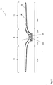
- FIG. 1 shows in a sectional view of a lamp assembly 1, which comprises an elongated circuit board 20, on the center of a plurality of LEDs 30 in series with a predetermined pitch (pitch) are arranged.
- an elongate optical element 10 is formed with laterally successive light guiding and light directing sections in the central portion Z and the lateral areas L1a and L1b to produce a predetermined light distribution function.
- the optical element has a barrel-vault-like cross-section in the central portion Z, the inner side wall surface of which may extend substantially to the board, so that the LED array is received and protected in the dome-like cavity.
- adjoining both outer side wall sections of the barrel-vault-like central section are two wing-like lateral sections, which are each formed by sections L1a and L1b.
- the generated light areas are indicated in the figure by the reference symbols B and E1, where B denotes the actual illumination area with high illumination luminous flux and E1 a luminance area with possibly lower viewing angle dependent lower luminous flux, which laterally adjoins the illumination area and serves to provide a contrast reducing brightening light , All areas together generate the desired luminous flux distribution on the surface to be illuminated.
- the optical element 10 is formed in the described embodiment of a transparent material such as PMMA or PC, in particular by means of an injection molding process or an extrusion process.
- the row arrangement of the LEDs 30 is aligned in the lateral direction centrally to the central portion Z of the optical element 10. Visible, this central portion Z in the embodiment according to. Fig. 1 formed with a refractive structuring in the form of approximately a convex-concave lens to produce the predetermined illumination luminous flux in the emission direction behind the optical element 10.
- the arranged on both sides of the central portion Z lateral portion L1 in the form of the two wing-like projections is formed in each case by an optical fiber region L1a and a Auskoppel Scheme L1b, the latter guided by the laterally inner optical fiber region L1a light via total reflection farther outward and arranged on its surface optical decoupling elements decoupling brightening light.
- a part of the light emitted by the LEDs 30 transmits, starting from the central section into the light guide region L1a, wherein this light component can be set by designing the transition between the central section Z and the light guide region L1a.
- the light assembly 1 is designed so that in the two laterally arranged to the central portion lateral sections total between 1 - 50% of the total luminous flux of the LEDs 30 is introduced, insofar the luminous flux in the lighting area is depending on the embodiment, neglecting losses such as scattering and absorption between 50 and 99%.
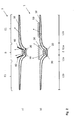
- FIGS. 2a, 2b illustrated lamp assemblies 1 are basically identical to the embodiment according to the circuit board 20, the LEDs 30 and the one-piece optical element 10 Fig. 1 educated.
- the in FIG. 2a illustrated embodiment in the beam direction behind the optical element in the region of the lateral boundaries of the central portion Z two planar and with the optical element 10 in the longitudinal direction extending reflectors 40 at a predetermined angle to the center axis.
- the desired light distribution within the illumination area B is set by the successive action of the refractive structuring of the optical element 10 in the central portion and the subsequent light deflection by the reflectors 40.
- FIG. 2b again in cross-section perpendicular to the longitudinal direction indicated embodiment of a lamp assembly 1 in the beam direction behind the optical element 10 prism means 50 both on the central portion Z and on the Auskoppel Scheme L1b of the lateral portion L1 of the optical element on for further light guidance.
- the optical element 10 together with one or more light-guiding elements, for example a prism device 50 in the region of the lateral portion L1 gem.
- Fig. 2b be set integrally.
- FIG. 3 shows in a perspective view of a light assembly 1 with a board 20 and an optical element 10, which in the described embodiment on its, the circuit board facing away from the outside and thus in the emission direction a Auskoppel Modelltechnik in the form of elevations or depressions, through which the light guided within the volume of the lateral portion is coupled out.
- the inner interface 11 and the outer interface 12 for the radiation emitted by the LEDs form a convex lens for the predetermined adjustment of the illumination luminous flux in the illumination area.
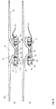
- FIG. 4a, 4b show further embodiments of a light assembly in a sectional view, which are designed with respect to the design and arrangement of board 20, the array of LEDs 30 and the optical element 10 except for the differences described below the same, here exemplary fastenings of the optical element 10 at the board 20 are shown.
- the optical element 10 in the conductor region L1a of the lateral portion holding arms 13 which are designed to cooperate with holding elements 70 which sit on both sides of the LED row on the board 20 and extending with projections 21 therethrough, for example, for fixing the entire lamp assembly on a housing.
- the support arms 13 have in the cross-sectional representation of the plane of symmetry of the optical element 10 in the described embodiment at an angle of about 45 ° extending and resilient support arm, at its end a latching surface 13a is arranged, which with an associated latching surface 71a on a latching cam 71st cooperates to secure the optical element which extends transversely on the holding element 70 to the outside.
- the optical element 10 of FIGS. 4a, b has in the lateral outcoupling section L1b (s. Fig. 1 ) on its side facing the LED on a Auskoppel Quilttechnik 61 in the form of longitudinally and mutually parallel grooves, which ensure that light is deflected out of the total reflection condition and at the opposite interface the optical element for providing the with respect to FIG. 1 leaves the luminance area E1 described.
- Example given further extend in the transverse direction over the central portion Z and the light guide region L1a of the lateral section L1 (see Figure 1) raster elements 55 of a light grid to provide a glare for the viewer.
- the optical element, following the central section Z has on both sides a respective lip 15 extending over the entire longitudinal extent, which rests on the board 20.
- the optical element 10 differs from that of the embodiment according to FIG. 4a Only in relation to the attachment to the board 20 and the holding member 70.
- a resilient support arm 13 is here a extending to the board 20 extending projection 14 which on the one hand can provide a seal of the LED row receiving cavity and the another a contact surface 14a for an internal locking cam 71, which is arranged pointing radially inwardly on the retaining element 70.
- FIG. 5 shows a further embodiment of a lamp assembly 1, which has a light grid in the region of the central portion Z and the light guide region L1a, of which a single locking element 55 is indicated in the sectional view.
- a lamp assembly 1 which has a light grid in the region of the central portion Z and the light guide region L1a, of which a single locking element 55 is indicated in the sectional view.
- the light grid is in the central portion Z beyond a reflector device similar to the in FIG. 2a shown with two longitudinally extending reflectors 40th
- FIG. 5 In order to increase the proportion of the light directed into the lateral section L1, the in FIG. 5 given embodiment of the optical element at the outer boundary surface 12 of the central portion Z a centrally extending in the longitudinal direction wedge-shaped recess 16 as an additional and integral with the optical element 10 formed light-guiding element.
- a light grid with individual grid elements 55 which is perpendicular to the longitudinal extent of the lamp assembly and over the transverse extent of the central section Z and the two light guide areas L1a (see FIG. Fig. 1 ).
- fins 56 are provided on the outer surfaces of both light guide regions, which alternate with the raster elements in the specified embodiment and do not extend into the central section.
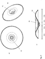
- FIGS. 7a to 7c show a light assembly, which is designed rotationally symmetrical, wherein a single LED or a plurality of LEDs are arranged on a circular surface on the board.
- a cup-like reflector 41 is placed in the central portion of the optical element for adjusting a predetermined illumination luminous flux together with the refractive properties of the central portion Z of the optical element 28.
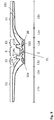
- FIG. 8 shows in a sectional view perpendicular to the longitudinal extent of an embodiment of an inventive elongate light assembly.
- the LED arrangement comprises an elongated circuit board 20, which has centrally a primary LED structure in the form of an LED row 31, which are laterally spaced apart on both sides of a respective secondary LED structure in the form of an LED row 32a, b assigned.
- the LEDs of the primary LED structure and the LEDs of the secondary LED structure are independently controllable and also have a different color temperature.
- the color temperature of the middle LED row 31 is lower than the color temperature of the laterally spaced LED rows 32a, b.
- the secondary LEDs emit a cool white light in the described embodiment, the primary LEDs emit a warm white light.
- primary and secondary LEDs can have different spectral emission spectra.
- the two lateral sections L1 arranged at a distance from the longitudinal axis of the optical element 110, each comprising a coupling-out region L1b and an optical waveguide region L1a, are designed essentially identical to those of the embodiments described above. In this respect, they can also have the above-described light-guiding elements, such as the prism device or the decoupling elements described. The same applies to the central portion Z, in which the predetermined illumination luminous flux is designed to provide the illumination area B.
- the optical element has three dome-shaped cavities corresponding to the three rows of LEDs, which receive the arranged on the board LED rows.
- the distance between the LEDs and the surface of the optical element 110 defining the respective dome cavity and directed towards the printed circuit board corresponds to the distance between adjacent LEDs of a row. Accordingly, it is Fig. 8 can be seen that the distance between adjacent LEDs of the primary structure is slightly larger is that of the spacing of adjacent LEDs of the secondary structure, since the LEDs of the middle row 31 have a greater distance from the optical element than the adjacent rows 32a, b.
- the optical element 110 of the lamp assembly according to FIG. 8 configured so that the light of the primary LED row 31 is emitted alone in the illumination area B. Recognizable points in the FIG. 8 indicated optical element 110 between the central portion and the lateral portion on an intermediate portion L1c, in which the light of the secondary LED row 32a, b coupled on the one hand in the conductor region L1a of the lateral portion, but partly also in a extending in the beam direction wall portion 115 at its Limiting surfaces 115a, 115b, the light is totally reflected until it penetrates the here approximately parallel to the board 20 extending boundary surface and leaves the acting as a light guide wall portion 115.
- the regions arranged laterally to the central section are formed symmetrically with respect to the longitudinal center, so that a symmetrical emission behavior is established in the two luminance areas E1.
- the luminaire module according to FIG. 8 is particularly suitable for providing, in addition to the illumination area B with a high luminous flux, also a luminance area E1 for emitting contrast-reducing brightening light, wherein the height of the luminous flux can be adapted in particular to the daily cycle. It can also be provided to equip the secondary LED rows 32a, 32b with LEDs which have a variable color temperature, so that, for example, in the morning the brightening can be adjusted with light high color temperature and reduces the intensity of the fill light during the day and / or Color temperature of the Brilliant adapted to the physiological needs, in particular lowered and adapted to the color temperature of the lighting area B.
- FIG. 9 shows in a sectional view perpendicular to the longitudinal extent of a further embodiment of an inventively designed, elongated lamp assembly, which similar to the FIG. 8 is shown constructed.
- the LED array placed on the board 20, comprising a primary LED structure and, laterally spaced therefrom laterally spaced apart on both sides, a secondary LED structure may be identical to that described with reference to FIG FIG. 8 be described LED arrangement including the illustrated variants.
- the individual rows of LEDs are each again surrounded by the optical element 111 in the manner of a barrel vault, wherein the central section Z and the lateral section L1 or the light guide section L1a, like the coupling-out section L1b, are substantially identical to the design of the optical element 28 of FIG FIG. 8 is trained.
- the intermediate region L1d which is embodied here by the design of corresponding optical guiding regions and surfaces such that between the illumination region B, with which the luminous flux is determined by the light of the primary LED structure and in the Luminance E1, in which the luminous flux is determined by the light of the secondary LED structure, a second luminance area E2 is generated.
- the luminous flux in this area is determined by light from the first primary structure and the second primary structure.
- the intermediate regions L1d of the optical element 111 each define a type of mixing chamber into which light from the central LED row 31 and the respective adjacent LED row 32a or 32b is brought together.
- the barrel-vault-like sections of the individual LED rows of the optical element 111 for the LED rows additional optical light-guiding elements in the form of total reflection surfaces over which the respective light parts are deflected into the wall section 116.
- the two intermediate regions L1d are similar to those in FIG FIG. 8 illustrated embodiment acting as a light guide and extending in the beam direction wall portion 116, on whose boundary surfaces 116a, b light is totally reflected until it emerges from the wall portion 116 at the front interface. Both wall sections 116 extend over the entire optically effective longitudinal extent of the optical element 111.
- a further embodiment of a light assembly according to the invention is designed, which in turn is elongated and has an LED array having a series arrangement with a predetermined sequence of LEDs of the primary LED structure and LEDs of the secondary LED structure.
- a single LED follows the secondary LED structure, etc.
- a plan view of a thus designed luminaire assembly according to the invention with a view of the optical element 112 shows FIG. 10 ,
- both LED types 120a, 120b may have a different color temperature or spectral emission behavior and / or different control circuits.
- the optical element 112 has an optical design adapted in accordance with the sequence of primary and secondary LEDs such that the light of the primary LEDs 120a is used to form the illumination luminous flux B, while the light of the secondary LEDs 120b is used to design the luminous flux in the luminance area E1 is used.
- the geometric design of the optical element 112 for generating the indicated luminous areas is in FIG. 11a , b indicated, which the respective section through the in FIG. 10 drawn planes S1-S1 and S2-S2 show.
- the optical element 112 is formed in the cutting plane S1-S1 to produce the illumination area B, see FIG. 11b .
- the entire light of the primary LEDs 120a is used to generate the illumination luminous flux B, while the light of the LEDs of the secondary LED structure is used to generate the luminance area E1.
Description
- Die Erfindung betrifft eine Leuchtenbaugruppe nach dem Oberbegriff nach Anspruch 1.
- Mit der Einführung von LEDs in Beleuchtungsvorrichtungen sowohl im gewerblichen als auch im privaten Bereich sind optische Systeme gestaltbar, welche aufgrund der Punktförmigkeit des Leuchtmittels eine vergleichsweise geringe, blendfreie Lichtaustrittsfläche aufweisen, beispielsweise bereitgestellt unter Verwendung von Linsen, Mikroraster oder Reflektoren. Derartige Systeme weisen eine vergleichsweise kompakte Bauform auf und erlauben eine exakte Lenkung bzw. Führung des Lichtes zur Erzeugung einer spezifischen Lichtverteilung oder normativen Entblendung. Typisch für derartige optische Systeme ist es jedoch, dass außerhalb der in der Norm beschriebenen Bereiche einer Blendungsbegrenzung, unter Umständen aufgrund der hohen Güte der optischen Systeme, hohe Kontraste und Leuchtdichten entstehen, welche vom Betrachter als extrem störend empfunden werden können.
- Zur Vermeidung dieses Problems wurden optische Systeme für LED-Leuchten vorgeschlagen, bei welchen um die eigentliche Lichtaustrittsfläche der Optik herum eine leuchtende Fläche vorgesehen ist, deren Leuchtdichte den Kontrast mildert. Diese Umgebungsleuchtdichte wird bei den bekannten Leuchten durch eine Hinterleuchtung erzeugt, welche den Herstellungsaufwand und damit die Kosten der Leuchte erhöht.
- Die Offenlegungsschrift
US 2013/0051066 A1 betrifft eine Beleuchtungseinrichtung, umfassend Lichtquellen, eine Lichtführungsplatte zum Führen von Licht der Lichtquellen sowie ein Gehäuse zu Halten der Lichtquellen und der Lichtleitplatte, wobei die Beleuchtungseinrichtung mittig ein Befestigungsteil aufweist. Die Lichtleitplatte und die Lichtquellenanordnung sind derart gestaltet und zueinander angeordnet, dass sich eine gleichförmige Lichtabgabe über die gesamte Erstreckung der Beleuchtungseinrichtung einstellt. - Die Offenlegungsschrift
DE 10 2010 027 648 A1 betrifft eine Signalleuchteneinheit für einen Fahrzeugaußenspiegel, die eingerichtet ist, eine Lichtabstrahlung in Fahrtrichtung und entgegen der Fahrtrichtung bereitzustellen. Hierzu weist die Signalleuchteneinheit eine Anzahl von länglichen Lichtleitkörpern und eine Anzahl von zugeordneten Leuchtmitteln zum Beleuchten eines Einkoppelabschnittes des zugeordneten Lichtleitkörpers auf. In einer Ausführungsvariante umfasst die Signalleuchteneinheit zwei Leuchtenmittel sowie zwei länglich ausgeführte Lichtleitkörper, wobei den Leuchtmitteln jeweils ein Lichtleitkörper zugeordnet ist. Die OffenlegungsschriftEP 2 796 769 A2 betrifft eine LED-Leuchte mit einer plattenartigen Lichtleiter-Anordnung mit einer Öffnung, wobei die LED-Lichtquelle so angeordnet ist, dass ein erster Teil des Lichtes über die Öffnung abgegeben wird und ein zweiter Teil des Lichtes über einen Umfangsrand der Öffnung in die Lichtleiter-Anordnung eingekoppelt wird und im weiteren über eine Flachseite der Lichtleiteranordnung abgegeben wird. - Der Erfindung liegt die Aufgabe zugrunde, eine Leuchtenbaugruppe für eine Leuchte bereitzustellen, welche herkömmlicher Leuchten bzw. Leuchtenbaugruppen mit punktförmigen Lichtquellen in Bezug auf den beschriebenen Nachteil verbessert. Diese Aufgabe löst die Erfindung mit einer Leuchtenbaugruppe mit den Merkmalen von Anspruch 1. Dabei zeichnet sich die erfindungsgemäße Leuchtenbaugruppe dadurch aus, dass Lichtquellen der primären Lichtquellen-Struktur und Lichtquellen der sekundären Lichtquellen-Struktur ein unterschiedliches Emissionsspektrum und/oder getrennt ansteuerbare Stromversorgungen aufweisen.
- Zweckmäßigerweise kann auch der Auskoppelbereich zum Leiten bzw. Führen des Lichtes insbesondere in lateraler Richtung ausgebildet sein, sodass die Auskopplung von Licht über den lateral ausgedehnten Auskoppelbereich erfolgen kann.
- Durch die angegebene Gestaltung der erfindungsgemäßen Leuchtenbaugruppe bzw. des erfindungsgemäß gestalteten optischen Elementes wird eine kompakte und kostengünstige Bauform der gesamten Baugruppe bereitgestellt, bei welcher zumindest in einer Vielzahl von Ausführungsformen das für den eigentlichen Beleuchtungslichtstrom verantwortliche Leuchtmittel in exakt vorgebbarer Weise durch die Verwendung von insbesondere lateralen Lichtleit- und Lichtlenkabschnitten auch den Lichtteil zur kontrastvermindernden Aufhellung in Querrichtung zum gerichteten Beleuchtungslichtstrom bereitstellt. Dabei kann Licht insbesondere im Zentralabschnitt und/oder in dessen Randbereich aufgenommen und in zum Zentralabschnitt lateral beabstandete Bereiche geführt und dort ausgekoppelt werden. Darüber hinaus ist es mit der erfindungsgemäßen Leuchtenbaugruppe nun möglich, auf konstruktiv einfache und kostengünstige Weise mehrere Leuchtenareale bei einer Leuchte bereitzustellen, welche speziell auf die physiologischen Bedürfnisse des Menschen einstellbar sind. Bei solchen Ausführungsformen, bei welchen der Lichtstrom, der zur Kontrastverminderung verwendet wird, von der gleichen Lichtquelle wie der Lichtstrom für den eigentliche Beleuchtungslichtstrom stammt, verteilt sich der gesamte Lichtstrom auf beide Bereiche. Auf diese Weise reduziert sich der Lichtstrom aus dem Zentralabschnitt was insbesondere bei der Verwendung von hocheffizienten Energiequellen wie LEDs vorteilhaft sein kann.
- Die erfindungsgemäße Baugruppe kann mit allen bekannten punktförmigen Lichtquellen wie Licht emittierenden Halbleitereinrichtungen, insbesondere Halbleiterdioden wie LEDs oder Laserdioden realisiert sein, wobei der Halbleiter ein organischer oder nichtorganischer Halbleiter sein kann. Der Einfachheit halber wird im Folgenden die Angabe "LED" verwendet; diese Angabe ist in der vorliegenden Anmeldung als beispielhaft anzusehen und kann jede punktförmige Lichtquelle meinen, insbesondere auch eine Laserdiode.
- Dabei weist die Lichtquellenanordnung-Anordnung der erfindungsgemäßen Baugruppe eine primäre LED-Struktur und eine sekundäre LED-Struktur auf, wobei LEDs der primären LED-Struktur und LEDs der sekundären LED-Struktur eine unterschiedliche Lichtfarbe bzw. spektrales Emissionsverhalten und/oder getrennt ansteuerbare Stromversorgung aufweisen. Es kann vorgesehen sein, dass alle LEDs der primären LED-Struktur gleichartige LEDs aufweisen, insbesondere in Bezug auf ihre elektrischen und/oder Lichtemissionseigenschaften. In ähnlicher Weise kann vorgesehen sein, dass die LEDs der sekundären LED-Struktur gleichartige LEDs umfassen. Zweckmäßigerweise können sowohl die primäre als auch die sekundäre LED-Struktur auf einem einzelnen LED-Träger wie einer Leiterplatte angeordnet sein, wobei sie sich auch in Bezug auf ihre örtliche Anordnung zueinander unterscheiden können.
- Die Bereitstellung von unterschiedlichen Leuchtmitteln kann insbesondere genutzt werden, um zum eigentlichen Beleuchtungslichtstrom zusätzliche Leuchtdichtenareale mittels Lichtauskoppelflächen im Bereich der Lateralabschnitte des optischen Elements bereitzustellen, welche sich von dem Beleuchtungsareal in Bezug auf die Stärke des Lichtstromes und/oder in Bezug auf die Wellenlänge des abgegebenen Lichtes unterscheiden. Dabei können diese Lichtdichteareale nicht nur zur Kontrastverminderung beitragen, sondern auch eine an den Tagesrhythmus angepasste und damit an die Physiologie des Menschen angepasste Beleuchtung bereitstellen.
- Weitere vorteilhafte Merkmale sind in der nachfolgenden allgemeinen sowie der speziellen Beschreibung und den Unteransprüchen angegeben.
- Die Grundform der erfindungsgemäßen Leuchtenbaugruppe bzw. des diesbezüglichen optischen Elementes kann flexibel an die jeweilige Beleuchtungsaufgabe angepasst sein, beispielsweise mit einer kreisförmigen Grundfläche oder einer langgestreckten, insbesondere rechteckförmigen Grundfläche.
- Zweckmäßigerweise kann die erfindungsgemäße Leuchtenbaugruppe langgestreckt ausgebildet sein, wobei die LED-Anordnung zumindest eine mittlere Reihenanordnung von LEDs der primären LED-Struktur aufweisen kann. Dabei kann beidseitig zur Längserstreckung jeweils zumindest eine zur mittleren Reihenanordnung der primären LED-Struktur lateral beabstandete Reihenanordnungen von LEDs der sekundären LED-Struktur angeordnet sein. Es ist darauf hinzuweisen, dass sowohl die mittlere Reihenanordnung von LEDs der primären LED-Struktur als auch die jeweilige hierzu lateral beabstandete Reihenanordnung von LEDs der sekundären LED-Struktur selbst mehrere, insbesondere parallel verlaufende Reihen von LEDs aufweisen können. In der einfachsten Ausführungsform weisen alle Reihenanordnungen jeweils eine Mehrzahl von in einer einzelnen Reihe nebeneinander angeordneten LEDs auf.
- Zur Erzielung der gewünschten Lichtstromverteilung ist das optische Element an die jeweilige Anordnung der primären LED-Struktur und der sekundären LED-Struktur angepasst. Insbesondere kann zweckmäßigerweise die mittlere Reihenanordnung von LEDs der primären LED-Struktur auf der Leiterplatte zu dem des optischen Elementes derart angeordnet sein, dass Licht der primären LEDs in eine Lichteintrittsfläche des Zentralabschnitts eingekoppelt und an dessen Austrittsfläche ausgekoppelt wird. Dabei kann vorgesehen sein, dass bei der beschriebenen Reihenanordnung von LEDs der primären LED-Struktur der Zentralabschnitt über die wirksame Längserstreckung des optischen Elementes identisch ist, d.h. die Gestaltung des Zentralabschnitts in Querrichtung unabhängig vom Längsort des optischen Elementes gestaltet ist.
- Zweckmäßigerweise kann dies auch für die Gestaltung der Lateralabschnitte des optischen Elementes gelten, welche in den beschriebenen Reihenanordnungen der sekundären LED-Struktur angeordnet sein können. Insofern kann es zweckmäßig sein, wenn beidseitig zum Zentralabschnitt des optischen Elements jeweils ein Lateralabschnitt mit einem Lichtleiterbereich und einem Auskoppelbereich gestaltet ist, welcher jeweils ein lichtauskoppelndes Leuchtdichteareal bereitstellt zur Abgabe von kontrastverminderndem Aufhelllicht. Wie obenstehend schon ausgeführt kann dabei der Auskoppelbereich auch zum Leiten bzw. Führen des Lichtes insbesondere in lateraler Richtung ausgebildet sein, sodass der Auskoppelbereich lateral ausgedehnt sein kann. Dabei kann die Reihenanordnung von LEDs der sekundären LED-Struktur zu dem jeweils zugeordneten Lateralabschnitt so angeordnet sein, dass Licht der sekundären LEDs jeweils an einer Lichteintrittsfläche in den Lichtleiterbereich eines Lateralabschnitts eingekoppelt und im Auskoppelbereich ausgekoppelt wird, wobei der Auskoppelbereich durch einen Lichtleiterbereich, in welchem keine bzw. nur eine vernachlässigbare Lichtauskopplung erfolgt, vom Zentralbereich lateral beabstandet sein kann.
- In einer zweckmäßigen, abgewandelten Ausführungsform kann das optische Element im Bereich eines Übergangs vom Zentralabschnitt in einen Lateralabschnitt so gestaltet, dass auch Licht der primären LED-Struktur in einen Lateralabschnitt eingeführt und in den Auskoppelbereich geleitet wird, wo es zusammen mit dem Licht der sekundären LED-Struktur ein zum Zentralabschnitt den Kontrast verminderndes Leuchtdichteareal bereitstellt. Insofern kann das am Auskoppelbereich des Lateralabschnittes das optische Element verlassende Licht ein Mischlicht sein, beispielsweise Anteile eines hauptsächlich in den gerichteten Beleuchtungslichtstrom geleiteten warmweißen Lichtes mit niedriger Farbtemperatur von LEDs der primären LED-Struktur und Licht mit höherer Farbtemperatur von LEDs der sekundären LED-Struktur umfassen. In solchen vorteilhaften Ausführungen der Erfindung, in welchen die primäre und die sekundäre LED-Struktur unabhängig voneinander ansteuerbar sind, kann zweckmäßigerweise ein Tag-Nacht-Rhythmus simuliert werden, indem beispielsweise der Anteil des Lichtes mit hoher Farbtemperatur der LEDs der sekundären LED-Struktur im Laufe des Tages reduziert oder gar abgeschaltet wird zur Anpassung an die Physiologie des Menschen. Es kann ferner zweckmäßig sein, wenn in Querrichtung zwischen Zentralabschnitt und Lateralabschnitt des optischen Elements jeweils ein intermediärer Abschnitt mit einer Lichteinkoppelfläche zur Einkopplung von Licht der primären LED-Struktur und zur Einkopplung von Licht der sekundären LED-Struktur und einer Lichtauskoppelfläche zur Bereitstellung eines weiteren Leuchtdichteareals für die Auskopplung von Licht der beiden LED-Strukturen gestaltet ist. Bei dieser Ausführungsform kann der Lateralabschnitt des optischen Elementes so gestaltet sein, dass das von diesem bereitgestellte Leuchtdichteareal im Wesentlichen nur Licht der sekundären LED-Struktur aufweist.
- Diese Ausführungsform eignet sich insbesondere in solchen Fällen, bei welchen die LED-Strukturen wie obenstehend beschrieben in Reihe angeordnet sind. Das optische Element der erfindungsgemäßen Leuchtenbaugruppe kann dabei in Querrichtung zwischen dem Zentralabschnitt und den Lateralabschnitten jeweils einen intermediären Abschnitt mit einer Lichteinkoppel- und Lichtauskoppelfläche zur Bereitstellung eines weiteren Leuchtdichteareals zur Einkopplung von Licht aus der primären LED-Struktur und der sekundären LED-Struktur und zur Auskopplung beider Lichtanteile aufweisen. Eine solche Baugruppe, respektive das zugeordnete optische Element, kann demnach so gestaltet sein, dass der Zentralabschnitt ein Leuchtdichteareal für die Beleuchtungszwecke mit Licht von LEDs der primären LED-Struktur, der intermediäre Abschnitt ein Leuchtdichteareal für Mischlicht zur Aufhellung und der Lateralabschnitt ein Leuchtdichteareal mit Licht von LEDs der sekundären LED-Struktur zur Aufhellung bzw. zur Realisierung einer Tag/Nacht-Simulation bereitstellen.
- Bei einer derartigen Gestaltung des optischen Elementes kann dieses neben der Lichtaustrittsfläche im Zentralabschnitt für den gerichteten Beleuchtungslichtstrom zu beiden Seiten jeweils zwei in Querrichtung beabstandete Leuchtdichteareale aufweisen, wobei das außen liegende, durch den Lateralabschnitt bereitgestellte Areal Licht mit einer hohen Farbtemperatur abgeben kann, das beispielsweise nachmittags abschaltbar ist. Dann kann das innen liegende Leuchtdichteareal, welches durch den intermediären Abschnitt bereitgestellt wird, für eine Kontrastminderung sorgen mittels einer Abstrahlung von Licht gleicher Farbtemperatur wie die des gerichteten Beleuchtungslichtstromes im Zentralabschnitt und damit für eine Reduzierung der psychologischen bzw. physiologischen Blendung.
- Dabei kann das optische Element und die relative Anordnung zu den LED-Strukturen so ausgebildet sein, dass allein die Lateralabschnitte mit Licht der LEDs der sekundären LED-Struktur, insbesondere kaltweißem Licht zur Erzeugung eines großflächigen Leuchtdichteareal gespeist werden, dessen Lichtstrom wie beschrieben zum Abend hin auf null reduziert werden kann, um einen gesunden Schlaf zu ermöglichen.
- Insbesondere zur Bereitstellung einer schmalen Bauform der erfindungsgemäßen Leuchtenbaugruppe kann auch vorgesehen sein, die LED-Anordnung so auszubilden, dass sie zumindest eine, in Längserstreckung des optischen Elementes verlaufende Reihe, insbesondere eine einzelne Reihe von hintereinander angeordneten LEDs aufweist, wobei LEDs der primären LED-Struktur in einer vorgegebenen Abfolge sich mit LEDs der sekundären LED-Struktur abwechseln. Die vorgegebene Abfolge kann beliebig gestaltet sein, beispielsweise so, dass auf eine LED der primären LED-Struktur eine LED der sekundären LED-Struktur in Längsrichtung folgt. Es ist jedoch auch jede andere Abfolge möglich, beispielsweise auf zwei in Reihe angeordneten LEDs der primären LED-Struktur folgen zwei in Längsrichtung nebeneinander angeordneten LEDs der sekundären LED-Struktur. Zweckmäßigerweise können lateral aufeinander folgende Lichtleit- und Lichtlenkabschnitte des optischen Elements in Längsrichtung an die Abfolge der primären LEDs und sekundären LEDs derart angepasst sein, dass an einem Längsort mit einer primären LED der Zentralabschnitt eine refraktive Strukturierung zur Lichtein- und Lichtauskopplung für die Bereitstellung des gerichteten Beleuchtungslichtstromes sowie einen Lateralabschnitt mit einem Lichtleiterbereich und einem Auskoppelbereich umfasst, wobei letzterer wiederum auch zur Lichtführungs- bzw. Lichtleitung ausgebildet sein kann, damit der Auskoppelbereich lateral ausgedehnt sein kann. Je nach spezifischer Ausführung des optischen Elementes kann die Ausgestaltung so sein, dass kein Licht der primären LED in Lateralabschnitte eingeführt wird. In einer anderen Ausführungsform kann jedoch, wie obenstehend schon beschrieben tatsächlich vorgesehen sein, dass die Gestaltung der Lichtleit- und Lichtführungsabschnitte des optischen Elementes derart ausgeführt ist, dass auch in einen Lateralabschnitt Licht der primären LEDs geführt und abgegeben wird.
- Diese Anpassung der lateral aufeinander folgenden Lichtleit- und Lichtlenkabschnitte des optischen Elements in Längsrichtung an die Abfolge der primären LEDs und sekundären LEDs kann auch umfassen, dass an einem Längsort mit einer sekundären LED ein Mittenabschnitt ausgebildet ist, in welchem Licht in das optische Element eingekoppelt, jedoch in diesem Mittenabschnitt nicht ausgekoppelt wird. Stattdessen kann das Licht vom Mittenbereich in einen Lateralabschnitt mit einem sich lateral erstreckenden Lichtleiterbereich und einem Auskoppelbereich umgelenkt werden zur Bereitstellung eines Leuchtdichteareals im besagten Lateralabschnitt.
- Zweckmäßigerweise können neben dem optischen Element der Leuchtenbaugruppe weitere Lichtleit- bzw. Lichtlenkbauteile Verwendung finden, um eine noch genauere Richtung und Führung des Lichtes bereitzustellen. Beispielsweise kann in Abstrahlrichtung des LEDs hinter dem optischen Element ein zusätzliches Lichtlenkelement wie ein quer über den Lateralabschnitt beschränkter Diffusor oder eine Prismenplatte angeordnet sein, um über den Lateralabschnitt insbesondere kaltweißes Licht großflächig und möglichst diffus abzustrahlen, was physiologisch vorteilhaft sein kann. Ferner kann zur Gestaltung einer vorgegebenen Lichtverteilung oder eines Blendschutzes innerhalb des Beleuchtungslichtstromes vorgesehen sein, in Abstrahlrichtung hinter dem optischen Element ein zusätzliches Lichtlenkelement wie ein lateral über dem Zentralabschnitt beschränktes Lichtraster, ein Lamellenraster oder eine Reflektoreinrichtung anzuordnen.
- In bestimmten Ausführungen kann es auch möglich sein, derartige zusätzliche Lichtlenkelemente integral mit dem beschriebenen optischen Element herzustellen, beispielsweise in Form eines Mehrkomponenten- oder Mehrfarbenspritzgusses. Zur optimalen Gestaltung des Lateralabschnitts des optischen Elementes kann dieses in seinem lichtführenden Bereich mit einem transparenten Material und in seinem auskoppelnden Bereich mit einem transluzenten Material ausgebildet sein, beispielsweise mittels Koextrusion oder Mehrkomponentenspritzen.
- Die Anordnung derartiger zusätzlicher Lichtlenkeinrichtungen ist nicht in jedem Fall über den Zentralabschnitt bzw. den Lateralabschnitt des optischen Elementes beschränkt. In einer besonders zweckmäßigen Ausführungsform kann auch vorgesehen sein, ein Licht- oder Lamellenraster in Querrichtung über den Zentralabschnitt und den Lichtführungsbereich des Lateralabschnitts anzuordnen. Diese Gestaltung kann insbesondere in solchen Ausführungsformen zweckmäßig sein, bei welchen sich der Lichtführungsbereich des Lateralabschnitts vom Zentralabschnitt nicht nur mit einer Querkomponente, sondern auch mit einer Längskomponente erstreckt, sodass einzelne Rasterelemente an der Außenwandung des Lichtführungsbereichs befestigbar sind.
- Die Auskoppelelemente an einer Oberfläche des Auskoppelbereichs des Lateralabschnitts können je nach Ausführungsform an der Vorder- und/oder Rückseite in Bezug auf die Abstrahlrichtung angeordnet sein, wobei diese bekannten Ausprägungen wie Erhebungen, Vertiefungen aufweisen, die beispielsweise auch durch Bedruckung oder Mattierung erzeugt werden können. Auch für die Gestaltung des refraktiven Zentralabschnittes ist eine Mehrzahl von spezifischen Ausführungen erfindungsgemäß möglich. Beispielsweise kann dieser als Linse oder mit lichtlenkenden Strukturen wie Prismen ausgeführt sein. Insbesondere bei solchen Leuchtenbaugruppen, in welchen die LED-Anordnung zumindest eine Reihe von LEDs umfasst, welche zueinander beabstandet sind, kann zweckmäßigerweise das optische Element an Lichtlenkenden Oberflächen eine Längsstrukturierung zur Auflösung der Punktstrahleigenschaften des Leuchtmittels umfassen.
- Die Leuchtenbaugruppe wird im Folgenden durch das Beschreiben einiger Ausführungsformen unter Bezugnahme auf die beiliegenden Figuren erläutert, wobei
- Figur 1
- in einer Prinzipskizze eine Leuchtenbaugruppe einer ersten Ausführungsform in einer Schnittdarstellung,
- Figuren 2a, b
- die in
Figur 1 angegebene Leuchtenbaugruppe in Kombination mit weiteren Lichtlenkelementen, - Figur 3
- eine andere Ausführungsform einer Leuchtenbaugruppe in einer perspektivischen Teilansicht,
- Figuren 4a, b
- zwei weitere, zu der in
Figur 1 angegebenen Ausführungsform insbesondere in Bezug auf Halteelemente spezifizierte Leuchtenbaugruppen, - Figur 5
- eine weitere Ausführungsform einer Leuchtenbaugruppe mit einer Mehrzahl von zum optischen Element weiteren Lichtlenkelementen in einer Schnittdarstellung,
- Figur 6
- eine weitere Ausführungsform einer Leuchtenbaugruppe mit einem speziellen Lichtraster in einer perspektivischen Ansicht,
- Figur 7a - c
- eine rotationssymmetrische Ausführungsform einer Leuchtenbaugruppe in einer Aufsicht, einer perspektivischen Ansicht sowie in einer Schnittdarstellung,
- Figur 8
- eine Ausführungsform einer erfindungsgemäßen Leuchtenbaugruppe, umfassend eine primäre und eine sekundäre LED-Struktur in einer Schnittdarstellung,
- Figur 9
- eine erfindungsgemäße und zur Ausführungsform gemäß
Figur 8 abgewandelte Leuchtenbaugruppe, - Figur 10
- eine Aufsicht auf eine weitere Ausführungsform einer erfindungsgemäß gestalteten, langgestreckten Leuchtenbaugruppe,
- Figur 11a
- eine Darstellung des in
Figur 10 angegebenen Schnittes S1-S1 senkrecht zur Längsachse, und - Figur 11b
- eine Darstellung des in
Figur 10 angegebenen Schnittes S2-S2 -
Figur 1 zeigt in einer Schnittdarstellung eine Leuchtenbaugruppe 1, welche eine langgestreckte Leiterplatte 20 umfasst, auf der mittig eine Vielzahl von LEDs 30 in Reihe mit vorgegebenem Abstand (pitch) angeordnet sind. In entsprechender Weise ist ein langgestrecktes optisches Element 10 gestaltet mit lateral aufeinanderfolgenden Lichtleit- und Lichtlenkabschnitten in dem Zentralabschnitt Z und den lateralen Bereichen L1a und L1b, um eine vorgegebene Lichtverteilungsfunktion zu erzeugen. Das optische Element weist im Zentralabschnitt Z einen tonnengewölbeartigen Querschnitt auf, dessen innere Seitenwandfläche sich im Wesentlichen bis zur Platine erstrecken kann, sodass die LED-Reihenanordnung in dem domartigen Hohlraum aufgenommen und geschützt ist. In der beschriebenen Ausführungsform schließen sich an beide äußeren Seitenwandabschnitte des tonnengewölbeartigen Zentralabschnittes zwei flügelartige Lateralabschnitte an, die jeweils durch Teilabschnitte L1a und L1b gebildet sind. - Die erzeugten Lichtareale sind in der Figur mit den Bezugszeichen B und E1 angegeben, wobei B das eigentliche Beleuchtungsareal mit hohem Beleuchtungslichtstrom und E1 ein Leuchtdichteareal mit ggf. blickwinkelabhängig, niedrigeren Lichtstrom bezeichnet, das sich lateral an das Beleuchtungsareal anschließt und zur Bereitstellung eines kontrastvermindernden Aufhelllichtes dient. Alle Areale erzeugen zusammen an der zu beleuchtenden Fläche die gewünschte Lichtstromverteilung. Das optische Element 10 ist in der beschriebenen Ausführungsform aus einem transparenten Material wie PMMA oder PC, insbesondere mittels eines Spritzgussverfahren oder eines Extrusionsverfahrens ausgebildet.
- Die Reihenanordnung der LEDs 30 ist in lateraler Richtung mittig zum Zentralabschnitt Z des optischen Elementes 10 ausgerichtet. Erkennbar ist dieser Zentralabschnitt Z in der Ausführungsform gem.
Fig. 1 mit einer refraktiven Strukturierung in Form etwa einer Konvex-Konkav-Linse ausgebildet, um den vorgegebenen Beleuchtungslichtstrom in Abstrahlrichtung hinter dem optischen Element 10 zu erzeugen. Der beidseitig zum Zentralabschnitt Z angeordnete Lateralabschnitt L1 in Form der beiden flügelartigen Fortsätze wird jeweils durch einen Lichtleiterbereich L1a und einen Auskoppelbereich L1b gebildet, wobei letzterer das vom lateral innen liegenden Lichtleiterbereich L1a geführte Licht über Totalreflexion weiter nach außen leitet und über, an seiner Oberfläche angeordnete optische Auskoppelelemente Aufhelllicht auskoppelt. Hierzu transmittiert ein Teil des von den LEDs 30 abgegebenen Lichtes, ausgehend vom Zentralabschnitt in den Lichtleiterbereich L1a hinein, wobei dieser Lichtanteil durch Gestaltung des Übergangs zwischen Zentralabschnitt Z und Lichtleiterbereich L1a einstellbar ist. - In der beschriebenen Ausführungsform ist die Quererstreckung des Zentralabschnitts Z kleiner als ein Sechstel, insbesondere kleiner als ein Achtel der Quererstreckung eines Lateralabschnitts L1=L1a + L1b, sodass für den Nutzer eine physiologisch sehr angenehmes, großflächiges und kontrastverminderndes Leuchtdichtdichteareal E1 benachbart zum Beleuchtungsareal bereitgestellt wird.
- Zweckmäßigerweise ist die Leuchtenbaugruppe 1 so gestaltet, dass in die beiden seitlich zum Zentralabschnitt angeordneten Lateralabschnitte insgesamt zwischen 1 - 50% des gesamten Lichtstromes der LEDs 30 eingeführt wird, insofern beträgt der Lichtstrom im Beleuchtungsareal je nach Ausführungsform bei Vernachlässigung von Verlusten wie durch Streuung und Absorption zwischen 50 und 99%.
- Die in den
Figuren 2a, 2b dargestellten Leuchtenbaugruppen 1 sind in Bezug auf die Leiterplatte 20, die LEDs 30 sowie das einstückige optische Element 10 grundsätzlich identisch zu der Ausführungsform gemäßFig. 1 ausgebildet. Darüber hinaus weist die inFigur 2a dargestellte Ausführungsform in Strahlrichtung hinter dem optischen Element im Bereich der lateralen Grenzen des Zentralabschnittes Z zwei flächige und sich mit dem optischen Element 10 in Längsrichtung erstreckende Reflektoren 40 mit vorgegebenem Winkel zur Mittenachse auf. Im Beleuchtungsareal B wird insofern durch das sukzessive Wirken der refraktiven Strukturierung des optischen Elements 10 im Zentralabschnitt und die nachfolgende Lichtlenkung durch die Reflektoren 40 die gewünschte Lichtverteilung innerhalb des Beleuchtungsareals B eingestellt ist. - Im Gegensatz zur Nutzung solcher Reflektoren weist die in
Figur 2b wiederum im Querschnitt senkrecht zur Längsrichtung angegebene Ausführungsform einer Leuchtenbaugruppe 1 in Strahlrichtung hinter dem optischen Element 10 Prismeneinrichtungen 50 sowohl über dem Zentralabschnitt Z als auch über den Auskoppelbereich L1b des Lateralabschnittes L1 des optischen Elementes auf zur weiteren Lichtlenkung auf. - In einer nicht dargestellten Ausführungsform kann das optische Element 10 zusammen mit einem oder mehreren Lichtlenkelementen, beispielsweise einer Prismeneinrichtung 50 im Bereich des Lateralabschnittes L1 gem.
Fig. 2b integral eingestellt sein. -
Figur 3 zeigt in einer perspektivischen Ansicht eine Leuchtenbaugruppe 1 mit einer Platine 20 sowie einem optischen Element 10, das in der beschriebenen Ausführungsform an seiner, der Platine abgewandten Außenseite und damit in Abstrahlrichtung eine Auskoppelstrukturierung in Form von Erhebungen oder Vertiefungen aufweist, durch welche das innerhalb des Volumens des Lateralabschnittes geführte Licht ausgekoppelt wird. Erkennbar bilden die innere Grenzfläche 11 und die äußere Grenzfläche 12 für die von den LEDs abgegebene Strahlung eine konvexartige Linse zur vorgegebenen Einstellung des Beleuchtungslichtstromes im Beleuchtungsareal. DieFiguren 4a, 4b zeigen weitere Ausführungsformen einer Leuchtenbaugruppe in einer Schnittdarstellung, die in Bezug auf die Gestaltung und Anordnung von Platine 20, der Reihenanordnung von LEDs 30 und des optischen Elementes 10 bis auf die nachfolgend beschriebenen Unterschiede gleich gestaltet sind, wobei hier beispielhafte Befestigungen des optischen Elements 10 an der Platine 20 dargestellt sind. In der Ausführungsform gemäßFigur 4a weist das optische Element 10 im Leiterbereich L1a des Lateralabschnitts Haltearme 13 auf, welche zum Zusammenwirken mit Halteelementen 70 ausgebildet sind, die beidseitig zur LED-Reihe auf der Platine 20 sitzen und sich mit Vorsprüngen 21 durch diese hindurch erstrecken, beispielsweise zur Befestigung der gesamten Leuchtenbaugruppe an einem Gehäuse. - Die Haltearme 13 weisen in der Querschnittsdarstellung zur Symmetrieebene des optischen Elementes 10 einen sich in der beschriebenen Ausführungsform im Winkel von etwa 45° erstreckenden und federnden Haltearm auf, an dessen Endbereich eine Rastfläche 13a angeordnet ist, welche mit einer zugeordneten Rastfläche 71a an einem Rastnocken 71 zum Befestigen des optischen Elementes zusammenwirkt, der sich am Haltelement 70 in Querrichtung nach außen erstreckt.
- Das optische Element 10 der
Figuren 4a, b weist im lateralen Auskoppelabschnitt L1b (s.Fig. 1 ) an seiner der LED zugewandten Seite eine Auskoppelstrukturierung 61 in Form von längs und parallel zueinander verlaufenden Rillen auf, welche dafür sorgen, dass Licht aus der Totalreflexionsbedingung herausgelenkt und an der gegenüber liegenden Grenzfläche das optische Element zur Bereitstellung des mit Bezug aufFigur 1 beschriebenen Leuchtdichteareals E1 verlässt. Bei dem inFigur 4a angegebenen Beispiel erstrecken sich ferner in Querrichtung über den Zentralabschnitt Z und den Lichtleiterbereich L1a des Lateralabschnittes L1 (siehe Figur 1) Rasterelemente 55 eines Lichtrasters zur Bereitstellung einer Entblendung für den Betrachter. Um die Reihenanordnung der LEDs 30 gegenüber äußeren Einflüssen wirkungsvoll zu schützen, weist das optische Element im Anschluss an den Zentralabschnitt Z beidseitig jeweils eine über die gesamte Längserstreckung verlaufende Lippe 15 auf, welche auf der Platine 20 aufliegt. - Bei der in
Figur 4b gezeigten Leuchtenbaugruppe unterscheidet sich das optische Element 10 von dem der Ausführungsform gemäßFigur 4a allein in Bezug die Befestigung mit der Platine 20 bzw. dem Halteelement 70. Statt eines federnden Haltearms 13 ist hier ein sich bis auf die Platine 20 erstreckender Vorsprung 14 vorgesehen, welcher zum einen eine Abdichtung des die LED-Reihe aufnehmenden Hohlraums bereitstellen kann und zum anderen eine Anlagefläche 14a für einen innen liegenden Rastnocken 71, der radial nach innen weisend am Halteelement 70 angeordnet ist. -
Figur 5 zeigt eine weitere Ausführungsform einer Leuchtenbaugruppe 1, die im Bereich des Zentralabschnitts Z und des Lichtleiterbereichs L1a ein Lichtraster aufweist, von welchem ein einzelnes Rastelement 55 in der Schnittdarstellung angegeben ist. Neben dem Lichtraster ist im Zentralabschnitt Z darüber hinaus eine Reflektoreinrichtung ähnlich der inFigur 2a gezeigten umfasst mit zwei sich in Längsrichtung erstreckenden Reflektoren 40. - Um den Anteil des in den Lateralabschnitt L1 gelenkten Lichtes zu erhöhen, weist die in
Figur 5 angegebene Ausführungsform des optischen Elementes an der äußeren Grenzfläche 12 des Zentralabschnittes Z eine zentrisch in Längsrichtung verlaufende keilförmige Ausnehmung 16 als zusätzliches und integral mit dem optischen Element 10 ausgebildetes Lichtlenkelement auf. - Bei der Ausführungsform gemäß
Figur 6 findet wiederum ein als zusätzliches Lichtlenkelement ein Lichtraster mit einzelnen Rasterelementen 55 Anwendung, welche senkrecht zur Längserstreckung der Leuchtenbaugruppe und über die Quererstreckung des Zentralabschnittes Z und der beiden Lichtleiterbereiche L1a (s.Fig. 1 ) verlaufen. Zur Verbesserung der Entblendungswirkung sind an den Außenflächen beider Lichtleiterbereiche Finnen 56 vorgesehen, welche sich mit den Rasterelementen in der angegebenen Ausführungsform abwechseln und sich nicht in den Zentralabschnitt hinein erstrecken. -
Figuren 7a bis 7c zeigen eine Leuchtenbaugruppe, welche rotationssymmetrisch gestaltet ist, wobei eine einzelne LED oder eine Mehrzahl von LEDs auf einer Kreisfläche auf der Platine angeordnet sind. Wie aus den Figuren hervorgeht, ist im Zentralabschnitt an das optische Element ein topfartiger Reflektor 41 platziert zur Einstellung eines vorgegebenen Beleuchtungslichtstromes zusammen mit den refraktiven Eigenschaften des Zentralabschnitts Z des optischen Elementes 28. Auch bei dieser Ausführungsform schließen sich in der Schnittdarstellung derFig. 7c ein Lichtleiterbereich L1a und ein Auskoppelbereich L1b an den Zentralabschnitt Z an.Figur 8 zeigt in einer Schnittdarstellung senkrecht zur Längserstreckung eine Ausführungsform einer erfindungsgemäß ausgebildeten langgestreckten Leuchtenbaugruppe. - Die LED-Anordnung umfasst eine langgestreckte Platine 20, welche mittig eine primäre LED-Struktur in Form einer LED-Reihe 31 aufweist, welcher lateral beabstandet zu beiden Seiten jeweils eine sekundäre LED-Struktur in Form einer LED-Reihe 32a, b zugeordnet sind. In der beschriebenen Ausführungsform sind die LEDs der primären LED-Struktur und die LEDs der sekundären LED-Struktur unabhängig voneinander ansteuerbar und weisen darüber hinaus eine unterschiedliche Farbtemperatur auf. Die Farbtemperatur der mittleren LED-Reihe 31 liegt niedriger als die Farbtemperatur der hierzu lateral beabstandeten LED-Reihen 32a, b. Die sekundären LEDs strahlen in der beschriebenen Ausführungsform ein kaltweißes Licht, die primären LEDs ein warmweißes Licht aus. Allgemein können primäre und sekundäre LEDs unterschiedliche spektrale Emissionsspektren aufweisen.
- Die beiden zur Längsachse des optischen Elementes 110 entfernt angeordneten Lateralabschnitte L1, umfassend jeweils einen Auskoppelbereich L1b sowie einen Lichtleiterbereich L1a, sind im Wesentlichen identisch zu denen der vorstehend beschriebenen Ausführungsformen ausgebildet. Insofern können sie auch die oben beschriebenen Lichtlenkelemente wie Prismeneinrichtung bzw. die beschriebenen Auskoppelelemente aufweisen. Gleiches gilt für den Zentralabschnitt Z, in welchem der vorgegebene Beleuchtungslichtstrom zur Bereitstellung des Beleuchtungsareals B ausgebildet ist. Das optische Element weist entsprechend den drei LED-Reihen drei domförmige Hohlräume auf, welche die auf der Platine angeordneten LED-Reihen aufnehmen.
- Zweckmäßigerweise entspricht bei der erfindungsgemäßen Ausführungsform der Abstand der LEDs zu der den jeweiligen Domhohlraum festlegenden und zur Platine gerichteten Fläche des optischen Elementes 110 dem Abstand zwischen benachbarten LEDs einer Reihe. Demnach ist
Fig. 8 entnehmbar, dass der Abstand benachbarter LEDs der Primärstruktur etwas größer ist als der der Abstand benachbarter LEDs der Sekundärstruktur, da die LEDs der mittleren Reihe 31 einen größeren Abstand zum optischen Element aufweisen als die benachbartes Reihen 32a, b. - Im Unterschied zu den mit Bezug auf die
Figuren 1 ,2a ,b undFigur 5 beschriebenen Ausführungsformen ist das optische Element 110 der Leuchtenbaugruppe gemäßFigur 8 so ausgestaltet, dass das Licht der primären LED-Reihe 31 allein in das Beleuchtungsareal B abgestrahlt wird. Erkennbar weist das inFigur 8 angegebene optische Element 110 zwischen dem Zentralabschnitt und dem Lateralabschnitt einen intermediären Abschnitt L1c auf, in welchem das Licht der sekundären LED-Reihe 32a, b einerseits in den Leiterbereich L1a des Lateralabschnitts eingekoppelt, jedoch teilweise auch in einen sich in Strahlrichtung erstreckenden Wandabschnitt 115 an dessen Begrenzungsflächen 115a, 115b das Licht totalreflektiert wird, bis es die hier etwa parallel zur Platine 20 verlaufende Begrenzungsfläche durchstößt und den als Lichtleiter wirkenden Wandabschnitt 115 verlässt. In der beschriebenen Ausführungsform sind die lateral zum Zentralabschnitt angeordneten Bereiche symmetrisch zur Längsmitte ausgebildet, sodass sich ein symmetrisches Abstrahlverhalten in den beiden Leuchtdichtearealen E1 einstellt. - Die Leuchtenbaugruppe gemäß
Figur 8 ist insbesondere geeignet, um neben dem Beleuchtungsareal B mit einem hohen Lichtstrom auch ein Leuchtdichteareal E1 zur Abgabe von kontrastverminderndem Aufhelllicht bereitzustellen, wobei die Höhe des Lichtstroms insbesondere an den Tageszyklus angepasst werden kann. Dabei kann auch vorgesehen sein, die sekundären LED-Reihen 32a, 32b mit LEDs auszustatten, welche eine veränderbare Farbtemperatur aufweisen, sodass beispielsweise morgens die Aufhellung mit Licht hoher Farbtemperatur eingestellt werden kann und im Laufe des Tages die Intensität des Aufhelllichtes vermindert und/oder die Farbtemperatur des Aufhelllichtes an die physiologischen Bedürfnisse angepasst, insbesondere erniedrigt und an die Farbtemperatur des Beleuchtungsareals B angeglichen werden kann. -
Figur 9 zeigt in einer Schnittdarstellung senkrecht zur Längserstreckung eine weitere Ausführungsform einer erfindungsgemäß ausgebildeten, langgestreckten Leuchtenbaugruppe, welche ähnlich der inFigur 8 dargestellten aufgebaut ist. Insbesondere die auf der Platine 20 platzierte LED-Anordnung, umfassend eine primäre LED-Struktur und zu dieser lateral beabstandet zu beiden Seiten jeweils eine sekundäre LED-Struktur kann identisch mit der mit Bezug aufFigur 8 beschriebenen LED-Anordnung einschließlich der erläuterten Varianten ausgebildet sein. Die einzelnen LED-Reihen sind wieder jeweils tonnengewölbeartig vom optischen Element 111 umgeben, wobei der Zentralabschnitt Z sowie der Lateralabschnitt L1 bzw. der Lichtleiterbereich L1a wie der Auskoppelbereich L1b im Wesentlichen identisch zu der Gestaltung des optischen Elementes 28 derFigur 8 ausgebildet ist. - Ein Unterschied besteht in der Gestaltung des intermediären Bereichs L1d, welcher hier durch die Gestaltung entsprechender Lichtleit- bzw. Führungsbereiche und -flächen derart ausgeführt ist, dass zwischen dem Beleuchtungsareal B, mit welchem der Lichtstrom durch Licht der primären LED-Struktur festgelegt wird und im Leuchtdichteareal E1, in welchem der Lichtstrom durch Licht der sekundären LED-Struktur festgelegt wird, ein zweites Leuchtdichteareal E2 erzeugt wird. Dabei wird der Lichtstrom in diesem Areal durch Licht aus der ersten Primärstruktur und der zweiten Primärstruktur festgelegt. Insofern ist mit den intermediären Bereichen L1d des optischen Elementes 111 jeweils eine Art Mischkammer festgelegt, in welchen Licht aus der mittleren LED-Reihe 31 und der jeweiligen benachbarten LED-Reihe 32a bzw. 32b zusammengeführt wird. Hierzu weisen die tonnengewölbeartigen Abschnitte der einzelnen LED-Reihen des optischen Elementes 111 für die LED-Reihen zusätzliche optische Lichtlenkelemente in Form von Totalreflexionsflächen auf, über welche die jeweiligen Lichtteile in den Wandabschnitt 116 umgelenkt werden. Bei dieser Ausführungsform weisen die beiden intermediären Bereiche L1d hierzu ähnlich wie bei der in
Figur 8 dargestellten Ausführungsform einen als Lichtleiter wirkenden und sich in Strahlrichtung erstreckenden Wandabschnitt 116 auf, an dessen Begrenzungsflächen 116a, b Licht totalreflektiert wird, bis es an der vorderen Grenzfläche aus dem Wandabschnitt 116 austritt. Beide Wandabschnitte 116 verlaufen über die gesamte optisch wirksame Längserstreckung des optischen Elementes 111. - Mit Bezug auf die
Figuren 10 und11 wird eine weitere Ausführungsform einer erfindungsgemäß gestalteten Leuchtenbaugruppe erläutert, welche wiederum langgestreckt ausgebildet ist und eine LED-Anordnung aufweist, welche eine Reihenanordnung mit einer vorgegebenen Abfolge von LEDs der primären LED-Struktur und LEDs der sekundären LED-Struktur aufweist. In der beschriebenen Ausführungsform folgt in der Reihenanordnung auf eine einzelne LED der primären LED-Struktur eine einzelne LED der sekundären LED-Struktur usw. Eine Aufsicht auf eine so gestaltete erfindungsgemäße Leuchtenbaugruppe mit Blick auf das optische Element 112 zeigtFigur 10 . - Wiederum können beide LED-Arten 120a, 120b eine unterschiedliche Farbtemperatur bzw. spektrales Emissionsverhalten und/oder unterschiedliche Steuerkreise aufweisen. Erkennbar weist das optische Element 112 eine entsprechend der Abfolge der primären bzw. sekundären LEDs angepasste optische Gestaltung derart auf, dass das Licht der primären LEDs 120a zur Gestaltung des Beleuchtungslichtstromes B genutzt wird, während das Licht der sekundären LEDs 120b zur Gestaltung des Lichtstromes im Leuchtdichteareal E1 verwendet wird. Die geometrische Gestaltung des optischen Elementes 112 zur Erzeugung der angegebenen Leuchtareale ist in
Figur 11a , b angegeben, welche den jeweiligen Schnitt durch die inFigur 10 gezeichneten Ebenen S1-S1 und S2-S2 zeigen. Erkennbar wird in der Schnittebene S2-S2 im Lateralabschnitt L1a Licht von der LED 120b geführt und im Auskoppelbereich L1b über die hier rückseitig an der Oberfläche gestalteten Rillenstruktur umgelenkt und verlassen das optische Element an der gegenüber liegenden Grenzfläche. Nicht lateral beanstandet, sondern in dieser Ausführungsform in Längsrichtung beabstandet ist das optische Element 112 in der Schnittebene S1-S1 zur Erzeugung des Beleuchtungsareals B ausgebildet, sieheFigur 11b . In der beschriebenen Ausführungsform wird das gesamte Licht der primären LEDs 120a zur Erzeugung des Beleuchtungslichtstromes B genutzt, während das Licht der LEDs der sekundären LED-Struktur zur Erzeugung des Leuchtdichteareals E1 verwendet wird. -
- 1
- Leuchtenbaugruppe
- 10
- Optisches Element
- 11, 12
- Grenzfläche
- 13
- Haltearm
- 13a
- Rastfläche
- 14
- Vorsprung
- 14a
- Anlagefläche
- 15
- Lippe
- 16
- Haltenocken
- 20
- Platine
- 21
- Vorsprung
- 28
- Optisches Element
- 30
- LED-Reihe
- 31
- Primäre LED-Reihe
- 32a, b
- Sekundäre LED-Reihe
- 40
- Reflektor
- 41
- Reflektor
- 50
- Prismeneinrichtung
- 55
- Rasterelement
- 56
- Finne
- 60
- Auskoppelstrukturierung
- 61
- Auskoppelstrukturierung
- 70
- Halteelement
- 71a, b
- Rastnocken
- 110, 111
- 112
- Optisches Element
- 115
- Wandabschnitt
- 115a, b
- Begrenzungsfläche
- 116
- Wandabschnitt
- 116a, b
- Begrenzungsfläche
- 120a
- Primäre LED
- 120b
- Sekundäre LED
- B
- Beleuchtungsareal
- E1
- Leuchtdichteareal
- E2
- Leuchtdichteareal
- L1
- Lateralabschnitt
- L1a
- Lichtleiterbereich
- L1b
- Auskoppelbereich
- L1c
- Intermediärer Bereich
- L1d
- Intermediärer Bereich
- Z
- Zentralabschnitt
Claims (14)
- Leuchtenbaugruppe umfassend ein einstückiges optisches Element (110, 111, 112) mit Lichtleit- bzw. Lichtlenkabschnitten mit einem Zentralabschnitt (Z) umfassend eine refraktive Strukturierung zur Lichtein- und Lichtauskopplung für die Bereitstellung eines gerichteten Lichtstromes zu Beleuchtungszwecken sowie einen Lateralabschnitt (L1) mit einem Auskoppelbereich (L1B) zur Abgabe von kontrastminderndem Aufhelllicht und mit einer zum optischen Element (110, 111, 112) ausgerichteten und in Beleuchtungsrichtung vor dem optischen Element angeordnete Lichtquellen-Anordnung umfassend einen Lichtquellen-Träger mit einer Mehrzahl von punktförmigen Lichtquellen, insbesondere Licht emittierenden Halbleitereinrichtungen wie LEDs oder Laserdioden, wobei der Lateralabschnitt (L1) ferner einen Lichtleiterbereich (L1a) und der zu diesem lateral äußere Auskoppelbereich (L1b) an einer Oberfläche angeordnete optische Auskoppelelemente (60, 61) umfasst zur Auskopplung des kontrastmindernden Aufhelllichts lateral zum gerichteten Lichtstrom, wobei die Lichtquellen-Anordnung eine primäre Lichtquellen-Struktur und eine sekundäre Lichtquellen-Struktur aufweist, dadurch gekennzeichnet, dass Lichtquellen der primären Lichtquellen-Struktur und Lichtquellen der sekundären Lichtquellen-Struktur ein unterschiedliches Emissionsspektrum und/oder getrennt ansteuerbare Stromversorgungen aufweisen.
- Leuchtenbaugruppe nach Anspruch 1, dadurch gekennzeichnet, dass die Leuchtenbaugruppe langgestreckt ist und die Lichtquellen-Anordnung zumindest eine mittlere Reihenanordnung (31) von Lichtquellen der primären Lichtquellen-Struktur aufweist, wobei beidseitig zur Längserstreckung jeweils zumindest eine zur mittleren Reihenanordnung der primären Lichtquellen-Struktur lateral beabstandete Reihenanordnung (32a, b) von Lichtquellen der sekundären Lichtquellen-Struktur angeordnet ist.
- Leuchtenbaugruppe nach Anspruch 1 oder 2, dadurch gekennzeichnet, dass die mittlere Reihenanordnung von Lichtquellen der primären Lichtquellen-Struktur zum Zentralabschnitt (Z) des optischen Elements (110, 111, 112) derart angeordnet ist, dass Licht der primären Lichtquellen in die Lichteintrittsfläche des Zentralabschnitt eingekoppelt und an dessen Austrittsfläche ausgekoppelt wird.
- Leuchtenbaugruppe nach Anspruch 2 oder 3, dadurch gekennzeichnet, dass beidseitig zum Zentralabschnitt des optischen Elements (110, 111, 112) jeweils ein Lateralabschnitt (L1) mit einem Lichtleiterbereich (L1a) und einem Auskoppelbereich (L1b) zur Abgabe von kontrastminderndem Aufhelllicht gestaltet ist, wobei die Reihenanordnungen von Lichtquellen der sekundären Lichtquellen-Struktur zu den Lateralabschnitten so angeordnet sind, dass Licht der sekundären Lichtquellen jeweils an einer Lichteintrittsfläche in den Lichtleiterbereich eines Lateralabschnitts eingekoppelt wird.
- Leuchtenbaugruppe nach einem der Ansprüche 2, 3 oder 4, dadurch gekennzeichnet, dass zwischen Zentralabschnitt (B) und Lateralabschnitt (L1) jeweils ein intermediärer Abschnitt (L1d) mit einer Lichteinkoppel- und Lichtauskoppelfläche zur Einkopplung von Licht der primären Lichtquellen-Struktur und der sekundären Lichtquellen-Struktur und zur Auskopplung beider Lichtanteile gestaltet ist.
- Leuchtenbaugruppe nach Anspruch 1, dadurch gekennzeichnet, dass die Lichtquellen-Anordnung eine einzelne Reihe von nebeneinander angeordneten Lichtquellen aufweist, wobei Lichtquellen der primären Lichtquellen-Struktur in einer vorgegebenen Abfolge mit Lichtquellen der sekundären Lichtquellen-Struktur abwechseln.
- Leuchtenbaugruppe nach Anspruch 6, dadurch gekennzeichnet, dass die Lichtleit- und Lichtlenkabschnitte (L1a, L1b) des optischen Elements (112) in Längsrichtung an die Abfolge der primären Lichtquellen und sekundären Lichtquellen angepasst sind, derart, dass an einem Längsort mit einer primären Lichtquelle der Zentralabschnitt umfassend die refraktive Strukturierung zur Lichtein- und Lichtauskopplung für die Bereitstellung des gerichteten Lichtstromes zu Beleuchtungszwecken sowie einen Lateralabschnitt (L1) mit einem Lichtleiterbereich (L1a) und einen Auskoppelbereich (L1b) mit an einer Oberfläche angeordneten optischen Auskoppelelementen (61) umfasst.
- Leuchtenbaugruppe nach Anspruch 6 oder 7, dadurch gekennzeichnet, dass die Lichtleit- und Lichtlenkabschnitte des optischen Elements in Längsrichtung an die Abfolge der primären Lichtquellen und sekundären Lichtquellen angepasst sind, derart, dass an einem Längsort mit einer sekundären Lichtquelle ein Mittenabschnitt ausgebildet ist, in welchem Licht in das optische Element eingekoppelt, jedoch nicht ausgekoppelt wird und in einen Lateralabschnitt mit einem sich lateral erstreckenden Lichtleiterbereich und einen Auskoppelbereich mit an seiner Oberfläche angeordneten optischen Auskoppelelementen umgelenkt wird.
- Leuchtenbaugruppe nach einem der Ansprüche 1 bis 8, dadurch gekennzeichnet, dass in Lichtstrahlrichtung hinter dem optischen Element (110, 111, 112) ein zusätzliches Lichtlenkelement wie ein lateral über den Zentralabschnitt (Z) beschränktes Lichtraster (55), ein Lamellenraster oder eine Reflektoreinrichtung (40, 41) angeordnet ist.
- Leuchtenbaugruppe nach einem der Ansprüche 1 bis 9, dadurch gekennzeichnet, dass in Beleuchtungsrichtung hinter dem optischen Element ein zusätzliches Lichtlenkelement wie ein quer über den Lateralabschnitt beschränkter Diffusor oder eine Prismenplatte (50) angeordnet ist.
- Leuchtenbaugruppe nach einem der Ansprüche 9 oder 10, dadurch gekennzeichnet, dass das zusätzliche Lichtlenkelement integral mit dem optischen Element (110, 111, 112) hergestellt ist.
- Leuchtenbaugruppe nach einem der Ansprüche 1 bis 11, dadurch gekennzeichnet, dass der Lateralabschnitt (L1) in seinem lichtführenden Bereich (L1a) ein transparentes Material und in einem auskoppelndem Bereich (L1b) ein transluzentes Material umfasst.
- Leuchtenbaugruppe nach einem der Ansprüche 1 bis 12, dadurch gekennzeichnet, dass in Beleuchtungsrichtung hinter dem optischen Element ein zusätzliches Lichtlenkelement wie ein lateral über dem Zentralabschnitt (Z) und dem Lichtführungsbereich (L1a) des Lateralabschnittes (L1) beschränktes Licht- oder Lamellenraster (55) angeordnet ist.
- Leuchtenbaugruppe nach einem der Ansprüche 1 bis 13, dadurch gekennzeichnet, dass die Auskoppelelemente (60, 61) an der Oberfläche des Auskoppelbereichs (L1b) des Lateralabschnitts (L1) an der Vorder- und/oder Rückseite angeordnet sind.
Applications Claiming Priority (1)
| Application Number | Priority Date | Filing Date | Title |
|---|---|---|---|
| DE102014115825.3A DE102014115825A1 (de) | 2014-10-30 | 2014-10-30 | Leuchtenbaugruppe mit optischem Element |
Publications (2)
| Publication Number | Publication Date |
|---|---|
| EP3015761A1 EP3015761A1 (de) | 2016-05-04 |
| EP3015761B1 true EP3015761B1 (de) | 2019-04-24 |
Family
ID=54476728
Family Applications (1)
| Application Number | Title | Priority Date | Filing Date |
|---|---|---|---|
| EP15192288.7A Active EP3015761B1 (de) | 2014-10-30 | 2015-10-30 | Leuchtenbaugruppe mit optischem element |
Country Status (2)
| Country | Link |
|---|---|
| EP (1) | EP3015761B1 (de) |
| DE (1) | DE102014115825A1 (de) |
Families Citing this family (8)
| Publication number | Priority date | Publication date | Assignee | Title |
|---|---|---|---|---|
| US10119682B2 (en) * | 2016-07-05 | 2018-11-06 | Philips Lighting Holding B.V. | Luminaire having improved uniformity of output |
| GB2557278B (en) * | 2016-12-02 | 2019-01-09 | Disruptive Marketing Ltd | Halo lighting unit |
| DE102017001317B3 (de) | 2017-03-18 | 2018-03-08 | Thomas Magnete Gmbh | Hubkolbenpumpe mit aktivem Dämpfer und Verfahren zum Betrieb der Hubkolbenpumpe |
| DE102018131402A1 (de) * | 2018-12-07 | 2020-06-10 | Trilux Gmbh & Co. Kg | Entblendeter Linsenstabilisator |
| EP3969809A1 (de) * | 2019-05-15 | 2022-03-23 | Signify Holding B.V. | Beleuchtung mit verringerter blendung |
| CN110671638A (zh) * | 2019-09-02 | 2020-01-10 | 华为技术有限公司 | 环形灯以及电子设备 |
| IT201900025279A1 (it) * | 2019-12-23 | 2021-06-23 | Beghelli Spa | Dispositivo ottico per apparecchi di illuminazione a led |
| WO2024056341A1 (en) * | 2022-09-12 | 2024-03-21 | Signify Holding B.V. | Optical element for a lighting system providing increased luminance uniformity |
Citations (1)
| Publication number | Priority date | Publication date | Assignee | Title |
|---|---|---|---|---|
| EP2796769A2 (de) * | 2013-04-26 | 2014-10-29 | Zumtobel Lighting GmbH | LED-Leuchte mit einer Lichtleiter-Anordnung |
Family Cites Families (9)
| Publication number | Priority date | Publication date | Assignee | Title |
|---|---|---|---|---|
| DE19910273C2 (de) * | 1999-03-08 | 2002-12-19 | Poellet Wilfried | Beleuchtungsanordnung |
| FR2853392B1 (fr) * | 2003-04-04 | 2006-06-16 | Sli Miniature Lighting Sa | Feu arriere, en particulier feu stop pour vehicule automobile |
| DE102004018382A1 (de) * | 2004-04-16 | 2005-11-17 | Trilux-Lenze Gmbh + Co Kg | Leuchte |
| DE102010027648A1 (de) * | 2009-07-20 | 2012-05-10 | Magna Mirrors Holding Gmbh | Leuchteneinheit für ein Kraftfahrzeug |
| US9097824B2 (en) * | 2010-03-18 | 2015-08-04 | Koninklijke Philips N.V. | Light mixing module, and a luminaire comprising such a light mixing module |
| DE102010018030A1 (de) * | 2010-04-23 | 2011-10-27 | Osram Opto Semiconductors Gmbh | Flächenlichtquelle |
| US8696173B2 (en) * | 2011-06-08 | 2014-04-15 | GE Lighting Solutions, LLC | Low profile lamp using TIR lens |
| JP2013045651A (ja) * | 2011-08-24 | 2013-03-04 | Panasonic Corp | 照明器具 |
| DE102012102652B4 (de) * | 2012-03-28 | 2014-07-10 | Selux Aktiengesellschaft | Beleuchtungsanordnung mit Leuchtdioden |
-
2014
- 2014-10-30 DE DE102014115825.3A patent/DE102014115825A1/de active Pending
-
2015
- 2015-10-30 EP EP15192288.7A patent/EP3015761B1/de active Active
Patent Citations (1)
| Publication number | Priority date | Publication date | Assignee | Title |
|---|---|---|---|---|
| EP2796769A2 (de) * | 2013-04-26 | 2014-10-29 | Zumtobel Lighting GmbH | LED-Leuchte mit einer Lichtleiter-Anordnung |
Also Published As
| Publication number | Publication date |
|---|---|
| DE102014115825A1 (de) | 2016-05-04 |
| EP3015761A1 (de) | 2016-05-04 |
Similar Documents
| Publication | Publication Date | Title |
|---|---|---|
| EP3015761B1 (de) | Leuchtenbaugruppe mit optischem element | |
| EP2607774B1 (de) | Kraftfahrzeugbeleuchtungseinrichtung mit einer langen und flachen leuchtenden Fläche | |
| DE102012202508B4 (de) | Lichtleitervorrichtung für eine Kraftfahrzeugleuchte | |
| DE102013212353B4 (de) | Kraftfahrzeugbeleuchtungseinrichtung mit einer eine Einkoppeloptik und eine Transport- und Umformoptik aufweisenden Lichtleiteranordnung | |
| DE102006037797B4 (de) | Kraftfahrzeugleuchte | |
| DE102013226181A1 (de) | Optisches Element, sowie Anordnung zur Lichtabgabe | |
| EP2360427B1 (de) | Drei-Zonen Reflektor | |
| DE102012102732B4 (de) | Leuchte mit Lichtabstrahlung in einen Randbereich | |
| DE102014218540B4 (de) | Fahrzeugleuchte und Verfahren zum Bereitstellen einer Lichtfunktion mittels einer Fahrzeugleuchte | |
| DE102011078287A1 (de) | Lichtlenkungselement | |
| DE102014211874A1 (de) | Beleuchtungseinrichtung eines Kraftfahrzeugs | |
| DE102014004472B4 (de) | Leuchtmodul aufweisend ein optisches Element | |
| EP3012521A1 (de) | Leuchte für ein kraftfahrzeug | |
| DE102008061716A1 (de) | Fahrzeugleuchte und Leuchtensystem | |
| DE102017127663A1 (de) | Leuchtvorrichtung, insbesondere eine Signalleuchte für Kraftfahrzeuge | |
| DE202013012202U1 (de) | Optisches Element mit einem TIR-Flächenabschnitt für verbesserte räumliche Lichtverteilung | |
| EP2743565B1 (de) | Leuchtvorrichtung mit fingerförmigem Lichtleiterelement und dazugehörigen Reflektor mit zwei Reflektorpartien | |
| WO2006116982A2 (de) | Plattenförmiger lichtlenkungskörper | |
| DE102013210257A1 (de) | Vorsatzoptik für eine Lichtquelle | |
| DE102013210856B4 (de) | Leuchte für ein Kraftfahrzeug | |
| EP2722578A1 (de) | Flächenlichtleiterelement, Leuchtmittel und Kraftfahrzeugleuchte | |
| EP2348250B1 (de) | Linienförmige LED-Leuchte, insbesondere LED-Ringleuchte | |
| DE102012202121B4 (de) | Leuchte | |
| EP3359874B1 (de) | Anordnung zur lichtabgabe | |
| DE102015218134A1 (de) | Leuchten-Lichtmodul für ein Kraftfahrzeug |
Legal Events
| Date | Code | Title | Description |
|---|---|---|---|
| PUAI | Public reference made under article 153(3) epc to a published international application that has entered the european phase |
Free format text: ORIGINAL CODE: 0009012 |
|
| AK | Designated contracting states |
Kind code of ref document: A1 Designated state(s): AL AT BE BG CH CY CZ DE DK EE ES FI FR GB GR HR HU IE IS IT LI LT LU LV MC MK MT NL NO PL PT RO RS SE SI SK SM TR |
|
| AX | Request for extension of the european patent |
Extension state: BA ME |
|
| STAA | Information on the status of an ep patent application or granted ep patent |
Free format text: STATUS: REQUEST FOR EXAMINATION WAS MADE |
|
| 17P | Request for examination filed |
Effective date: 20161104 |
|
| RBV | Designated contracting states (corrected) |
Designated state(s): AL AT BE BG CH CY CZ DE DK EE ES FI FR GB GR HR HU IE IS IT LI LT LU LV MC MK MT NL NO PL PT RO RS SE SI SK SM TR |
|
| STAA | Information on the status of an ep patent application or granted ep patent |
Free format text: STATUS: EXAMINATION IS IN PROGRESS |
|
| 17Q | First examination report despatched |
Effective date: 20180319 |
|
| GRAJ | Information related to disapproval of communication of intention to grant by the applicant or resumption of examination proceedings by the epo deleted |
Free format text: ORIGINAL CODE: EPIDOSDIGR1 |
|
| GRAP | Despatch of communication of intention to grant a patent |
Free format text: ORIGINAL CODE: EPIDOSNIGR1 |
|
| GRAP | Despatch of communication of intention to grant a patent |
Free format text: ORIGINAL CODE: EPIDOSNIGR1 |
|
| STAA | Information on the status of an ep patent application or granted ep patent |
Free format text: STATUS: GRANT OF PATENT IS INTENDED |
|
| RIC1 | Information provided on ipc code assigned before grant |
Ipc: F21Y 105/10 20160101ALN20181119BHEP Ipc: F21K 9/61 20160101ALI20181119BHEP Ipc: F21S 8/04 20060101ALN20181119BHEP Ipc: F21V 8/00 20060101ALI20181119BHEP Ipc: F21Y 103/10 20160101ALN20181119BHEP Ipc: F21Y 115/10 20160101ALN20181119BHEP Ipc: F21V 5/00 20180101AFI20181119BHEP |
|
| INTG | Intention to grant announced |
Effective date: 20181218 |
|
| RAP1 | Party data changed (applicant data changed or rights of an application transferred) |
Owner name: ITZ INNOVATIONS- UND TECHNOLOGIEZENTRUM GMBH |
|
| GRAS | Grant fee paid |
Free format text: ORIGINAL CODE: EPIDOSNIGR3 |
|
| GRAA | (expected) grant |
Free format text: ORIGINAL CODE: 0009210 |
|
| STAA | Information on the status of an ep patent application or granted ep patent |
Free format text: STATUS: THE PATENT HAS BEEN GRANTED |
|
| AK | Designated contracting states |
Kind code of ref document: B1 Designated state(s): AL AT BE BG CH CY CZ DE DK EE ES FI FR GB GR HR HU IE IS IT LI LT LU LV MC MK MT NL NO PL PT RO RS SE SI SK SM TR |
|
| REG | Reference to a national code |
Ref country code: GB Ref legal event code: FG4D Free format text: NOT ENGLISH |
|
| REG | Reference to a national code |
Ref country code: CH Ref legal event code: EP |
|
| REG | Reference to a national code |
Ref country code: AT Ref legal event code: REF Ref document number: 1124569 Country of ref document: AT Kind code of ref document: T Effective date: 20190515 Ref country code: IE Ref legal event code: FG4D Free format text: LANGUAGE OF EP DOCUMENT: GERMAN |
|
| REG | Reference to a national code |
Ref country code: DE Ref legal event code: R096 Ref document number: 502015008785 Country of ref document: DE |
|
| REG | Reference to a national code |
Ref country code: CH Ref legal event code: NV Representative=s name: KATZAROV SA, CH |
|
| REG | Reference to a national code |
Ref country code: NL Ref legal event code: MP Effective date: 20190424 |
|
| REG | Reference to a national code |
Ref country code: LT Ref legal event code: MG4D |
|
| PG25 | Lapsed in a contracting state [announced via postgrant information from national office to epo] |
Ref country code: NL Free format text: LAPSE BECAUSE OF FAILURE TO SUBMIT A TRANSLATION OF THE DESCRIPTION OR TO PAY THE FEE WITHIN THE PRESCRIBED TIME-LIMIT Effective date: 20190424 |
|
| PG25 | Lapsed in a contracting state [announced via postgrant information from national office to epo] |
Ref country code: ES Free format text: LAPSE BECAUSE OF FAILURE TO SUBMIT A TRANSLATION OF THE DESCRIPTION OR TO PAY THE FEE WITHIN THE PRESCRIBED TIME-LIMIT Effective date: 20190424 Ref country code: HR Free format text: LAPSE BECAUSE OF FAILURE TO SUBMIT A TRANSLATION OF THE DESCRIPTION OR TO PAY THE FEE WITHIN THE PRESCRIBED TIME-LIMIT Effective date: 20190424 Ref country code: SE Free format text: LAPSE BECAUSE OF FAILURE TO SUBMIT A TRANSLATION OF THE DESCRIPTION OR TO PAY THE FEE WITHIN THE PRESCRIBED TIME-LIMIT Effective date: 20190424 Ref country code: PT Free format text: LAPSE BECAUSE OF FAILURE TO SUBMIT A TRANSLATION OF THE DESCRIPTION OR TO PAY THE FEE WITHIN THE PRESCRIBED TIME-LIMIT Effective date: 20190824 Ref country code: AL Free format text: LAPSE BECAUSE OF FAILURE TO SUBMIT A TRANSLATION OF THE DESCRIPTION OR TO PAY THE FEE WITHIN THE PRESCRIBED TIME-LIMIT Effective date: 20190424 Ref country code: FI Free format text: LAPSE BECAUSE OF FAILURE TO SUBMIT A TRANSLATION OF THE DESCRIPTION OR TO PAY THE FEE WITHIN THE PRESCRIBED TIME-LIMIT Effective date: 20190424 Ref country code: NO Free format text: LAPSE BECAUSE OF FAILURE TO SUBMIT A TRANSLATION OF THE DESCRIPTION OR TO PAY THE FEE WITHIN THE PRESCRIBED TIME-LIMIT Effective date: 20190724 Ref country code: LT Free format text: LAPSE BECAUSE OF FAILURE TO SUBMIT A TRANSLATION OF THE DESCRIPTION OR TO PAY THE FEE WITHIN THE PRESCRIBED TIME-LIMIT Effective date: 20190424 |
|
| PG25 | Lapsed in a contracting state [announced via postgrant information from national office to epo] |
Ref country code: RS Free format text: LAPSE BECAUSE OF FAILURE TO SUBMIT A TRANSLATION OF THE DESCRIPTION OR TO PAY THE FEE WITHIN THE PRESCRIBED TIME-LIMIT Effective date: 20190424 Ref country code: BG Free format text: LAPSE BECAUSE OF FAILURE TO SUBMIT A TRANSLATION OF THE DESCRIPTION OR TO PAY THE FEE WITHIN THE PRESCRIBED TIME-LIMIT Effective date: 20190724 Ref country code: LV Free format text: LAPSE BECAUSE OF FAILURE TO SUBMIT A TRANSLATION OF THE DESCRIPTION OR TO PAY THE FEE WITHIN THE PRESCRIBED TIME-LIMIT Effective date: 20190424 Ref country code: GR Free format text: LAPSE BECAUSE OF FAILURE TO SUBMIT A TRANSLATION OF THE DESCRIPTION OR TO PAY THE FEE WITHIN THE PRESCRIBED TIME-LIMIT Effective date: 20190725 Ref country code: PL Free format text: LAPSE BECAUSE OF FAILURE TO SUBMIT A TRANSLATION OF THE DESCRIPTION OR TO PAY THE FEE WITHIN THE PRESCRIBED TIME-LIMIT Effective date: 20190424 |
|
| PG25 | Lapsed in a contracting state [announced via postgrant information from national office to epo] |
Ref country code: IS Free format text: LAPSE BECAUSE OF FAILURE TO SUBMIT A TRANSLATION OF THE DESCRIPTION OR TO PAY THE FEE WITHIN THE PRESCRIBED TIME-LIMIT Effective date: 20190824 |
|
| REG | Reference to a national code |
Ref country code: DE Ref legal event code: R097 Ref document number: 502015008785 Country of ref document: DE |
|
| PG25 | Lapsed in a contracting state [announced via postgrant information from national office to epo] |
Ref country code: EE Free format text: LAPSE BECAUSE OF FAILURE TO SUBMIT A TRANSLATION OF THE DESCRIPTION OR TO PAY THE FEE WITHIN THE PRESCRIBED TIME-LIMIT Effective date: 20190424 Ref country code: DK Free format text: LAPSE BECAUSE OF FAILURE TO SUBMIT A TRANSLATION OF THE DESCRIPTION OR TO PAY THE FEE WITHIN THE PRESCRIBED TIME-LIMIT Effective date: 20190424 Ref country code: RO Free format text: LAPSE BECAUSE OF FAILURE TO SUBMIT A TRANSLATION OF THE DESCRIPTION OR TO PAY THE FEE WITHIN THE PRESCRIBED TIME-LIMIT Effective date: 20190424 Ref country code: CZ Free format text: LAPSE BECAUSE OF FAILURE TO SUBMIT A TRANSLATION OF THE DESCRIPTION OR TO PAY THE FEE WITHIN THE PRESCRIBED TIME-LIMIT Effective date: 20190424 Ref country code: SK Free format text: LAPSE BECAUSE OF FAILURE TO SUBMIT A TRANSLATION OF THE DESCRIPTION OR TO PAY THE FEE WITHIN THE PRESCRIBED TIME-LIMIT Effective date: 20190424 |
|
| REG | Reference to a national code |
Ref country code: CH Ref legal event code: PUE Owner name: TRILUX GMBH AND CO. KG, DE Free format text: FORMER OWNER: ITZ INNOVATIONS- UND TECHNOLOGIEZENTRUM GMBH, DE |
|
| REG | Reference to a national code |
Ref country code: DE Ref legal event code: R082 Ref document number: 502015008785 Country of ref document: DE Representative=s name: LIPPERT STACHOW PATENTANWAELTE RECHTSANWAELTE , DE Ref country code: DE Ref legal event code: R081 Ref document number: 502015008785 Country of ref document: DE Owner name: TRILUX GMBH & CO. KG, DE Free format text: FORMER OWNER: ITZ INNOVATIONS- UND TECHNOLOGIEZENTRUM GMBH, 59759 ARNSBERG, DE |
|
| PG25 | Lapsed in a contracting state [announced via postgrant information from national office to epo] |
Ref country code: SM Free format text: LAPSE BECAUSE OF FAILURE TO SUBMIT A TRANSLATION OF THE DESCRIPTION OR TO PAY THE FEE WITHIN THE PRESCRIBED TIME-LIMIT Effective date: 20190424 Ref country code: IT Free format text: LAPSE BECAUSE OF FAILURE TO SUBMIT A TRANSLATION OF THE DESCRIPTION OR TO PAY THE FEE WITHIN THE PRESCRIBED TIME-LIMIT Effective date: 20190424 |
|
| PLBE | No opposition filed within time limit |
Free format text: ORIGINAL CODE: 0009261 |
|
| STAA | Information on the status of an ep patent application or granted ep patent |
Free format text: STATUS: NO OPPOSITION FILED WITHIN TIME LIMIT |
|
| PG25 | Lapsed in a contracting state [announced via postgrant information from national office to epo] |
Ref country code: TR Free format text: LAPSE BECAUSE OF FAILURE TO SUBMIT A TRANSLATION OF THE DESCRIPTION OR TO PAY THE FEE WITHIN THE PRESCRIBED TIME-LIMIT Effective date: 20190424 |
|
| 26N | No opposition filed |
Effective date: 20200127 |
|
| PG25 | Lapsed in a contracting state [announced via postgrant information from national office to epo] |
Ref country code: SI Free format text: LAPSE BECAUSE OF FAILURE TO SUBMIT A TRANSLATION OF THE DESCRIPTION OR TO PAY THE FEE WITHIN THE PRESCRIBED TIME-LIMIT Effective date: 20190424 Ref country code: MC Free format text: LAPSE BECAUSE OF FAILURE TO SUBMIT A TRANSLATION OF THE DESCRIPTION OR TO PAY THE FEE WITHIN THE PRESCRIBED TIME-LIMIT Effective date: 20190424 |
|
| PG25 | Lapsed in a contracting state [announced via postgrant information from national office to epo] |
Ref country code: LU Free format text: LAPSE BECAUSE OF NON-PAYMENT OF DUE FEES Effective date: 20191030 |
|
| REG | Reference to a national code |
Ref country code: BE Ref legal event code: MM Effective date: 20191031 |
|
| PG25 | Lapsed in a contracting state [announced via postgrant information from national office to epo] |
Ref country code: BE Free format text: LAPSE BECAUSE OF NON-PAYMENT OF DUE FEES Effective date: 20191031 |
|
| PG25 | Lapsed in a contracting state [announced via postgrant information from national office to epo] |
Ref country code: IE Free format text: LAPSE BECAUSE OF NON-PAYMENT OF DUE FEES Effective date: 20191030 |
|
| REG | Reference to a national code |
Ref country code: AT Ref legal event code: PC Ref document number: 1124569 Country of ref document: AT Kind code of ref document: T Owner name: TRILUX GMBH & CO. KG, DE Effective date: 20201117 |
|
| PG25 | Lapsed in a contracting state [announced via postgrant information from national office to epo] |
Ref country code: CY Free format text: LAPSE BECAUSE OF FAILURE TO SUBMIT A TRANSLATION OF THE DESCRIPTION OR TO PAY THE FEE WITHIN THE PRESCRIBED TIME-LIMIT Effective date: 20190424 |
|
| PG25 | Lapsed in a contracting state [announced via postgrant information from national office to epo] |
Ref country code: MT Free format text: LAPSE BECAUSE OF FAILURE TO SUBMIT A TRANSLATION OF THE DESCRIPTION OR TO PAY THE FEE WITHIN THE PRESCRIBED TIME-LIMIT Effective date: 20190424 Ref country code: HU Free format text: LAPSE BECAUSE OF FAILURE TO SUBMIT A TRANSLATION OF THE DESCRIPTION OR TO PAY THE FEE WITHIN THE PRESCRIBED TIME-LIMIT; INVALID AB INITIO Effective date: 20151030 |
|
| PG25 | Lapsed in a contracting state [announced via postgrant information from national office to epo] |
Ref country code: MK Free format text: LAPSE BECAUSE OF FAILURE TO SUBMIT A TRANSLATION OF THE DESCRIPTION OR TO PAY THE FEE WITHIN THE PRESCRIBED TIME-LIMIT Effective date: 20190424 |
|
| PGFP | Annual fee paid to national office [announced via postgrant information from national office to epo] |
Ref country code: DE Payment date: 20221222 Year of fee payment: 8 |
|
| P01 | Opt-out of the competence of the unified patent court (upc) registered |
Effective date: 20230527 |
|
| PGFP | Annual fee paid to national office [announced via postgrant information from national office to epo] |
Ref country code: GB Payment date: 20231025 Year of fee payment: 9 |
|
| PGFP | Annual fee paid to national office [announced via postgrant information from national office to epo] |
Ref country code: FR Payment date: 20231023 Year of fee payment: 9 Ref country code: CH Payment date: 20231102 Year of fee payment: 9 Ref country code: AT Payment date: 20231019 Year of fee payment: 9 |