EP3012521A1 - Éclairage pour un vehicule automobile - Google Patents
Éclairage pour un vehicule automobile Download PDFInfo
- Publication number
- EP3012521A1 EP3012521A1 EP15183957.8A EP15183957A EP3012521A1 EP 3012521 A1 EP3012521 A1 EP 3012521A1 EP 15183957 A EP15183957 A EP 15183957A EP 3012521 A1 EP3012521 A1 EP 3012521A1
- Authority
- EP
- European Patent Office
- Prior art keywords
- light
- transparent
- coupling
- auskoppelfacetten
- luminaire according
- Prior art date
- Legal status (The legal status is an assumption and is not a legal conclusion. Google has not performed a legal analysis and makes no representation as to the accuracy of the status listed.)
- Granted
Links
- 238000010168 coupling process Methods 0.000 claims abstract description 70
- 238000005859 coupling reaction Methods 0.000 claims abstract description 70
- 230000008878 coupling Effects 0.000 claims abstract description 56
- 230000005855 radiation Effects 0.000 claims description 10
- 230000001902 propagating effect Effects 0.000 claims description 5
- 230000004907 flux Effects 0.000 description 8
- 238000005286 illumination Methods 0.000 description 8
- 239000007787 solid Substances 0.000 description 8
- 238000009826 distribution Methods 0.000 description 6
- 239000012141 concentrate Substances 0.000 description 4
- 238000000034 method Methods 0.000 description 4
- 239000004065 semiconductor Substances 0.000 description 4
- 230000008901 benefit Effects 0.000 description 3
- 230000002349 favourable effect Effects 0.000 description 2
- 239000000463 material Substances 0.000 description 2
- 230000003287 optical effect Effects 0.000 description 2
- 238000009827 uniform distribution Methods 0.000 description 2
- TVEXGJYMHHTVKP-UHFFFAOYSA-N 6-oxabicyclo[3.2.1]oct-3-en-7-one Chemical compound C1C2C(=O)OC1C=CC2 TVEXGJYMHHTVKP-UHFFFAOYSA-N 0.000 description 1
- 230000008859 change Effects 0.000 description 1
- 230000001419 dependent effect Effects 0.000 description 1
- 230000000694 effects Effects 0.000 description 1
- 238000002955 isolation Methods 0.000 description 1
- 238000013507 mapping Methods 0.000 description 1
- 239000000203 mixture Substances 0.000 description 1
- 230000000644 propagated effect Effects 0.000 description 1
Images


Classifications
-
- F—MECHANICAL ENGINEERING; LIGHTING; HEATING; WEAPONS; BLASTING
- F21—LIGHTING
- F21S—NON-PORTABLE LIGHTING DEVICES; SYSTEMS THEREOF; VEHICLE LIGHTING DEVICES SPECIALLY ADAPTED FOR VEHICLE EXTERIORS
- F21S43/00—Signalling devices specially adapted for vehicle exteriors, e.g. brake lamps, direction indicator lights or reversing lights
- F21S43/20—Signalling devices specially adapted for vehicle exteriors, e.g. brake lamps, direction indicator lights or reversing lights characterised by refractors, transparent cover plates, light guides or filters
- F21S43/235—Light guides
- F21S43/249—Light guides with two or more light sources being coupled into the light guide
-
- F—MECHANICAL ENGINEERING; LIGHTING; HEATING; WEAPONS; BLASTING
- F21—LIGHTING
- F21S—NON-PORTABLE LIGHTING DEVICES; SYSTEMS THEREOF; VEHICLE LIGHTING DEVICES SPECIALLY ADAPTED FOR VEHICLE EXTERIORS
- F21S43/00—Signalling devices specially adapted for vehicle exteriors, e.g. brake lamps, direction indicator lights or reversing lights
- F21S43/10—Signalling devices specially adapted for vehicle exteriors, e.g. brake lamps, direction indicator lights or reversing lights characterised by the light source
- F21S43/13—Signalling devices specially adapted for vehicle exteriors, e.g. brake lamps, direction indicator lights or reversing lights characterised by the light source characterised by the type of light source
- F21S43/14—Light emitting diodes [LED]
-
- F—MECHANICAL ENGINEERING; LIGHTING; HEATING; WEAPONS; BLASTING
- F21—LIGHTING
- F21S—NON-PORTABLE LIGHTING DEVICES; SYSTEMS THEREOF; VEHICLE LIGHTING DEVICES SPECIALLY ADAPTED FOR VEHICLE EXTERIORS
- F21S43/00—Signalling devices specially adapted for vehicle exteriors, e.g. brake lamps, direction indicator lights or reversing lights
- F21S43/20—Signalling devices specially adapted for vehicle exteriors, e.g. brake lamps, direction indicator lights or reversing lights characterised by refractors, transparent cover plates, light guides or filters
- F21S43/235—Light guides
- F21S43/236—Light guides characterised by the shape of the light guide
- F21S43/239—Light guides characterised by the shape of the light guide plate-shaped
-
- F—MECHANICAL ENGINEERING; LIGHTING; HEATING; WEAPONS; BLASTING
- F21—LIGHTING
- F21S—NON-PORTABLE LIGHTING DEVICES; SYSTEMS THEREOF; VEHICLE LIGHTING DEVICES SPECIALLY ADAPTED FOR VEHICLE EXTERIORS
- F21S43/00—Signalling devices specially adapted for vehicle exteriors, e.g. brake lamps, direction indicator lights or reversing lights
- F21S43/20—Signalling devices specially adapted for vehicle exteriors, e.g. brake lamps, direction indicator lights or reversing lights characterised by refractors, transparent cover plates, light guides or filters
- F21S43/235—Light guides
- F21S43/242—Light guides characterised by the emission area
- F21S43/243—Light guides characterised by the emission area emitting light from one or more of its extremities
Definitions
- the present invention relates to a luminaire for a motor vehicle, which has at least one light source, a light coupling module and a transparent luminous body, which has an elongated light exit surface.
- a luminaire is a lighting device which fulfills signal light functions and is thus distinguished from a floodlight which actively illuminates the surroundings with a significantly larger luminous flux.
- Such a light is from the DE 199 25 363 A1 known.
- This document shows a flat light guide, in which the light coupling module is integrated in the serving as a transparent luminous light guide.
- the light coupling module consists of a nearly circular recess.
- the light of the light source is coupled via the interface of the recess.
- the elongate light exit surface lies on a first side of the circular opening in the radial direction.
- About the light exit surface necessarily remote semicircle coupled light then has a propagation direction, which leads away from the light exit surface.
- the rear side remote from the light exit surface of the light guide is configured as a parabolic reflector, which deflects the light forward and aligned in parallel, which is favorable for the generation of a rule-compliant light distribution.
- Another disadvantage is that the light is reflected away at a strong curvature of the plate-shaped light guide on the curved side walls, which prevents homogeneous illumination of the light exit surface and complicates the generation of a rule-compliant light distribution.
- the object of the invention in the specification of a lamp of the type mentioned, which also allows the use of highly curved light guide plates, or transparent luminous bodies, without having to accept the disadvantages mentioned in purchasing.
- the transparent luminous body has an elongate light entry surface having a light coupling facet
- the light coupling module having coupling facets and is arranged to illuminate the coupling-out facets with light of the light source that is homogeneous and focused around a preferred direction
- the coupling-out facets are adapted to couple incident light from the light source to the light-coupling facets, light coupled out via a coupling-out facet was focused on exactly one Lichteinkoppelfacette and wherein the Lichteinkoppelfacetten are adapted to couple incident light on them and to direct a portion of the light exit surface.
- the transparent luminous element has a Lichteinkoppelfacetten having elongate light entry surface
- the light can be coupled already distributed widely, which favors the desired homogeneous, that is uniformly bright illumination of the light exit surface.
- the light of the light source can be divided into the light coupling module and the components can be treated individually by individual design of the facets. They can, for example, be bundled out in individually different preferred directions by means of the coupling-out facets, which can likewise be used for the desired homogeneous illumination of the light-emitting surface.
- the design of the coupling-out facets can be optimized with a view to the respective desired change in direction become.
- the design of the decoupling facet which takes place with this aim is facilitated by the fact that the light bundled around a preferred direction (and ideally in parallel) reacts to a certain extent uniformly to changes in shape of the decoupling facet.
- the coupling-out facets are adapted to extract light incident thereon from the light source and to direct it to the light-coupling facets allows the already preformed light to be coupled in a distribution that is favorable for the desired result of homogeneous illumination of the light-emitting surface over the length of the light-entry surface.
- the targeted coupling also allows optimized coupling into curved regions of the transparent luminous element in that light bundles of the light coupling module, which have a light bundle composition suitable for a specific curved region of the transparent filament, can be precisely coupled into this curved region.
- a Auskoppelfacette lying, for example, at 6 o'clock is suitable for lighting a lying at 6 o'clock Einkoppelfacette.
- the desired homogeneous illumination of the light exit surface (or any other desired type of illumination) can be realized by a corresponding orientation and design of Einkoppelfacetten ,
- the light that emerges from the Lichteinkoppelmodul not be parallel, even in the transparent filament.
- the light beam should in the hypothetical case that the light exit surface is smooth and thus in particular no molded cushions or rollers, be parallel after emergence only after the exit, which can be achieved, for example, in the luminous body not parallel light by a curvature of a smooth light exit surface. Since a roll optics or cushion optics are formed in the light exit surface, there is the possibility that the individual light bundles will never be parallel when propagated in a corresponding luminaire. It is advantageous, for example, if the light between the light coupling module and the transparent luminous element is slightly convergent. This ensures that light only incident on the light entrance side of the transparent solid according to the intended assignment of Auskoppelfacette and Einkoppelfacette.
- a preferred embodiment is characterized in that the decoupling facets are moreover configured to concentrate light which has been coupled out via a coupling-out facet to exactly one light-coupling facet of the transparent luminous body.
- the transparent filament to the main light propagation direction of the light propagating in it is curved.
- a Lichteinkoppelfacette of the transparent filament which is located in a curved portion of the transparent filament, is associated with a Auskoppelfacette of the annular Lichteinkoppelmoduls, which lies in a region of the Lichteinkoppelmoduls, which is curved in the same direction.
- a further preferred embodiment is characterized in that each Lichteinkoppelmodul has a number of Auskoppelfacetten that are different from each other.
- the transparent luminous body has different Lichteinkoppelfacetten on its narrow and elongated back, which serves as a light entrance surface.
- each Lichteinkoppelfacette the transparent filament is aligned in a one-to-one assignment to a Auskoppelfacette a Lichteinkoppelmoduls and vice versa.
- the Lichteinkoppelmodul has a first central deflector, the shape of which results by rotation of a parabola branch around an axis of rotation, which coincides with the main emission of the light source.
- the light source is arranged at the focal point of this parabola branch.
- the Lichteinkoppelmodul has a second deflector, which is realized as a conical surface which extends around the main radiation at a fixed distance around and with the main radiation at an angle of 45 °, which opens in the main emission.
- a further preferred embodiment is characterized in that the Lichteinkoppelfacetten are adapted to direct the individual, coupled via them light bundles in a common direction to the light exit surface.
- the transparent filament and the Lichteinkoppelmodul are each separate components.
- the light exit surface of the transparent luminous body has a curvature about an axis perpendicular to the main light propagation direction.
- a further preferred embodiment is characterized in that the Auskoppelfacetten the Lichteinkoppelmodule are arranged in the form of a closed loop, in particular in the form of a circular loop.
- each light-coupling module is not arranged in a closed loop, but in an open loop, in particular a section of a circle, in particular in a semicircle or an even smaller section of a circle.
- the lamp further has, of course, a housing in which these components are arranged fixed and that has a light exit opening, which is covered by a transparent cover. In the housing further light modules can be accommodated, which fulfill further signal light functions and / or headlight functions.
- n is not set to the values 3 and is preferably between 1 and 20.
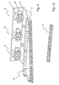
- the elongate light entry surface has Lichteinkoppelfacetten 28 and faces the Lichteinkoppelmodulen.
- Under an elongated light exit surface is understood in this application, a light exit surface which is at least five times as long as wide.
- Each Lichteinkoppelmodul has Auskoppelfacetten 30.
- the light coupling module is set up by its material properties such as transparency and refractive index in conjunction with its geometry to illuminate its coupling facets from the inside with homogeneous and focused around a preferred direction light of the light source.
- the coupling-out facets are arranged in a ring shape.
- the Auskoppelfacetten are set up by their shape and arrangement in Lichteinkoppelmodul to incident on them To couple out light 32 of the light source and to direct this decoupled light 34 on the Lichteinkoppelfacetten 28 of the transparent luminous body.
- the decoupling facets are furthermore configured to concentrate light 34, which has been decoupled via a decoupling facet, onto precisely one light coupling facet 28 of the transparent filament.
- the Lichteinkoppelfacetten the transparent filament are adapted to couple incident light 34 and to direct this coupled light 36 to a portion of the light exit surface 24 of the transparent filament 22.
- This coupled-in light 36 emerges from the transparent luminous element 22 via the elongated light exit surface 24. Since the invention causes a largely homogeneous illumination of the elongated light exit surface 24 with light bundles which have a small opening angle, which can also be zero (parallel light), it is easily possible, with molded into the light exit surface 24 pads or rollers 38 a rule-compliant signal light distribution to produce, in the example An angle width of + - 20 ° in the horizontal and + - 10 ° in the vertical must be illuminated with prescribed brightness values.
- the angle data refer to angle deviations to a straight line, which is parallel to the vehicle longitudinal axis at a proper use of the lamp in the motor vehicle, passes through the lamp and coincides with the main emission of the lamp.
- the main emission direction is the direction in which the brightness maximum is achieved.
- the z-direction is eg parallel to the vehicle transverse axis, and the y-direction is parallel to the vehicle's vertical axis.
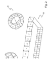
- FIG. 1 in particular also shows an embodiment with a strongly curved transparent luminous element 22.
- the transparent luminous element is curved in particular around the main light propagation direction of the light propagating in it. At the subject of FIG. 1 this is the z direction.
- a Lichteinkoppelfacette 38 of the transparent luminous body which is located in a curved portion of the transparent filament
- a Auskoppelfacette 40 of the annular Lichteinkoppelmoduls 16 is assigned, which is located in a region of the Lichteinkoppelmoduls, which is curved in the same direction ,
- the assignment is in each case given by the light bundle which connects the respective coupling-off facet 40 to the respective Lichteinkoppelfacette 38 by starting from the respective Auskoppelfacette 40 and illuminates the respective Lichteinkoppelfacette 38.
- FIG. 1 shows in particular an arrangement of a transparent filament 22 and separate light input modules 16, 18, 20.
- Each Lichteinkoppelmodul has a number of Auskoppelfacetten that are generally different from each other.
- the transparent luminous element 22 has different Lichteinkoppelfacetten on its narrow and elongated back, which serves as a light entry surface 26, wherein preferably each Lichteinkoppelfacette the transparent filament in a one to one - assignment to a Auskoppelfacette a Lichteinkoppelmoduls is aligned and vice versa.
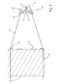
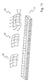
- FIG. 2 illustrates such an assignment of coupling-out facets 1, 2, 3, 4, 5, 6, 7, 8, a light-coupling module 20 and light-coupling facets 1 ', 2', 3 ', 4', 5 ', 6', 7 ', 8'. , a transparent filament 22 by pairs of equal numbers.
- the light beam emanating from the coupling-out facet 1 is concentrated on the light-coupling facet 1 '.
- An analog one-to-one mapping results for the other pairs of numbers.
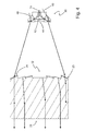
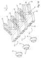
- FIG. 3 shows a plan view of a section through a transparent filament and a Lichteinkoppelmodul in a plane in which the light propagates between the Lichteinkoppelmodul and the transparent filament.
- the light coupling module 20 is here a transparent solid having a refractive index greater than one. It has a light entry surface 40. Densely (distance less than 1 mm) in front of the light entrance surface 40, a half-space radiator is arranged as the light source 14.
- the half-space radiator is preferably a semiconductor light source, for example a light-emitting diode. A light beam emanating from the light source 14 enters the light input module 20 via the light entry surface 40. Due to the refraction, the opening angle of the light beam is reduced.
- Half space radiators which have an approximately rotationally symmetrical emission characteristic are preferred here.
- a first central deflector 42 deflects the light of the light source by total internal internal reflection radially outward around.
- the shape of the deflector 42 results, for example, by rotation of a parabola branch around an axis of rotation 44 which coincides with the main emission direction of the light source 14.
- the light source is preferably arranged in the focal point of this parabola branch, wherein this focal point, since it is in air and thus in a medium with refractive index other than the refractive index of Lichteinkoppelmoduls 20, located at a different location, as if the light only in a single medium would spread.
- the light propagates after deflection at the first central deflector 42 in planes parallel to each other which are perpendicular to the main radiation direction and axis of rotation, and also propagates radially outward in each such plane.
- a second deflector 46 is arranged and configured in the light path of the radially outwardly propagating light such that it deflects the incident light parallel to the main emission direction of the light source.
- the second deflector 46 is e.g. realized as a conical surface which extends around the main emission direction at a fixed distance and with the main emission direction forms an angle of 45 °, which opens in the main emission direction.
- the purpose of the second deflector 46 is to produce a light bundle bundled around the main emission direction of the semiconductor light source as a preferential direction.
- the second deflector is composed of individual facets. It is essential in any case that the second deflector generates a largely concentrated light 32.
- This collimated light 32 falls on the inside Auskoppelfacetten 30 a.
- the coupling-out facets 30 are just arranged so that they are illuminated by the collimated light.
- the individual output coupling facets 30 are tilted relative to each other in such a way that they just break the exiting light such that this light 34 is focused precisely on the associated Lichteinkoppelfacette 28 of the transparent filament and illuminate them as homogeneously as possible.
- the individual Lichteinkoppelfacetten 28 of the transparent filament 22 direct the coupled light on the light exit surface 24 of the transparent filament.
- the Lichteinkoppelfacetten 28 are preferably adapted to direct the individual, coupled via them light bundles in a common direction, so as bundles that are parallel to each other, to the light exit surface. Said direction is preferably parallel to the narrow side edges 48 of the transparent luminous body, which lie between the light entry surface and the light exit surface of the transparent filament.
- the light exit surface 24 in one embodiment has molded cushion and / or roll optics.
- the light exit surface 24 is smooth.
- a further preferred embodiment provides a cushion disk in the light path behind the light exit surface. Under a cushion disc is understood here a lens, are formed in the light-refracting pad and / or rollers in the light entry surface or light exit surface of the lens. It is also preferred that the light exit surface 24 is stepped, wherein it may have, depending on the embodiment, smooth or molded cushion containing stages.
- FIG. 3 shows in particular an arrangement of a transparent filament 22 and a separate Lichteinkoppelmodul 20.
- Each Lichteinkoppelmodul has a number of Auskoppelfacetten, which are mutually different in general.
- the transparent luminous element 22 has different Lichteinkoppelfacetten 28 at its narrow and elongated back, preferably each Lichteinkoppelfacette 28 of the transparent filament 22 is aligned in a one-to-one assignment to a Auskoppelfacette 30 of a Lichteinkoppelmoduls 20 and vice versa.
- FIG. 4 shows the subject of the FIG. 3 with a modified geometry of the light exit surface, which here has a curvature about an axis perpendicular to Hauptlichtausbreitungsraum axis.
- FIG. 3 also for them FIG. 4 .
- structures molded into the light exit surface such as cylindrical optics or concave or convex cushion optics
- Such structures can also be formed in at least one, but possibly also several or even all Lichteinkoppelfacetten.
- the previously presented embodiments have Lichteinkoppelmodule in which the Auskoppelfacetten a single Lichteinkoppelmoduls are arranged in the form of a closed loop, in particular a circular loop here.
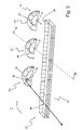
- FIG. 5 shows a perspective view of a further embodiment in which the Auskoppelfacetten 30 are arranged by a Lichteinkoppelmodul not in a closed loop, but in an open loop, in particular a section of a circle, in particular in a semicircle or an even smaller section of a circle ,
- the elongate light entry surface 26 has Lichteinkoppelfacetten.
- Under an elongated light exit surface is also understood here a light exit surface which is at least five times as long as wide.
- Each Lichteinkoppelmodul 50, 52, 54 has Auskoppelfacetten 30.
- Each Lichteinkoppelmodul is set up by its material properties such as transparency and refractive index in conjunction with its geometry to illuminate its Auskoppelfacetten 30 from the inside with a homogeneous and focused around a preferred direction around light 32 of the light source.
- the decoupling facets 30 are each arranged in a semicircular manner by a light coupling module.
- the Auskoppelfacetten are by their shape and arrangement in the Lichteinkoppelmodul adapted to decouple incident light 32 of the light source and to direct this decoupled light 34 on the Lichteinkoppelfacetten 28 of the transparent filament.
- the decoupling facets are furthermore configured to concentrate light 34, which is decoupled via a decoupling facet, onto precisely one light coupling facet 28 of the transparent luminous element 22.
- the Lichteinkoppelfacetten 28 of the transparent filament are adapted to couple incident light 34 and to direct this coupled light 36 to a portion of the light exit surface of the transparent filament.
- FIG. 6 shows a cross section through the arrangement according to the FIG. 5 ,
- the cross-section is in the directions indicated in the figure x, y, and z parallel to a yz plane.
- the main light emission direction 56 therefore lies in the sectional plane, and the sectional plane lies transversely to the longitudinal extent of the light exit surface 24 of the transparent luminous element 22.
- the light coupling module 52 is here also a transparent solid with a refractive index greater than one. It has a light entry side 58.
- a difference to the Lichteinkoppelmodul, which in the FIG. 4 is shown results from the position of the light entrance side.
- the light entrance side is a rear side facing away from the Auskoppelfacetten Lichteinkoppelmoduls.
- the axis of rotation of the Lichteinkoppelmoduls according to the FIG. 4 is perpendicular to this back.
- the light entrance side 58 in the light coupling module 52 which in the FIG. 5 is shown, a side in which the axis of rotation of the Lichteinkoppelmoduls according to the FIG. 6 is, or a side that is at least parallel to this axis of rotation.
- the light source 12 which is preferably a half-space radiator, in particular a semiconductor light source such as a light-emitting diode, is arranged so that its main radiation direction is aligned radially to the circular segment-shaped light coupling module 52.
- the light entry side 58 has a central recess 60 which has a central bottom region 62 with a convex lens cross-section in the plane of the drawing and side walls 64 adjoining it.
- the overall shape of the central recess 60 results from the rotation of the cross-section about the axis of rotation 44 shown in the plane of the drawing and bounded by the lens and the side walls.
- the light coupling module is delimited on its light entry side by two curved surfaces 66, 68, which appear as convex curved lines in the plane of the drawing. These surfaces are preferably curved in such a way that light from the light source 12, which has entered the light coupling module 52 via the side walls 64 of the recess and which is incident on these surfaces 66, 68 from the inside, is focused in the plane of the drawing or aligned in parallel. This is achieved, for example, by producing the shape of the surfaces by rotating the convex curved lines about the rotation axis 44, and that the convexly curved lines 64, 66 are branches of a parabola, at the focal point of which the light source 12 is arranged. Due to the refraction when light enters the light coupling module, this focus will deviate slightly from the geometric focus of the parabola branches, which will be compensated for by the person skilled in the art, however can.
- the lens of the central bottom portion 62 is preferably curved so that light of the light source 12, which has entered via the central lens surface of the recess in the Lichteinkoppelmodul, is aligned in parallel in the plane of the drawing. The light then propagates in the light coupling module as it is in the Lichteinkoppelmodul according to the FIGS. 1 to 4 spreads behind the first deflector used there.
- the lens surface and the parabolic branch-shaped limited surfaces thus represent an example of a first deflector.
- a second deflector 46 is arranged and configured in the light path of the radially outwardly propagating light such that it deflects the incident light transversely to the main emission direction of the light source 12.
- the second deflector 46 is e.g. realized as a conical surface which extends around the main emission direction at a fixed distance and with the main emission direction forms an angle of 45 °, which opens in the main emission direction.
- the purpose of the second deflector 46 is also to produce a light bundle that is bundled around the main emission direction of the semiconductor light source as a preferred direction.
- the second deflector is composed of individual facets. It is essential in any case that the second deflector as far as possible bundled light generated.
- the decoupling facets are arranged so that they are illuminated by the collimated light.
- the individual decoupling facets 30 are tilted relative to one another in such a way that they just break the exiting light in such a way that this light is concentrated precisely on the associated Lichteinkoppelfacette 28 of the transparent filament and this illuminates as homogeneously as possible.
- the decoupling facets 28 are set up to direct light coupled into the light coupling module onto the light exit surface of the transparent luminous body.
- the coupling-out facets of the light-coupling modules are set up to concentrate light 34, which was decoupled via a coupling-out facet, onto exactly one light coupling surface of the transparent luminous body.
- the Lichteinkoppelfacetten the transparent solid are adapted to couple incident light 34 and to direct this coupled light 36 to a portion of the light exit surface 24 of the transparent filament 22.
- the coupling-in facets 28 are preferably designed to direct the individual light bundles coupled in via them in a common direction, ie as bundles which are parallel to one another, onto the light exit surface. Said direction is preferably parallel to the narrow side edges of the transparent luminous body, between the light entry surface and the light exit surface of the transparent filament lie.
- FIG. 7 shows an embodiment based on the embodiment of the FIG. 6 based.
- two Lichteinkoppelmodule 70, 72 arranged along its axis of rotation 44 one behind the other.
- the second light coupling module 72 which is farther from the transparent light guide body 22, is so much larger in the radial direction than the first light coupling module 70 closer to the transparent light guide body 22 in this arrangement that the second light coupling module 72 passes the first light coupling module 70 on the first light coupling module the same Einkoppelfacetten 1 ', 2', 3 ', 4', and so on of the transparent filament 22 radiates as the first Lichteinkoppelmodul 70 and the same cushions and / or rollers in the light exit surface 24 of the transparent filament 22 illuminated.
- the light sources of the first Lichteinkoppelmodule and second Lichteinkoppelmodule in this sense are preferably different and preferably differ in their light color. It is preferred that the light sources of the first Lichteinkoppelmodule produce white light and the light sources of the second light sources preferably produce yellow light, or vice versa. With the white light, a daytime running light function and, with dimmed light sources, a limiting light function can be realized. With the yellow light, a flashing light function can be realized. Thus, three different light functions can be realized separately from one another at the light exit surface of the transparent filament.
- An alternative is to use light sources with the same light color for the first light coupling modules and the second light coupling modules to produce a correspondingly larger luminous flux of uniform light color.
- FIG. 7 moreover shows a beam path 74 of light of a smaller light coupling module and a beam path 76 of light of a larger light coupling module of a pair of light coupling modules arranged behind one another.
- FIG. 8 shows the appearance of the arrangement of the FIG. 6 or FIG. 7 in an on state from one of the main emission direction opposite viewing direction.
- the elongated shape of the light exit surface of the transparent filament forms.
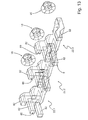
- FIG. 9 shows an arrangement of a transparent filament together with three Lichteinkoppelmodulen with boards and heat sink.
- Each light coupling module has fastening devices 89 for attachment to a circuit board 81 and / or the heat sink.
- the luminous body preferably also has devices for its attachment.
- the Lichteinkoppelmodule 16, 18, 20 are preferably aligned relative to the transparent luminous element 22, for which on the heat sink 78 adjustment devices can be present.
- each Lichteinkoppelmodul is individually adjustable.
- a further embodiment provides that diaphragms are still mounted between the light input modules and the luminous element or that the light coupling modules are accommodated in a separate housing in order to largely conceal the light coupling modules for a viewer.
- FIG. 9 shows additional, pattern-shaped decoupling structures 82, which are arranged on a different from the light entrance side and a light exit side top and / or bottom of the transparent luminous body 22 to modify the appearance by styling effects.
- decoupling structures merely represent optional elements of preferred embodiments.
- FIG. 10 shows an embodiment of a filament as a narrow lens 84.
- This diffuser can be used in all configurations. It differs from the previously described transparent luminous element 22 substantially in that, in the direction of the extension of the axes of rotation of the light coupling modules, it has a constant thickness in the light propagation direction apart from surface modulations. This thickness is preferably 2 mm to 5 mm.
- Your the Lichteinkoppelmodulen facing the light entrance side is just as faceted as it is the case with the luminaries of the other figures. This applies analogously for molded pillows and / or roller on the light entrance side and / or light exit side.
- FIG. 11 shows an embodiment in which the Lichteinkoppelmodule be realized as a concave mirror reflectors 86, 88, 90.
- transparent solids as Einkoppetti have the advantage that can easily achieve a uniform distribution of the luminous flux on the different, serving for coupling facets by the described deflectors.
- this can be achieved by facets 1 2, 3, 4, 5, 6, 7, 8 with facet-to-facet variable geometry.
- the reflector surface is divided into individual facets, which each receive an equal or at least similar large luminous flux from the light source.
- the light-coupling module is set up to illuminate the coupling-out facets with light of the light source that is homogeneous and focused around a preferred direction.
- the distribution of the coupling-out facets of the light-coupling modules depends on the emission characteristic of the LED, which as a rule is a Lambert radiator.
- the coupling-out facets can be arranged regularly, such as e.g. in the modules 20.
- the modules 52 have the profile of a catadioptric optical attachment which is rotated about an axis parallel to the light emission direction of the lamp. In that case, the semicircle must be divided so that similar amounts of light fall in each sector. This is also the case with the modules 52 and this can be seen in the figures - eg in Figure 7 ,
- the facet 1 has a larger angular extent in the semicircle than the facet 2.
- the emission characteristic of the LED is preferably taken into account in the design of the coupling-out facets.
- a division into mutually equal angular ranges is not optimal, because the LED emits more light than Lambert radiator in the direction perpendicular to the emitter surface direction than under large radiation angles (eg at 75 °) to this vertical direction.
- the solid angle range covered by the coupling-off facets is smaller for centrally arranged facets as with arranged in the edge areas facets.
- the most general procedure for designing homogeneously illuminated coupling-out facets is to subdivide the emitted light of the light source into regions with the same or similar luminous flux, taking into account the geometry of the light coupling module, and to project this subdivision onto the light exit surface of the light coupling modules. This can be greatly simplified if appropriate symmetries are used.
- the orientation of the Auskoppelfacetten the Lichteinkoppelmodule and the orientation of Lichteinkoppelfacetten the transparent filament can be done with known methods of optical beam calculation.
- it When assigning the facets, it must be ensured that the inclination of the facets and thus the deflection angles of the beams in the totality are kept as small as possible. This is already shown in the figures.
- FIG. 12 shows a further embodiment, which is based on the objects of FIGS. 1 to 4 and differs in the design of the transparent luminous body of these objects.
- the value of n is preferably between 2 and 10, respectively.
- the value of m is preferably between 1 and 5, respectively.
- modules formed from in each case m light input modules and the respectively associated partial luminous body can in principle be arranged arbitrarily and independently of one another. In particular, as shown, they can be arranged next to one another in a row in the direction of the longitudinal extent of their light exit surfaces. But they can also be arranged in a row one above the other and / or laterally offset or offset in a plane to each other, they can also be arranged on a curved line and have the same or different main emission directions.
- the light exit surface of a partial luminous body is divided into separate partial surfaces 80, wherein each partial surface forms the end of a Lichtleitfingers 82, which merges with its other, its partial surface end remote into the rest of the partial luminous body.
- the partial surfaces are preferably at least partially not in the same plane with each other and / or the remaining partial luminous body, from which they lead out like fingers of a hand.
- the partial luminous body on a first deflection which deflects the light from the surface, and it has a second deflection surface 86, which then deflects the deflected light to the light exit surface.
- the FIG. 13 shows the subject of the FIG. 12 from a directed to the light exit surfaces viewing direction.
- the deflection surfaces result, so to speak, in that the transparent luminous body has kinks which bound the deflection surfaces.
- Such kinks and thus deflection surfaces can be combined with any of the embodiments presented here.
- the light emitting diodes with the associated circuit board and the one or more heat sinks can be covered by a diaphragm, while the light exit surface is not covered by the diaphragm.
Landscapes
- Engineering & Computer Science (AREA)
- General Engineering & Computer Science (AREA)
- Physics & Mathematics (AREA)
- Microelectronics & Electronic Packaging (AREA)
- Optics & Photonics (AREA)
- Non-Portable Lighting Devices Or Systems Thereof (AREA)
Applications Claiming Priority (1)
| Application Number | Priority Date | Filing Date | Title |
|---|---|---|---|
| DE102014218991.8A DE102014218991A1 (de) | 2014-09-22 | 2014-09-22 | Leuchte für ein Kraftfahrzeug |
Publications (2)
| Publication Number | Publication Date |
|---|---|
| EP3012521A1 true EP3012521A1 (fr) | 2016-04-27 |
| EP3012521B1 EP3012521B1 (fr) | 2018-02-21 |
Family
ID=54065243
Family Applications (1)
| Application Number | Title | Priority Date | Filing Date |
|---|---|---|---|
| EP15183957.8A Active EP3012521B1 (fr) | 2014-09-22 | 2015-09-04 | Éclairage pour un vehicule automobile |
Country Status (2)
| Country | Link |
|---|---|
| EP (1) | EP3012521B1 (fr) |
| DE (1) | DE102014218991A1 (fr) |
Families Citing this family (9)
| Publication number | Priority date | Publication date | Assignee | Title |
|---|---|---|---|---|
| IT201600114529A1 (it) * | 2016-11-14 | 2018-05-14 | Automotive Lighting Italia Spa | Fanale automobilistico |
| IT201600114519A1 (it) * | 2016-11-14 | 2018-05-14 | Automotive Lighting Italia Spa | Fanale automobilistico |
| DE102017105838A1 (de) * | 2017-03-17 | 2018-09-20 | Automotive Lighting Reutlingen Gmbh | Beleuchtungseinrichtung eines Kraftfahrzeugs mit einer Lichtleiteranordnung |
| DE102017106441A1 (de) * | 2017-03-24 | 2018-09-27 | Automotive Lighting Reutlingen Gmbh | Kraftfahrzeugleuchte mit einem flächigen Lichtleiter |
| DE102017112805A1 (de) | 2017-06-09 | 2018-12-13 | Automotive Lighting Reutlingen Gmbh | Transparente Bauteilanordnung eines Leuchtenmoduls und Leuchtenmodul mit einer solchen transparenten Bauteilanordnung |
| DE102018202325A1 (de) * | 2018-02-15 | 2019-08-22 | Volkswagen Aktiengesellschaft | Beleuchtungsvorrichtung zur Erzeugung von wenigstens zwei Lichtfunktionen mit einem streifen- oder linienartigen Lichterscheinungsbild |
| DE102020128556A1 (de) * | 2020-10-30 | 2022-05-05 | Bayerische Motoren Werke Aktiengesellschaft | Beleuchtungsvorrichtung für ein Kraftfahrzeug |
| DE102021111324A1 (de) | 2021-05-03 | 2022-11-03 | Marelli Automotive Lighting Reutlingen (Germany) GmbH | Multifunktionale Beleuchtungseinrichtung mit einer Lichtscheibe |
| EP4257872A1 (fr) * | 2022-04-05 | 2023-10-11 | ZKW Group GmbH | Dispositif optique pour phare automobile |
Citations (7)
| Publication number | Priority date | Publication date | Assignee | Title |
|---|---|---|---|---|
| DE19925363A1 (de) | 1999-06-02 | 2000-12-07 | Hella Kg Hueck & Co | Vorrichtung zum gezielten Abgeben oder Einleiten von Licht in einen Lichtleiter |
| US20130021815A1 (en) * | 2011-07-20 | 2013-01-24 | Koito Manufacturing Co., Ltd. | Vehicular Lamp |
| EP2587120A1 (fr) * | 2011-10-27 | 2013-05-01 | odelo GmbH | Conduit de lumière et véhicule automobile muni d'un tel conduit de lumière |
| US20140071703A1 (en) * | 2012-09-13 | 2014-03-13 | Koito Manufacturing Co., Ltd. | Vehicular lamp |
| DE102012112076A1 (de) * | 2012-12-11 | 2014-06-12 | Hella Kgaa Hueck & Co. | Beleuchtungsvorrichtung für Fahrzeuge |
| DE102014100058A1 (de) * | 2013-01-08 | 2014-07-10 | Ford Global Technologies, Llc | Hocheffiziente kleinprofilfahrzeug-led-module und scheinwerfer |
| DE102013100557A1 (de) * | 2013-01-21 | 2014-07-24 | Hella Kgaa Hueck & Co. | Beleuchtungsvorrichtung für Fahrzeuge |
Family Cites Families (5)
| Publication number | Priority date | Publication date | Assignee | Title |
|---|---|---|---|---|
| US5931576A (en) * | 1996-02-26 | 1999-08-03 | North American Lighting, Inc. | Optical coupler for distributive lighting system |
| US20090207610A1 (en) * | 2008-02-19 | 2009-08-20 | Edwin Mitchell Sayers | Combination rear lighting system |
| DE102010018119B4 (de) * | 2010-04-24 | 2023-06-22 | HELLA GmbH & Co. KGaA | Optikelement für eine Beleuchtungseinrichtung eines Fahrzeugs |
| US8434892B2 (en) * | 2011-03-30 | 2013-05-07 | Varroccorp Holding Bv | Collimator assembly |
| DE102011002281A1 (de) * | 2011-04-27 | 2012-10-31 | Hella Kgaa Hueck & Co. | Leuchte für Fahrzeuge |
-
2014
- 2014-09-22 DE DE102014218991.8A patent/DE102014218991A1/de not_active Ceased
-
2015
- 2015-09-04 EP EP15183957.8A patent/EP3012521B1/fr active Active
Patent Citations (7)
| Publication number | Priority date | Publication date | Assignee | Title |
|---|---|---|---|---|
| DE19925363A1 (de) | 1999-06-02 | 2000-12-07 | Hella Kg Hueck & Co | Vorrichtung zum gezielten Abgeben oder Einleiten von Licht in einen Lichtleiter |
| US20130021815A1 (en) * | 2011-07-20 | 2013-01-24 | Koito Manufacturing Co., Ltd. | Vehicular Lamp |
| EP2587120A1 (fr) * | 2011-10-27 | 2013-05-01 | odelo GmbH | Conduit de lumière et véhicule automobile muni d'un tel conduit de lumière |
| US20140071703A1 (en) * | 2012-09-13 | 2014-03-13 | Koito Manufacturing Co., Ltd. | Vehicular lamp |
| DE102012112076A1 (de) * | 2012-12-11 | 2014-06-12 | Hella Kgaa Hueck & Co. | Beleuchtungsvorrichtung für Fahrzeuge |
| DE102014100058A1 (de) * | 2013-01-08 | 2014-07-10 | Ford Global Technologies, Llc | Hocheffiziente kleinprofilfahrzeug-led-module und scheinwerfer |
| DE102013100557A1 (de) * | 2013-01-21 | 2014-07-24 | Hella Kgaa Hueck & Co. | Beleuchtungsvorrichtung für Fahrzeuge |
Also Published As
| Publication number | Publication date |
|---|---|
| DE102014218991A1 (de) | 2016-03-24 |
| EP3012521B1 (fr) | 2018-02-21 |
Similar Documents
| Publication | Publication Date | Title |
|---|---|---|
| EP3012521B1 (fr) | Éclairage pour un vehicule automobile | |
| EP2607774B1 (fr) | Dispositif d'éclairage d'un véhicule automobile avec une surface lumineuse longue et plane | |
| DE102013212353B4 (de) | Kraftfahrzeugbeleuchtungseinrichtung mit einer eine Einkoppeloptik und eine Transport- und Umformoptik aufweisenden Lichtleiteranordnung | |
| EP2360427B1 (fr) | Réflecteur tri-zone | |
| EP2984397B1 (fr) | Unité d'éclairage pour projecteur de véhicule | |
| EP2618045A1 (fr) | Dispositif dýéclairage pour un véhicule automobile | |
| DE102014004472B4 (de) | Leuchtmodul aufweisend ein optisches Element | |
| DE102008056049B4 (de) | Licht emittierende Vorrichtung umfassend mindestens eine Leuchtdiode und Beleuchtungseinrichtung für ein Kraftfahrzeug umfassend eine solche Vorrichtung | |
| EP2927572A1 (fr) | Lampe de véhicule automobile avec effet d'essuyage | |
| EP3121510B1 (fr) | Optique rapportee | |
| DE102010013045A1 (de) | Fahrzeugleuchte mit einer Lichtleiter-Vorsatzoptik | |
| EP2472177A2 (fr) | Eclairage | |
| DE102017106441A1 (de) | Kraftfahrzeugleuchte mit einem flächigen Lichtleiter | |
| DE69833421T2 (de) | Lichtabgabeoptik für Fahrzeugsignalleuchten | |
| WO2016166203A1 (fr) | Système optique et ensemble d'émission de lumière | |
| EP3086025A1 (fr) | Unite de rayonnement pour une lampe chirurgicale | |
| DE102007038205B4 (de) | Leuchte mit Lichtleiterplatte | |
| DE102006013654B4 (de) | Scheinwerfer | |
| DE102013206850A1 (de) | Zur Erzeugung einer Signal-Lichtverteilung eingerichtetes Lichtmodul einer Kraftfahrzeugbeleuchtungseinrichtung | |
| EP3719391B1 (fr) | Module de feu de route partiel pour un phare de véhicule automobile | |
| DE102018113151B4 (de) | Leuchtenmodul für eine Kraftfahrzeugleuchte | |
| DE202017100585U1 (de) | Beleuchtungseinrichtung eines Kraftfahrzeugs | |
| DE102016120903A1 (de) | Beleuchtungseinrichtung eines Kraftfahrzeugs | |
| DE202016104672U1 (de) | Kraftfahrzeugleuchte mit einem linienförmige Facetten aufweisenden Reflektor | |
| DE102015219346A1 (de) | Lichtmodul für eine Kraftfahrzeugbeleuchtungseinrichtung |
Legal Events
| Date | Code | Title | Description |
|---|---|---|---|
| PUAI | Public reference made under article 153(3) epc to a published international application that has entered the european phase |
Free format text: ORIGINAL CODE: 0009012 |
|
| AK | Designated contracting states |
Kind code of ref document: A1 Designated state(s): AL AT BE BG CH CY CZ DE DK EE ES FI FR GB GR HR HU IE IS IT LI LT LU LV MC MK MT NL NO PL PT RO RS SE SI SK SM TR |
|
| AX | Request for extension of the european patent |
Extension state: BA ME |
|
| 17P | Request for examination filed |
Effective date: 20161013 |
|
| RBV | Designated contracting states (corrected) |
Designated state(s): AL AT BE BG CH CY CZ DE DK EE ES FI FR GB GR HR HU IE IS IT LI LT LU LV MC MK MT NL NO PL PT RO RS SE SI SK SM TR |
|
| GRAP | Despatch of communication of intention to grant a patent |
Free format text: ORIGINAL CODE: EPIDOSNIGR1 |
|
| INTG | Intention to grant announced |
Effective date: 20171004 |
|
| GRAS | Grant fee paid |
Free format text: ORIGINAL CODE: EPIDOSNIGR3 |
|
| GRAA | (expected) grant |
Free format text: ORIGINAL CODE: 0009210 |
|
| AK | Designated contracting states |
Kind code of ref document: B1 Designated state(s): AL AT BE BG CH CY CZ DE DK EE ES FI FR GB GR HR HU IE IS IT LI LT LU LV MC MK MT NL NO PL PT RO RS SE SI SK SM TR |
|
| REG | Reference to a national code |
Ref country code: GB Ref legal event code: FG4D Free format text: NOT ENGLISH |
|
| REG | Reference to a national code |
Ref country code: CH Ref legal event code: EP |
|
| REG | Reference to a national code |
Ref country code: AT Ref legal event code: REF Ref document number: 972144 Country of ref document: AT Kind code of ref document: T Effective date: 20180315 |
|
| REG | Reference to a national code |
Ref country code: IE Ref legal event code: FG4D Free format text: LANGUAGE OF EP DOCUMENT: GERMAN |
|
| REG | Reference to a national code |
Ref country code: DE Ref legal event code: R096 Ref document number: 502015003135 Country of ref document: DE |
|
| REG | Reference to a national code |
Ref country code: NL Ref legal event code: MP Effective date: 20180221 |
|
| REG | Reference to a national code |
Ref country code: LT Ref legal event code: MG4D |
|
| PG25 | Lapsed in a contracting state [announced via postgrant information from national office to epo] |
Ref country code: CY Free format text: LAPSE BECAUSE OF FAILURE TO SUBMIT A TRANSLATION OF THE DESCRIPTION OR TO PAY THE FEE WITHIN THE PRESCRIBED TIME-LIMIT Effective date: 20180221 Ref country code: HR Free format text: LAPSE BECAUSE OF FAILURE TO SUBMIT A TRANSLATION OF THE DESCRIPTION OR TO PAY THE FEE WITHIN THE PRESCRIBED TIME-LIMIT Effective date: 20180221 Ref country code: NL Free format text: LAPSE BECAUSE OF FAILURE TO SUBMIT A TRANSLATION OF THE DESCRIPTION OR TO PAY THE FEE WITHIN THE PRESCRIBED TIME-LIMIT Effective date: 20180221 Ref country code: LT Free format text: LAPSE BECAUSE OF FAILURE TO SUBMIT A TRANSLATION OF THE DESCRIPTION OR TO PAY THE FEE WITHIN THE PRESCRIBED TIME-LIMIT Effective date: 20180221 Ref country code: ES Free format text: LAPSE BECAUSE OF FAILURE TO SUBMIT A TRANSLATION OF THE DESCRIPTION OR TO PAY THE FEE WITHIN THE PRESCRIBED TIME-LIMIT Effective date: 20180221 Ref country code: FI Free format text: LAPSE BECAUSE OF FAILURE TO SUBMIT A TRANSLATION OF THE DESCRIPTION OR TO PAY THE FEE WITHIN THE PRESCRIBED TIME-LIMIT Effective date: 20180221 Ref country code: NO Free format text: LAPSE BECAUSE OF FAILURE TO SUBMIT A TRANSLATION OF THE DESCRIPTION OR TO PAY THE FEE WITHIN THE PRESCRIBED TIME-LIMIT Effective date: 20180521 |
|
| REG | Reference to a national code |
Ref country code: FR Ref legal event code: PLFP Year of fee payment: 4 |
|
| PG25 | Lapsed in a contracting state [announced via postgrant information from national office to epo] |
Ref country code: BG Free format text: LAPSE BECAUSE OF FAILURE TO SUBMIT A TRANSLATION OF THE DESCRIPTION OR TO PAY THE FEE WITHIN THE PRESCRIBED TIME-LIMIT Effective date: 20180521 Ref country code: SE Free format text: LAPSE BECAUSE OF FAILURE TO SUBMIT A TRANSLATION OF THE DESCRIPTION OR TO PAY THE FEE WITHIN THE PRESCRIBED TIME-LIMIT Effective date: 20180221 Ref country code: LV Free format text: LAPSE BECAUSE OF FAILURE TO SUBMIT A TRANSLATION OF THE DESCRIPTION OR TO PAY THE FEE WITHIN THE PRESCRIBED TIME-LIMIT Effective date: 20180221 Ref country code: RS Free format text: LAPSE BECAUSE OF FAILURE TO SUBMIT A TRANSLATION OF THE DESCRIPTION OR TO PAY THE FEE WITHIN THE PRESCRIBED TIME-LIMIT Effective date: 20180221 Ref country code: GR Free format text: LAPSE BECAUSE OF FAILURE TO SUBMIT A TRANSLATION OF THE DESCRIPTION OR TO PAY THE FEE WITHIN THE PRESCRIBED TIME-LIMIT Effective date: 20180522 |
|
| PG25 | Lapsed in a contracting state [announced via postgrant information from national office to epo] |
Ref country code: MT Free format text: LAPSE BECAUSE OF FAILURE TO SUBMIT A TRANSLATION OF THE DESCRIPTION OR TO PAY THE FEE WITHIN THE PRESCRIBED TIME-LIMIT Effective date: 20180221 |
|
| PG25 | Lapsed in a contracting state [announced via postgrant information from national office to epo] |
Ref country code: PL Free format text: LAPSE BECAUSE OF FAILURE TO SUBMIT A TRANSLATION OF THE DESCRIPTION OR TO PAY THE FEE WITHIN THE PRESCRIBED TIME-LIMIT Effective date: 20180221 Ref country code: EE Free format text: LAPSE BECAUSE OF FAILURE TO SUBMIT A TRANSLATION OF THE DESCRIPTION OR TO PAY THE FEE WITHIN THE PRESCRIBED TIME-LIMIT Effective date: 20180221 Ref country code: RO Free format text: LAPSE BECAUSE OF FAILURE TO SUBMIT A TRANSLATION OF THE DESCRIPTION OR TO PAY THE FEE WITHIN THE PRESCRIBED TIME-LIMIT Effective date: 20180221 Ref country code: AL Free format text: LAPSE BECAUSE OF FAILURE TO SUBMIT A TRANSLATION OF THE DESCRIPTION OR TO PAY THE FEE WITHIN THE PRESCRIBED TIME-LIMIT Effective date: 20180221 Ref country code: IT Free format text: LAPSE BECAUSE OF FAILURE TO SUBMIT A TRANSLATION OF THE DESCRIPTION OR TO PAY THE FEE WITHIN THE PRESCRIBED TIME-LIMIT Effective date: 20180221 |
|
| REG | Reference to a national code |
Ref country code: DE Ref legal event code: R097 Ref document number: 502015003135 Country of ref document: DE |
|
| PG25 | Lapsed in a contracting state [announced via postgrant information from national office to epo] |
Ref country code: SM Free format text: LAPSE BECAUSE OF FAILURE TO SUBMIT A TRANSLATION OF THE DESCRIPTION OR TO PAY THE FEE WITHIN THE PRESCRIBED TIME-LIMIT Effective date: 20180221 Ref country code: DK Free format text: LAPSE BECAUSE OF FAILURE TO SUBMIT A TRANSLATION OF THE DESCRIPTION OR TO PAY THE FEE WITHIN THE PRESCRIBED TIME-LIMIT Effective date: 20180221 Ref country code: SK Free format text: LAPSE BECAUSE OF FAILURE TO SUBMIT A TRANSLATION OF THE DESCRIPTION OR TO PAY THE FEE WITHIN THE PRESCRIBED TIME-LIMIT Effective date: 20180221 Ref country code: CZ Free format text: LAPSE BECAUSE OF FAILURE TO SUBMIT A TRANSLATION OF THE DESCRIPTION OR TO PAY THE FEE WITHIN THE PRESCRIBED TIME-LIMIT Effective date: 20180221 |
|
| PLBE | No opposition filed within time limit |
Free format text: ORIGINAL CODE: 0009261 |
|
| STAA | Information on the status of an ep patent application or granted ep patent |
Free format text: STATUS: NO OPPOSITION FILED WITHIN TIME LIMIT |
|
| RIC2 | Information provided on ipc code assigned after grant |
Ipc: F21S 8/10 20181130AFI20160321BHEP |
|
| REG | Reference to a national code |
Ref country code: CH Ref legal event code: PK Free format text: BERICHTIGUNGEN |
|
| 26N | No opposition filed |
Effective date: 20181122 |
|
| REG | Reference to a national code |
Ref country code: CH Ref legal event code: PK Free format text: BERICHTIGUNGEN |
|
| RIC2 | Information provided on ipc code assigned after grant |
Ipc: F21S 8/10 20060101AFI20160321BHEP |
|
| PG25 | Lapsed in a contracting state [announced via postgrant information from national office to epo] |
Ref country code: SI Free format text: LAPSE BECAUSE OF FAILURE TO SUBMIT A TRANSLATION OF THE DESCRIPTION OR TO PAY THE FEE WITHIN THE PRESCRIBED TIME-LIMIT Effective date: 20180221 |
|
| PG25 | Lapsed in a contracting state [announced via postgrant information from national office to epo] |
Ref country code: MC Free format text: LAPSE BECAUSE OF FAILURE TO SUBMIT A TRANSLATION OF THE DESCRIPTION OR TO PAY THE FEE WITHIN THE PRESCRIBED TIME-LIMIT Effective date: 20180221 |
|
| REG | Reference to a national code |
Ref country code: CH Ref legal event code: PL |
|
| REG | Reference to a national code |
Ref country code: BE Ref legal event code: MM Effective date: 20180930 |
|
| REG | Reference to a national code |
Ref country code: IE Ref legal event code: MM4A |
|
| PG25 | Lapsed in a contracting state [announced via postgrant information from national office to epo] |
Ref country code: LU Free format text: LAPSE BECAUSE OF NON-PAYMENT OF DUE FEES Effective date: 20180904 |
|
| PG25 | Lapsed in a contracting state [announced via postgrant information from national office to epo] |
Ref country code: IE Free format text: LAPSE BECAUSE OF NON-PAYMENT OF DUE FEES Effective date: 20180904 |
|
| PG25 | Lapsed in a contracting state [announced via postgrant information from national office to epo] |
Ref country code: LI Free format text: LAPSE BECAUSE OF NON-PAYMENT OF DUE FEES Effective date: 20180930 Ref country code: CH Free format text: LAPSE BECAUSE OF NON-PAYMENT OF DUE FEES Effective date: 20180930 Ref country code: BE Free format text: LAPSE BECAUSE OF NON-PAYMENT OF DUE FEES Effective date: 20180930 |
|
| PG25 | Lapsed in a contracting state [announced via postgrant information from national office to epo] |
Ref country code: TR Free format text: LAPSE BECAUSE OF FAILURE TO SUBMIT A TRANSLATION OF THE DESCRIPTION OR TO PAY THE FEE WITHIN THE PRESCRIBED TIME-LIMIT Effective date: 20180221 |
|
| PG25 | Lapsed in a contracting state [announced via postgrant information from national office to epo] |
Ref country code: PT Free format text: LAPSE BECAUSE OF FAILURE TO SUBMIT A TRANSLATION OF THE DESCRIPTION OR TO PAY THE FEE WITHIN THE PRESCRIBED TIME-LIMIT Effective date: 20180221 |
|
| PG25 | Lapsed in a contracting state [announced via postgrant information from national office to epo] |
Ref country code: MK Free format text: LAPSE BECAUSE OF NON-PAYMENT OF DUE FEES Effective date: 20180221 Ref country code: HU Free format text: LAPSE BECAUSE OF FAILURE TO SUBMIT A TRANSLATION OF THE DESCRIPTION OR TO PAY THE FEE WITHIN THE PRESCRIBED TIME-LIMIT; INVALID AB INITIO Effective date: 20150904 |
|
| PG25 | Lapsed in a contracting state [announced via postgrant information from national office to epo] |
Ref country code: IS Free format text: LAPSE BECAUSE OF FAILURE TO SUBMIT A TRANSLATION OF THE DESCRIPTION OR TO PAY THE FEE WITHIN THE PRESCRIBED TIME-LIMIT Effective date: 20180621 |
|
| GBPC | Gb: european patent ceased through non-payment of renewal fee |
Effective date: 20190904 |
|
| PG25 | Lapsed in a contracting state [announced via postgrant information from national office to epo] |
Ref country code: GB Free format text: LAPSE BECAUSE OF NON-PAYMENT OF DUE FEES Effective date: 20190904 |
|
| REG | Reference to a national code |
Ref country code: AT Ref legal event code: MM01 Ref document number: 972144 Country of ref document: AT Kind code of ref document: T Effective date: 20200904 |
|
| PG25 | Lapsed in a contracting state [announced via postgrant information from national office to epo] |
Ref country code: AT Free format text: LAPSE BECAUSE OF NON-PAYMENT OF DUE FEES Effective date: 20200904 |
|
| P01 | Opt-out of the competence of the unified patent court (upc) registered |
Effective date: 20230508 |
|
| PGFP | Annual fee paid to national office [announced via postgrant information from national office to epo] |
Ref country code: FR Payment date: 20230822 Year of fee payment: 9 Ref country code: DE Payment date: 20230822 Year of fee payment: 9 |