EP3012301A1 - Revêtement de dispositif médical lubrifié avec un nombre réduit de particules - Google Patents
Revêtement de dispositif médical lubrifié avec un nombre réduit de particules Download PDFInfo
- Publication number
- EP3012301A1 EP3012301A1 EP15198514.0A EP15198514A EP3012301A1 EP 3012301 A1 EP3012301 A1 EP 3012301A1 EP 15198514 A EP15198514 A EP 15198514A EP 3012301 A1 EP3012301 A1 EP 3012301A1
- Authority
- EP
- European Patent Office
- Prior art keywords
- layer
- coating
- cross
- linking agent
- substrate
- Prior art date
- Legal status (The legal status is an assumption and is not a legal conclusion. Google has not performed a legal analysis and makes no representation as to the accuracy of the status listed.)
- Granted
Links
- 238000000576 coating method Methods 0.000 title claims abstract description 218
- 239000011248 coating agent Substances 0.000 title claims abstract description 203
- 239000003431 cross linking reagent Substances 0.000 claims abstract description 103
- 229920000036 polyvinylpyrrolidone Polymers 0.000 claims abstract description 70
- 235000013855 polyvinylpyrrolidone Nutrition 0.000 claims abstract description 54
- 239000001267 polyvinylpyrrolidone Substances 0.000 claims abstract description 54
- 229920000642 polymer Polymers 0.000 claims abstract description 47
- 229920002401 polyacrylamide Polymers 0.000 claims abstract description 26
- 239000000758 substrate Substances 0.000 claims description 107
- 238000000034 method Methods 0.000 claims description 49
- XLYOFNOQVPJJNP-UHFFFAOYSA-N water Substances O XLYOFNOQVPJJNP-UHFFFAOYSA-N 0.000 claims description 36
- 238000012360 testing method Methods 0.000 claims description 35
- 239000002904 solvent Substances 0.000 claims description 29
- 238000003618 dip coating Methods 0.000 claims description 20
- 230000005855 radiation Effects 0.000 claims description 14
- 150000003839 salts Chemical class 0.000 claims description 13
- 229910052751 metal Inorganic materials 0.000 claims description 9
- 239000002184 metal Substances 0.000 claims description 9
- PXHVJJICTQNCMI-UHFFFAOYSA-N Nickel Chemical compound [Ni] PXHVJJICTQNCMI-UHFFFAOYSA-N 0.000 claims description 6
- 150000002739 metals Chemical class 0.000 claims description 6
- BASFCYQUMIYNBI-UHFFFAOYSA-N platinum Chemical compound [Pt] BASFCYQUMIYNBI-UHFFFAOYSA-N 0.000 claims description 6
- 229910045601 alloy Inorganic materials 0.000 claims description 5
- 239000000956 alloy Substances 0.000 claims description 5
- 238000001035 drying Methods 0.000 claims description 5
- 230000001747 exhibiting effect Effects 0.000 claims description 5
- FQPSGWSUVKBHSU-UHFFFAOYSA-N methacrylamide Chemical compound CC(=C)C(N)=O FQPSGWSUVKBHSU-UHFFFAOYSA-N 0.000 claims description 5
- BAPJBEWLBFYGME-UHFFFAOYSA-N Methyl acrylate Chemical compound COC(=O)C=C BAPJBEWLBFYGME-UHFFFAOYSA-N 0.000 claims description 4
- KDLHZDBZIXYQEI-UHFFFAOYSA-N Palladium Chemical compound [Pd] KDLHZDBZIXYQEI-UHFFFAOYSA-N 0.000 claims description 4
- RTAQQCXQSZGOHL-UHFFFAOYSA-N Titanium Chemical compound [Ti] RTAQQCXQSZGOHL-UHFFFAOYSA-N 0.000 claims description 3
- NIXOWILDQLNWCW-UHFFFAOYSA-N acrylic acid group Chemical group C(C=C)(=O)O NIXOWILDQLNWCW-UHFFFAOYSA-N 0.000 claims description 3
- WRUAHXANJKHFIL-UHFFFAOYSA-N benzene-1,3-disulfonic acid Chemical compound OS(=O)(=O)C1=CC=CC(S(O)(=O)=O)=C1 WRUAHXANJKHFIL-UHFFFAOYSA-N 0.000 claims description 3
- 229910052759 nickel Inorganic materials 0.000 claims description 3
- 125000001273 sulfonato group Chemical group [O-]S(*)(=O)=O 0.000 claims description 3
- 229910052719 titanium Inorganic materials 0.000 claims description 3
- 239000010936 titanium Substances 0.000 claims description 3
- 229920002818 (Hydroxyethyl)methacrylate Polymers 0.000 claims description 2
- QRIMLDXJAPZHJE-UHFFFAOYSA-N 2,3-dihydroxypropyl 2-methylprop-2-enoate Chemical compound CC(=C)C(=O)OCC(O)CO QRIMLDXJAPZHJE-UHFFFAOYSA-N 0.000 claims description 2
- OWPUOLBODXJOKH-UHFFFAOYSA-N 2,3-dihydroxypropyl prop-2-enoate Chemical compound OCC(O)COC(=O)C=C OWPUOLBODXJOKH-UHFFFAOYSA-N 0.000 claims description 2
- SMZOUWXMTYCWNB-UHFFFAOYSA-N 2-(2-methoxy-5-methylphenyl)ethanamine Chemical compound COC1=CC=C(C)C=C1CCN SMZOUWXMTYCWNB-UHFFFAOYSA-N 0.000 claims description 2
- OMIGHNLMNHATMP-UHFFFAOYSA-N 2-hydroxyethyl prop-2-enoate Chemical compound OCCOC(=O)C=C OMIGHNLMNHATMP-UHFFFAOYSA-N 0.000 claims description 2
- HRPVXLWXLXDGHG-UHFFFAOYSA-N Acrylamide Chemical compound NC(=O)C=C HRPVXLWXLXDGHG-UHFFFAOYSA-N 0.000 claims description 2
- WOBHKFSMXKNTIM-UHFFFAOYSA-N Hydroxyethyl methacrylate Chemical compound CC(=C)C(=O)OCCO WOBHKFSMXKNTIM-UHFFFAOYSA-N 0.000 claims description 2
- CERQOIWHTDAKMF-UHFFFAOYSA-N Methacrylic acid Chemical compound CC(=C)C(O)=O CERQOIWHTDAKMF-UHFFFAOYSA-N 0.000 claims description 2
- VVQNEPGJFQJSBK-UHFFFAOYSA-N Methyl methacrylate Chemical compound COC(=O)C(C)=C VVQNEPGJFQJSBK-UHFFFAOYSA-N 0.000 claims description 2
- KJTLSVCANCCWHF-UHFFFAOYSA-N Ruthenium Chemical compound [Ru] KJTLSVCANCCWHF-UHFFFAOYSA-N 0.000 claims description 2
- PCHJSUWPFVWCPO-UHFFFAOYSA-N gold Chemical compound [Au] PCHJSUWPFVWCPO-UHFFFAOYSA-N 0.000 claims description 2
- 229910052737 gold Inorganic materials 0.000 claims description 2
- 239000010931 gold Substances 0.000 claims description 2
- 229910052763 palladium Inorganic materials 0.000 claims description 2
- 229910052697 platinum Inorganic materials 0.000 claims description 2
- 229910052702 rhenium Inorganic materials 0.000 claims description 2
- WUAPFZMCVAUBPE-UHFFFAOYSA-N rhenium atom Chemical compound [Re] WUAPFZMCVAUBPE-UHFFFAOYSA-N 0.000 claims description 2
- 229910052703 rhodium Inorganic materials 0.000 claims description 2
- 239000010948 rhodium Substances 0.000 claims description 2
- MHOVAHRLVXNVSD-UHFFFAOYSA-N rhodium atom Chemical compound [Rh] MHOVAHRLVXNVSD-UHFFFAOYSA-N 0.000 claims description 2
- 229910052707 ruthenium Inorganic materials 0.000 claims description 2
- WFKWXMTUELFFGS-UHFFFAOYSA-N tungsten Chemical compound [W] WFKWXMTUELFFGS-UHFFFAOYSA-N 0.000 claims description 2
- 229910052721 tungsten Inorganic materials 0.000 claims description 2
- 239000010937 tungsten Substances 0.000 claims description 2
- 229920000058 polyacrylate Polymers 0.000 claims 1
- 239000010410 layer Substances 0.000 description 160
- 239000000243 solution Substances 0.000 description 130
- KFZMGEQAYNKOFK-UHFFFAOYSA-N Isopropanol Chemical compound CC(C)O KFZMGEQAYNKOFK-UHFFFAOYSA-N 0.000 description 114
- -1 aryl ketone Chemical class 0.000 description 27
- 229920002614 Polyether block amide Polymers 0.000 description 23
- 239000002585 base Substances 0.000 description 18
- 150000001875 compounds Chemical class 0.000 description 17
- 229910001507 metal halide Inorganic materials 0.000 description 14
- 150000005309 metal halides Chemical class 0.000 description 14
- 239000003795 chemical substances by application Substances 0.000 description 13
- 238000006467 substitution reaction Methods 0.000 description 12
- 238000002156 mixing Methods 0.000 description 11
- 239000002245 particle Substances 0.000 description 11
- 229920001223 polyethylene glycol Polymers 0.000 description 11
- 238000012956 testing procedure Methods 0.000 description 10
- 125000000217 alkyl group Chemical group 0.000 description 9
- 125000003118 aryl group Chemical group 0.000 description 9
- RWCCWEUUXYIKHB-UHFFFAOYSA-N benzophenone Chemical compound C=1C=CC=CC=1C(=O)C1=CC=CC=C1 RWCCWEUUXYIKHB-UHFFFAOYSA-N 0.000 description 8
- 239000012965 benzophenone Substances 0.000 description 8
- 125000005647 linker group Chemical group 0.000 description 8
- 229910052760 oxygen Inorganic materials 0.000 description 8
- MNYJUJNPCUQHCP-UHFFFAOYSA-M sodium;bis(4-benzoylphenyl) phosphate Chemical compound [Na+].C=1C=C(C(=O)C=2C=CC=CC=2)C=CC=1OP(=O)([O-])OC(C=C1)=CC=C1C(=O)C1=CC=CC=C1 MNYJUJNPCUQHCP-UHFFFAOYSA-M 0.000 description 8
- 230000000694 effects Effects 0.000 description 7
- 229920001903 high density polyethylene Polymers 0.000 description 7
- 239000004700 high-density polyethylene Substances 0.000 description 7
- 239000000203 mixture Substances 0.000 description 7
- 229910052717 sulfur Inorganic materials 0.000 description 7
- 230000008961 swelling Effects 0.000 description 7
- CSCPPACGZOOCGX-UHFFFAOYSA-N Acetone Chemical compound CC(C)=O CSCPPACGZOOCGX-UHFFFAOYSA-N 0.000 description 6
- KWOLFJPFCHCOCG-UHFFFAOYSA-N Acetophenone Chemical compound CC(=O)C1=CC=CC=C1 KWOLFJPFCHCOCG-UHFFFAOYSA-N 0.000 description 6
- 239000004696 Poly ether ether ketone Substances 0.000 description 6
- HEMHJVSKTPXQMS-UHFFFAOYSA-M Sodium hydroxide Chemical compound [OH-].[Na+] HEMHJVSKTPXQMS-UHFFFAOYSA-M 0.000 description 6
- 239000003153 chemical reaction reagent Substances 0.000 description 6
- 239000000463 material Substances 0.000 description 6
- 229920002530 polyetherether ketone Polymers 0.000 description 6
- QGZKDVFQNNGYKY-UHFFFAOYSA-O Ammonium Chemical compound [NH4+] QGZKDVFQNNGYKY-UHFFFAOYSA-O 0.000 description 5
- 239000004952 Polyamide Substances 0.000 description 5
- RYULULVJWLRDQH-UHFFFAOYSA-N [4-(bromomethyl)phenyl]-phenylmethanone Chemical compound C1=CC(CBr)=CC=C1C(=O)C1=CC=CC=C1 RYULULVJWLRDQH-UHFFFAOYSA-N 0.000 description 5
- 125000000623 heterocyclic group Chemical group 0.000 description 5
- 230000004048 modification Effects 0.000 description 5
- 238000012986 modification Methods 0.000 description 5
- 229910052757 nitrogen Inorganic materials 0.000 description 5
- 229920002647 polyamide Polymers 0.000 description 5
- 239000004814 polyurethane Substances 0.000 description 5
- 229920002635 polyurethane Polymers 0.000 description 5
- AZQWKYJCGOJGHM-UHFFFAOYSA-N 1,4-benzoquinone Chemical compound O=C1C=CC(=O)C=C1 AZQWKYJCGOJGHM-UHFFFAOYSA-N 0.000 description 4
- XHZPRMZZQOIPDS-UHFFFAOYSA-N 2-Methyl-2-[(1-oxo-2-propenyl)amino]-1-propanesulfonic acid Chemical compound OS(=O)(=O)CC(C)(C)NC(=O)C=C XHZPRMZZQOIPDS-UHFFFAOYSA-N 0.000 description 4
- 239000004971 Cross linker Substances 0.000 description 4
- 229920003082 Povidone K 90 Polymers 0.000 description 4
- 230000002378 acidificating effect Effects 0.000 description 4
- 125000002947 alkylene group Chemical group 0.000 description 4
- 125000000129 anionic group Chemical group 0.000 description 4
- 230000015572 biosynthetic process Effects 0.000 description 4
- 239000011247 coating layer Substances 0.000 description 4
- 229940079593 drug Drugs 0.000 description 4
- 239000003814 drug Substances 0.000 description 4
- 239000011521 glass Substances 0.000 description 4
- 239000007943 implant Substances 0.000 description 4
- 150000002500 ions Chemical class 0.000 description 4
- 229910052711 selenium Inorganic materials 0.000 description 4
- 239000000126 substance Substances 0.000 description 4
- UHOVQNZJYSORNB-UHFFFAOYSA-N Benzene Chemical compound C1=CC=CC=C1 UHOVQNZJYSORNB-UHFFFAOYSA-N 0.000 description 3
- IAZDPXIOMUYVGZ-UHFFFAOYSA-N Dimethylsulphoxide Chemical compound CS(C)=O IAZDPXIOMUYVGZ-UHFFFAOYSA-N 0.000 description 3
- 229920000299 Nylon 12 Polymers 0.000 description 3
- 208000008883 Patent Foramen Ovale Diseases 0.000 description 3
- 239000004698 Polyethylene Substances 0.000 description 3
- 239000002202 Polyethylene glycol Substances 0.000 description 3
- 208000001910 Ventricular Heart Septal Defects Diseases 0.000 description 3
- RJGDLRCDCYRQOQ-UHFFFAOYSA-N anthrone Chemical compound C1=CC=C2C(=O)C3=CC=CC=C3CC2=C1 RJGDLRCDCYRQOQ-UHFFFAOYSA-N 0.000 description 3
- 125000002091 cationic group Chemical group 0.000 description 3
- 239000008199 coating composition Substances 0.000 description 3
- PXRIWVPUWQJAHG-UHFFFAOYSA-L disodium;4,5-bis[(4-benzoylphenyl)methoxy]benzene-1,3-disulfonate Chemical group [Na+].[Na+].C=1C=C(C(=O)C=2C=CC=CC=2)C=CC=1COC=1C(S([O-])(=O)=O)=CC(S(=O)(=O)[O-])=CC=1OCC(C=C1)=CC=C1C(=O)C1=CC=CC=C1 PXRIWVPUWQJAHG-UHFFFAOYSA-L 0.000 description 3
- 150000004820 halides Chemical class 0.000 description 3
- 125000005842 heteroatom Chemical group 0.000 description 3
- 229920001427 mPEG Polymers 0.000 description 3
- 229920000573 polyethylene Polymers 0.000 description 3
- 230000008439 repair process Effects 0.000 description 3
- 239000007787 solid Substances 0.000 description 3
- 230000002792 vascular Effects 0.000 description 3
- 201000003130 ventricular septal defect Diseases 0.000 description 3
- IJBXHSUZEBBJJG-UHFFFAOYSA-N (4-benzoylphenyl)methyl-[2-[(4-benzoylphenyl)methyl-dimethylazaniumyl]ethyl]-dimethylazanium Chemical class C=1C=C(C(=O)C=2C=CC=CC=2)C=CC=1C[N+](C)(C)CC[N+](C)(C)CC(C=C1)=CC=C1C(=O)C1=CC=CC=C1 IJBXHSUZEBBJJG-UHFFFAOYSA-N 0.000 description 2
- DKBZZUNCOFCQFT-UHFFFAOYSA-L (4-benzoylphenyl)methyl-[2-[(4-benzoylphenyl)methyl-dimethylazaniumyl]ethyl]-dimethylazanium;dibromide Chemical group [Br-].[Br-].C=1C=C(C(=O)C=2C=CC=CC=2)C=CC=1C[N+](C)(C)CC[N+](C)(C)CC(C=C1)=CC=C1C(=O)C1=CC=CC=C1 DKBZZUNCOFCQFT-UHFFFAOYSA-L 0.000 description 2
- LSNNMFCWUKXFEE-UHFFFAOYSA-M Bisulfite Chemical compound OS([O-])=O LSNNMFCWUKXFEE-UHFFFAOYSA-M 0.000 description 2
- ZOXJGFHDIHLPTG-UHFFFAOYSA-N Boron Chemical compound [B] ZOXJGFHDIHLPTG-UHFFFAOYSA-N 0.000 description 2
- 0 CC1*CCC1 Chemical compound CC1*CCC1 0.000 description 2
- 239000004215 Carbon black (E152) Substances 0.000 description 2
- JHWNWJKBPDFINM-UHFFFAOYSA-N Laurolactam Chemical compound O=C1CCCCCCCCCCCN1 JHWNWJKBPDFINM-UHFFFAOYSA-N 0.000 description 2
- 239000004642 Polyimide Substances 0.000 description 2
- PPBRXRYQALVLMV-UHFFFAOYSA-N Styrene Chemical compound C=CC1=CC=CC=C1 PPBRXRYQALVLMV-UHFFFAOYSA-N 0.000 description 2
- XNOMWKDAQZCFGK-UHFFFAOYSA-N [4-[(4-benzoylphenyl)methoxymethyl]phenyl]-phenylmethanone Chemical compound C=1C=C(COCC=2C=CC(=CC=2)C(=O)C=2C=CC=CC=2)C=CC=1C(=O)C1=CC=CC=C1 XNOMWKDAQZCFGK-UHFFFAOYSA-N 0.000 description 2
- 230000004913 activation Effects 0.000 description 2
- PYKYMHQGRFAEBM-UHFFFAOYSA-N anthraquinone Natural products CCC(=O)c1c(O)c2C(=O)C3C(C=CC=C3O)C(=O)c2cc1CC(=O)OC PYKYMHQGRFAEBM-UHFFFAOYSA-N 0.000 description 2
- 150000004056 anthraquinones Chemical class 0.000 description 2
- 238000013459 approach Methods 0.000 description 2
- 239000007864 aqueous solution Substances 0.000 description 2
- 150000001540 azides Chemical class 0.000 description 2
- 229910052796 boron Inorganic materials 0.000 description 2
- 150000007942 carboxylates Chemical class 0.000 description 2
- 230000000747 cardiac effect Effects 0.000 description 2
- 239000000919 ceramic Substances 0.000 description 2
- 210000001175 cerebrospinal fluid Anatomy 0.000 description 2
- 238000009675 coating thickness measurement Methods 0.000 description 2
- 238000001816 cooling Methods 0.000 description 2
- 229920001577 copolymer Polymers 0.000 description 2
- 150000004845 diazirines Chemical class 0.000 description 2
- 230000005284 excitation Effects 0.000 description 2
- 238000001125 extrusion Methods 0.000 description 2
- 230000005283 ground state Effects 0.000 description 2
- 229930195733 hydrocarbon Natural products 0.000 description 2
- 150000002430 hydrocarbons Chemical class 0.000 description 2
- 229910052739 hydrogen Inorganic materials 0.000 description 2
- 239000001257 hydrogen Substances 0.000 description 2
- 125000004435 hydrogen atom Chemical group [H]* 0.000 description 2
- 208000015181 infectious disease Diseases 0.000 description 2
- 238000001802 infusion Methods 0.000 description 2
- 150000002576 ketones Chemical class 0.000 description 2
- 238000012538 light obscuration Methods 0.000 description 2
- 230000000926 neurological effect Effects 0.000 description 2
- 230000000399 orthopedic effect Effects 0.000 description 2
- NFHFRUOZVGFOOS-UHFFFAOYSA-N palladium;triphenylphosphane Chemical group [Pd].C1=CC=CC=C1P(C=1C=CC=CC=1)C1=CC=CC=C1.C1=CC=CC=C1P(C=1C=CC=CC=1)C1=CC=CC=C1.C1=CC=CC=C1P(C=1C=CC=CC=1)C1=CC=CC=C1.C1=CC=CC=C1P(C=1C=CC=CC=1)C1=CC=CC=C1 NFHFRUOZVGFOOS-UHFFFAOYSA-N 0.000 description 2
- 239000013618 particulate matter Substances 0.000 description 2
- WXZMFSXDPGVJKK-UHFFFAOYSA-N pentaerythritol Chemical compound OCC(CO)(CO)CO WXZMFSXDPGVJKK-UHFFFAOYSA-N 0.000 description 2
- 125000004437 phosphorous atom Chemical group 0.000 description 2
- 229910052698 phosphorus Inorganic materials 0.000 description 2
- CPGRMGOILBSUQC-UHFFFAOYSA-N phosphoryl azide Chemical class [N-]=[N+]=NP(=O)(N=[N+]=[N-])N=[N+]=[N-] CPGRMGOILBSUQC-UHFFFAOYSA-N 0.000 description 2
- 229920000515 polycarbonate Polymers 0.000 description 2
- 239000004417 polycarbonate Substances 0.000 description 2
- 229920000728 polyester Polymers 0.000 description 2
- 229920001721 polyimide Polymers 0.000 description 2
- 229910052700 potassium Inorganic materials 0.000 description 2
- 239000000047 product Substances 0.000 description 2
- 238000000746 purification Methods 0.000 description 2
- 230000007420 reactivation Effects 0.000 description 2
- 238000001953 recrystallisation Methods 0.000 description 2
- 238000010992 reflux Methods 0.000 description 2
- 229910052710 silicon Inorganic materials 0.000 description 2
- 239000010703 silicon Substances 0.000 description 2
- 125000006850 spacer group Chemical group 0.000 description 2
- 210000001519 tissue Anatomy 0.000 description 2
- AXVOAMVQOCBPQT-UHFFFAOYSA-N triphos Chemical compound C=1C=CC=CC=1P(C=1C=CC=CC=1)CCP(C=1C=CC=CC=1)CCP(C=1C=CC=CC=1)C1=CC=CC=C1 AXVOAMVQOCBPQT-UHFFFAOYSA-N 0.000 description 2
- 125000000391 vinyl group Chemical group [H]C([*])=C([H])[H] 0.000 description 2
- 229920002554 vinyl polymer Polymers 0.000 description 2
- JNELGWHKGNBSMD-UHFFFAOYSA-N xanthone Chemical compound C1=CC=C2C(=O)C3=CC=CC=C3OC2=C1 JNELGWHKGNBSMD-UHFFFAOYSA-N 0.000 description 2
- 229910052727 yttrium Inorganic materials 0.000 description 2
- PGOQAHNIFXPYQR-UHFFFAOYSA-N (4-benzoylphenyl)methyl-[6-[(4-benzoylphenyl)methyl-dimethylazaniumyl]hexyl]-dimethylazanium Chemical class C=1C=C(C(=O)C=2C=CC=CC=2)C=CC=1C[N+](C)(C)CCCCCC[N+](C)(C)CC(C=C1)=CC=C1C(=O)C1=CC=CC=C1 PGOQAHNIFXPYQR-UHFFFAOYSA-N 0.000 description 1
- BQCIDUSAKPWEOX-UHFFFAOYSA-N 1,1-Difluoroethene Chemical compound FC(F)=C BQCIDUSAKPWEOX-UHFFFAOYSA-N 0.000 description 1
- PGRNEGLBSNLPNP-UHFFFAOYSA-N 1,6-dichloro-3-methylhex-1-ene Chemical compound ClC=CC(C)CCCCl PGRNEGLBSNLPNP-UHFFFAOYSA-N 0.000 description 1
- UUORGSXWPOMXJJ-UHFFFAOYSA-N 1-[azido(ethyl)phosphoryl]ethane Chemical compound CCP(=O)(CC)N=[N+]=[N-] UUORGSXWPOMXJJ-UHFFFAOYSA-N 0.000 description 1
- JMVZUADCGPOVDM-UHFFFAOYSA-N 2-[2-(4-benzoylphenyl)ethyl-[2-[(4-benzoylphenyl)methyl-dimethylazaniumyl]ethyl]amino]ethyl-[(4-benzoylphenyl)methyl]-dimethylazanium Chemical class C=1C=C(C(=O)C=2C=CC=CC=2)C=CC=1C[N+](C)(C)CCN(CC[N+](C)(C)CC=1C=CC(=CC=1)C(=O)C=1C=CC=CC=1)CCC(C=C1)=CC=C1C(=O)C1=CC=CC=C1 JMVZUADCGPOVDM-UHFFFAOYSA-N 0.000 description 1
- RWDSKJNFYUOSRD-UHFFFAOYSA-N 2-[2-(4-benzoylphenyl)ethyl-[2-[2-(4-benzoylphenyl)ethyl-[2-[(4-benzoylphenyl)methyl-dimethylazaniumyl]ethyl]amino]ethyl]amino]ethyl-[(4-benzoylphenyl)methyl]-dimethylazanium Chemical class C=1C=C(C(=O)C=2C=CC=CC=2)C=CC=1C[N+](C)(C)CCN(CCC=1C=CC(=CC=1)C(=O)C=1C=CC=CC=1)CCN(CC[N+](C)(C)CC=1C=CC(=CC=1)C(=O)C=1C=CC=CC=1)CCC(C=C1)=CC=C1C(=O)C1=CC=CC=C1 RWDSKJNFYUOSRD-UHFFFAOYSA-N 0.000 description 1
- NRTABCXMDFHEGK-UHFFFAOYSA-N 2-[bis[2-[(4-benzoylphenyl)methoxy]ethyl]amino]ethanesulfonic acid Chemical compound C=1C=C(C(=O)C=2C=CC=CC=2)C=CC=1COCCN(CCS(=O)(=O)O)CCOCC(C=C1)=CC=C1C(=O)C1=CC=CC=C1 NRTABCXMDFHEGK-UHFFFAOYSA-N 0.000 description 1
- HQNSWBRZIOYGAW-UHFFFAOYSA-N 2-chloro-n,n-dimethylpyridin-4-amine Chemical compound CN(C)C1=CC=NC(Cl)=C1 HQNSWBRZIOYGAW-UHFFFAOYSA-N 0.000 description 1
- QFYSZYAVKZUZCM-UHFFFAOYSA-N 2-diazonio-1,1,1-trifluorohex-2-en-3-olate Chemical compound CCCC(=O)C(=[N+]=[N-])C(F)(F)F QFYSZYAVKZUZCM-UHFFFAOYSA-N 0.000 description 1
- JBVSBLLOZVDAAZ-UHFFFAOYSA-N 2-diazonio-1-[(2-methylpropan-2-yl)oxy]ethenolate Chemical compound CC(C)(C)OC([O-])=C[N+]#N JBVSBLLOZVDAAZ-UHFFFAOYSA-N 0.000 description 1
- UWBALSPTLHOGFE-UHFFFAOYSA-N 2-diazonio-1-phenoxyethenolate Chemical compound [N-]=[N+]=CC(=O)OC1=CC=CC=C1 UWBALSPTLHOGFE-UHFFFAOYSA-N 0.000 description 1
- ZSTBZBURMWJKSQ-UHFFFAOYSA-N 2-diazonio-1-phenylethenolate Chemical compound N#[N+]C=C([O-])C1=CC=CC=C1 ZSTBZBURMWJKSQ-UHFFFAOYSA-N 0.000 description 1
- QENRKQYUEGJNNZ-UHFFFAOYSA-N 2-methyl-1-(prop-2-enoylamino)propane-1-sulfonic acid Chemical group CC(C)C(S(O)(=O)=O)NC(=O)C=C QENRKQYUEGJNNZ-UHFFFAOYSA-N 0.000 description 1
- IXEVBKYJNFWMPR-UHFFFAOYSA-N 3-phenyl-3-(trifluoromethyl)diazirine Chemical compound C=1C=CC=CC=1C1(C(F)(F)F)N=N1 IXEVBKYJNFWMPR-UHFFFAOYSA-N 0.000 description 1
- VCTBSHQJICJJFV-UHFFFAOYSA-N 4-azido-1-fluoro-2-nitrobenzene Chemical compound [O-][N+](=O)C1=CC(N=[N+]=[N-])=CC=C1F VCTBSHQJICJJFV-UHFFFAOYSA-N 0.000 description 1
- RTUYNYSPUHQITK-UHFFFAOYSA-N 4-methylbenzoyl azide Chemical compound CC1=CC=C(C(=O)N=[N+]=[N-])C=C1 RTUYNYSPUHQITK-UHFFFAOYSA-N 0.000 description 1
- GDALETGZDYOOGB-UHFFFAOYSA-N Acridone Natural products C1=C(O)C=C2N(C)C3=CC=CC=C3C(=O)C2=C1O GDALETGZDYOOGB-UHFFFAOYSA-N 0.000 description 1
- 206010002329 Aneurysm Diseases 0.000 description 1
- 229940122361 Bisphosphonate Drugs 0.000 description 1
- BTBUEUYNUDRHOZ-UHFFFAOYSA-N Borate Chemical compound [O-]B([O-])[O-] BTBUEUYNUDRHOZ-UHFFFAOYSA-N 0.000 description 1
- KXDHJXZQYSOELW-UHFFFAOYSA-M Carbamate Chemical compound NC([O-])=O KXDHJXZQYSOELW-UHFFFAOYSA-M 0.000 description 1
- OKTJSMMVPCPJKN-UHFFFAOYSA-N Carbon Chemical compound [C] OKTJSMMVPCPJKN-UHFFFAOYSA-N 0.000 description 1
- 229910000684 Cobalt-chrome Inorganic materials 0.000 description 1
- YXHKONLOYHBTNS-UHFFFAOYSA-N Diazomethane Chemical compound C=[N+]=[N-] YXHKONLOYHBTNS-UHFFFAOYSA-N 0.000 description 1
- LFQSCWFLJHTTHZ-UHFFFAOYSA-N Ethanol Chemical compound CCO LFQSCWFLJHTTHZ-UHFFFAOYSA-N 0.000 description 1
- 208000010412 Glaucoma Diseases 0.000 description 1
- WQZGKKKJIJFFOK-GASJEMHNSA-N Glucose Natural products OC[C@H]1OC(O)[C@H](O)[C@@H](O)[C@@H]1O WQZGKKKJIJFFOK-GASJEMHNSA-N 0.000 description 1
- 206010019909 Hernia Diseases 0.000 description 1
- UFHFLCQGNIYNRP-UHFFFAOYSA-N Hydrogen Chemical compound [H][H] UFHFLCQGNIYNRP-UHFFFAOYSA-N 0.000 description 1
- DGAQECJNVWCQMB-PUAWFVPOSA-M Ilexoside XXIX Chemical compound C[C@@H]1CC[C@@]2(CC[C@@]3(C(=CC[C@H]4[C@]3(CC[C@@H]5[C@@]4(CC[C@@H](C5(C)C)OS(=O)(=O)[O-])C)C)[C@@H]2[C@]1(C)O)C)C(=O)O[C@H]6[C@@H]([C@H]([C@@H]([C@H](O6)CO)O)O)O.[Na+] DGAQECJNVWCQMB-PUAWFVPOSA-M 0.000 description 1
- 229910000575 Ir alloy Inorganic materials 0.000 description 1
- WHXSMMKQMYFTQS-UHFFFAOYSA-N Lithium Chemical compound [Li] WHXSMMKQMYFTQS-UHFFFAOYSA-N 0.000 description 1
- WHNWPMSKXPGLAX-UHFFFAOYSA-N N-Vinyl-2-pyrrolidone Chemical compound C=CN1CCCC1=O WHNWPMSKXPGLAX-UHFFFAOYSA-N 0.000 description 1
- 229920002292 Nylon 6 Polymers 0.000 description 1
- 229920002302 Nylon 6,6 Polymers 0.000 description 1
- BXEFQPCKQSTMKA-UHFFFAOYSA-N OC(=O)C=[N+]=[N-] Chemical class OC(=O)C=[N+]=[N-] BXEFQPCKQSTMKA-UHFFFAOYSA-N 0.000 description 1
- XGISLELTRMFJOC-UHFFFAOYSA-N OCC(CO)(CO)CO.C=1C=C(COCC(COCC=2C=CC(=CC=2)C(=O)C=2C=CC=CC=2)(COCC=2C=CC(=CC=2)C(=O)C=2C=CC=CC=2)COCC=2C=CC(=CC=2)C(=O)C=2C=CC=CC=2)C=CC=1C(=O)C1=CC=CC=C1 Chemical compound OCC(CO)(CO)CO.C=1C=C(COCC(COCC=2C=CC(=CC=2)C(=O)C=2C=CC=CC=2)(COCC=2C=CC(=CC=2)C(=O)C=2C=CC=CC=2)COCC=2C=CC(=CC=2)C(=O)C=2C=CC=CC=2)C=CC=1C(=O)C1=CC=CC=C1 XGISLELTRMFJOC-UHFFFAOYSA-N 0.000 description 1
- PNQKWMXGTJCYPD-UHFFFAOYSA-N P(=O)(O)(O)O.C(C1=CC=CC=C1)(=O)C1=CC=CC=C1.C(C1=CC=CC=C1)(=O)C1=CC=CC=C1.C(C1=CC=CC=C1)(=O)C1=CC=CC=C1 Chemical compound P(=O)(O)(O)O.C(C1=CC=CC=C1)(=O)C1=CC=CC=C1.C(C1=CC=CC=C1)(=O)C1=CC=CC=C1.C(C1=CC=CC=C1)(=O)C1=CC=CC=C1 PNQKWMXGTJCYPD-UHFFFAOYSA-N 0.000 description 1
- 229910019142 PO4 Inorganic materials 0.000 description 1
- ZLMJMSJWJFRBEC-UHFFFAOYSA-N Potassium Chemical compound [K] ZLMJMSJWJFRBEC-UHFFFAOYSA-N 0.000 description 1
- 229910001260 Pt alloy Inorganic materials 0.000 description 1
- FAPWRFPIFSIZLT-UHFFFAOYSA-M Sodium chloride Chemical compound [Na+].[Cl-] FAPWRFPIFSIZLT-UHFFFAOYSA-M 0.000 description 1
- PJANXHGTPQOBST-VAWYXSNFSA-N Stilbene Natural products C=1C=CC=CC=1/C=C/C1=CC=CC=C1 PJANXHGTPQOBST-VAWYXSNFSA-N 0.000 description 1
- 208000006011 Stroke Diseases 0.000 description 1
- QAOWNCQODCNURD-UHFFFAOYSA-L Sulfate Chemical compound [O-]S([O-])(=O)=O QAOWNCQODCNURD-UHFFFAOYSA-L 0.000 description 1
- XSQUKJJJFZCRTK-UHFFFAOYSA-N Urea Chemical compound NC(N)=O XSQUKJJJFZCRTK-UHFFFAOYSA-N 0.000 description 1
- 206010046788 Uterine haemorrhage Diseases 0.000 description 1
- XTXRWKRVRITETP-UHFFFAOYSA-N Vinyl acetate Chemical compound CC(=O)OC=C XTXRWKRVRITETP-UHFFFAOYSA-N 0.000 description 1
- KWQBKTZIUPLBAH-UHFFFAOYSA-N [4-[[4-[(4-benzoylphenyl)methyl]-1,4-dimethylpiperazine-1,4-diium-1-yl]methyl]phenyl]-phenylmethanone Chemical class C1C[N+](C)(CC=2C=CC(=CC=2)C(=O)C=2C=CC=CC=2)CC[N+]1(C)CC(C=C1)=CC=C1C(=O)C1=CC=CC=C1 KWQBKTZIUPLBAH-UHFFFAOYSA-N 0.000 description 1
- FJZHZZPMKUROCW-UHFFFAOYSA-N [4-[[4-[(4-benzoylphenyl)methyl]morpholin-4-ium-4-yl]methyl]phenyl]-phenylmethanone Chemical class C=1C=C(C[N+]2(CC=3C=CC(=CC=3)C(=O)C=3C=CC=CC=3)CCOCC2)C=CC=1C(=O)C1=CC=CC=C1 FJZHZZPMKUROCW-UHFFFAOYSA-N 0.000 description 1
- ITLHXEGAYQFOHJ-UHFFFAOYSA-N [diazo(phenyl)methyl]benzene Chemical compound C=1C=CC=CC=1C(=[N+]=[N-])C1=CC=CC=C1 ITLHXEGAYQFOHJ-UHFFFAOYSA-N 0.000 description 1
- 208000002223 abdominal aortic aneurysm Diseases 0.000 description 1
- 206010000269 abscess Diseases 0.000 description 1
- 238000010521 absorption reaction Methods 0.000 description 1
- FZEYVTFCMJSGMP-UHFFFAOYSA-N acridone Chemical compound C1=CC=C2C(=O)C3=CC=CC=C3NC2=C1 FZEYVTFCMJSGMP-UHFFFAOYSA-N 0.000 description 1
- 229920006397 acrylic thermoplastic Polymers 0.000 description 1
- XECAHXYUAAWDEL-UHFFFAOYSA-N acrylonitrile butadiene styrene Chemical compound C=CC=C.C=CC#N.C=CC1=CC=CC=C1 XECAHXYUAAWDEL-UHFFFAOYSA-N 0.000 description 1
- 238000012644 addition polymerization Methods 0.000 description 1
- 150000001298 alcohols Chemical class 0.000 description 1
- 239000003513 alkali Substances 0.000 description 1
- 229910052783 alkali metal Inorganic materials 0.000 description 1
- 150000001340 alkali metals Chemical class 0.000 description 1
- 150000001412 amines Chemical class 0.000 description 1
- 230000003872 anastomosis Effects 0.000 description 1
- 238000002399 angioplasty Methods 0.000 description 1
- 239000003146 anticoagulant agent Substances 0.000 description 1
- 229960004676 antithrombotic agent Drugs 0.000 description 1
- 208000007474 aortic aneurysm Diseases 0.000 description 1
- 230000001746 atrial effect Effects 0.000 description 1
- 230000003416 augmentation Effects 0.000 description 1
- VCJIGSOOIYBSFA-UHFFFAOYSA-N azido formate Chemical class [N-]=[N+]=NOC=O VCJIGSOOIYBSFA-UHFFFAOYSA-N 0.000 description 1
- 230000004888 barrier function Effects 0.000 description 1
- OATNQHYJXLHTEW-UHFFFAOYSA-N benzene-1,4-disulfonic acid Chemical compound OS(=O)(=O)C1=CC=C(S(O)(=O)=O)C=C1 OATNQHYJXLHTEW-UHFFFAOYSA-N 0.000 description 1
- PJHUABJTDFXYRQ-UHFFFAOYSA-N benzoyl azide Chemical compound [N-]=[N+]=NC(=O)C1=CC=CC=C1 PJHUABJTDFXYRQ-UHFFFAOYSA-N 0.000 description 1
- AFTBSTMTXCDJBK-UHFFFAOYSA-M bis(4-benzoylphenyl) phosphate Chemical compound C=1C=C(C(=O)C=2C=CC=CC=2)C=CC=1OP(=O)([O-])OC(C=C1)=CC=C1C(=O)C1=CC=CC=C1 AFTBSTMTXCDJBK-UHFFFAOYSA-M 0.000 description 1
- 230000036772 blood pressure Effects 0.000 description 1
- 210000000988 bone and bone Anatomy 0.000 description 1
- BGECDVWSWDRFSP-UHFFFAOYSA-N borazine Chemical compound B1NBNBN1 BGECDVWSWDRFSP-UHFFFAOYSA-N 0.000 description 1
- 125000005621 boronate group Chemical group 0.000 description 1
- 210000000481 breast Anatomy 0.000 description 1
- 150000001649 bromium compounds Chemical group 0.000 description 1
- 229920005549 butyl rubber Polymers 0.000 description 1
- 239000004202 carbamide Substances 0.000 description 1
- 125000002837 carbocyclic group Chemical group 0.000 description 1
- 229910052799 carbon Inorganic materials 0.000 description 1
- 125000004432 carbon atom Chemical group C* 0.000 description 1
- 239000011203 carbon fibre reinforced carbon Substances 0.000 description 1
- 150000001735 carboxylic acids Chemical class 0.000 description 1
- 210000000845 cartilage Anatomy 0.000 description 1
- 239000007795 chemical reaction product Substances 0.000 description 1
- 239000010952 cobalt-chrome Substances 0.000 description 1
- 238000009833 condensation Methods 0.000 description 1
- 230000005494 condensation Effects 0.000 description 1
- 238000010276 construction Methods 0.000 description 1
- 125000004122 cyclic group Chemical group 0.000 description 1
- 230000007547 defect Effects 0.000 description 1
- 239000004053 dental implant Substances 0.000 description 1
- 239000003599 detergent Substances 0.000 description 1
- 150000008049 diazo compounds Chemical class 0.000 description 1
- 125000000664 diazo group Chemical group [N-]=[N+]=[*] 0.000 description 1
- 235000013870 dimethyl polysiloxane Nutrition 0.000 description 1
- ZWJPCOALBPMBIC-UHFFFAOYSA-N diphenylketene Chemical compound C=1C=CC=CC=1C(=C=O)C1=CC=CC=C1 ZWJPCOALBPMBIC-UHFFFAOYSA-N 0.000 description 1
- MKRTXPORKIRPDG-UHFFFAOYSA-N diphenylphosphoryl azide Chemical compound C=1C=CC=CC=1P(=O)(N=[N+]=[N-])C1=CC=CC=C1 MKRTXPORKIRPDG-UHFFFAOYSA-N 0.000 description 1
- 238000001548 drop coating Methods 0.000 description 1
- 230000005611 electricity Effects 0.000 description 1
- CCGKOQOJPYTBIH-UHFFFAOYSA-N ethenone Chemical compound C=C=O CCGKOQOJPYTBIH-UHFFFAOYSA-N 0.000 description 1
- HZAHPOBLARATTK-UHFFFAOYSA-N ethyl n-diazocarbamate Chemical compound CCOC(=O)N=[N+]=[N-] HZAHPOBLARATTK-UHFFFAOYSA-N 0.000 description 1
- 230000005281 excited state Effects 0.000 description 1
- 230000007717 exclusion Effects 0.000 description 1
- 238000000605 extraction Methods 0.000 description 1
- 238000011010 flushing procedure Methods 0.000 description 1
- 125000000524 functional group Chemical group 0.000 description 1
- 239000008103 glucose Substances 0.000 description 1
- 238000001631 haemodialysis Methods 0.000 description 1
- 229920005555 halobutyl Polymers 0.000 description 1
- 230000000322 hemodialysis Effects 0.000 description 1
- 230000023597 hemostasis Effects 0.000 description 1
- 230000002439 hemostatic effect Effects 0.000 description 1
- 229920001519 homopolymer Polymers 0.000 description 1
- 230000002779 inactivation Effects 0.000 description 1
- 238000003780 insertion Methods 0.000 description 1
- 230000037431 insertion Effects 0.000 description 1
- 238000001990 intravenous administration Methods 0.000 description 1
- 150000002561 ketenes Chemical class 0.000 description 1
- 210000005248 left atrial appendage Anatomy 0.000 description 1
- 229910052744 lithium Inorganic materials 0.000 description 1
- 238000004519 manufacturing process Methods 0.000 description 1
- 238000005259 measurement Methods 0.000 description 1
- 239000012528 membrane Substances 0.000 description 1
- 210000004115 mitral valve Anatomy 0.000 description 1
- 125000002950 monocyclic group Chemical group 0.000 description 1
- 210000005036 nerve Anatomy 0.000 description 1
- 230000007935 neutral effect Effects 0.000 description 1
- HLXZNVUGXRDIFK-UHFFFAOYSA-N nickel titanium Chemical compound [Ti].[Ti].[Ti].[Ti].[Ti].[Ti].[Ti].[Ti].[Ti].[Ti].[Ti].[Ni].[Ni].[Ni].[Ni].[Ni].[Ni].[Ni].[Ni].[Ni].[Ni].[Ni].[Ni].[Ni].[Ni] HLXZNVUGXRDIFK-UHFFFAOYSA-N 0.000 description 1
- 229910001000 nickel titanium Inorganic materials 0.000 description 1
- 229910021652 non-ferrous alloy Inorganic materials 0.000 description 1
- 229920001778 nylon Polymers 0.000 description 1
- CTRLRINCMYICJO-UHFFFAOYSA-N phenyl azide Chemical compound [N-]=[N+]=NC1=CC=CC=C1 CTRLRINCMYICJO-UHFFFAOYSA-N 0.000 description 1
- UFJCUIGMJOFBRX-UHFFFAOYSA-N phenyl n-diazocarbamate Chemical compound [N-]=[N+]=NC(=O)OC1=CC=CC=C1 UFJCUIGMJOFBRX-UHFFFAOYSA-N 0.000 description 1
- NBIIXXVUZAFLBC-UHFFFAOYSA-K phosphate Chemical compound [O-]P([O-])([O-])=O NBIIXXVUZAFLBC-UHFFFAOYSA-K 0.000 description 1
- 239000010452 phosphate Substances 0.000 description 1
- 150000003009 phosphonic acids Chemical class 0.000 description 1
- XYFCBTPGUUZFHI-UHFFFAOYSA-O phosphonium Chemical compound [PH4+] XYFCBTPGUUZFHI-UHFFFAOYSA-O 0.000 description 1
- 150000003013 phosphoric acid derivatives Chemical class 0.000 description 1
- 229920003023 plastic Polymers 0.000 description 1
- 239000004033 plastic Substances 0.000 description 1
- 239000002798 polar solvent Substances 0.000 description 1
- 229920000435 poly(dimethylsiloxane) Polymers 0.000 description 1
- 229920001643 poly(ether ketone) Polymers 0.000 description 1
- 229920003229 poly(methyl methacrylate) Polymers 0.000 description 1
- 229920002285 poly(styrene-co-acrylonitrile) Polymers 0.000 description 1
- 229920002492 poly(sulfone) Polymers 0.000 description 1
- 238000012643 polycondensation polymerization Methods 0.000 description 1
- 125000003367 polycyclic group Chemical group 0.000 description 1
- 229920000139 polyethylene terephthalate Polymers 0.000 description 1
- 239000005020 polyethylene terephthalate Substances 0.000 description 1
- 229920001195 polyisoprene Polymers 0.000 description 1
- 229920000098 polyolefin Polymers 0.000 description 1
- 239000004800 polyvinyl chloride Substances 0.000 description 1
- 229920000915 polyvinyl chloride Polymers 0.000 description 1
- 239000011591 potassium Substances 0.000 description 1
- 238000002360 preparation method Methods 0.000 description 1
- 150000004053 quinones Chemical class 0.000 description 1
- 230000009467 reduction Effects 0.000 description 1
- 230000008929 regeneration Effects 0.000 description 1
- 238000011069 regeneration method Methods 0.000 description 1
- 230000000717 retained effect Effects 0.000 description 1
- 230000002441 reversible effect Effects 0.000 description 1
- 238000009958 sewing Methods 0.000 description 1
- 229920005573 silicon-containing polymer Polymers 0.000 description 1
- 229910052708 sodium Inorganic materials 0.000 description 1
- 239000011734 sodium Substances 0.000 description 1
- 239000011780 sodium chloride Substances 0.000 description 1
- 241000894007 species Species 0.000 description 1
- 238000005507 spraying Methods 0.000 description 1
- 239000010935 stainless steel Substances 0.000 description 1
- 229910001220 stainless steel Inorganic materials 0.000 description 1
- PJANXHGTPQOBST-UHFFFAOYSA-N stilbene Chemical compound C=1C=CC=CC=1C=CC1=CC=CC=C1 PJANXHGTPQOBST-UHFFFAOYSA-N 0.000 description 1
- 235000021286 stilbenes Nutrition 0.000 description 1
- 238000003860 storage Methods 0.000 description 1
- 229920003048 styrene butadiene rubber Polymers 0.000 description 1
- BDHFUVZGWQCTTF-UHFFFAOYSA-M sulfonate Chemical compound [O-]S(=O)=O BDHFUVZGWQCTTF-UHFFFAOYSA-M 0.000 description 1
- 150000003460 sulfonic acids Chemical class 0.000 description 1
- RWSOTUBLDIXVET-UHFFFAOYSA-O sulfonium group Chemical group [SH3+] RWSOTUBLDIXVET-UHFFFAOYSA-O 0.000 description 1
- HSVFKFNNMLUVEY-UHFFFAOYSA-N sulfuryl diazide Chemical class [N-]=[N+]=NS(=O)(=O)N=[N+]=[N-] HSVFKFNNMLUVEY-UHFFFAOYSA-N 0.000 description 1
- 229920001059 synthetic polymer Polymers 0.000 description 1
- ISXSCDLOGDJUNJ-UHFFFAOYSA-N tert-butyl prop-2-enoate Chemical compound CC(C)(C)OC(=O)C=C ISXSCDLOGDJUNJ-UHFFFAOYSA-N 0.000 description 1
- 238000010998 test method Methods 0.000 description 1
- 238000002560 therapeutic procedure Methods 0.000 description 1
- YRHRIQCWCFGUEQ-UHFFFAOYSA-N thioxanthen-9-one Chemical compound C1=CC=C2C(=O)C3=CC=CC=C3SC2=C1 YRHRIQCWCFGUEQ-UHFFFAOYSA-N 0.000 description 1
- 239000002407 tissue scaffold Substances 0.000 description 1
- 230000009466 transformation Effects 0.000 description 1
- 238000009281 ultraviolet germicidal irradiation Methods 0.000 description 1
Images


Classifications
-
- A—HUMAN NECESSITIES
- A61—MEDICAL OR VETERINARY SCIENCE; HYGIENE
- A61L—METHODS OR APPARATUS FOR STERILISING MATERIALS OR OBJECTS IN GENERAL; DISINFECTION, STERILISATION OR DEODORISATION OF AIR; CHEMICAL ASPECTS OF BANDAGES, DRESSINGS, ABSORBENT PADS OR SURGICAL ARTICLES; MATERIALS FOR BANDAGES, DRESSINGS, ABSORBENT PADS OR SURGICAL ARTICLES
- A61L29/00—Materials for catheters, medical tubing, cannulae, or endoscopes or for coating catheters
- A61L29/08—Materials for coatings
- A61L29/085—Macromolecular materials
-
- A—HUMAN NECESSITIES
- A61—MEDICAL OR VETERINARY SCIENCE; HYGIENE
- A61L—METHODS OR APPARATUS FOR STERILISING MATERIALS OR OBJECTS IN GENERAL; DISINFECTION, STERILISATION OR DEODORISATION OF AIR; CHEMICAL ASPECTS OF BANDAGES, DRESSINGS, ABSORBENT PADS OR SURGICAL ARTICLES; MATERIALS FOR BANDAGES, DRESSINGS, ABSORBENT PADS OR SURGICAL ARTICLES
- A61L29/00—Materials for catheters, medical tubing, cannulae, or endoscopes or for coating catheters
- A61L29/14—Materials characterised by their function or physical properties, e.g. lubricating compositions
-
- A—HUMAN NECESSITIES
- A61—MEDICAL OR VETERINARY SCIENCE; HYGIENE
- A61L—METHODS OR APPARATUS FOR STERILISING MATERIALS OR OBJECTS IN GENERAL; DISINFECTION, STERILISATION OR DEODORISATION OF AIR; CHEMICAL ASPECTS OF BANDAGES, DRESSINGS, ABSORBENT PADS OR SURGICAL ARTICLES; MATERIALS FOR BANDAGES, DRESSINGS, ABSORBENT PADS OR SURGICAL ARTICLES
- A61L31/00—Materials for other surgical articles, e.g. stents, stent-grafts, shunts, surgical drapes, guide wires, materials for adhesion prevention, occluding devices, surgical gloves, tissue fixation devices
- A61L31/08—Materials for coatings
- A61L31/10—Macromolecular materials
-
- A—HUMAN NECESSITIES
- A61—MEDICAL OR VETERINARY SCIENCE; HYGIENE
- A61L—METHODS OR APPARATUS FOR STERILISING MATERIALS OR OBJECTS IN GENERAL; DISINFECTION, STERILISATION OR DEODORISATION OF AIR; CHEMICAL ASPECTS OF BANDAGES, DRESSINGS, ABSORBENT PADS OR SURGICAL ARTICLES; MATERIALS FOR BANDAGES, DRESSINGS, ABSORBENT PADS OR SURGICAL ARTICLES
- A61L2400/00—Materials characterised by their function or physical properties
- A61L2400/10—Materials for lubricating medical devices
-
- A—HUMAN NECESSITIES
- A61—MEDICAL OR VETERINARY SCIENCE; HYGIENE
- A61L—METHODS OR APPARATUS FOR STERILISING MATERIALS OR OBJECTS IN GENERAL; DISINFECTION, STERILISATION OR DEODORISATION OF AIR; CHEMICAL ASPECTS OF BANDAGES, DRESSINGS, ABSORBENT PADS OR SURGICAL ARTICLES; MATERIALS FOR BANDAGES, DRESSINGS, ABSORBENT PADS OR SURGICAL ARTICLES
- A61L2420/00—Materials or methods for coatings medical devices
- A61L2420/06—Coatings containing a mixture of two or more compounds
-
- A—HUMAN NECESSITIES
- A61—MEDICAL OR VETERINARY SCIENCE; HYGIENE
- A61L—METHODS OR APPARATUS FOR STERILISING MATERIALS OR OBJECTS IN GENERAL; DISINFECTION, STERILISATION OR DEODORISATION OF AIR; CHEMICAL ASPECTS OF BANDAGES, DRESSINGS, ABSORBENT PADS OR SURGICAL ARTICLES; MATERIALS FOR BANDAGES, DRESSINGS, ABSORBENT PADS OR SURGICAL ARTICLES
- A61L2420/00—Materials or methods for coatings medical devices
- A61L2420/08—Coatings comprising two or more layers
-
- A—HUMAN NECESSITIES
- A61—MEDICAL OR VETERINARY SCIENCE; HYGIENE
- A61L—METHODS OR APPARATUS FOR STERILISING MATERIALS OR OBJECTS IN GENERAL; DISINFECTION, STERILISATION OR DEODORISATION OF AIR; CHEMICAL ASPECTS OF BANDAGES, DRESSINGS, ABSORBENT PADS OR SURGICAL ARTICLES; MATERIALS FOR BANDAGES, DRESSINGS, ABSORBENT PADS OR SURGICAL ARTICLES
- A61L27/00—Materials for grafts or prostheses or for coating grafts or prostheses
- A61L27/28—Materials for coating prostheses
- A61L27/34—Macromolecular materials
Definitions
- the present invention relates to coatings for medical devices. More specifically, the present invention relates to lubricious medical device coatings with low particulate generation and medical devices and methods relating to the same.
- Medical devices include, amongst others, those that are chronically implanted, devices that are transitorily implanted, and those that not implanted at all. Many types of medical device can be enhanced by reducing the friction between the device and the environment that surrounds the medical device, particularly during insertion of a device. A classic example of this is in the context of catheters that are inserted, at least transitorily, into the body of a subject. Reduction of friction can lead to enhanced patient comfort, procedural ease for the care provider, reduced chances for infection, as well as reduced tissue disruption, amongst other benefits.
- One approach to reducing the friction between a medical device and the environment surrounding the medical device is to apply a lubricious coating onto the medical device.
- Embodiments of the invention include lubricious medical device coatings.
- the invention includes a coating for a medical device including a first layer that includes polyvinylpyrrolidone derivatized with a photoreactive group and a first cross-linking agent comprising at least two photoreactive groups
- the coating can also include a second layer disposed on the first layer comprising polyvinylpyrrolidone derivatized with a photoreactive group, a second cross-linking agent comprising at least two photoreactive groups, and a polymer comprising polyacrylamide, the polymer derivatized with at least one photoreactive group.
- the invention includes a medical device that has a substrate, a first layer disposed on the substrate, the first layer comprising polyvinylpyrrolidone derivatized with a photoreactive group, and a first cross-linking agent comprising at least two photoreactive groups.
- the medical device can also include a second layer disposed on the first layer comprising polyvinylpyrrolidone derivatized with a photoreactive group, a second cross-linking agent comprising at least two photoreactive groups, and a polymer comprising polyacrylamide, the polymer derivatized with at least one photoreactive group.
- the invention includes a method of making a medical device comprising applying a first coating solution onto a substrate to form a first layer, the first coating solution comprising polyvinylpyrrolidone derivatized with a photoreactive group, a first cross-linking agent comprising at least two photoreactive groups, and a first solvent.
- the method can also include applying a second coating solution onto the first layer to form a second layer, the second coating solution comprising polyvinylpyrrolidone derivatized with a photoreactive group, a second cross-linking agent comprising at least two photoreactive groups, a polymer comprising polyacrylamide, the polymer derivatized with at least one photoreactive group, and a second solvent.
- one approach to reducing the friction between a medical device and the environment surrounding the medical device is to apply a lubricious coating onto the medical device.
- many lubricious coatings are relatively ineffective in reducing the friction between the device and the environment surrounding the device (such as an intravascular space, as one example).
- many lubricious coatings lack sufficient durability leading to a rapid increase in friction during the course of use.
- many lubricious coatings after exposure to an aqueous environment (such as within a patient) release particulate matter that can be undesirable.
- Embodiments herein include coatings that are highly lubricious and relatively durable. In addition, embodiments herein include lubricious coatings that exhibit relatively low or reduced release of particulate matter.
- FIG. 1 a schematic cross-sectional view is shown of a coating on a substrate in accordance with an embodiment herein.
- the coating can include a first layer 102 and a second layer 104.
- the second layer 104 can be disposed on the first layer 102.
- the first layer 102 can be disposed on a substrate 106. Exemplary substrate materials are described in greater detail below.
- the first layer 102 is directly disposed on substrate 106. In other embodiments, other components may be disposed in between the first layer 102 and the substrate 106.
- the thickness of the first layer 102 and second layer 104, together, can be from about 100 nm to about 3000 nm when dry. In some embodiments, the thickness can be from about 1800 nm to about 2200 nm when dry. In some embodiments, the thickness can be about 2000 nm. In some embodiments, the thickness can be about 1000 nm. However, it will be appreciated that in some embodiments, the thickness can be from about 200 nm to about 400 nm. In some embodiments, the thickness can be about 300 nm.
- the first layer can include polyvinylpyrrolidone derivatized with a photoreactive group (or Photo-PVP) and a first cross-linking agent comprising at least two photoreactive groups.
- a photoreactive group or Photo-PVP
- first cross-linking agent comprising at least two photoreactive groups.
- the ratio of polyvinylpyrrolidone derivatized with a photoreactive group in the first layer to the first cross-linking agent comprising at least two photoreactive groups is from about 2:1 to about 30:1 (wt./wt.). In some embodiments, the ratio of polyvinylpyrrolidone derivatized with a photoreactive group in the first layer to the first cross-linking agent comprising at least two photoreactive groups is from about 8:1 to about 20:1 (wt./wt.).
- the ratio of polyvinylpyrrolidone derivatized with a photoreactive group in the first layer to the first cross-linking agent comprising at least two photoreactive groups is from about 8:1 to about 16:1 (wt./wt.). In some embodiments, the ratio of polyvinylpyrrolidone derivatized with a photoreactive group in the first layer to the first cross-linking agent comprising at least two photoreactive groups is about 13:1 (wt./wt.) In some embodiments, all components of the first layer are derivatized with photoreactive groups.
- the first layer can also include underivatized polyvinylpyrrolidone (PVP).
- PVP polyvinylpyrrolidone
- the PVP can be of various molecular weights.
- the ratio of polyvinylpyrrolidone derivatized with a photoreactive group in the first layer to non-derivatized polyvinylpyrrolidone in the first layer to the first cross-linking agent comprising at least two photoreactive groups is from about 13:0.1:1 to 13:8:1 (wt./wt./wt.).
- the ratio of polyvinylpyrrolidone derivatized with a photoreactive group in the first layer to non-derivatized polyvinylpyrrolidone in the first layer to the first cross-linking agent comprising at least two photoreactive groups is about 13:5:1 (wt./wt./wt.). In some embodiments, the ratio of non-derivatized polyvinylpyrrolidone in the first layer to the first cross-linking agent comprising at least two photoreactive groups is from about 0.1:1 to 8:1 (wt./wt.).
- the second layer can include polyvinylpyrrolidone derivatized with a photoreactive group, a second cross-linking agent comprising at least two photoreactive groups, and a polymer comprising polyacrylamide, the polymer derivatized with at least one photoreactive group.
- the second cross-linking agent can be the same or different than the first cross-linking agent.
- the polymer comprising polyacrylamide can also include acrylamido-2-methylpropanesulfonate groups (AMPS) and polyethyleneglycol segments.
- AMPS acrylamido-2-methylpropanesulfonate groups
- the polymer comprising polyacrylamide can be N-Acetylated poly[acrylamide-co-sodium-2-acrylamido-2-methylpropanesulfonate-co-N-(3-(4-benzoylbenzamido)propyl)methacrylamide]-co-methoxy poly(ethylene glycol) monomethacrylate.
- Polymers comprising polyacrylamide in accordance with embodiments herein are described in U.S. Pat. Nos. 4,979,959 ; 5,263,992 ; and 5,512,329 , the content of all of which is herein incorporated by reference in its entirety.
- all components of the second layer are derivatized with photoreactive groups. Within the second layer, the components can be homogenously mixed in some embodiments.
- PVP underivatized PVP
- the ratio of polyvinylpyrrolidone derivatized with a photoreactive group in the second layer to the polymer comprising polyacrylamide in the second layer is between approximately 10:1 and 1:10 (wt./wt.). In some embodiments, the ratio of polyvinylpyrrolidone derivatized with a photoreactive group in the second layer to the polymer comprising polyacrylamide in the second layer is between approximately 3:1 and 1:3 (wt./wt.). In some embodiments, the ratio of polyvinylpyrrolidone derivatized with a photoreactive group in the second layer to the polymer comprising polyacrylamide in the second layer is between approximately 2:1 and 1:2 (wt./wt.).
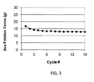
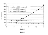
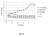
- the coating can exhibit lubricity. It will be appreciated that lubricity can be observed as relative low friction. In some embodiments, the coating can be lubricious after exposure to water. The coating can exhibit lubricity of between 0 and 50 grams of force when wetted as measured by a vertical pinch test, such as that described below. The coating can exhibit lubricity of between 0 and 40 grams of force when wetted as measured by a vertical pinch test, such as that described below. In yet other embodiments the coating can exhibit lubricity of between 0 and 30 grams of force when wetted as measured by a vertical pinch test, such as that described below. In some embodiments the coating can exhibit lubricity of less than about 20 grams of force when wetted. In some embodiments the coating can exhibit lubricity of less than about 15 grams of force when wetted.
- the lubricity of the coating can be a durable property.
- the lubricity can be retained over an extended period of time.
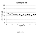
- lubricity can be maintained over a plurality of frictional testing cycles.
- the coating can exhibit a lubricity of between 0 and 30 grams of force when wetted for at least 10 consecutive testing cycles. In some embodiments, such as where at least 15 frictional test cycles are performed, the measured lubricity will increase no more than 30 % between the average of cycles 1-5 and the average of cycles 10-15 of the testing.
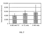
- the coating can exhibit a relatively low amount of particulate release when exposed to an aqueous environment.
- the coating will generate less than 70,000 particles of greater than 10 microns in size in an aqueous environment.
- the coating will generate less than 50,000 particles of greater than 10 microns in size in an aqueous environment.
- the coating will generate less than 30,000 particles of greater than 10 microns in size in an aqueous environment.
- the coating will generate less than 25,000 particles of greater than 10 microns in size in an aqueous environment.
- the coating will generate less than 20,000 particles of greater than 10 microns in size in an aqueous environment.
- the coating will generate less than 15,000 particles of greater than 10 microns in size in an aqueous environment. In some embodiments, the coating will generate less than 10,000 particles of greater than 10 microns in size in an aqueous environment. In some embodiments, the coating will generate less than 8,000 particles of greater than 10 microns in size in an aqueous environment. In some embodiments, the coating will generate less than 6,000 particles of greater than 10 microns in size in an aqueous environment. It will be appreciated that in accordance with various embodiments herein, the properties of lubricity and low particulate release are both present.
- photoreactive group and “photoreactive group” are used interchangeably and refer to a chemical moiety that is sufficiently stable to remain in an inactive state (i.e., ground state) under normal storage conditions but that can undergo a transformation from the inactive state to an activated state when subjected to an appropriate energy source.
- references to photoreactive groups herein shall also include the reaction products of the photoreactive groups.
- Photoreactive groups respond to specific applied external stimuli to undergo active specie generation with resultant covalent bonding to an adjacent chemical structure.
- a photoreactive group can be activated and can abstract a hydrogen atom from an alkyl group. A covalent bond can then form between the compound with the photoreactive group and the compound with the C-H bond.
- Suitable photoreactive groups are described in U.S. Pat. No. 5,002,582 , the disclosure of which is incorporated herein by reference.
- Photoreactive groups can be chosen to be responsive to various portions of actinic radiation. Typically, groups are chosen that can be photoactivated using either ultraviolet or visible radiation. Suitable photoreactive groups include, for example, azides, diazos, diazirines, ketones, and quinones. The photoreactive groups generate active species such as free radicals including, for example, nitrenes, carbenes, and excited states of ketones upon absorption of electromagnetic energy.
- the photoreactive group is an aryl ketone, such as acetophenone, benzophenone, anthrone, and anthrone-like heterocycles (i. e., heterocyclic analogs of anthrone such as those having N, O, or S in the 10-position), or their substituted (e.g., ring substituted) derivatives.
- aryl ketones include heterocyclic derivatives of anthrone, including acridone, xanthone, and thioxanthone, and their ring substituted derivatives.
- Other suitable photoreactive groups include quinone such as, for example anthraquinone.
- aryl ketones can undergo multiple activation/inactivation/reactivation cycles.
- benzophenone is capable of photochemical excitation with the initial formation of an excited singlet state that undergoes intersystem crossing to the triplet state.
- the excited triplet state can insert into carbon-hydrogen bonds by abstraction of a hydrogen atom (from a polymeric coating layer, for example), thus creating a radical pair.
- Subsequent collapse of the radical pair leads to formation of a new carbon-carbon bond.
- a reactive bond e.g., carbon/hydrogen
- the ultraviolet light-induced excitation of the benzophenone group is reversible and the molecule returns to ground state energy level upon removal of the energy source.
- Photoreactive aryl ketones such as benzophenone and acetophenone can undergo multiple reactivations in water and hence can provide increased coating efficiency.
- the azides constitute another class of photoreactive groups and include arylazides (C 6 R 5 N 3 ) such as phenyl azide and 4-fluoro-3-nitrophenyl azide; acyl azides (-CO-N 3 ) such as benzoyl azide and p-methylbenzoyl azide; azido formates (-O-CO-N 3 ) such as ethyl azidoformate and phenyl azidoformate; sulfonyl azides (-SO 2 -N 3 ) such as benzenesulfonyl azide; and phosphoryl azides (RO) 2 PON 3 such as diphenyl phosphoryl azide and diethyl phosphoryl azide.
- arylazides C 6 R 5 N 3
- acyl azides such as benzoyl azide and p-methylbenzoyl azide
- azido formates such as ethyl azidoformate and phenyl azid
- Diazo compounds constitute another class of photoreactive groups and include diazoalkanes (-CHN 2 ) such as diazomethane and diphenyldiazomethane; diazoketones (-CO-CHN 2 ) such as diazoacetophenone and 1-trifluoromethyl-1-diazo-2-pentanone; diazoacetates (-O-CO-CHN 2 ) such as t-butyl diazoacetate and phenyl diazoacetate; and beta-keto-alpha-diazoacetates (-CO-CN 2 -CO-O-) such as t-butyl alpha diazoacetoacetate.
- diazoalkanes -CHN 2
- diazoketones such as diazoacetophenone and 1-trifluoromethyl-1-diazo-2-pentanone
- diazoacetates -O-CO-CHN 2
- beta-keto-alpha-diazoacetates -CO-CN 2
- the photoreactive groups are aryl ketones, such as benzophenone.
- Cross-linking agents used in accordance with embodiments herein can include those with at least two photoreactive groups. Exemplary cross-linking agents are described in U.S. Publ. Pat. App. No. 2011/0245367 , the content of which is herein incorporated by reference in its entirety.
- the first and/or second crosslinking agent can have a molecular weight of less than about 1500 kDa. In some embodiments the crosslinking agent can have a molecular weight of less than about 1200, 1100, 1000, 900, 800, 700, 600, 500, or 400.
- At least one of the first and second cross-linking agents comprising a linking agent having formula Photo 1 -LG-Photo 2 , wherein Photo 1 and Photo 2 , independently represent at least one photoreactive group and LG represents a linking group comprising at least one silicon or at least one phosphorus atom, there is a covalent linkage between at least one photoreactive group and the linking group, wherein the covalent linkage between at least one photoreactive group and the linking group is interrupted by at least one heteroatom.
- At least one of the first and second cross-linking agents comprising a linking agent having a formula selected from: wherein R1, R2, R8 and R9 are any substitution; R3, R4, R6 and R7 are alkyl, aryl, or a combination thereof; R5 is any substitution; and each X, independently, is O, N, Se, S, or alkyl, or a combination thereof; wherein R1 and R5 are any substitution; R2 and R4 can be any substitution, except OH; R3 can be alkyl, aryl, or a combination thereof; and X, independently, are O, N, Se, S, alkylene, or a combination thereof; wherein R1, R2, R4 and R5 are any substitution; R3 is any substitution; R6 and R7 are alkyl, aryl, or a combination thereof; and each X can independently be O, N. Se, S, alkylene, or a combination thereof; and
- the cross-linking agent can be bis(4-benzoylphenyl) phosphate.
- the photoactivatable cross-linking agent can be ionic, and can have good solubility in an aqueous composition, such as the first and/or second coating composition.
- at least one ionic photoactivatable cross-linking agent is used to form the coating.
- an ionic photoactivatable cross-linking agent can crosslink the polymers within the second coating layer which can also improve the durability of the coating.
- the ionic photoactivatable cross-linking agent is a compound of formula I: X 1 --Y--X 2 where Y is a radical containing at least one acidic group, basic group, or a salt of an acidic group or basic group.
- X 1 and X 2 are each independently a radical containing a latent photoreactive group.
- the photoreactive groups can be the same as those described herein. Spacers can also be part of X 1 or X 2 along with the latent photoreactive group.
- the latent photoreactive group includes an aryl ketone or a quinone.
- the radical Y in formula I provides the desired water solubility for the ionic photoactivatable cross-linking agent.
- the water solubility (at room temperature and optimal pH) is at least about 0.05 mg/ml. In some embodiments, the solubility is about 0.1 to about 10 mg/ml or about 1 to about 5 mg/ml.
- Y is a radical containing at least one acidic group or salt thereof.
- a photoactivatable cross-linking agent can be anionic depending upon the pH of the coating composition.
- Suitable acidic groups include, for example, sulfonic acids, carboxylic acids, phosphonic acids, and the like.
- Suitable salts of such groups include, for example, sulfonate, carboxylate, and phosphate salts.
- the ionic cross-linking agent includes a sulfonic acid or sulfonate group.
- Suitable counter ions include alkali, alkaline earths metals, ammonium, protonated amines, and the like.
- a compound of formula I can have a radical Y that contains a sulfonic acid or sulfonate group; X 1 and X 2 can contain photoreactive groups such as aryl ketones.
- Such compounds include 4,5-bis(4-benzoylphenylmethyleneoxy)benzene-1,3-disulfonic acid or salt; 2,5-bis(4-benzoylphenylmethylencoxy)benzene-1,4-disulfonic acid or salt; 2,5-bis(4-benzoylmethyleneoxy)benzene-1-sulfonic acid or salt; N,N-bis[2-(4-benzoylbenzyloxy)ethyl]-2-aminoethanesulfonic acid or salt, and the like. See U.S. Pat. No. 6,278,018 .
- the counter ion of the salt can be, for example, ammonium or an alkali metal such as sodium, potassium, or lithium.
- Y can be a radical that contains a basic group or a salt thereof.
- Y radicals can include, for example, an ammonium, a phosphonium, or a sulfonium group. The group can be neutral or positively charged, depending upon the pH of the coating composition.
- the radical Y includes an ammonium group.
- Suitable counter ions include, for example, carboxylates, halides, sulfate, and phosphate.
- compounds of formula I can have a Y radical that contains an ammonium group; X 1 and X 2 can contain photoreactive groups that include aryl ketones.
- Such photoactivatable cross-linking agents include ethylenebis(4-benzoylbenzyldimethylammonium) salt; hexamethylenebis (4-benzoylbenzyldimethylammonium) salt; 1,4-bis(4-benzoylbenzyl)-1,4-dimethylpiperazinediium) salt, bis(4-benzoylbenzyl)hexamethylenetetraminediium salt, bis[2-(4-benzoylbenzyldimethylammonio)ethyl]-4-benzoylbenzylmethylammonium salt; 4,4-bis(4-benzoylbenzyl)morpholinium salt; ethylenebis[(2-(4-benzoylbenzyldimethylammonio)ethyl)-4-benzoylbenzylmethylammonium] salt; and 1,1,4,4-tetralds(4-benzoylbenzyl)piperzinediium salt. See U.S. Pat
- the ionic photoactivatable cross-linking agent can be a compound having the formula: wherein X 1 includes a first photoreactive group; X 2 includes a second photoreactive group; Y includes a core molecule; Z includes at least one charged group; D 1 includes a first degradable linker; and D 2 includes a second degradable linker.
- Additional exemplary degradable ionic photoactivatable cross-linking agents are described in US Patent Application Publication US 2011/0144373 (Swan et al. , "Water Soluble Degradable Crosslinker"), the disclosure of which is incorporated herein by reference.
- a non-ionic photoactivatable cross-linking agent can be used.
- the non-ionic photoactivatable cross-linking agent has the formula XR 1 R 2 R 3 R 4 , where X is a chemical backbone, and R 1 , R 2 , R 3 , and R 4 are radicals that include a latent photoreactive group.
- Exemplary non-ionic cross-linking agents are described, for example, in U.S. Pat. Nos. 5,414,075 and 5,637,460 (Swan et al. , "Restrained Multifunctional Reagent for Surface Modification"). Chemically, the first and second photoreactive groups, and respective spacers, can be the same or different.
- the non-ionic photoactivatable cross-linking agent can be represented by the formula: PG 2 -LE 2 -X-LE 1 -PG 1 wherein PG 1 and PG 2 include, independently, one or more photoreactive groups, for example, an aryl ketone photoreactive group, including, but not limited to, aryl ketones such as acetophenone, benzophenone, anthraquinone, anthrone, anthrone-like heterocycles, their substituted derivatives or a combination thereof; LE 1 and LE 2 are, independently, linking elements, including, for example, segments that include urea, carbamate, or a combination thereof; and X represents a core molecule, which can be either polymeric or non-polymeric, including, but not limited to a hydrocarbon, including a hydrocarbon that is linear, branched, cyclic, or a combination thereof; aromatic, non-aromatic, or a combination thereof; monocyclic, polycyclic, carbocyclic
- Non-ionic crosslinking agents are described, for example, in US Application Number 13/316,030 filed December 9, 2011 (Publ. No. US 2012/0149934 ) (Kurdyumov, "Photocrosslinker"), the disclosure of which is incorporated herein by reference.
- non-ionic photoactivatable cross-linking agents can include, for example, those described in US Provisional Application 61/494,724 filed June 8, 2011 (now U.S. App. No. 13/490,994 ) (Swan et al., "Photo-Vinyl Primers/Crosslinkers"), the disclosure of which is incorporated herein by reference.
- Exemplary cross-linking agents can include non-ionic photoactivatable cross-linking agents having the general formula R 1 - X- R 2 , wherein R 1 is a radical comprising a vinyl group, X is a radical comprising from about one to about twenty carbon atoms, and R 2 is a radical comprising a photoreactive group.
- Some suitable cross-linking agents are those formed by a mixture of the chemical backbone molecule (such as pentaerythritol) and an excess of a derivative of the photoreactive group (such as 4-bromomethylbenzophenone).
- An exemplary product is tetrakis(4-benzoylbenzyl ether) of pentaerythritol (tetrakis(4-benzoylphenylmethoxymethyl)methane). See U.S. Pat. Nos. 5,414,075 and 5,637,460 .
- a single photoactivatable cross-linking agent or any combination of photoactivatable cross-linking agents can be used in forming the coating.
- at least one nonionic cross-linking agent such as tetrakis(4-benzoylbenzyl ether) of pentaerythritol can be used with at least one ionic cross-linking agent.
- At least one non-ionic photoactivatable cross-linking agent can be used with at least one cationic photoactivatable cross-linking agent such as an ethylenebis(4-benzoylbenzyldimethylammonium) salt or at least one anionic photoactivatable cross-linking agent such as 4,5-bis(4-benzoylphenylmethyleneoxy)benzene-1,3-disulfonic acid or salt.
- at least one nonionic cross-linking agent can be used with at least one cationic cross-linking agent and at least one anionic cross-linking agent.
- a least one cationic cross-linking agent can be used with at least one anionic cross-linking agent but without a non-ionic cross-linking agent.
- An exemplary cross-linking agent is disodium 4,5-bis[(4-benzoylbenzyl)oxy]-1,3-benzenedisulfonate (DBDS).
- DBDS disodium 4,5-bis[(4-benzoylbenzyl)oxy]-1,3-benzenedisulfonate
- This reagent can be prepared by combining 4,5-Dihydroxylbenzyl-1,3-disulfonate (CHBDS) with 4-bromomethylbenzophenone (BMBP) in THF and sodium hydroxide, then refluxing and cooling the mixture followed by purification and recrystallization (also as described in U.S. Pat. No. 5,714,360 , incorporated herein by reference).
- CHBDS 4,5-Dihydroxylbenzyl-1,3-disulfonate
- BMBP 4-bromomethylbenzophenone
- a further exemplary cross-linking agent is ethylenebis (4-benzoylbenzyldimethylammonium) dibromide. This agent can be prepared as described in U.S. Pat. No. 5,714,360 , the content of which is herein incorporated by reference.
- cross-linking agents can include the cross-linking agents described in U.S. Publ. Pat. App. No. 2010/0274012 and U.S. Pat. No. 7,772,393 the content of all of which is herein incorporated by reference.
- cross-linking agents can include boron-containing linking agents including, but not limited to, the boron-containing linking agents disclosed in US 61/666,516 , entitled “Boron-Containing Linking Agents" by Kurdyumov et al., the content of which is herein incorporated by reference.
- linking agents can include borate, borazine, or boronate groups and coatings and devices that incorporate such linking agents, along with related methods.
- the linking agent includes a compound having the structure (I): wherein R 1 is a radical comprising a photoreactive group; R 2 is selected from OH and a radical comprising a photoreactive group, an akyl group and an aryl group; and R 3 is selected from OH and a radical comprising a photoreactive group.
- R 1 is a radical comprising a photoreactive group
- R 2 is selected from OH and a radical comprising a photoreactive group, an akyl group and an aryl group
- R 3 is selected from OH and a radical comprising a photoreactive group.
- the bonds B-R 1 , B-R 2 and B-R 3 can be chosen independently to be interrupted by a heteroatom, such as O, N, S, or mixtures thereof.
- Additional agents for use with embodiments herein can include stilbene-based reactive compounds including, but not limited to, those disclosed in US 61/736,436 , entitled “Stilbene-Based Reactive Compounds, Polymeric Matrices Formed Therefrom, and Articles Visualizable by Fluorescence” by Kurdyumov et al., the content of which is herein incorporated by reference.
- a first coating solution is formed by combining compounds with a solvent.
- the compounds can include comprising polyvinylpyrrolidone derivatized with a photoreactive group and a first cross-linking agent comprising at least two photoreactive groups.
- the first coating solution can also include non-derivatized polyvinylpyrrolidone.
- the solvent for the first coating solution can include various components.
- the solvent for the first coating solution can be 100% IPA.
- the solvent for the first coating solution can include water and isopropyl alcohol (IPA). The proportion of IPA to water can be between about 95 % IPA - 5 % water to about 10% IPA - 90% water.
- the ratio of EPA:water can be about 95:5, 90:10, 85:15, 80:20, 75:25, 70:30, 65:35, 60:40, 55:45, 50:50, 45:55, 40:60, 35:65, 30:70, 25:75, 20:80, 15:85, 10:90, or can be within a range with endpoints including any two of those ratios such that the total relative portions of IPA and water are equal to 100.
- the solvent can include about 75% isopropyl alcohol and about 25% water.
- exemplary polar solvents e.g. acetone, alcohols and DMSO
- exemplary polar solvents e.g. acetone, alcohols and DMSO
- a second coating solution is formed by combining compounds with a solvent.
- the compounds can include polyvinylpyrrolidone derivatized with a photoreactive group, a second cross-linking agent comprising at least two photoreactive groups, and a polymer comprising polyacrylamide, the polymer derivatized with at least one photoreactive group.
- the solvent for the second coating solution can include various components.
- the solvent for the second coating solution can include water and isopropyl alcohol (IPA). The proportion of IPA to water can be from about 0% IPA - 100 water to about 60 IPA - 40 water.
- the ratio of IPA:water can be about 0:100,5:95, 10:90, 15:85, 20:80, 25:75, 30:70, 35:65, 40:60, 45:55, 50:50, 55:45, 60:40, or can be within a range with endpoints including any two of those ratios such that the total relative portions of IPA and water are equal to 100.
- the solvent can include about 15% isopropyl alcohol and about 85% water.
- the viscosity of the solutions can vary. In some embodiments, the viscosity of the second solution is less than about 100 centipoise (cP). In some embodiments, the viscosity of the second solution is equal to or less than about 90, 80, 70 60, 50, 40, 30, 20, or 10 cP.
- the first coating solution can be applied to a substrate. Prior to application of the coating solution to the substrate, many different pretreatment steps can be taken.
- the surface of the substrate can be cleaned. For example, the surface can be wiped or dipped into an alcohol such as isopropyl alcohol.
- the substrate can be put into a detergent solution such as a VALTRON solution and sonicated.
- a compound can be disposed on the surface of the substrate to act as a tie layer.
- the surface of the substrate can be sterilized.
- exemplary techniques can include drop coating, blade coating, dip coating, spray coating, and the like.
- the solution is applied by dip coating.
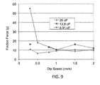
- the speed of dip coating can vary.
- the substrate can be dipped into the first coating solution and then withdrawn at speeds between 0.01 and 10 cm/s.
- the substrate can be dipped into the first coating solution and then withdrawn at speeds between 0.1 and 4 cm/s.
- the substrate can be dipped into the first coating solution and then withdrawn at speeds between 0.1 and 0.5 cm/s.
- the substrate can be withdrawn at speeds between 0.2 and 0.4 cm/s.
- the substrate can be withdrawn at speeds of about 0.3 cm/s.
- actinic radiation such as UV radiation
- actinic radiation can be applied to activate photoreactive groups within the components of the first coating solution forming the first layer.
- Actinic radiation can be provided by any suitable light source that promotes activation of the photoreactive groups.
- Preferred light sources (such as those available from Dymax Corp.) provide UV irradiation in the range of 190 nm to 360 nm.
- An exemplary UV light source is a Dymax 2000-EC series UV flood lamp with a 400 Watt metal halide bulb.
- a suitable dose of radiation is in the range of from about 0.5 mW/cm 2 to about 2.0 mW/cm 2 .
- the first coating solution can be dried, before or during application of the actinic radiation.
- the second coating solution can be applied on top of the first coating layer.
- Many different techniques can be used to apply the solution to the substrate.
- the solution is applied by dip coating.
- the speed of dip coating can vary.
- the substrate can be dipped into the second coating solution and then withdrawn at speeds between 0.01 and 10 cm/s.
- the substrate can be dipped into the second coating solution and then withdrawn at speeds between 0.1 and 4 cm/s.
- the substrate can be dipped into the second coating solution and then withdrawn at speeds between 0.1 and 0.5 cm/s.
- the substrate can be withdrawn at speeds between 0.2 and 0.4 cm/s.
- the substrate can be withdrawn at speeds of about 0.3 cm/s.
- actinic radiation such as UV radiation at a desirable wavelength
- the second coating solution can be dried, before or during application of the actinic radiation.
- Substrates can be partially or entirely fabricated from a metal, ceramic, glass, or the like, or a combination thereof.
- Substrates can include polymers such as polyurethanes and polyurethane copolymers, polyethylene, polyolefins, styrenebutadiene copolymers, polyisoprene, isobutylene-isoprene copolymers (butyl rubber), including halogenated butyl rubber, butadiene-styrene-acrylonitrile copolymers, silicone polymers, fluorosilicone polymers, polycarbonates, polyamides, polyesters, polyvinyl chloride, polyether-polyester copolymers, polyether-polyamide copolymers, and the like.
- the substrate can be made of a single material, or a combination of materials.
- Substrate polymers can also include those formed of synthetic polymers, including oligomers, homopolymers, and copolymers resulting from either addition or condensation polymerizations.
- suitable addition polymers include, but are not limited to, acrylics such as those polymerized from methyl acrylate, methyl methacrylate, hydroxyethyl methacrylate, hydroxyethyl acrylate, acrylic acid, methacrylic acid, glyceryl acrylate, glyceryl methacrylate, methacrylamide, and acrylamide; vinyls such as ethylene, propylene, vinyl chloride, vinyl acetate, vinyl pyrrolidone, vinylidene difluoride, and styrene.
- condensation polymers include, but are not limited to, nylons such as polycaprolactam, polylauryl lactam, polyhexamethylene adipamide, and polyhexamethylene dodecanediamide, and also polyurethanes, polycarbonates, polyamides, polysulfones, poly(ethylene terephthalate), polydimethylsiloxanes, and polyetherketone.
- the substrate includes a polymer selected from the group consisting of polyamide, polyimide, polyether block amide (PEBAX), polyether ether ketone (PEEK), high density polyethylene (HDPE), polyethylene, polyurethane, and polyethylene vinyl acetate.
- a polymer selected from the group consisting of polyamide, polyimide, polyether block amide (PEBAX), polyether ether ketone (PEEK), high density polyethylene (HDPE), polyethylene, polyurethane, and polyethylene vinyl acetate.
- Metals that can be used in medical articles include platinum, gold, or tungsten, as well as other metals such as rhenium, palladium, rhodium, ruthenium, titanium, nickel, and alloys of these metals, such as stainless steel, titanium/nickel, nitinol alloys, cobalt chrome alloys, non-ferrous alloys, and platinum/iridium alloys.
- One exemplary alloy is MP35.
- the methods and materials of the invention can be utilized to coat virtually any medical device for which it is desired to provide a hydrophilic and lubricious coating on a surface thereof.
- the coatings are particularly useful for medical articles that can be inserted into and moved within the body.
- Exemplary medical devices include vascular implants and grafts, surgical devices; synthetic prostheses; vascular prosthesis including endoprosthesis, stentgraft, and endovascular-stent combinations; small diameter grafts, abdominal aortic aneurysm grafts; wound dressings and wound management device; hemostatic barriers; mesh and hernia plugs; patches, including uterine bleeding patches, atrial septic defect (ASD) patches, patent foramen ovale (PFO) patches, ventricular septal defect (VSD) patches, and other generic cardiac patches; ASD, PFO, and VSD closures; percutaneous closure devices, mitral valve repair devices; left atrial appendage filters; valve annuloplasty devices, catheters; central venous access catheters, vascular access catheters, abscess drainage catheters, drug infusion catheters, parenteral feeding catheters, intravenous catheters (e.g., treated with antithrombotic agents), stroke therapy catheters, blood pressure and stent graft catheters; interventional cardio
- pacing delivering electricity, defibrillation
- anastomosis devices and anastomotic closures aneurysm exclusion devices
- biosensors such as glucose sensors; cardiac sensors (and other sensors for analytical purposes); birth control devices; breast implants; infection control devices; membranes; tissue scaffolds; tissue-related materials; shunts including cerebral spinal fluid (CSF) shunts, glaucoma drain shunts; dental devices and dental implants; ear devices such as ear drainage tubes, tympanostomy vent tubes; ophthalmic devices; cuffs and cuff portions of devices including drainage tube cuffs, implanted drug infusion tube cuffs, catheter cuff; sewing cuff; spinal and neurological devices; nerve regeneration conduits; neurological catheters; neuropatches; orthopedic devices such as orthopedic joint implants, bone repair/augmentation devices, cartilage repair devices; urological devices and urethral devices such as urological implants, bladder devices, renal devices and hemodialysis devices, colosto
- the device 200 can be, for example, a catheter, such as an angioplasty balloon catheter.
- Balloon catheter constructions are well known in the art and are described in various documents, for example, U.S. Patent Nos. 4,195,637 , 5,041,089 , 5,087,246 , 5,318,587 , 5,382,234 , 5,571,089 , 5,776,101 , 5,807,331 , 5,882,336 , 6,394,995 , 6,517,515 , 6,623,504 , 6,896,842 , and 7,163,523 .
- the device 200 includes a catheter shaft 202 and a manifold end 205.
- the device 200 also includes an inflatable balloon 204 disposed around the catheter shaft 202.
- the balloon 204 is shown in an inflated configuration.
- the catheter shaft 202 can include a channel to convey air through the catheter shaft 202 and to or from the balloon 204, so that the balloon 204 can selectively go from a deflated configuration to the inflated configuration and back again.
- the catheter shaft, and/or the balloon can have a coating, such as those described herein, disposed thereon.
- This reagent can be prepared as described in U.S. Pat. Nos. 4,979,959 ; 5,263,992 ; and 5,512,329 .
- Poly[acrylamide-co-sodium-2-acrylamido-2-methylpropanesulfonate-co-N-(3-(4-benzoylbenzamido)propyl)methacrylamide] was prepared according to the procedure described in US 4,973,493 , US 5,002,582 , and US 5,263,992 .
- Polyvinylpyrrolidone having an average molecular weight of about 1,450 kDa with benzophenone photoreactive groups was prepared according to the methods described in U.S. Patent No. 5,512,329 .
- cross-linking agent sodium bis(4-benzoylphenyl) phosphate was prepared according to the methods described in U.S. Publ. Pat. App. No. 2012/0046384 .
- Non-derivatized PVP e.g., unmodified PVP having an average molecular of 1,200 kDa was obtained from BASF.
- DBDS Disodium 4,5-bis[(4-benzoylbenzyl)oxy]-1,3-benzenedisulfonate
- This reagent can be prepared by combining 4,5-Dihydroxylbenzyl-1,3-disulfonate (CPIBDS) with 4-bromomethylbenzophenone (BMBP) in THF and sodium hydroxide, then refluxing and cooling the mixture followed by purification and recrystallization (also as described in U.S. Pat. No. 5,714,360 ).
- TriPhos tri-benzophenone phosphate
- a coating solution was prepared by mixing together Photo-PVP at 13 g/L; PVP-K90 at 5 g/L; and sodium bis(4-benzoylphenyl) phosphate at 1 g/L in a solvent of 75% isopropyl alcohol and 25% water.
- a coating solution was prepared by mixing together Photo-PVP at 10.5 g/L; PA-BBA-AMPS-PEG at 10.5 g/L; sodium bis(4-benzoylphenyl) phosphate at 0.1 g/L in a solvent of 15% isopropyl alcohol and 85% water.
- a third coating solution was prepared by mixing together Photo-PVP at 13 g/L and sodium bis(4-benzoylphenyl) phosphate at 1 g/L in a solvent of 75% isopropyl alcohol and 25 % water.
- a coating solution was prepared by mixing together Photo-PVP at 10.5 g/L; PA-AMPS-BBA-MA at 10.5 g/L; sodium bis(4-benzoylphenyl) phosphate at 0.1 g/L, in a solvent of 15% isopropyl alcohol and 85% water.
- a coating solution was prepared by mixing together Photo-PVP at 13 g/L; PVP-K90 at 5 g/L; and DBDS at 1 g/L in a solvent of 75% isopropyl alcohol and 25% water.
- a coating solution was prepared by mixing together Photo-PVP at 10.5 g/L; PA-BBA-AMPS-PEG at 10.5 g/L; DBDS at 0.1 g/L in a solvent of 15% isopropyl alcohol and 85% water.
- a coating solution was prepared by mixing together Photo-PVP at 16.36 g/L; and TetraPhos at 0.91 g/L in a solvent of 68%isopropyl alcohol and 32% acetone.
- a coating solution was prepared by mixing together Photo-PVP at 18 g/L; and TriPhos at 1 g/L in a solvent of 75%isopropyl alcohol and 25% acetone.
- a coating solution was prepared by mixing together Photo-PVP at 18 g/L; and DSE at 1 g/L in a solvent of 75%isopropyl alcohol and 25% water.
- a coating solution was prepared by mixing together Photo-PVP at 10 g/L; PA-BBA-AMPs-PEG at 10.5 g/L; and DSE at 0.1 g/L in a solvent of 25%isopropyl alcohol and 75% water.
- a coating solution was prepared by mixing together Photo-PVP at 18 g/L; and BPP at 1 g/L in a solvent of 75%isopropyl alcohol and 25% water.
- Test substrates included Pebax rods (72D; 63D; and 35D - 40% BASO 4 ) obtained from Medicine Lake Extrusion, National, MN; NYLON-12 rods obtained from Medicine Lake Extrusion, National, MN; PEEK rods obtained from Zeus, Orangeburg, SC; and high-density polyethylene (HDPE) rods available from Universal Plastics, Denver, CO.
- Pebax rods 72D; 63D; and 35D - 40% BASO 4
- NYLON-12 rods obtained from Medicine Lake Extrusion, National, MN
- PEEK rods obtained from Zeus, Orangeburg, SC
- HDPE high-density polyethylene
- the coated substrates of the examples were evaluated for lubricity/durability by friction measurements using a Vertical Pinch Method, as described in International Application Number WO 03/055611 with the following modifications.
- the coated substrates samples were inserted into the end of a rod holder, which was placed between the two jaws of a pinch tester and immersed in a cylinder of water or saline.
- the jaws of the pinch tester were closed as the sample was pulled in a vertical direction for 10 cm at a travel rate of 1 cm/sec and opened when the coated sample was returned to the original position.
- a 750 g force was applied as the coated substrates were pulled up through the pinched jaws. The pull force exerted on the substrate was then measured (grams).
- Pull force (g) is equal to the coefficient of friction (COF) multiplied by pinch force (g).
- COF coefficient of friction
- the distal portion of a 6 French guide catheter (Vista Brite Tip, Cordis) was cut off and discarded so that the catheter was 30 cm long.
- the guide catheter was inserted into the ASTM F2394-07 model.
- a hemostasis valve connector (Qosina) was attached to the guide catheter.
- the model was cleaned by flushing 120 ml Isoton (Becton, Dickinson, and Company) using a 60 ml syringe and discarding the flush.
- a base line flush with 60 ml Isoton was analyzed by light obscuration to determine background level of particulates.
- 60-cm rods (1 mm diameter) with 20 cm coated were hydrated in Isoton for ⁇ 1 minute.
- the rods were inserted into the guide catheter and advanced until the distal portion of the rod exited the model.
- a 30 ml flush with Isoton was performed and collected in a glass beaker.
- the rod was removed and an additional 30 ml flush with Isoton was performed into the same glass beaker.
- the collected Isoton was immediately analyzed by light obscuration for particulates ⁇ 10 and ⁇ 25 microns.
- the model was cleaned with 120 ml Isoton and the next coated rod was tested.
- Coating solution A was applied to the substrate (72D Pebax rods) using a dip coat method. Specifically, the substrate was immersed in the base coat coating solution with a dwell time of 5 seconds. The substrate was then extracted from the solution at a speed of 0.3 cm/s. The first layer was then air dried for at least 10 minutes. The first layer was then UV cured. Specifically the coated substrate was rotated in front of a Dymax 2000-EC series UV flood lamp with a 400 Watt metal halide bulb for 3 minutes, approximately 20 cm from the light source.
- coating solution B was applied to the first layer, also by dip coating at the same speed to form the second layer.
- the second layer was then air dried and UV cured using the same conditions as for the first layer.
- Coating solution A was applied to the substrate (72D Pebax rods) using a dip coat method. Specifically, the substrate was immersed in the base coat coating solution with a dwell time of 5 seconds. The substrate was then extracted from the solution at a speed of 0.3 cm/s. The first layer was then air dried for at least 10 minutes. The first layer was then UV cured. Specifically the coated substrate was rotated in front of a Dymax 2000-EC series UV flood lamp with a 400 Watt metal halide bulb for 3 minutes, approximately 20 cm from the light source.
- Particulate generation testing was also performed. For an average of 3 rods, it was found that the PA-AMPS-BBA-MA group generated 4,447(+/-567) particulates greater than 10 microns in size and the PA-BBA-AMPS-PEG group generated 4,140(+/-725) particulates greater than 10 microns in size.
- Coatings were deposited onto each of Pebax rods (72D; 63D; and 35D - 40% BASO 4 ), NYLON-12 rods, PEEK rods, and HDPE rods.
- coating solution A was applied to each substrate using a dip coat method. Specifically, the substrate was immersed in the base coat coating solution with a dwell time of 5 seconds. The substrate was then extracted from the solution at a speed of 0.3 cm/s. The first layer was then air dried for at least 10 minutes. The first layer was then UV cured. Specifically the coated substrate was rotated in front of a Dymax 2000-EC series UV flood lamp with a 400 Watt metal halide bulb for 3 minutes, approximately 20 cm from the light source.
- coating solution B was applied to the first layer, also by dip coating at the same speed to form the second layer.
- the second layer was then air dried and UV cured using the same conditions as for the first layer.
- coating solution A was applied to the substrate (72D Pebax rods) using a dip coat method. Specifically, the substrate was immersed in the base coat coating solution with a dwell time of 5 seconds. The substrate was then extracted from the solution at a speed of 0.3 cm/s. The first layer was then air dried for at least 10 minutes. The first layer was then UV cured. Specifically the coated substrate was rotated in front of a Dymax 2000-EC series UV flood lamp with a 400 Watt metal halide bulb for 3 minutes, approximately 20 cm from the light source. Next, another layer of coating solution A was applied to the first layer, also by dip coating at the same speed to form the second layer. The second layer was then air dried and UV cured using the same conditions as for the first layer.
- coating solution B was applied to the substrate (72D Pebax rods) using a dip coat method. Specifically, the substrate was immersed in the base coat coating solution with a dwell time of 5 seconds. The substrate was then extracted from the solution at a speed of 0.3 cm/s. The first layer was then air dried for at least 10 minutes. The first layer was then UV cured. Specifically the coated substrate was rotated in front of a Dymax 2000-EC series UV flood lamp with a 400 Watt metal halide bulb for 3 minutes, approximately 20 cm from the light source. Next, another layer of coating solution B was applied to the first layer, also by dip coating at the same speed to form the second layer. The second layer was then air dried and UV cured using the same conditions as for the first layer.
- coating solution A was applied to the substrate (72D Pebax rods) using a dip coat method. Specifically, the substrate was immersed in the base coat coating solution with a dwell time of 5 seconds. The substrate was then extracted from the solution at a speed of 0.3 cm/s. The first layer was then air dried for at least 10 minutes. The first layer was then UV cured. Specifically the coated substrate was rotated in front of a Dymax 2000-EC series UV flood lamp with a 400 Watt metal halide bulb for 3 minutes, approximately 20 cm from the light source. Next, a layer of coating solution B was applied to the first layer, also by dip coating at the same speed to form the second layer. The second layer was then air dried and UV cured using the same conditions as for the first layer.
- the friction of the coating was then tested according to the testing procedure outlined above. The results are shown in FIG. 6 .
- Table 1 includes a summary of the coating thickness measurements and the calculated swelling ratio for each slide. Table 1. Summary of the coating thickness measurements and the calculated swelling ratio for each slide.
- a first set (“In BC- base coat and TC - top coat") of rods coating solution A was applied to the substrate (72D Pebax rods) using a dip coat method. Specifically, the substrate was immersed in the base coat coating solution with a dwell time of 5 seconds. The substrate was then extracted from the solution at a speed of 0.3 cm/s. The first layer was then air dried for at least 10 minutes. The first layer was then UV cured. Specifically the coated substrate was rotated in front of a Dymax 2000-EC series UV flood lamp with a 400 Watt metal halide bulb for 3 minutes, approximately 20 cm from the light source. Next, a layer of coating solution B was applied to the first layer, also by dip coating at the same speed to form the second layer. The second layer was then air dried and UV cured using the same conditions as for the first layer.
- a coating solution similar to A, except without sodium bis(4-benzoylphenyl) phosphate was applied to the substrate (72D Pebax rods) using a dip coat method. Specifically, the substrate was immersed in the base coat coating solution with a dwell time of 5 seconds. The substrate was then extracted from the solution at a speed of 0.3 cm/s. The first layer was then air dried for at least 10 minutes. The first layer was then UV cured. Specifically the coated substrate was rotated in front of a Dymax 2000-EC series UV flood lamp with a 400 Watt metal halide bulb for 3 minutes, approximately 20 cm from the light source. Next, a layer of coating solution B was applied to the first layer, also by dip coating at the same speed to form the second layer. The second layer was then air-dried and UV cured using the same conditions as for the first layer.
- a third set (“In BC Only") of rods coating solution A was applied to the substrate (72D Pebax rods) using a dip coat method. Specifically, the substrate was immersed in the base coat coating solution with a dwell time of 5 seconds. The substrate was then extracted from the solution at a speed of 0.3 cm/s. The first layer was then air dried for at least 10 minutes. The first layer was then UV cured. Specifically the coated substrate was rotated in front of a Dymax 2000-EC series UV flood lamp with a 400 Watt metal halide bulb for 3 minutes, approximately 20 cm from the light source.
- the second layer was then air dried and UV cured using the same conditions as for the first layer.
- the particulate generation of the coating was then tested according to the testing procedure outlined above. The results are shown in FIG. 7 .
- Coating solution A was applied to the substrate (72D Pebax rods) using a dip coat method. Specifically, the substrate was immersed in the base coat coating solution with a dwell time of 5 seconds. The substrate was then extracted from the solution at a speed of 0.3 cm/s. The first layer was then air dried for at least 10 minutes. The first layer was then UV cured. Specifically the coated substrate was rotated in front of a Dymax 2000-EC series UV flood lamp with a 400 Watt metal halide bulb for 3 minutes, approximately 20 cm from the light source.
- a layer of a coating solution was applied to the first layer, also by dip coating at the same speed to form the second layer.
- the different solutions used for the second coating layer were similar to coating solution B but the ratios of Photo-PVP: PA-BBA-AMPS-PEG varied. For the control, the ratio was 1:1 as in coating solution B. The other ratios were 1:2 and 2:1.
- the photo-PVP was eliminated entirely.
- the PA-BBA-AMPS-PEG (PBAP) was eliminated entirely.
- the second layer was then air dried and UV cured using the same conditions as for the first layer.
- Coating solution C was applied to a plurality of substrates (72D Pebax rods) using a dip coat method. Specifically, the substrate was immersed in the base coat coating solution with a dwell time of 5 seconds. The substrate was then extracted from the solution at a speed of 1.0 cm/s. The first layer was then UV cured without first drying. Specifically the coated substrate was rotated in front of a Dymax 2000-EC series UV flood lamp with a 400 Watt metal halide bulb for 30 seconds, approximately 20 cm from the light source.
- Variations of coating solution B were prepared. One variation had a solids concentration sufficient to result in a coating solution with a viscosity of 20 cP. Another variation had a solids concentration sufficient to result in a coating solution with a viscosity of 13.8 cP. Yet another variation had a solids concentration sufficient to result in a coating solution with a viscosity of 8.91 cP.
- the substrate was then immersed in the coat coating solutions with a dwell time of 5 seconds and varying extraction speeds including 0.3; 0.5; 0.8; 1; 1.5; and 2 cm/s. The second layer was not allowed to dry, but immediately UV cured. Specifically the coated substrate was rotated in front of a Dymax 2000-EC series UV flood lamp with a 400 Watt metal halide bulb for 30 seconds, approximately 20 cm from the light source.
- Particulates for the coatings were then tested according to the testing procedure outlined above. The results are shown in FIG. 10 .
- Coating solution E was applied to the substrate (72D Pebax rods) using a dip coat method. Specifically, the substrate was immersed in the base coat coating solution with a dwell time of 5 seconds. The substrate was then extracted from the solution at a speed of 0.3 cm/s. The first layer was then air dried for at least 10 minutes. The first layer was then UV cured. Specifically the coated substrate was rotated in front of a Dymax 2000-EC series UV flood lamp with a 400 Watt metal halide bulb for 3 minutes, approximately 20 cm from the light source.
- coating solution F was applied to the first layer, also by dip coating at the same speed to form the second layer.
- the second layer was then air dried and UV cured using the same conditions as for the first layer.
- the phrase “configured” describes a system, apparatus, or other structure that is constructed or configured to perform a particular task or adopt a particular configuration to.
- the phrase “configured” can be used interchangeably with other similar phrases such as arranged and configured, constructed and arranged, constructed, manufactured and arranged, and the like.
Landscapes
- Health & Medical Sciences (AREA)
- General Health & Medical Sciences (AREA)
- Veterinary Medicine (AREA)
- Public Health (AREA)
- Epidemiology (AREA)
- Life Sciences & Earth Sciences (AREA)
- Animal Behavior & Ethology (AREA)
- Chemical & Material Sciences (AREA)
- Medicinal Chemistry (AREA)
- Transplantation (AREA)
- Heart & Thoracic Surgery (AREA)
- Dermatology (AREA)
- Surgery (AREA)
- Oral & Maxillofacial Surgery (AREA)
- Vascular Medicine (AREA)
- Paints Or Removers (AREA)
- Materials For Medical Uses (AREA)
- Chemical Kinetics & Catalysis (AREA)
- Polymers & Plastics (AREA)
- Organic Chemistry (AREA)
- Laminated Bodies (AREA)
- Application Of Or Painting With Fluid Materials (AREA)
Applications Claiming Priority (4)
| Application Number | Priority Date | Filing Date | Title |
|---|---|---|---|
| US201261587944P | 2012-01-18 | 2012-01-18 | |
| US201261587929P | 2012-01-18 | 2012-01-18 | |
| EP13704280.0A EP2804915B1 (fr) | 2012-01-18 | 2013-01-18 | Revêtement de dispositif médical lubrifié à faibles particules |
| PCT/US2013/022202 WO2013109930A1 (fr) | 2012-01-18 | 2013-01-18 | Revêtement de dispositif médical lubrifié à faibles particules |
Related Parent Applications (2)
| Application Number | Title | Priority Date | Filing Date |
|---|---|---|---|
| EP13704280.0A Division EP2804915B1 (fr) | 2012-01-18 | 2013-01-18 | Revêtement de dispositif médical lubrifié à faibles particules |
| EP13704280.0A Division-Into EP2804915B1 (fr) | 2012-01-18 | 2013-01-18 | Revêtement de dispositif médical lubrifié à faibles particules |
Publications (2)
| Publication Number | Publication Date |
|---|---|
| EP3012301A1 true EP3012301A1 (fr) | 2016-04-27 |
| EP3012301B1 EP3012301B1 (fr) | 2023-08-16 |
Family
ID=47714540
Family Applications (2)
| Application Number | Title | Priority Date | Filing Date |
|---|---|---|---|
| EP13704280.0A Active EP2804915B1 (fr) | 2012-01-18 | 2013-01-18 | Revêtement de dispositif médical lubrifié à faibles particules |
| EP15198514.0A Active EP3012301B1 (fr) | 2012-01-18 | 2013-01-18 | Revêtement de dispositif médical lubrifié avec un nombre réduit de particules |
Family Applications Before (1)
| Application Number | Title | Priority Date | Filing Date |
|---|---|---|---|
| EP13704280.0A Active EP2804915B1 (fr) | 2012-01-18 | 2013-01-18 | Revêtement de dispositif médical lubrifié à faibles particules |
Country Status (10)
| Country | Link |
|---|---|
| US (5) | US9375517B2 (fr) |
| EP (2) | EP2804915B1 (fr) |
| JP (3) | JP6117824B2 (fr) |
| CN (1) | CN104185661B (fr) |
| BR (1) | BR112014017675B1 (fr) |
| CA (1) | CA2861314C (fr) |
| CR (1) | CR20140349A (fr) |
| MX (1) | MX356582B (fr) |
| RU (1) | RU2627390C2 (fr) |
| WO (1) | WO2013109930A1 (fr) |
Cited By (6)
| Publication number | Priority date | Publication date | Assignee | Title |
|---|---|---|---|---|
| US9737639B2 (en) | 2012-01-18 | 2017-08-22 | Surmodics, Inc. | Lubricious medical device coating with low particulates |
| US9861727B2 (en) | 2011-05-20 | 2018-01-09 | Surmodics, Inc. | Delivery of hydrophobic active agent particles |
| US9999675B2 (en) | 2012-11-05 | 2018-06-19 | Surmodics, Inc. | Composition and method for delivery of hydrophobic active agents |
| US10213529B2 (en) | 2011-05-20 | 2019-02-26 | Surmodics, Inc. | Delivery of coated hydrophobic active agent particles |
| US10342898B2 (en) | 2015-12-29 | 2019-07-09 | Surmodics, Inc. | Lubricious coatings with surface salt groups |
| US11174447B2 (en) | 2015-12-29 | 2021-11-16 | Surmodics, Inc. | Lubricious coatings with surface salt groups |
Families Citing this family (15)
| Publication number | Priority date | Publication date | Assignee | Title |
|---|---|---|---|---|
| CN105214143A (zh) | 2009-04-28 | 2016-01-06 | 苏尔莫迪克斯公司 | 用于递送生物活性剂的装置和方法 |
| US11246963B2 (en) | 2012-11-05 | 2022-02-15 | Surmodics, Inc. | Compositions and methods for delivery of hydrophobic active agents |
| EP2941279B1 (fr) * | 2013-01-04 | 2023-05-17 | SurModics, Inc. | Revêtement lubrifiant à faible taux de matières particulaires pourvu de couches contenant un polymère de vinyle pyrrolidone et d'acide acrylique |
| AU2014311454A1 (en) * | 2013-08-25 | 2016-03-24 | Biotectix, LLC | Conductive polymeric coatings, medical devices, coating solutions and methods |
| US10124088B2 (en) | 2014-09-29 | 2018-11-13 | Surmodics, Inc. | Lubricious medical device elements |
| EP3878484A1 (fr) | 2015-04-16 | 2021-09-15 | Hollister Incorporated | Revêtements hydrophiles et leurs procédés de formation |
| CN105251095B (zh) * | 2015-10-22 | 2018-05-15 | 江苏康诺医疗器械有限公司 | Pvc超滑导尿管及其制备方法 |
| WO2017173114A1 (fr) * | 2016-03-31 | 2017-10-05 | Surmodics, Inc. | Revêtement lubrifiant pour dispositif médical |
| US10898446B2 (en) | 2016-12-20 | 2021-01-26 | Surmodics, Inc. | Delivery of hydrophobic active agents from hydrophilic polyether block amide copolymer surfaces |
| CN112368309B (zh) * | 2018-06-27 | 2022-09-09 | 泰尔茂株式会社 | 亲水性共聚物及医疗器械 |
| US12037560B2 (en) | 2019-10-21 | 2024-07-16 | Biocoat, Incorporated | UV cure topcoatings for medical devices |
| EP4048332A4 (fr) * | 2019-10-21 | 2023-12-20 | Biocoat, Incorporated | Revêtements à polymérisation par uv pour dispositifs médicaux |
| US11359156B2 (en) * | 2019-10-21 | 2022-06-14 | Biocoat, Inc. | UV cure basecoatings for medical devices |
| WO2023172686A1 (fr) * | 2022-03-09 | 2023-09-14 | Surmodics Coatings, LLC | Revêtements thromborésistants, dispositifs revêtus et procédés |
| WO2024148271A1 (fr) | 2023-01-05 | 2024-07-11 | Surmodics, Inc. | Revêtements lubrifiants pour dispositifs médicaux à durabilité améliorée |
Citations (25)
| Publication number | Priority date | Publication date | Assignee | Title |
|---|---|---|---|---|
| US4195637A (en) | 1977-10-21 | 1980-04-01 | Schneider Medintag Ag | Catheter arrangement, method of catheterization, and method of manufacturing a dilatation element |
| US4973493A (en) | 1982-09-29 | 1990-11-27 | Bio-Metric Systems, Inc. | Method of improving the biocompatibility of solid surfaces |
| US4979959A (en) | 1986-10-17 | 1990-12-25 | Bio-Metric Systems, Inc. | Biocompatible coating for solid surfaces |
| US5041089A (en) | 1987-12-11 | 1991-08-20 | Devices For Vascular Intervention, Inc. | Vascular dilation catheter construction |
| US5087246A (en) | 1988-12-29 | 1992-02-11 | C. R. Bard, Inc. | Dilation catheter with fluted balloon |
| US5263992A (en) | 1986-10-17 | 1993-11-23 | Bio-Metric Systems, Inc. | Biocompatible device with covalently bonded biocompatible agent |
| US5318587A (en) | 1989-08-25 | 1994-06-07 | C. R. Bard, Inc. | Pleated balloon dilatation catheter and method of use |
| US5382234A (en) | 1993-04-08 | 1995-01-17 | Scimed Life Systems, Inc. | Over-the-wire balloon catheter |
| US5414075A (en) | 1992-11-06 | 1995-05-09 | Bsi Corporation | Restrained multifunctional reagent for surface modification |
| US5512329A (en) | 1982-09-29 | 1996-04-30 | Bsi Corporation | Substrate surface preparation |
| US5571089A (en) | 1993-06-30 | 1996-11-05 | Cardiovascular Dynamics, Inc. | Low profile perfusion catheter |
| US5714360A (en) | 1995-11-03 | 1998-02-03 | Bsi Corporation | Photoactivatable water soluble cross-linking agents containing an onium group |
| US5776101A (en) | 1990-10-04 | 1998-07-07 | Schneider (Europe) A.G. | Balloon dilatation catheter |
| US5807331A (en) | 1994-04-20 | 1998-09-15 | Cordis Corporation | Active perfusion dilatation catheter |
| US5882336A (en) | 1994-12-30 | 1999-03-16 | Janacek; Jaroslav | Dilation catheter |
| US6278018B1 (en) | 1999-12-14 | 2001-08-21 | Surmodics, Inc. | Surface coating agents |
| US6394995B1 (en) | 1998-05-15 | 2002-05-28 | X Technologies Inc. | Enhanced balloon dilatation system |
| US6517515B1 (en) | 1998-03-04 | 2003-02-11 | Scimed Life Systems, Inc. | Catheter having variable size guide wire lumen |
| WO2003055611A1 (fr) | 2001-12-21 | 2003-07-10 | Surmodics, Inc. | Reactif et procede permettant de fournir des revetements sur des surfaces |
| US6623504B2 (en) | 2000-12-08 | 2003-09-23 | Scimed Life Systems, Inc. | Balloon catheter with radiopaque distal tip |
| US6896842B1 (en) | 1993-10-01 | 2005-05-24 | Boston Scientific Corporation | Medical device balloons containing thermoplastic elastomers |
| US7163523B2 (en) | 2003-02-26 | 2007-01-16 | Scimed Life Systems, Inc. | Balloon catheter |
| US20110144373A1 (en) * | 2009-12-10 | 2011-06-16 | Surmodics, Inc. | Water-soluble degradable photo-crosslinker |
| US20110245367A1 (en) * | 2010-03-30 | 2011-10-06 | Surmodics, Inc. | Degradable photo-crosslinker |
| US20120149934A1 (en) | 2010-12-13 | 2012-06-14 | Surmodics, Inc. | Photo-crosslinker |
Family Cites Families (54)
| Publication number | Priority date | Publication date | Assignee | Title |
|---|---|---|---|---|
| US4156065A (en) | 1977-01-21 | 1979-05-22 | The Upjohn Company | Catalytic condensation of isocyanates and carboxylic acids or anhydrides |
| US5002582A (en) | 1982-09-29 | 1991-03-26 | Bio-Metric Systems, Inc. | Preparation of polymeric surfaces via covalently attaching polymers |
| EP0166998B1 (fr) | 1984-06-04 | 1991-05-08 | TERUMO KABUSHIKI KAISHA trading as TERUMO CORPORATION | Instrument médical et son procédé de fabrication |
| US5001009A (en) | 1987-09-02 | 1991-03-19 | Sterilization Technical Services, Inc. | Lubricious hydrophilic composite coated on substrates |
| US5091205A (en) | 1989-01-17 | 1992-02-25 | Union Carbide Chemicals & Plastics Technology Corporation | Hydrophilic lubricious coatings |
| US4990357A (en) | 1989-05-04 | 1991-02-05 | Becton, Dickinson And Company | Elastomeric segmented hydrophilic polyetherurethane based lubricious coatings |
| US5135516A (en) | 1989-12-15 | 1992-08-04 | Boston Scientific Corporation | Lubricious antithrombogenic catheters, guidewires and coatings |
| US5039485A (en) | 1990-09-26 | 1991-08-13 | Union Carbide Industrial Gases Technology Corporation | Sterilization method |
| US5670558A (en) | 1994-07-07 | 1997-09-23 | Terumo Kabushiki Kaisha | Medical instruments that exhibit surface lubricity when wetted |
| US5554120A (en) | 1994-07-25 | 1996-09-10 | Advanced Cardiovascular Systems, Inc. | Polymer blends for use in making medical devices including catheters and balloons for dilatation catheters |
| US5849846A (en) | 1994-07-25 | 1998-12-15 | Advanced Cardiovascular Systems, Inc. | Balloons for medical catheters |
| US5662960A (en) | 1995-02-01 | 1997-09-02 | Schneider (Usa) Inc. | Process for producing slippery, tenaciously adhering hydrogel coatings containing a polyurethane-urea polymer hydrogel commingled with a poly (n-vinylpyrrolidone) polymer hydrogel |
| US5731087A (en) | 1995-06-07 | 1998-03-24 | Union Carbide Chemicals & Plastics Technology Corporation | Lubricious coatings containing polymers with vinyl and carboxylic acid moieties |
| JP3336600B2 (ja) | 1996-04-18 | 2002-10-21 | ニプロ株式会社 | 医療用ガイドワイヤーおよびその製造方法 |
| SE9602529D0 (sv) * | 1996-06-26 | 1996-06-26 | Astra Ab | Medical device |
| JP3362186B2 (ja) | 1996-08-09 | 2003-01-07 | ニプロ株式会社 | 医療用具およびその製造方法 |
| US5858653A (en) | 1997-09-30 | 1999-01-12 | Surmodics, Inc. | Reagent and method for attaching target molecules to a surface |
| JP4183024B2 (ja) | 1997-10-20 | 2008-11-19 | 日本シャーウッド株式会社 | 潤滑性被覆を有する医療用具及びその製造方法 |
| US6221425B1 (en) | 1998-01-30 | 2001-04-24 | Advanced Cardiovascular Systems, Inc. | Lubricious hydrophilic coating for an intracorporeal medical device |
| US6007833A (en) | 1998-03-19 | 1999-12-28 | Surmodics, Inc. | Crosslinkable macromers bearing initiator groups |
| US6176849B1 (en) | 1999-05-21 | 2001-01-23 | Scimed Life Systems, Inc. | Hydrophilic lubricity coating for medical devices comprising a hydrophobic top coat |
| JP4143883B2 (ja) | 1999-07-06 | 2008-09-03 | 日本シャーウッド株式会社 | 医療用具およびその製造方法 |
| MXPA03001406A (es) | 2000-08-15 | 2004-05-04 | Surmodics Inc | Matriz de incorporacion de medicamento. |
| KR101121675B1 (ko) | 2002-04-19 | 2012-03-13 | 노파르티스 아게 | 신규 생체적합물질, 그의 제조방법 및 용도 |
| US7192484B2 (en) | 2002-09-27 | 2007-03-20 | Surmodics, Inc. | Advanced coating apparatus and method |
| CN1813059A (zh) * | 2003-05-02 | 2006-08-02 | 西格玛-奥尔德利希公司 | 固相细胞裂解和捕获平台 |
| EP2329852A1 (fr) | 2004-03-26 | 2011-06-08 | SurModics, Inc. | Composition et procédé permettant de preparer des surfaces biocompatibles |
| WO2006063181A1 (fr) | 2004-12-06 | 2006-06-15 | Surmodics, Inc. | Articles medicaux multifonctionnels |
| JP2008541950A (ja) | 2005-06-02 | 2008-11-27 | サーモディクス,インコーポレイティド | 医療用製品向けの親水性ポリマーコーティング |
| US7772393B2 (en) | 2005-06-13 | 2010-08-10 | Innovative Surface Technologies, Inc. | Photochemical crosslinkers for polymer coatings and substrate tie-layer |
| EP2679254A1 (fr) | 2006-07-25 | 2014-01-01 | Coloplast A/S | Photo-durcissement de revêtements thermoplastiques |
| US20080213334A1 (en) * | 2006-09-29 | 2008-09-04 | Lockwood Nathan A | Polyelectrolyte media for bioactive agent delivery |
| MX339467B (es) | 2007-02-28 | 2016-05-27 | Dsm Ip Assets Bv | Recubrimiento hidrofilo. |
| EP2125061A2 (fr) * | 2007-02-28 | 2009-12-02 | DSM IP Assets B.V. | Revêtement hydrophile |
| US20090186059A1 (en) | 2008-01-14 | 2009-07-23 | Johnson Elizabeth E | Devices and methods for elution of nucleic acid delivery complexes |
| WO2009112548A1 (fr) | 2008-03-12 | 2009-09-17 | Dsm Ip Assets B.V. | Revêtement hydrophile |
| WO2009126830A2 (fr) | 2008-04-09 | 2009-10-15 | Surmodics, Inc. | Administration de complexes d'acide nucléique depuis des matériaux comprenant des groupes chargés négativement |
| CN105214143A (zh) | 2009-04-28 | 2016-01-06 | 苏尔莫迪克斯公司 | 用于递送生物活性剂的装置和方法 |
| US8927000B2 (en) | 2010-06-30 | 2015-01-06 | Surmodics, Inc. | Lipid coating for medical devices delivering bioactive agent |
| JP5690631B2 (ja) | 2011-03-30 | 2015-03-25 | 日本コヴィディエン株式会社 | 潤滑性を有する医療用具およびその製造方法 |
| US9861727B2 (en) * | 2011-05-20 | 2018-01-09 | Surmodics, Inc. | Delivery of hydrophobic active agent particles |
| US20130143056A1 (en) | 2011-06-08 | 2013-06-06 | Surmodics, Inc. | Photo-vinyl linking agents |
| MX356582B (es) | 2012-01-18 | 2018-06-05 | Surmodics Inc | Recubrimiento para dispositivo medico lubrico con bajo nivel de material particulado. |
| MX351261B (es) | 2012-06-01 | 2017-10-06 | Surmodics Inc | Aparato y método para recubrir catéteres con globo. |
| EP2866849B1 (fr) | 2012-06-29 | 2020-02-19 | SurModics, Inc. | Revêtements de fixation cellulaire et procédés à l'aide d'un photoréactif contenant du phosphore |
| EP2692365A1 (fr) | 2012-08-03 | 2014-02-05 | MaRVis Medical GmbH | Dispositif médical implantable ou insérable détectable par IRM doté dýun revêtement comportant des ions paramagnétiques et son procédé de préparation |
| US9629945B2 (en) | 2012-12-12 | 2017-04-25 | Surmodics, Inc. | Stilbene-based reactive compounds, polymeric matrices formed therefrom, and articles visualizable by fluorescence |
| US9340876B2 (en) | 2012-12-12 | 2016-05-17 | Applied Materials, Inc. | Mask for deposition process |
| EP2941279B1 (fr) * | 2013-01-04 | 2023-05-17 | SurModics, Inc. | Revêtement lubrifiant à faible taux de matières particulaires pourvu de couches contenant un polymère de vinyle pyrrolidone et d'acide acrylique |
| WO2015029625A1 (fr) | 2013-09-02 | 2015-03-05 | テルモ株式会社 | Instrument médical et son procédé de fabrication |
| WO2015075142A1 (fr) | 2013-11-20 | 2015-05-28 | Dsm Ip Assets B.V. | Réduction de la détérioration de revêtements hydrophiles mouillés comprenant de l'eau soumise à une stérilisation par rayonnement |
| US10124088B2 (en) | 2014-09-29 | 2018-11-13 | Surmodics, Inc. | Lubricious medical device elements |
| US10342898B2 (en) | 2015-12-29 | 2019-07-09 | Surmodics, Inc. | Lubricious coatings with surface salt groups |
| US11174447B2 (en) | 2015-12-29 | 2021-11-16 | Surmodics, Inc. | Lubricious coatings with surface salt groups |
-
2013
- 2013-01-18 MX MX2014008670A patent/MX356582B/es active IP Right Grant
- 2013-01-18 CN CN201380005717.9A patent/CN104185661B/zh active Active
- 2013-01-18 EP EP13704280.0A patent/EP2804915B1/fr active Active
- 2013-01-18 WO PCT/US2013/022202 patent/WO2013109930A1/fr active Application Filing
- 2013-01-18 US US13/745,397 patent/US9375517B2/en active Active
- 2013-01-18 JP JP2014553466A patent/JP6117824B2/ja active Active
- 2013-01-18 RU RU2014133462A patent/RU2627390C2/ru active
- 2013-01-18 CA CA2861314A patent/CA2861314C/fr active Active
- 2013-01-18 BR BR112014017675-2A patent/BR112014017675B1/pt active IP Right Grant
- 2013-01-18 EP EP15198514.0A patent/EP3012301B1/fr active Active
-
2014
- 2014-07-21 CR CR20140349A patent/CR20140349A/es unknown
-
2016
- 2016-05-26 US US15/165,650 patent/US9737639B2/en active Active
-
2017
- 2017-03-23 JP JP2017057269A patent/JP6408056B2/ja active Active
- 2017-07-07 US US15/643,564 patent/US10905802B2/en active Active
-
2018
- 2018-09-19 JP JP2018174717A patent/JP6675459B2/ja active Active
-
2021
- 2021-01-28 US US17/161,396 patent/US11872325B2/en active Active
-
2024
- 2024-01-15 US US18/412,843 patent/US20240342345A1/en active Pending
Patent Citations (28)
| Publication number | Priority date | Publication date | Assignee | Title |
|---|---|---|---|---|
| US4195637A (en) | 1977-10-21 | 1980-04-01 | Schneider Medintag Ag | Catheter arrangement, method of catheterization, and method of manufacturing a dilatation element |
| US4973493A (en) | 1982-09-29 | 1990-11-27 | Bio-Metric Systems, Inc. | Method of improving the biocompatibility of solid surfaces |
| US5512329A (en) | 1982-09-29 | 1996-04-30 | Bsi Corporation | Substrate surface preparation |
| US5263992A (en) | 1986-10-17 | 1993-11-23 | Bio-Metric Systems, Inc. | Biocompatible device with covalently bonded biocompatible agent |
| US4979959A (en) | 1986-10-17 | 1990-12-25 | Bio-Metric Systems, Inc. | Biocompatible coating for solid surfaces |
| US5041089A (en) | 1987-12-11 | 1991-08-20 | Devices For Vascular Intervention, Inc. | Vascular dilation catheter construction |
| US5087246A (en) | 1988-12-29 | 1992-02-11 | C. R. Bard, Inc. | Dilation catheter with fluted balloon |
| US5318587A (en) | 1989-08-25 | 1994-06-07 | C. R. Bard, Inc. | Pleated balloon dilatation catheter and method of use |
| US5776101A (en) | 1990-10-04 | 1998-07-07 | Schneider (Europe) A.G. | Balloon dilatation catheter |
| US5414075A (en) | 1992-11-06 | 1995-05-09 | Bsi Corporation | Restrained multifunctional reagent for surface modification |
| US5637460A (en) | 1992-11-06 | 1997-06-10 | Bsi Corporation | Restrained multifunctional reagent for surface modification |
| US5382234A (en) | 1993-04-08 | 1995-01-17 | Scimed Life Systems, Inc. | Over-the-wire balloon catheter |
| US5571089A (en) | 1993-06-30 | 1996-11-05 | Cardiovascular Dynamics, Inc. | Low profile perfusion catheter |
| US6896842B1 (en) | 1993-10-01 | 2005-05-24 | Boston Scientific Corporation | Medical device balloons containing thermoplastic elastomers |
| US5807331A (en) | 1994-04-20 | 1998-09-15 | Cordis Corporation | Active perfusion dilatation catheter |
| US5882336A (en) | 1994-12-30 | 1999-03-16 | Janacek; Jaroslav | Dilation catheter |
| US5714360A (en) | 1995-11-03 | 1998-02-03 | Bsi Corporation | Photoactivatable water soluble cross-linking agents containing an onium group |
| US6517515B1 (en) | 1998-03-04 | 2003-02-11 | Scimed Life Systems, Inc. | Catheter having variable size guide wire lumen |
| US6394995B1 (en) | 1998-05-15 | 2002-05-28 | X Technologies Inc. | Enhanced balloon dilatation system |
| US6278018B1 (en) | 1999-12-14 | 2001-08-21 | Surmodics, Inc. | Surface coating agents |
| US6623504B2 (en) | 2000-12-08 | 2003-09-23 | Scimed Life Systems, Inc. | Balloon catheter with radiopaque distal tip |
| WO2003055611A1 (fr) | 2001-12-21 | 2003-07-10 | Surmodics, Inc. | Reactif et procede permettant de fournir des revetements sur des surfaces |
| US7348055B2 (en) | 2001-12-21 | 2008-03-25 | Surmodics, Inc. | Reagent and method for providing coatings on surfaces |
| US7163523B2 (en) | 2003-02-26 | 2007-01-16 | Scimed Life Systems, Inc. | Balloon catheter |
| US20110144373A1 (en) * | 2009-12-10 | 2011-06-16 | Surmodics, Inc. | Water-soluble degradable photo-crosslinker |
| US20110245367A1 (en) * | 2010-03-30 | 2011-10-06 | Surmodics, Inc. | Degradable photo-crosslinker |
| US20120046384A2 (en) | 2010-03-30 | 2012-02-23 | Surmodics, Inc. | Photoactivatable crosslinker |
| US20120149934A1 (en) | 2010-12-13 | 2012-06-14 | Surmodics, Inc. | Photo-crosslinker |
Cited By (12)
| Publication number | Priority date | Publication date | Assignee | Title |
|---|---|---|---|---|
| US9861727B2 (en) | 2011-05-20 | 2018-01-09 | Surmodics, Inc. | Delivery of hydrophobic active agent particles |
| US10213528B2 (en) | 2011-05-20 | 2019-02-26 | Surmodics, Inc. | Delivery of hydrophobic active agent particles |
| US10213529B2 (en) | 2011-05-20 | 2019-02-26 | Surmodics, Inc. | Delivery of coated hydrophobic active agent particles |
| US10617793B2 (en) | 2011-05-20 | 2020-04-14 | Surmodics, Inc. | Delivery of hydrophobic active agent particles |
| US11529440B2 (en) | 2011-05-20 | 2022-12-20 | Surmodics, Inc. | Delivery of hydrophobic active agent particles |
| US12083249B2 (en) | 2011-05-20 | 2024-09-10 | Surmodics, Inc. | Delivery of hydrophobic active agent particles |
| US9737639B2 (en) | 2012-01-18 | 2017-08-22 | Surmodics, Inc. | Lubricious medical device coating with low particulates |
| US10905802B2 (en) | 2012-01-18 | 2021-02-02 | Surmodics, Inc. | Lubricious medical device coating with low particulates |
| US11872325B2 (en) | 2012-01-18 | 2024-01-16 | Surmodics, Inc. | Lubricious medical device coating with low particulates |
| US9999675B2 (en) | 2012-11-05 | 2018-06-19 | Surmodics, Inc. | Composition and method for delivery of hydrophobic active agents |
| US10342898B2 (en) | 2015-12-29 | 2019-07-09 | Surmodics, Inc. | Lubricious coatings with surface salt groups |
| US11174447B2 (en) | 2015-12-29 | 2021-11-16 | Surmodics, Inc. | Lubricious coatings with surface salt groups |
Also Published As
| Publication number | Publication date |
|---|---|
| CN104185661A (zh) | 2014-12-03 |
| EP2804915A1 (fr) | 2014-11-26 |
| JP6117824B2 (ja) | 2017-04-19 |
| US10905802B2 (en) | 2021-02-02 |
| RU2014133462A (ru) | 2016-03-10 |
| CR20140349A (es) | 2014-11-24 |
| US9375517B2 (en) | 2016-06-28 |
| JP6675459B2 (ja) | 2020-04-01 |
| BR112014017675A2 (fr) | 2017-06-20 |
| BR112014017675A8 (pt) | 2017-07-11 |
| US20130197433A1 (en) | 2013-08-01 |
| JP6408056B2 (ja) | 2018-10-17 |
| JP2017127669A (ja) | 2017-07-27 |
| JP2015503998A (ja) | 2015-02-05 |
| US20240342345A1 (en) | 2024-10-17 |
| EP2804915B1 (fr) | 2016-03-30 |
| JP2018198983A (ja) | 2018-12-20 |
| WO2013109930A1 (fr) | 2013-07-25 |
| CA2861314C (fr) | 2021-03-16 |
| EP3012301B1 (fr) | 2023-08-16 |
| CA2861314A1 (fr) | 2013-07-25 |
| US9737639B2 (en) | 2017-08-22 |
| MX2014008670A (es) | 2014-10-14 |
| BR112014017675B1 (pt) | 2021-06-22 |
| US11872325B2 (en) | 2024-01-16 |
| MX356582B (es) | 2018-06-05 |
| US20210220525A1 (en) | 2021-07-22 |
| RU2627390C2 (ru) | 2017-08-08 |
| US20160271300A1 (en) | 2016-09-22 |
| CN104185661B (zh) | 2016-08-17 |
| US20170304506A1 (en) | 2017-10-26 |
Similar Documents
| Publication | Publication Date | Title |
|---|---|---|
| US11872325B2 (en) | Lubricious medical device coating with low particulates | |
| JP7224409B2 (ja) | 医療デバイス用潤滑コーティング | |
| EP3397296B1 (fr) | Revêtements lubrifiés comprenant des groupes salins de surface | |
| US11174447B2 (en) | Lubricious coatings with surface salt groups | |
| AU2014256955A1 (en) | Coatings for controlled release of highly water soluble drugs | |
| US20230285641A1 (en) | Thromboresistant coatings, coated devices, and methods |
Legal Events
| Date | Code | Title | Description |
|---|---|---|---|
| PUAI | Public reference made under article 153(3) epc to a published international application that has entered the european phase |
Free format text: ORIGINAL CODE: 0009012 |
|
| 17P | Request for examination filed |
Effective date: 20151208 |
|
| AC | Divisional application: reference to earlier application |
Ref document number: 2804915 Country of ref document: EP Kind code of ref document: P |
|
| AK | Designated contracting states |
Kind code of ref document: A1 Designated state(s): AL AT BE BG CH CY CZ DE DK EE ES FI FR GB GR HR HU IE IS IT LI LT LU LV MC MK MT NL NO PL PT RO RS SE SI SK SM TR |
|
| STAA | Information on the status of an ep patent application or granted ep patent |
Free format text: STATUS: EXAMINATION IS IN PROGRESS |
|
| 17Q | First examination report despatched |
Effective date: 20190510 |
|
| STAA | Information on the status of an ep patent application or granted ep patent |
Free format text: STATUS: EXAMINATION IS IN PROGRESS |
|
| GRAP | Despatch of communication of intention to grant a patent |
Free format text: ORIGINAL CODE: EPIDOSNIGR1 |
|
| STAA | Information on the status of an ep patent application or granted ep patent |
Free format text: STATUS: GRANT OF PATENT IS INTENDED |
|
| INTG | Intention to grant announced |
Effective date: 20230313 |
|
| GRAS | Grant fee paid |
Free format text: ORIGINAL CODE: EPIDOSNIGR3 |
|
| P01 | Opt-out of the competence of the unified patent court (upc) registered |
Effective date: 20230529 |
|
| GRAA | (expected) grant |
Free format text: ORIGINAL CODE: 0009210 |
|
| STAA | Information on the status of an ep patent application or granted ep patent |
Free format text: STATUS: THE PATENT HAS BEEN GRANTED |
|
| AC | Divisional application: reference to earlier application |
Ref document number: 2804915 Country of ref document: EP Kind code of ref document: P |
|
| AK | Designated contracting states |
Kind code of ref document: B1 Designated state(s): AL AT BE BG CH CY CZ DE DK EE ES FI FR GB GR HR HU IE IS IT LI LT LU LV MC MK MT NL NO PL PT RO RS SE SI SK SM TR |
|
| REG | Reference to a national code |
Ref country code: GB Ref legal event code: FG4D |
|
| REG | Reference to a national code |
Ref country code: CH Ref legal event code: EP Ref country code: DE Ref legal event code: R096 Ref document number: 602013084462 Country of ref document: DE |
|
| REG | Reference to a national code |
Ref country code: IE Ref legal event code: FG4D |
|
| REG | Reference to a national code |
Ref country code: LT Ref legal event code: MG9D |
|
| REG | Reference to a national code |
Ref country code: NL Ref legal event code: MP Effective date: 20230816 |
|
| REG | Reference to a national code |
Ref country code: AT Ref legal event code: MK05 Ref document number: 1600060 Country of ref document: AT Kind code of ref document: T Effective date: 20230816 |
|
| PG25 | Lapsed in a contracting state [announced via postgrant information from national office to epo] |
Ref country code: GR Free format text: LAPSE BECAUSE OF FAILURE TO SUBMIT A TRANSLATION OF THE DESCRIPTION OR TO PAY THE FEE WITHIN THE PRESCRIBED TIME-LIMIT Effective date: 20231117 |
|
| PGFP | Annual fee paid to national office [announced via postgrant information from national office to epo] |
Ref country code: GB Payment date: 20231130 Year of fee payment: 12 |
|
| PG25 | Lapsed in a contracting state [announced via postgrant information from national office to epo] |
Ref country code: IS Free format text: LAPSE BECAUSE OF FAILURE TO SUBMIT A TRANSLATION OF THE DESCRIPTION OR TO PAY THE FEE WITHIN THE PRESCRIBED TIME-LIMIT Effective date: 20231216 |
|
| PG25 | Lapsed in a contracting state [announced via postgrant information from national office to epo] |
Ref country code: SE Free format text: LAPSE BECAUSE OF FAILURE TO SUBMIT A TRANSLATION OF THE DESCRIPTION OR TO PAY THE FEE WITHIN THE PRESCRIBED TIME-LIMIT Effective date: 20230816 Ref country code: RS Free format text: LAPSE BECAUSE OF FAILURE TO SUBMIT A TRANSLATION OF THE DESCRIPTION OR TO PAY THE FEE WITHIN THE PRESCRIBED TIME-LIMIT Effective date: 20230816 Ref country code: PT Free format text: LAPSE BECAUSE OF FAILURE TO SUBMIT A TRANSLATION OF THE DESCRIPTION OR TO PAY THE FEE WITHIN THE PRESCRIBED TIME-LIMIT Effective date: 20231218 Ref country code: NO Free format text: LAPSE BECAUSE OF FAILURE TO SUBMIT A TRANSLATION OF THE DESCRIPTION OR TO PAY THE FEE WITHIN THE PRESCRIBED TIME-LIMIT Effective date: 20231116 Ref country code: NL Free format text: LAPSE BECAUSE OF FAILURE TO SUBMIT A TRANSLATION OF THE DESCRIPTION OR TO PAY THE FEE WITHIN THE PRESCRIBED TIME-LIMIT Effective date: 20230816 Ref country code: LV Free format text: LAPSE BECAUSE OF FAILURE TO SUBMIT A TRANSLATION OF THE DESCRIPTION OR TO PAY THE FEE WITHIN THE PRESCRIBED TIME-LIMIT Effective date: 20230816 Ref country code: LT Free format text: LAPSE BECAUSE OF FAILURE TO SUBMIT A TRANSLATION OF THE DESCRIPTION OR TO PAY THE FEE WITHIN THE PRESCRIBED TIME-LIMIT Effective date: 20230816 Ref country code: IS Free format text: LAPSE BECAUSE OF FAILURE TO SUBMIT A TRANSLATION OF THE DESCRIPTION OR TO PAY THE FEE WITHIN THE PRESCRIBED TIME-LIMIT Effective date: 20231216 Ref country code: HR Free format text: LAPSE BECAUSE OF FAILURE TO SUBMIT A TRANSLATION OF THE DESCRIPTION OR TO PAY THE FEE WITHIN THE PRESCRIBED TIME-LIMIT Effective date: 20230816 Ref country code: GR Free format text: LAPSE BECAUSE OF FAILURE TO SUBMIT A TRANSLATION OF THE DESCRIPTION OR TO PAY THE FEE WITHIN THE PRESCRIBED TIME-LIMIT Effective date: 20231117 Ref country code: FI Free format text: LAPSE BECAUSE OF FAILURE TO SUBMIT A TRANSLATION OF THE DESCRIPTION OR TO PAY THE FEE WITHIN THE PRESCRIBED TIME-LIMIT Effective date: 20230816 Ref country code: AT Free format text: LAPSE BECAUSE OF FAILURE TO SUBMIT A TRANSLATION OF THE DESCRIPTION OR TO PAY THE FEE WITHIN THE PRESCRIBED TIME-LIMIT Effective date: 20230816 |
|
| PGFP | Annual fee paid to national office [announced via postgrant information from national office to epo] |
Ref country code: IE Payment date: 20231211 Year of fee payment: 12 Ref country code: FR Payment date: 20231212 Year of fee payment: 12 |
|
| PG25 | Lapsed in a contracting state [announced via postgrant information from national office to epo] |
Ref country code: PL Free format text: LAPSE BECAUSE OF FAILURE TO SUBMIT A TRANSLATION OF THE DESCRIPTION OR TO PAY THE FEE WITHIN THE PRESCRIBED TIME-LIMIT Effective date: 20230816 |
|
| PG25 | Lapsed in a contracting state [announced via postgrant information from national office to epo] |
Ref country code: ES Free format text: LAPSE BECAUSE OF FAILURE TO SUBMIT A TRANSLATION OF THE DESCRIPTION OR TO PAY THE FEE WITHIN THE PRESCRIBED TIME-LIMIT Effective date: 20230816 |
|
| PG25 | Lapsed in a contracting state [announced via postgrant information from national office to epo] |
Ref country code: SM Free format text: LAPSE BECAUSE OF FAILURE TO SUBMIT A TRANSLATION OF THE DESCRIPTION OR TO PAY THE FEE WITHIN THE PRESCRIBED TIME-LIMIT Effective date: 20230816 Ref country code: RO Free format text: LAPSE BECAUSE OF FAILURE TO SUBMIT A TRANSLATION OF THE DESCRIPTION OR TO PAY THE FEE WITHIN THE PRESCRIBED TIME-LIMIT Effective date: 20230816 Ref country code: ES Free format text: LAPSE BECAUSE OF FAILURE TO SUBMIT A TRANSLATION OF THE DESCRIPTION OR TO PAY THE FEE WITHIN THE PRESCRIBED TIME-LIMIT Effective date: 20230816 Ref country code: EE Free format text: LAPSE BECAUSE OF FAILURE TO SUBMIT A TRANSLATION OF THE DESCRIPTION OR TO PAY THE FEE WITHIN THE PRESCRIBED TIME-LIMIT Effective date: 20230816 Ref country code: DK Free format text: LAPSE BECAUSE OF FAILURE TO SUBMIT A TRANSLATION OF THE DESCRIPTION OR TO PAY THE FEE WITHIN THE PRESCRIBED TIME-LIMIT Effective date: 20230816 Ref country code: CZ Free format text: LAPSE BECAUSE OF FAILURE TO SUBMIT A TRANSLATION OF THE DESCRIPTION OR TO PAY THE FEE WITHIN THE PRESCRIBED TIME-LIMIT Effective date: 20230816 Ref country code: SK Free format text: LAPSE BECAUSE OF FAILURE TO SUBMIT A TRANSLATION OF THE DESCRIPTION OR TO PAY THE FEE WITHIN THE PRESCRIBED TIME-LIMIT Effective date: 20230816 |
|
| PGFP | Annual fee paid to national office [announced via postgrant information from national office to epo] |
Ref country code: DE Payment date: 20231128 Year of fee payment: 12 |
|
| REG | Reference to a national code |
Ref country code: DE Ref legal event code: R097 Ref document number: 602013084462 Country of ref document: DE |
|
| PLBE | No opposition filed within time limit |
Free format text: ORIGINAL CODE: 0009261 |
|
| STAA | Information on the status of an ep patent application or granted ep patent |
Free format text: STATUS: NO OPPOSITION FILED WITHIN TIME LIMIT |
|
| 26N | No opposition filed |
Effective date: 20240517 |
|
| PG25 | Lapsed in a contracting state [announced via postgrant information from national office to epo] |
Ref country code: IT Free format text: LAPSE BECAUSE OF FAILURE TO SUBMIT A TRANSLATION OF THE DESCRIPTION OR TO PAY THE FEE WITHIN THE PRESCRIBED TIME-LIMIT Effective date: 20230816 Ref country code: SI Free format text: LAPSE BECAUSE OF FAILURE TO SUBMIT A TRANSLATION OF THE DESCRIPTION OR TO PAY THE FEE WITHIN THE PRESCRIBED TIME-LIMIT Effective date: 20230816 |
|
| PG25 | Lapsed in a contracting state [announced via postgrant information from national office to epo] |
Ref country code: MC Free format text: LAPSE BECAUSE OF FAILURE TO SUBMIT A TRANSLATION OF THE DESCRIPTION OR TO PAY THE FEE WITHIN THE PRESCRIBED TIME-LIMIT Effective date: 20230816 |
|
| PG25 | Lapsed in a contracting state [announced via postgrant information from national office to epo] |
Ref country code: MC Free format text: LAPSE BECAUSE OF FAILURE TO SUBMIT A TRANSLATION OF THE DESCRIPTION OR TO PAY THE FEE WITHIN THE PRESCRIBED TIME-LIMIT Effective date: 20230816 |
|
| REG | Reference to a national code |
Ref country code: CH Ref legal event code: PL |
|
| PG25 | Lapsed in a contracting state [announced via postgrant information from national office to epo] |
Ref country code: LU Free format text: LAPSE BECAUSE OF NON-PAYMENT OF DUE FEES Effective date: 20240118 |
|
| PG25 | Lapsed in a contracting state [announced via postgrant information from national office to epo] |
Ref country code: LU Free format text: LAPSE BECAUSE OF NON-PAYMENT OF DUE FEES Effective date: 20240118 |
|
| PG25 | Lapsed in a contracting state [announced via postgrant information from national office to epo] |
Ref country code: BE Free format text: LAPSE BECAUSE OF NON-PAYMENT OF DUE FEES Effective date: 20240131 |