EP3012016B1 - Powder-processing device - Google Patents
Powder-processing device Download PDFInfo
- Publication number
- EP3012016B1 EP3012016B1 EP14813160.0A EP14813160A EP3012016B1 EP 3012016 B1 EP3012016 B1 EP 3012016B1 EP 14813160 A EP14813160 A EP 14813160A EP 3012016 B1 EP3012016 B1 EP 3012016B1
- Authority
- EP
- European Patent Office
- Prior art keywords
- impact
- fixing ring
- impact pin
- rotor
- pins
- Prior art date
- Legal status (The legal status is an assumption and is not a legal conclusion. Google has not performed a legal analysis and makes no representation as to the accuracy of the status listed.)
- Active
Links
Images


Classifications
-
- B—PERFORMING OPERATIONS; TRANSPORTING
- B02—CRUSHING, PULVERISING, OR DISINTEGRATING; PREPARATORY TREATMENT OF GRAIN FOR MILLING
- B02C—CRUSHING, PULVERISING, OR DISINTEGRATING IN GENERAL; MILLING GRAIN
- B02C19/00—Other disintegrating devices or methods
- B02C19/0012—Devices for disintegrating materials by collision of these materials against a breaking surface or breaking body and/or by friction between the material particles (also for grain)
- B02C19/0018—Devices for disintegrating materials by collision of these materials against a breaking surface or breaking body and/or by friction between the material particles (also for grain) using a rotor accelerating the materials centrifugally against a circumferential breaking surface
-
- B—PERFORMING OPERATIONS; TRANSPORTING
- B02—CRUSHING, PULVERISING, OR DISINTEGRATING; PREPARATORY TREATMENT OF GRAIN FOR MILLING
- B02C—CRUSHING, PULVERISING, OR DISINTEGRATING IN GENERAL; MILLING GRAIN
- B02C13/00—Disintegrating by mills having rotary beater elements ; Hammer mills
- B02C13/10—Disintegrating by mills having rotary beater elements ; Hammer mills with horizontal rotor shaft and axial flow
-
- B—PERFORMING OPERATIONS; TRANSPORTING
- B02—CRUSHING, PULVERISING, OR DISINTEGRATING; PREPARATORY TREATMENT OF GRAIN FOR MILLING
- B02C—CRUSHING, PULVERISING, OR DISINTEGRATING IN GENERAL; MILLING GRAIN
- B02C13/00—Disintegrating by mills having rotary beater elements ; Hammer mills
- B02C13/26—Details
- B02C13/28—Shape or construction of beater elements
- B02C13/2804—Shape or construction of beater elements the beater elements being rigidly connected to the rotor
Definitions
- the present invention relates to an assembly.
- Patent Literature 1 a powder processing apparatus is proposed in which, by using an impact type striking means, a fine solid particle is embedded or fixed on the other solid particle, or a fine solid particle is fixed in a membranous on a surface of the other solid particle. Then, a surface modification process is carried out to the solid particle, and also a spheroidization process is carried out to an irregular particle such as metal and resin.
- Patent Literature 2 discloses a powder treating device in which a sufficient gap for circulating a powder is secured between an impact member and a front cover, and the diameter of the inner periphery of an impact ring is gradually increased toward the front cover.
- Operation conditions of a powder processing apparatus need to be set so that such as ambient temperature in an impact chamber is balanced with physical properties of powder to be processed.
- an object of the present invention is to provide an assembly comprising a powder processing apparatus capable of easily obtaining an operation condition in which such as ambient temperature in an impact chamber is balanced with physical properties of powder to be processed.
- an impact pin group may be formed in which one ends of multiple impact pins are fixed to an impact pin fixing member, the impact pin fixing member is detachably attached to the rotor, and multiple types of the impact pin groups in which the impact pins have different lengths in height direction are prepared.
- the impact pin fixing member may be attached to the rotor by screwing in an axial direction parallel to the rotating shaft and firmly fixed since a large screw can be used in comparison with the case where the detachable portion is attached to the fixing portion by screwing in a radial direction.
- the impact pin group in which multiple impact pins are integrated by being fixed to the impact pin fixing member can be attached to and detached from the rotor in a state in which the rotor is attached to the rotating shaft. Therefore, attachment/detachment can be easily operated in comparison with the case where each detachable portion is attached to each fixing portion after the rotor is detached from the rotating shaft.
- each detachable portion is attached to each fixing portion after the rotor is detached from the rotating shaft, even if the balance is kept in a state in which the detachable portion is once attached to the fixing portion, the detachable portion needs to be attached to the same fixing portion as before in the case where the same detachable portion is again used after once being detached. Therefore, parts can be easily managed and handled in the case where multiple impact pins are integrally fixed to an impact pin fixing portion.
- each one ends of the impact pins on a side opposite to a side facing the rotor may be fixed to a fixing ring.
- an assembly comprising a powder processing apparatus which is capable of easily obtaining operation conditions in which such as ambient temperature in an impact chamber is balanced with physical properties of powder to be processed.
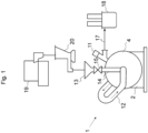
- a powder processing apparatus 1 includes a main body casing 2, a rear cover 3, a front cover 4, a rotor 5, an impact pin 6, a rotating shaft 7, and a collision ring 8 (see Figs. 1 to 9 ).
- the rotor 5 has a disc shape and rotates around the rotating shaft 7 extending in a substantially horizontal direction at a high speed in an impact chamber A which is a space surrounded by the rear cover 3, the front cover 4, and the collision ring 8.
- the impact pin 6 has a blade shape, and multiple impact pins 6 are radially attached at predetermined intervals on a front surface of the rotor 5.
- the impact pin 6 includes a fixing portion 6a and a detachable portion 6b.
- the fixing portion 6a has a substantially trapezoidal column shape, and a width is reduced toward a center of the rotating shaft 7.
- the detachable portion 6b is detachably attached to the fixing portion 6a.
- the fixing portion 6a is attached to the rotor 5 by welding.
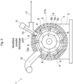
- Fig. 2 illustrates an example (a middle-sized apparatus) in which eight impact pins 6 are attached to the rotor 5 to specifically indicate an internal structure of the powder processing apparatus 1.
- Figs. 6 and 9 illustrate examples (a large-sized apparatus, as the apparatus becomes large, the impact pins are increased), in which sixteen impact pins 6 are attached to the rotor 5 to specifically indicate a structure of the impact pin 6.
- a groove 6a2 is provided on an outermost raceway surface of the fixing portion 6a.
- the groove 6a2 extends in a longitudinal direction parallel to an axial direction of the rotating shaft 7 and has a substantially dovetail groove shape in which a projected portion (tenon) provided in a longitudinal direction of the detachable portion 6b is engaged.
- the substantially dovetail groove shape according to the first embodiment is not limited to a trapezoidal shape in which a sectional surface is opened on an upper side and includes a groove shape in which an opening is narrower than a bottom such as a projected shape in which a sectional surface is opened at an upper portion (a projected portion at a center) .
- Multiple tap holes 6a3 are cut in the groove 6a2 to fix the detachable portion 6b.
- a tip portion 6b1 and an engaging portion 6b2 are integrally included in the detachable portion 6b.
- the tip portion 6b1 has a rectangular parallelepiped shape in which a length and a width (thickness) in a longitudinal direction (axial direction) of the fixing portion 6a are almost the same.
- the engaging portion 6b2 has almost the same shape as the groove 6a2.
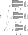
- Multiple types of the detachable portions 6b are prepared in which the height of a substantially rectangular parallelepiped shape forming the tip portion 6b1 (length in a radial direction of a disc included in the rotor 5) is different (see Fig. 8 ).
- detachable portions 6b are prepared so that an interval between an outermost raceway surface of the impact pin 6 and the collision ring 8 becomes, for example, 5 to 30 mm, when the detachable portion 6b is attached to the fixing portion 6a, although it depends on an apparatus size.
- screw holes 6b3 are provided in the same number as the above tap holes 6a3 at positions corresponding to the tap holes 6a3.
- the screw holes 6b3 penetrate the tip portion 6b1 and the engaging portion 6b2 in a height direction of the rectangular parallelepiped shape.
- the detachable portion 6b is attached to the fixing portion 6a by sliding the engaging portion 6b2 of the detachable portion 6b in an axial direction and sliding the engaging portion 6b2 into the groove 6a2 of the fixing portion 6a, and the detachable portion 6b is fixed to the fixing portion 6a by inserting such as a bolt with a hexagonal hole (not illustrated) into the screw hole 6b3 of the detachable portion 6b and tightening the bolt into the tap hole 6a3 of the groove 6a2.
- the length of the impact pin 6 in a radial direction can be adjusted by detachably attaching the detachable portion 6b to the fixing portion 6a. Therefore, an interval between a tip (a side opposite to the fixing portion 6a) of the detachable portion 6b and the collision ring 8 can be adjusted by choosing the detachable portions 6b having different heights.
- the collision ring 8 has a substantially cylindrical shape surrounding the rotor 5 and the impact pin 6.
- the collision ring 8 is peripherally disposed along an outermost raceway surface of the detachable portion 6b attached to the fixing portion 6a and disposed at constant intervals with respect to the detachable portion 6b.
- a modified powder discharge port is provided by partially cutting an upper portion of the collision ring 8.
- a discharge port opening/closing valve 9 closely contacting with and fitting to the modified powder discharge port is provided to the modified powder discharge port.
- a valve shaft 10 of the discharge port opening/closing valve 9 and an actuator 11 driving and operating the discharge port opening/closing valve 9 via the valve shaft 10 are provided to the modified powder discharge port.
- a powder collector (solid-gas separator) 18 such as a bag collector is provided via a modified powder discharge pipe 17 in a downstream of the discharge port opening/closing valve 9.
- a circulation circuit 12 a material hopper 13, a material supply chute 14, and a supply port opening/closing valve 15 are also provided.
- the circulation circuit 12 forms a closed circuit by communicating an inlet 12a opening at a part of the collision ring 8 and an outlet 12b opening at a position facing a center portion of the rotor 5 in the front cover 4.
- the material supply chute 14 communicates the material hopper 13 and the circulation circuit 12.
- the supply port opening/closing valve 15 is provided in the midstream of the material supply chute 14.
- a preprocessor 19 and a material weighing feeder 20 are provided at an upstream of the material hopper 13.
- the preprocessor 19 include each type of mixers or an automatic mortar to be used in the case where mixed powder (ordered mixture), in which fine particles are preliminarily adhered to core particles in advance, needs to be adjusted.
- the material weighing feeder 20 supplies a fixed quantity of the mixed powder obtained by the preprocessor 19 to the powder processing apparatus 1.
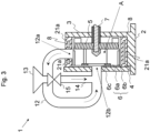
- a jacket structure (a first jacket 21a) is applied to the inside of members (the rear cover 3, the front cover 4, and the collision ring 8) surrounding the impact chamber A, and a jacket structure with a double pipe structure (not illustrated) is applied to the circulation circuit 12, and a refrigerant such as cooling water may flow in the jacket structure.
- Figs. 3 and 4 illustrate examples in which the jacket structure (the first jacket 21a) is provided in the collision ring 8.
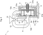
- a refrigerant passage (a second jacket 21b) is formed in the rotor 5 and the fixing portion 6a of the impact pin 6 fixed to the rotor 5, and refrigerant such as cooling water may flow in the refrigerant passage (see Figs. 4 and 5 ).
- the rotating shaft 7 has a hollow structure, and a cylindrical water pipe 7a is inserted in the rotating shaft 7, and a gap between the rotating shaft 7 and the water pipe 7a is a discharge channel 7b.
- a ring-shaped space (circulating water channel) and a space (a water channel and a discharge channel) are provided in the rotor 5.
- the ring-shaped space is formed in an outer peripheral portion (a portion contacting with a passage of the fixing portion 6a) of the rotor 5 around a rotating shaft.
- the space is, for example two pairs and four channels, and is formed perpendicular to the rotating shaft and extends in a radial direction to the ring-shape space.
- One end of the water channel communicates with the water pipe 7a via an opening of the rotating shaft 7.
- One end of the discharge channel communicates with the discharge channel 7b via another opening of the rotating shaft 7.
- a circulating water channel as illustrated in Figs. 4 and 5 is provided in the fixing portion 6a.
- a water channel of a refrigerant is formed as follows: the water pipe 7a ⁇ the water channel in the rotor 5 ⁇ the circulating water channel in the rotor 5 ⁇ the circulating water channel in the fixing portion 6a ⁇ the circulating water channel in the rotor 5 ⁇ the discharge channel in the rotor 5 ⁇ the discharge channel 7b.
- the second jacket 21b is used. Therefore, by providing a cooling mechanism also in the fixing portion 6a of the impact pin 6 in addition to the rotor 5, in comparison with the case where the cooling mechanism is not provided in the fixing portion 6a, there is merit to easily perform the control for suppressing an increase in the ambient temperature in the impact chamber A and the circulation circuit 12.
- a surface modification procedure of solid particles using the powder processing apparatus 1 according to the first embodiment will be described in an example in which fine particles are fixed on surfaces of core particles.
- the rotor 5 in which the detachable portion 6b is fixed to the fixing portion 6a is attached to the rotating shaft 7 and fixed by a nut, and the front cover 4 is closed.
- a refrigerant for example cooling water, is flowed in the first jacket 21a and the second jacket 21b at a constant flow.
- the supply port opening/closing valve 15 provided in the midstream of the material supply chute 14 is closed, and the discharge port opening/closing valve 9 of the modified powder discharge port is also closed.
- the rotating shaft 7 is rotated by a driving means (not illustrated) and, for example, the rotor 5 is rotated at a peripheral speed of approximately 80 m/sec.
- rapid air flow is generated in association with rotation of the impact pin 6.
- circulating flow is formed from the inlet 12a opening at the part of the collision ring 8 to the impact chamber A, via the circulation circuit 12 and the outlet 12b opening at the position facing the center of the rotor 5 in the front cover 4. In other words, perfect self circulating flow is formed.
- a circulating air volume per unit time generated in this case is remarkably large in comparison with a total volume of an impact chamber and a circulating system. Therefore, enormously frequent air circulation cycles can be formed in a short time.
- the supply port opening/closing valve 15 After the circulating flow is formed, when the supply port opening/closing valve 15 is opened, and mixed powder of core particles and fine particles is put into the material hopper 13 via the material weighing feeder 20, the mixed powder enters into the impact chamber A via the material hopper 13 and the material supply chute 14. After that, the supply port opening/closing valve 15 is closed.
- the mixed powder introduced in the impact chamber A receives a momentary striking action by the impact pin 6 provided to the rotor 5 rotating in the impact chamber A at a high speed, and further the mixed powder collides with the peripheral collision ring 8. Then, the mixed powder again returns to the impact chamber A with the circulation air flow through the circulation circuit 12, and again receives a similar striking action.
- uniform fixing process fixing of fine particles on surfaces of core particles
- composite particles in which fine particles are firmly fixed on surfaces of core particles are obtained.
- the discharge port opening/closing valve 9 of the modified powder discharge port is moved and is opened, and the composite particles are discharged.
- the composite particles are discharged by centrifugal force acting on the composite particles themselves and are collected by the powder collector 18 via the modified powder discharge pipe 17.
- the powder processing apparatus 1 is a batch type apparatus.
- a quantity of the mixed powder to be processed in one batch operation is determined by a volume between an outermost raceway surface (of the detachable portion 6b) of the impact pin 6 in the impact chamber A and the collision ring 8, and is more specifically determined by a distance (clearance) between an outermost raceway surface of the impact pin 6 and the collision ring 8.
- a load current value is not significantly increased.
- the load current value is rapidly increased, and ambient temperature in the impact chamber is increased. Therefore, for example, in the case where toner particles weak to heat is processed, the toner particles might be melted and adhered to the impact pin 6, the collision ring 8, and an inner surface of the circulation circuit 12, and the quality of the toner particles might be deteriorated.
- an impact force to be applied to mixed powder is basically determined by a rotation speed of the rotor 5 (a peripheral speed on an outermost raceway surface of the impact pin 6).
- a rotation speed of the rotor 5 a peripheral speed on an outermost raceway surface of the impact pin 6
- a process state of powder to be processed differs depending on physical properties of each powder to be processed. Therefore, operation conditions need to be balanced in accordance with the physical properties of each powder to be processed and an object of processing.
- a similar operation is performed by changing throughput (a quantity to be prepared in one batch operation) and a process time of mixed powder, and attaching the detachable portions 6b having different lengths in height direction. Accordingly, optimum operation conditions are found by confirming a change (whether there is a change in quality) in a process state and physical properties of composite particles, a change in ambient temperature in the impact chamber A, and also whether the composite particles (or core particles and fine particles which are raw materials therefor) are adhered to the impact pin 6, the rotor 5, the collision ring 8, and an inner surface of the circulation circuit 12.
- a distance (clearance) between an outermost raceway surface of the impact pin 6 and the collision ring 8 can be adjusted. Therefore, operation conditions can be easily found in which such as ambient temperature in an impact chamber is balanced with physical properties of powder to be processed.
- the detachable portions 6b having the same height sizes are not necessarily attached to every fixing portions 6a.
- the impact pin 6 may include both of the fixing portion 6a in which the detachable portion 6b having a long length in a height direction is attached and the fixing portion 6a in which the detachable portion 6b having a short length in a height direction is attached.
- the detachable portions 6b having the same lengths in a height direction are preferably attached to the fixing portions 6a positioned point-symmetrically.
- a tip portion of the impact pin 6 (a portion near a collision ring 8) is easy to be abraded.
- the abraded portion is configured by the detachable portion 6b detachable from the fixing portion 6a fixed to the rotor 5, and therefore only the abraded portion can be replaced.
- wear and abrasion resistance can be improved by using ceramics or a hard metal in a material of the detachable portion 6b.
- the detachable portion 6b is attached to the fixing portion 6a by engaging the engaging portion 6b2 to the groove 6a2. Therefore, at least, it is prevented that the detachable portion 6b is detached in a radial direction.
- a part of the members included in the impact pin 6 (the detachable portion 6b) is detachably attached to the other (the fixing portion 6a), and multiple types of the detachable portions 6b having different lengths in a height direction are prepared to adjust a distance between the impact pin 6 and the collision ring 8.
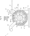
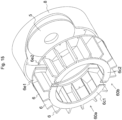
- a second embodiment is considered in which an impact pin group integrating multiple impact pins 6 is detachably attached to the rotor 5, and multiple types of the impact pin groups in which the impact pins have different lengths in a height direction are prepared to adjust a distance between the impact pin 6 and the collision ring 8 ( Figs. 10 to 13 ).
- an impact pin group is formed in which an end of the impact pin 6 on a side facing the rotor 5 is fixed to an impact pin fixing ring 6e, and the impact pin fixing ring 6e is detachably attached on a front surface of the rotor 5.
- Multiple types of the impact pin groups are prepared in which the impact pins 6 are fixed to the impact pin fixing ring 6e and have different radial lengths.
- an end portion of the impact pin 6 on a side opposite to a side fixed to the impact pin fixing ring 6e is preferably fixed to the fixing ring 6c.
- a passage of a refrigerant (the second jacket 21b) is formed only in an inside of a disc of the rotor 5.
- the impact pin fixing ring 6e is attached to the rotor 5 by screwing in an axial direction parallel to the rotating shaft 7 and firmly fixed since a large screw can be used in comparison with the first embodiment in which the detachable portion 6b is attached to the fixing portion 6a by screwing in a radial direction.
- a front surface of the rotor 5 is preferably formed in a disc-shaped projected portion in which an inner diameter of the impact pin fixing ring 6e is an outer diameter and which has the same thickness as the impact pin fixing ring 6e.
- the projected portion and a round notch at a center of the impact pin fixing ring 6e has a spigot structure, and the both of them can be fixed and positioned easily.
- one impact pin group in which every impact pins 6 are integrated by being fixed to the impact pin fixing ring 6e can be attached to and detached from the rotor 5 in a state in which the rotor 5 is attached to the rotating shaft 7. Therefore, attachment/detachment can be easily operated in comparison with the first embodiment in which each detachable portion 6b is attached to each fixing portion 6a after the rotor 5 is detached from the rotating shaft 7.
- the impact pin group may integrate the impact pins 6 by including both of the impact pins 6 having long lengths in a height direction and the impact pins 6 having short lengths in a height direction and fixing them to the impact pin fixing ring 6e.
- the rotor 5 rotates at a high speed. Therefore, a static balance and a dynamic balance need to be kept to minimize vibration of an apparatus.
- the detachable portion 6b needs to be attached to the same fixing portion 6a as before in the case where the same detachable portion 6b is again used after once being detached. Therefore, parts can be easily managed and handled in the second embodiment in which every impact pins 6 are integrally fixed to the impact pin fixing ring 6e.
- an impact pin group in which every impact pins 6 are fixed to the impact pin fixing ring 6e becomes heavy, and attachment to and detachment from the rotor 5 might become difficult.
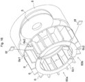
- multiple impact pin groups are formed in which the impact pins 6 are dividedly fixed to an impact pin fixing member in which the impact pin fixing ring 6e is divided into two or three, and the multiple impact pin groups may be attached to the rotor 5 (see Figs. 14 and 15 ).
- Fig. 14 illustrates an example of the impact pin group having two-divided structure (a first impact pin group 60a and a second impact pin group 60b) .
- the fixing ring 6c and the impact pin fixing ring 6e have a divided structure.
- a member on a side of the first impact pin group 60a of the fixing ring 6c is a first fixing ring member 6c1.
- a member on a side of the second impact pin group 60b is a second fixing ring member 6c2.
- a member on a side of the first impact pin group 60a of the impact pin fixing ring 6e is a first impact pin fixing ring member 6e1.
- a member on a side of the second impact pin group 60b is a second impact pin fixing ring member 6e2.
- the first fixing ring member 6c1 and the second fixing ring member 6c2 are detachably fixed such as by screwing with a covering plate 6f at a portion contacting each other (a bolt and a nut of a screw member are not illustrated).
- a part of the contact portions of the first fixing ring member 6c1 and the second fixing ring member 6c2 may be overlapped in an axial direction without using the covering plate 6f, and the overlapped portion may be screwed (see Fig. 15 , a screw member is not illustrated).
- Fig. 15 illustrates an example in which contact portions of the first impact pin fixing ring member 6e1 and the second impact pin fixing ring member 6e2 also have an overlapped shape.
- a contacting portion (the first fixing ring member 6c1 and the second fixing ring member 6c2, the first impact pin fixing ring member 6e1 and the second impact pin fixing ring member 6e2) may have a shape capable of interdigitating (for example, a shape cut in a zigzag shape and a shape cut in an uneven shape) (see Fig. 16 , and a screw member is not illustrated).
- sectional surface configuration views in Figs. 3 , 4 , 5 , and 11 illustrate the impact pins 6 viewed in front, and the impact pins 6 positioned on a back side are omitted.
- sectional surface configuration views in Figs. 3 , 4 , and 11 are illustrated so that the inlet 12a can be viewed to indicate circulating flow in the circulation circuit 12.
- the inlet 12a is positioned at a deep position from a sectional surface.
- the modified powder discharge port, the outlet 12b, and the first jacket 21a are omitted.
Landscapes
- Engineering & Computer Science (AREA)
- Food Science & Technology (AREA)
- Crushing And Pulverization Processes (AREA)
- Chemical & Material Sciences (AREA)
- Glanulating (AREA)
- Organic Chemistry (AREA)
- Chemical Kinetics & Catalysis (AREA)
Applications Claiming Priority (2)
| Application Number | Priority Date | Filing Date | Title |
|---|---|---|---|
| JP2013129339 | 2013-06-20 | ||
| PCT/JP2014/003111 WO2014203497A1 (ja) | 2013-06-20 | 2014-06-11 | 粉体処理装置 |
Publications (4)
| Publication Number | Publication Date |
|---|---|
| EP3012016A1 EP3012016A1 (en) | 2016-04-27 |
| EP3012016A4 EP3012016A4 (en) | 2018-01-03 |
| EP3012016C0 EP3012016C0 (en) | 2025-01-15 |
| EP3012016B1 true EP3012016B1 (en) | 2025-01-15 |
Family
ID=52104249
Family Applications (1)
| Application Number | Title | Priority Date | Filing Date |
|---|---|---|---|
| EP14813160.0A Active EP3012016B1 (en) | 2013-06-20 | 2014-06-11 | Powder-processing device |
Country Status (6)
| Country | Link |
|---|---|
| US (1) | US20160096181A1 (pl) |
| EP (1) | EP3012016B1 (pl) |
| JP (1) | JP5797358B2 (pl) |
| KR (1) | KR101609526B1 (pl) |
| PL (1) | PL3012016T3 (pl) |
| WO (1) | WO2014203497A1 (pl) |
Families Citing this family (2)
| Publication number | Priority date | Publication date | Assignee | Title |
|---|---|---|---|---|
| CN107694135B (zh) * | 2017-11-13 | 2021-09-14 | 昆明特康科技有限公司 | 一种用于高湿高黏性物料干燥制粉的磨机及其运用方法 |
| CN108187869B (zh) * | 2018-02-11 | 2024-09-20 | 北京石研科技有限公司 | 一种离心碰撞粉碎机 |
Family Cites Families (25)
| Publication number | Priority date | Publication date | Assignee | Title |
|---|---|---|---|---|
| US1212991A (en) * | 1911-10-20 | 1917-01-16 | Allis Chalmers Mfg Co | Impact-pulverizer. |
| US2609995A (en) * | 1948-05-07 | 1952-09-09 | Ernest Markus | Centrifugal mill |
| US2634915A (en) * | 1950-08-12 | 1953-04-14 | Paramount Mining And Milling C | Centrifugal impact pulverizing apparatus |
| USRE32355E (en) * | 1980-06-16 | 1987-02-17 | Portec, Inc. | Impeller shoe assembly |
| JPS5853227U (ja) * | 1981-10-02 | 1983-04-11 | 大阪瓦斯株式会社 | パグミルミキサ−の撹拌腕具 |
| CH658802A5 (en) * | 1982-11-08 | 1986-12-15 | Buehler Ag Geb | Agitator mill |
| JPS61283361A (ja) * | 1985-06-05 | 1986-12-13 | 株式会社 奈良機械製作所 | 衝撃粉砕機 |
| DE3687219T2 (de) * | 1985-10-07 | 1993-04-08 | Nara Machinery Co Ltd | Methode zur verbesserung der oberflaechenqualitaet von festen teilchen und vorrichtung dazu. |
| IT1216574B (it) * | 1988-04-14 | 1990-03-08 | Pozzato Alberto Breganze Vicen | Mulino a martelli, per la frantumazione di minerali e simili. |
| JPH0618580Y2 (ja) * | 1990-08-24 | 1994-05-18 | 株式会社奈良機械製作所 | 固体粒子の表面改質装置に用いる回転盤 |
| JP2941081B2 (ja) * | 1991-03-26 | 1999-08-25 | 株式会社奈良機械製作所 | 結晶性有機化合物の非晶質割合の増加と再結晶化を抑制する方法 |
| JP3053972B2 (ja) | 1992-08-07 | 2000-06-19 | 株式会社奈良機械製作所 | 粉体処理装置 |
| JPH08131818A (ja) * | 1994-11-11 | 1996-05-28 | Nara Kikai Seisakusho:Kk | 粉体処理装置 |
| US6325306B1 (en) * | 1997-10-22 | 2001-12-04 | Material Recovery Of North America, Inc. | Variable size reduction apparatus and process |
| JPH11216381A (ja) * | 1998-02-02 | 1999-08-10 | Canon Inc | 固体粒子の表面の処理装置及びトナー粒子の表面の処理方法 |
| US6443376B1 (en) * | 1999-12-15 | 2002-09-03 | Hosokawa Micron Powder Systems | Apparatus for pulverizing and drying particulate matter |
| US7055770B2 (en) * | 2000-05-08 | 2006-06-06 | Morbark, Inc. | Reducing machine rotor assembly and methods of constructing and operating the same |
| ES2292035T3 (es) * | 2000-10-02 | 2008-03-01 | Pangborn Corporation | Rueda de lanzamiento abrasiva y conjunto de cuchilla para la misma. |
| US7100855B2 (en) * | 2002-06-27 | 2006-09-05 | Barclay Roto-Shred Incorporated | Modular blades for tire shredder |
| NZ532007A (en) * | 2004-03-29 | 2006-11-30 | Rodney Warwick Sharp | Improvements in load transference in grinding discs |
| US7536760B2 (en) * | 2005-05-19 | 2009-05-26 | Nkg Co., Ltd. | Rotary cutting apparatus |
| US7357342B2 (en) * | 2005-09-23 | 2008-04-15 | Riley Power, Inc. | Split fan wheel and split shroud assemblies and methods of manufacturing and assembling the same |
| EP2377618A1 (en) * | 2010-04-14 | 2011-10-19 | Air Products And Chemicals, Inc. | Rotary impact mill |
| CN102933303B (zh) * | 2010-05-06 | 2015-02-04 | 细川密克朗集团股份有限公司 | 粉碎装置 |
| JP5377436B2 (ja) * | 2010-07-28 | 2013-12-25 | 株式会社奈良機械製作所 | 粉体処理装置 |
-
2014
- 2014-06-11 EP EP14813160.0A patent/EP3012016B1/en active Active
- 2014-06-11 WO PCT/JP2014/003111 patent/WO2014203497A1/ja not_active Ceased
- 2014-06-11 JP JP2015522545A patent/JP5797358B2/ja active Active
- 2014-06-11 KR KR1020157035238A patent/KR101609526B1/ko active Active
- 2014-06-11 PL PL14813160.0T patent/PL3012016T3/pl unknown
-
2015
- 2015-12-14 US US14/967,743 patent/US20160096181A1/en not_active Abandoned
Also Published As
| Publication number | Publication date |
|---|---|
| WO2014203497A1 (ja) | 2014-12-24 |
| KR101609526B1 (ko) | 2016-04-05 |
| PL3012016T3 (pl) | 2025-03-31 |
| US20160096181A1 (en) | 2016-04-07 |
| JPWO2014203497A1 (ja) | 2017-02-23 |
| JP5797358B2 (ja) | 2015-10-21 |
| EP3012016C0 (en) | 2025-01-15 |
| EP3012016A1 (en) | 2016-04-27 |
| KR20150145270A (ko) | 2015-12-29 |
| EP3012016A4 (en) | 2018-01-03 |
Similar Documents
| Publication | Publication Date | Title |
|---|---|---|
| RU2555915C2 (ru) | Динамический элемент для разделительного узла шаровой мельницы с мешалкой | |
| US8893993B2 (en) | Methods for pulverizing materials | |
| US8480016B2 (en) | Device for processing feedstock | |
| EP2789392B1 (en) | Horizontal dry mill | |
| EP2377618A1 (en) | Rotary impact mill | |
| EP3012016B1 (en) | Powder-processing device | |
| US20130034399A1 (en) | Throw away type rotary cutting apparatus and tip holder | |
| US20080080942A1 (en) | Dynamic balancing ring for cutter holder | |
| US8336797B2 (en) | Powder and granular material crushing and sizing apparatus | |
| JP4891574B2 (ja) | 粉砕装置およびこの粉砕装置を用いた粉体製造方法 | |
| CN112657609B (zh) | 用于碾碎能倾倒的给送料的设备 | |
| US6663030B2 (en) | Replaceable grate device for maximizing the throughput of solid material in ore mills | |
| EP1607138B1 (en) | Powder particle disintegrating and sizing apparatus | |
| JP2018051420A (ja) | 粉砕装置用ハンマ及びそれを備えた粉砕装置 | |
| US7854407B2 (en) | Low-profile housing for an impact crushing apparatus | |
| US9067211B2 (en) | Abrasive roll assembly | |
| US20020033425A1 (en) | Linersegment locator/retainr for ore grinding mills | |
| CN109906117B (zh) | 超细粉碎机 | |
| US9644683B2 (en) | Thermal management of bearings in hot magnetic separator | |
| US20120132736A1 (en) | Silicon metal grinding machine | |
| KR100787643B1 (ko) | 수직형 밀 및 그 분쇄면 형상결정방법 | |
| CN106964426A (zh) | 一种磨片及磨粉机 | |
| CN112969537A (zh) | 环缝磨 | |
| CN221086378U (zh) | 一种耐磨钢球分类装置 | |
| JP2010227862A (ja) | 粉砕機 |
Legal Events
| Date | Code | Title | Description |
|---|---|---|---|
| PUAI | Public reference made under article 153(3) epc to a published international application that has entered the european phase |
Free format text: ORIGINAL CODE: 0009012 |
|
| 17P | Request for examination filed |
Effective date: 20160114 |
|
| AK | Designated contracting states |
Kind code of ref document: A1 Designated state(s): AL AT BE BG CH CY CZ DE DK EE ES FI FR GB GR HR HU IE IS IT LI LT LU LV MC MK MT NL NO PL PT RO RS SE SI SK SM TR |
|
| AX | Request for extension of the european patent |
Extension state: BA ME |
|
| DAX | Request for extension of the european patent (deleted) | ||
| RIC1 | Information provided on ipc code assigned before grant |
Ipc: B01F 13/10 20060101ALI20170921BHEP Ipc: B01F 7/04 20060101ALI20170921BHEP Ipc: B02C 13/10 20060101AFI20170921BHEP Ipc: B02C 13/26 20060101ALI20170921BHEP Ipc: B02C 13/28 20060101ALI20170921BHEP |
|
| A4 | Supplementary search report drawn up and despatched |
Effective date: 20171205 |
|
| RIC1 | Information provided on ipc code assigned before grant |
Ipc: B02C 13/26 20060101ALI20171129BHEP Ipc: B02C 13/10 20060101AFI20171129BHEP Ipc: B01F 13/10 20060101ALI20171129BHEP Ipc: B01F 7/04 20060101ALI20171129BHEP Ipc: B02C 13/28 20060101ALI20171129BHEP |
|
| STAA | Information on the status of an ep patent application or granted ep patent |
Free format text: STATUS: EXAMINATION IS IN PROGRESS |
|
| 17Q | First examination report despatched |
Effective date: 20181025 |
|
| REG | Reference to a national code |
Ref country code: DE Ref legal event code: R079 Free format text: PREVIOUS MAIN CLASS: B01J0002000000 Ipc: B02C0013100000 Ref country code: DE Ref legal event code: R079 Ref document number: 602014091450 Country of ref document: DE Free format text: PREVIOUS MAIN CLASS: B01J0002000000 Ipc: B02C0013100000 |
|
| GRAP | Despatch of communication of intention to grant a patent |
Free format text: ORIGINAL CODE: EPIDOSNIGR1 |
|
| STAA | Information on the status of an ep patent application or granted ep patent |
Free format text: STATUS: GRANT OF PATENT IS INTENDED |
|
| RIC1 | Information provided on ipc code assigned before grant |
Ipc: B02C 13/28 20060101ALI20240819BHEP Ipc: B02C 13/26 20060101ALI20240819BHEP Ipc: B02C 13/10 20060101AFI20240819BHEP |
|
| INTG | Intention to grant announced |
Effective date: 20240903 |
|
| GRAS | Grant fee paid |
Free format text: ORIGINAL CODE: EPIDOSNIGR3 |
|
| GRAA | (expected) grant |
Free format text: ORIGINAL CODE: 0009210 |
|
| STAA | Information on the status of an ep patent application or granted ep patent |
Free format text: STATUS: THE PATENT HAS BEEN GRANTED |
|
| AK | Designated contracting states |
Kind code of ref document: B1 Designated state(s): AL AT BE BG CH CY CZ DE DK EE ES FI FR GB GR HR HU IE IS IT LI LT LU LV MC MK MT NL NO PL PT RO RS SE SI SK SM TR |
|
| REG | Reference to a national code |
Ref country code: CH Ref legal event code: EP Ref country code: GB Ref legal event code: FG4D |
|
| REG | Reference to a national code |
Ref country code: DE Ref legal event code: R096 Ref document number: 602014091450 Country of ref document: DE |
|
| REG | Reference to a national code |
Ref country code: IE Ref legal event code: FG4D |
|
| U01 | Request for unitary effect filed |
Effective date: 20250210 |
|
| U07 | Unitary effect registered |
Designated state(s): AT BE BG DE DK EE FI FR IT LT LU LV MT NL PT RO SE SI Effective date: 20250214 |
|
| PG25 | Lapsed in a contracting state [announced via postgrant information from national office to epo] |
Ref country code: RS Free format text: LAPSE BECAUSE OF FAILURE TO SUBMIT A TRANSLATION OF THE DESCRIPTION OR TO PAY THE FEE WITHIN THE PRESCRIBED TIME-LIMIT Effective date: 20250415 |
|
| PGFP | Annual fee paid to national office [announced via postgrant information from national office to epo] |
Ref country code: PL Payment date: 20250602 Year of fee payment: 12 |
|
| PG25 | Lapsed in a contracting state [announced via postgrant information from national office to epo] |
Ref country code: ES Free format text: LAPSE BECAUSE OF FAILURE TO SUBMIT A TRANSLATION OF THE DESCRIPTION OR TO PAY THE FEE WITHIN THE PRESCRIBED TIME-LIMIT Effective date: 20250115 |
|
| PGFP | Annual fee paid to national office [announced via postgrant information from national office to epo] |
Ref country code: GB Payment date: 20250618 Year of fee payment: 12 |
|
| PG25 | Lapsed in a contracting state [announced via postgrant information from national office to epo] |
Ref country code: IS Free format text: LAPSE BECAUSE OF FAILURE TO SUBMIT A TRANSLATION OF THE DESCRIPTION OR TO PAY THE FEE WITHIN THE PRESCRIBED TIME-LIMIT Effective date: 20250515 Ref country code: NO Free format text: LAPSE BECAUSE OF FAILURE TO SUBMIT A TRANSLATION OF THE DESCRIPTION OR TO PAY THE FEE WITHIN THE PRESCRIBED TIME-LIMIT Effective date: 20250415 |
|
| PG25 | Lapsed in a contracting state [announced via postgrant information from national office to epo] |
Ref country code: HR Free format text: LAPSE BECAUSE OF FAILURE TO SUBMIT A TRANSLATION OF THE DESCRIPTION OR TO PAY THE FEE WITHIN THE PRESCRIBED TIME-LIMIT Effective date: 20250115 |
|
| PG25 | Lapsed in a contracting state [announced via postgrant information from national office to epo] |
Ref country code: GR Free format text: LAPSE BECAUSE OF FAILURE TO SUBMIT A TRANSLATION OF THE DESCRIPTION OR TO PAY THE FEE WITHIN THE PRESCRIBED TIME-LIMIT Effective date: 20250416 |
|
| U20 | Renewal fee for the european patent with unitary effect paid |
Year of fee payment: 12 Effective date: 20250627 |
|
| PG25 | Lapsed in a contracting state [announced via postgrant information from national office to epo] |
Ref country code: SM Free format text: LAPSE BECAUSE OF FAILURE TO SUBMIT A TRANSLATION OF THE DESCRIPTION OR TO PAY THE FEE WITHIN THE PRESCRIBED TIME-LIMIT Effective date: 20250115 |
|
| PG25 | Lapsed in a contracting state [announced via postgrant information from national office to epo] |
Ref country code: CZ Free format text: LAPSE BECAUSE OF FAILURE TO SUBMIT A TRANSLATION OF THE DESCRIPTION OR TO PAY THE FEE WITHIN THE PRESCRIBED TIME-LIMIT Effective date: 20250115 |
|
| PG25 | Lapsed in a contracting state [announced via postgrant information from national office to epo] |
Ref country code: SK Free format text: LAPSE BECAUSE OF FAILURE TO SUBMIT A TRANSLATION OF THE DESCRIPTION OR TO PAY THE FEE WITHIN THE PRESCRIBED TIME-LIMIT Effective date: 20250115 |
|
| PLBE | No opposition filed within time limit |
Free format text: ORIGINAL CODE: 0009261 |
|
| STAA | Information on the status of an ep patent application or granted ep patent |
Free format text: STATUS: NO OPPOSITION FILED WITHIN TIME LIMIT |
|
| REG | Reference to a national code |
Ref country code: CH Ref legal event code: L10 Free format text: ST27 STATUS EVENT CODE: U-0-0-L10-L00 (AS PROVIDED BY THE NATIONAL OFFICE) Effective date: 20251126 |
|
| 26N | No opposition filed |
Effective date: 20251016 |
|
| REG | Reference to a national code |
Ref country code: CH Ref legal event code: H13 Free format text: ST27 STATUS EVENT CODE: U-0-0-H10-H13 (AS PROVIDED BY THE NATIONAL OFFICE) Effective date: 20260127 |
|
| PG25 | Lapsed in a contracting state [announced via postgrant information from national office to epo] |
Ref country code: MC Free format text: LAPSE BECAUSE OF FAILURE TO SUBMIT A TRANSLATION OF THE DESCRIPTION OR TO PAY THE FEE WITHIN THE PRESCRIBED TIME-LIMIT Effective date: 20250115 |