EP3011925A1 - Surgical instruments - Google Patents
Surgical instruments Download PDFInfo
- Publication number
- EP3011925A1 EP3011925A1 EP15178542.5A EP15178542A EP3011925A1 EP 3011925 A1 EP3011925 A1 EP 3011925A1 EP 15178542 A EP15178542 A EP 15178542A EP 3011925 A1 EP3011925 A1 EP 3011925A1
- Authority
- EP
- European Patent Office
- Prior art keywords
- end effector
- effector assembly
- knife
- elongated shaft
- pair
- Prior art date
- Legal status (The legal status is an assumption and is not a legal conclusion. Google has not performed a legal analysis and makes no representation as to the accuracy of the status listed.)
- Granted
Links
- 239000012636 effector Substances 0.000 claims abstract description 119
- 230000008878 coupling Effects 0.000 claims abstract description 47
- 238000010168 coupling process Methods 0.000 claims abstract description 47
- 238000005859 coupling reaction Methods 0.000 claims abstract description 47
- 238000000034 method Methods 0.000 claims description 10
- 230000005540 biological transmission Effects 0.000 description 11
- 230000000712 assembly Effects 0.000 description 5
- 238000000429 assembly Methods 0.000 description 5
- 238000007789 sealing Methods 0.000 description 4
- 238000013519 translation Methods 0.000 description 4
- 238000001356 surgical procedure Methods 0.000 description 3
- 230000006835 compression Effects 0.000 description 2
- 238000007906 compression Methods 0.000 description 2
- 238000012976 endoscopic surgical procedure Methods 0.000 description 2
- 239000000463 material Substances 0.000 description 2
- 238000012986 modification Methods 0.000 description 2
- 230000004048 modification Effects 0.000 description 2
- 239000000853 adhesive Substances 0.000 description 1
- 230000001070 adhesive effect Effects 0.000 description 1
- 210000004204 blood vessel Anatomy 0.000 description 1
- 238000004891 communication Methods 0.000 description 1
- 238000009429 electrical wiring Methods 0.000 description 1
- 230000002708 enhancing effect Effects 0.000 description 1
- 238000003780 insertion Methods 0.000 description 1
- 230000037431 insertion Effects 0.000 description 1
- 238000012830 laparoscopic surgical procedure Methods 0.000 description 1
- 230000013011 mating Effects 0.000 description 1
- 230000003278 mimic effect Effects 0.000 description 1
- 230000001954 sterilising effect Effects 0.000 description 1
- 238000004659 sterilization and disinfection Methods 0.000 description 1
Images



Classifications
-
- A—HUMAN NECESSITIES
- A61—MEDICAL OR VETERINARY SCIENCE; HYGIENE
- A61B—DIAGNOSIS; SURGERY; IDENTIFICATION
- A61B17/00—Surgical instruments, devices or methods
- A61B17/28—Surgical forceps
- A61B17/29—Forceps for use in minimally invasive surgery
- A61B17/295—Forceps for use in minimally invasive surgery combined with cutting implements
-
- A—HUMAN NECESSITIES
- A61—MEDICAL OR VETERINARY SCIENCE; HYGIENE
- A61B—DIAGNOSIS; SURGERY; IDENTIFICATION
- A61B18/00—Surgical instruments, devices or methods for transferring non-mechanical forms of energy to or from the body
- A61B18/04—Surgical instruments, devices or methods for transferring non-mechanical forms of energy to or from the body by heating
- A61B18/12—Surgical instruments, devices or methods for transferring non-mechanical forms of energy to or from the body by heating by passing a current through the tissue to be heated, e.g. high-frequency current
- A61B18/14—Probes or electrodes therefor
- A61B18/1442—Probes having pivoting end effectors, e.g. forceps
- A61B18/1445—Probes having pivoting end effectors, e.g. forceps at the distal end of a shaft, e.g. forceps or scissors at the end of a rigid rod
-
- A—HUMAN NECESSITIES
- A61—MEDICAL OR VETERINARY SCIENCE; HYGIENE
- A61B—DIAGNOSIS; SURGERY; IDENTIFICATION
- A61B17/00—Surgical instruments, devices or methods
- A61B2017/0046—Surgical instruments, devices or methods with a releasable handle; with handle and operating part separable
- A61B2017/00473—Distal part, e.g. tip or head
-
- A—HUMAN NECESSITIES
- A61—MEDICAL OR VETERINARY SCIENCE; HYGIENE
- A61B—DIAGNOSIS; SURGERY; IDENTIFICATION
- A61B17/00—Surgical instruments, devices or methods
- A61B17/28—Surgical forceps
- A61B17/29—Forceps for use in minimally invasive surgery
- A61B2017/2901—Details of shaft
- A61B2017/2908—Multiple segments connected by articulations
Definitions
- the present disclosure relates to surgical instruments.
- the present disclosure relates to a surgical instrument including a reusable handle and shaft assembly and a disposable end effector configured to be releasably coupled thereto.
- Endoscopic forceps are commonly used in endoscopic surgical procedures to coagulate, cauterize and seal tissue.
- Such forceps typically include a pair of jaw members that can be controlled by a surgeon to grasp targeted tissue, such as, e.g., a blood vessel. Utilizing a movable handle of the forceps, the jaw members may be approximated toward one another to apply a mechanical clamping force to the tissue.
- the jaw members are typically associated with one or more electrodes to permit the delivery of electrosurgical energy to the tissue. The combination of mechanical clamping force and electrosurgical energy has been demonstrated to fuse adjacent layers of tissue captured between the jaw members with limited demarcation therebetween.
- endoscopic forceps having a reusable handle and shaft assembly and a disposable end effector assembly that can be easily releasably coupled to the reusable handle and shaft assembly.
- distal refers to a portion of a surgical instrument, including an end effector, handle assembly and/or elongated shaft thereof, that is being described which is further from a user
- proximal refers to a portion of a surgical instrument, including an end effector, handle assembly and/or elongated shaft thereof, that is being described which is closer to a user.
- An aspect of the present disclosure provides an electrosurgical instrument, such as, for example, an endoscopic electrosurgical forceps.
- the forceps include a handle assembly or housing, an elongated shaft, a knife drive shaft, a jaw drive shaft, an end effector and a coupling member.
- the elongated shaft has a proximal end coupled to the housing and a distal end.
- the knife drive shaft is disposed within the housing and axially movable within the elongated shaft.
- the jaw drive shaft is disposed within the housing and axially movable within the elongated shaft.
- the end effector includes a pair of opposing jaw members, a knife member, and a driven member.
- the knife member has a proximal end and a distal end and is translatable through the jaw members.
- the proximal end is selectively engageable to a distal end of the knife drive shaft such that movement of the knife drive shaft moves the knife member.
- the driven member has proximal end distal ends.
- the proximal end is configured to operably couple to the jaw drive shaft and the distal end is configured to operably couple to the pair of jaw members such that movement of the driven member moves the pair of jaw members between an open configuration and a closed configuration.
- the coupling member is configured to releasably secure the end effector and the elongated shaft.
- the knife member may define an opening therein and the knife drive shaft may be rotatably engageable with the opening such that the end effector is rotatable about the knife drive shaft between an angled configuration with the elongated shaft and an aligned configuration with the elongated shaft.
- the knife member may rotatably engages an intermediate portion of the elongated shaft and the opening may be defined in a proximal end of the knife member.
- the opening may have an oblong configuration.
- the end effector may further include an outer cannulated shaft rotatably coupled to the pair of jaw members and may house a distal end of the knife member and the distal end of the driven member.
- a proximal end of the outer cannulated shaft may have a first pair of tabs extending laterally therefrom.
- the distal end of the elongated shaft may have a second pair of tabs extending laterally therefrom.
- the coupling member may include a pair of arms configured to overlap the first and second pairs of tabs such that the coupling member secures the elongated shaft and the end effector assembly upon engagement thereof.
- the knife member may include an elongated slot defined therein.
- the coupling member may be configured for snap fit engagement with the outer cannulated shaft and the distal end of the elongated shaft.
- the end effector may include a pair of electrical leads coupled to the pair of jaw members.
- the elongated shaft may have a pair of electrical leads extending from the distal end thereof configured for releasable electrical connection to the pair of electrical leads of the end effector.
- an embodiment of a disposable end effector includes a pair of opposing jaw members, a knife member, a driven member, and an outer cannulated shaft.
- the knife member has a proximal end and a distal end.
- the knife member is translatable through at least one jaw member.
- the proximal end of the knife member is selectively engageable to a distal end of a knife drive shaft.
- the knife member includes an opening defined in the proximal end thereof.
- the driven member has a distal end configured to operably couple to the pair of jaw members such that movement of the driven member moves the pair of jaw members between an open configuration and a closed configuration.
- the outer cannulated shaft is rotatably coupled to the pair of jaw members that houses the distal end of the knife member and the distal end of the driven member.
- a method of assembling an electrosurgical instrument includes providing a housing having an elongated shaft extending therefrom; coupling a knife member of an end effector assembly to a knife drive shaft operably coupled to the housing of the electrosurgical instrument; rotating the end effector assembly relative to the knife drive shaft into coaxial alignment with the elongated shaft of the electrosurgical instrument; engaging a driven member of the end effector assembly with a jaw drive shaft operably coupled to the housing and axially movable within the elongated shaft; and attaching a coupling member to the end effector assembly and the elongated shaft to couple the end effector assembly with the elongated shaft.
- rotating the end effector assembly may engage the driven member with the jaw drive shaft.
- a surgical instrument including a reusable housing or handle assembly, an elongated shaft coupled to the handle assembly, and a disposable end effector assembly releasably coupleable to the elongated shaft may prove useful in the surgical arena, and such a surgical instrument is described herein.
- an electrosurgical instrument such as, for example, electrosurgical forceps 10 generally includes a reusable housing or handle assembly 12 having a reusable elongated shaft 114 extending distally therefrom and a disposable end effector assembly 200 releasably coupled to a distal end 134 thereof.
- Handle assembly 12 supports various actuators thereon for remotely controlling end effector assembly 200 through elongated shaft 114.
- this configuration is typically associated with instruments for use in laparoscopic or endoscopic surgical procedures, various aspects of the present disclosure may be practiced with traditional open instruments and in connection with endoluminal procedures as well.
- handle assembly 12 supports a stationary handle 20, a movable handle 22, a trigger 24 and a rotation knob 26.
- the movable handle 22 is operable to move the end effector assembly 200 between an open configuration ( FIG. 5A ) wherein a pair of opposed jaw members 202a, 202b are disposed in spaced relation relative to one another, and a closed configuration ( FIG. 5B ) wherein jaw members 202a, 202b are approximated. Compression of the movable handle 22 relative to the stationary handle 20 moves the end effector assembly 200 to the closed configuration and release of the movable handle 22 from the stationary handle 20 moves the end effector assembly 200 to the open configuration.
- the trigger 24 is selectively operable to extend and retract a knife member 220 (see FIG. 3 ) through the end effector assembly 200 when the end effector assembly 200 is in the closed configuration.
- Actuation of the rotation knob 26 rotates elongated shaft 114 and end effector assembly 200 about a longitudinal axis "X" extending through forceps 10 (See FIG. 1 ).
- handle assembly 12 supports a depressible switch 19 thereon, which is operable by the user to initiate and terminate the delivery of electrosurgical energy (e.g., RF energy) to the end effector assembly 200.
- the switch 19 is in electrical communication with an electrosurgical generator (not shown) via suitable electrical wiring (not shown) extending from handle assembly 12.
- electrosurgical generator not shown
- end effector assembly 200 may be battery-powered.
- the switch 19 may be any suitable switch capable of electrically coupling the generator to the end effector assembly 200.
- elongated shaft 114 has a proximal end 132 and a distal end 134 and defines the longitudinal axis "X" therebetween.
- Elongated shaft 114 defines an elongated cavity 136 therein configured to house the internal components thereof, such as, for example, a knife drive shaft 140 and a jaw drive shaft 160.
- Elongated shaft 114 may include a cover 138 ( FIG. 9 ) rotatably engaged thereto that covers cavity 136 during use of electrosurgical instrument 10.
- Proximal end 132 of elongated shaft 114 is coupled to handle assembly 12 and distal end 134 of elongated shaft 114 is configured to releasably couple to a proximal end 210a of the end effector assembly 200 shown in FIG. 6 via a coupling member 260, as described in greater detail below.
- Proximal ends 204a, 204b of each jaw member 202a, 202b include an electrical lead 212 extending proximally therefrom and configured to mate with a corresponding electrical element of the elongated shaft 114.
- the electrical connection is made at a junction "J" ( FIG. 5A ) at which tabs 139a, 239a come together.
- One electrical lead 212 may be routed and electrically connected to a conductive pad on each tab 239a.
- elongated shaft 114 includes knife drive shaft 140 and jaw drive shaft 160 each being axially movable within elongated shaft 114 and along longitudinal axis "X.”
- knife drive shaft 140 has a proximal end 140a and a distal end 140b.
- Proximal end 140a of knife drive shaft 140 is operably coupled to handle assembly 12 such that an actuation of trigger 24 axially moves knife drive shaft 140 distally through elongated shaft 114.
- Distal end 140b of knife drive shaft 140 is configured for pivotable engagement with a knife member 220 of end effector assembly 200.
- distal end 140b of knife drive shaft 140 includes a surface feature, such as, for example, a rounded projection 142.
- Projection 142 is disposed within an intermediate portion 133 of elongated shaft 114, spaced a predefined distance from distal end 134 of elongated shaft 114.
- Projection 142 is configured for disposal in an opening 222 defined in a proximal end 220a of knife member 220, as described in greater detail below, such that knife drive shaft 140 can selectively engage and drive axial movement of knife member 220 upon actuation of trigger 24 (see FIG. 7 ).
- jaw drive shaft 160 includes a proximal end 160a and a distal end 160b.
- Proximal end 160a of jaw drive shaft 160 is operably coupled to handle assembly 12 such that an actuation of handle 22 relative to handle 20 axially moves jaw drive shaft 160 within elongated shaft 114 and along longitudinal axis "X.”
- Distal end 160b of jaw drive shaft 160 includes a connection portion 162 configured to releasably engage a proximal end 230a of a driven member 230 of end effector assembly 200.
- Connection portion 162 includes a pair of resiliently biased fingers 164a, 164b defining a cavity 166 therebetween.
- Cavity 166 is adapted for disposal of proximal end 230a of driven member 230 of end effector assembly 200.
- fingers 164a, 164b releasably capture proximal end 230a of driven member 230 to form a snap fit engagement between jaw drive shaft 160 and driven member 230.
- jaw drive shaft 160 and driven member 230 can be configured for various engagements, such as, for example, frictional, pull and lock, compression fit, or the like.
- the proximal end 230a of driven member 230 includes a t-shaped flange that is configured to be rotatingly received within cavity 166 as best shown in FIGS. 7 and 8 .
- jaw drive shaft 160 moves along longitudinal axis "X,” in a direction indicated by arrow “A” in FIG. 5A , via the operable coupling of jaw drive shaft 160 with handle assembly 12.
- the axial movement or translation of jaw drive shaft 160 within elongated shaft 114 drives concomitant axial movement of driven member 230 to move jaw members 202a, 202b of end effector assembly 200 from an open configuration, as shown in FIG. 5A , to a closed configuration, as shown in FIG. 5B , to clamp tissue disposed between jaw members 202a, 202b.
- electrosurgical forceps 10 further includes an outer cannulated shaft 210 attached to jaw members 202a, 202b.
- Proximal ends 204a, 204b of jaw members 202a, 202b each define a cam slot 206a, 206b adapted for sliding disposal of a pivot bar 208 of driven member 230 to open and close jaw members 202a, 202b upon translation of driven member 230 therethrough.
- jaw members 202a, 202b pivot about a pivot point "P" relative to one another to clamp tissue disposed therebetween.
- the upper and lower jaw members 202a, 202b include electrical leads 212a and 212b extending proximally therefrom.
- Tissue-engaging sealing plates 214a, 214b are disposed on the lower and upper jaw members 202a, 202b, respectively, and are electrically coupled to opposite terminals, e.g., positive or active (+) and negative or return (-) terminals associated with the generator.
- bipolar energy may be provided to the sealing plates 214a, 214b and through tissue.
- sealing plates 214a, 214b may be configured to deliver monopolar energy to tissue.
- one or both sealing plates 214a, 214b deliver electrosurgical energy from an active terminal, e.g., (+), while a return pad (not shown) is placed generally on a patient and provides a return path to the opposite terminal, e.g., (-), of the generator.
- an active terminal e.g., (+
- a return pad not shown
- end effector assembly 200 includes knife member 220, which extends between jaw members 202a, 202b and is axially movable or translatable between jaw members 202a, 202b.
- Knife member 220 has an elongated configuration and has a proximal end 220a and a distal end 220b.
- Proximal end 220a of knife member 220 defines an oblong opening 222 therein configured for rotatable receipt of projection 142 of knife drive shaft 140 as explained above.
- Opening 222 may be suitably configured, such as, for example, oval, rectangular, tapered, variable, uniform, non-uniform, and/or elongated.
- knife member 220 Upon insertion of projection 142 of knife drive shaft 140 within opening 222 of knife member 220, knife member 220 can be rotated relative to knife drive shaft 140 between a non-locking, angled configuration with elongated shaft 114, as shown in FIG. 7 , and a locking, aligned configuration with elongated shaft 114, as shown in FIG. 8 , as described in greater detail below.
- Distal end 220b of knife member 220 has a distal-most edge 224 that defines a sharp surface or blade 226 thereon configured to axially slice through tissue.
- Knife member 220 further defines an elongated slot 228 therein. It is contemplated that pivot bar 208, which drives the opening and closing of jaw members 202a, 202b about pivot point "P," extends through the elongated slot 228 such that knife member 220 can translate over pivot bar 208 between proximal and distal limits 228a, 228b of elongated slot 228.
- knife member 220 axially translates through elongated shaft 114 to displace blade 226 from a proximal position between jaw members 202a, 202b toward a distal position between jaw members 202a, 202b and to slice through tissue disposed between jaw members 202a, 202b.
- end effector assembly 200 includes driven member 230, which is configured to open and close jaw members 202a, 202b upon axial movement of jaw drive shaft 160.
- Driven member 230 has a proximal end 230a and a distal end 230b.
- Proximal end 230a of driven member 230 is configured to releasably engage connection portion 162 of jaw drive shaft 160 such that driven member 230 is movable by jaw drive shaft 160.
- Distal end 230b of driven member 230 is operably coupled to jaw members 202a, 202b such that axial movement of driven member 230, via axial translation of jaw drive shaft 160, moves or translates pivot bar 208 through cam slots 206a, 206b of jaw members 202a, 202b to open and close jaw members 202a, 202b.
- end effector assembly 200 further includes outer cannulated shaft 210, which houses distal end 220b of knife member 220 and distal end 230b of driven member 230.
- Cannulated shaft 210 has a proximal end 242a and a distal end 242b.
- proximal end 242a includes a pair of tabs 239a extending laterally therefrom. Tabs 239a abut against tabs 139a of elongated shaft 114 upon coupling of end effector assembly 200 with elongated shaft 114, as shown in FIGS. 5A and 5B .
- Distal end 242b of cannulated shaft 210 includes two pivot points "P" having jaw members 202a, 202b rotatably coupled therewith. Jaw members 202a, 202b pivot relative to one another about pivot points "P" of cannulated shaft 210.
- projection 142 of knife drive shaft 140 is inserted within opening 222 defined in proximal end 220a of knife member 220 and end effector assembly 200 is rotated, in a direction indicated by arrow "C" in FIG. 7 , through cavity 136 defined in elongated shaft 114 and toward a locking configuration with elongated shaft 114, in which end effector assembly 200 and elongated shaft 114 are in coaxial alignment, as shown in FIG. 8 .
- tabs 239a of end effector assembly 200 abut tabs 139a of elongated shaft 114 and proximal ends 220a, 230a of knife member 220 and driven member 230, respectively, are disposed within elongated shaft 114.
- end effector assembly 200 in the direction indicated by arrow "C," also couples proximal end 230a of driven member 230 with connection portion 162 of jaw drive shaft 160 to releasably fix driven member 230 with jaw drive shaft 160.
- a coupling member 260 is connected at the junction "J" of elongated shaft 114 and end effector assembly 200, as described in greater detail below.
- coupling member 260 releasably connects distal end 134 of elongated shaft 114 and proximal end 242a of end effector assembly 200.
- coupling member 260 includes a pair of spaced apart, parallel arms 262a, 262b extending from a top portion or hood 264 thereof. Arms 262a, 262b are spaced from one another a distance substantially equal to a width of distal end 134 of elongated shaft 114.
- Coupling member 260 may be fabricated from a material that allows arms 262a, 262b to flex relative to one another to fit securely (e.g., a snap fit engagement) around the junction "J" of elongated shaft 114 and end effector assembly 200.
- Arms 262a, 262b each have a flange 266a, 266b extending around perimeters thereof and toward and interior of coupling member 260.
- Flanges 266a, 266b are configured to extend underneath bottom portions of both elongated shaft 114 and end effector assembly 200 upon connection of coupling member 260 with junction "J.” Flanges 266a, 266b are also configured to overlap tabs 139a of elongated shaft 114 and tabs 239a of end effector assembly 200 to retain tabs 139a, 239a within coupling member 260 such that relative axial movement of elongated shaft 114 and end effector assembly 200 is resisted and/or prevented by coupling member 260.
- portions or an entirety of coupling member 260 can have various material properties, such as, for example, rigid, flexible, adhesive and/or memory shape. It is further contemplated that coupling member 260 generally has a squared configuration corresponding to a squared configuration of elongated shaft 114 and/or end effector assembly 200. In some embodiments, coupling member 260 may be suitably configured so as to correspond to various configurations of elongated shaft 114 and/or end effector assembly 200.
- arms 262a, 262b of coupling member 260 overlap tabs 139a, 239a of elongated shaft 114 and end effector assembly 200 to capture tabs 139a, 239a therein and releasably lock end effector assembly 200 to elongated shaft 114.
- surgical instrument 10 is assembled for use.
- cover 138 of elongated shaft 114 is moved to a closed position to cover cavity 136, thereby enclosing internal components of elongated shaft 114 to prevent exposure of the internal components to surgical debris.
- end effector assembly 200 may be disposed of and handle assembly 12 and elongated shaft 114 may be reused after sterilization.
- arms 262a, 262b of coupling member 260 are flexed outwardly to detach coupling member 260 from elongated shaft 114 and end effector assembly 200.
- End effector 200 is rotated, in a direction indicated by arrow "D" in FIG. 8 , which detaches driven member 230 from connection portion 162 of jaw drive shaft 160.
- Projection 142 of knife drive shaft 140 is released from opening 222 of knife member 220, thereby detaching end effector assembly 200 from elongated shaft 114. End effector assembly 200 is then discarded.
- the various embodiments disclosed herein may also be configured to work with robotic surgical systems and what is commonly referred to as "Telesurgery.”
- Such systems employ various robotic elements to assist the surgeon in the operating theatre and allow remote operation (or partial remote operation) of surgical instrumentation.
- Various robotic arms, gears, cams, pulleys, electric and mechanical motors, etc. may be employed for this purpose and may be designed with a robotic surgical system to assist the surgeon during the course of an operation or treatment.
- Such robotic systems may include remotely steerable systems, automatically flexible surgical systems, remotely flexible surgical systems, remotely articulating surgical systems, wireless surgical systems, modular or selectively configurable remotely operated surgical systems, etc.
- the transmission assemblies of the present disclosure may be configured for use with such robotic systems in addition to being used with manually-operated assemblies. That is, depending on the particular procedure, the transmission assembly may be coupled to a manually-operated assembly or a robotic system.
- the transmission assemblies of the present disclosure are capable of being used in either configuration without the need for multiple transmission assemblies depending on whether robotic or manual surgery is desired.
- the robotic system would include suitable components, such as those detailed above, capable of manipulating and actuating the transmission assembly.
- the robotic surgical systems may further be employed with one or more consoles that are next to the operating theater or located in a remote location.
- one team of surgeons or nurses may prep the patient for surgery and configure the robotic surgical system with one or more of the transmission assemblies while another surgeon (or group of surgeons) remotely control the transmission assembly(s) via the robotic surgical system.
- a highly skilled surgeon may perform multiple operations in multiple locations without leaving his/her remote console which can be both economically advantageous and a benefit to the patient or a series of patients.
- the robotic arms of the surgical system are typically coupled to a pair of master handles by a controller.
- the handles can be moved by the surgeon to produce a corresponding movement, manipulation, and/or actuation of the transmission assembly(s) coupled thereto.
- the movement of the master handles may be scaled so that the operably components of the transmission assembly(s) has a corresponding movement that is different, smaller or larger, than the movement performed by the operating hands of the surgeon.
- the scale factor or gearing ratio may be user-adjustable so that the operator can control the resolution of the operable components of the transmission assembly(s).
- the master handles of the robotic system may further include various sensors to provide feedback to the surgeon relating to various tissue parameters or conditions, e.g., tissue resistance due to manipulation, cutting or otherwise treating, pressure by the instrument onto the tissue, tissue temperature, tissue impedance, etc. As can be appreciated, such sensors provide the surgeon with enhanced tactile feedback simulating actual operating conditions.
- the master handles may also include a variety of different actuators for delicate tissue manipulation or treatment further enhancing the surgeon's ability to mimic actual operating conditions.
Landscapes
- Health & Medical Sciences (AREA)
- Life Sciences & Earth Sciences (AREA)
- Surgery (AREA)
- Engineering & Computer Science (AREA)
- Animal Behavior & Ethology (AREA)
- General Health & Medical Sciences (AREA)
- Biomedical Technology (AREA)
- Heart & Thoracic Surgery (AREA)
- Medical Informatics (AREA)
- Molecular Biology (AREA)
- Veterinary Medicine (AREA)
- Nuclear Medicine, Radiotherapy & Molecular Imaging (AREA)
- Public Health (AREA)
- Ophthalmology & Optometry (AREA)
- Physics & Mathematics (AREA)
- Plasma & Fusion (AREA)
- Otolaryngology (AREA)
- Surgical Instruments (AREA)
- Orthopedic Medicine & Surgery (AREA)
- Pathology (AREA)
Abstract
Description
- The present disclosure relates to surgical instruments. In particular, the present disclosure relates to a surgical instrument including a reusable handle and shaft assembly and a disposable end effector configured to be releasably coupled thereto.
- Endoscopic forceps are commonly used in endoscopic surgical procedures to coagulate, cauterize and seal tissue. Such forceps typically include a pair of jaw members that can be controlled by a surgeon to grasp targeted tissue, such as, e.g., a blood vessel. Utilizing a movable handle of the forceps, the jaw members may be approximated toward one another to apply a mechanical clamping force to the tissue. The jaw members are typically associated with one or more electrodes to permit the delivery of electrosurgical energy to the tissue. The combination of mechanical clamping force and electrosurgical energy has been demonstrated to fuse adjacent layers of tissue captured between the jaw members with limited demarcation therebetween.
- While this type of endoscopic forceps is suitable for its intended use, since it is typically disposable it is relatively expensive because it is not reusable after a surgical procedure.
- Accordingly, in view of at least the above drawbacks of wholly disposable endoscopic forceps, it would be desirable to construct endoscopic forceps having a reusable handle and shaft assembly and a disposable end effector assembly that can be easily releasably coupled to the reusable handle and shaft assembly.
- Embodiments of the present disclosure are described in detail with reference to the drawing figures wherein like reference numerals identify similar or identical elements. As used herein, the term "distal" refers to a portion of a surgical instrument, including an end effector, handle assembly and/or elongated shaft thereof, that is being described which is further from a user, while the term "proximal" refers to a portion of a surgical instrument, including an end effector, handle assembly and/or elongated shaft thereof, that is being described which is closer to a user.
- An aspect of the present disclosure provides an electrosurgical instrument, such as, for example, an endoscopic electrosurgical forceps. The forceps include a handle assembly or housing, an elongated shaft, a knife drive shaft, a jaw drive shaft, an end effector and a coupling member. The elongated shaft has a proximal end coupled to the housing and a distal end. The knife drive shaft is disposed within the housing and axially movable within the elongated shaft. The jaw drive shaft is disposed within the housing and axially movable within the elongated shaft. The end effector includes a pair of opposing jaw members, a knife member, and a driven member. The knife member has a proximal end and a distal end and is translatable through the jaw members. The proximal end is selectively engageable to a distal end of the knife drive shaft such that movement of the knife drive shaft moves the knife member. The driven member has proximal end distal ends. The proximal end is configured to operably couple to the jaw drive shaft and the distal end is configured to operably couple to the pair of jaw members such that movement of the driven member moves the pair of jaw members between an open configuration and a closed configuration. The coupling member is configured to releasably secure the end effector and the elongated shaft.
- In some embodiments, the knife member may define an opening therein and the knife drive shaft may be rotatably engageable with the opening such that the end effector is rotatable about the knife drive shaft between an angled configuration with the elongated shaft and an aligned configuration with the elongated shaft. The knife member may rotatably engages an intermediate portion of the elongated shaft and the opening may be defined in a proximal end of the knife member. The opening may have an oblong configuration.
- In some embodiments, the end effector may further include an outer cannulated shaft rotatably coupled to the pair of jaw members and may house a distal end of the knife member and the distal end of the driven member. A proximal end of the outer cannulated shaft may have a first pair of tabs extending laterally therefrom. The distal end of the elongated shaft may have a second pair of tabs extending laterally therefrom. Upon coupling the elongated shaft and the end effector, the first and second pairs of tabs may abut one another. The coupling member may include a pair of arms configured to overlap the first and second pairs of tabs such that the coupling member secures the elongated shaft and the end effector assembly upon engagement thereof. It is contemplated that the knife member may include an elongated slot defined therein. The coupling member may be configured for snap fit engagement with the outer cannulated shaft and the distal end of the elongated shaft.
- In some embodiments, the end effector may include a pair of electrical leads coupled to the pair of jaw members. The elongated shaft may have a pair of electrical leads extending from the distal end thereof configured for releasable electrical connection to the pair of electrical leads of the end effector.
- In another aspect of the present disclosure, an embodiment of a disposable end effector is disclosed. The end effector includes a pair of opposing jaw members, a knife member, a driven member, and an outer cannulated shaft. The knife member has a proximal end and a distal end. The knife member is translatable through at least one jaw member. The proximal end of the knife member is selectively engageable to a distal end of a knife drive shaft. The knife member includes an opening defined in the proximal end thereof. The driven member has a distal end configured to operably couple to the pair of jaw members such that movement of the driven member moves the pair of jaw members between an open configuration and a closed configuration. The outer cannulated shaft is rotatably coupled to the pair of jaw members that houses the distal end of the knife member and the distal end of the driven member.
- In yet another aspect of the present disclosure, a method of assembling an electrosurgical instrument is provided. The method includes providing a housing having an elongated shaft extending therefrom; coupling a knife member of an end effector assembly to a knife drive shaft operably coupled to the housing of the electrosurgical instrument; rotating the end effector assembly relative to the knife drive shaft into coaxial alignment with the elongated shaft of the electrosurgical instrument; engaging a driven member of the end effector assembly with a jaw drive shaft operably coupled to the housing and axially movable within the elongated shaft; and attaching a coupling member to the end effector assembly and the elongated shaft to couple the end effector assembly with the elongated shaft.
- In some embodiments, rotating the end effector assembly may engage the driven member with the jaw drive shaft.
- Various embodiments of the present disclosure are described hereinbelow with references to the drawings, wherein:
-
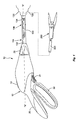
FIG. 1 is an elevation view, with parts separated, of an electrosurgical instrument with a selectively attachable end effector assembly according to an embodiment of the present disclosure; -
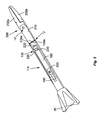
FIG. 2 is an enlarged, elevation view of the end effector assembly coupled to an elongated shaft of the electrosurgical instrument shown inFIG. 1 ; -
FIG. 3 is an enlarged, perspective view of the end effector assembly shown inFIG. 1 coupled to a knife drive shaft of the elongated shaft; -
FIG. 4 is an enlarged, side view of the end effector assembly ofFIG. 1 shown coupled to a jaw drive shaft of the elongated shaft; -
FIGS. 5A and5B are enlarged, perspective views of the elongated shaft and end effector assembly shown inFIG. 1 illustrating opening and closing of end effector assembly via movement of the jaw drive shaft shown inFIG. 4 ; -
FIG. 6 is an enlarged, perspective view of the end effector assembly shown inFIG. 1 ; -
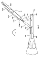
FIG. 7 is an enlarged, perspective view of the electrosurgical instrument shown inFIG. 1 illustrating a rotatable coupling of the end effector assembly with the elongated shaft; -
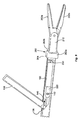
FIG. 8 is a plan view of a coupling member and the end effector assembly shown in position to lock the elongated shaft to the end effector assembly; and -
FIG. 9 is an enlarged, perspective view of the coupling member releasably locking the elongated shaft with the end effector assembly and a cover disposed in an open position. - Detailed embodiments of the present disclosure are disclosed herein; however, the disclosed embodiments are merely examples of the disclosure, which may be embodied in various forms. Therefore, specific structural and functional details disclosed herein are not to be interpreted as limiting, but merely as a basis for the claims and as a representative basis for teaching one skilled in the art to variously employ the present disclosure in virtually any appropriately detailed structure.
- As described above, a surgical instrument including a reusable housing or handle assembly, an elongated shaft coupled to the handle assembly, and a disposable end effector assembly releasably coupleable to the elongated shaft may prove useful in the surgical arena, and such a surgical instrument is described herein.
- Referring initially to
FIG. 1 , an electrosurgical instrument, such as, for example,electrosurgical forceps 10 generally includes a reusable housing orhandle assembly 12 having a reusableelongated shaft 114 extending distally therefrom and a disposableend effector assembly 200 releasably coupled to adistal end 134 thereof. Handleassembly 12 supports various actuators thereon for remotely controllingend effector assembly 200 throughelongated shaft 114. Although this configuration is typically associated with instruments for use in laparoscopic or endoscopic surgical procedures, various aspects of the present disclosure may be practiced with traditional open instruments and in connection with endoluminal procedures as well. - To mechanically control
end effector assembly 200, handleassembly 12 supports astationary handle 20, amovable handle 22, atrigger 24 and arotation knob 26. Themovable handle 22 is operable to move theend effector assembly 200 between an open configuration (FIG. 5A ) wherein a pair ofopposed jaw members FIG. 5B ) whereinjaw members movable handle 22 relative to thestationary handle 20 moves theend effector assembly 200 to the closed configuration and release of themovable handle 22 from thestationary handle 20 moves theend effector assembly 200 to the open configuration. Thetrigger 24 is selectively operable to extend and retract a knife member 220 (seeFIG. 3 ) through theend effector assembly 200 when theend effector assembly 200 is in the closed configuration. Actuation of therotation knob 26 rotates elongatedshaft 114 and endeffector assembly 200 about a longitudinal axis "X" extending through forceps 10 (SeeFIG. 1 ). - To electrically control energy applied to each
respective jaw member end effector assembly 200, handleassembly 12 supports adepressible switch 19 thereon, which is operable by the user to initiate and terminate the delivery of electrosurgical energy (e.g., RF energy) to theend effector assembly 200. Theswitch 19 is in electrical communication with an electrosurgical generator (not shown) via suitable electrical wiring (not shown) extending fromhandle assembly 12. In some embodiments,end effector assembly 200 may be battery-powered. Theswitch 19 may be any suitable switch capable of electrically coupling the generator to theend effector assembly 200. - Referring to
FIGS. 1 and2 ,elongated shaft 114 has aproximal end 132 and adistal end 134 and defines the longitudinal axis "X" therebetween.Elongated shaft 114 defines anelongated cavity 136 therein configured to house the internal components thereof, such as, for example, aknife drive shaft 140 and ajaw drive shaft 160.Elongated shaft 114 may include a cover 138 (FIG. 9 ) rotatably engaged thereto that coverscavity 136 during use ofelectrosurgical instrument 10.Proximal end 132 ofelongated shaft 114 is coupled to handleassembly 12 anddistal end 134 ofelongated shaft 114 is configured to releasably couple to aproximal end 210a of theend effector assembly 200 shown inFIG. 6 via acoupling member 260, as described in greater detail below. - Proximal ends 204a, 204b of each
jaw member electrical lead 212 extending proximally therefrom and configured to mate with a corresponding electrical element of theelongated shaft 114. In particular, the electrical connection is made at a junction "J" (FIG. 5A ) at whichtabs electrical lead 212 may be routed and electrically connected to a conductive pad on eachtab 239a. There may be a mating conductive pad on eachtab 139a ofelongated shaft 114 so that when the twoshaft sections FIG. 8 ). - With reference to
FIGS. 2-4 ,5A , and5B ,elongated shaft 114 includesknife drive shaft 140 andjaw drive shaft 160 each being axially movable withinelongated shaft 114 and along longitudinal axis "X." With specific reference toFIG. 3 ,knife drive shaft 140 has aproximal end 140a and adistal end 140b.Proximal end 140a ofknife drive shaft 140 is operably coupled to handleassembly 12 such that an actuation oftrigger 24 axially movesknife drive shaft 140 distally throughelongated shaft 114.Distal end 140b ofknife drive shaft 140 is configured for pivotable engagement with aknife member 220 ofend effector assembly 200. Specifically,distal end 140b ofknife drive shaft 140 includes a surface feature, such as, for example, arounded projection 142.Projection 142 is disposed within anintermediate portion 133 ofelongated shaft 114, spaced a predefined distance fromdistal end 134 ofelongated shaft 114.Projection 142 is configured for disposal in anopening 222 defined in aproximal end 220a ofknife member 220, as described in greater detail below, such thatknife drive shaft 140 can selectively engage and drive axial movement ofknife member 220 upon actuation of trigger 24 (seeFIG. 7 ). - With specific reference to
FIG. 4 ,jaw drive shaft 160 includes aproximal end 160a and adistal end 160b.Proximal end 160a ofjaw drive shaft 160 is operably coupled to handleassembly 12 such that an actuation ofhandle 22 relative to handle 20 axially movesjaw drive shaft 160 withinelongated shaft 114 and along longitudinal axis "X."Distal end 160b ofjaw drive shaft 160 includes aconnection portion 162 configured to releasably engage aproximal end 230a of a drivenmember 230 ofend effector assembly 200.Connection portion 162 includes a pair of resiliently biasedfingers cavity 166 therebetween.Cavity 166 is adapted for disposal ofproximal end 230a of drivenmember 230 ofend effector assembly 200. In some embodiments,fingers proximal end 230a of drivenmember 230 to form a snap fit engagement betweenjaw drive shaft 160 and drivenmember 230. In other embodiments,jaw drive shaft 160 and drivenmember 230 can be configured for various engagements, such as, for example, frictional, pull and lock, compression fit, or the like. In one embodiment, theproximal end 230a of drivenmember 230 includes a t-shaped flange that is configured to be rotatingly received withincavity 166 as best shown inFIGS. 7 and8 . - In use, upon an actuation of
handle assembly 12,jaw drive shaft 160 moves along longitudinal axis "X," in a direction indicated by arrow "A" inFIG. 5A , via the operable coupling ofjaw drive shaft 160 withhandle assembly 12. The axial movement or translation ofjaw drive shaft 160 withinelongated shaft 114 drives concomitant axial movement of drivenmember 230 to movejaw members end effector assembly 200 from an open configuration, as shown inFIG. 5A , to a closed configuration, as shown inFIG. 5B , to clamp tissue disposed betweenjaw members - With reference to
FIGS. 3-6 ,electrosurgical forceps 10 further includes an outer cannulatedshaft 210 attached tojaw members jaw members cam slot pivot bar 208 of drivenmember 230 to open andclose jaw members member 230 therethrough. Upon distal translation of drivenmember 230,jaw members - The upper and
lower jaw members sealing plates upper jaw members sealing plates plates plates - With specific reference to
FIG. 3 ,end effector assembly 200 includesknife member 220, which extends betweenjaw members jaw members Knife member 220 has an elongated configuration and has aproximal end 220a and adistal end 220b.Proximal end 220a ofknife member 220 defines anoblong opening 222 therein configured for rotatable receipt ofprojection 142 ofknife drive shaft 140 as explained above. Opening 222 may be suitably configured, such as, for example, oval, rectangular, tapered, variable, uniform, non-uniform, and/or elongated. Upon insertion ofprojection 142 ofknife drive shaft 140 within opening 222 ofknife member 220,knife member 220 can be rotated relative toknife drive shaft 140 between a non-locking, angled configuration withelongated shaft 114, as shown inFIG. 7 , and a locking, aligned configuration withelongated shaft 114, as shown inFIG. 8 , as described in greater detail below. -
Distal end 220b ofknife member 220 has adistal-most edge 224 that defines a sharp surface orblade 226 thereon configured to axially slice through tissue.Knife member 220 further defines anelongated slot 228 therein. It is contemplated thatpivot bar 208, which drives the opening and closing ofjaw members elongated slot 228 such thatknife member 220 can translate overpivot bar 208 between proximal anddistal limits elongated slot 228. In this way, upon actuation oftrigger 24,knife member 220 axially translates throughelongated shaft 114 to displaceblade 226 from a proximal position betweenjaw members jaw members jaw members - With specific reference to
FIG. 4 ,end effector assembly 200 includes drivenmember 230, which is configured to open andclose jaw members jaw drive shaft 160. Drivenmember 230 has aproximal end 230a and adistal end 230b.Proximal end 230a of drivenmember 230 is configured to releasably engageconnection portion 162 ofjaw drive shaft 160 such that drivenmember 230 is movable byjaw drive shaft 160.Distal end 230b of drivenmember 230 is operably coupled tojaw members member 230, via axial translation ofjaw drive shaft 160, moves or translatespivot bar 208 throughcam slots jaw members close jaw members - With continued reference to
FIGS. 5A ,5B , and6 ,end effector assembly 200 further includes outer cannulatedshaft 210, which housesdistal end 220b ofknife member 220 anddistal end 230b of drivenmember 230.Cannulated shaft 210 has aproximal end 242a and adistal end 242b. As briefly mentioned above,proximal end 242a includes a pair oftabs 239a extending laterally therefrom.Tabs 239a abut againsttabs 139a ofelongated shaft 114 upon coupling ofend effector assembly 200 withelongated shaft 114, as shown inFIGS. 5A and5B .Distal end 242b of cannulatedshaft 210 includes two pivot points "P" havingjaw members Jaw members shaft 210. - In use,
projection 142 ofknife drive shaft 140 is inserted within opening 222 defined inproximal end 220a ofknife member 220 and endeffector assembly 200 is rotated, in a direction indicated by arrow "C" inFIG. 7 , throughcavity 136 defined inelongated shaft 114 and toward a locking configuration withelongated shaft 114, in whichend effector assembly 200 andelongated shaft 114 are in coaxial alignment, as shown inFIG. 8 . Upon entering the locking configuration,tabs 239a ofend effector assembly 200abut tabs 139a ofelongated shaft 114 andproximal ends knife member 220 and drivenmember 230, respectively, are disposed withinelongated shaft 114. The rotation ofend effector assembly 200, in the direction indicated by arrow "C," also couplesproximal end 230a of drivenmember 230 withconnection portion 162 ofjaw drive shaft 160 to releasably fix drivenmember 230 withjaw drive shaft 160. To secure or lockend effector assembly 200 withelongated shaft 114, acoupling member 260 is connected at the junction "J" ofelongated shaft 114 and endeffector assembly 200, as described in greater detail below. Upon locking engagement ofend effector assembly 200 withelongated shaft 114,surgical instrument 10 is assembled for use. - With reference to
FIGS. 8 and9 ,coupling member 260 releasably connectsdistal end 134 ofelongated shaft 114 andproximal end 242a ofend effector assembly 200. Specifically,coupling member 260 includes a pair of spaced apart,parallel arms hood 264 thereof.Arms distal end 134 ofelongated shaft 114. Couplingmember 260 may be fabricated from a material that allowsarms elongated shaft 114 and endeffector assembly 200.Arms flange coupling member 260.Flanges elongated shaft 114 and endeffector assembly 200 upon connection ofcoupling member 260 with junction "J."Flanges tabs 139a ofelongated shaft 114 andtabs 239a ofend effector assembly 200 to retaintabs coupling member 260 such that relative axial movement ofelongated shaft 114 and endeffector assembly 200 is resisted and/or prevented by couplingmember 260. - In some embodiments, portions or an entirety of
coupling member 260 can have various material properties, such as, for example, rigid, flexible, adhesive and/or memory shape. It is further contemplated thatcoupling member 260 generally has a squared configuration corresponding to a squared configuration ofelongated shaft 114 and/or endeffector assembly 200. In some embodiments,coupling member 260 may be suitably configured so as to correspond to various configurations ofelongated shaft 114 and/or endeffector assembly 200. - In operation,
arms coupling member 260overlap tabs elongated shaft 114 and endeffector assembly 200 to capturetabs end effector assembly 200 toelongated shaft 114. Upon connectingcoupling member 260 withelongated shaft 114 and endeffector assembly 200 at junction "J,"surgical instrument 10 is assembled for use. Prior to use ofsurgical instrument 10,cover 138 ofelongated shaft 114 is moved to a closed position to covercavity 136, thereby enclosing internal components ofelongated shaft 114 to prevent exposure of the internal components to surgical debris. - In some embodiments, after use of
surgical instrument 10,end effector assembly 200 may be disposed of and handleassembly 12 andelongated shaft 114 may be reused after sterilization. To removeend effector assembly 200 fromelongated shaft 114,arms coupling member 260 are flexed outwardly to detachcoupling member 260 fromelongated shaft 114 and endeffector assembly 200.End effector 200 is rotated, in a direction indicated by arrow "D" inFIG. 8 , which detaches drivenmember 230 fromconnection portion 162 ofjaw drive shaft 160.Projection 142 ofknife drive shaft 140 is released from opening 222 ofknife member 220, thereby detachingend effector assembly 200 fromelongated shaft 114.End effector assembly 200 is then discarded. - The various embodiments disclosed herein may also be configured to work with robotic surgical systems and what is commonly referred to as "Telesurgery." Such systems employ various robotic elements to assist the surgeon in the operating theatre and allow remote operation (or partial remote operation) of surgical instrumentation. Various robotic arms, gears, cams, pulleys, electric and mechanical motors, etc. may be employed for this purpose and may be designed with a robotic surgical system to assist the surgeon during the course of an operation or treatment. Such robotic systems may include remotely steerable systems, automatically flexible surgical systems, remotely flexible surgical systems, remotely articulating surgical systems, wireless surgical systems, modular or selectively configurable remotely operated surgical systems, etc.
- In particular, the transmission assemblies of the present disclosure may be configured for use with such robotic systems in addition to being used with manually-operated assemblies. That is, depending on the particular procedure, the transmission assembly may be coupled to a manually-operated assembly or a robotic system. Thus, the transmission assemblies of the present disclosure are capable of being used in either configuration without the need for multiple transmission assemblies depending on whether robotic or manual surgery is desired.
- With respect to coupling the transmission assembly to a robotic system, the robotic system would include suitable components, such as those detailed above, capable of manipulating and actuating the transmission assembly. The robotic surgical systems may further be employed with one or more consoles that are next to the operating theater or located in a remote location. In this instance, one team of surgeons or nurses may prep the patient for surgery and configure the robotic surgical system with one or more of the transmission assemblies while another surgeon (or group of surgeons) remotely control the transmission assembly(s) via the robotic surgical system. As can be appreciated, a highly skilled surgeon may perform multiple operations in multiple locations without leaving his/her remote console which can be both economically advantageous and a benefit to the patient or a series of patients.
- In use, the robotic arms of the surgical system are typically coupled to a pair of master handles by a controller. The handles can be moved by the surgeon to produce a corresponding movement, manipulation, and/or actuation of the transmission assembly(s) coupled thereto. The movement of the master handles may be scaled so that the operably components of the transmission assembly(s) has a corresponding movement that is different, smaller or larger, than the movement performed by the operating hands of the surgeon. The scale factor or gearing ratio may be user-adjustable so that the operator can control the resolution of the operable components of the transmission assembly(s).
- The master handles of the robotic system may further include various sensors to provide feedback to the surgeon relating to various tissue parameters or conditions, e.g., tissue resistance due to manipulation, cutting or otherwise treating, pressure by the instrument onto the tissue, tissue temperature, tissue impedance, etc. As can be appreciated, such sensors provide the surgeon with enhanced tactile feedback simulating actual operating conditions. The master handles may also include a variety of different actuators for delicate tissue manipulation or treatment further enhancing the surgeon's ability to mimic actual operating conditions.
- From the foregoing and with reference to the various figure drawings, those skilled in the art will appreciate that certain modifications can also be made to the present disclosure without departing from the scope of the same.
- While several embodiments of the disclosure have been shown in the drawings, it is not intended that the disclosure be limited thereto, as it is intended that the disclosure be as broad in scope as the art will allow and that the specification be read likewise. Therefore, the above description should not be construed as limiting, but merely as exemplifications of particular embodiments. Those skilled in the art will envision other modifications within the scope and spirit of the claims appended hereto.
- The invention may be described by reference to the following numbered paragraphs:-
- 1. An electrosurgical instrument, comprising:
- a housing;
- an elongated shaft having a proximal end coupled to the housing and a distal end;
- a knife drive shaft disposed within the housing and axially movable within the elongated shaft;
- a jaw drive shaft disposed within the housing and axially movable within the elongated shaft;
- an end effector assembly including:
- a pair of opposing jaw members;
- a knife member having a proximal end and a distal end, the knife member translatable through at least one jaw member, the proximal end of the knife member selectively engageable to a distal end of the knife drive shaft such that movement of the knife drive shaft moves the knife member; and
- a driven member having proximal and distal ends, the proximal end of the driven member configured to operably couple to the jaw drive shaft and the distal end of the driven member configured to operably couple to the pair of jaw members such that movement of the driven member moves the pair of jaw members between an open configuration and a closed configuration; and
- a coupling member configured to releasably secure the end effector assembly and the elongated shaft.
- 2. The electrosurgical instrument according to paragraph 1, wherein the knife member defines an opening therein and the knife drive shaft is configured to rotatably engage the opening such that the end effector assembly is rotatable about the knife drive shaft between an angled configuration with the elongated shaft and an aligned configuration with the elongated shaft.
- 3. The electrosurgical instrument according to paragraph 2, wherein the knife member rotatably engages an intermediate portion of the elongated shaft and the opening is defined in a proximal end of the knife member.
- 4. The electrosurgical instrument according to paragraph 3, wherein the opening has an oblong configuration.
- 5. The electrosurgical instrument according to paragraph 1, wherein the end effector assembly further includes an outer cannulated shaft rotatably coupled to the pair of jaw members that houses a distal end of the knife member and the distal end of the driven member.
- 6. The electrosurgical instrument according to paragraph 5, wherein a proximal end of the outer cannulated shaft has a first pair of tabs extending laterally therefrom and the distal end of the elongated shaft has a second pair of tabs extending laterally therefrom, wherein upon coupling the elongated shaft and the end effector assembly, the first and second pairs of tabs abut one another.
- 7. The electrosurgical instrument according to paragraph 6, wherein the coupling member includes a pair of arms configured to overlap the first and second pairs of tabs such that the coupling member secures the elongated shaft and the end effector assembly upon engagement thereof.
- 8. The electrosurgical instrument according to paragraph 5, wherein the knife member includes an elongated slot defined therein.
- 9. The electrosurgical instrument according to paragraph 5, wherein the coupling member is configured for snap fit engagement with the outer cannulated shaft and the distal end of the elongated shaft.
- 10. The electrosurgical instrument according to paragraph 1, wherein the end effector assembly includes a pair of electrical leads coupled to the pair of jaw members and the elongated shaft has a pair of electrical leads extending from the distal end thereof configured for releasable electrical connection to the pair of electrical leads of the end effector assembly.
- 11. A disposable end effector assembly, comprising:
- a pair of opposing jaw members;
- a knife member having a proximal end and a distal end, the knife member translatable through at least one jaw member, the proximal end of the knife member selectively engageable to a distal end of a knife drive shaft, the knife member including an opening defined in the proximal end thereof;
- a driven member having a distal end configured to operably couple to the pair of jaw members such that movement of the driven member moves the pair of jaw members between an open configuration and a closed configuration; and
- an outer cannulated shaft rotatably coupled to the pair of jaw members that houses the distal end of the knife member and the distal end of the driven member.
- 12. The end effector assembly according to paragraph 11, wherein the opening has an oblong configuration.
- 13. The end effector assembly according to paragraph 11, wherein the knife member includes an elongated slot defined therein.
- 14. The end effector assembly according to paragraph 11, wherein a proximal end of the outer cannulated shaft includes a pair of tabs extending laterally therefrom.
- 15. The end effector assembly according to paragraph 11, further including a pair of electrical leads coupled to the jaw members.
- 16. A method of assembling an electrosurgical instrument, the method comprising:
- providing a housing having an elongated shaft extending therefrom;
- coupling a knife member of an end effector assembly to a knife drive shaft operably coupled to the housing of the electrosurgical instrument;
- rotating the end effector assembly relative to the knife drive shaft into coaxial alignment with the elongated shaft of the electrosurgical instrument;
- engaging a driven member of the end effector assembly with a jaw drive shaft operably coupled to the housing and movable within the elongated shaft; and
- attaching a coupling member to the end effector assembly and the elongated shaft to secure the end effector assembly to the elongated shaft.
- 17. The method according to paragraph 16, wherein rotating the end effector assembly engages the driven member with the jaw drive shaft.
Claims (17)
- An electrosurgical instrument, comprising:a housing;an elongated shaft having a proximal end coupled to the housing and a distal end;a knife drive shaft disposed within the housing and axially movable within the elongated shaft;a jaw drive shaft disposed within the housing and axially movable within the elongated shaft;an end effector assembly including:a pair of opposing jaw members;a knife member having a proximal end and a distal end, the knife member translatable through at least one jaw member, the proximal end of the knife member selectively engageable to a distal end of the knife drive shaft such that movement of the knife drive shaft moves the knife member; anda driven member having proximal and distal ends, the proximal end of the driven member configured to operably couple to the jaw drive shaft and the distal end of the driven member configured to operably couple to the pair of jaw members such that movement of the driven member moves the pair of jaw members between an open configuration and a closed configuration; anda coupling member configured to releasably secure the end effector assembly and the elongated shaft.
- The electrosurgical instrument according to claim 1, wherein the knife member defines an opening therein and the knife drive shaft is configured to rotatably engage the opening such that the end effector assembly is rotatable about the knife drive shaft between an angled configuration with the elongated shaft and an aligned configuration with the elongated shaft.
- The electrosurgical instrument according to claim 2, wherein the knife member rotatably engages an intermediate portion of the elongated shaft and the opening is defined in a proximal end of the knife member.
- The electrosurgical instrument according to claim 3, wherein the opening has an oblong configuration.
- The electrosurgical instrument according to any preceding claim, wherein the end effector assembly further includes an outer cannulated shaft rotatably coupled to the pair of jaw members that houses a distal end of the knife member and the distal end of the driven member.
- The electrosurgical instrument according to claim 5, wherein a proximal end of the outer cannulated shaft has a first pair of tabs extending laterally therefrom and the distal end of the elongated shaft has a second pair of tabs extending laterally therefrom, wherein upon coupling the elongated shaft and the end effector assembly, the first and second pairs of tabs abut one another.
- The electrosurgical instrument according to claim 6, wherein the coupling member includes a pair of arms configured to overlap the first and second pairs of tabs such that the coupling member secures the elongated shaft and the end effector assembly upon engagement thereof.
- The electrosurgical instrument according to any one of claims 5 to 7, wherein the knife member includes an elongated slot defined therein.
- The electrosurgical instrument according to claim 5 to 8, wherein the coupling member is configured for snap fit engagement with the outer cannulated shaft and the distal end of the elongated shaft.
- The electrosurgical instrument according to any preceding claim, wherein the end effector assembly includes a pair of electrical leads coupled to the pair of jaw members and the elongated shaft has a pair of electrical leads extending from the distal end thereof configured for releasable electrical connection to the pair of electrical leads of the end effector assembly.
- A disposable end effector assembly, comprising:a pair of opposing jaw members;a knife member having a proximal end and a distal end, the knife member translatable through at least one jaw member, the proximal end of the knife member selectively engageable to a distal end of a knife drive shaft, the knife member including an opening defined in the proximal end thereof;a driven member having a distal end configured to operably couple to the pair of jaw members such that movement of the driven member moves the pair of jaw members between an open configuration and a closed configuration; andan outer cannulated shaft rotatably coupled to the pair of jaw members that houses the distal end of the knife member and the distal end of the driven member.
- The end effector assembly according to claim 11, wherein the opening has an oblong configuration.
- The end effector assembly according to claim 11 or 12, wherein the knife member includes an elongated slot defined therein.
- The end effector assembly according to claim 11, 12 or 13, wherein a proximal end of the outer cannulated shaft includes a pair of tabs extending laterally therefrom.
- The end effector assembly according to any one of claims 11 to 14, further including a pair of electrical leads coupled to the jaw members.
- A method of assembling an electrosurgical instrument, the method comprising:providing a housing having an elongated shaft extending therefrom;coupling a knife member of an end effector assembly to a knife drive shaft operably coupled to the housing of the electrosurgical instrument;rotating the end effector assembly relative to the knife drive shaft into coaxial alignment with the elongated shaft of the electrosurgical instrument;engaging a driven member of the end effector assembly with a jaw drive shaft operably coupled to the housing and movable within the elongated shaft; andattaching a coupling member to the end effector assembly and the elongated shaft to secure the end effector assembly to the elongated shaft.
- The method according to claim 16, wherein rotating the end effector assembly engages the driven member with the jaw drive shaft.
Applications Claiming Priority (2)
| Application Number | Priority Date | Filing Date | Title |
|---|---|---|---|
| US201462055011P | 2014-09-25 | 2014-09-25 | |
| US14/806,044 US10258360B2 (en) | 2014-09-25 | 2015-07-22 | Surgical instruments |
Publications (2)
| Publication Number | Publication Date |
|---|---|
| EP3011925A1 true EP3011925A1 (en) | 2016-04-27 |
| EP3011925B1 EP3011925B1 (en) | 2019-03-13 |
Family
ID=53835885
Family Applications (1)
| Application Number | Title | Priority Date | Filing Date |
|---|---|---|---|
| EP15178542.5A Not-in-force EP3011925B1 (en) | 2014-09-25 | 2015-07-27 | Surgical instruments |
Country Status (3)
| Country | Link |
|---|---|
| US (1) | US10258360B2 (en) |
| EP (1) | EP3011925B1 (en) |
| CN (1) | CN105455895B (en) |
Families Citing this family (5)
| Publication number | Priority date | Publication date | Assignee | Title |
|---|---|---|---|---|
| GB201600546D0 (en) * | 2016-01-12 | 2016-02-24 | Gyrus Medical Ltd | Electrosurgical device |
| US10765471B2 (en) | 2016-04-15 | 2020-09-08 | Bolder Surgical, Llc | Electrosurgical sealer and divider |
| CN105997240A (en) * | 2016-07-06 | 2016-10-12 | 孔兵 | Operating forceps |
| USD904611S1 (en) | 2018-10-10 | 2020-12-08 | Bolder Surgical, Llc | Jaw design for a surgical instrument |
| US11883049B2 (en) * | 2019-03-29 | 2024-01-30 | Gyrus Acmi, Inc. | Forceps drive shaft control |
Citations (4)
| Publication number | Priority date | Publication date | Assignee | Title |
|---|---|---|---|---|
| US20130046295A1 (en) * | 2011-08-18 | 2013-02-21 | Tyco Healthcare Group Lp | Surgical Instruments With Removable Components |
| EP2687177A2 (en) * | 2012-07-19 | 2014-01-22 | Covidien LP | Surgical forceps including reposable end effector assemblies |
| US20140025071A1 (en) * | 2012-05-01 | 2014-01-23 | Covidien Lp | Simplified spring load mechanism for delivering shaft force of a surgical instrument |
| US20140221999A1 (en) * | 2013-02-05 | 2014-08-07 | Covidien Lp | Electrosurgical forceps |
Family Cites Families (163)
| Publication number | Priority date | Publication date | Assignee | Title |
|---|---|---|---|---|
| SU401367A1 (en) | 1971-10-05 | 1973-10-12 | Тернопольский государственный медицинский институт | BIAKTIVNYE ELECTRO SURGICAL INSTRUMENT |
| DE2415263A1 (en) | 1974-03-29 | 1975-10-02 | Aesculap Werke Ag | Surgical H.F. coagulation probe has electrode tongs - with exposed ends of insulated conductors forming tong-jaws |
| DE2514501A1 (en) | 1975-04-03 | 1976-10-21 | Karl Storz | Bipolar coagulation instrument for endoscopes - has two high frequency electrodes looped over central insulating piece |
| FR2315286A2 (en) | 1975-06-26 | 1977-01-21 | Lamidey Marcel | H.F. blood coagulating dissecting forceps - with adjustable stops to vary clamping space and circuit making contacts |
| USD249549S (en) | 1976-10-22 | 1978-09-19 | Aspen Laboratories, Inc. | Electrosurgical handle |
| USD263020S (en) | 1980-01-22 | 1982-02-16 | Rau Iii David M | Retractable knife |
| DE3490633T (en) | 1984-01-30 | 1985-12-12 | Char'kovskaja oblastnaja kliničeskaja bol'nica, Char'kov | Bipolar electrosurgical device |
| DE3423356C2 (en) | 1984-06-25 | 1986-06-26 | Berchtold Medizin-Elektronik GmbH & Co, 7200 Tuttlingen | Electrosurgical high frequency cutting instrument |
| US4657016A (en) | 1984-08-20 | 1987-04-14 | Garito Jon C | Electrosurgical handpiece for blades, needles and forceps |
| USD299413S (en) | 1985-07-17 | 1989-01-17 | The Stanley Works | Folding pocket saw handle |
| USD295893S (en) | 1985-09-25 | 1988-05-24 | Acme United Corporation | Disposable surgical clamp |
| USD295894S (en) | 1985-09-26 | 1988-05-24 | Acme United Corporation | Disposable surgical scissors |
| DE3627221A1 (en) | 1986-01-15 | 1988-02-18 | Siemens Ag | HF SURGERY DEVICE WITH POWER CONTROL FROM THE SURGICAL HANDLE |
| USD298353S (en) | 1986-05-06 | 1988-11-01 | Vitalmetrics, Inc. | Handle for surgical instrument |
| DE8712328U1 (en) | 1987-09-11 | 1988-02-18 | Jakoubek, Franz, 7201 Emmingen-Liptingen | Endoscopy forceps |
| JP2806511B2 (en) | 1990-07-31 | 1998-09-30 | 松下電工株式会社 | Manufacturing method of sintered alloy |
| US5389102A (en) | 1990-09-13 | 1995-02-14 | United States Surgical Corporation | Apparatus and method for subcuticular stapling of body tissue |
| US5190541A (en) | 1990-10-17 | 1993-03-02 | Boston Scientific Corporation | Surgical instrument and method |
| JP2951418B2 (en) | 1991-02-08 | 1999-09-20 | トキコ株式会社 | Sample liquid component analyzer |
| US5324289A (en) | 1991-06-07 | 1994-06-28 | Hemostatic Surgery Corporation | Hemostatic bi-polar electrosurgical cutting apparatus and methods of use |
| USD348930S (en) | 1991-10-11 | 1994-07-19 | Ethicon, Inc. | Endoscopic stapler |
| JPH0630945A (en) | 1992-05-19 | 1994-02-08 | Olympus Optical Co Ltd | Suturing apparatus |
| USD349341S (en) | 1992-10-28 | 1994-08-02 | Microsurge, Inc. | Endoscopic grasper |
| DE4303882C2 (en) | 1993-02-10 | 1995-02-09 | Kernforschungsz Karlsruhe | Combination instrument for separation and coagulation for minimally invasive surgery |
| JP3390041B2 (en) | 1993-04-05 | 2003-03-24 | オリンパス光学工業株式会社 | Forceps |
| GB9309142D0 (en) | 1993-05-04 | 1993-06-16 | Gyrus Medical Ltd | Laparoscopic instrument |
| USD343453S (en) | 1993-05-05 | 1994-01-18 | Laparomed Corporation | Handle for laparoscopic surgical instrument |
| USD354564S (en) | 1993-06-25 | 1995-01-17 | Richard-Allan Medical Industries, Inc. | Surgical clip applier |
| US5688270A (en) | 1993-07-22 | 1997-11-18 | Ethicon Endo-Surgery,Inc. | Electrosurgical hemostatic device with recessed and/or offset electrodes |
| US5693051A (en) | 1993-07-22 | 1997-12-02 | Ethicon Endo-Surgery, Inc. | Electrosurgical hemostatic device with adaptive electrodes |
| GB9322464D0 (en) | 1993-11-01 | 1993-12-22 | Gyrus Medical Ltd | Electrosurgical apparatus |
| USD358887S (en) | 1993-12-02 | 1995-05-30 | Cobot Medical Corporation | Combined cutting and coagulating forceps |
| DE4403252A1 (en) | 1994-02-03 | 1995-08-10 | Michael Hauser | Instrument shaft for min. invasive surgery |
| GB9413070D0 (en) | 1994-06-29 | 1994-08-17 | Gyrus Medical Ltd | Electrosurgical apparatus |
| USD384413S (en) | 1994-10-07 | 1997-09-30 | United States Surgical Corporation | Endoscopic suturing instrument |
| GB9425781D0 (en) | 1994-12-21 | 1995-02-22 | Gyrus Medical Ltd | Electrosurgical instrument |
| DE19506363A1 (en) | 1995-02-24 | 1996-08-29 | Frost Lore Geb Haupt | Non-invasive thermometry in organs under hyperthermia and coagulation conditions |
| JPH08289895A (en) | 1995-04-21 | 1996-11-05 | Olympus Optical Co Ltd | Suture device |
| DE19515914C1 (en) | 1995-05-02 | 1996-07-25 | Aesculap Ag | Tong or scissor-shaped surgical instrument |
| JPH09538A (en) | 1995-06-21 | 1997-01-07 | Fuji Photo Optical Co Ltd | High-frequency medical treatment instrument |
| US6293942B1 (en) | 1995-06-23 | 2001-09-25 | Gyrus Medical Limited | Electrosurgical generator method |
| JPH1024051A (en) | 1995-09-20 | 1998-01-27 | Olympus Optical Co Ltd | Coagulation forceps with separating function |
| USH1745H (en) | 1995-09-29 | 1998-08-04 | Paraschac; Joseph F. | Electrosurgical clamping device with insulation limited bipolar electrode |
| AU703455B2 (en) | 1995-10-20 | 1999-03-25 | Ethicon Endo-Surgery, Inc. | Self protecting knife for curved jaw surgical instruments |
| US5673842A (en) | 1996-03-05 | 1997-10-07 | Ethicon Endo-Surgery | Surgical stapler with locking mechanism |
| DE19608716C1 (en) | 1996-03-06 | 1997-04-17 | Aesculap Ag | Bipolar surgical holding instrument |
| USD408018S (en) | 1996-03-12 | 1999-04-13 | Mcnaughton Patrick J | Switch guard |
| USD416089S (en) | 1996-04-08 | 1999-11-02 | Richard-Allan Medical Industries, Inc. | Endoscopic linear stapling and dividing surgical instrument |
| DE29616210U1 (en) | 1996-09-18 | 1996-11-14 | Olympus Winter & Ibe Gmbh, 22045 Hamburg | Handle for surgical instruments |
| US5923475A (en) | 1996-11-27 | 1999-07-13 | Eastman Kodak Company | Laser printer using a fly's eye integrator |
| JP3836551B2 (en) | 1996-12-04 | 2006-10-25 | ペンタックス株式会社 | Endoscopic hot biopsy forceps |
| US5891142A (en) | 1996-12-06 | 1999-04-06 | Eggers & Associates, Inc. | Electrosurgical forceps |
| USH2037H1 (en) | 1997-05-14 | 2002-07-02 | David C. Yates | Electrosurgical hemostatic device including an anvil |
| USH1904H (en) | 1997-05-14 | 2000-10-03 | Ethicon Endo-Surgery, Inc. | Electrosurgical hemostatic method and device |
| JP3986126B2 (en) | 1997-08-04 | 2007-10-03 | オリンパス株式会社 | Endoscopic surgical instrument |
| JP3986127B2 (en) | 1997-08-06 | 2007-10-03 | オリンパス株式会社 | Endoscopic surgical instrument |
| DE19738457B4 (en) | 1997-09-03 | 2009-01-02 | Celon Ag Medical Instruments | Method and device for in vivo deep coagulation of biological tissue volumes while sparing the tissue surface with high frequency alternating current |
| US5980510A (en) | 1997-10-10 | 1999-11-09 | Ethicon Endo-Surgery, Inc. | Ultrasonic clamp coagulator apparatus having improved clamp arm pivot mount |
| USD402028S (en) | 1997-10-10 | 1998-12-01 | Invasatec, Inc. | Hand controller for medical system |
| DE19751108A1 (en) | 1997-11-18 | 1999-05-20 | Beger Frank Michael Dipl Desig | Electrosurgical operation tool, especially for diathermy |
| JPH11169381A (en) | 1997-12-15 | 1999-06-29 | Olympus Optical Co Ltd | High frequency treating device |
| EP0923907A1 (en) | 1997-12-19 | 1999-06-23 | Gyrus Medical Limited | An electrosurgical instrument |
| JP4225624B2 (en) | 1998-08-27 | 2009-02-18 | オリンパス株式会社 | High frequency treatment device |
| CA2347014C (en) | 1998-10-23 | 2011-01-04 | Sherwood Services Ag | Open vessel sealing forceps with disposable electrodes |
| USD424694S (en) | 1998-10-23 | 2000-05-09 | Sherwood Services Ag | Forceps |
| USD425201S (en) | 1998-10-23 | 2000-05-16 | Sherwood Services Ag | Disposable electrode assembly |
| USD449886S1 (en) | 1998-10-23 | 2001-10-30 | Sherwood Services Ag | Forceps with disposable electrode |
| DE19858512C1 (en) | 1998-12-18 | 2000-05-25 | Storz Karl Gmbh & Co Kg | Bipolar medical instrument for minimally invasive surgery for endoscopic operations; has mutually insulated leads passing through tubular shaft to conductor elements on linked jaw parts |
| DE19915061A1 (en) | 1999-04-01 | 2000-10-26 | Erbe Elektromedizin | Surgical instrument |
| GB9911956D0 (en) | 1999-05-21 | 1999-07-21 | Gyrus Medical Ltd | Electrosurgery system and method |
| GB9911954D0 (en) | 1999-05-21 | 1999-07-21 | Gyrus Medical Ltd | Electrosurgery system and instrument |
| GB9912625D0 (en) | 1999-05-28 | 1999-07-28 | Gyrus Medical Ltd | An electrosurgical generator and system |
| GB9912627D0 (en) | 1999-05-28 | 1999-07-28 | Gyrus Medical Ltd | An electrosurgical instrument |
| GB9913652D0 (en) | 1999-06-11 | 1999-08-11 | Gyrus Medical Ltd | An electrosurgical generator |
| JP2001003400A (en) | 1999-06-21 | 2001-01-09 | Sumitomo Constr Mach Co Ltd | Monitor device for hydraulic shovel |
| JP2001029355A (en) | 1999-07-21 | 2001-02-06 | Olympus Optical Co Ltd | Electric cautery device |
| DE19940689A1 (en) | 1999-08-27 | 2001-04-05 | Storz Karl Gmbh & Co Kg | Bipolar medical instrument |
| USD465281S1 (en) | 1999-09-21 | 2002-11-05 | Karl Storz Gmbh & Co. Kg | Endoscopic medical instrument |
| DE19946527C1 (en) | 1999-09-28 | 2001-07-12 | Storz Karl Gmbh & Co Kg | Bipolar, e.g. laparoscopic surgery instrument, cuts electrically, cauterizes and grips using simple design with high frequency current-concentrating projections |
| JP4315557B2 (en) | 2000-01-12 | 2009-08-19 | オリンパス株式会社 | Medical treatment tool |
| DE10003020C2 (en) | 2000-01-25 | 2001-12-06 | Aesculap Ag & Co Kg | Bipolar barrel instrument |
| DE10031773B4 (en) | 2000-05-04 | 2007-11-29 | Erbe Elektromedizin Gmbh | Surgical gripping instrument, in particular tweezers or forceps |
| DE10027727C1 (en) | 2000-06-03 | 2001-12-06 | Aesculap Ag & Co Kg | Scissors-shaped or forceps-shaped surgical instrument |
| DE10045375C2 (en) | 2000-09-14 | 2002-10-24 | Aesculap Ag & Co Kg | Medical instrument |
| EP1331887A4 (en) | 2000-10-20 | 2006-07-12 | Dvl Acquisition Sub Inc | Surgical suturing instrument and method of use |
| JP3523839B2 (en) | 2000-10-30 | 2004-04-26 | オリンパス株式会社 | Surgical instruments |
| USD453923S1 (en) | 2000-11-16 | 2002-02-26 | Carling Technologies, Inc. | Electrical rocker switch guard |
| DE10061278B4 (en) | 2000-12-08 | 2004-09-16 | GFD-Gesellschaft für Diamantprodukte mbH | Instrument for surgical purposes |
| US20020111624A1 (en) | 2001-01-26 | 2002-08-15 | Witt David A. | Coagulating electrosurgical instrument with tissue dam |
| DE20121161U1 (en) | 2001-01-31 | 2002-04-04 | Olympus Winter & Ibe Gmbh, 22045 Hamburg | Endoscopic instrument |
| USD466209S1 (en) | 2001-02-27 | 2002-11-26 | Visionary Biomedical, Inc. | Steerable catheter |
| USD454951S1 (en) | 2001-02-27 | 2002-03-26 | Visionary Biomedical, Inc. | Steerable catheter |
| USD457958S1 (en) | 2001-04-06 | 2002-05-28 | Sherwood Services Ag | Vessel sealer and divider |
| USD457959S1 (en) | 2001-04-06 | 2002-05-28 | Sherwood Services Ag | Vessel sealer |
| FR2828248B1 (en) | 2001-08-02 | 2003-11-14 | Peugeot Citroen Automobiles Sa | PIVOT LINK BETWEEN TWO PARTS |
| JP2003116871A (en) | 2001-10-16 | 2003-04-22 | Olympus Optical Co Ltd | Surgical tool |
| US6676660B2 (en) | 2002-01-23 | 2004-01-13 | Ethicon Endo-Surgery, Inc. | Feedback light apparatus and method for use with an electrosurgical instrument |
| JP4459814B2 (en) | 2002-10-04 | 2010-04-28 | コヴィディエン アクチェンゲゼルシャフト | Electrode assembly for sealing and cutting tissue and method for performing sealing and cutting tissue |
| JP2003175052A (en) | 2002-11-01 | 2003-06-24 | Olympus Optical Co Ltd | Coagulation treatment tool |
| USD493888S1 (en) | 2003-02-04 | 2004-08-03 | Sherwood Services Ag | Electrosurgical pencil with pistol grip |
| US7837631B2 (en) | 2003-03-14 | 2010-11-23 | Boston Scientific Scimed Inc. | Biopsy forceps with removable jaw segments |
| USD496997S1 (en) | 2003-05-15 | 2004-10-05 | Sherwood Services Ag | Vessel sealer and divider |
| USD499181S1 (en) | 2003-05-15 | 2004-11-30 | Sherwood Services Ag | Handle for a vessel sealer and divider |
| USD502994S1 (en) | 2003-05-21 | 2005-03-15 | Blake, Iii Joseph W | Repeating multi-clip applier |
| US7150749B2 (en) | 2003-06-13 | 2006-12-19 | Sherwood Services Ag | Vessel sealer and divider having elongated knife stroke and safety cutting mechanism |
| USD545432S1 (en) | 2003-08-08 | 2007-06-26 | Olympus Corporation | Distal portion of hemostatic forceps for endoscope |
| USD509297S1 (en) | 2003-10-17 | 2005-09-06 | Tyco Healthcare Group, Lp | Surgical instrument |
| US7442193B2 (en) | 2003-11-20 | 2008-10-28 | Covidien Ag | Electrically conductive/insulative over-shoe for tissue fusion |
| JP4624697B2 (en) | 2004-03-12 | 2011-02-02 | オリンパス株式会社 | Surgical instrument |
| USD541938S1 (en) | 2004-04-09 | 2007-05-01 | Sherwood Services Ag | Open vessel sealer with mechanical cutter |
| JP2005312807A (en) | 2004-04-30 | 2005-11-10 | Olympus Corp | Energy therapy device |
| DE102004026179B4 (en) | 2004-05-14 | 2009-01-22 | Erbe Elektromedizin Gmbh | Electrosurgical instrument |
| USD533942S1 (en) | 2004-06-30 | 2006-12-19 | Sherwood Services Ag | Open vessel sealer with mechanical cutter |
| JP2006015078A (en) | 2004-07-05 | 2006-01-19 | Olympus Corp | Medical apparatus |
| DE102004040959B4 (en) | 2004-08-24 | 2008-12-24 | Erbe Elektromedizin Gmbh | Surgical instrument |
| US7195631B2 (en) | 2004-09-09 | 2007-03-27 | Sherwood Services Ag | Forceps with spring loaded end effector assembly |
| USD541418S1 (en) | 2004-10-06 | 2007-04-24 | Sherwood Services Ag | Lung sealing device |
| USD525361S1 (en) | 2004-10-06 | 2006-07-18 | Sherwood Services Ag | Hemostat style elongated dissecting and dividing instrument |
| USD535027S1 (en) | 2004-10-06 | 2007-01-09 | Sherwood Services Ag | Low profile vessel sealing and cutting mechanism |
| USD531311S1 (en) | 2004-10-06 | 2006-10-31 | Sherwood Services Ag | Pistol grip style elongated dissecting and dividing instrument |
| US7628792B2 (en) | 2004-10-08 | 2009-12-08 | Covidien Ag | Bilateral foot jaws |
| USD567943S1 (en) | 2004-10-08 | 2008-04-29 | Sherwood Services Ag | Over-ratchet safety for a vessel sealing instrument |
| USD533274S1 (en) | 2004-10-12 | 2006-12-05 | Allegiance Corporation | Handle for surgical suction-irrigation device |
| USD582038S1 (en) | 2004-10-13 | 2008-12-02 | Medtronic, Inc. | Transurethral needle ablation device |
| USD564662S1 (en) | 2004-10-13 | 2008-03-18 | Sherwood Services Ag | Hourglass-shaped knife for electrosurgical forceps |
| US7842045B2 (en) | 2005-01-19 | 2010-11-30 | Applied Medical Resources Corporation | Single fire vascular clip applier with disposable jaw |
| USD538932S1 (en) | 2005-06-30 | 2007-03-20 | Medical Action Industries Inc. | Surgical needle holder |
| USD541611S1 (en) | 2006-01-26 | 2007-05-01 | Robert Bosch Gmbh | Cordless screwdriver |
| JP4701401B2 (en) | 2006-08-31 | 2011-06-15 | 国立大学法人滋賀医科大学 | Microwave surgical device |
| USD547154S1 (en) | 2006-09-08 | 2007-07-24 | Winsource Industries Limited | Rotary driving tool |
| PL2077774T3 (en) | 2006-10-05 | 2015-02-27 | Erbe Elektromedizin | Tubular shaft instrument |
| USD575395S1 (en) | 2007-02-15 | 2008-08-19 | Tyco Healthcare Group Lp | Hemostat style elongated dissecting and dividing instrument |
| USD649249S1 (en) | 2007-02-15 | 2011-11-22 | Tyco Healthcare Group Lp | End effectors of an elongated dissecting and dividing instrument |
| USD575401S1 (en) | 2007-06-12 | 2008-08-19 | Tyco Healthcare Group Lp | Vessel sealer |
| DE202007009317U1 (en) | 2007-06-26 | 2007-08-30 | Aesculap Ag & Co. Kg | Surgical instrument |
| DE202007009318U1 (en) | 2007-06-26 | 2007-08-30 | Aesculap Ag & Co. Kg | Surgical instrument |
| DE202007009165U1 (en) | 2007-06-29 | 2007-08-30 | Kls Martin Gmbh + Co. Kg | Surgical instrument |
| DE202007016233U1 (en) | 2007-11-20 | 2008-01-31 | Aesculap Ag & Co. Kg | Surgical forceps |
| DE102008018406B3 (en) | 2008-04-10 | 2009-07-23 | Bowa-Electronic Gmbh & Co. Kg | Electrosurgical device |
| US8636761B2 (en) | 2008-10-09 | 2014-01-28 | Covidien Lp | Apparatus, system, and method for performing an endoscopic electrosurgical procedure |
| CN201299462Y (en) | 2008-10-28 | 2009-09-02 | 宋洪海 | Multi-layer metal composite pot |
| USD621503S1 (en) | 2009-04-28 | 2010-08-10 | Tyco Healthcare Group Ip | Pistol grip laparoscopic sealing and dissection device |
| USD617900S1 (en) | 2009-05-13 | 2010-06-15 | Tyco Healthcare Group Lp | End effector tip with undercut bottom jaw |
| USD617901S1 (en) | 2009-05-13 | 2010-06-15 | Tyco Healthcare Group Lp | End effector chamfered tip |
| USD649643S1 (en) | 2009-05-13 | 2011-11-29 | Tyco Healthcare Group Lp | End effector with a rounded tip |
| USD617903S1 (en) | 2009-05-13 | 2010-06-15 | Tyco Healthcare Group Lp | End effector pointed tip |
| USD617902S1 (en) | 2009-05-13 | 2010-06-15 | Tyco Healthcare Group Lp | End effector tip with undercut top jaw |
| USD618798S1 (en) | 2009-05-13 | 2010-06-29 | Tyco Healthcare Group Lp | Vessel sealing jaw seal plate |
| DE102009031424B3 (en) | 2009-07-01 | 2010-10-21 | Olympus Winter & Ibe Gmbh | Surgical jaw instrument with sliding attachment |
| USD630324S1 (en) | 2009-08-05 | 2011-01-04 | Tyco Healthcare Group Lp | Dissecting surgical jaw |
| DE102009037614A1 (en) | 2009-08-14 | 2011-02-24 | Erbe Elektromedizin Gmbh | Electrosurgical instrument |
| USD627462S1 (en) | 2009-09-09 | 2010-11-16 | Tyco Healthcare Group Lp | Knife channel of a jaw device |
| US8133254B2 (en) | 2009-09-18 | 2012-03-13 | Tyco Healthcare Group Lp | In vivo attachable and detachable end effector assembly and laparoscopic surgical instrument and methods therefor |
| USD628289S1 (en) | 2009-11-30 | 2010-11-30 | Tyco Healthcare Group Lp | Surgical instrument handle |
| USD628290S1 (en) | 2009-11-30 | 2010-11-30 | Tyco Healthcare Group Lp | Surgical instrument handle |
| JP5579427B2 (en) | 2009-12-14 | 2014-08-27 | 中国電力株式会社 | Indirect hot wire work tool support device |
| US8491625B2 (en) | 2010-06-02 | 2013-07-23 | Covidien Lp | Apparatus for performing an electrosurgical procedure |
| USD670808S1 (en) | 2010-10-01 | 2012-11-13 | Tyco Healthcare Group Lp | Open vessel sealing forceps |
| USD661394S1 (en) | 2011-02-24 | 2012-06-05 | Tyco Healthcare Group Lp | Device jaw |
| US20130066230A1 (en) | 2011-09-13 | 2013-03-14 | Changqing Li | Single piece biopsy forceps |
| US8864795B2 (en) | 2011-10-03 | 2014-10-21 | Covidien Lp | Surgical forceps |
| USD680220S1 (en) | 2012-01-12 | 2013-04-16 | Coviden IP | Slider handle for laparoscopic device |
| US8968311B2 (en) | 2012-05-01 | 2015-03-03 | Covidien Lp | Surgical instrument with stamped double-flag jaws and actuation mechanism |
-
2015
- 2015-07-22 US US14/806,044 patent/US10258360B2/en not_active Expired - Fee Related
- 2015-07-27 EP EP15178542.5A patent/EP3011925B1/en not_active Not-in-force
- 2015-07-28 CN CN201510589101.1A patent/CN105455895B/en not_active Expired - Fee Related
Patent Citations (4)
| Publication number | Priority date | Publication date | Assignee | Title |
|---|---|---|---|---|
| US20130046295A1 (en) * | 2011-08-18 | 2013-02-21 | Tyco Healthcare Group Lp | Surgical Instruments With Removable Components |
| US20140025071A1 (en) * | 2012-05-01 | 2014-01-23 | Covidien Lp | Simplified spring load mechanism for delivering shaft force of a surgical instrument |
| EP2687177A2 (en) * | 2012-07-19 | 2014-01-22 | Covidien LP | Surgical forceps including reposable end effector assemblies |
| US20140221999A1 (en) * | 2013-02-05 | 2014-08-07 | Covidien Lp | Electrosurgical forceps |
Also Published As
| Publication number | Publication date |
|---|---|
| EP3011925B1 (en) | 2019-03-13 |
| CN105455895B (en) | 2018-02-13 |
| US20160089177A1 (en) | 2016-03-31 |
| US10258360B2 (en) | 2019-04-16 |
| CN105455895A (en) | 2016-04-06 |
Similar Documents
| Publication | Publication Date | Title |
|---|---|---|
| US11026742B2 (en) | Vessel sealing instrument with suction system | |
| US20220401144A1 (en) | Surgical instruments capable of being selectively disassembled to facilitate replacement of disposable components and/or sterilization of reusable components | |
| US10588686B2 (en) | Surgical instruments with structures to provide access for cleaning | |
| US20180036024A1 (en) | Surgical instrument housing incorporating a channel and methods of manufacturing the same | |
| EP2617379A1 (en) | Patitioned surgical instrument | |
| US10595933B2 (en) | Multifunctional vessel sealing and divider device | |
| AU2013205068A1 (en) | Modular Surgical Instrument with Contained Electrical or Mechanical Systems | |
| EP3011925B1 (en) | Surgical instruments | |
| US11406407B2 (en) | Vessel sealing with fine dissection function | |
| CN106063723B (en) | Disposable connectors for use with reusable vessel closure dividers | |
| WO2016169036A1 (en) | Hyperfine dissection vessel sealing divider device with leapfrogging function | |
| WO2016045044A1 (en) | Surgical instruments facilitating replacement of disposable components and/or sterilization of reusable components | |
| US20170209205A1 (en) | Knife trigger for vessel sealer | |
| US20200179038A1 (en) | Surgical forceps with bilateral and unilateral jaw members | |
| US9848935B2 (en) | Surgical instruments including components and features facilitating the assembly and manufacturing thereof | |
| US20150351828A1 (en) | Surgical instrument including re-usable portion | |
| US20210393317A1 (en) | Vessel sealing and dissection with controlled gap | |
| US11350982B2 (en) | Electrosurgical forceps | |
| US11517370B2 (en) | Surgical forceps having a cutting edge | |
| CN109069199B (en) | Vascular Sealing and Dissection Laparoscopic Device | |
| CN120129507A (en) | Directed energy application of jaw members to thick tissue |
Legal Events
| Date | Code | Title | Description |
|---|---|---|---|
| PUAI | Public reference made under article 153(3) epc to a published international application that has entered the european phase |
Free format text: ORIGINAL CODE: 0009012 |
|
| 17P | Request for examination filed |
Effective date: 20150727 |
|
| AK | Designated contracting states |
Kind code of ref document: A1 Designated state(s): AL AT BE BG CH CY CZ DE DK EE ES FI FR GB GR HR HU IE IS IT LI LT LU LV MC MK MT NL NO PL PT RO RS SE SI SK SM TR |
|
| AX | Request for extension of the european patent |
Extension state: BA ME |
|
| RBV | Designated contracting states (corrected) |
Designated state(s): AL AT BE BG CH CY CZ DE DK EE ES FI FR GB GR HR HU IE IS IT LI LT LU LV MC MK MT NL NO PL PT RO RS SE SI SK SM TR |
|
| REG | Reference to a national code |
Ref country code: DE Ref legal event code: R079 Ref document number: 602015026194 Country of ref document: DE Free format text: PREVIOUS MAIN CLASS: A61B0018140000 Ipc: A61B0017295000 |
|
| GRAP | Despatch of communication of intention to grant a patent |
Free format text: ORIGINAL CODE: EPIDOSNIGR1 |
|
| STAA | Information on the status of an ep patent application or granted ep patent |
Free format text: STATUS: GRANT OF PATENT IS INTENDED |
|
| RIC1 | Information provided on ipc code assigned before grant |
Ipc: A61B 17/295 20060101AFI20180920BHEP Ipc: A61B 18/14 20060101ALI20180920BHEP Ipc: A61B 17/00 20060101ALI20180920BHEP Ipc: A61B 17/29 20060101ALI20180920BHEP |
|
| INTG | Intention to grant announced |
Effective date: 20181011 |
|
| GRAS | Grant fee paid |
Free format text: ORIGINAL CODE: EPIDOSNIGR3 |
|
| GRAA | (expected) grant |
Free format text: ORIGINAL CODE: 0009210 |
|
| STAA | Information on the status of an ep patent application or granted ep patent |
Free format text: STATUS: THE PATENT HAS BEEN GRANTED |
|
| AK | Designated contracting states |
Kind code of ref document: B1 Designated state(s): AL AT BE BG CH CY CZ DE DK EE ES FI FR GB GR HR HU IE IS IT LI LT LU LV MC MK MT NL NO PL PT RO RS SE SI SK SM TR |
|
| REG | Reference to a national code |
Ref country code: GB Ref legal event code: FG4D |
|
| REG | Reference to a national code |
Ref country code: CH Ref legal event code: EP Ref country code: AT Ref legal event code: REF Ref document number: 1106610 Country of ref document: AT Kind code of ref document: T Effective date: 20190315 |
|
| REG | Reference to a national code |
Ref country code: IE Ref legal event code: FG4D |
|
| REG | Reference to a national code |
Ref country code: DE Ref legal event code: R096 Ref document number: 602015026194 Country of ref document: DE |
|
| REG | Reference to a national code |
Ref country code: NL Ref legal event code: MP Effective date: 20190313 |
|
| REG | Reference to a national code |
Ref country code: LT Ref legal event code: MG4D |
|
| PG25 | Lapsed in a contracting state [announced via postgrant information from national office to epo] |
Ref country code: LT Free format text: LAPSE BECAUSE OF FAILURE TO SUBMIT A TRANSLATION OF THE DESCRIPTION OR TO PAY THE FEE WITHIN THE PRESCRIBED TIME-LIMIT Effective date: 20190313 Ref country code: SE Free format text: LAPSE BECAUSE OF FAILURE TO SUBMIT A TRANSLATION OF THE DESCRIPTION OR TO PAY THE FEE WITHIN THE PRESCRIBED TIME-LIMIT Effective date: 20190313 Ref country code: NO Free format text: LAPSE BECAUSE OF FAILURE TO SUBMIT A TRANSLATION OF THE DESCRIPTION OR TO PAY THE FEE WITHIN THE PRESCRIBED TIME-LIMIT Effective date: 20190613 Ref country code: FI Free format text: LAPSE BECAUSE OF FAILURE TO SUBMIT A TRANSLATION OF THE DESCRIPTION OR TO PAY THE FEE WITHIN THE PRESCRIBED TIME-LIMIT Effective date: 20190313 |
|
| PG25 | Lapsed in a contracting state [announced via postgrant information from national office to epo] |
Ref country code: HR Free format text: LAPSE BECAUSE OF FAILURE TO SUBMIT A TRANSLATION OF THE DESCRIPTION OR TO PAY THE FEE WITHIN THE PRESCRIBED TIME-LIMIT Effective date: 20190313 Ref country code: RS Free format text: LAPSE BECAUSE OF FAILURE TO SUBMIT A TRANSLATION OF THE DESCRIPTION OR TO PAY THE FEE WITHIN THE PRESCRIBED TIME-LIMIT Effective date: 20190313 Ref country code: LV Free format text: LAPSE BECAUSE OF FAILURE TO SUBMIT A TRANSLATION OF THE DESCRIPTION OR TO PAY THE FEE WITHIN THE PRESCRIBED TIME-LIMIT Effective date: 20190313 Ref country code: GR Free format text: LAPSE BECAUSE OF FAILURE TO SUBMIT A TRANSLATION OF THE DESCRIPTION OR TO PAY THE FEE WITHIN THE PRESCRIBED TIME-LIMIT Effective date: 20190614 Ref country code: BG Free format text: LAPSE BECAUSE OF FAILURE TO SUBMIT A TRANSLATION OF THE DESCRIPTION OR TO PAY THE FEE WITHIN THE PRESCRIBED TIME-LIMIT Effective date: 20190613 Ref country code: NL Free format text: LAPSE BECAUSE OF FAILURE TO SUBMIT A TRANSLATION OF THE DESCRIPTION OR TO PAY THE FEE WITHIN THE PRESCRIBED TIME-LIMIT Effective date: 20190313 |
|
| REG | Reference to a national code |
Ref country code: AT Ref legal event code: MK05 Ref document number: 1106610 Country of ref document: AT Kind code of ref document: T Effective date: 20190313 |
|
| PG25 | Lapsed in a contracting state [announced via postgrant information from national office to epo] |
Ref country code: SK Free format text: LAPSE BECAUSE OF FAILURE TO SUBMIT A TRANSLATION OF THE DESCRIPTION OR TO PAY THE FEE WITHIN THE PRESCRIBED TIME-LIMIT Effective date: 20190313 Ref country code: AL Free format text: LAPSE BECAUSE OF FAILURE TO SUBMIT A TRANSLATION OF THE DESCRIPTION OR TO PAY THE FEE WITHIN THE PRESCRIBED TIME-LIMIT Effective date: 20190313 Ref country code: PT Free format text: LAPSE BECAUSE OF FAILURE TO SUBMIT A TRANSLATION OF THE DESCRIPTION OR TO PAY THE FEE WITHIN THE PRESCRIBED TIME-LIMIT Effective date: 20190713 Ref country code: ES Free format text: LAPSE BECAUSE OF FAILURE TO SUBMIT A TRANSLATION OF THE DESCRIPTION OR TO PAY THE FEE WITHIN THE PRESCRIBED TIME-LIMIT Effective date: 20190313 Ref country code: CZ Free format text: LAPSE BECAUSE OF FAILURE TO SUBMIT A TRANSLATION OF THE DESCRIPTION OR TO PAY THE FEE WITHIN THE PRESCRIBED TIME-LIMIT Effective date: 20190313 Ref country code: RO Free format text: LAPSE BECAUSE OF FAILURE TO SUBMIT A TRANSLATION OF THE DESCRIPTION OR TO PAY THE FEE WITHIN THE PRESCRIBED TIME-LIMIT Effective date: 20190313 Ref country code: IT Free format text: LAPSE BECAUSE OF FAILURE TO SUBMIT A TRANSLATION OF THE DESCRIPTION OR TO PAY THE FEE WITHIN THE PRESCRIBED TIME-LIMIT Effective date: 20190313 Ref country code: EE Free format text: LAPSE BECAUSE OF FAILURE TO SUBMIT A TRANSLATION OF THE DESCRIPTION OR TO PAY THE FEE WITHIN THE PRESCRIBED TIME-LIMIT Effective date: 20190313 |
|
| PG25 | Lapsed in a contracting state [announced via postgrant information from national office to epo] |
Ref country code: SM Free format text: LAPSE BECAUSE OF FAILURE TO SUBMIT A TRANSLATION OF THE DESCRIPTION OR TO PAY THE FEE WITHIN THE PRESCRIBED TIME-LIMIT Effective date: 20190313 Ref country code: PL Free format text: LAPSE BECAUSE OF FAILURE TO SUBMIT A TRANSLATION OF THE DESCRIPTION OR TO PAY THE FEE WITHIN THE PRESCRIBED TIME-LIMIT Effective date: 20190313 |
|
| REG | Reference to a national code |
Ref country code: DE Ref legal event code: R097 Ref document number: 602015026194 Country of ref document: DE |
|
| PG25 | Lapsed in a contracting state [announced via postgrant information from national office to epo] |
Ref country code: AT Free format text: LAPSE BECAUSE OF FAILURE TO SUBMIT A TRANSLATION OF THE DESCRIPTION OR TO PAY THE FEE WITHIN THE PRESCRIBED TIME-LIMIT Effective date: 20190313 Ref country code: IS Free format text: LAPSE BECAUSE OF FAILURE TO SUBMIT A TRANSLATION OF THE DESCRIPTION OR TO PAY THE FEE WITHIN THE PRESCRIBED TIME-LIMIT Effective date: 20190713 |
|
| PLBE | No opposition filed within time limit |
Free format text: ORIGINAL CODE: 0009261 |
|
| STAA | Information on the status of an ep patent application or granted ep patent |
Free format text: STATUS: NO OPPOSITION FILED WITHIN TIME LIMIT |
|
| PG25 | Lapsed in a contracting state [announced via postgrant information from national office to epo] |
Ref country code: DK Free format text: LAPSE BECAUSE OF FAILURE TO SUBMIT A TRANSLATION OF THE DESCRIPTION OR TO PAY THE FEE WITHIN THE PRESCRIBED TIME-LIMIT Effective date: 20190313 |
|
| 26N | No opposition filed |
Effective date: 20191216 |
|
| PG25 | Lapsed in a contracting state [announced via postgrant information from national office to epo] |
Ref country code: MC Free format text: LAPSE BECAUSE OF FAILURE TO SUBMIT A TRANSLATION OF THE DESCRIPTION OR TO PAY THE FEE WITHIN THE PRESCRIBED TIME-LIMIT Effective date: 20190313 Ref country code: SI Free format text: LAPSE BECAUSE OF FAILURE TO SUBMIT A TRANSLATION OF THE DESCRIPTION OR TO PAY THE FEE WITHIN THE PRESCRIBED TIME-LIMIT Effective date: 20190313 |
|
| REG | Reference to a national code |
Ref country code: CH Ref legal event code: PL |
|
| PG25 | Lapsed in a contracting state [announced via postgrant information from national office to epo] |
Ref country code: TR Free format text: LAPSE BECAUSE OF FAILURE TO SUBMIT A TRANSLATION OF THE DESCRIPTION OR TO PAY THE FEE WITHIN THE PRESCRIBED TIME-LIMIT Effective date: 20190313 |
|
| REG | Reference to a national code |
Ref country code: BE Ref legal event code: MM Effective date: 20190731 |
|
| PG25 | Lapsed in a contracting state [announced via postgrant information from national office to epo] |
Ref country code: CH Free format text: LAPSE BECAUSE OF NON-PAYMENT OF DUE FEES Effective date: 20190731 Ref country code: LI Free format text: LAPSE BECAUSE OF NON-PAYMENT OF DUE FEES Effective date: 20190731 Ref country code: LU Free format text: LAPSE BECAUSE OF NON-PAYMENT OF DUE FEES Effective date: 20190727 Ref country code: BE Free format text: LAPSE BECAUSE OF NON-PAYMENT OF DUE FEES Effective date: 20190731 |
|
| PG25 | Lapsed in a contracting state [announced via postgrant information from national office to epo] |
Ref country code: IE Free format text: LAPSE BECAUSE OF NON-PAYMENT OF DUE FEES Effective date: 20190727 |
|
| PG25 | Lapsed in a contracting state [announced via postgrant information from national office to epo] |
Ref country code: CY Free format text: LAPSE BECAUSE OF FAILURE TO SUBMIT A TRANSLATION OF THE DESCRIPTION OR TO PAY THE FEE WITHIN THE PRESCRIBED TIME-LIMIT Effective date: 20190313 |
|
| PG25 | Lapsed in a contracting state [announced via postgrant information from national office to epo] |
Ref country code: HU Free format text: LAPSE BECAUSE OF FAILURE TO SUBMIT A TRANSLATION OF THE DESCRIPTION OR TO PAY THE FEE WITHIN THE PRESCRIBED TIME-LIMIT; INVALID AB INITIO Effective date: 20150727 Ref country code: MT Free format text: LAPSE BECAUSE OF FAILURE TO SUBMIT A TRANSLATION OF THE DESCRIPTION OR TO PAY THE FEE WITHIN THE PRESCRIBED TIME-LIMIT Effective date: 20190313 |
|
| PGFP | Annual fee paid to national office [announced via postgrant information from national office to epo] |
Ref country code: FR Payment date: 20210623 Year of fee payment: 7 |
|
| PGFP | Annual fee paid to national office [announced via postgrant information from national office to epo] |
Ref country code: GB Payment date: 20210623 Year of fee payment: 7 |
|
| PGFP | Annual fee paid to national office [announced via postgrant information from national office to epo] |
Ref country code: DE Payment date: 20210622 Year of fee payment: 7 |
|
| PG25 | Lapsed in a contracting state [announced via postgrant information from national office to epo] |
Ref country code: MK Free format text: LAPSE BECAUSE OF FAILURE TO SUBMIT A TRANSLATION OF THE DESCRIPTION OR TO PAY THE FEE WITHIN THE PRESCRIBED TIME-LIMIT Effective date: 20190313 |
|
| REG | Reference to a national code |
Ref country code: DE Ref legal event code: R119 Ref document number: 602015026194 Country of ref document: DE |
|
| GBPC | Gb: european patent ceased through non-payment of renewal fee |
Effective date: 20220727 |
|
| PG25 | Lapsed in a contracting state [announced via postgrant information from national office to epo] |
Ref country code: FR Free format text: LAPSE BECAUSE OF NON-PAYMENT OF DUE FEES Effective date: 20220731 |
|
| PG25 | Lapsed in a contracting state [announced via postgrant information from national office to epo] |
Ref country code: GB Free format text: LAPSE BECAUSE OF NON-PAYMENT OF DUE FEES Effective date: 20220727 Ref country code: DE Free format text: LAPSE BECAUSE OF NON-PAYMENT OF DUE FEES Effective date: 20230201 |