JP4459814B2 - Electrode assembly for sealing and cutting tissue and method for performing sealing and cutting tissue - Google Patents
Electrode assembly for sealing and cutting tissue and method for performing sealing and cutting tissue Download PDFInfo
- Publication number
- JP4459814B2 JP4459814B2 JP2004543287A JP2004543287A JP4459814B2 JP 4459814 B2 JP4459814 B2 JP 4459814B2 JP 2004543287 A JP2004543287 A JP 2004543287A JP 2004543287 A JP2004543287 A JP 2004543287A JP 4459814 B2 JP4459814 B2 JP 4459814B2
- Authority
- JP
- Japan
- Prior art keywords
- tissue
- cutting
- cutting element
- contacting surface
- tissue contacting
- Prior art date
- Legal status (The legal status is an assumption and is not a legal conclusion. Google has not performed a legal analysis and makes no representation as to the accuracy of the status listed.)
- Expired - Fee Related
Links
Images


Classifications
-
- A—HUMAN NECESSITIES
- A61—MEDICAL OR VETERINARY SCIENCE; HYGIENE
- A61B—DIAGNOSIS; SURGERY; IDENTIFICATION
- A61B18/00—Surgical instruments, devices or methods for transferring non-mechanical forms of energy to or from the body
- A61B18/04—Surgical instruments, devices or methods for transferring non-mechanical forms of energy to or from the body by heating
- A61B18/12—Surgical instruments, devices or methods for transferring non-mechanical forms of energy to or from the body by heating by passing a current through the tissue to be heated, e.g. high-frequency current
- A61B18/14—Probes or electrodes therefor
- A61B18/1442—Probes having pivoting end effectors, e.g. forceps
-
- A—HUMAN NECESSITIES
- A61—MEDICAL OR VETERINARY SCIENCE; HYGIENE
- A61B—DIAGNOSIS; SURGERY; IDENTIFICATION
- A61B17/00—Surgical instruments, devices or methods, e.g. tourniquets
- A61B2017/00017—Electrical control of surgical instruments
- A61B2017/00022—Sensing or detecting at the treatment site
- A61B2017/00026—Conductivity or impedance, e.g. of tissue
-
- A—HUMAN NECESSITIES
- A61—MEDICAL OR VETERINARY SCIENCE; HYGIENE
- A61B—DIAGNOSIS; SURGERY; IDENTIFICATION
- A61B17/00—Surgical instruments, devices or methods, e.g. tourniquets
- A61B2017/00017—Electrical control of surgical instruments
- A61B2017/00022—Sensing or detecting at the treatment site
- A61B2017/00084—Temperature
-
- A—HUMAN NECESSITIES
- A61—MEDICAL OR VETERINARY SCIENCE; HYGIENE
- A61B—DIAGNOSIS; SURGERY; IDENTIFICATION
- A61B18/00—Surgical instruments, devices or methods for transferring non-mechanical forms of energy to or from the body
- A61B2018/00571—Surgical instruments, devices or methods for transferring non-mechanical forms of energy to or from the body for achieving a particular surgical effect
- A61B2018/00601—Cutting
-
- A—HUMAN NECESSITIES
- A61—MEDICAL OR VETERINARY SCIENCE; HYGIENE
- A61B—DIAGNOSIS; SURGERY; IDENTIFICATION
- A61B18/00—Surgical instruments, devices or methods for transferring non-mechanical forms of energy to or from the body
- A61B2018/00571—Surgical instruments, devices or methods for transferring non-mechanical forms of energy to or from the body for achieving a particular surgical effect
- A61B2018/0063—Sealing
-
- A—HUMAN NECESSITIES
- A61—MEDICAL OR VETERINARY SCIENCE; HYGIENE
- A61B—DIAGNOSIS; SURGERY; IDENTIFICATION
- A61B18/00—Surgical instruments, devices or methods for transferring non-mechanical forms of energy to or from the body
- A61B2018/00636—Sensing and controlling the application of energy
- A61B2018/00696—Controlled or regulated parameters
- A61B2018/00702—Power or energy
-
- A—HUMAN NECESSITIES
- A61—MEDICAL OR VETERINARY SCIENCE; HYGIENE
- A61B—DIAGNOSIS; SURGERY; IDENTIFICATION
- A61B18/00—Surgical instruments, devices or methods for transferring non-mechanical forms of energy to or from the body
- A61B2018/00636—Sensing and controlling the application of energy
- A61B2018/00773—Sensed parameters
- A61B2018/00791—Temperature
-
- A—HUMAN NECESSITIES
- A61—MEDICAL OR VETERINARY SCIENCE; HYGIENE
- A61B—DIAGNOSIS; SURGERY; IDENTIFICATION
- A61B18/00—Surgical instruments, devices or methods for transferring non-mechanical forms of energy to or from the body
- A61B2018/00636—Sensing and controlling the application of energy
- A61B2018/00773—Sensed parameters
- A61B2018/00875—Resistance or impedance
-
- A—HUMAN NECESSITIES
- A61—MEDICAL OR VETERINARY SCIENCE; HYGIENE
- A61B—DIAGNOSIS; SURGERY; IDENTIFICATION
- A61B90/00—Instruments, implements or accessories specially adapted for surgery or diagnosis and not covered by any of the groups A61B1/00 - A61B50/00, e.g. for luxation treatment or for protecting wound edges
- A61B90/03—Automatic limiting or abutting means, e.g. for safety
- A61B2090/033—Abutting means, stops, e.g. abutting on tissue or skin
- A61B2090/034—Abutting means, stops, e.g. abutting on tissue or skin abutting on parts of the device itself
Description
(関連出願の相互参照)
本出願は、「組織をシールし、そして切断するための電極アセンブリおよび組織をシールし、そして切断することを実施するための方法」と題された、2002年10月4日出願の米国仮出願第60/416,064号の利益および優先権を主張し、米国仮出願第60/416,064号の全体の内容が本明細書中で参考として援用される。
(Cross-reference of related applications)
This application is a US provisional application filed Oct. 4, 2002 entitled "Electrode assembly for sealing and cutting tissue and method for performing sealing and cutting tissue". The benefit and priority of 60 / 416,064 is claimed and the entire contents of US Provisional Application No. 60 / 416,064 are hereby incorporated by reference.
本開示は、電気外科用器具に伴なう使用のための電極アセンブリに関し、そしてより特定すれば、本開示は、組織をシールし、そして切断するための、開放型電気外科用鉗子または内視鏡用電気外科用鉗子に伴なう使用のための電極アセンブリに関する。 The present disclosure relates to electrode assemblies for use with electrosurgical instruments, and more particularly, the present disclosure relates to open electrosurgical forceps or endoscopy for sealing and cutting tissue. An electrode assembly for use with a mirror electrosurgical forceps.
(技術分野)
開放型電気外科用鉗子または内視鏡用電気外科用鉗子は、ホメオスタシスを実施するために、機械的な締め付け作用および電気エネルギーの両方を利用する。各々の向かい合う顎部材は、異なる電位に帯電され、その結果、この顎部材が組織をつかむ場合には、電気エネルギーは、選択的にその組織を通して伝達され得る。外科医は、上記電極間および上記組織を通して印加された電気外科用エネルギーの強度、周波数および継続時間を制御することにより、出血を焼灼し、凝固/乾燥し得、および/または単に低減しもしくは出血を遅くし得るかのいずれかである。
(Technical field)
Open electrosurgical forceps or endoscopic electrosurgical forceps utilize both mechanical clamping action and electrical energy to perform homeostasis. Each opposing jaw member is charged to a different potential so that if the jaw member grabs tissue, electrical energy can be selectively transmitted through the tissue. The surgeon can cauterize, coagulate / dry, and / or simply reduce or reduce bleeding by controlling the intensity, frequency and duration of electrosurgical energy applied between the electrodes and through the tissue. Either you can be late.
組織または脈管、特に厚い組織および大きな脈管を効果的にシールするために、二つの支配的な機械的パラメータが正確に制御されなければならない:1)その脈管に加えられる圧力;および2)伝導性の、組織に接触している表面(電極)間の隙間の距離。理解され得るように、これらのパラメータの両方は、シールされようとしている脈管の厚さに影響される。圧力の正確な適用は、いくつかの理由で重要である:その脈管の壁に対向するために;十分な電気外科用エネルギーをその組織を通して与える十分に低い値まで、その組織のインピーダンスを下げるために;組織加熱の間の膨張力を克服するために;そして良好なシールの表れである末端組織厚みに寄与するために。代表的な融合脈管壁は、0.001インチと0.006インチとの間で最適であることがすでに決定されている。この範囲より下では、そのシールは細断または引き裂かれ得、そしてこの範囲より上では、その内腔は適切にまたは効果的にシールされないかも知れない。 In order to effectively seal a tissue or vessel, especially thick tissue and large vessels, two dominant mechanical parameters must be precisely controlled: 1) the pressure applied to that vessel; and 2 ) Distance of gap between conductive surfaces (electrodes) in contact with tissue. As can be appreciated, both of these parameters are affected by the thickness of the vessel being sealed. Accurate application of pressure is important for several reasons: to oppose the vessel wall; to lower the tissue impedance to a sufficiently low value to provide sufficient electrosurgical energy through the tissue In order to overcome the expansion force during tissue heating; and to contribute to the end tissue thickness, which is a manifestation of a good seal. A typical fusion vessel wall has already been determined to be optimal between 0.001 inch and 0.006 inch. Below this range, the seal may be shredded or torn, and above this range, the lumen may not be properly or effectively sealed.
より小さい脈管に関しては、加えられる圧力は、あまり関連性はなくなり、そして上記電気伝導性表面間の隙間の距離が効果的なシールのためにはより重要になる。言い換えれば、上記組織厚みおよび上記脈管が小さくなるほど、この二つの電気伝導性表面の、活性化の間接触している機会は増加する。しかしながら、小さい脈管を「凝固する」プロセスは、脈管を電気外科的に「シール」することとは根本的に異なる。本明細書中における目的のために、「凝固」とは、その組織細胞が破裂され乾燥される組織を乾燥する工程として規定される。「脈管をシールすること」とは、その組織中のコラーゲンを液化し、その結果、そのコラーゲンが、対向する組織構造体(その内腔の対向する壁)間の顕著に低減された分界を伴なって、融合された塊へ再生する工程として規定される。小さい脈管の凝固は、通常、それらを恒久的に閉鎖するのに十分である。より大きい脈管は、恒久的な閉鎖を保証するためにシールされる必要がある。 For smaller vessels, the applied pressure becomes less relevant and the gap distance between the electrically conductive surfaces becomes more important for an effective seal. In other words, the smaller the tissue thickness and the vessel, the greater the chance that the two electrically conductive surfaces are in contact during activation. However, the process of “coagulating” small vessels is fundamentally different from electrosurgically “sealing” the vessels. For the purposes herein, “coagulation” is defined as the process of drying the tissue whose tissue cells are ruptured and dried. By "to seal the vessel" liquefied collagen of the tissue, resulting in its collagen opposed tissue structures significantly reduced demarcation between (wall facing the lumen) Along with this, it is defined as the process of regenerating into a fused mass. Small vessel coagulation is usually sufficient to permanently close them. Larger vessels need to be sealed to ensure permanent closure.
Willisへの米国特許第2,176,479号、Hiltebrandtへの米国特許第4,005,714号および第4,031,898号、Boebelへの米国特許第5,827,274号、第5,290,287号および第5,312,433号、Lottickへの米国特許第4,370,980号、第4,552,143号、第5,026,370号および第5,116,332号、Sternらへの米国特許第5,443,463号、Eggersらへの米国特許第5,484,436号ならびにRichardsonらへの米国特許第5,951,549号、これらすべては、脈管または組織を凝固し、そして切断するための電気外科用器具に関する。公知である限りでは、これらの設計のうちのどれも、その脈管に一様に再現可能な圧力を提供しておらず、また電気伝導性表面間の隙間の距離を制御しておらず、そして、従って、これらの設計は、均一な、持続可能なまたは効果的なシールを生じない。 U.S. Pat. Nos. 2,176,479 to Willis, U.S. Pat. Nos. 4,005,714 and 4,031,898 to Hiltebrandt, U.S. Pat. Nos. 5,827,274, 5, 290,287 and 5,312,433, U.S. Pat. Nos. 4,370,980, 4,552,143, 5,026,370 and 5,116,332 to Lottick, US Pat. No. 5,443,463 to Stern et al., US Pat. No. 5,484,436 to Eggers et al. And US Pat. No. 5,951,549 to Richardson et al., All of which are vessels or tissues Relates to an electrosurgical instrument for coagulating and cutting. As far as is known, none of these designs provides a uniformly reproducible pressure on the vessel, nor does it control the gap distance between the electrically conductive surfaces, And therefore, these designs do not yield a uniform, sustainable or effective seal.
これらの器具の多くは、機械的な方法および/または電気機械的な方法で単に組織を切断する刃部材またはせん断部材を備え、脈管シールの目的に対しては相対的に効果的でない。他の器具は、適切なシール厚みを手に入れるためにつかみ圧力だけに依存し、適切に制御される場合には、持続可能で効果的な組織シールを保証するパラメータである隙間の許容範囲ならびに/または平行度の要求および平滑性の要求を考慮に入れるよう設計されてない。例えば、つかみ圧力だけを制御することによっては、結果として得られるシールされた組織の厚みを十分に制御することは困難であることが公知であり、それは以下の二つのうちのいずれかの理由による:1)余りに多くの力が加えられる場合には、上記二つの電極は接触し、エネルギーは上記組織を通して移動されず、効果的でないシールを生じる可能性があり;または2)余りに小さい力が加えられる場合には、上記組織は、活性化およびシールに先立って時期尚早に移動し得、そして/または厚い、あまり確実ではないシールが作成され得る。 Many of these instruments include blade or shear members that simply cut tissue in a mechanical and / or electromechanical manner and are relatively ineffective for vascular seal purposes. Other instruments rely solely on the gripping pressure to obtain the proper seal thickness and, when properly controlled, gap tolerance, a parameter that ensures a sustainable and effective tissue seal, as well as It is not designed to take into account the requirements for parallelism and smoothness. For example, it is known that by controlling only the gripping pressure, it is difficult to adequately control the resulting sealed tissue thickness, for either of the following two reasons: 1) If too much force is applied, the two electrodes will come into contact and energy will not be transferred through the tissue and may result in an ineffective seal; or 2) too little force applied If done, the tissue can move prematurely prior to activation and sealing and / or a thick, less secure seal can be created.
代表的には、そして特に、内視鏡用電気外科的手順に関しては、脈管がひとたびシールされると、その外科医は、その手術の部位からそのシール用器具を除去し、カニューレを通じて新しい器具で置換し、新しく形成された組織シールに沿ってその脈管を正確に切断しなくてはならない。理解され得るように、この余分な工程は、時間がかかり(特に、非常にたくさんの脈管をシールする場合)、かつ、その組織シールの中心に沿っての切断器具の位置合わせ不良または置き違えに起因して、そのシール線に沿っての組織の不正確な分離に寄与し得る。 Typically, and particularly with respect to endoscopic electrosurgical procedures, once the vessel has been sealed, the surgeon removes the sealing instrument from the surgical site and replaces it with a new instrument through the cannula. It must be replaced and the vessel precisely cut along the newly formed tissue seal. As can be appreciated, this extra step is time consuming (especially when sealing a very large number of vessels) and the cutting instrument misaligned or misplaced along the center of the tissue seal. Can contribute to inaccurate separation of tissue along its seal line.
組織シールを形成した後にその組織を効果的に切断するナイフまたは刃部材を組み込む器具を設計するために、いくつかの試みがなされてきた。例えば、Foxらへの米国特許第5,674,220号は、ひとたびシールされた組織を切断する、長軸方向に往復直線運動をするナイフを備える透明な器具を開示する。この器具は、その処置および切断工程の間のその組織の直接の視覚化を可能にする多数の開口部を備える。この直接の視覚化は、使用者が視覚的にまたは手作業により顎部材間の締め付け力および隙間を調節することを可能にし、それで脈管を処置する場合に起こることが公知の所定の望ましくない視覚効果、熱的広がり、こげなどを減少させ、および/または制限する。理解され得るように、この器具を用いて効果的な組織シールを作成することの全体的な成功は、上記使用者の専門技術、視界、手腕、およびその適切な締め付け力を判断することにおける経験、隙間の距離ならびに均一に、持続可能におよび効果的にその脈管をシールし、そのシールのところで理想的な切断面に沿ってその組織を分離するための上記ナイフの往復直線運動の長さに大きく依存する。 Several attempts have been made to design instruments that incorporate knives or blade members that effectively cut tissue after forming a tissue seal. For example, US Pat. No. 5,674,220 to Fox et al. Discloses a transparent instrument with a longitudinal reciprocating linear knife that cuts the sealed tissue once. The instrument comprises a number of openings that allow direct visualization of the tissue during the treatment and cutting process. This direct visualization allows the user to adjust the clamping force and gap between the jaw members either visually or manually, so that it is known to occur when treating a vessel. Reduce and / or limit visual effects, thermal spread, burns, etc. As can be appreciated, the overall success of creating an effective tissue seal with this instrument is the experience in determining the user's expertise, field of view, wrists, and their proper clamping force. The distance of the gap and the length of the reciprocating linear movement of the knife to seal the vessel uniformly, sustainably and effectively and to separate the tissue along the ideal cutting plane at the seal Depends heavily on
Austinらへの米国特許第5,702,390号は、組織を処置するための第1の位置から組織を切断するための第2の位置へ回転可能な三角形の形状の電極を備える器具を開示する。再び、その使用者は、直接の視覚化、および組織を処置し切断することについての様々な影響を制御すべき専門技術に依存しなければならない。 US Pat. No. 5,702,390 to Austin et al. Discloses an instrument comprising a triangular shaped electrode that is rotatable from a first position for treating tissue to a second position for cutting tissue. To do. Again, the user must rely on expertise to control direct visualization and various effects on treating and cutting tissue.
従って、その外科医が効果的かつ持続可能な方法で組織をシールすること、および引き続いて、その組織を再びつかむことなく、またはその手術中の空隙からその器具を除去することなく、その組織シールに沿ってその組織を分離することをともに可能にする電極アセンブリを備える電気外科用器具を開発するための要求が存在する。 Thus, the surgeon to seal tissue in an effective and sustainable manner possible, and subsequently, without re Bitsukamu the tissue, or without removing the instrument from the voids in the surgery, the tissue seal There is a need to develop an electrosurgical instrument that includes an electrode assembly that allows the tissue to be separated along with each other.
(要旨)
本開示は、脈管をシールするための器具に伴なう使用のための電極アセンブリに関する。この電極アセンブリは、一対の対向する第1の顎部材および第2の顎部材を備え、これらの部材は、その顎部材がお互いに対して間隔をあけた関係で配置される第1の位置から、その顎部材が協力してそれらの間に組織をつかむ第2の位置へ、お互いに対して可動式である。各顎部材は、電気外科用発電機(ESU)に接続される電気伝導性の組織接触表面を備え、その結果、その組織接触表面は、組織接触表面間に保持されるその組織を通して、電気外科用エネルギーを伝導することができ、シールを成し遂げる。
(Summary)
The present disclosure relates to an electrode assembly for use with an instrument for sealing a vessel. The electrode assembly includes a pair of opposed first and second jaw members from a first position where the jaw members are disposed in spaced relation to each other. The jaw members are movable relative to each other to a second position where they cooperate to grab tissue between them. Each jaw member includes an electrically conductive tissue contacting table surface connected to an electrosurgical generator (ESU), through such that tissue contact table surface thereof, the tissue held between the tissue contacting table surface the electrosurgical energy can be conducted, accomplish sealing.
有利には、上記第1の顎部材は、上記第1の組織接触表面内に誘電的に配置された電気伝導性の切断要素を備え、上記第2の顎部材は、上記切断要素の反対側でその第2の顎部材の中に絶縁体を備える。その切断要素は、上記第1の組織接触表面から上記第2の組織接触表面に向かい外に向かって延伸し、シールする間、上記組織接触表面間の隙間を作り出す。本発明の一つの利点は、その切断要素およびその第1の組織接触表面は、その外科医により独立して作動させ得、それぞれ、選択的にその組織を「切断」しまたはその組織を「シール」することである。本発明の別の利点は、その切断要素は実質的になまくらであり、電気外科的な活性化を通して組織を切断することができるに過ぎないことである。 Advantageously, the first jaw member comprises an electrically conductive cutting element dielectrically disposed within the first tissue contacting surface, and the second jaw member is opposite the cutting element . An insulator is provided in the second jaw member. The cutting element extends outward from the first tissue contacting surface toward the second tissue contacting surface and creates a gap between the tissue contacting surfaces during sealing. One advantage of the present invention is that the cutting element and the first tissue contacting surface can be independently actuated by the surgeon, each selectively “cutting” the tissue or “sealing” the tissue. It is to be. Another advantage of the present invention is that the cutting element is substantially blunt and can only cut tissue through electrosurgical activation.
一つの有利な実施形態においては、上記電極アセンブリは、その切断要素を活性化するのに先立って、全体的なシール品質を測定するためのスマートセンサーを備える。そのスマートセンサーは、全体的なシール品質に関してその外科医にフィードバックを提供するための特定の目的に依存して、可聴表示器または可視表示器を用い得る。そのスマートセンサーに、その組織を横切って電流降下を測定することにより、その組織を横切ってその組織のインピーダンスを測定することにより、および/またはその組織温度またはその組織の湿分含量を測定することにより、シール品質を測定させることが有利であることもあり得る。 In one advantageous embodiment, the electrode assembly, prior to activating the cutting element comprises a smart Sensor for measuring the overall seal quality. Its Smart Sensor, depending on the particular purpose to provide feedback to the surgeon regarding the overall seal quality may use an audible indicator or visual indicator. In that Smart Sensor, by measuring the current drop across the tissue, is measured by measuring the impedance of the tissue across the tissue, and / or the moisture content of the tissue temperature or a tissue Thus, it may be advantageous to have the seal quality measured.
別の特に有利な実施形態においては、同一のスマートセンサーまたは第2のスマートセンサーが用いられ、切断の間その切断要素に供給される電気外科用エネルギーを調節/制御するための様々な組織パラメータを測定または決定し得る。好ましくは、組織シールが作られる後に、上記スマートセンサーは、切断の間その切断要素に供給される電気外科用エネルギーを調節/制御するために、組織厚み、組織湿分、組織密度および/または組織インピーダンスの少なくとも一つを測定する。有利には、上記ESUは、スマートセンサーが様々な組織パラメータを測定することを可能にする校正パルスを組織を通して送るように設計され得、その結果、切断の間その切断要素に供給される電気外科用エネルギーが調節/制御される。 In another particularly advantageous embodiment, the same smart sensor over or second smart Sensor is used, various tissues for adjusting / controlling the electrosurgical energy supplied to the cutting element during the cutting Parameters can be measured or determined. Preferably, after the tissue seal is created, the smart sensor over, in order to adjust / control the electrosurgical energy during supplied to the cutting element of the cutting, tissue thickness, tissue moisture, tissue density and / or Measure at least one of the tissue impedances. Advantageously, the ESU can be designed calibration pulse that allows a smart Sensor to measure various tissue parameters to send through the tissue, as a result, electricity is supplied to the cutting element during the cutting Surgical energy is adjusted / controlled.
さらに、本開示に従う別の有利な実施形態においては、スマートセンサーが用いられ、ひとたびその組織がシールされると、自動的にその切断要素に電気外科用エネルギーのスイッチが入れられる。まださらに別の特に有用な実施形態においては、上記ESUは、電気外科用エネルギーを、パルスのような方法で送達し、切断およびシールの少なくとも一方を成し遂げるように配置される。別の有利な実施形態は、上記シール工程および切断工程の両方の間に、上記ESUからの電気外科用エネルギーを自動的に調節する可変抵抗器を備えるスマートセンサーを用いる。 Further, in another advantageous embodiment according to the present disclosure, a smart Sensor is used, once the the tissue is sealed, automatically switch electrosurgical energy is put into the cutting element. In yet another particularly advantageous embodiment still, the ESU is electrosurgical energy, delivered in such a way that the pulses are arranged to achieve at least one of cutting and sealing. Another advantageous embodiment, during both the sealing process and cutting process, using a smart Sensor comprising a variable resistor which automatically adjust the electrosurgical energy from the ESU.
本開示はまた、組織をシールおよび切断するための方法に関し、以下の工程:お互いに対して間隔をあけた関係で配置される第1の位置から、その顎部材が協力してそれらの間に組織をつかむ第2の位置へ、お互いに対して可動式である一対の対向する第1の顎部材および第2の顎部材を有する電極アセンブリを提供する工程、を包含する。好ましくは、その顎部材の各々は、上記ESUに接続される電気伝導性の組織接触表面を備える。 The present disclosure also relates to a method for sealing and cutting tissue with the following steps: from a first position disposed in a spaced relationship relative to each other, the jaw members cooperate between them. Providing an electrode assembly having a pair of opposing first and second jaw members that are movable relative to each other to a second position for grasping tissue. Preferably, each of the jaw members includes a tissue contacting table surface of the electrically conductive connected to the ESU.
電気伝導性の切断要素は、上記第1の組織接触表面内に誘電的に配置される。その切断要素は、その第1の組織接触表面からその第2の組織接触表面に向かって伸長する。好ましくは、その組織接触表面がその組織に対して閉じた状態である場合には、上記切断要素は、上記第1の組織接触表面と上記第2の組織接触表面との間に隙間「G」を作り出す。絶縁体は、上記切断要素の反対側で上記第2の組織接触表面内に配置される。 Cutting element of the electrical conductivity is dielectrically disposed in the first tissue contacting table plane. The cutting element, extending toward the first tissue contacting table surface thereof to the second tissue contacting table surface thereof. Preferably, the gap between when the tissue contacting table surface thereof is closed relative to the tissue, the cutting element, and the first tissue contacting table surface and the second tissue contacting table surface Create “G”. Insulator is disposed in the second tissue contacting table plane at the opposite side of the cutting element.
上記方法は、以下の工程:上記顎部材を作動して組織接触表面間に組織をつかむ工程;組織接触表面間に閉鎖力「F」を加えて、上記切断要素が上記第1の組織接触表面と上記第2の組織接触表面との間に隙間「G」を作り出す工程;上記第1の組織接触表面および上記第2の組織接触表面に電圧を加え、上記組織を通して電気外科用エネルギーを送達し、組織シールを成し遂げる工程;ならびに上記切断要素および上記第2の組織接触表面に電圧を加え、上記組織を通して電気外科用エネルギーを送達し、上記組織シールに沿って効果的に組織を切断する工程、をさらに包含する。 Said process comprises the following steps: Step grasp tissue between operating the jaw members tissue contacting Table surfaces; closure force between the tissue contacting table surface by adding "F", the cutting element the first tissue step creating a gap "G" between the contact table surface and the second tissue contacting table surface; the first tissue contacting table surface and a voltage is applied to the second tissue contacting table surface, an electric through the tissue delivering a surgical energy, process achieve tissue seal; and a voltage is applied to the cutting element and the second tissue contacting table surface, to deliver electrosurgical energy through the tissue, effective along the tissue seal Further cutting the tissue.
本開示に従う別の方法においては、上記第1の組織接触表面および上記第2の組織接触表面に電圧を加え、組織シールを成し遂げる工程の後に、その方法は、以下の工程:スマートセンサーを利用して、その組織を切断するのに先立ってシール品質を測定する工程、を包含する。 In another method in accordance with the present disclosure, the first tissue contacting table surface and a voltage is applied to the second tissue contacting table surface, after the step of accomplishing tissue seal, the method comprising the following steps: Smart Sensor And measuring the seal quality prior to cutting the tissue.
(詳細な説明)
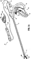
ここで図1Aおよび1Bに言及すれば、双極性鉗子10は、様々な外科的手順をともなう使用のために示される。鉗子10は、一般に、ハウジング20、ハンドルアセンブリ30、回転アセンブリ80、引金アセンブリ70および電極アセンブリ110を備え、これらは相互に協働して管状脈管および脈管組織400をつかみ、シールしそして分割する(図4A参照)。大多数の上記図面は、内視鏡用外科的手順に関連する使用のための双極性鉗子10を描写するが、開放型鉗子200もまた、従来の開放型外科的手順に関連する使用のために企図され、図1B中の実施例によって示され、以下に記載される。本明細書中の目的のために、内視鏡器具または開放型器具のいずれかが、本明細書中に記載される電極アセンブリとともに利用され得る。明らかに、異なる電気的接続および機械的接続ならびに電気的配慮および機械的配慮がそれぞれの特定のタイプの器具に適用されるが、しかしながら、上記電極アセンブリに関する新規な局面およびその動作特性は、一般に、上記開放型設計または内視鏡設計の両方に関して、一貫性を保つ。
(Detailed explanation)
Referring now to FIGS. 1A and 1B,
より特定すれば、鉗子10は、シャフト12を備え、このシャフト12は、上記電極アセンブリ110を係合する大きさにされた遠位端14および上記ハウジング20を機械的に係合する近位端16を有する。このシャフト12は、そのシャフトの上記遠位端14で二叉に分岐し、上記電極アセンブリを受け取り得る。このシャフト12の上記近位端16は上記回転アセンブリ80を機械的に係合し、上記電極アセンブリ110の回転を推進する。上記図面において、および以下の記載においては、用語「近位」とは、従来のように、上記鉗子10のその使用者により近い端をいい、用語「遠位」とは、その使用者からより遠い端をいう。
More particularly,
図1Aで最もよくわかるように、鉗子10はまた、電気的インターフェースまたはプラグ300を備え、その電気的インターフェースまたはプラグ300が、電気外科用エネルギーの源、例えば、電気外科用発電機340に上記鉗子10を接続する(図3B参照)。プラグ300は、一対のピン部材302aおよび302bを備え、これらのピン部材は、上記鉗子10を上記電気外科用発電機340に機械的および電気的に接続するのに必要な大きさにされる。ケーブル310は、上記プラグ300から、上記ケーブル310を上記鉗子10にしっかりと接続する鞘99まで伸長する。ケーブル310は、上記ハウジング20内で内部に分配され、様々な電気的供給経路を通って上記電極アセンブリ110へ電気外科用エネルギーを伝達する。
As best seen in FIG. 1A, the
ハンドルアセンブリ30は、固定ハンドル50および可動式ハンドル40を備える。固定ハンドル50は、ハウジング20に一体として連結され、ハンドル40は、固定ハンドル50に対して可動式であり、以下により詳細に説明されるように、上記電極アセンブリ110の一対の対向する顎部材280および282を駆動する。可動式ハンドル40および引金アセンブリ70は、好ましくは、単体の構造体であり、組立て工程の間に、上記ハウジング20および固定ハンドル50に、適切に作動可能に接続される。
The handle assembly 30 includes a fixed
上記のように、電極アセンブリ110はシャフト12の遠位端14に取り付けられ、一対の対向する顎部材280および282を備える。ハンドルアセンブリ30の可動式ハンドル40は、その顎部材280および282が、互いに関して間隔をあけた関係で配置される開放位置から、その顎部材280および282が、協働してそれらの間に組織400をつかむ締め付け位置または閉じた位置へのその顎部材280および282の動きを賦与する(図4A参照)。
As described above, the
上記鉗子10は、特定の目的に依存してまたは特定の結果を達成するために、それが完全にまたは部分的に使い捨てであるように設計され得ることが想定される。例えば、電極アセンブリ110は、選択的にかつ取り外し可能なように上記シャフト12の上記遠位端14に連結可能であり得、そして/またはシャフト12の上記近位端16は、選択的にかつ取り外し可能なように上記ハウジング20および上記ハンドルアセンブリ30に連結可能であり得る。これら2つの例のいずれかにおいては、上記鉗子10は、「部分的に使い捨て」または「再配置可能」であると考えられ、すなわち、新しい電極アセンブリまたは異なる電極アセンブリ110(または電極アセンブリ110およびシャフト12)が、上記古い電極アセンブリ110を、必要とされる場合に、選択的に置換する。
It is envisioned that the
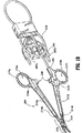
ここで図1Bに言及すれば、開放型鉗子200は、一対の細長いシャフト部分212aを備え、その各々が、それぞれ、近位端216aおよび216bならびに、それぞれ、遠位端214aおよび214bを有する。上記鉗子200は、電極アセンブリ210を備え、この電極アセンブリ210は、シャフト部分212aおよび212bの、それぞれ、遠位端214aおよび214bに付着する。電極アセンブリ210は、対向する顎部材280および282を備え、この顎部材280および282は、軸ピン219の周りで回転可能なように接続される。
Now referring to FIG. 1B, an
好ましくは、各シャフト212aおよび212bは、上記シャフトの上記近位端216aおよび216bに配置されるハンドル217aおよび217bを備え、上記近位端216aおよび216bの各々が、それぞれ、指穴218aおよび218bを規定し、それを通してその使用者の指を受け入れる。理解され得るように、指穴218aおよび218bは、上記シャフト212aおよび212bの互いに対する動きを助長し、上記シャフト212aおよび212bは、その結果として、その顎部材280および282が互いに関して間隔をあけた関係で配置される開放位置から、その顎部材280および282が協働してそれらの間に組織400をつかむ締め付け位置または閉じた位置へ、その顎部材280および282を回転させる。ラチェット230は、好ましくは、回転の間に上記顎部材280および282を様々な位置で互いに対して選択的に固定するために備えられる。
Preferably, each shaft 212a and 212b includes a handle 217a and 21 7 b are disposed in the proximal end 216a and 216b of the shaft, each of the proximal end 216a and 216b, respectively,
好ましくは、上記協働するラチェットインターフェース230に関連する各々の位置は、特定の、すなわち一定の歪みエネルギーを上記シャフト部材212aおよび212b中に保持し、上記シャフト部材212aおよび212bは、その結果として、特定の締め付け力を上記顎部材280および282に伝達する。上記ラチェット230は、目盛または他の可視のマーキングを備え得、その結果、その使用者が、上記顎部材280および282の間の所望の締め付け力の量を容易にそしてすばやく把握し制御することが可能になることは想定される。
Preferably, each position associated with the cooperating
上記シャフトのうちの一つ、例えば、212bは、近位のシャフトコネクタ/フランジ221を備え、それは電気外科用発電機342などの電気外科用エネルギーの源に上記鉗子200を接続するように設計される。さらに特定すれば、フランジ221は、電気外科用ケーブル310を上記鉗子200に機械的に固定し、その結果、その使用者は、必要とされる場合に、選択的に電気外科用エネルギーを印加し得る。上記ケーブル310の上記近位端は、図1Aに関して上記に記載されるものと類似のプラグ300を備える。ケーブル310の内部は、一対のリードを収容し、そのリードは、図2に関して以下に記載されるように、電気外科用発電機340から上記顎部材280および282へ異なる電位を伝導する。
One of the shaft, for example, 212b is provided with a shaft connector /
好ましくは、上記顎部材280および282は、ほぼ対称的であり、類似の構成的特徴を有し、その特徴が、助け合って軸219の周りの容易な回転を可能にし、組織400のつかみおよびシールを成し遂げる。各顎部材280および282は、シールおよび切断の間、協働して上記組織400と係合する。これらの顎部材の一方は、その中に配置される切断要素295を備え、この切断要素295は、以下に詳細に説明される。
Preferably, the
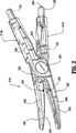
図2に最もよく示されるように、上記電極アセンブリ210の様々な電気的接続は、好ましくは、上記電極アセンブリ210を通しての上記組織接触表面284および286ならびに切断要素295への電気的導通を提供するよう配置される。より特定すれば、二つのコネクタピン307および308が上記電極アセンブリ210の近位端に置かれる。コネクタ307および308は、好ましくは、それぞれ、シャフト212aおよび212bの内部に配置される、対応する電気的接合部(示されていない)に、機械的および電気的に接続される。理解されるように、上記電気的コネクタ307および308は、使い捨ての器具の組立て工程の間に、上記シャフト212aおよび212bに恒久的にはんだ付けされ得るか、あるいは、再配置可能器具にともなう使用のための選択的に脱着可能である。
As best shown in FIG. 2, various electrical connections of the
コネクタ307は、上記電極アセンブリ210内に配置されるリード298へ内部で接続され、顎部材282の組織接触表面286への導通を提供する。同様に、コネクタ308は、リード297へ内部で接続され、顎部材280の組織接触表面284への導通を提供する。コネクタ308はまた、第2の電気的インターフェース309を備え、その電気的インターフェースは、電極アセンブリ210を通して上記切断要素295への導通を提供する。インターフェース308および309は、好ましくは、お互いから誘電体により絶縁されており、上記組織接触表面284または上記切断要素295のいずれかの選択的で独立した活性化を可能にする。あるいは、上記電極アセンブリ210は、1個のコネクタ、例えば、308を備え得、そのコネクタは、上記組織接触表面284または上記切断要素195の選択的で独立した活性化を可能にする内部スイッチを備える。好ましくは、上記リード297、298および299(ならびに/または伝導経路)は、その操作および組織400のつかみの間のお互いに対する上記顎部材280および282の動きを妨げない。同様に、上記顎部材280および282の動きは、必ずしもリード接合部に無理な力をかけない。
図2および図3A〜3Bで最もよく理解されるように、顎部材280および282はともに、それぞれ、伝導性の組織接触表面284および286を備え、これら組織接触表面284および286は、実質的にその長軸方向の長さ全体に沿って配置される(すなわち、実質的に上記それぞれの顎部材280および282の上記近位端から上記遠位端まで伸長する)。組織接触表面284および286は、スタンピングにより、オーバーモールドにより、鋳造により、鋳造品をオーバーモールドすることにより、鋳造品をコーティングすることにより、スタンピングされた電気伝導性シールプレートをオーバーモールドすることによりおよび/または金属射出成形されたシールプレートをオーバーモールドすることにより、上記顎部材280および284に取り付けられ得ることが想定される。これらの製造手法のすべてが、組織に接触しつかむためにその上に配置される電気伝導性の組織接触表面284および286を有する顎部材280および284を製造するために用いられ得る。
As best seen in FIGS. 2 and 3A-3B, both the
好ましくは、上記伝導性のシール面284および286は、ピンチトリム(示されていない)を備え得、そのピンチトリムは、上記電気伝導性の表面284および286のしっかりとした係合を助長し、そしてまた全体の製造プロセスを単純化する。各電気伝導性のシール表面284、286はまた、半径を有する外側周縁端部を備え得、それぞれの顎部材280、282が、一般に上記半径に対し接線方向である隣接する縁端部に沿って、電気伝導性のシール表面284、286に接し、および/または上記半径に沿って電気伝導性のシール表面284、286に接することが想定される。
Preferably, the conductive sealing surfaces 284 and 286 may comprise a pinch trim (not shown) that facilitates secure engagement of the electrically
上記顎部材280および282の上記電気伝導性の組織接触表面284および286は、ともに、それぞれ、実質的にその全体の長軸方向の長さに沿って配置される絶縁体または誘電的な材料290および292を備える。各絶縁体290および292は、それぞれ、その各々の組織接触表面284および286の幅を横切って、実質的に上記組織接触表面284および286の全体の長さに沿ってほぼ中心に置かれ、その結果、これら2つの絶縁体290および292は、一般に、お互いに対向する。
The electrically conductive tissue contacting
好ましくは、絶縁体290、292のうちの一つまたは両方は、セラミック材料の硬度および高温変動に耐える固有の能力に起因して、セラミック材料から作られる。あるいは、この絶縁体290、292のうちの一つまたは両方は、約300〜約600ボルトの範囲の値を有する高比較トラッキング指数(CTI)を有する材料から作られ得る。高CTI材料の例としては、ナイロンおよびDOW Chemicalにより製造されるQUESTRA(登録商標)などのシンジオタクチックポリスチレンが挙げられる。他の材料もまた、単独でか、または組み合わせてのいずれかで利用され得、そのような材料としては、例えば、ナイロン、シンジオタクチックポリスチレン(SPS)、ポリブチレンテレフタレート(PBT)、ポリカーボネート(PC)、アクリロニトリル ブタジエン スチレン(ABS)、ポリフタルアミド(PPA)、ポリイミド、ポリエチレンテレフタレート(PET)、ポリアミド−イミド(PAI)、アクリリック(PMMA)、ポリスチレン(PSおよびHIPS)、ポリエーテルスルホン(PES)、脂肪族ポリケトン、アセタール(POM)コポリマー、ポリウレタン(PUおよびTPU)、ポリフェニレンオキシド分散を伴なうナイロンおよびアクリロニトリル スチレン アクリレートが挙げられる。
Preferably, one or both of the
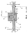
顎部材280は、実質的に絶縁体190内に配置される電気伝導性切断要素295を備える。以下に詳細に記載されるように、切断要素295は、シールプロセスおよび切断プロセスの間に二重の役割を果たす。好ましくは、切断要素295全体が電気伝導性であるが、切断要素295が、伝導性コーティングを上に配置した絶縁材料から作製され得ることが想定される。切断要素295は、絶縁体290および組織接触表面284から距離「B」伸長するように構成され(図3Aを参照のこと)、その結果、切断要素295が、隙間ストップとして働き(すなわち、伝導性シール表面286と286との間に隙間距離「G」を作り出す(図4Aを参照のこと))、これは、正確で一定の効率的な組織シールを促進する。理解され得るように、切断要素295はまた、2つの組織接触表面284および286が触れることを妨げ、一方、シールの間、機器の短絡の可能性を排除する。
上記のように、2つの機械的因子は、シールされる組織の得られる厚みおよび組織シール410の有効性(すなわち、シールプロセスの間の、対向する顎部材280と282との間に適用される圧力、および対向する組織接触表面284と286との間の隙間距離「G」)を決定する際に重要な役割を果たす。好ましくは、切断要素295は、シールの間、一定かつ正確な隙間距離「G」を生じるために、特定の材料特性(例えば、圧縮力、熱膨張など)に従って、組織接触表面284から所定の距離「B」を伸長する(図4A)。好ましくは、シーリングの間の隙間距離「G」は、約0.001インチ〜約0.006インチ、より好ましくは、約0.002インチと約0.003インチとの間の範囲である。対向する組織接触表面284と286との間の締め付け圧力は、好ましくは、約3kg/cm2〜約16kg/cm2の間である。明らかに、切断要素295と対向する絶縁体292との間の圧力は、絶縁体292に対する切断要素295の小さな表面積に起因して、かなり高い。
As described above, two mechanical factors are applied between the resulting thickness of the tissue to be sealed and the effectiveness of the tissue seal 410 (ie, between the opposing
図3Aにおいて最も良く見られ得るように、伝導性切断要素295は、顎部材282の絶縁体292と対向する垂直の位置で向き合う。切断要素295が実質的に鈍く、これは、理解され得るように、最初の電気外科的な活性化の間のシールプロセスを妨げない(すなわち、時期尚早の切断)ことが想定される。言い換えると、外科医は、組織400に機械的に切り込む切断要素295無しで、シール目的のために、組織400を自由に操作し、つかみ、そして締め付ける。さらに、組織切断は、切断要素295と対向する絶縁体292との間の組織を機械的に締め付けることと、電気外科用エネルギーを切断要素295から組織400を通って帰還電極(return electrode))(すなわち、電気伝導性組織接触表面286)へ適用することとの組み合わせによってのみ達成され得る。
As can best be seen in FIG. 3A, the
切断要素295の幾何学的構成が組織切断の全体的な効率を決定する際に重要な役割を果たすことが想定される。例えば、切断要素295の周りの出力/電流濃度は、切断要素295および帰還電極(すなわち、電気伝導性組織接触表面286)への切断要素295の近接の特定の幾何学的構成に基づく。切断要素の特定の幾何学的形状は、高い出力/電流濃度の領域を作り出す。さらに、帰還電極296のこれらの出力/電流濃度が、組織400を通る電場をもたらす。従って、切断要素295および絶縁体292を互いに近接して構成することによって、電流場は、切断のために理想的である高いままであるが、機器は、伝導性表面の間の偶然の接触に起因して短絡しない。理解され得るように、切断要素295の相対的な大きさおよび/または絶縁体292の大きさは、この目的を達成するために選択的に変更され得る。
It is envisioned that the geometry of cutting
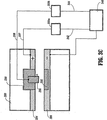
図3Bおよび3Cは、組織接触表面284および286ならびに切断要素295が、どのように、電気外科用発電機340(ESU)およびスイッチコントローラーに電気的に接続され得るかの概略的な例を示す。さらに詳細には、図3Bは、組織接触表面284から伸びる電気リード線297および組織接触表面286から伸びる電気リード線298を示す。さらに詳細には、リード線297は、組織接触表面284をスイッチ350に連結し、リード線352は、スイッチ350をスマートセンサー355に連結し、そしてリード線342は、スマートセンサー355をESU340にそれぞれ連結する。リード線298は、組織接触表面286を直接ESU340に接続する。切断要素295に関して、リード線299は、切断要素295をスイッチ350に連結し、リード線354は、スイッチ350をスマートセンサー355に接続し、そしてリード線342は、スマートセンサー355をESU340にそれぞれ接続する。
3B and 3C show a schematic example of how
理解され得るように、この電気的配置によって、外科医は、2つの対向する組織接触表面284および286が最初に起動して、組織400をシールし得、引き続いて、切断要素295および組織接触表面286を選択的かつ独立して起動して組織400を切断する。従って、組織400は、最初にシールされ、そしてその後、組織を再びつかむことなく、切断する。
As can be appreciated, this electrical arrangement allows the surgeon to first activate two opposing
しかし、切断要素295および組織接触表面286がまた、最初にシールすることなく、組織/脈管を単純に切断するために起動され得ることが想定される。例えば、顎部材280および282が開かれ得、そして切断要素295は、組織400を解剖するかまたは凝固するために選択的に起動され得る。このタイプの代替の実施形態は、特定の内視鏡手順の間に特に有用であり得、ここで、電気外科用ペンシルは、代表的に、操作手順の間に、組織を凝固および/または解剖するために導入される。
However, it is envisioned that cutting
スイッチ350は、外科医が、組織接触表面284または切断要素295を互いに独立に選択的に活性化し得るように使用され得る。理解され得るように、これによって、外科医は、組織400を最初にシールし得、次いで、スイッチ350を単純に切り替えることによって切断要素295を起動し得る。ロッカースイッチ、トグルスイッチ、フリップスイッチ、ダイアルなどが、この目的を達成するために通常使用され得るスイッチの型である。スイッチ350がスマートセンサー355(またはスマート回路、コンピュータ、フィードバックループなど)と協同し得、これが、特定のパラメーターを満たす際、「シーリング」モードと「切断」モードとの間でスイッチ350を切り替えるように自動的に誘発する。例えば、スマートセンサー355は、組織シールが、以下のパラメーター:組織温度、シール410の組織インピーダンス、経時的な組織のインピーダンスの変化および/または経時的な組織に適用される電力または電流の変化のうちの1つ以上に基づいて、完了したときを示すフィードバックループを備え得る。可聴または視覚フィードバックモニター360は、全体的なシールの品質または有効な組織シール410の完了に関する情報を外科医に運ぶために使用され得る。別々のリード線346が、可聴および/または視覚フィードバックの目的で、スマートセンサー355とESUとの間に接続され得る。
The
好ましくは、ESU340は、エネルギーを組織にパルス様の波形で送達する。パルスのエネルギーが、組織に効果的に送達され得るシールエネルギーの量を増加し、そして黒こげ(charring)のような望ましくない組織の影響を減少することが決定された。さらに、スマートセンサー355のフィードバックループは、シールの間、種々の組織パラメーター(すなわち、組織温度、組織インピーダンス、組織を通る電流)を自動的に測定し、黒こげおよび熱の拡散のような種々の組織の影響を減少させるために必要とされるようなエネルギー強度およびパルスの数を自動的に調節するように構成され得る。
Preferably,
RFパルシングが、組織をより効果的に切断するために使用され得ることがまた決定された。例えば、切断要素295から組織400を通る(または組織接触表面284および286から組織400を通る)初期のパルスは、組織シール410に対して最小の影響で、組織400の量または型を効率的かつ一定に切断するための引き続くパルスの理想的な数および引き続くパルスの強度の選択のために、スマートセンサー355にフィードバックを提供するために送達され得る。電気的切断が、一般的に最初の0.01秒〜0.5秒のエネルギー適用内であるスパイクで生じると考えられる。エネルギーがパルスでない場合、組織は、最初に切断されないかもしれないが、切断の最初の段階の間、組織インピーダンスが高いままであるので、乾燥され得る。短く高いエネルギーパルスでエネルギーを提供することによって、組織400がより切断されるようであることが見いだされた。
It has also been determined that RF pulsing can be used to cut tissue more effectively. For example, an initial pulse through the
あるいは、スイッチ350は、所望の切断パラメーターに基づいて、および/または有効なシールが作製されたかもしくは確認された後に活性化するように構成され得る。例えば、組織400を有効にシールした後に、切断要素295は、シール410における所望の末端組織の厚みに基づいて自動的に活性化され得る。
Alternatively, the
図3Cは、伝導性要素(すなわち、組織接触表面284および切断要素295)に別々にかつ独立してエネルギーを与えるために、2つのスイッチ350aおよび350bを利用する本発明の別の代替の実施形態を示す。このように、外科医は、シールをもたらすためのスイッチ350aおよび切断をもたらすためのスイッチ350bを能動的に押し下げる。組織接触表面286は、ESU340に直接連結され、いずれの場合においても帰還電極として作動する。
FIG. 3C illustrates another alternative embodiment of the present invention that utilizes two
ここで、電気外科用機器10(または200)の操作に戻る。図4Aは、シールプロセスの間、対向する伝導性表面284および286から組織400を通る電気外科用エネルギー420の経路を示し、そして図4Bおよび4Cは、切断プロセスの間の切断要素295から組織400を通る電気外科用エネルギー420の経路を示す。より詳細には、図4Aは、組織40が、約3kg/cm2〜約16kg/cm2の範囲の閉鎖圧力「F」で、顎部材280および282の伝導性組織接触表面284と286との間で圧縮されることを示す。正確な力「F」を適用することがまた他の理由のため(脈管の壁に抵抗するため;組織インピーダンスを、組織400を通る十分な電流を可能にする十分に低い値に下げるため;および良好な組織シール410の指標である必要とされる末端組織の厚みを作り出すことに寄与することに加えて、組織加熱の間の膨張力に打ち勝つため)に重要である。約7kg/cm2〜約13kg/cm2の作業範囲内の組織圧力は、動脈および維管束をシールするために特に効果的であることが示されている。
Referring back to the operation of the electrosurgical instrument 10 (or 200). Figure 4A, during the sealing process, shows the path of the
圧縮の際、切断要素295は、ストップ部材として作動し、対向する伝導性組織接触表面284と286と間に隙間「G」を作り出す。好ましくは、隙間距離は、約0.001〜約0.006インチの範囲である。上記のように、伝導性表面284と286との間の隙間距離「G」および締め付け圧力「F」の両方を制御することは、一定かつ有効な組織シールを確実にするために適切に制御される必要がある2つの重要な機械的パラメーターである。外科医は、電気外科用エネルギー420を、組織接触表面284および286へと、組織400を通して送達し、シール410をもたらすために、ESU340およびスイッチ350(上記のように、手動または自動のいずれか)を活性化する。締め付け圧力「F」、隙間距離「G」および電気外科用エネルギー420の独特の組み合わせの結果として、組織コラーゲンは、対向する脈管壁の間で制限された境界を有する融合された塊体に融解する。
Upon compression, cutting
一旦シールされると、外科医は、図4Bおよび4Cに示されるように、切断要素295を活性化する。より詳細には、外科医は、組織400を切断するために、切断要素295にエネルギーを与えるために、スイッチ350を活性化する。上記のように、外科医は、切断するために組織400を再びつかむことは必ずしも必要ではなく、すなわち、切断要素295は、すでに、シールの理想的な中心切断線の近位に位置づけられている。図4Cにおいて最も良く見られ得るように、高度に濃縮された電気外科用エネルギー420(電流場ラインを参照のこと)は、切断要素295の先端から組織400を通って進み、組織400を2つの異なる半体430aおよび430bに切断する。上記のように、組織400を効果的に切断するために必要とされるパルスの数および切断エネルギー420の強度は、厚みおよび/または組織インピーダンスを測定すること、ならびに/あるいは類似のパラメーターを測定する初期較正エネルギーパルスに基づいて、決定され得る。スマートセンサー355(図3Bを参照のこと)またはフィードバックループは、この目的のために使用され得る。
Once sealed, the surgeon activates the cutting
図4Cにおいて最も良く見られるように、切断要素295は、実質的に丸い角を有する対向する角縁部296を備え得る。他の切断要素295の幾何学は、特定の目的に依存して、異なる出力濃度を作り出すために、同様に想像される。
As best seen in FIG. 4C, the cutting
例えば、図5Aは、電極アセンブリ500の1つの代替の例を示し、ここで、顎部材582は、その長手方向長さに沿って延びる絶縁体590を有する組織接触表面584を備える。この実施形態において、絶縁体590は、対向する組織接触表面586に向かって距離「E」を延ばし、シールの間、対向する組織接触表面584と586との間に、ストップ隙間「G」を作り出す。切断要素595は、絶縁体590内で、距離「R」で陥凹しており、その結果、切断要素595は、シールプロセスおよび切断プロセスの間、対向する組織接触表面586に触れない。理解され得るように、組織接触表面586は、切断要素595対向する絶縁体を備えず、従って、全体的な製造プロセスを単純化する。
For example, FIG. 5A shows one alternative example of electrode assembly 500, wherein
この実施形態において、陥凹した切断要素595は、切断要素595の縁部597に対して絶縁体590が近いことに起因して、非常に高い電流密度を作り出すように設計され、すなわち、高い電流密度が、絶縁体/電極インターフェース599において作り出される。理解され得るように、電極アセンブリ510のこの特定の設計は、高圧絶縁体/電極インターフェース599(高圧締め付けゾーン)の隣に、切断要素595を配置する。図5Bにおいて最も良く示されるように、有限要素モデルは、切断要素595を高圧締め付けゾーン598に対して近位に配置する結果として、絶縁体/電極インターフェース599の近いに、高い電流密度の濃度を示す。切断要素595の特定の構成が、より低い出力要件で切断することを可能にすることが想像される。好ましくは、ESU340からのパルス状のRF出力は、上記のように、組織400をより効果的に切断するために使用され得る。
In this embodiment, the recessed
図6Aおよび6bは、本開示の代替の実施形態を示し、ここで、このシール電極の極性は、組織切断をもたらすために、シール後に変更される。より詳細には、図6Aにおいて最も良く示されるように、第1の極性を有するシール電極284aおよび284bの第1の対は、顎部材280に配置され、そして第2の極性を有するシール電極286aおよび286bの第2の対は、顎部材282に配置される。複数の電極濃度293、297、298および299は、それぞれ、電極286b、284b、296aおよび284aを、電気外科用発電機340に接続する。電極284aおよび286aならびに電極284bおよび286bは、互いに対して対向する関係に配置され、その結果、電気外科用エネルギー420は、2つの顎部材280と282との間に保持される場合、組織400を通って効果的に連絡され得る。
FIGS. 6A and 6b show an alternative embodiment of the present disclosure where the polarity of the seal electrode is changed after sealing to effect tissue cutting. More particularly, as best shown in FIG. 6A, a first pair of
初期作動の際、そして顎部材280と282との間に組織400が捕らえられた後に、電気外科用エネルギーが、ほぼ図6Aに示される様式で、組織400を通り、対向する電極284aおよび286aと、電極284bおよび286bとの間で移動される。上記で述べたように、電気外科用エネルギー、対向する電極284aおよび286aと、電極284bおよび286bとの間の制御された隙間距離および制御された閉鎖圧力は、一致し、かつ効率的な組織シールを確実にする。
During initial actuation and after the
一旦、組織が、対向する顎部材の間に効率的にシールされると、外科医は、この組織シールに沿って組織を切断するか、または分割するかを選択し得る。認識され得るように、この器具は、一旦、シールされると組織400を自動的に切断するような形態であり得るか、またはこの器具は、一旦、シールされると外科医が組織400を選択的に分割することを可能にするような形態であり得る。さらに、可聴式または視覚表示器(示さず)がセンサー(示さず)によって誘引され得、有効なシールが生成されたとき、外科医に警告することが想定される。このセンサーは、例えば、組織インピーダンス、組織不透明性および/または組織温度の1つを測定することにより、シールが終了したか否かを決定する。共に所有され、本明細書中に参考として援用される米国出願第10/427,832号は、いくつかの電気的システムを記載し、これは、採用されて、外科医にポジティブフィードバックを提供し、シールの間およびその後に組織パラメーターを決定し、そしてこの組織シールの全体の有効性を決定する。
Once the tissue is effectively sealed between opposing jaw members, the surgeon may choose to cut or divide the tissue along the tissue seal. As can be appreciated, the instrument can be configured to automatically cut
図6Bで最も良く観察されるように、切断ステージの間に、4つの電極の2つ、例えば、電極284bおよび電極286aの電位は充電され、これは、認識され得るように、作動されるとき組織400を通る電気外科用エネルギーの経路を改変する。より詳細には、電気的または電気機械的スイッチ(示さず)が、シールステージの後に活性化され、4つの電極の2つの電位をスイッチし得る。電極284a、284b、286aおよび286bは、特定に目的に依存して切断を行う任意の様式で再構成され得る。
As best observed in FIG. 6B, during the cutting stage, the potential of two of the four electrodes, eg, electrode 284b and
例えば、そして図6Bに示されるように、電極286aおよび284bの電位は、組織400を通る実質的に対角の電気外科的切断経路を奨励するように変更されている。より詳細には、組織インピーダンスが上昇するとき、電気エネルギーが、対向する顎部材上の電気的に対向する電極の方に向かって対角線方向に向く。2つの電気的経路は、ほぼ中心線「C」に沿って組織を横切り、そして切断することが企図される。
For example, and as shown in FIG. 6B, the potentials of
好ましくは、電極284a、284b、286aおよび286bは、選択的または自動的に制御可能であり、組織タイプおよび/または組織厚みにおける固有の変動を考慮して中心線「C」に沿った一致かつ正確な切断を確実にする。さらに、全体の手術プロセスは、組織が初期に捕らえられた後に、外科医が、単に鉗子を活性化し、組織をシールし、次いでこれを切断し得るように自動的に制御され得ることが企図される。この例では、発電機340は、1つ以上のセンサー(示さず)と連絡するための形態とされ、シールおよび切断プロセスの両方に間に、この発電機340へのポジティブフィードバックを提供し、組織400の正確かつ一致したシールおよびその分割を確実にする。上記のように、共に所有される米国特許出願第10/427,832号は、この目的のために採用され得る種々のフィードバック機構を開示する。
Preferably, the
本開示はまた、組織をシールおよび切断するための方法に関し、そして以下の工程:一対の第1および第2の顎部材280、282を有する電極アセンブリ、例えば、210を提供する工程であって、これらが、顎部材280、282が互いに対して間隔をおいた間隔で配置される第1の位置から、顎部材280、282が協働してそれらの間に組織400を捕らえる第2の位置に、互いに対して移動可能である工程を含む。好ましくは、顎部材280、282の各々は、それぞれ、ESU340に連結される電気的に導電性の組織接触表面284、286を含む。
The present disclosure also relates to a method for sealing and cutting tissue and providing the following steps: an electrode assembly having a pair of first and
電気的に導電性の切断要素295は、第1の組織接触表面284内に誘電的に配置され、そしてこの切断要素295は、第1の組織接触表面284から第2の組織接触表面286に向かって延びる。好ましくは、組織接触表面284、286が組織400の周りで閉鎖されるとき、この切断要素295は、第1および第2の組織接触表面284、286間に約0.001インチと約0.006インチの間の隙間「G」を生成する。絶縁体が、第2の組織接触表面286内に上記切断要素の実質的に対向する関係で配置される。
An electrically
上記方法は、さらに、以下の工程:顎部材280、282を作動し、組織接触表面284、286間に組織400を捕らえる工程;組織接触表面284、286に約3kg/cm2と約16kg/cm2との間の閉鎖力「F」を、上記切断要素295が第1および第2の組織接触表面284、286間に隙間「G」を生成するように付与する工程;組織接触表面284、286にエネルギーを与え、組織400を通って電気外科用エネルギー420を送達し、組織シール410を行う工程;および上記切断要素295と第2の組織接触表面286にエネルギーを与え、組織400を通じて電気外科用エネルギー420を送達し、上記組織シール410に沿って組織400を効率的に切断する工程を含む。
The method further includes the following steps: actuating
上記第1および第2の組織接触表面284、286にエネルギーを与え、シール410を行う工程の後に、上記方法は:組織400を切断する工程の前に、スマートセンサーを利用してシールの質を決定する工程を含み得る。
After energizing the first and second
前述および種々の図面の描写から、当業者は、特定の改変もまた、現在の開示の範囲から逸脱することなく現在の開示になされ得ることを認識する。例えば、鉗子10または200に他の特徴、例えば、細長いシャフト12、212に対して電極アセンブリ110、210を軸方向に配置する関節アセンブリを付加することが好適であり得る。上記組織接触表面284および286は、半径をもつエッジを含み得、シールを容易にし、そしてシールの間に組織への可能な付随的な損傷を減少する。
From the foregoing and various drawings, those skilled in the art will recognize that certain modifications can also be made to the current disclosure without departing from the scope of the current disclosure. For example, it may be preferable to add other features to the
鉗子10(および/またはこの鉗子10と組み合わされて用いられるESU340)は、第2のスマートセンサー、または適切な量の電気外科用エネルギーを自動的に選択し、顎部材280と282との間に捕われた特定サイズの組織を有効にシールするさらなるフィードバック機構(示さず)を含み得る。
Forceps 10 (and / or ESU340 used in combination with the forceps 10), the second smart sensor or automatically selects the appropriate amount of electrosurgical energy, between the
顎部材280および282の外側表面は、活性化、シールおよび切断の間に、顎部材280、282(またはそのコンポーネント)と周辺組織との間の接着を減少するために設計される、ニッケルを基礎にした材料、被覆、スタンピングおよび/または金属射出成形を含み得る。さらに、組織接触表面284および286は、以下の材料の1つ(または1つ以上の組み合わせ)から製造され得る:ニッケル−クロム、窒化クロム、OHIOのThe Electrolizing Corporationによって製造されるMedCoat 2000、inconel 600および錫−ニッケル。組織接触表面284、286および/または導電性切断要素295はまた、上記材料の1つ以上で被覆され得、同じ結果、すなわち、「非粘着性表面」を達成する。
The outer surfaces of the
好ましくは、これら非粘着性材料は、機械的な歯の接着を防ぐ平滑表面を提供するクラスの材料である。シール表面284および286および/または導電性切断要素295上で利用されるとき、これら材料は、表面テクスチャー、および電気的影響および生物学的組織存在における腐食に起因する表面分解を受けることに部分的に起因する粘着をなくすために最適表面エネルギーを提供する。これら材料は、ステンレス鋼と比べ優れた非粘着性質を示することが想定され、そして、圧力および電気外科用エネルギーに曝すことが組織接着をより受け易い局在化された「ホットスポット」を生成し得る領域中の鉗子10、200上で利用される。認識され得るように、シールの間に組織「粘着」の量を減少することは、器具の全体の効力を改善する。
Preferably, these non-tacky materials are a class of materials that provide a smooth surface that prevents mechanical tooth adhesion. When utilized on sealing
上記で述べたように、上記非粘着材料は、以下の「非粘着」材料の1つ(または1つ以上の組み合わせ)から製造され得る:ニッケル−クロム、窒化クロム、MedCoat 2000、Inconel 600および錫−ニッケル。例えば、高ニッケルクロム合金、Ni200、Ni201(約100%のNi)は、シール表面284、286または切断要素295に、金属射出成形、スタンピング、機械加工または任意の同様のプロセスによりその作製に用いられ得る。また、そして上記のように、組織表面284および286、および/または導電性切断要素295はまた、上記材料の1つ以上で被覆され得、同じ結果、すなわち、「非粘着表面」を達成する。例えば、窒化物被覆(またはその他の上記で同定された材料の1つ以上)が、蒸着製造技法を用いて別の基礎材料(金属または非金属)上の被覆として堆積され得る。
As noted above, the non-stick material may be made from one (or a combination of one or more) of the following “non-stick” materials: nickel-chromium, chromium nitride, MedCoat 2000, Inconel 600 and tin. Nickel. For example, a high nickel chromium alloy, Ni200, Ni201 (about 100% Ni) is used to make
本明細書で開示される材料の1つの特定のクラスは、優れた非粘着性質を、そして、いくつかの例では、優れたシールの質を示した。例えば、制限されずに:TiN、ZrN、TiAlN、およびCrNを含む窒化物被覆は、非粘着目的のために用いられる好適な材料である。CrNは、その全体の表面性質および最適性能に起因して非粘着目的に特に有用であることが見出された。その他のクラスの材料もまた、全体の粘着を低減することが見出された。例えば、約5:1のNi/Cr比の高ニッケル/クロム合金が、双極器具で粘着を有意に減少することが見出された。このクラスの1つの特に有用な非粘着材料は、Inconel 600である。Ni200、Ni201(約100%のNi)から作製されるか、または被覆されたシール表面284および286を有する双極器具もまた、代表的な双極ステンレス鋼電極に対して改良された非粘着性能を示した。
One particular class of materials disclosed herein has demonstrated excellent non-stick properties and, in some instances, excellent seal quality. For example, without limitation: TiN, ZrN, nitride coating comprising Ti Al N, and CrN are preferred materials used for non-stick purposes. CrN has been found to be particularly useful for non-stick purposes due to its overall surface properties and optimal performance. Other classes of materials have also been found to reduce overall sticking. For example, from about 5: 1 of high nickel / chromium alloy of Ni / Cr ratio was found to significantly reduce the adhesive in a bipolar instrument. One particularly useful non-stick material of this class is Inconel 600. Ni200, Ni201 (about 100% Ni) or is made from or coated bipolar instrument having a sealing
例として、窒化クロムは、薄い均一な被覆を全体の導電性表面に付与する物理的蒸着(PVD)プロセスを用いて付与され得る。この被覆は、いくつかの効果:1)この被覆は、組織の表面への機械的接着に寄与する金属表面上の微細構造を充填する;2)この被覆は、非常に硬く、かつ酸化および腐食を最小にする非反応性材料である;および3)この被覆は、乾燥およびシールの質をさらに高める導電性表面加熱を引き起こすベース金属より抵抗性である傾向にある;を生成する。 As an example, chromium nitride can be applied using a physical vapor deposition (PVD) process that provides a thin, uniform coating to the entire conductive surface. This coating has several effects: 1) The coating fills the microstructure on the metal surface that contributes to mechanical adhesion to the surface of the tissue; 2) The coating is very hard and oxidizes and corrodes some with a non-reactive material which minimizes; and 3) the coating tends Ru near a dry and seal quality a further increase conductive surface heating resistance than spawning be based metal; generating a.
このInconel 600被覆は、Conroe Texasに位置するSpecial Metals、Inc.によって製造される、いわゆる「スーパーアロイ」である。この合金は、主に、腐食および熱に対する耐性が必要である環境で用いられている。Inconelの高ニッケル含量は、この材料を、有機的な腐食に対して特に耐性にする。認識され得るように、これらの性質は、高温、高RFエネルギーおよび有機物質に自然に曝される双極電気外科用器具のために所望される。さらに、Inconelの抵抗性は、代表的には、基礎導電性材料より高く、これは、乾燥およびシールの質をさらに増加する。 This Inconel 600 coating is available from Special Metals, Inc., located in Conroe Texas. Is a so-called “superalloy” manufactured by This alloy is mainly used in environments where resistance to corrosion and heat is required. The high nickel content of Inconel makes this material particularly resistant to organic corrosion. As can be appreciated, these properties are desirable for bipolar electrosurgical instruments that are naturally exposed to high temperatures, high RF energy and organic materials. Furthermore, the resistance of Inconel is typically higher than the base conductive material, which further increases the quality of drying and sealing.
本明細書で開示されるように、本発明は、異なる電位を有し、対向する電気的に導電性のシール表面を通じて電気外科用エネルギーを移動し、血管をシールすることに関する。しかし、本明細書で論議される現在開示される実施形態は、いわゆる「抵抗加熱」を用いて組織構造をシールするために設計され得、そのために、組織接触表面284および286は、必ずしも電気的に導電性である必要はないことが企図される。むしろ、組織接触表面284および286の各々は、従来の「ホットプレート」と同様に加熱され、これら表面284および286は、接触に際し(または活性化に際し各々の表面284および286を選択的に加熱するスイッチ(示さず)の活性化に際し)協働して組織をシールする。
As disclosed herein, the present invention relates to transferring electrosurgical energy and sealing blood vessels through opposing electrically conductive sealing surfaces having different potentials. However, the presently disclosed embodiments discussed herein may be designed to seal tissue structures using so-called “resistance heating”, so that the
好ましくは、現在開示される鉗子10、200は、外科医が組織に移動される電気外科用エネルギーを選択的に制御してシールおよび/または切断のいずれかを行うことを可能にするフットスイッチ(示さず)に電気的にカップルするように設計される。ハンドスイッチ(示さず)もまた、利用され得る。認識され得るように、鉗子10、200上にハンドスイッチを位置決めすることは、多くの利点を有する。例えば、このハンドスイッチは、手術室中の電気ケーブルの量を減らし、そして、実質的に、「視野方向」活性化に起因する外科的手順の間の間違った器具または機能を活性化する可能性をなくす。
Preferably, the presently disclosed
切断要素295は、シール後、組織400を分割するために外科医によって選択的に活性化が可能である切断ワイヤのような寸法であり得る。より詳細には、ワイヤは、顎部材280と282との間の絶縁体290内にマウントされ、そしてスイッチ350の活性化に際し選択的にエネルギーを与えられる。
Cutting
電極アセンブリ110、210は、特定の目的に依存して、シャフト12、212から、それぞれ選択的に離脱可能(すなわち、再配置可能)であり得ることが想定される。あるいは、全体の器具は使い捨てであり得る。例えば、特有の鉗子10、200は、異なる組織タイプまたは厚みのための形態であり得ることが企図される。さらに、再利用可能な鉗子10、200が、異なる組織タイプのための異なる電極アセンブリ110、210を有するキットとして販売され得ることが想定される。外科医は、単に、特定の組織タイプのための適切な電極アセンブリを選択する。
It is envisioned that the
可変レジスターが、特定の組織タイプをシールするか、そして/または切断するために電気外科用エネルギーを調節するために採用され得ることもまた想定される。この可変レジスターは、組織タイプ、組織インピーダンス、組織水分、組織厚みなどを決定するセンサーにカップルされ得、そして、組織をシールおよび/または切断するためにこの可変レジスターを自動的に調節することによって適切な電気外科用エネルギーを調節する。 It is also envisioned that a variable resistor can be employed to adjust the electrosurgical energy to seal and / or cut a particular tissue type. This variable resistor can be coupled to a sensor that determines tissue type, tissue impedance, tissue moisture, tissue thickness, etc. and is suitable by automatically adjusting this variable resistor to seal and / or cut tissue Adjust the electrosurgical energy.
図1〜4Cは、切断要素295が、絶縁体290から第2の組織接触表面286に向かって延びるように示すが、同じかまたは類似の目的を達成し得るその他の顎配列が可能であることが想定される。例えば、切断要素295は、絶縁体290内で相対的に同一平面であり得、そして底部絶縁表面292は、この組織接触表面286を超え、対向する第1の組織接触表面284に向かって延び得る。さらに、この切断要素および絶縁表面292の両方は同一平面上にあり、そして隙間ストップが、組織接触表面のいずれか、または器具のいずれかに生成される。停止部材形態および停止隙間アクチュエーターの種々の実施形態は、共に所有されるPCT特許出願番号第PCT US02/01890号および同第PCT/US01/11413号、ならびに共に所有され、かつ同時に出願されたK.Johnson、S.DycusおよびG.Coutureによる「血管をシールするための電気外科用器具」と題する米国特許出願[代理人番号第11584/203−3311号]に開示され、これらの内容はすべてそれらの全体が本明細書中に本明細書によって援用される。
1-4C show the cutting
主題の鉗子および電極アセンブリが好適な実施形態に関して記載されているが、変更および改変が主題のデバイスの思想または範囲から逸脱することなくそれらにさなれ得ることは、それが所属する当業者に容易に明らかである。 Although the subject forceps and electrode assembly have been described with respect to preferred embodiments, it is readily apparent to those skilled in the art to which they belong that changes and modifications can be made without departing from the spirit or scope of the subject device. Is obvious.
本開示のいくつかの実施形態は図面に示されているが、本開示はそれに制限されることは意図されず、本開示は技術が可能であり、しかも明細書が同様に読まれる範囲と同じ程度広い。従って、上記の説明は、制限的であるとして解釈されるべきではなく、好ましい実施形態の単なる例示である。当業者は、本明細書に添付した請求項の範囲および思想内のその他の改変を想定する。 Although some embodiments of the present disclosure are shown in the drawings, the present disclosure is not intended to be limited thereto, and the present disclosure is capable of technology and is the same as the scope in which the specification is similarly read. About wide. Therefore, the above description should not be construed as limiting, but merely as exemplifications of preferred embodiments. Those skilled in the art will envision other modifications within the scope and spirit of the claims appended hereto.
本主題の器具の様々な実施形態が、本明細書中で以下の図面に関して記載される。 Various embodiments of the subject device are described herein with reference to the following drawings.
Claims (14)
一対の対向する第一および第二の顎部材であって、該顎部材が互いに対して間隔を置いた関係で配置される第一の位置から、該顎部材がその間に組織を保持するように共同して働く第二の位置へ、互いに対して移動可能である、顎部材を備え、
各顎部材が電気伝導性の組織接触表面を含み、各組織接触表面が電気外科用エネルギー源に接続され、その結果、組織接触表面がその間に保持される組織を介して電気外科用エネルギーを伝導し得、シールを実施し、
該第一の顎部材が、該第一の組織接触表面内に誘電的に配置される電気伝導性の切断要素を含み、かつ該第二の顎部材が、そこに配置される絶縁体を含み、該絶縁体は実質的に該切断要素と対向する関係で配置され、
シールの間に該組織表面の間に隙間を生成するために、該切断要素が、該第一の組織接触表面から該第二の組織接触表面に向かって延び、かつ該切断要素および該第一の組織接触表面が、外科医により独立して作動可能であり、
該切断要素が実質的に鈍く、かつ電気外科用エネルギー供給を介してのみ組織を切断可能である、
アセンブリ。An electrode assembly for use with an instrument for sealing a blood vessel, the electrode assembly comprising:
A pair of opposing first and second jaw members such that the jaw members retain tissue therebetween from a first position in which the jaw members are disposed in spaced relation to each other; Comprising jaw members that are movable relative to each other to a second position that works together;
Each jaw member includes an electrically conductive tissue contacting surface, and each tissue contacting surface is connected to an electrosurgical energy source so that the tissue contacting surface conducts electrosurgical energy through the tissue held therebetween. Can be sealed,
The first jaw member includes an electrically conductive cutting element that is dielectrically disposed within the first tissue contacting surface, and the second jaw member includes an insulator disposed therein. The insulator is disposed in a substantially opposing relationship with the cutting element;
The cutting element extends from the first tissue contacting surface toward the second tissue contacting surface to create a gap between the tissue surfaces during sealing, and the cutting element and the first tissue contacting surface of, Ri operably der independently by a surgeon,
The cutting element is substantially blunt and can only cut tissue via an electrosurgical energy supply;
assembly.
電極アセンブリであって、該アセンブリは、以下:
一対の対向する第一および第二の顎部材であって、該顎部材が互いに対して間隔をおいて配置された第一の位置から、該顎部材がその間に組織を保持するように共同して働く第二の位置へ、互いに対して移動可能であり、
各顎部材が電気伝導性の組織接触表面を含み、各組織接触表面が電気外科用エネルギー源に接続される、顎部材;
該第一の組織接触表面内に誘電的に配置された電気伝導性切断要素であって、該切断要素が、該第一の組織接触表面から該第二の組織接触表面に向かって延びる切断要素、
該第二の組織接触表面内に配置された絶縁体であって、該絶縁体が、実質的に該切断要素に対向する関係で配置される絶縁体、
を備える、電極アセンブリ;
該顎部材を組織接触表面の間に組織を保持するように作動させるための手段;
組織接触表面の間に約3kg/cm2〜16kg/cm2の間の閉鎖力を適用し、その結果、該切断要素が該第一の組織接触表面と該第二の組織接触表面との間の隙間を生成するための手段;
該第一の組織接触表面および該第二の組織接触表面にエネルギーを与え、該組織を介して電気外科用エネルギーを伝達し、組織のシールを実施するための手段;ならびに
該切断要素および該第二の組織接触表面にエネルギーを与え、該組織を介してエネルギーを伝達し、組織シールに沿って組織を効果的に切断するための手段
を備える、システム。A system for sealing and cutting tissue, the system comprising:
An electrode assembly comprising:
A pair of opposing first and second jaw members, wherein the jaw members cooperate to hold tissue therebetween from a first position spaced apart from each other; Are movable relative to each other to a second position that works
Jaw members, each jaw member including an electrically conductive tissue contacting surface, each tissue contacting surface being connected to an electrosurgical energy source;
An electrically conductive cutting element dielectrically disposed within the first tissue contacting surface, the cutting element extending from the first tissue contacting surface toward the second tissue contacting surface ,
An insulator disposed within the second tissue contacting surface, wherein the insulator is disposed in a substantially opposite relationship to the cutting element;
An electrode assembly;
Means for actuating the jaw members to hold tissue between tissue contacting surfaces;
Applying a closure force of between about 3kg / cm 2 ~16kg / cm 2 between the tissue contacting surfaces, between a result, the cutting element is said first tissue contacting surface and said second tissue contacting surface Means for generating a gap of
Means for energizing the first tissue contacting surface and the second tissue contacting surface, transmitting electrosurgical energy through the tissue and performing a tissue seal; and the cutting element and the second A system comprising means for energizing a second tissue contacting surface, transferring energy through the tissue, and effectively cutting the tissue along a tissue seal.
Applications Claiming Priority (2)
| Application Number | Priority Date | Filing Date | Title |
|---|---|---|---|
| US41606402P | 2002-10-04 | 2002-10-04 | |
| PCT/US2003/028539 WO2004032777A1 (en) | 2002-10-04 | 2003-09-11 | Electrode assembly for sealing and cutting tissue and method for performing same |
Related Child Applications (1)
| Application Number | Title | Priority Date | Filing Date |
|---|---|---|---|
| JP2009186889A Division JP4944171B2 (en) | 2002-10-04 | 2009-08-11 | Electrode assembly for sealing and cutting tissue and method for performing sealing and cutting tissue |
Publications (3)
| Publication Number | Publication Date |
|---|---|
| JP2006501939A JP2006501939A (en) | 2006-01-19 |
| JP2006501939A5 JP2006501939A5 (en) | 2006-08-24 |
| JP4459814B2 true JP4459814B2 (en) | 2010-04-28 |
Family
ID=32093809
Family Applications (3)
| Application Number | Title | Priority Date | Filing Date |
|---|---|---|---|
| JP2004543287A Expired - Fee Related JP4459814B2 (en) | 2002-10-04 | 2003-09-11 | Electrode assembly for sealing and cutting tissue and method for performing sealing and cutting tissue |
| JP2009186889A Expired - Fee Related JP4944171B2 (en) | 2002-10-04 | 2009-08-11 | Electrode assembly for sealing and cutting tissue and method for performing sealing and cutting tissue |
| JP2011233415A Pending JP2012045405A (en) | 2002-10-04 | 2011-10-24 | Electrode assembly for sealing and cutting tissue and method for sealing and cutting tissue |
Family Applications After (2)
| Application Number | Title | Priority Date | Filing Date |
|---|---|---|---|
| JP2009186889A Expired - Fee Related JP4944171B2 (en) | 2002-10-04 | 2009-08-11 | Electrode assembly for sealing and cutting tissue and method for performing sealing and cutting tissue |
| JP2011233415A Pending JP2012045405A (en) | 2002-10-04 | 2011-10-24 | Electrode assembly for sealing and cutting tissue and method for sealing and cutting tissue |
Country Status (7)
| Country | Link |
|---|---|
| EP (2) | EP1795140B1 (en) |
| JP (3) | JP4459814B2 (en) |
| AU (2) | AU2003270566B2 (en) |
| CA (1) | CA2500593C (en) |
| DE (1) | DE60312348T2 (en) |
| ES (1) | ES2283808T3 (en) |
| WO (1) | WO2004032777A1 (en) |
Families Citing this family (255)
| Publication number | Priority date | Publication date | Assignee | Title |
|---|---|---|---|---|
| US7364577B2 (en) | 2002-02-11 | 2008-04-29 | Sherwood Services Ag | Vessel sealing system |
| US7118570B2 (en) | 2001-04-06 | 2006-10-10 | Sherwood Services Ag | Vessel sealing forceps with disposable electrodes |
| US7887535B2 (en) | 1999-10-18 | 2011-02-15 | Covidien Ag | Vessel sealing wave jaw |
| US7101371B2 (en) | 2001-04-06 | 2006-09-05 | Dycus Sean T | Vessel sealer and divider |
| AU2001249933B2 (en) | 2001-04-06 | 2006-06-08 | Covidien Ag | Vessel sealer and divider with non-conductive stop members |
| US10849681B2 (en) | 2001-04-06 | 2020-12-01 | Covidien Ag | Vessel sealer and divider |
| US7270664B2 (en) * | 2002-10-04 | 2007-09-18 | Sherwood Services Ag | Vessel sealing instrument with electrical cutting mechanism |
| US7931649B2 (en) * | 2002-10-04 | 2011-04-26 | Tyco Healthcare Group Lp | Vessel sealing instrument with electrical cutting mechanism |
| US7276068B2 (en) * | 2002-10-04 | 2007-10-02 | Sherwood Services Ag | Vessel sealing instrument with electrical cutting mechanism |
| US7799026B2 (en) | 2002-11-14 | 2010-09-21 | Covidien Ag | Compressible jaw configuration with bipolar RF output electrodes for soft tissue fusion |
| US7776036B2 (en) | 2003-03-13 | 2010-08-17 | Covidien Ag | Bipolar concentric electrode assembly for soft tissue fusion |
| AU2004237772B2 (en) | 2003-05-01 | 2009-12-10 | Covidien Ag | Electrosurgical instrument which reduces thermal damage to adjacent tissue |
| US8128624B2 (en) | 2003-05-01 | 2012-03-06 | Covidien Ag | Electrosurgical instrument that directs energy delivery and protects adjacent tissue |
| US7160299B2 (en) | 2003-05-01 | 2007-01-09 | Sherwood Services Ag | Method of fusing biomaterials with radiofrequency energy |
| ES2368488T3 (en) | 2003-05-15 | 2011-11-17 | Covidien Ag | FABRIC SEALER WITH VARIABLE BUMPER MEMBERS SELECTIVELY AND NON-DRIVING. |
| US7156846B2 (en) | 2003-06-13 | 2007-01-02 | Sherwood Services Ag | Vessel sealer and divider for use with small trocars and cannulas |
| USD956973S1 (en) | 2003-06-13 | 2022-07-05 | Covidien Ag | Movable handle for endoscopic vessel sealer and divider |
| US7150749B2 (en) | 2003-06-13 | 2006-12-19 | Sherwood Services Ag | Vessel sealer and divider having elongated knife stroke and safety cutting mechanism |
| US9848938B2 (en) | 2003-11-13 | 2017-12-26 | Covidien Ag | Compressible jaw configuration with bipolar RF output electrodes for soft tissue fusion |
| US7367976B2 (en) | 2003-11-17 | 2008-05-06 | Sherwood Services Ag | Bipolar forceps having monopolar extension |
| US7131970B2 (en) | 2003-11-19 | 2006-11-07 | Sherwood Services Ag | Open vessel sealing instrument with cutting mechanism |
| US7811283B2 (en) | 2003-11-19 | 2010-10-12 | Covidien Ag | Open vessel sealing instrument with hourglass cutting mechanism and over-ratchet safety |
| US7442193B2 (en) | 2003-11-20 | 2008-10-28 | Covidien Ag | Electrically conductive/insulative over-shoe for tissue fusion |
| DE102004026179B4 (en) * | 2004-05-14 | 2009-01-22 | Erbe Elektromedizin Gmbh | Electrosurgical instrument |
| DE102004031141A1 (en) * | 2004-06-28 | 2006-01-26 | Erbe Elektromedizin Gmbh | Electrosurgical instrument |
| DE102004055671B4 (en) | 2004-08-11 | 2010-01-07 | Erbe Elektromedizin Gmbh | Electrosurgical instrument |
| US7686827B2 (en) | 2004-10-21 | 2010-03-30 | Covidien Ag | Magnetic closure mechanism for hemostat |
| US7686804B2 (en) | 2005-01-14 | 2010-03-30 | Covidien Ag | Vessel sealer and divider with rotating sealer and cutter |
| US7909823B2 (en) | 2005-01-14 | 2011-03-22 | Covidien Ag | Open vessel sealing instrument |
| US7837685B2 (en) | 2005-07-13 | 2010-11-23 | Covidien Ag | Switch mechanisms for safe activation of energy on an electrosurgical instrument |
| US7628791B2 (en) | 2005-08-19 | 2009-12-08 | Covidien Ag | Single action tissue sealer |
| US7879035B2 (en) | 2005-09-30 | 2011-02-01 | Covidien Ag | Insulating boot for electrosurgical forceps |
| ES2381560T3 (en) | 2005-09-30 | 2012-05-29 | Covidien Ag | Insulating sleeve for electrosurgical forceps |
| CA2561034C (en) | 2005-09-30 | 2014-12-09 | Sherwood Services Ag | Flexible endoscopic catheter with an end effector for coagulating and transfecting tissue |
| US7922953B2 (en) | 2005-09-30 | 2011-04-12 | Covidien Ag | Method for manufacturing an end effector assembly |
| US7722607B2 (en) | 2005-09-30 | 2010-05-25 | Covidien Ag | In-line vessel sealer and divider |
| US7789878B2 (en) | 2005-09-30 | 2010-09-07 | Covidien Ag | In-line vessel sealer and divider |
| US8882766B2 (en) * | 2006-01-24 | 2014-11-11 | Covidien Ag | Method and system for controlling delivery of energy to divide tissue |
| US8734443B2 (en) | 2006-01-24 | 2014-05-27 | Covidien Lp | Vessel sealer and divider for large tissue structures |
| US8298232B2 (en) | 2006-01-24 | 2012-10-30 | Tyco Healthcare Group Lp | Endoscopic vessel sealer and divider for large tissue structures |
| US7846158B2 (en) | 2006-05-05 | 2010-12-07 | Covidien Ag | Apparatus and method for electrode thermosurgery |
| US20070265616A1 (en) * | 2006-05-10 | 2007-11-15 | Sherwood Services Ag | Vessel sealing instrument with optimized power density |
| US7776037B2 (en) | 2006-07-07 | 2010-08-17 | Covidien Ag | System and method for controlling electrode gap during tissue sealing |
| US7717914B2 (en) * | 2006-07-11 | 2010-05-18 | Olympus Medical Systems Corporation | Treatment device |
| US7744615B2 (en) | 2006-07-18 | 2010-06-29 | Covidien Ag | Apparatus and method for transecting tissue on a bipolar vessel sealing instrument |
| US8597297B2 (en) * | 2006-08-29 | 2013-12-03 | Covidien Ag | Vessel sealing instrument with multiple electrode configurations |
| AU2008221509B2 (en) | 2007-09-28 | 2013-10-10 | Covidien Lp | Dual durometer insulating boot for electrosurgical forceps |
| US9023043B2 (en) | 2007-09-28 | 2015-05-05 | Covidien Lp | Insulating mechanically-interfaced boot and jaws for electrosurgical forceps |
| GB0804688D0 (en) * | 2008-03-13 | 2008-04-16 | Gyrus Group Plc | Surgical instrument |
| CA3161692A1 (en) | 2008-03-31 | 2009-10-08 | Applied Medical Resources Corporation | Electrosurgical system |
| JP5079085B2 (en) * | 2008-04-21 | 2012-11-21 | オリンパスメディカルシステムズ株式会社 | THERAPEUTIC TREATMENT SYSTEM AND THERAPEUTIC TREATMENT TOOL |
| US8357158B2 (en) | 2008-04-22 | 2013-01-22 | Covidien Lp | Jaw closure detection system |
| US8469956B2 (en) | 2008-07-21 | 2013-06-25 | Covidien Lp | Variable resistor jaw |
| GB2462453B (en) * | 2008-08-06 | 2012-05-09 | Gyrus Medical Ltd | Electrosurgical instrument and system |
| US9603652B2 (en) | 2008-08-21 | 2017-03-28 | Covidien Lp | Electrosurgical instrument including a sensor |
| US9375254B2 (en) | 2008-09-25 | 2016-06-28 | Covidien Lp | Seal and separate algorithm |
| US8968314B2 (en) | 2008-09-25 | 2015-03-03 | Covidien Lp | Apparatus, system and method for performing an electrosurgical procedure |
| US8142473B2 (en) | 2008-10-03 | 2012-03-27 | Tyco Healthcare Group Lp | Method of transferring rotational motion in an articulating surgical instrument |
| US8016827B2 (en) | 2008-10-09 | 2011-09-13 | Tyco Healthcare Group Lp | Apparatus, system, and method for performing an electrosurgical procedure |
| US8197479B2 (en) | 2008-12-10 | 2012-06-12 | Tyco Healthcare Group Lp | Vessel sealer and divider |
| US8114122B2 (en) | 2009-01-13 | 2012-02-14 | Tyco Healthcare Group Lp | Apparatus, system, and method for performing an electrosurgical procedure |
| US8187273B2 (en) | 2009-05-07 | 2012-05-29 | Tyco Healthcare Group Lp | Apparatus, system, and method for performing an electrosurgical procedure |
| US8246618B2 (en) | 2009-07-08 | 2012-08-21 | Tyco Healthcare Group Lp | Electrosurgical jaws with offset knife |
| US8430876B2 (en) | 2009-08-27 | 2013-04-30 | Tyco Healthcare Group Lp | Vessel sealer and divider with knife lockout |
| US8357159B2 (en) | 2009-09-03 | 2013-01-22 | Covidien Lp | Open vessel sealing instrument with pivot assembly |
| US8133254B2 (en) | 2009-09-18 | 2012-03-13 | Tyco Healthcare Group Lp | In vivo attachable and detachable end effector assembly and laparoscopic surgical instrument and methods therefor |
| US8112871B2 (en) | 2009-09-28 | 2012-02-14 | Tyco Healthcare Group Lp | Method for manufacturing electrosurgical seal plates |
| US9024237B2 (en) | 2009-09-29 | 2015-05-05 | Covidien Lp | Material fusing apparatus, system and method of use |
| US8512371B2 (en) | 2009-10-06 | 2013-08-20 | Covidien Lp | Jaw, blade and gap manufacturing for surgical instruments with small jaws |
| US8480671B2 (en) | 2010-01-22 | 2013-07-09 | Covidien Lp | Compact jaw including split pivot pin |
| US8556929B2 (en) | 2010-01-29 | 2013-10-15 | Covidien Lp | Surgical forceps capable of adjusting seal plate width based on vessel size |
| US8597295B2 (en) | 2010-04-12 | 2013-12-03 | Covidien Lp | Surgical instrument with non-contact electrical coupling |
| US8439913B2 (en) | 2010-04-29 | 2013-05-14 | Covidien Lp | Pressure sensing sealing plate |
| US8469991B2 (en) | 2010-06-02 | 2013-06-25 | Covidien Lp | Apparatus for performing an electrosurgical procedure |
| US8430877B2 (en) | 2010-06-02 | 2013-04-30 | Covidien Lp | Apparatus for performing an electrosurgical procedure |
| US8491624B2 (en) | 2010-06-02 | 2013-07-23 | Covidien Lp | Apparatus for performing an electrosurgical procedure |
| US8512336B2 (en) * | 2010-07-08 | 2013-08-20 | Covidien Lp | Optimal geometries for creating current densities in a bipolar electrode configuration |
| DE102010036534B4 (en) | 2010-07-21 | 2019-01-31 | Erbe Elektromedizin Gmbh | Electrosurgical device |
| US8641712B2 (en) | 2010-07-28 | 2014-02-04 | Covidien Lp | Local optimization of electrode current densities |
| US8298233B2 (en) | 2010-08-20 | 2012-10-30 | Tyco Healthcare Group Lp | Surgical instrument configured for use with interchangeable hand grips |
| US8814864B2 (en) | 2010-08-23 | 2014-08-26 | Covidien Lp | Method of manufacturing tissue sealing electrodes |
| US8899461B2 (en) * | 2010-10-01 | 2014-12-02 | Covidien Lp | Tissue stop for surgical instrument |
| EP2621389B1 (en) * | 2010-10-01 | 2015-03-18 | Applied Medical Resources Corporation | Electrosurgical instrument with jaws and with an electrode |
| US9655672B2 (en) * | 2010-10-04 | 2017-05-23 | Covidien Lp | Vessel sealing instrument |
| US9113940B2 (en) | 2011-01-14 | 2015-08-25 | Covidien Lp | Trigger lockout and kickback mechanism for surgical instruments |
| US9198724B2 (en) | 2011-04-08 | 2015-12-01 | Covidien Lp | Microwave tissue dissection and coagulation |
| US8900232B2 (en) | 2011-05-06 | 2014-12-02 | Covidien Lp | Bifurcated shaft for surgical instrument |
| US8685009B2 (en) | 2011-05-16 | 2014-04-01 | Covidien Lp | Thread-like knife for tissue cutting |
| US9844384B2 (en) | 2011-07-11 | 2017-12-19 | Covidien Lp | Stand alone energy-based tissue clips |
| US8968306B2 (en) | 2011-08-09 | 2015-03-03 | Covidien Lp | Surgical forceps |
| US9060780B2 (en) | 2011-09-29 | 2015-06-23 | Covidien Lp | Methods of manufacturing shafts for surgical instruments |
| US8968309B2 (en) | 2011-11-10 | 2015-03-03 | Covidien Lp | Surgical forceps |
| US8864753B2 (en) | 2011-12-13 | 2014-10-21 | Covidien Lp | Surgical Forceps Connected to Treatment Light Source |
| US9113897B2 (en) | 2012-01-23 | 2015-08-25 | Covidien Lp | Partitioned surgical instrument |
| US8747434B2 (en) | 2012-02-20 | 2014-06-10 | Covidien Lp | Knife deployment mechanisms for surgical forceps |
| US8887373B2 (en) | 2012-02-24 | 2014-11-18 | Covidien Lp | Vessel sealing instrument with reduced thermal spread and method of manufacture therefor |
| US9011435B2 (en) | 2012-02-24 | 2015-04-21 | Covidien Lp | Method for manufacturing vessel sealing instrument with reduced thermal spread |
| US8968311B2 (en) | 2012-05-01 | 2015-03-03 | Covidien Lp | Surgical instrument with stamped double-flag jaws and actuation mechanism |
| US9034009B2 (en) | 2012-05-01 | 2015-05-19 | Covidien Lp | Surgical forceps |
| US9820765B2 (en) | 2012-05-01 | 2017-11-21 | Covidien Lp | Surgical instrument with stamped double-flange jaws |
| US8920461B2 (en) | 2012-05-01 | 2014-12-30 | Covidien Lp | Surgical forceps with bifurcated flanged jaw components |
| US9668807B2 (en) | 2012-05-01 | 2017-06-06 | Covidien Lp | Simplified spring load mechanism for delivering shaft force of a surgical instrument |
| US9375258B2 (en) | 2012-05-08 | 2016-06-28 | Covidien Lp | Surgical forceps |
| US9039731B2 (en) | 2012-05-08 | 2015-05-26 | Covidien Lp | Surgical forceps including blade safety mechanism |
| US9113901B2 (en) | 2012-05-14 | 2015-08-25 | Covidien Lp | Modular surgical instrument with contained electrical or mechanical systems |
| US9192432B2 (en) | 2012-05-29 | 2015-11-24 | Covidien Lp | Lever latch assemblies for surgical improvements |
| US8679140B2 (en) | 2012-05-30 | 2014-03-25 | Covidien Lp | Surgical clamping device with ratcheting grip lock |
| US8968313B2 (en) | 2012-06-12 | 2015-03-03 | Covidien Lp | Electrosurgical instrument with a knife blade stop |
| US9770255B2 (en) | 2012-06-26 | 2017-09-26 | Covidien Lp | One-piece handle assembly |
| US9011436B2 (en) | 2012-06-26 | 2015-04-21 | Covidien Lp | Double-length jaw system for electrosurgical instrument |
| US9510891B2 (en) | 2012-06-26 | 2016-12-06 | Covidien Lp | Surgical instruments with structures to provide access for cleaning |
| US9039691B2 (en) | 2012-06-29 | 2015-05-26 | Covidien Lp | Surgical forceps |
| US9072524B2 (en) | 2012-06-29 | 2015-07-07 | Covidien Lp | Surgical forceps |
| US10368945B2 (en) | 2012-07-17 | 2019-08-06 | Covidien Lp | Surgical instrument for energy-based tissue treatment |
| US9833285B2 (en) | 2012-07-17 | 2017-12-05 | Covidien Lp | Optical sealing device with cutting ability |
| US8939975B2 (en) | 2012-07-17 | 2015-01-27 | Covidien Lp | Gap control via overmold teeth and hard stops |
| US9301798B2 (en) | 2012-07-19 | 2016-04-05 | Covidien Lp | Surgical forceps including reposable end effector assemblies |
| US9192421B2 (en) | 2012-07-24 | 2015-11-24 | Covidien Lp | Blade lockout mechanism for surgical forceps |
| US20140039478A1 (en) * | 2012-08-01 | 2014-02-06 | Caymus Medical, Inc. | Systems and methods for percutaneous intravascular access for arteriovenous fistula |
| US9636168B2 (en) | 2012-08-09 | 2017-05-02 | Covidien Lp | Electrosurgical instrument including nested knife assembly |
| US9433461B2 (en) | 2012-09-07 | 2016-09-06 | Covidien Lp | Instruments, systems, and methods for sealing tissue structures |
| US9439711B2 (en) | 2012-10-02 | 2016-09-13 | Covidien Lp | Medical devices for thermally treating tissue |
| US9687290B2 (en) | 2012-10-02 | 2017-06-27 | Covidien Lp | Energy-based medical devices |
| US9681908B2 (en) | 2012-10-08 | 2017-06-20 | Covidien Lp | Jaw assemblies for electrosurgical instruments and methods of manufacturing jaw assemblies |
| US9526564B2 (en) | 2012-10-08 | 2016-12-27 | Covidien Lp | Electric stapler device |
| US9549749B2 (en) | 2012-10-08 | 2017-01-24 | Covidien Lp | Surgical forceps |
| US9375259B2 (en) | 2012-10-24 | 2016-06-28 | Covidien Lp | Electrosurgical instrument including an adhesive applicator assembly |
| US10206583B2 (en) | 2012-10-31 | 2019-02-19 | Covidien Lp | Surgical devices and methods utilizing optical coherence tomography (OCT) to monitor and control tissue sealing |
| US9572529B2 (en) | 2012-10-31 | 2017-02-21 | Covidien Lp | Surgical devices and methods utilizing optical coherence tomography (OCT) to monitor and control tissue sealing |
| US10772674B2 (en) | 2012-11-15 | 2020-09-15 | Covidien Lp | Deployment mechanisms for surgical instruments |
| US9375205B2 (en) | 2012-11-15 | 2016-06-28 | Covidien Lp | Deployment mechanisms for surgical instruments |
| US9498281B2 (en) | 2012-11-27 | 2016-11-22 | Covidien Lp | Surgical apparatus |
| US9757185B2 (en) | 2012-11-29 | 2017-09-12 | Gyrus Acmi, Inc. | Quadripolar forceps |
| US9375256B2 (en) | 2013-02-05 | 2016-06-28 | Covidien Lp | Electrosurgical forceps |
| US10265119B2 (en) | 2013-02-15 | 2019-04-23 | Covidien Lp | Electrosurgical forceps |
| US9713491B2 (en) | 2013-02-19 | 2017-07-25 | Covidien Lp | Method for manufacturing an electrode assembly configured for use with an electrosurigcal instrument |
| US9375262B2 (en) | 2013-02-27 | 2016-06-28 | Covidien Lp | Limited use medical devices |
| US9655673B2 (en) | 2013-03-11 | 2017-05-23 | Covidien Lp | Surgical instrument |
| US10070916B2 (en) | 2013-03-11 | 2018-09-11 | Covidien Lp | Surgical instrument with system and method for springing open jaw members |
| US9456863B2 (en) | 2013-03-11 | 2016-10-04 | Covidien Lp | Surgical instrument with switch activation control |
| US9877775B2 (en) | 2013-03-12 | 2018-01-30 | Covidien Lp | Electrosurgical instrument with a knife blade stop |
| USD728786S1 (en) | 2013-05-03 | 2015-05-05 | Covidien Lp | Vessel sealer with mechanical cutter and pistol-grip-style trigger |
| US9468453B2 (en) | 2013-05-03 | 2016-10-18 | Covidien Lp | Endoscopic surgical forceps |
| US9622810B2 (en) | 2013-05-10 | 2017-04-18 | Covidien Lp | Surgical forceps |
| US9649151B2 (en) | 2013-05-31 | 2017-05-16 | Covidien Lp | End effector assemblies and methods of manufacturing end effector assemblies for treating and/or cutting tissue |
| WO2014194317A1 (en) | 2013-05-31 | 2014-12-04 | Covidien Lp | Surgical device with an end-effector assembly and system for monitoring of tissue during a surgical procedure |
| US9554845B2 (en) | 2013-07-18 | 2017-01-31 | Covidien Lp | Surgical forceps for treating and cutting tissue |
| USD737439S1 (en) | 2013-08-07 | 2015-08-25 | Covidien Lp | Open vessel sealer with mechanical cutter |
| WO2015017992A1 (en) | 2013-08-07 | 2015-02-12 | Covidien Lp | Surgical forceps |
| USD726910S1 (en) | 2013-08-07 | 2015-04-14 | Covidien Lp | Reusable forceps for open vessel sealer with mechanical cutter |
| KR102128705B1 (en) | 2013-08-07 | 2020-07-02 | 코비디엔 엘피 | Bipolar surgical instrument |
| USD744644S1 (en) | 2013-08-07 | 2015-12-01 | Covidien Lp | Disposable housing for open vessel sealer with mechanical cutter |
| US10405874B2 (en) | 2013-08-13 | 2019-09-10 | Covidien Lp | Surgical instrument |
| US9439717B2 (en) | 2013-08-13 | 2016-09-13 | Covidien Lp | Surgical forceps including thermal spread control |
| US9943357B2 (en) | 2013-09-16 | 2018-04-17 | Covidien Lp | Split electrode for use in a bipolar electrosurgical instrument |
| US9445865B2 (en) | 2013-09-16 | 2016-09-20 | Covidien Lp | Electrosurgical instrument with end-effector assembly including electrically-conductive, tissue-engaging surfaces and switchable bipolar electrodes |
| US9717548B2 (en) | 2013-09-24 | 2017-08-01 | Covidien Lp | Electrode for use in a bipolar electrosurgical instrument |
| US10231772B2 (en) | 2013-09-25 | 2019-03-19 | Covidien Lp | Wire retention unit for a surgical instrument |
| US10610289B2 (en) | 2013-09-25 | 2020-04-07 | Covidien Lp | Devices, systems, and methods for grasping, treating, and dividing tissue |
| US9642671B2 (en) | 2013-09-30 | 2017-05-09 | Covidien Lp | Limited-use medical device |
| US9974601B2 (en) | 2013-11-19 | 2018-05-22 | Covidien Lp | Vessel sealing instrument with suction system |
| US10231776B2 (en) | 2014-01-29 | 2019-03-19 | Covidien Lp | Tissue sealing instrument with tissue-dissecting electrode |
| US11090109B2 (en) | 2014-02-11 | 2021-08-17 | Covidien Lp | Temperature-sensing electrically-conductive tissue-contacting plate configured for use in an electrosurgical jaw member, electrosurgical system including same, and methods of controlling vessel sealing using same |
| US10130413B2 (en) | 2014-02-11 | 2018-11-20 | Covidien Lp | Temperature-sensing electrically-conductive tissue-contacting plate and methods of manufacturing same |
| US10123835B2 (en) | 2014-04-02 | 2018-11-13 | Covidien Lp | Electrosurgical devices including transverse electrode configurations and methods relating to the same |
| US10278768B2 (en) | 2014-04-02 | 2019-05-07 | Covidien Lp | Electrosurgical devices including transverse electrode configurations |
| US9687295B2 (en) | 2014-04-17 | 2017-06-27 | Covidien Lp | Methods of manufacturing a pair of jaw members of an end-effector assembly for a surgical instrument |
| US20150324317A1 (en) | 2014-05-07 | 2015-11-12 | Covidien Lp | Authentication and information system for reusable surgical instruments |
| EP3142583B1 (en) * | 2014-05-16 | 2023-04-12 | Applied Medical Resources Corporation | Electrosurgical system |
| EP3148465B1 (en) * | 2014-05-30 | 2018-05-16 | Applied Medical Resources Corporation | Electrosurgical system with an instrument comprising a jaw with a central insulative pad |
| US10660694B2 (en) | 2014-08-27 | 2020-05-26 | Covidien Lp | Vessel sealing instrument and switch assemblies thereof |
| EP3708101A1 (en) | 2014-09-08 | 2020-09-16 | Erbe Elektromedizin GmbH | System for simultaneous tissue coagulation and tissue dissection |
| US10820939B2 (en) | 2014-09-15 | 2020-11-03 | Covidien Lp | Vessel-sealing device including force-balance interface and electrosurgical system including same |
| US9987077B2 (en) | 2014-09-17 | 2018-06-05 | Covidien Lp | Surgical instrument having a bipolar end effector assembly and a deployable monopolar assembly |
| US10080605B2 (en) | 2014-09-17 | 2018-09-25 | Covidien Lp | Deployment mechanisms for surgical instruments |
| US10039592B2 (en) | 2014-09-17 | 2018-08-07 | Covidien Lp | Deployment mechanisms for surgical instruments |
| US10080606B2 (en) | 2014-09-17 | 2018-09-25 | Covidien Lp | Method of forming a member of an end effector |
| US9987076B2 (en) | 2014-09-17 | 2018-06-05 | Covidien Lp | Multi-function surgical instruments |
| US9918785B2 (en) | 2014-09-17 | 2018-03-20 | Covidien Lp | Deployment mechanisms for surgical instruments |
| US10258360B2 (en) | 2014-09-25 | 2019-04-16 | Covidien Lp | Surgical instruments |
| US10463422B2 (en) | 2014-12-18 | 2019-11-05 | Covidien Lp | Surgical instrument with stopper assembly |
| US10420603B2 (en) | 2014-12-23 | 2019-09-24 | Applied Medical Resources Corporation | Bipolar electrosurgical sealer and divider |
| GB2534147B (en) | 2015-01-14 | 2018-11-14 | Gyrus Medical Ltd | Manufacturing electrosurgical instruments |
| GB2535006B (en) | 2015-01-14 | 2018-12-12 | Gyrus Medical Ltd | End effector for electrosurgical instrument |
| GB2535003B (en) | 2015-01-14 | 2018-12-12 | Gyrus Medical Ltd | Electrosurgical instrument |
| GB2545135B (en) * | 2015-01-14 | 2018-01-24 | Gyrus Medical Ltd | Electrosurgical system |
| US10172612B2 (en) | 2015-01-21 | 2019-01-08 | Covidien Lp | Surgical instruments with force applier and methods of use |
| US10653476B2 (en) | 2015-03-12 | 2020-05-19 | Covidien Lp | Mapping vessels for resecting body tissue |
| US10206736B2 (en) | 2015-03-13 | 2019-02-19 | Covidien Lp | Surgical forceps with scalpel functionality |
| US10595933B2 (en) | 2015-04-24 | 2020-03-24 | Covidien Lp | Multifunctional vessel sealing and divider device |
| WO2016169037A1 (en) | 2015-04-24 | 2016-10-27 | Covidien Lp | Vessel sealing device with fine dissection function |
| US10226269B2 (en) | 2015-05-27 | 2019-03-12 | Covidien Lp | Surgical forceps |
| US9956022B2 (en) | 2015-05-27 | 2018-05-01 | Covidien Lp | Surgical forceps and methods of manufacturing the same |
| US9848935B2 (en) | 2015-05-27 | 2017-12-26 | Covidien Lp | Surgical instruments including components and features facilitating the assembly and manufacturing thereof |
| US9974602B2 (en) | 2015-05-27 | 2018-05-22 | Covidien Lp | Surgical instruments and devices and methods facilitating the manufacture of the same |
| US10441340B2 (en) | 2015-05-27 | 2019-10-15 | Covidien Lp | Surgical forceps |
| DE102015108469A1 (en) | 2015-05-28 | 2016-12-01 | Wellcomet Gmbh | Method and device for treating tissue by means of at least one at least bipolar electrode |
| US10722293B2 (en) | 2015-05-29 | 2020-07-28 | Covidien Lp | Surgical device with an end effector assembly and system for monitoring of tissue before and after a surgical procedure |
| US10213221B2 (en) | 2015-10-28 | 2019-02-26 | Covidien Lp | Surgical instruments including cam surfaces |
| US10154877B2 (en) | 2015-11-04 | 2018-12-18 | Covidien Lp | Endoscopic surgical instrument |
| US10213250B2 (en) | 2015-11-05 | 2019-02-26 | Covidien Lp | Deployment and safety mechanisms for surgical instruments |
| WO2017123189A1 (en) | 2016-01-11 | 2017-07-20 | GYRUS ACMI, INC. (d/b/a OLYMPUS SURGICAL TECHNOLOGIES AMERICA) | Advanced energy device with bipolar dissection capability |
| EP3389533B1 (en) * | 2016-01-11 | 2019-10-16 | Gyrus ACMI, Inc. (D.B.A. Olympus Surgical Technologies America) | Electrosurgical device for vessel sealing and cutting |
| US11523860B2 (en) | 2016-01-11 | 2022-12-13 | Gyrus Acmi, Inc. | Electrosurgical device for vessel sealing and cutting |
| US10172672B2 (en) | 2016-01-11 | 2019-01-08 | Covidien Lp | Jaw force control for electrosurgical forceps |
| US10695123B2 (en) | 2016-01-29 | 2020-06-30 | Covidien Lp | Surgical instrument with sensor |
| WO2017132970A1 (en) | 2016-02-05 | 2017-08-10 | Covidien Lp | Articulation assemblies for use with endoscopic surgical instruments |
| US10537381B2 (en) | 2016-02-26 | 2020-01-21 | Covidien Lp | Surgical instrument having a bipolar end effector assembly and a deployable monopolar assembly |
| USD819815S1 (en) | 2016-03-09 | 2018-06-05 | Covidien Lp | L-shaped blade trigger for an electrosurgical instrument |
| USD828554S1 (en) | 2016-03-09 | 2018-09-11 | Covidien Lp | Contoured blade trigger for an electrosurgical instrument |
| US10517665B2 (en) | 2016-07-14 | 2019-12-31 | Covidien Lp | Devices and methods for tissue sealing and mechanical clipping |
| US10856933B2 (en) | 2016-08-02 | 2020-12-08 | Covidien Lp | Surgical instrument housing incorporating a channel and methods of manufacturing the same |
| US10631887B2 (en) | 2016-08-15 | 2020-04-28 | Covidien Lp | Electrosurgical forceps for video assisted thoracoscopic surgery and other surgical procedures |
| US10441305B2 (en) | 2016-08-18 | 2019-10-15 | Covidien Lp | Surgical forceps |
| US10772642B2 (en) | 2016-08-18 | 2020-09-15 | Covidien Lp | Surgical forceps |
| US11207091B2 (en) | 2016-11-08 | 2021-12-28 | Covidien Lp | Surgical instrument for grasping, treating, and/or dividing tissue |
| US10918407B2 (en) | 2016-11-08 | 2021-02-16 | Covidien Lp | Surgical instrument for grasping, treating, and/or dividing tissue |
| US10813695B2 (en) | 2017-01-27 | 2020-10-27 | Covidien Lp | Reflectors for optical-based vessel sealing |
| US11229480B2 (en) | 2017-02-02 | 2022-01-25 | Covidien Lp | Latching mechanism for in-line activated electrosurgical device |
| US10881445B2 (en) | 2017-02-09 | 2021-01-05 | Covidien Lp | Adapters, systems incorporating the same, and methods for providing an electrosurgical forceps with clip-applying functionality |
| CN110418618A (en) | 2017-03-13 | 2019-11-05 | 柯惠有限合伙公司 | The electrosurgical unit of cutting function with trigger actuation |
| US10799284B2 (en) * | 2017-03-15 | 2020-10-13 | Ethicon Llc | Electrosurgical instrument with textured jaws |
| AU2018257642B2 (en) | 2017-04-28 | 2024-03-21 | Stryker Corporation | Control console and accessories for RF nerve ablation and methods of operating the same |
| US11172980B2 (en) | 2017-05-12 | 2021-11-16 | Covidien Lp | Electrosurgical forceps for grasping, treating, and/or dividing tissue |
| US10973567B2 (en) | 2017-05-12 | 2021-04-13 | Covidien Lp | Electrosurgical forceps for grasping, treating, and/or dividing tissue |
| US11166759B2 (en) | 2017-05-16 | 2021-11-09 | Covidien Lp | Surgical forceps |
| USD854149S1 (en) | 2017-06-08 | 2019-07-16 | Covidien Lp | End effector for open vessel sealer |
| US10653475B2 (en) | 2017-06-08 | 2020-05-19 | Covidien Lp | Knife lockout for electrosurgical forceps |
| USD854684S1 (en) | 2017-06-08 | 2019-07-23 | Covidien Lp | Open vessel sealer with mechanical cutter |
| US10512501B2 (en) | 2017-06-08 | 2019-12-24 | Covidien Lp | Electrosurgical apparatus |
| USD859658S1 (en) | 2017-06-16 | 2019-09-10 | Covidien Lp | Vessel sealer for tonsillectomy |
| US11154348B2 (en) | 2017-08-29 | 2021-10-26 | Covidien Lp | Surgical instruments and methods of assembling surgical instruments |
| US11123132B2 (en) | 2018-04-09 | 2021-09-21 | Covidien Lp | Multi-function surgical instruments and assemblies therefor |
| US10828756B2 (en) | 2018-04-24 | 2020-11-10 | Covidien Lp | Disassembly methods facilitating reprocessing of multi-function surgical instruments |
| US11033289B2 (en) | 2018-05-02 | 2021-06-15 | Covidien Lp | Jaw guard for surgical forceps |
| US11109930B2 (en) | 2018-06-08 | 2021-09-07 | Covidien Lp | Enhanced haptic feedback system |
| US11896291B2 (en) | 2018-07-02 | 2024-02-13 | Covidien Lp | Electrically-insulative shafts, methods of manufacturing electrically-insulative shafts, and energy-based surgical instruments incorporating electrically-insulative shafts |
| CA3111558A1 (en) | 2018-09-05 | 2020-03-12 | Applied Medical Resources Corporation | Electrosurgical generator control system |
| CN109452967B (en) * | 2018-09-10 | 2020-12-15 | 上海圣哲医疗科技有限公司 | Thermal cutting device and method based on feedback |
| US11612403B2 (en) | 2018-10-03 | 2023-03-28 | Covidien Lp | Multi-function surgical transection instrument |
| US11376062B2 (en) | 2018-10-12 | 2022-07-05 | Covidien Lp | Electrosurgical forceps |
| US11471211B2 (en) | 2018-10-12 | 2022-10-18 | Covidien Lp | Electrosurgical forceps |
| US10881452B2 (en) | 2018-10-16 | 2021-01-05 | Covidien Lp | Method of assembling an end effector for a surgical instrument |
| AU2019381617A1 (en) | 2018-11-16 | 2021-05-20 | Applied Medical Resources Corporation | Electrosurgical system |
| US11350982B2 (en) | 2018-12-05 | 2022-06-07 | Covidien Lp | Electrosurgical forceps |
| US11246648B2 (en) | 2018-12-10 | 2022-02-15 | Covidien Lp | Surgical forceps with bilateral and unilateral jaw members |
| US11147613B2 (en) | 2019-03-15 | 2021-10-19 | Covidien Lp | Surgical instrument with increased lever stroke |
| US11523861B2 (en) | 2019-03-22 | 2022-12-13 | Covidien Lp | Methods for manufacturing a jaw assembly for an electrosurgical forceps |
| US11490916B2 (en) | 2019-03-29 | 2022-11-08 | Covidien Lp | Engagement features and methods for attaching a drive rod to a knife blade in an articulating surgical instrument |
| US11490917B2 (en) | 2019-03-29 | 2022-11-08 | Covidien Lp | Drive rod and knife blade for an articulating surgical instrument |
| US11576696B2 (en) | 2019-03-29 | 2023-02-14 | Covidien Lp | Engagement features and methods for attaching a drive rod to a knife blade in an articulating surgical instrument |
| US11607267B2 (en) | 2019-06-10 | 2023-03-21 | Covidien Lp | Electrosurgical forceps |
| US11376030B2 (en) | 2020-02-10 | 2022-07-05 | Covidien Lp | Devices and methods facilitating the manufacture of surgical instruments |
| US11622804B2 (en) | 2020-03-16 | 2023-04-11 | Covidien Lp | Forceps with linear trigger mechanism |
| US11844562B2 (en) | 2020-03-23 | 2023-12-19 | Covidien Lp | Electrosurgical forceps for grasping, treating, and/or dividing tissue |
Family Cites Families (24)
| Publication number | Priority date | Publication date | Assignee | Title |
|---|---|---|---|---|
| US2176479A (en) | 1937-03-20 | 1939-10-17 | David A Willis | Apparatus for finding and removing metal particles from human and animal bodies |
| US4031898A (en) | 1974-12-03 | 1977-06-28 | Siegfried Hiltebrandt | Surgical instrument for coagulation purposes |
| US4005714A (en) | 1975-05-03 | 1977-02-01 | Richard Wolf Gmbh | Bipolar coagulation forceps |
| US5026370A (en) | 1981-03-11 | 1991-06-25 | Lottick Edward A | Electrocautery instrument |
| CA1192465A (en) | 1981-03-11 | 1985-08-27 | Edward A. Lottick | Removable switch electrocautery instruments |
| US5116332A (en) | 1981-03-11 | 1992-05-26 | Lottick Edward A | Electrocautery hemostat |
| US5484436A (en) | 1991-06-07 | 1996-01-16 | Hemostatic Surgery Corporation | Bi-polar electrosurgical instruments and methods of making |
| DE4130064A1 (en) | 1991-09-11 | 1993-03-18 | Wolf Gmbh Richard | ENDOSCOPIC COAGULATION GRIPPER |
| DE4131176C2 (en) | 1991-09-19 | 1994-12-08 | Wolf Gmbh Richard | Medical forceps |
| US5443463A (en) | 1992-05-01 | 1995-08-22 | Vesta Medical, Inc. | Coagulating forceps |
| US5403312A (en) * | 1993-07-22 | 1995-04-04 | Ethicon, Inc. | Electrosurgical hemostatic device |
| US5810811A (en) * | 1993-07-22 | 1998-09-22 | Ethicon Endo-Surgery, Inc. | Electrosurgical hemostatic device |
| US5827274A (en) | 1995-07-18 | 1998-10-27 | Richard Wolf Gmbh | Electrode for vaporizing tissue |
| US5674220A (en) | 1995-09-29 | 1997-10-07 | Ethicon Endo-Surgery, Inc. | Bipolar electrosurgical clamping device |
| US5702390A (en) | 1996-03-12 | 1997-12-30 | Ethicon Endo-Surgery, Inc. | Bioplar cutting and coagulation instrument |
| US5951549A (en) | 1996-12-20 | 1999-09-14 | Enable Medical Corporation | Bipolar electrosurgical scissors |
| JP2000139943A (en) * | 1998-09-02 | 2000-05-23 | Olympus Optical Co Ltd | High-frequency treating instrument |
| JP3384750B2 (en) * | 1998-09-02 | 2003-03-10 | オリンパス光学工業株式会社 | High frequency treatment tool |
| JP4136118B2 (en) * | 1998-09-30 | 2008-08-20 | オリンパス株式会社 | Electrosurgical equipment |
| JP3693836B2 (en) * | 1999-01-14 | 2005-09-14 | オリンパス株式会社 | Electrosurgical equipment |
| US6174309B1 (en) * | 1999-02-11 | 2001-01-16 | Medical Scientific, Inc. | Seal & cut electrosurgical instrument |
| JP4499893B2 (en) * | 2000-08-23 | 2010-07-07 | オリンパス株式会社 | Electrosurgical equipment |
| JP4436552B2 (en) * | 2000-09-22 | 2010-03-24 | オリンパス株式会社 | High frequency treatment tool |
| US20020107517A1 (en) * | 2001-01-26 | 2002-08-08 | Witt David A. | Electrosurgical instrument for coagulation and cutting |
-
2003
- 2003-09-11 EP EP07004429.2A patent/EP1795140B1/en not_active Expired - Lifetime
- 2003-09-11 EP EP03752267A patent/EP1545360B1/en not_active Expired - Lifetime
- 2003-09-11 DE DE60312348T patent/DE60312348T2/en not_active Expired - Lifetime
- 2003-09-11 JP JP2004543287A patent/JP4459814B2/en not_active Expired - Fee Related
- 2003-09-11 WO PCT/US2003/028539 patent/WO2004032777A1/en active IP Right Grant
- 2003-09-11 ES ES03752267T patent/ES2283808T3/en not_active Expired - Lifetime
- 2003-09-11 CA CA2500593A patent/CA2500593C/en not_active Expired - Lifetime
- 2003-09-11 AU AU2003270566A patent/AU2003270566B2/en not_active Ceased
-
2008
- 2008-08-29 AU AU2008207623A patent/AU2008207623B2/en not_active Ceased
-
2009
- 2009-08-11 JP JP2009186889A patent/JP4944171B2/en not_active Expired - Fee Related
-
2011
- 2011-10-24 JP JP2011233415A patent/JP2012045405A/en active Pending
Also Published As
| Publication number | Publication date |
|---|---|
| AU2008207623A1 (en) | 2008-09-25 |
| DE60312348D1 (en) | 2007-04-19 |
| JP4944171B2 (en) | 2012-05-30 |
| JP2012045405A (en) | 2012-03-08 |
| AU2003270566A1 (en) | 2004-05-04 |
| WO2004032777A9 (en) | 2004-07-01 |
| EP1795140B1 (en) | 2017-02-22 |
| EP1545360B1 (en) | 2007-03-07 |
| EP1795140A2 (en) | 2007-06-13 |
| JP2009254910A (en) | 2009-11-05 |
| AU2008207623B2 (en) | 2011-03-03 |
| EP1545360A1 (en) | 2005-06-29 |
| AU2003270566B2 (en) | 2008-05-29 |
| DE60312348T2 (en) | 2008-01-24 |
| JP2006501939A (en) | 2006-01-19 |
| WO2004032777A1 (en) | 2004-04-22 |
| CA2500593C (en) | 2012-11-13 |
| EP1795140A3 (en) | 2010-12-01 |
| CA2500593A1 (en) | 2004-04-22 |
| ES2283808T3 (en) | 2007-11-01 |
Similar Documents
| Publication | Publication Date | Title |
|---|---|---|
| JP4459814B2 (en) | Electrode assembly for sealing and cutting tissue and method for performing sealing and cutting tissue | |
| JP2006501939A5 (en) | ||
| JP4395078B2 (en) | Bipolar coaxial electrode assembly for soft tissue fusion | |
| JP4499992B2 (en) | Vascular sealing machine and splitting machine having non-conductive stop member | |
| US7686804B2 (en) | Vessel sealer and divider with rotating sealer and cutter | |
| EP1767164B1 (en) | Electrode assembly for tissue fusion | |
| US7628792B2 (en) | Bilateral foot jaws | |
| JP5035943B2 (en) | Bipolar forceps with multi-electrode array end effector assembly | |
| JP2007075469A (en) | Electrode assembly for tissue fusion | |
| JP5689496B2 (en) | Vascular sealing machine and splitting machine having non-conductive stop member | |
| AU2011202663B2 (en) | Electrode assembly for sealing and cutting tissue and method for performing same | |
| JP5111572B2 (en) | Vascular sealing machine and splitting machine having non-conductive stop member | |
| JP2009160424A (en) | Sealer and divider for blood vessel having non-conductive stop member | |
| CA2532713C (en) | Vessel sealer and divider with rotating sealer and cutter | |
| AU2011250820B2 (en) | Bilateral foot jaws | |
| JP2011005272A (en) | Blood vessel sealer and divider having non-conductive stop member |
Legal Events
| Date | Code | Title | Description |
|---|---|---|---|
| A521 | Request for written amendment filed |
Free format text: JAPANESE INTERMEDIATE CODE: A523 Effective date: 20051125 |
|
| A524 | Written submission of copy of amendment under article 19 pct |
Free format text: JAPANESE INTERMEDIATE CODE: A524 Effective date: 20060707 |
|
| A621 | Written request for application examination |
Free format text: JAPANESE INTERMEDIATE CODE: A621 Effective date: 20060707 |
|
| A131 | Notification of reasons for refusal |
Free format text: JAPANESE INTERMEDIATE CODE: A131 Effective date: 20090512 |
|
| A521 | Request for written amendment filed |
Free format text: JAPANESE INTERMEDIATE CODE: A523 Effective date: 20090811 |
|
| A131 | Notification of reasons for refusal |
Free format text: JAPANESE INTERMEDIATE CODE: A131 Effective date: 20090908 |
|
| A601 | Written request for extension of time |
Free format text: JAPANESE INTERMEDIATE CODE: A601 Effective date: 20091207 |
|
| A602 | Written permission of extension of time |
Free format text: JAPANESE INTERMEDIATE CODE: A602 Effective date: 20091214 |
|
| TRDD | Decision of grant or rejection written | ||
| A01 | Written decision to grant a patent or to grant a registration (utility model) |
Free format text: JAPANESE INTERMEDIATE CODE: A01 Effective date: 20100118 |
|
| A01 | Written decision to grant a patent or to grant a registration (utility model) |
Free format text: JAPANESE INTERMEDIATE CODE: A01 |
|
| A61 | First payment of annual fees (during grant procedure) |
Free format text: JAPANESE INTERMEDIATE CODE: A61 Effective date: 20100210 |
|
| R150 | Certificate of patent or registration of utility model |
Ref document number: 4459814 Country of ref document: JP Free format text: JAPANESE INTERMEDIATE CODE: R150 Free format text: JAPANESE INTERMEDIATE CODE: R150 |
|
| FPAY | Renewal fee payment (event date is renewal date of database) |
Free format text: PAYMENT UNTIL: 20130219 Year of fee payment: 3 |
|
| FPAY | Renewal fee payment (event date is renewal date of database) |
Free format text: PAYMENT UNTIL: 20130219 Year of fee payment: 3 |
|
| FPAY | Renewal fee payment (event date is renewal date of database) |
Free format text: PAYMENT UNTIL: 20140219 Year of fee payment: 4 |
|
| R250 | Receipt of annual fees |
Free format text: JAPANESE INTERMEDIATE CODE: R250 |
|
| R250 | Receipt of annual fees |
Free format text: JAPANESE INTERMEDIATE CODE: R250 |
|
| R250 | Receipt of annual fees |
Free format text: JAPANESE INTERMEDIATE CODE: R250 |
|
| R250 | Receipt of annual fees |
Free format text: JAPANESE INTERMEDIATE CODE: R250 |
|
| R250 | Receipt of annual fees |
Free format text: JAPANESE INTERMEDIATE CODE: R250 |
|
| R250 | Receipt of annual fees |
Free format text: JAPANESE INTERMEDIATE CODE: R250 |
|
| R250 | Receipt of annual fees |
Free format text: JAPANESE INTERMEDIATE CODE: R250 |
|
| R250 | Receipt of annual fees |
Free format text: JAPANESE INTERMEDIATE CODE: R250 |
|
| R250 | Receipt of annual fees |
Free format text: JAPANESE INTERMEDIATE CODE: R250 |
|
| LAPS | Cancellation because of no payment of annual fees |