JP4436552B2 - High frequency treatment tool - Google Patents
High frequency treatment tool Download PDFInfo
- Publication number
- JP4436552B2 JP4436552B2 JP2000289472A JP2000289472A JP4436552B2 JP 4436552 B2 JP4436552 B2 JP 4436552B2 JP 2000289472 A JP2000289472 A JP 2000289472A JP 2000289472 A JP2000289472 A JP 2000289472A JP 4436552 B2 JP4436552 B2 JP 4436552B2
- Authority
- JP
- Japan
- Prior art keywords
- coagulation
- jaw
- frequency
- incision
- living tissue
- Prior art date
- Legal status (The legal status is an assumption and is not a legal conclusion. Google has not performed a legal analysis and makes no representation as to the accuracy of the status listed.)
- Expired - Fee Related
Links
- 230000015271 coagulation Effects 0.000 claims description 54
- 238000005345 coagulation Methods 0.000 claims description 54
- 239000011810 insulating material Substances 0.000 claims description 16
- 238000007711 solidification Methods 0.000 description 10
- 230000008023 solidification Effects 0.000 description 10
- 230000001112 coagulating effect Effects 0.000 description 6
- 238000002679 ablation Methods 0.000 description 4
- 230000037431 insertion Effects 0.000 description 3
- 238000003780 insertion Methods 0.000 description 3
- MCMNRKCIXSYSNV-UHFFFAOYSA-N Zirconium dioxide Chemical compound O=[Zr]=O MCMNRKCIXSYSNV-UHFFFAOYSA-N 0.000 description 2
- 210000004204 blood vessel Anatomy 0.000 description 2
- 239000012141 concentrate Substances 0.000 description 2
- 238000010586 diagram Methods 0.000 description 2
- 230000023597 hemostasis Effects 0.000 description 2
- 239000010410 layer Substances 0.000 description 2
- 210000003101 oviduct Anatomy 0.000 description 2
- PNEYBMLMFCGWSK-UHFFFAOYSA-N aluminium oxide Inorganic materials [O-2].[O-2].[O-2].[Al+3].[Al+3] PNEYBMLMFCGWSK-UHFFFAOYSA-N 0.000 description 1
- 230000000740 bleeding effect Effects 0.000 description 1
- 229910010293 ceramic material Inorganic materials 0.000 description 1
- 239000011248 coating agent Substances 0.000 description 1
- 238000000576 coating method Methods 0.000 description 1
- 230000000052 comparative effect Effects 0.000 description 1
- 230000000694 effects Effects 0.000 description 1
- 239000012774 insulation material Substances 0.000 description 1
- 230000003902 lesion Effects 0.000 description 1
- 239000002344 surface layer Substances 0.000 description 1
Images


Landscapes
- Surgical Instruments (AREA)
Description
【0001】
【発明の属する技術分野】
この発明は、生体の体腔内に挿入し、生体組織を凝固及び切開することができる高周波処置具に関する。
【0002】
【従来の技術】
一般に、生体組織を把持する一対の把持部材としてのジョーを備え、各ジョーに高周波通電用の電極が配設されたバイポーラ鉗子が知られている。そして、このバイポーラ鉗子の使用時には一対のジョー間に処置対象の生体組織を把持させた状態で、各ジョーの電極間に高周波電流を通電してジョー間の生体組織を凝固させるようになっている。
【0003】
この種のバイポーラ鉗子は、通常、生体組織に含まれる血管の止血、生体組織の表層の病変部、出血点の焼灼、避妊を目的とした卵管の閉塞等の多種症例に用いられる。そして、バイポーラ鉗子が血管の止血や、卵管の閉塞を目的として用いられ、患者の処置対象の生体組織を凝固できるようになっており、また凝固した生体組織を切開することができるようになっている。
【0004】
従来、高周波処置具として、例えば、特開平9‐108234号公報が知られている。この高周波処置具は、先端部の処置部に一対の凝固ジョーとナイフブレードを備え、一対の凝固ジョーによって生体組織を把持して凝固した後にナイフブレードをスライドさせて切開するものである。そして、凝固ジョーの把持面を除く外表面は絶縁層によって被覆されている。
【0005】
【発明が解決しようとする課題】
しかしながら、前述した特開平9‐108234号公報は,生体組織の凝固を早めるために、凝固ジョーの把持面を除く外表面を絶縁層によって被覆したものであり、切開はナイフブレードをスライドさせて切開する方式であり、凝固が十分でないのに切開する虞がある。
【0006】
この発明は、前記事情に着目してなされたもので、その目的とするところは、生体組織の切開時における切開ブレードの切開電流が集中して切開性能を向上させることができる高周波処置具を提供することにある。
【0007】
【課題を解決するための手段】
前記目的を達成するために、請求項1に係る発明は、互いに開閉する一対の凝固ジョーにより生体組織を把持し、上記凝固ジョーの凝固電極を通じて生体組織に高周波を通電して該生体組織を凝固する処置部を備えた高周波処置具において、上記凝固ジョーに設けられ、該凝固ジョーにおける把持面に開口した空間部と、この空間部内に収納され、一対の凝固ジョーにより把持した生体組織を高周波で切開するときに一対の凝固ジョーにより把持した生体組織に向けて上記空間部の開口から突き出し可能である高周波切開用ブレードと、上記空間部における高周波切開ブレード通過表面部を覆い、上記凝固ジョーの凝固電極側から高周波切開ブレードを絶縁する絶縁材と、を具備したことを特徴とする。
請求項2に係る発明は、上記高周波切開ブレードは、切開部を除き、少なくとも上記空間部を通り上記凝固ジョーと対向する表面に該表面を覆う絶縁材を設けたことを特徴とする請求項1に記載の高周波処置具である。
【0008】
前記構成によれば,生体組織を把持した一対の凝固ジョー間に凝固電流を通電して生体組織を凝固した後、切開電流を流した切開ブレードが凝固ジョーを通過して切開する際に、凝固ジョーにおける切開ブレードの通過部の電極表面が絶縁材によって覆われているため、切開ブレードにおける切開電流が集中し、切開性能が向上する。
【0009】
【発明の実施の形態】
以下、この発明の実施の形態を図面に基づいて説明する。
【0010】
図1〜図11は第1の実施形態を示し、図1は高周波処置具システムの全体構成図、図2は高周波処置具の側面図、図3は処置部の縦断側面図、図4は図3のA−A線に沿う断面図、図5は図4のB−B線に沿う断面図、図6は図4のC−C線に沿う断面図、図7は図4のD−D線に沿う断面図、図8は図3のE−E線に沿う断面図、図9は操作部の縦断側面図、図10(a)は凝固状態の側面図、(b)は切開状態の側面図、図11(a)(b)(c)は作用説明図である。
【0011】
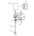
図1に示すように、高周波処置具としてのバイポーラ鉗子1は、生体組織を把持、凝固及び切開するための処置部2、挿入部3及び操作部4とから構成されている。バイポーラ鉗子1は電気コード5を介して高周波焼灼電源装置6に接続されており、この高周波焼灼電源装置6はフットスイッチケーブル7を介してフットスイッチ8に接続されている。
【0012】
操作部4には、図2及び図9に示すように、挿入部3を構成するシース9の基端部に固定された固定側ハンドル10と、この固定側ハンドル10に枢支軸11を介して回動自在に設けられた可動側ハンドル12が設けられている。シース9の内部には凝固ジョー可動シャフト13及び切開ブレード可動シャフト14が軸方向に進退自在に挿入されている。
【0013】
凝固ジョー可動シャフト13の基端部はシース9の基端部より後方に突出し、可動側ハンドル12と連結されている。切開ブレード可動シャフト14の基端部はシース9に対して進退自在に嵌合された切開ブレード可動ガイド15に連結されている。切開ブレード可動ガイド15には切開ブレード操作レバー16及び切開電流通電端子17が設けられている。
【0014】
凝固ジョー可動シャフト13の基端部には第1の凝固電流通電端子18が設けられ、シース9の基端部には第2の凝固電流通電端子19が設けられている。そして、これら切開電流通電端子17、第1及び第2の凝固電流通電端子18,19は、図1に示すように電気コード5に接続されている。
【0015】
次に、処置部2について説明すると、図3〜図8に示すように構成されている。
【0016】
シース9の先端部における左右両側部には前方に突出する支持部材20が固定されている。この一対の支持部材20間には枢支ピン21が架設され、この枢支ピン21には絶縁チューブ22が回転自在に嵌合されている。
【0017】
一対の支持部材20間における枢支ピン21には絶縁チューブ22を介して第1の凝固ジョー23と第2の凝固ジョー24の基端部が回動自在に枢支されている。
【0018】
また、前記凝固ジョー可動シャフト13の先端部には連結部材25が固定され、この連結部材25にはこれと直交する方向に枢支ピン26が回転自在に設けられ、この枢支ピン26には絶縁チューブ27が嵌合されている。枢支ピン26の中間部には第1のリンク28の基端部が固定され、両端部には第2のリンク29の基端部が固定されている。そして、第1のリンク28の先端部は第1の凝固ジョー23の基端部と連結ピン30で回動自在に連結されている。第2のリンク29の先端部は第2の凝固ジョー24の基端部と連結ピン31で回動自在に連結されている。
【0019】
従って、前記凝固ジョー可動シャフト13の前進動作によって第1と第2のリンク28,29が開く方向に回動して第1と第2の凝固ジョー23,24が枢支ピン21を支点として開き、凝固ジョー可動シャフト13の後退動作によって第1と第2のリンク28,29が閉じる方向に回動して第1と第2の凝固ジョー23,24が枢支ピン21を支点として閉じるようになっている。
【0020】
第1と第2の凝固ジョー23,24は平面視で、細長いU字状に形成され、先端部に湾曲部23a,24aが形成され、幅方向の中間部には前後方向に細長い空間部23b,24bが設けられている。
【0021】
さらに、第1の凝固ジョー23の下面及び内側面は絶縁材32によって覆われ、第2の凝固ジョー24の上面及び内側面は絶縁材33によって覆われている。そして、第1と第2の凝固ジョー23,24の外側面及び接合面が露出している。絶縁材32,33は、例えばアルミナ、ジルコニア等のセラミック材を貼り合せたものであるが、これ以外の絶縁材をコーティングしてもよい。
【0022】
また、前記第1と第2の凝固ジョー23,24の空間部23b,24bには偏平板状で、先端部が鋭利な切開部34aを有する切開ブレード34が設けられ、この切開ブレード34の基端側が絶縁チューブ22を介して枢支ピン21に回動自在に枢支されている。切開ブレード34の基端部は後方に向かって斜めに傾斜しており、この基端部には長穴35が設けられている。
【0023】
切開ブレード34の長穴35には前記切開ブレード可動シャフト14の先端部に設けられた係合子36がスライド自在に係合している。そして、切開ブレード可動シャフト14の前進動作によって係合子36が長穴35内をスライドしながら前方に押圧することにより、切開ブレード34が枢支ピン21を支点として上方へ回動し、第2の凝固ジョー24の空間部24b方向に退避し、切開ブレード可動シャフト14の後退動作によって係合子36が長穴35内をスライドしながら後方へ引くことにより、切開ブレード34が枢支ピン21を支点として下方へ回動し、第1の凝固ジョー23の空間部23b方向に進入するようになっている。
【0024】
また、第1の凝固ジョー23は第1のリンク28、連結部材25及び凝固ジョー可動シャフト13等の導電性部材を介して第1の凝固電流通電端子18に的に接続され、第2の凝固ジョー24はシース9等の導電性部材を介して第2の凝固電流通電端子19に電気的に接続されている。さらに、切開ブレード34は切開ブレード可動シャフト14等の導電性部材を介して切開電流通電端子17に電気的に接続されている。
【0025】
次に、第1の実施形態の作用について説明する。
【0026】
前述のように構成されたバイポーラ鉗子1によれば、まず、固定側ハンドル10と可動側ハンドル12に手指を掛け、可動側ハンドル12を図2のB方向に回動させると,凝固ジョー可動シャフト13がシース9内を前進する。
【0027】
従って、第1と第2のリンク28,29が開く方向に回動して第1と第2の凝固ジョー23,24が枢支ピン21を支点として開く。この状態で、生体組織Xの凝固・切開部位に第1の凝固ジョー23と第2の凝固ジョー24を位置決めする。
【0028】
次に、可動側ハンドル12を図2のA方向に回動させると,凝固ジョー可動シャフト13がシース9内を後退するため、第1と第2のリンク28,29が閉じる方向に回動して第1と第2の凝固ジョー23,24が枢支ピン21を支点として閉じ、図10(a)に示すように生体組織Xの凝固・切開部位を把持する。さらに,この操作と同時にフットスイッチ8を操作して高周波焼灼電源装置6から第1の凝固ジョー23と第2の凝固ジョー24との間に凝固電流を流すと、図11(a)に示すように生体組織Xに凝固電流が流れて凝固される。
【0029】
生体組織Xの凝固が完了した後,フットスイッチ8を操作して高周波焼灼電源装置6から切開ブレード34と第1の凝固ジョー23との間に切開電流を流すとともに、切開ブレード操作レバー16に手指を掛け、図2の矢印C方向に引っ張る。
【0030】
すると、切開ブレード可動シャフト14がシース9内を後退し、係合子36が長穴35内をスライドしながら後方へ引くため、切開ブレード34が枢支ピン21を支点として下方へ回動し、図10(b)に示すように第2の凝固ジョー24の空間部24bから第1の凝固ジョー23の空間部23b方向に進入し、図11(b)に示すように生体組織Xの凝固された部位は切開ブレード34と切開電流によって切開される。
【0031】
このとき、第1と第2の凝固ジョー23,24の切開ブレード34が通過する電極表面は絶縁材32,33によって覆われているため、切開ブレード34の電極に切開電流が集中し、電流密度が高く、切開が迅速かつ確実に行なえ、切開性能が向上するという効果がある。
【0032】
ここで、比較例について説明すると、図11(c)に示すように、第1及び第2の凝固ジョー23,24に絶縁材がなく、電極表面が露出していると、切開ブレード34が第1の凝固ジョー23を通過する時点で切開ブレード34の切開部に切開電流が集中しにくく、切開がスムーズに行なわれず、切開性能が悪いという問題がある。
【0033】
なお、前記実施形態においては、切開ブレード34は、その電極表面全体が露出しているが、切開部34aを除き、電極表面全体を絶縁材でコーティングすることにより、切開電流を一層集中させることができる。
【0034】
前記実施の形態によれば,次のような構成が得られる。
【0035】
(付記1)互いに開閉する一対の凝固ジョー及び切開ブレードを有し、生体組織を凝固・切開操作できる処置部を備えた高周波処置具において、前記少なくとも一方の凝固ジョーにおける前記切開ブレードの通過部の電極表面を絶縁材で構成したことを特徴とする高周波処置具。
【0036】
(付記2)前記絶縁材は、コーティングされていることを特徴とする付記1記載の高周波処置具。
【0037】
(付記3)前記凝固ジョーは、その長手方向の略全長に亘って切開ブレードの通過部を有し、この通過部の電極表面が絶縁材で覆われていることを特徴とする付記1記載の高周波処置具。
【0038】
(付記4) 互いに開閉する一対の凝固ジョー及び切開ブレードを有し、生体組織を凝固・切開操作できる処置部を備えた高周波処置具において、前記切開ブレードにおける凝固ジョーを通過する際に該凝固ジョーと対向する個所の電極表面を絶縁材で構成したことを特徴とする高周波処置具。
【0039】
【発明の効果】
以上説明したように、この発明によれば、生体組織を把持した一対の凝固ジョー間に凝固電流を通電して生体組織を凝固した後、切開電流を流した切開ブレードが凝固ジョーを通過して切開する際に、凝固ジョーにおける切開ブレードの通過部の電極表面が絶縁材によって覆われているため、切開ブレードにおける切開電流が集中し、電流密度が高くなり、切開性能が向上するという効果がある。
【図面の簡単な説明】
【図1】 この発明の第1の実施形態を示し、高周波処置具システムの全体構成図。
【図2】 同実施形態の高周波処置具の側面図。
【図3】 同実施形態の処置部の縦断側面図。
【図4】 図3のA−A線に沿う断面図。
【図5】 図4のB−B線に沿う断面図。
【図6】 図4のC−C線に沿う断面図。
【図7】 図4のD−D線に沿う断面図。
【図8】 図3のE−E線に沿う断面図。
【図9】 同実施形態の操作部の縦断側面図。
【図10】 同実施形態を示し、(a)は凝固状態の側面図、(b)は切開状態の側面図。
【図11】 同実施形態を示し、(a)〜(c)は作用説明図。
【符号の説明】
1…バイポーラ鉗子
2…処置部
3…挿入部
4…操作部
23…第1の凝固ジョー
24…第2の凝固ジョー
32,33…絶縁材
34…切開ブレード [0001]
BACKGROUND OF THE INVENTION
The present invention relates to a high-frequency treatment instrument that can be inserted into a body cavity of a living body to coagulate and cut a living tissue.
[0002]
[Prior art]
In general, there is known a bipolar forceps provided with jaws as a pair of grasping members for grasping a living tissue, and electrodes for high-frequency energization arranged on each jaw. When the bipolar forceps are used, the living tissue to be treated is gripped between the pair of jaws, and a high-frequency current is passed between the electrodes of each jaw to coagulate the living tissue between the jaws. .
[0003]
This type of bipolar forceps is generally used for various cases such as hemostasis of blood vessels contained in living tissue, lesions on the surface layer of living tissue, cauterization of bleeding points, occlusion of fallopian tubes for the purpose of contraception. Bipolar forceps are used for hemostasis of blood vessels and occlusion of the fallopian tube, and can coagulate a living tissue to be treated by a patient, and can incise the coagulated living tissue. ing.
[0004]
Conventionally, as a high-frequency treatment instrument, for example, JP-A-9-108234 is known. This high-frequency treatment instrument is provided with a pair of coagulation jaws and a knife blade in the treatment portion at the distal end, and after the living tissue is grasped and coagulated by the pair of coagulation jaws, the knife blade is slid to make an incision. The outer surface excluding the gripping surface of the solidified jaw is covered with an insulating layer.
[0005]
[Problems to be solved by the invention]
However, in Japanese Patent Laid-Open No. 9-108234 described above, in order to accelerate the coagulation of a living tissue, the outer surface except the gripping surface of the coagulation jaw is covered with an insulating layer, and the incision is performed by sliding a knife blade. There is a risk of incision even though coagulation is not sufficient.
[0006]
The present invention has been made paying attention to the above circumstances, and an object of the present invention is to provide a high-frequency treatment instrument capable of improving incision performance by concentrating incision current of an incision blade at the time of incision of a living tissue. There is to do.
[0007]
[Means for Solving the Problems]
In order to achieve the above object, the invention according to claim 1 is characterized in that a living tissue is grasped by a pair of coagulation jaws that open and close each other, and a high frequency is applied to the living tissue through a coagulation electrode of the coagulation jaw to coagulate the living tissue. In a high-frequency treatment instrument having a treatment section, a space portion provided in the coagulation jaw and opened on a gripping surface of the coagulation jaw, and a living tissue held in the space portion and grasped by a pair of coagulation jaws at high frequency A high-frequency cutting blade that can be protruded from the opening of the space portion toward a living tissue grasped by a pair of coagulation jaws at the time of incision, and a high-frequency cutting blade passing surface portion in the space portion, and coagulating the coagulation jaw And an insulating material that insulates the high-frequency cutting blade from the electrode side .
The invention according to
[0008]
According to the above configuration, the coagulation current is applied between the pair of coagulation jaws holding the living tissue to coagulate the living tissue, and then the incision blade that passes the incision current passes through the coagulation jaw to make the incision. Since the electrode surface of the passage part of the cutting blade in the jaw is covered with the insulating material, the cutting current in the cutting blade is concentrated and the cutting performance is improved.
[0009]
DETAILED DESCRIPTION OF THE INVENTION
Hereinafter, embodiments of the present invention will be described with reference to the drawings.
[0010]
1 to 11 show a first embodiment, FIG. 1 is an overall configuration diagram of a high-frequency treatment instrument system, FIG. 2 is a side view of the high-frequency treatment instrument, FIG. 3 is a longitudinal side view of a treatment section, and FIG. 3 is a cross-sectional view taken along line AA in FIG. 3, FIG. 5 is a cross-sectional view taken along line BB in FIG. 4, FIG. 6 is a cross-sectional view taken along line CC in FIG. 8 is a cross-sectional view taken along line E-E in FIG. 3, FIG. 9 is a longitudinal side view of the operation unit, FIG. 10A is a side view in a solidified state, and FIG. Side views and FIGS. 11A, 11B, and 11C are explanatory views of operations.
[0011]
As shown in FIG. 1, a bipolar forceps 1 as a high-frequency treatment instrument includes a
[0012]
As shown in FIGS. 2 and 9, the
[0013]
The base end portion of the solidifying jaw
[0014]
A first solidification
[0015]
Next, the
[0016]
[0017]
The proximal end portions of the first solidified
[0018]
Further, a connecting
[0019]
Accordingly, the first and
[0020]
The first and
[0021]
Further, the lower surface and the inner side surface of the first solidified
[0022]
The first and the
[0023]
An engaging
[0024]
The
[0025]
Next, the operation of the first embodiment will be described.
[0026]
According to the bipolar forceps 1 configured as described above, when a finger is put on the fixed
[0027]
Accordingly, the first and
[0028]
Next, when the
[0029]
After coagulation of the living tissue X is completed, the
[0030]
Then, the cutting blade
[0031]
At this time, since the electrode surfaces through which the
[0032]
Here, a comparative example will be described. As shown in FIG. 11C, when the first and second solidified
[0033]
In the above embodiment, the
[0034]
According to the embodiment, the following configuration is obtained.
[0035]
(Supplementary note 1) In a high-frequency treatment instrument having a pair of coagulation jaws and an incision blade that open and close each other, and having a treatment unit capable of coagulating and incising a living tissue, the passage of the incision blade in the at least one coagulation jaw A high-frequency treatment instrument characterized in that the electrode surface is made of an insulating material.
[0036]
(Additional remark 2) The said high-frequency treatment tool of Additional remark 1 characterized by the above-mentioned.
[0037]
(Additional remark 3) The said coagulation jaw has the passage part of an incision blade over the substantially full length of the longitudinal direction, and the electrode surface of this passage part is covered with the insulating material of the additional remark 1 characterized by the above-mentioned. High frequency treatment tool.
[0038]
(Additional remark 4) In the high frequency treatment tool which has a treatment part which has a pair of coagulation jaws and an incision blade which open and close mutually, and can coagulate and incise a living tissue, when the coagulation jaw passes through the coagulation jaw in the incision blade A high-frequency treatment instrument characterized in that an electrode surface at a location facing the electrode is made of an insulating material.
[0039]
【The invention's effect】
As described above, according to the present invention, after a coagulation current is passed between a pair of coagulation jaws holding a living tissue to coagulate the living tissue, the incision blade that passes the incision current passes through the coagulation jaw. At the time of incision, since the electrode surface of the passing portion of the incision blade in the coagulation jaw is covered with an insulating material, the incision current in the incision blade is concentrated, the current density is increased, and the incision performance is improved. .
[Brief description of the drawings]
FIG. 1 is an overall configuration diagram of a high-frequency treatment instrument system according to a first embodiment of the present invention.
FIG. 2 is a side view of the high-frequency treatment tool of the same embodiment.
FIG. 3 is a longitudinal side view of the treatment section of the embodiment.
4 is a cross-sectional view taken along line AA in FIG.
FIG. 5 is a cross-sectional view taken along line BB in FIG.
6 is a cross-sectional view taken along the line CC of FIG.
7 is a cross-sectional view taken along the line DD of FIG.
8 is a cross-sectional view taken along line EE of FIG.
FIG. 9 is a longitudinal side view of the operation unit of the embodiment.
FIG. 10 shows the same embodiment, (a) is a side view in a solidified state, and (b) is a side view in an incised state.
FIG. 11 shows the same embodiment, and (a) to (c) are operation explanatory views.
[Explanation of symbols]
DESCRIPTION OF SYMBOLS 1 ...
Claims (2)
上記凝固ジョーに設けられ、該凝固ジョーにおける把持面に開口した空間部と、
この空間部内に収納され、一対の凝固ジョーにより把持した生体組織を高周波で切開するときに一対の凝固ジョーにより把持した生体組織に向けて上記空間部の開口から突き出し可能である高周波切開用ブレードと、
上記空間部における高周波切開ブレード通過表面部を覆い、上記凝固ジョーの凝固電極側から高周波切開ブレードを絶縁する絶縁材と、
を具備したことを特徴とする高周波処置具。In a high-frequency treatment instrument provided with a treatment section that grips a living tissue with a pair of coagulation jaws that open and close each other, and energizes the living tissue through a coagulation electrode of the coagulation jaw to coagulate the living tissue .
A space provided in the coagulation jaw and opened to a gripping surface of the coagulation jaw;
A high-frequency incision blade housed in the space and capable of protruding from the opening of the space toward the biological tissue grasped by the pair of coagulation jaws when the biological tissue grasped by the pair of coagulation jaws is incised at high frequency; ,
An insulating material that covers the high-frequency cutting blade passing surface portion in the space, and insulates the high-frequency cutting blade from the coagulation electrode side of the coagulation jaw;
A high-frequency treatment instrument comprising:
Priority Applications (1)
| Application Number | Priority Date | Filing Date | Title |
|---|---|---|---|
| JP2000289472A JP4436552B2 (en) | 2000-09-22 | 2000-09-22 | High frequency treatment tool |
Applications Claiming Priority (1)
| Application Number | Priority Date | Filing Date | Title |
|---|---|---|---|
| JP2000289472A JP4436552B2 (en) | 2000-09-22 | 2000-09-22 | High frequency treatment tool |
Publications (3)
| Publication Number | Publication Date |
|---|---|
| JP2002095676A JP2002095676A (en) | 2002-04-02 |
| JP2002095676A5 JP2002095676A5 (en) | 2006-11-24 |
| JP4436552B2 true JP4436552B2 (en) | 2010-03-24 |
Family
ID=18772867
Family Applications (1)
| Application Number | Title | Priority Date | Filing Date |
|---|---|---|---|
| JP2000289472A Expired - Fee Related JP4436552B2 (en) | 2000-09-22 | 2000-09-22 | High frequency treatment tool |
Country Status (1)
| Country | Link |
|---|---|
| JP (1) | JP4436552B2 (en) |
Families Citing this family (5)
| Publication number | Priority date | Publication date | Assignee | Title |
|---|---|---|---|---|
| JP4459814B2 (en) * | 2002-10-04 | 2010-04-28 | コヴィディエン アクチェンゲゼルシャフト | Electrode assembly for sealing and cutting tissue and method for performing sealing and cutting tissue |
| GB2408936B (en) * | 2003-12-09 | 2007-07-18 | Gyrus Group Plc | A surgical instrument |
| DE102009049401B4 (en) * | 2009-08-20 | 2023-09-28 | Erbe Elektromedizin Gmbh | Electrosurgical forceps |
| EP2621389B1 (en) * | 2010-10-01 | 2015-03-18 | Applied Medical Resources Corporation | Electrosurgical instrument with jaws and with an electrode |
| US8968309B2 (en) * | 2011-11-10 | 2015-03-03 | Covidien Lp | Surgical forceps |
-
2000
- 2000-09-22 JP JP2000289472A patent/JP4436552B2/en not_active Expired - Fee Related
Also Published As
| Publication number | Publication date |
|---|---|
| JP2002095676A (en) | 2002-04-02 |
Similar Documents
| Publication | Publication Date | Title |
|---|---|---|
| JP3986126B2 (en) | Endoscopic surgical instrument | |
| EP0795301B1 (en) | Bipolar cutting and coagulation instrument | |
| JP4981505B2 (en) | Treatment device | |
| JP4315557B2 (en) | Medical treatment tool | |
| JP3384750B2 (en) | High frequency treatment tool | |
| US7052496B2 (en) | Instrument for high-frequency treatment and method of high-frequency treatment | |
| JP5636449B2 (en) | High frequency treatment tool | |
| US6736813B2 (en) | High-frequency treatment tool | |
| CN103099670B (en) | surgical forceps | |
| EP2040634B1 (en) | Surgical sealing and cutting apparatus | |
| JP3255885B2 (en) | Medical treatment tools | |
| US20020013583A1 (en) | Bipolar surgical instruments having focused electrical fields | |
| JP2000139943A (en) | High-frequency treating instrument | |
| JPH1147150A (en) | Endoscopic surgery appliance | |
| JP3610306B2 (en) | High frequency treatment tool | |
| CN103479425B (en) | Possesses the electrosurgery dissector of heat management | |
| JPH11267132A (en) | High-frequency treatment tool | |
| JP4059665B2 (en) | High frequency treatment tool | |
| JPH1033551A (en) | Bipolar forceps | |
| JP4436552B2 (en) | High frequency treatment tool | |
| JP2001170070A (en) | Medical treatment instrument | |
| JP2001095813A (en) | Bipolar coagulation incision appliance | |
| JP4021052B2 (en) | Treatment tool | |
| JP2001061848A (en) | High frequency treatment apparatus | |
| JP6841029B2 (en) | Medical high frequency treatment tool |
Legal Events
| Date | Code | Title | Description |
|---|---|---|---|
| A521 | Written amendment |
Free format text: JAPANESE INTERMEDIATE CODE: A523 Effective date: 20061005 |
|
| A621 | Written request for application examination |
Free format text: JAPANESE INTERMEDIATE CODE: A621 Effective date: 20061005 |
|
| A131 | Notification of reasons for refusal |
Free format text: JAPANESE INTERMEDIATE CODE: A131 Effective date: 20090915 |
|
| A521 | Written amendment |
Free format text: JAPANESE INTERMEDIATE CODE: A523 Effective date: 20091113 |
|
| TRDD | Decision of grant or rejection written | ||
| A01 | Written decision to grant a patent or to grant a registration (utility model) |
Free format text: JAPANESE INTERMEDIATE CODE: A01 Effective date: 20091208 |
|
| A01 | Written decision to grant a patent or to grant a registration (utility model) |
Free format text: JAPANESE INTERMEDIATE CODE: A01 |
|
| A61 | First payment of annual fees (during grant procedure) |
Free format text: JAPANESE INTERMEDIATE CODE: A61 Effective date: 20091228 |
|
| R151 | Written notification of patent or utility model registration |
Ref document number: 4436552 Country of ref document: JP Free format text: JAPANESE INTERMEDIATE CODE: R151 |
|
| FPAY | Renewal fee payment (event date is renewal date of database) |
Free format text: PAYMENT UNTIL: 20130108 Year of fee payment: 3 |
|
| FPAY | Renewal fee payment (event date is renewal date of database) |
Free format text: PAYMENT UNTIL: 20140108 Year of fee payment: 4 |
|
| S531 | Written request for registration of change of domicile |
Free format text: JAPANESE INTERMEDIATE CODE: R313531 |
|
| R350 | Written notification of registration of transfer |
Free format text: JAPANESE INTERMEDIATE CODE: R350 |
|
| LAPS | Cancellation because of no payment of annual fees |