EP3011506B1 - System and method for single-frame based super resolution interpolation for digital cameras - Google Patents
System and method for single-frame based super resolution interpolation for digital cameras Download PDFInfo
- Publication number
- EP3011506B1 EP3011506B1 EP14813700.3A EP14813700A EP3011506B1 EP 3011506 B1 EP3011506 B1 EP 3011506B1 EP 14813700 A EP14813700 A EP 14813700A EP 3011506 B1 EP3011506 B1 EP 3011506B1
- Authority
- EP
- European Patent Office
- Prior art keywords
- edge
- image
- resolution
- block
- enhanced image
- Prior art date
- Legal status (The legal status is an assumption and is not a legal conclusion. Google has not performed a legal analysis and makes no representation as to the accuracy of the status listed.)
- Active
Links
Images


Classifications
-
- G—PHYSICS
- G06—COMPUTING OR CALCULATING; COUNTING
- G06T—IMAGE DATA PROCESSING OR GENERATION, IN GENERAL
- G06T3/00—Geometric image transformations in the plane of the image
- G06T3/40—Scaling of whole images or parts thereof, e.g. expanding or contracting
- G06T3/4053—Scaling of whole images or parts thereof, e.g. expanding or contracting based on super-resolution, i.e. the output image resolution being higher than the sensor resolution
-
- G—PHYSICS
- G06—COMPUTING OR CALCULATING; COUNTING
- G06T—IMAGE DATA PROCESSING OR GENERATION, IN GENERAL
- G06T3/00—Geometric image transformations in the plane of the image
- G06T3/40—Scaling of whole images or parts thereof, e.g. expanding or contracting
-
- G—PHYSICS
- G06—COMPUTING OR CALCULATING; COUNTING
- G06T—IMAGE DATA PROCESSING OR GENERATION, IN GENERAL
- G06T3/00—Geometric image transformations in the plane of the image
- G06T3/40—Scaling of whole images or parts thereof, e.g. expanding or contracting
- G06T3/4007—Scaling of whole images or parts thereof, e.g. expanding or contracting based on interpolation, e.g. bilinear interpolation
-
- G—PHYSICS
- G06—COMPUTING OR CALCULATING; COUNTING
- G06T—IMAGE DATA PROCESSING OR GENERATION, IN GENERAL
- G06T3/00—Geometric image transformations in the plane of the image
- G06T3/40—Scaling of whole images or parts thereof, e.g. expanding or contracting
- G06T3/403—Edge-driven scaling; Edge-based scaling
-
- H—ELECTRICITY
- H04—ELECTRIC COMMUNICATION TECHNIQUE
- H04N—PICTORIAL COMMUNICATION, e.g. TELEVISION
- H04N23/00—Cameras or camera modules comprising electronic image sensors; Control thereof
- H04N23/80—Camera processing pipelines; Components thereof
- H04N23/815—Camera processing pipelines; Components thereof for controlling the resolution by using a single image
-
- G—PHYSICS
- G06—COMPUTING OR CALCULATING; COUNTING
- G06T—IMAGE DATA PROCESSING OR GENERATION, IN GENERAL
- G06T2207/00—Indexing scheme for image analysis or image enhancement
- G06T2207/20—Special algorithmic details
- G06T2207/20172—Image enhancement details
- G06T2207/20192—Edge enhancement; Edge preservation
-
- G—PHYSICS
- G06—COMPUTING OR CALCULATING; COUNTING
- G06T—IMAGE DATA PROCESSING OR GENERATION, IN GENERAL
- G06T2207/00—Indexing scheme for image analysis or image enhancement
- G06T2207/20—Special algorithmic details
- G06T2207/20212—Image combination
-
- G—PHYSICS
- G09—EDUCATION; CRYPTOGRAPHY; DISPLAY; ADVERTISING; SEALS
- G09G—ARRANGEMENTS OR CIRCUITS FOR CONTROL OF INDICATING DEVICES USING STATIC MEANS TO PRESENT VARIABLE INFORMATION
- G09G2340/00—Aspects of display data processing
- G09G2340/04—Changes in size, position or resolution of an image
- G09G2340/045—Zooming at least part of an image, i.e. enlarging it or shrinking it
Definitions
- the present invention relates to systems and methods for single-frame based super resolution interpolation for digital cameras.
- Digital cameras use various systems to enable photographers to capture images of objects at long distances.
- Optical zoom systems use one or more zoom lenses that may be adjusted to narrow the field of visible radiation incident on the photo-detectors of the digital camera.
- the narrower field of visible radiation incident on the photo-detectors magnifies the captured image, albeit with a narrower field of view, without the introduction of significant image aberrations.
- digital zoom systems process the image, or a subset of the image, to increase its resolution to create an effect similar to optical zoom (i.e., a magnified narrower field of view).
- Digital zoom systems generally produce significant undesirable image aberrations relative to optical zoom systems.
- digital zoom systems may introduce aliasing (i.e., jagged diagonal edges), blurring, and/or haloing into the image.
- the aberrations introduced during digital zoom process occur primarily at or around the edges of objects in the image.
- Document US 2006/290950 A1 discloses an image enhancement system and method for generating high-resolution bitmaps from low-resolution bitmaps.
- An original, low-resolution bitmap is magnified to form a magnified image and high contrast edges are extracted from the magnified image.
- the magnified image is transformed into overlapping image patches which are analyzed by performing connected components analysis to determine foreground and background regions using said extracted high contrast edges located by the edge detector. Once the foreground and background regions have been determined, the contrast of the center pixel in each of the plurality of image patches is enhanced based on whether the region is a foreground or a background region.
- the image enhancement system and method of the invention combines the luminance of the enhanced output pixels with the color values produced by the magnification algorithm used to generate the magnified image resulting in a high-resolution bitmap from the contrast-enhanced pixels.
- Document EP 2209087 A1 discloses an apparatus which obtains a high-resolution image, including: a scaler to scale an input image and generate a first output image, a high frequency component extraction unit to extract a first high frequency component of the first output image from the input image, a high frequency component generation unit to generate a second high frequency component of the first output image based on the first high frequency component, and an image synthesis unit to synthesize the first output image and the second high frequency component and generate a second output image.
- Document US 2010/259653 A1 discloses an image processing device for super-resolution processing wherein an input low-resolution image is first processed for edge enhancement and then super-resolution processing is applied to generate an output high-resolution image.
- Embodiments of the present invention relate to single-frame based super resolution interpolation for digital cameras.
- digital camera used herein includes, but is not limited to, dedicated cameras as well as camera functionality performed by any electronic device (e.g., mobile phones, personal digital assistants, etc.).
- the methods and systems described herein may be applied to a plurality of images arranged in a time sequence (e.g., a video stream).
- module is interchangeable with the term “block” and is meant to include implementations of processes and/or functions in software, hardware, or a combination of software and hardware.
- the single-frame based super resolution interpolation system and method digitally zoom an image, or any portion of the image, without producing significant image aberrations in the output digitally zoomed image.
- Digitally zooming an image causes significant aberrations particularly to the edges of objects in the image. For example, the edges in digitally zoomed images may appear jagged from aliasing. Accordingly, in some embodiments, the systems and methods provided improve the quality of the edges in the super resolution process to produce a high quality digitally zoomed image.
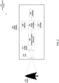
- FIG. 1 illustrates an example system for super resolution image processing.
- the super resolution image processing system 100 of FIG. 1 includes a super resolution engine 110 that receives an image 102 and performs image processing on the received image to produce a digitally zoomed image 104.
- the super resolution engine 110 includes multiple functional blocks or modules including an image region selection block 112 that selects at least a portion of the image 102 and provides an image region 106, a resolution enhancement block 114 that enhances the resolution of the portion of the image and provides a resolution enhanced image region 108, and an edge enhancement block 116 that enhances edges in the enhanced image region and provides the digitally zoomed image 104.
- the input to the super resolution engine 110 is an image 102.
- the image comprises a plurality of pixels represented by one or more two dimensional matrices.
- Each element in the matrices represents information regarding a specific pixel location in the image.
- the location (10, 10) in a first, second, and third two dimensional matrix may represent data associated with a pixel at the (10,10) location in the image.
- Each of the one or more matrices may represent a set of intensities associated with the image in a given dimension.
- each pixel in the image is represented by a three-dimensional vector.
- the image is represented by a first two dimensional matrix for the first dimension, a second two dimensional matrix for the second dimension, and a third two dimensional matrix for the third dimension. It is appreciated that each pixel may be represented by any number of dimensions or any number of matrices.
- the image is represented by three two dimensional matrices consistent with a YUV color space.
- the YUV color space is composed of three distinct components Y, U, and V where each two dimensional matrix represents a specific component of the YUV space.
- the Y component is the luminance component that relates to the brightness of the image.
- the U and V components are chrominance components that relate to the specific color of the image.
- Each pixel in an image is represented by a vector in the YUV color space (i.e., some combination of the Y, U, and V components).
- the image is represented by three two dimensional matrices consistent with a RGB color space.
- the RGB color space is also composed of three distinct components R, G, and B where each two dimensional matrix represents a specific component of the RGB space. All three of the distinct components (i.e., R, G, and B components) are all chrominance components that relate to the specific color of the image. It is appreciated that the image may be represented in any color space and is not limited to the YUV or RGB color spaces.
- the image 102 is input into the super resolution engine 110.
- the super resolution engine 110 executes a variety of processes to output a digitally zoomed image 104.
- the digitally zoomed image is a magnified image region 106.
- the image region 106 may include the entire image or any subset of the image 102. It is appreciated that the processes performed by the super resolution engine 110 do not need to be performed on all of the dimensions of each pixel of the image region 106.
- the pixels in the image region 106 are represented by a vector in the YUV color space. In these embodiments, the processes of the super resolution engine 110 may be performed on any combination dimensions in the YUV color space.
- the processes of the super resolution engine may be performed only on the Y component (i.e., the luminance component) of the image region 106 pixels.
- interpolation processes e.g., bicubic interpolation
- U and V components i.e., the chrominance components
- the various processes performed by the super resolution engine 110 to generate the digitally zoomed image 104 include the processes performed by the image region selection block 112, the resolution enhancement block 114, and the edge enhancement block 116.
- the image region selection block 112 crops the image as appropriate to select an image region 106 of the input image 102 to be digitally zoomed. It is appreciated that the image region selection block 112 is an optional block.
- the super resolution engine 110 may digitally zoom the entire image 102. In other embodiments, the super resolution engine 110 self-selects the entire image 102 or any subset of the image 102 to digitally zoom.
- the resolution enhancement block 114 increases the resolution of the image region 106 to produce an enhanced resolution image region 108.
- the resolution of the image region 106 is increased through interpolation of the image region 106.
- Interpolation is a method of creating new data points between a set of known discrete data points.
- the known data points are the known pixel values (e.g., the Y, U, and/or V channel intensity values for a given pixel).
- the new data points in this embodiment, are the pixels created through interpolation. It is appreciated that the interpolation is preceded by one or more acts to smooth the edges of the image region 106 to improve the quality of the edges in the resolution enhanced image region 108.
- the edge smoothing sharpens the image by shortening the transitions between color and/or brightness changes (i.e., object edges).
- a visual representation of an edge smoothing process is illustrated in the edge smoothing process diagrams 600 with reference to FIG. 6 .
- the super resolution engine 110 may proceed to the edge enhancement block 116.
- the edge enhancement block 116 enhances the edges of objects in the image.
- the interpolation performed in the resolution enhancement block 114 may create a smoothed image that lacks sharp details. Accordingly, the edge enhancement block 116 is capable of extracting and enhancing the edges of the resolution enhanced image region 108.
- the edge enhancement block 116 extracts the edges of the resolution enhanced image region 108. The extracted edges are then added to the resolution enhanced image region 108 to increase the edge detail.
- any combination of the super resolution image processing functional blocks may perform operations in parallel.
- the input image 102 may be divided into a plurality of subsections. Each subsection of the image 102 may be processed individually in parallel. The processed subsections may be combined to form the digitally zoomed image 104. Implementing the super resolution image processing in parallel increases the speed in which the digitally zoomed image 104 can be provided.
- the super resolution engine 110 may take a variety of forms dependent upon the specific application.
- the super resolution engine 110 comprises a series of instructions performed by an image processing system.
- one or more of the blocks or modules 112, 114, and 116 may be implemented in hardware, such as an application-specific integrated circuit (ASIC), system on a chip (SoC), state machine, or a dedicated processor.
- ASIC application-specific integrated circuit
- SoC system on a chip
- state machine or a dedicated processor.
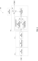
- FIG. 2 illustrates an example image processing system 200 in which super resolution processing can be performed.
- the image processing system 200 of FIG. 2 includes a digital camera 202 that is configured to provide a digital image of a scene 218.
- the digital camera 202 includes an image processor 204, an analog-to-digital converter 206, a memory 208, an interface 210, storage 212, an image sensor 214, and a lens 216.
- the digital camera 202 includes the image processor 204 to implement at least some of the aspects, functions and processes disclosed herein.
- the image processor 204 performs a series of instructions that result in manipulated data.
- the image processor 204 may be any type of processor, multiprocessor or controller. Some exemplary processors include processors with ARM11 or ARM9 architectures.
- the image processor 204 is connected to other system components, including one or more memory devices 208.
- the memory 208 stores programs and data during operation of the digital camera 202.
- the memory 208 may be a relatively high performance, volatile, random access memory such as a dynamic random access memory (“DRAM”) or static memory (“SRAM").
- DRAM dynamic random access memory
- SRAM static memory
- the memory 208 may include any device for storing data, such as a flash memory or other non-volatile storage devices.
- Various examples may organize the memory 208 into particularized and, in some cases, unique structures to perform the functions disclosed herein. These data structures may be sized and organized to store values for particular data and types of data.
- the data storage element 212 includes a writeable nonvolatile, or nontransitory, data storage medium in which instructions are stored that define a program or other object that is executed by the image processor 204.
- the data storage element 212 also may include information that is recorded, on or in, the medium, and that is processed by the image processor 204 during execution of the program. More specifically, the information may be stored in one or more data structures specifically configured to conserve storage space or increase data exchange performance.
- the instructions may be persistently stored as encoded signals, and the instructions may cause the image processor 204 to perform any of the functions described herein.
- the medium may, for example, be optical disk, magnetic disk or flash memory, among others.
- the image processor 204 or some other controller causes data to be read from the nonvolatile recording medium into another memory, such as the memory 208, that allows for faster access to the information by the image processor 204 than does the storage medium included in the data storage element 212.
- the memory may be located in the data storage element 212 or in the memory 208, however, the image processor 204 manipulates the data within the memory, and then copies the data to the storage medium associated with the data storage element 212 after processing is completed.
- a variety of components may manage data movement between the storage medium and other memory elements and examples are not limited to particular data management components. Further, examples are not limited to a particular memory system or data storage system.
- the digital camera 202 also includes one or more interface devices 210 such as input devices, output devices and combination input/output devices.
- Interface devices may receive input or provide output. More particularly, output devices may render information for external presentation. Input devices may accept information from external sources. Examples of interface devices include microphones, touch screens, display screens, speakers, buttons, etc. Interface devices allow the digital camera 202 to exchange information and to communicate with external entities, such as users and other systems.
- the digital camera 202 is shown by way of example as one type of digital camera upon which various aspects and functions may be practiced, aspects and functions are not limited to being implemented on the digital camera 202 as shown in FIG. 2 .
- the digital camera 202 may include specially programmed, special-purpose hardware, such as an application-specific integrated circuit ("ASIC") or a system on a chip (“SoC”) tailored to perform a particular operation disclosed herein.
- ASIC application-specific integrated circuit
- SoC system on a chip
- the digital camera 202 may be incorporated into another electronic device (e.g., mobile phone, personal digital assistant etc.) and is not limited to dedicated digital cameras.
- the lens 216 includes one or more lenses that focus the visible radiation on the image sensor 214. It is appreciated that the lens 216 is not limited to a single physical lens as illustrated in FIG. 2 . In some embodiments, the lens 216 includes a plurality of zoom lenses that enable optical zoom. Optical zoom may be accomplished by narrowing the field of view of the visible radiation incident on the image sensor 214.
- the image sensor 214 may include a two dimensional area of sensors (e.g., photodetectors) that are sensitive to light.
- the photo-detectors of the image sensor 214 in some embodiments, can detect the intensity of the visible radiation in one of two or more individual color and/or brightness components.
- the output of the photo-detectors may include values consistent with a YUV or RGB color space. It is appreciated that other color spaces may be employed by the image sensor 214 to represent the captured image.
- the image sensor 214 outputs an analog signal proportional to the intensity and/or color of visible radiation striking the photo-detectors of the image sensor 214.
- the analog signal output by the image sensor 214 may be converted to digital data by the analog-to-digital converter 206 for processing by the image processor 204.
- the functionality of the analog-to-digital converter 206 is integrated with the image sensor 214.
- the image processor 204 may perform variety of processes to the captured image. These processes may include, but are not limited to, one or more super resolution processes to digitally zoom the captured image.
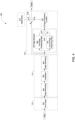
- FIG. 3 illustrates a more detailed functional block diagram of the super resolution image processing system 100 including an image region selection block 112, a resolution enhancement block 114, and an edge enhancement block 116 in accordance with FIG. 1 .
- the super resolution image processing system 300 of FIG. 3 includes a crop image block 302, an edge smoothing block 304, an interpolate block 306, an edge extraction block 307, a fine edge-preserving filter block 308, a course edge-preserving filter block 310, an edge processing function block 312, a white noise block 314, a difference block 316, and a sum block 318.
- any block drawn in dashed lines is an optional block.
- large boxes drawn in dotted lines show the relation between the super resolution image processing system 100 including the image region selection block 112, the resolution enhancement block 114, and the edge enhancement block 116 described with reference to FIG. 1 and the functional blocks shown in FIG. 3 .
- the crop image block 302 illustrates one possible implementation of the image region selection block 112.
- the crop image block 302 crops the image as appropriate to feed into the later functional blocks of the super resolution image processing system 300.
- the crop image block 302 may crop the image responsive to input received through an interface from an external entity (e.g., interface 210 of the digital camera 202).
- the crop image block 302 self-selects an image region 106 and crops the image 102 as appropriate. It is appreciated that the crop image block 302 is an optional block.
- the optional image region selection block 112 is followed by the resolution enhancement block 114.
- the edge smoothing block 304 and the interpolate block 306 illustrate one possible implementation of the resolution enhancement block 114.
- the edge smoothing block 304 smoothes the edges of objects in the image region 106.
- the edge of an object in an image may be characterized by a set of contiguous pixels where an abrupt change of intensity values occurs.
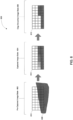
- edge smoothing process diagrams 600 A visual representation of an edge smoothing process is illustrated by the edge smoothing process diagrams 600 with reference to FIG. 6 .
- the edge smoothing process diagrams 600 of FIG. 6 includes an object 608 within the field of view of a pixel matrix 610 that proceeds through a pre-captured image state 602, a captured image state 604, and an edge smoothed image state 606.
- the pre-captured image state 602 illustrates an object 608 in the field of view of a pixel matrix 610.
- the edges of the object 608 cross through a plurality of pixels in the pixel matrix.
- the captured image state 604 of the pixel matrix 610 illustrates the effect of capturing an image of an object with edges crossing through multiple pixels.
- the third row of pixels from the top illustrates the edge blurring effect that occurs when an image is captured by a digital camera (e.g., digital camera 202).
- the pixels in the third row from the top get darker moving from left to right proportional to the area of the pixel that was covered by the object.
- the edge smoothing process that occurs between the image captured state 604 and the edge smoothed image state 606 sharpens the image by eliminating some or all of the transition pixels.
- the elimination of transition pixels is shown in the third row of the pixel matrix 610 in the edge smoothed image state 606.
- the degree of the transition i.e., the amount of transition pixels remaining in the image region
- the edge smoothing block 304 may be any pertinent edge smoothing or edge-preserving filter.
- the edge smoothing filter is the edge preserving noise reduction filter described in co-pending U.S. Application Serial No. 13/160,775, titled ADVANCED NOISE REDUCTION IN DIGITAL CAMERAS, filed June 15, 2011 (hereinafter the "'775 application"). It should be appreciated that embodiments of the present invention are not limited to any particular type of edge smoothing or edge preserving filter, as various types of filters may be used.
- the edge smoothing block is followed by the interpolate block 306.
- the interpolate block may compute a new pixel matrix at a higher resolution based on the input pixel matrix.
- the interpolation block analyzes a closest set of pixels from the input image pixel matrix to determine corresponding new pixel values in the new pixel matrix.
- the specific process that is used to perform the interpolation may be consistent with a variety of methods including, but not limited to, bicubic interpolation, bilinear interpolation, nearest neighbor interpolation, spline interpolation, or sinc interpolation.
- the resolution enhancement block 114 is followed by the edge enhancement block 116.
- the edge enhancement block 116 in some embodiments, is illustrated by the edge extraction block 307, the fine edge-preserving filter 308, the course edge-preserving filter 310, the edge processing function block 312, the difference block 316, and the sum block 318.
- the fine edge-preserving filter 308 and the course edge-preserving filter 310 are edge sensitive filters of different strengths.
- the fine edge preserving filter 308 is a weaker edge filter than the course edge-preserving filter 310. It is appreciated that the fine edge-preserving filter 308 may or may not be the same type of edge preserving filter as the course edge-preserving filter 310.
- the output of the course edge preserving filter 310 is subtracted from the output of the fine edge preserving filter 308 in difference block 316.
- the output of the difference block 316 contains only the edges of the resolution enhanced image region 108.
- the combination of the fine edge-preserving filter 308, the course edge-preserving filter 310 and the difference block 318 may thus form the edge extraction block 307. It is appreciated that the specific method to obtain the edges of the resolution enhanced image region 108 may be altered. For example, a plurality of edge preserving filters of various strengths may be combined in a linear fashion to generate a similar resultant output (i.e., the edges of the image). In addition, a single filter that targets the edges of the images may also be used.
- the fine edge-preserving filter 308 and the course edge-preserving filter 310 can be the edge preserving noise reduction filters described in the '775 application. It is appreciated that any combination of the edge-preserving filters may be selectable, for example, based on input or preferences received from a user of the system.
- the image edges from the difference block 316 may then be processed by the edge processing function block 312.
- the edge processing function block may be any function, linear or otherwise, that enhances the resolution enhanced image 106 edges.
- the edge processing function block may be implemented, for example, with a lookup table (LUT).
- the edge processing function block 312 is a multiplier that amplifies or attenuates the edges.
- the edge processing function block 312 may receive input from a user through a user interface.
- the user interface may have configurable settings regarding the level of detail in the digitally zoomed image 104.
- the edge processing function block 312 may increase the multiplier responsive to a higher detail level setting or decrease the multiplier responsive to a lower detail level setting. It is appreciated that the edge processing function block 312 is an optional function.
- the output of the difference block 312 may be directly connected to the summation block 318.
- the summation block 318 combines the resolution enhanced image region 106 with the edges of the resolution enhanced image region 106 to form a digitally zoomed image 104.
- the addition of the edges of the resolution enhanced image region 106 to the resolution enhanced image region 106 increases the detail of the edges that may have undergone some level of distortion in the resolution enhancement block 114.
- the summation block 318 may also combine white noise from the white noise block 314 with the digitally zoomed image 104.
- the addition of white noise to the digitally zoomed image 104 gives the appearance of high resolution noise in the digitally zoomed image 104 rather than amplified low resolution noise.
- the intensity of white noise added may vary.
- the amount of white noise added to the image is computed responsive to the camera settings when the image was taken (e.g., ISO, aperture, or shutter speed). It is appreciated that the addition of white noise, and consequently the white noise block 314, is optional.
- the white noise from the white noise module may be combined with the resolution enhanced image region 106.
- FIG. 4 illustrates an alternative functional block diagram of the super resolution image processing system 100 including an image region selection block 112, a resolution enhancement block 114, and an edge enhancement block 116 in accordance with FIG. 1 .
- the super resolution image processing system 400 of FIG. 4 includes a crop image block 302, edge smoothing blocks 304 and 404, an interpolation block 306, an edge extraction block 307, a fine edge-preserving filter block 308, a course edge-preserving filter block 310, an edge processing function block 312, a white noise block 314, a difference block 316, and a sum block 318.
- any block drawn in dashed lines is an optional block.
- large boxes drawn in dotted lines show the relation between the processes described with reference to FIG. 1 and the functional blocks shown in FIG. 4 .
- the image region selection block 112 and the edge enhancement block 116 implemented by the crop image block 302, the edge extraction block 307, the fine edge preserving filter 308, the course edge-preserving filter 310, the edge processing function block 312, the difference block 316, and the sum block 318 are similar to that described with reference FIG. 3 above.
- the resolution enhancement block 114 that is implemented in the embodiment depicted in FIG. 4 by the edge smoothing blocks 304 and 404 in addition to the interpolate block 306 is a variation of the resolution enhancement block 116 described with reference to FIG. 3 .
- the additional edge smoothing block 404 improves the quality of the edges in the resolution enhanced image 106 and consequently the final digitally zoomed image 104.
- the additional cost of the additional edge smoothing block 404 is the additional computation required to perform the additional edge smoothing. It is appreciated that the filter used in the edge smoothing block 404 may, or may not, be constructed to be identical to the edge filter in the edge smoothing block 304. In addition, the summation block 318 may also combine white noise from the white noise block 314 with the digitally zoomed image 104 as described with reference to FIG. 3 .
- FIG. 5 illustrates a further alternative functional block diagram of the super resolution image processing system 100 including an image region selection block 112, are solution enhancement block 114, and an edge enhancement block 116 in accordance with FIG. 1 .
- the super resolution image processing system 500 of FIG. 5 includes a crop image block 302, edge smoothing blocks 304 and 504, interpolation blocks 306 and 406, edge extraction blocks 307 and 507, fine edge-preserving filter blocks 308 and 508, course edge-preserving filter blocks 310 and 410, edge processing function blocks 312 and 512, white noise block 514, difference blocks 316 and 516, and sum blocks 318 and 518.
- any block drawn in dashed lines is an optional block.
- large boxes drawn in dotted lines show the relation between the processes described with reference to FIG. 1 and the functional blocks shown in FIG. 5 .
- the image region selection block 112, resolution enhancement block 114, and the edge enhancement block 116 are similar to that described with reference FIG. 3 above.
- the implementation of the super resolution image processing system in FIG. 5 shows multiple iterations of the resolution enhancement block 114 and the edge enhancement block 116. Multiple iterations of the resolution enhancement block 114 and the edge enhancement block 116 processes increase the detail in the digitally zoomed image 104 at the cost of additional computation. It is appreciated that the resolution enhancement block 114 and the edge enhancement block 116 may be repeated any number of times to achieve the desired level of detail in the digitally zoomed image 104. In one embodiment, the image 102 may need to be digitally zoomed substantially.
- the first iteration of the resolution enhancement block 114 and the edge enhancement block 116 may only digitally zoom the image 102 a fraction of the required total digital zoom.
- the second iteration of the resolution enhancement block 114 and the edge enhancement block 116 may increase the resolution to the desired final digitally zoomed image 104.
- an additional edge smoothing block e.g., edge smoothing block 404 in FIG. 4
- the summation block 518 may also combine white noise from the white noise block 514 with the digitally zoomed image 104 after both iterations of the super resolution processes.
- the super resolution image processing system 100 including the image region selection block 112, the resolution enhancement block 114, and the edge enhancement block 116 may be performed on any combination of the chrominance and/or luminance channels of the image 102.
- the image 102 is in the YUV color space and the super resolution image processing system 100 including the image region selection block 112, the resolution enhancement block 114, and the edge enhancement block 116 are only applied to the luminance channel (i.e., Y channel) of the image 102.
- the U and V channels undergo only interpolation (e.g., bicubic interpolation). This embodiment is of lower computational complexity when compared to performing the super resolution processes on all three channels.
- the loss of quality is minimal, in this embodiment, because the human eye is substantially more sensitive to brightness than color.
- the sensitivity of the photoreceptors that perceive brightness i.e., rods of the human eye
- photoreceptors that perceive color i.e., cones of the human eye
Landscapes
- Engineering & Computer Science (AREA)
- Physics & Mathematics (AREA)
- General Physics & Mathematics (AREA)
- Theoretical Computer Science (AREA)
- Multimedia (AREA)
- Signal Processing (AREA)
- Image Processing (AREA)
- Studio Devices (AREA)
- Editing Of Facsimile Originals (AREA)
Applications Claiming Priority (2)
| Application Number | Priority Date | Filing Date | Title |
|---|---|---|---|
| US13/921,712 US9154698B2 (en) | 2013-06-19 | 2013-06-19 | System and method for single-frame based super resolution interpolation for digital cameras |
| PCT/US2014/042899 WO2014205055A1 (en) | 2013-06-19 | 2014-06-18 | System and method for single-frame based super resolution interpolation for digital cameras |
Publications (3)
| Publication Number | Publication Date |
|---|---|
| EP3011506A1 EP3011506A1 (en) | 2016-04-27 |
| EP3011506A4 EP3011506A4 (en) | 2017-02-15 |
| EP3011506B1 true EP3011506B1 (en) | 2024-11-27 |
Family
ID=52105212
Family Applications (1)
| Application Number | Title | Priority Date | Filing Date |
|---|---|---|---|
| EP14813700.3A Active EP3011506B1 (en) | 2013-06-19 | 2014-06-18 | System and method for single-frame based super resolution interpolation for digital cameras |
Country Status (6)
| Country | Link |
|---|---|
| US (2) | US9154698B2 (enExample) |
| EP (1) | EP3011506B1 (enExample) |
| JP (1) | JP6545670B2 (enExample) |
| KR (1) | KR20160040520A (enExample) |
| CN (1) | CN105339954B (enExample) |
| WO (1) | WO2014205055A1 (enExample) |
Families Citing this family (11)
| Publication number | Priority date | Publication date | Assignee | Title |
|---|---|---|---|---|
| US9154698B2 (en) | 2013-06-19 | 2015-10-06 | Qualcomm Technologies, Inc. | System and method for single-frame based super resolution interpolation for digital cameras |
| US10229478B2 (en) * | 2014-09-26 | 2019-03-12 | Samsung Electronics Co., Ltd. | Image processing apparatus and image processing method |
| TWI576789B (zh) * | 2015-07-13 | 2017-04-01 | 華碩電腦股份有限公司 | 影像處理方法、非暫態電腦可讀取記錄媒體及電子裝置 |
| US10410314B2 (en) * | 2017-04-27 | 2019-09-10 | Apple Inc. | Systems and methods for crossfading image data |
| WO2020191475A1 (en) * | 2019-03-25 | 2020-10-01 | Teledyne Digital Imaging, Inc. | Method for generating a super-resolution image and related device |
| JP7244661B2 (ja) * | 2019-09-20 | 2023-03-22 | 株式会社日立国際電気 | 撮像装置及び画像処理方法 |
| CN110827200B (zh) * | 2019-11-04 | 2023-04-07 | Oppo广东移动通信有限公司 | 一种图像超分重建方法、图像超分重建装置及移动终端 |
| CN111447359B (zh) * | 2020-03-19 | 2021-07-02 | 展讯通信(上海)有限公司 | 数字变焦方法、系统、电子设备、介质及数字成像设备 |
| US20210334975A1 (en) * | 2020-04-23 | 2021-10-28 | Nvidia Corporation | Image segmentation using one or more neural networks |
| CN111340711B (zh) * | 2020-05-21 | 2020-09-08 | 腾讯科技(深圳)有限公司 | 一种超分辨率重建方法、装置、设备和存储介质 |
| US11893710B2 (en) * | 2020-11-16 | 2024-02-06 | Boe Technology Group Co., Ltd. | Image reconstruction method, electronic device and computer-readable storage medium |
Citations (1)
| Publication number | Priority date | Publication date | Assignee | Title |
|---|---|---|---|---|
| US8150197B2 (en) * | 2009-01-20 | 2012-04-03 | Samsung Electronics Co., Ltd. | Apparatus and method of obtaining high-resolution image |
Family Cites Families (27)
| Publication number | Priority date | Publication date | Assignee | Title |
|---|---|---|---|---|
| US4716414A (en) * | 1984-05-10 | 1987-12-29 | The Secretary Of State For Defence In Her Britannic Majesty's Government Of The United Kingdom Of Great Britain And Northern Ireland | Super resolution imaging system |
| US6295392B1 (en) * | 1998-05-20 | 2001-09-25 | Itt Manufacturing Enterprises, Inc. | Super resolution methods for electro-optical systems |
| JP2000115526A (ja) * | 1998-10-06 | 2000-04-21 | Hitachi Ltd | 画像処理装置およびエッジ処理方法 |
| JP2000253255A (ja) * | 1999-03-02 | 2000-09-14 | Hitachi Ltd | 信号処理装置および信号処理システム |
| JP3503136B2 (ja) * | 2000-11-13 | 2004-03-02 | セイコーエプソン株式会社 | 画素補間装置及び画素補間方法 |
| WO2003047234A2 (en) * | 2001-11-30 | 2003-06-05 | Yissum Research Development Company Of The Hebrew University Of Jerusalem | System and method for providing multi-sensor super-resolution |
| RU2005138159A (ru) * | 2003-05-13 | 2006-07-27 | Экссид Имиджинг Лтд. (Il) | Способ повышения разрешения в оптическом изображении и система для его осуществления |
| JP4419062B2 (ja) * | 2004-03-29 | 2010-02-24 | ソニー株式会社 | 画像処理装置および方法、記録媒体、並びにプログラム |
| JP4053021B2 (ja) * | 2004-05-12 | 2008-02-27 | 三洋電機株式会社 | 画像拡大装置、及びプログラム |
| US7613363B2 (en) | 2005-06-23 | 2009-11-03 | Microsoft Corp. | Image superresolution through edge extraction and contrast enhancement |
| US7920628B2 (en) | 2005-07-29 | 2011-04-05 | Broadcom Corporation | Noise filter for video compression |
| WO2007139067A1 (ja) * | 2006-05-29 | 2007-12-06 | Panasonic Corporation | 画像高解像度化装置、画像高解像度化方法、画像高解像度化プログラムおよび画像高解像度化システム |
| US8335403B2 (en) * | 2006-11-27 | 2012-12-18 | Nec Laboratories America, Inc. | Soft edge smoothness prior and application on alpha channel super resolution |
| KR101489717B1 (ko) * | 2007-03-29 | 2015-02-04 | 제이엔씨 주식회사 | 잉크젯용 잉크 |
| US7983503B2 (en) | 2007-05-25 | 2011-07-19 | Zoran Corporation | Advanced noise reduction in digital cameras |
| CN101141359B (zh) * | 2007-10-24 | 2010-06-09 | 中兴通讯股份有限公司 | 统一业务接入系统和接入方法 |
| US8351725B2 (en) | 2008-09-23 | 2013-01-08 | Sharp Laboratories Of America, Inc. | Image sharpening technique |
| JP5448981B2 (ja) * | 2009-04-08 | 2014-03-19 | 株式会社半導体エネルギー研究所 | 液晶表示装置の駆動方法 |
| WO2011033619A1 (ja) * | 2009-09-16 | 2011-03-24 | パイオニア株式会社 | 画像処理装置、画像処理方法、画像処理プログラム、及び、記憶媒体 |
| JP2009301584A (ja) * | 2009-09-28 | 2009-12-24 | Seiko Epson Corp | 画像処理装置、画像処理方法、並びに画像処理プログラム |
| US8867858B2 (en) * | 2010-01-28 | 2014-10-21 | Yissum Research Development Company Of The Hebrew University Of Jerusalem, Ltd. | Method and system for generating an output image of increased pixel resolution from an input image |
| JP2011188487A (ja) * | 2010-03-04 | 2011-09-22 | Toshiba Corp | 画像処理装置 |
| JP5705595B2 (ja) * | 2011-03-08 | 2015-04-22 | 京セラ株式会社 | 無線端末及び制御方法 |
| JP5652272B2 (ja) * | 2011-03-14 | 2015-01-14 | 富士通株式会社 | 画像処理装置、画像処理プログラム及び画像処理方法 |
| JP2012256202A (ja) | 2011-06-09 | 2012-12-27 | Sony Corp | 画像処理装置、および画像処理方法、並びにプログラム |
| JP2013038730A (ja) * | 2011-08-11 | 2013-02-21 | Canon Inc | 表示装置 |
| US9154698B2 (en) | 2013-06-19 | 2015-10-06 | Qualcomm Technologies, Inc. | System and method for single-frame based super resolution interpolation for digital cameras |
-
2013
- 2013-06-19 US US13/921,712 patent/US9154698B2/en active Active
-
2014
- 2014-06-18 KR KR1020167001226A patent/KR20160040520A/ko not_active Withdrawn
- 2014-06-18 EP EP14813700.3A patent/EP3011506B1/en active Active
- 2014-06-18 JP JP2016521536A patent/JP6545670B2/ja not_active Expired - Fee Related
- 2014-06-18 WO PCT/US2014/042899 patent/WO2014205055A1/en not_active Ceased
- 2014-06-18 CN CN201480034665.2A patent/CN105339954B/zh not_active Expired - Fee Related
-
2015
- 2015-08-28 US US14/839,696 patent/US9367896B2/en active Active
Patent Citations (1)
| Publication number | Priority date | Publication date | Assignee | Title |
|---|---|---|---|---|
| US8150197B2 (en) * | 2009-01-20 | 2012-04-03 | Samsung Electronics Co., Ltd. | Apparatus and method of obtaining high-resolution image |
Also Published As
| Publication number | Publication date |
|---|---|
| US9367896B2 (en) | 2016-06-14 |
| WO2014205055A1 (en) | 2014-12-24 |
| CN105339954A (zh) | 2016-02-17 |
| KR20160040520A (ko) | 2016-04-14 |
| EP3011506A1 (en) | 2016-04-27 |
| EP3011506A4 (en) | 2017-02-15 |
| US20150371369A1 (en) | 2015-12-24 |
| JP6545670B2 (ja) | 2019-07-17 |
| US9154698B2 (en) | 2015-10-06 |
| US20140375836A1 (en) | 2014-12-25 |
| CN105339954B (zh) | 2019-05-03 |
| JP2016527611A (ja) | 2016-09-08 |
Similar Documents
| Publication | Publication Date | Title |
|---|---|---|
| EP3011506B1 (en) | System and method for single-frame based super resolution interpolation for digital cameras | |
| US9305375B2 (en) | High-quality post-rendering depth blur | |
| US9934562B2 (en) | Method for dynamic range editing | |
| US10410327B2 (en) | Shallow depth of field rendering | |
| CN107430762B (zh) | 数字变焦方法及系统 | |
| US9282253B2 (en) | System and method for multiple-frame based super resolution interpolation for digital cameras | |
| CN113508416A (zh) | 图像融合处理模块 | |
| JP5766077B2 (ja) | ノイズ低減のための画像処理装置及び画像処理方法 | |
| US20130162780A1 (en) | Stereoscopic imaging device and shading correction method | |
| CN110706162B (zh) | 一种图像处理方法、装置及计算机存储介质 | |
| US11334961B2 (en) | Multi-scale warping circuit for image fusion architecture | |
| CN112991245A (zh) | 双摄虚化处理方法、装置、电子设备和可读存储介质 | |
| US7751642B1 (en) | Methods and devices for image processing, image capturing and image downscaling | |
| JP6742863B2 (ja) | 顕微鏡画像処理装置、方法およびプログラム | |
| JP2018067868A (ja) | 撮像装置 | |
| CN115086558B (zh) | 对焦方法、摄像设备、终端设备及存储介质 | |
| JP2020092288A (ja) | 画像処理装置、画像処理方法、及びプログラム | |
| KR20250157947A (ko) | 생성형 ai를 이용하여 디지털 줌 이미지를 생성하는 방법 및 이를 수행하기 위한 전자 기기 | |
| CN118115375A (zh) | 图像处理方法、装置、电子设备和计算机可读存储介质 | |
| JP2014230014A (ja) | 画像処理装置および画像処理プログラム並びに電子カメラ |
Legal Events
| Date | Code | Title | Description |
|---|---|---|---|
| PUAI | Public reference made under article 153(3) epc to a published international application that has entered the european phase |
Free format text: ORIGINAL CODE: 0009012 |
|
| 17P | Request for examination filed |
Effective date: 20151203 |
|
| AK | Designated contracting states |
Kind code of ref document: A1 Designated state(s): AL AT BE BG CH CY CZ DE DK EE ES FI FR GB GR HR HU IE IS IT LI LT LU LV MC MK MT NL NO PL PT RO RS SE SI SK SM TR |
|
| AX | Request for extension of the european patent |
Extension state: BA ME |
|
| DAX | Request for extension of the european patent (deleted) | ||
| A4 | Supplementary search report drawn up and despatched |
Effective date: 20170118 |
|
| RIC1 | Information provided on ipc code assigned before grant |
Ipc: G06K 9/40 20060101AFI20170112BHEP Ipc: G06T 3/40 20060101ALI20170112BHEP |
|
| STAA | Information on the status of an ep patent application or granted ep patent |
Free format text: STATUS: EXAMINATION IS IN PROGRESS |
|
| 17Q | First examination report despatched |
Effective date: 20190214 |
|
| RAP1 | Party data changed (applicant data changed or rights of an application transferred) |
Owner name: QUALCOMM INCORPORATED |
|
| REG | Reference to a national code |
Ref country code: DE Ref legal event code: R079 Free format text: PREVIOUS MAIN CLASS: G06K0009400000 Ipc: G06T0003405300 Ref country code: DE Ref legal event code: R079 Ref document number: 602014091236 Country of ref document: DE Free format text: PREVIOUS MAIN CLASS: G06K0009400000 Ipc: G06T0003405300 |
|
| GRAP | Despatch of communication of intention to grant a patent |
Free format text: ORIGINAL CODE: EPIDOSNIGR1 |
|
| STAA | Information on the status of an ep patent application or granted ep patent |
Free format text: STATUS: GRANT OF PATENT IS INTENDED |
|
| RIC1 | Information provided on ipc code assigned before grant |
Ipc: H04N 23/80 20230101ALI20240605BHEP Ipc: G06T 3/4053 20240101AFI20240605BHEP |
|
| INTG | Intention to grant announced |
Effective date: 20240621 |
|
| GRAS | Grant fee paid |
Free format text: ORIGINAL CODE: EPIDOSNIGR3 |
|
| GRAA | (expected) grant |
Free format text: ORIGINAL CODE: 0009210 |
|
| STAA | Information on the status of an ep patent application or granted ep patent |
Free format text: STATUS: THE PATENT HAS BEEN GRANTED |
|
| AK | Designated contracting states |
Kind code of ref document: B1 Designated state(s): AL AT BE BG CH CY CZ DE DK EE ES FI FR GB GR HR HU IE IS IT LI LT LU LV MC MK MT NL NO PL PT RO RS SE SI SK SM TR |
|
| REG | Reference to a national code |
Ref country code: GB Ref legal event code: FG4D |
|
| REG | Reference to a national code |
Ref country code: CH Ref legal event code: EP |
|
| REG | Reference to a national code |
Ref country code: DE Ref legal event code: R096 Ref document number: 602014091236 Country of ref document: DE |
|
| REG | Reference to a national code |
Ref country code: IE Ref legal event code: FG4D |
|
| REG | Reference to a national code |
Ref country code: LT Ref legal event code: MG9D |
|
| REG | Reference to a national code |
Ref country code: NL Ref legal event code: MP Effective date: 20241127 |
|
| PG25 | Lapsed in a contracting state [announced via postgrant information from national office to epo] |
Ref country code: PT Free format text: LAPSE BECAUSE OF FAILURE TO SUBMIT A TRANSLATION OF THE DESCRIPTION OR TO PAY THE FEE WITHIN THE PRESCRIBED TIME-LIMIT Effective date: 20250327 Ref country code: IS Free format text: LAPSE BECAUSE OF FAILURE TO SUBMIT A TRANSLATION OF THE DESCRIPTION OR TO PAY THE FEE WITHIN THE PRESCRIBED TIME-LIMIT Effective date: 20250327 Ref country code: HR Free format text: LAPSE BECAUSE OF FAILURE TO SUBMIT A TRANSLATION OF THE DESCRIPTION OR TO PAY THE FEE WITHIN THE PRESCRIBED TIME-LIMIT Effective date: 20241127 |
|
| PG25 | Lapsed in a contracting state [announced via postgrant information from national office to epo] |
Ref country code: FI Free format text: LAPSE BECAUSE OF FAILURE TO SUBMIT A TRANSLATION OF THE DESCRIPTION OR TO PAY THE FEE WITHIN THE PRESCRIBED TIME-LIMIT Effective date: 20241127 Ref country code: NL Free format text: LAPSE BECAUSE OF FAILURE TO SUBMIT A TRANSLATION OF THE DESCRIPTION OR TO PAY THE FEE WITHIN THE PRESCRIBED TIME-LIMIT Effective date: 20241127 |
|
| REG | Reference to a national code |
Ref country code: AT Ref legal event code: MK05 Ref document number: 1746449 Country of ref document: AT Kind code of ref document: T Effective date: 20241127 |
|
| PG25 | Lapsed in a contracting state [announced via postgrant information from national office to epo] |
Ref country code: BG Free format text: LAPSE BECAUSE OF FAILURE TO SUBMIT A TRANSLATION OF THE DESCRIPTION OR TO PAY THE FEE WITHIN THE PRESCRIBED TIME-LIMIT Effective date: 20241127 |
|
| PG25 | Lapsed in a contracting state [announced via postgrant information from national office to epo] |
Ref country code: ES Free format text: LAPSE BECAUSE OF FAILURE TO SUBMIT A TRANSLATION OF THE DESCRIPTION OR TO PAY THE FEE WITHIN THE PRESCRIBED TIME-LIMIT Effective date: 20241127 |
|
| PG25 | Lapsed in a contracting state [announced via postgrant information from national office to epo] |
Ref country code: NO Free format text: LAPSE BECAUSE OF FAILURE TO SUBMIT A TRANSLATION OF THE DESCRIPTION OR TO PAY THE FEE WITHIN THE PRESCRIBED TIME-LIMIT Effective date: 20250227 |
|
| PG25 | Lapsed in a contracting state [announced via postgrant information from national office to epo] |
Ref country code: GR Free format text: LAPSE BECAUSE OF FAILURE TO SUBMIT A TRANSLATION OF THE DESCRIPTION OR TO PAY THE FEE WITHIN THE PRESCRIBED TIME-LIMIT Effective date: 20250228 Ref country code: LV Free format text: LAPSE BECAUSE OF FAILURE TO SUBMIT A TRANSLATION OF THE DESCRIPTION OR TO PAY THE FEE WITHIN THE PRESCRIBED TIME-LIMIT Effective date: 20241127 Ref country code: AT Free format text: LAPSE BECAUSE OF FAILURE TO SUBMIT A TRANSLATION OF THE DESCRIPTION OR TO PAY THE FEE WITHIN THE PRESCRIBED TIME-LIMIT Effective date: 20241127 |
|
| PG25 | Lapsed in a contracting state [announced via postgrant information from national office to epo] |
Ref country code: PL Free format text: LAPSE BECAUSE OF FAILURE TO SUBMIT A TRANSLATION OF THE DESCRIPTION OR TO PAY THE FEE WITHIN THE PRESCRIBED TIME-LIMIT Effective date: 20241127 |
|
| PG25 | Lapsed in a contracting state [announced via postgrant information from national office to epo] |
Ref country code: RS Free format text: LAPSE BECAUSE OF FAILURE TO SUBMIT A TRANSLATION OF THE DESCRIPTION OR TO PAY THE FEE WITHIN THE PRESCRIBED TIME-LIMIT Effective date: 20250227 |
|
| PG25 | Lapsed in a contracting state [announced via postgrant information from national office to epo] |
Ref country code: SM Free format text: LAPSE BECAUSE OF FAILURE TO SUBMIT A TRANSLATION OF THE DESCRIPTION OR TO PAY THE FEE WITHIN THE PRESCRIBED TIME-LIMIT Effective date: 20241127 |
|
| PG25 | Lapsed in a contracting state [announced via postgrant information from national office to epo] |
Ref country code: DK Free format text: LAPSE BECAUSE OF FAILURE TO SUBMIT A TRANSLATION OF THE DESCRIPTION OR TO PAY THE FEE WITHIN THE PRESCRIBED TIME-LIMIT Effective date: 20241127 |
|
| PG25 | Lapsed in a contracting state [announced via postgrant information from national office to epo] |
Ref country code: EE Free format text: LAPSE BECAUSE OF FAILURE TO SUBMIT A TRANSLATION OF THE DESCRIPTION OR TO PAY THE FEE WITHIN THE PRESCRIBED TIME-LIMIT Effective date: 20241127 |
|
| PG25 | Lapsed in a contracting state [announced via postgrant information from national office to epo] |
Ref country code: RO Free format text: LAPSE BECAUSE OF FAILURE TO SUBMIT A TRANSLATION OF THE DESCRIPTION OR TO PAY THE FEE WITHIN THE PRESCRIBED TIME-LIMIT Effective date: 20241127 |
|
| PG25 | Lapsed in a contracting state [announced via postgrant information from national office to epo] |
Ref country code: SK Free format text: LAPSE BECAUSE OF FAILURE TO SUBMIT A TRANSLATION OF THE DESCRIPTION OR TO PAY THE FEE WITHIN THE PRESCRIBED TIME-LIMIT Effective date: 20241127 |
|
| PG25 | Lapsed in a contracting state [announced via postgrant information from national office to epo] |
Ref country code: CZ Free format text: LAPSE BECAUSE OF FAILURE TO SUBMIT A TRANSLATION OF THE DESCRIPTION OR TO PAY THE FEE WITHIN THE PRESCRIBED TIME-LIMIT Effective date: 20241127 |
|
| PG25 | Lapsed in a contracting state [announced via postgrant information from national office to epo] |
Ref country code: IT Free format text: LAPSE BECAUSE OF FAILURE TO SUBMIT A TRANSLATION OF THE DESCRIPTION OR TO PAY THE FEE WITHIN THE PRESCRIBED TIME-LIMIT Effective date: 20241127 |
|
| REG | Reference to a national code |
Ref country code: DE Ref legal event code: R097 Ref document number: 602014091236 Country of ref document: DE |
|
| PG25 | Lapsed in a contracting state [announced via postgrant information from national office to epo] |
Ref country code: SE Free format text: LAPSE BECAUSE OF FAILURE TO SUBMIT A TRANSLATION OF THE DESCRIPTION OR TO PAY THE FEE WITHIN THE PRESCRIBED TIME-LIMIT Effective date: 20241127 |
|
| PLBE | No opposition filed within time limit |
Free format text: ORIGINAL CODE: 0009261 |
|
| STAA | Information on the status of an ep patent application or granted ep patent |
Free format text: STATUS: NO OPPOSITION FILED WITHIN TIME LIMIT |
|
| 26N | No opposition filed |
Effective date: 20250828 |