EP3010620B1 - Filtereinrichtung und austragverfahren - Google Patents
Filtereinrichtung und austragverfahren Download PDFInfo
- Publication number
- EP3010620B1 EP3010620B1 EP14741209.2A EP14741209A EP3010620B1 EP 3010620 B1 EP3010620 B1 EP 3010620B1 EP 14741209 A EP14741209 A EP 14741209A EP 3010620 B1 EP3010620 B1 EP 3010620B1
- Authority
- EP
- European Patent Office
- Prior art keywords
- filter
- discharge
- metering
- receiving
- feed line
- Prior art date
- Legal status (The legal status is an assumption and is not a legal conclusion. Google has not performed a legal analysis and makes no representation as to the accuracy of the status listed.)
- Active
Links
Images







Classifications
-
- B—PERFORMING OPERATIONS; TRANSPORTING
- B01—PHYSICAL OR CHEMICAL PROCESSES OR APPARATUS IN GENERAL
- B01D—SEPARATION
- B01D29/00—Filters with filtering elements stationary during filtration, e.g. pressure or suction filters, not covered by groups B01D24/00 - B01D27/00; Filtering elements therefor
- B01D29/88—Filters with filtering elements stationary during filtration, e.g. pressure or suction filters, not covered by groups B01D24/00 - B01D27/00; Filtering elements therefor having feed or discharge devices
- B01D29/94—Filters with filtering elements stationary during filtration, e.g. pressure or suction filters, not covered by groups B01D24/00 - B01D27/00; Filtering elements therefor having feed or discharge devices for discharging the filter cake, e.g. chutes
-
- B—PERFORMING OPERATIONS; TRANSPORTING
- B01—PHYSICAL OR CHEMICAL PROCESSES OR APPARATUS IN GENERAL
- B01D—SEPARATION
- B01D29/00—Filters with filtering elements stationary during filtration, e.g. pressure or suction filters, not covered by groups B01D24/00 - B01D27/00; Filtering elements therefor
- B01D29/62—Regenerating the filter material in the filter
- B01D29/64—Regenerating the filter material in the filter by scrapers, brushes, nozzles, or the like, acting on the cake side of the filtering element
-
- B—PERFORMING OPERATIONS; TRANSPORTING
- B01—PHYSICAL OR CHEMICAL PROCESSES OR APPARATUS IN GENERAL
- B01D—SEPARATION
- B01D29/00—Filters with filtering elements stationary during filtration, e.g. pressure or suction filters, not covered by groups B01D24/00 - B01D27/00; Filtering elements therefor
- B01D29/62—Regenerating the filter material in the filter
- B01D29/66—Regenerating the filter material in the filter by flushing, e.g. counter-current air-bumps
-
- B—PERFORMING OPERATIONS; TRANSPORTING
- B29—WORKING OF PLASTICS; WORKING OF SUBSTANCES IN A PLASTIC STATE IN GENERAL
- B29C—SHAPING OR JOINING OF PLASTICS; SHAPING OF MATERIAL IN A PLASTIC STATE, NOT OTHERWISE PROVIDED FOR; AFTER-TREATMENT OF THE SHAPED PRODUCTS, e.g. REPAIRING
- B29C48/00—Extrusion moulding, i.e. expressing the moulding material through a die or nozzle which imparts the desired form; Apparatus therefor
- B29C48/25—Component parts, details or accessories; Auxiliary operations
- B29C48/255—Flow control means, e.g. valves
- B29C48/2554—Flow control means, e.g. valves provided in or in the proximity of filter devices
-
- B—PERFORMING OPERATIONS; TRANSPORTING
- B29—WORKING OF PLASTICS; WORKING OF SUBSTANCES IN A PLASTIC STATE IN GENERAL
- B29C—SHAPING OR JOINING OF PLASTICS; SHAPING OF MATERIAL IN A PLASTIC STATE, NOT OTHERWISE PROVIDED FOR; AFTER-TREATMENT OF THE SHAPED PRODUCTS, e.g. REPAIRING
- B29C48/00—Extrusion moulding, i.e. expressing the moulding material through a die or nozzle which imparts the desired form; Apparatus therefor
- B29C48/25—Component parts, details or accessories; Auxiliary operations
- B29C48/27—Cleaning; Purging; Avoiding contamination
- B29C48/2725—Cleaning; Purging; Avoiding contamination of filters
-
- B—PERFORMING OPERATIONS; TRANSPORTING
- B29—WORKING OF PLASTICS; WORKING OF SUBSTANCES IN A PLASTIC STATE IN GENERAL
- B29C—SHAPING OR JOINING OF PLASTICS; SHAPING OF MATERIAL IN A PLASTIC STATE, NOT OTHERWISE PROVIDED FOR; AFTER-TREATMENT OF THE SHAPED PRODUCTS, e.g. REPAIRING
- B29C48/00—Extrusion moulding, i.e. expressing the moulding material through a die or nozzle which imparts the desired form; Apparatus therefor
- B29C48/25—Component parts, details or accessories; Auxiliary operations
- B29C48/36—Means for plasticising or homogenising the moulding material or forcing it through the nozzle or die
- B29C48/50—Details of extruders
- B29C48/69—Filters or screens for the moulding material
Definitions
- the invention relates to a filter device for plastic melts and a discharge method of filter residues on such a filter device with the features in the preamble of the main method and device claim.
- the DE 10 2009 049 355 A1 shows a backwash filter for plastic melts with a rotating and axially oscillating scraper on the outside of the filter.
- the scraper strips off plastic material on the surface of the filter and is designed as a screw element with an axial end, which forms a control valve for closing a cleaning port.
- the WO 2012/079993 A2 concerns the filtering of plastic melts, whereby the filter residues are removed by a scraper and not by backwashing.
- Filter devices with a cleaning device and a discharge device are known from practice, in which the cleaning device has a backwashing device for detaching the filter residues.
- the discharge device is connected by means of a feed line to a collection area for the detached filter residues on the cleaning device.
- the discharge takes place under the fluid pressure acting from the filter chamber. Flaps, needles or other controlled locking elements are provided to control the discharge.
- the invention solves this problem with the features in independent claims 1 and 15.
- the discharge technology claimed i.e. the filter device for plastic melting with the discharge device and the discharge process have the advantage that the quantity of material discharged can be controlled and metered better and more precisely. In particular, leakage losses and excessive discharge of material that has already been filtered can be avoided.
- the discharge technology used can be combined with filter devices. This can be done by means of original equipment, but also by means of retrofitting. In particular, with existing filter devices, existing discharge devices or possibly also cleaning devices along with discharge devices can be replaced or replaced.
- the discharge technology claimed has significant advantages in terms of operational safety, availability, low construction costs and high economic efficiency.
- the detached filter residues can be cleaned or discharged in the process during continuous or discontinuous filtering. Alternatively, they can also take place outside of the actual filter process in a maintenance area, the filter or filters possibly being changed, in particular shifted, in order to avoid operational interruptions.
- a particular advantage of the discharge technology claimed is the possibility of partitioning off from the outside environment.
- the metering device can act as a blocking and sealing element. Here you can access from the outside sealed to the filter or process room and locked.
- the metering device or the locking and sealing element can have a limited holding capacity. It can only take up the portions of material picked up at one point and return it to another. In the area in between, it can seal and block access from the outside to the filter or process room. This has particular advantages in terms of avoiding contamination or oxidation of the fluid to be filtered in the filter device.
- the material can be discharged either in a stream or in portions.
- portions of material can be picked up at one point and released again at another point.
- the used discharge and dosing technology is flexible in application and can work with different filters, especially tubular and disc filters.
- the metering device and the detaching device can also be combined to form a structural and functional unit.
- the discharge technology claimed relates to plastic melts which are contaminated, e.g. Foreign bodies, clumps or the like can be offset. This can be the case in particular with plastic melts made from waste materials.
- the discharge technology can be used continuously or intermittently. This can be controlled via the metering device.
- the filter can be cleaned and the filter residue can be removed as required and depending on the type of fluid.
- the metering device can advantageously be controllable and adaptable to different fluids or operating requirements. Control is possible on the one hand with regard to the rotation of the rotating body and its speed by means of a suitable controllable rotary drive. This can be provided separately and controlled or regulated separately. Alternatively, it can also be used from other drives, e.g. be derived from the cleaning device and / or the filter device.
- the rotary actuator can also be matched to a rotary actuator for the filter.
- the discharge volume can be controlled via the size of the material portions discharged and the receiving pockets provided for this purpose on the rotating body and, if necessary, regulated via a corresponding sensor system at the outlet of the discharge device.
- an actuator can be present on the rotating body, which can be designed and controlled differently.
- the receiving pockets can be filled using the material pressure from the process room or filter room.
- the receiving pocket can be ejected and emptied by means of a movable plunger in the manner of a piston. This can, on the one hand, be driven by the material pressure from the process or filter space, provided that it is appropriately designed, so that when a receiving pocket is filled, an opposite receiving pocket is emptied at the same time.
- a tappet can be actuated, in particular pushed out, under the control of a drive element.
- a drive element which contracts, for example, flexible pocket walls and thereby the expels contained material portion. This can be a similar technique to that of inkjet printers or the like.
- the stroke control of the drive element can be coordinated with the controllable rotary drive of the metering device and possibly also the filter.
- the metering device can have a multiple arrangement of receiving pockets and actuators, which are possibly offset from one another in the direction of rotation. This can reduce the material discharge and possibly reduce or eliminate undesirable vibrations in the system.
- the transport and discharge of the detached filter residues can be carried out via the fluid material pressure existing in the filter device or the cleaning device. This can e.g. be the fluid pressure (P) in the process room.
- P fluid pressure
- An additional funding, e.g. a slide for transport to the dosing device can be unnecessary.
- the invention relates to a discharge device (3) and a discharge method for filter residues (9).
- the invention further relates to a cleaning device (2) equipped therewith, together with a cleaning method and a filter device (1) equipped therewith or a filter method.
- the invention further relates to a particular embodiment of a metering device (4) and a metering method.
- Figure 1 shows in a longitudinal section a first variant of a filter device (1) with a cleaning device (2) and a discharge device (3) with a metering device (4).
- Figure 2 is the associated front view according to arrow II of Figure 1 shown.
- the cleaning device (2) and the discharge device (3) with the metering device (4) can be an integral part of the filter device (1) be. Alternatively, they can be stand-alone and attachable devices that can also be retrofitted if necessary.
- the design also applies to the other variants described below.
- the filter device (1) serves to filter fluids (7), which are preferably flowable, e.g. liquid or plastic masses are formed.
- the unfiltered fluid (7) can be mixed with solids which are foreign substances, e.g. Metal particles, or clumps or the like can act.
- the unfiltered fluid (7) is a molten plastic material, e.g. is fed from an extruder (not shown).
- the filter device (1) can have a heating device (not shown) for fluid heating.
- the unfiltered fluid (7) is fed via a feed (12) with pressure into a filter chamber (11), in which a filter (5,6) is located.
- the fluid (8) filtered after it has passed through the filter (5, 6) is then conveyed through a possibly narrowed outlet (13) in the filter device (1) or discharged from it.
- Arrows (14) indicate the direction of flow.
- a fluid pressure (P) prevails in the fluids (7, 8) in the filter chamber (11).
- the aforementioned configurations of the filter device (1) can be the same in the other exemplary embodiments.
- the filter (6) can be designed differently, for example as a disc filter or as a tubular filter.
- the exemplary embodiments described below indicate different variants for this.
- the filter (6) is in the embodiment of Figure 1 and 2nd designed as a disc filter. It can be rotatably mounted about an axis (15) and can rotate about this axis (15) during the filtering process and the passage of fluid.
- the axis (15) can have a controllable rotary drive (not shown).
- the rotation and filtering can be done continuously.
- the speed of rotation can be adapted to different fluids (7,8) and to different operating requirements, for example varying fluid quantities, pressures, temperatures, solids loads etc.
- the disc filter (6) consists of a filter carrier (16) which in Figure 1 is formed by two perforated support disks.
- the support disks clamp a filter element (17) between them, through which the fluid (7) flows in the perforated areas.
- the filter element (17) can be designed, for example, as a perforated sieve disk, as a textile filter disk or the like.
- the filter carrier (16) and the filter element (17) are mounted on the axis or shaft (15) and held at the ends. They are guided in the housing (10) in suitable circumferential recesses or other guide elements.
- the cleaning device (2) serves to remove filter residues (9) which settle on the dirt side of the filter element (17) or the filter surface (52) in the course of the filter process. These can be the aforementioned impurities or the like.
- the cleaning device (2) has a detachment device (18) for the filter residues (9), which can be designed differently. It is in the embodiment of Figure 1 designed as a backwashing device (19).
- the filter residues (9) are removed with the fluid pressure (P) acting on the clean side of the filter (5,6).
- the cleaning device (2) can act continuously, alternatively discontinuously, during the filtering process. It is assigned to the filter chamber (11) or the process space and has a cleaning area (21) through which the rotating filter (5,6) is moved, for example, permanently.
- This collecting area (23) can be located within the filter chamber (11) and can be sealed off in a suitable manner. The seal prevents the detached filter residues (9) from escaping into the area of the fluid (7) to be filtered.
- the collecting area (23) is tightly connected on one side to the filter (5, 6), in particular the perforated support disk facing the filter carrier (16). On the other outflow side, the collecting space (23) connects to the discharge device (3).
- the collecting area (23) can be a one-piece space surrounded by the seal. In the exemplary embodiment shown, the collecting area (23) is divided into a plurality of parallel collecting channels (24). Their distribution can match the hole distribution of the support disks or the filter carrier (16).
- the cleaning device (2) and the collecting area (23) are arranged stationary in the exemplary embodiment shown. During the filter rotation, the support disk holes and the collecting channels (24) always come to coincide, so that a flow through the detached filter residues (9) is possible.
- the discharge device (3) is arranged in the direct connection to the cleaning device (2) and has one or more feed lines (26) which correspond the collecting area (23) or the collecting channels (24) are arranged and aligned and connect to them in alignment for a flow connection.
- the discharge device (3) can be arranged locally separated and at a distance from the cleaning device (2) and the filter device (1), a bridging or extension line for connection to the collecting area (23) or the collecting channels (24). is available.
- the discharge device (3) is in the embodiment shown in FIG Figure 1 and 2nd and arranged stationary in the aforementioned variant and mounted, for example, on the filter housing (1).
- the discharge device (3) has a controllable metering device (4) following the one or more feed lines (26).
- the metering device (4) shuts off the feed line (s) (26) in the outflow direction and prevents undesired leakage of filter residues (9).
- the metering device (4) is designed in such a way that it takes the detached filter residues (9) in portions (35) from the feed line (s) (26) and releases them again at another, spatially separate location.
- one or more discharge lines (27) are arranged in the housing (25) of the discharge device (3), which take up the material portions (35) of the filter residues (9), if necessary bring them together in a collecting channel and then lead them out of the discharge device (3).
- the single or multiple supply and discharge lines (26, 27) can be present in a corresponding number and arrangement.
- the dosing device (4) is arranged between the feed line (s) (26) and the discharge line (s) (27) in the housing (25).
- the metering device (4) has a movable metering element (28).
- the dosing element (28) can e.g. be rotatably and / or displaceably arranged and effects the portionwise metering (35).
- the metering device (4) can selectively absorb the detached filter residues in the current from the supply line (s) (26) and discharge them again at another, spatially separate location.
- the metering device (4) has a metering element (28) in the form of a rotating body (28) rotating about an axis (29), which is designed, for example, as a cylindrical shaft or roller.
- the rotary body (28) can have a controllable rotary drive (38), which is symbolized by an arrow.
- the rotary drive (38) can be matched to the rotary drive or the possibly changing rotational speed of the filter (5, 6).
- the outside of the rotating body (28) has one or more receiving pockets (36), the volume of which can be changed and which serves to receive and dispense said portion of material (35).
- the number and arrangement of the receiving pockets (36) can depend on the number and arrangement of the feed lines (26).
- the rotating body (28) is otherwise tightly surrounded by the wall (30) of the housing (25) with the exception of the connection points of the feed line (s) (26) and discharge line (s) (27). This blocks the direct flow between the supply and discharge line (s) (26, 27). It also prevents the passage of external environmental influences from the discharge line (s) (27) into the collecting area (23) and further into the filter chamber (11).
- the rotating body (28) has an actuator (33), which reduces and increases the pocket volume of the receiving pocket (s) (36) as required and preferably in a controlled manner.
- a portion of material (35) is taken up when enlarged and released again when reduced.
- the supply of a portion of material from a supply line (26) can take place through the fluid pressure (P), if according to Figure 1 the receiving pocket (36) is aligned with the feed line (26), the collecting duct (24) and the perforation on the support disk of the filter carrier (16) to form a flow duct.
- the feed and discharge lines (26, 27) are, for example, aligned radially to the axis of rotation (29) and arranged diametrically opposite one another.
- the actuator (33) has a movable plunger (34) which forms the pocket bottom of the receiving pocket (36).
- the actuator (33) has a receiving channel (37) in the rotating body (28) which is oriented transversely to the axis of rotation (29) and in which the plunger (34) is arranged to be longitudinally displaceable.
- the ram length is shorter than the channel length.
- the receiving channel (37) is aligned radially on the rotating body (28) and intersects the central axis of rotation (29).
- the receiving channel (37) can be arranged offset in the manner of a secant with respect to the axis (29).
- a plurality of such offset receiving channels can also be present in a parallel arrangement, the supply and discharge lines (26, 27) being correspondingly arranged several times.
- the receiving channel (37) can also have a bent or angled shape instead of the straight orientation shown, a channel section also can run longitudinally or obliquely to the axis of rotation (29).
- the receiving channel (37) is designed as a through channel which passes through the rotating body (28) transversely to the axis (29) and has mouth openings (31, 32) on both sides of the rotating body jacket.
- the feed and discharge line (s) (26, 27) are arranged in relation to each other and to the receiving or passage channel (37) in such a way that they have at least one rotational position of the rotating body (28) with both orifices (31, 32) simultaneously to take cover.
- Figure 1 shows this with the longitudinally cut plungers (34).
- the rotating body (28), in particular a shaft, can have several actuators (33) and several receiving pockets (36).
- a plurality of actuators (33) and a plurality of receiving pockets (36) are arranged one behind the other along the axis of rotation (29).
- the rotational axis (29) can have the same or mutually different angular orientation. In Figure 1 and 2nd crossed orientations are shown.
- the plungers (34) and the linear receiving channels (37) have a mutually adapted cross-sectional shape, which e.g. is circular.
- the plunger (34) blocks the direct flow of the material portion (35) between the orifices (31, 32) in the receiving or flow channel (37).
- Figure 6 to 8 illustrate the mode of operation of the in Figure 1 and 2nd shown dosing device (4).
- the mouth or inlet opening (31) comes to cover with a supply line (26)
- the fluid pressure (P) pushes a portion of material (35) forward in the flow direction indicated by an arrow.
- This displaces the plunger (34), which is freely movable in the axial direction, for example, in the receiving channel (37) and thereby forms the receiving pocket (36).
- the movement of the plunger is suitably limited, for example by an internal stop pin or the like, so that the other end of the plunger correlates with the opening (32).
- the end faces of the plunger (34), which is designed, for example, as a cylindrical pin, can have a rounding corresponding to the outer contour of the rotating body (28).
- the receiving pocket (36) is closed by the housing wall (30) and the portion of material (35) is prevented from escaping.
- the mouth openings (31, 32) are again aligned with the associated feed and discharge line (26, 27).
- the material pressure on the supply side presses against the rear end of the plunger (34) and shifts it in the direction of the arrow, whereby a new receiving pocket (36) is formed and at the same time the material portion (35) from the previous receiving pocket (36) in on the opposite side the discharge line (27) is pushed out.
- the dosing process described above then starts again.
- actuators (33) in particular in the case of the crossed alignment shown, these act with a time delay, as a result of which the metering and the portionwise discharge of material are evened out.
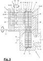
- Figure 3 shows a variant of the filter device (1) and the cleaning device (2), which largely with the first embodiment of Figure 1 and 2nd to match. There are differences in the design of the filter (6) and the spatial separation of the cleaning area (21) from one or more filter chambers (11). At least one filter chamber (11) is fluidically connected to the cleaning area (21) via a return channel (22) Transfer of the fluid pressure (P) connected.
- the disc filter (6) in this embodiment also has one of e.g. two parallel perforated support disks formed filter carrier (16) with at least one filter element (17) arranged between them.
- the hole arrangement on the support disks and the filter element (17) can be annular and concentric to the axis (15).
- the filter (6) can be segmented, the support disks having a plurality of perforated regions which are uniformly distributed around the axis (15) and are separated from one another by solid wall sections.
- the filter element (17) can accordingly be subdivided into a plurality of segments which are adapted to the hole regions and are correspondingly distributed.
- the filter device (1) can have a plurality of filter chambers (11) arranged concentrically around the axis (15) and a cleaning area (21) which is spaced apart from it and connected via at least one return channel (22).
- the detaching device (18) of the cleaning device (2) is again designed as a backwashing device (19) and is arranged in a stationary manner. It also has said collecting area (23) on the contamination side, which here is divided into a larger number of collecting channels (24) than in the first exemplary embodiment.
- the number of feed and discharge lines (26, 27) of the discharge device (3) has been changed and adapted accordingly. The same applies to the number and arrangement of the receiving pockets (36) and the actuators (33) on the rotating body (28). The function is otherwise the same as in the first embodiment.
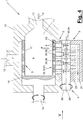
- FIG 4 and 5 show a further variant of the filter device (1) and the cleaning device (2), in which a filter (5) is used in the form of a tubular filter.
- the unfiltered fluid (7) flows through it from the outside from an annular chamber, the filter residues (9) being emitted radially outward in the cleaning area (21).
- the tubular filter (5) which is in turn rotatably mounted about an axis (15), has a filter carrier (16) in the form of a cylinder open on one end with a perforated jacket and a support and pin arrangement on the other end.
- the filter element (17) is e.g. arranged on the inside of the perforated cylinder (16) and has an annular shape. For example, be formed as a ring cartridge from a perforated screen belt.
- the collecting area (23) is again divided into several collecting channels (24) which, in contrast to the axial alignment of the first two variants, have a radial alignment here.
- Figure 4 and 5 also show the possibility of merging the collecting channels (24) and the feed lines (26), the discharge device (3) being correspondingly integrated into the housing (10) of the filter device (1).
- the discharge device (3) and the metering device (4) are otherwise of the same basic design as in the aforementioned exemplary embodiments, where the alignment and arrangement on the filter housing (10) is changed with a corresponding filter shape.
- the axes (15, 29) are aligned parallel to one another. In the first two embodiments, they have a crossed arrangement.
- the metering device (4) can be designed to be controllable. There are various possibilities. On the one hand, the rotational movement and rotational speed of the metering element (28) or of the rotating body can be controlled by means of the rotary drive (38). On the other hand, the size of the receiving pocket (35) can be controlled, e.g. via the ram stroke. The control can take place in coordination with the filter rotation. In a further development, a control can also be present in connection with a corresponding sensor system.
- Figures 9 and 10 illustrate a variant of a metering device (4), in which the actuator (33) has an adjusting device (39) for changing the tappet stroke.
- the adjusting device (39) has an axially movable adjusting element (40), which is designed, for example, as an adjusting rod and which extends longitudinally and preferably in alignment with the axis of rotation (29). It can be moved back and forth in the axial direction in a controlled manner by a drive, not shown.
- the one or more plungers (34) have an associated actuating element (41), which e.g. is designed as an adjusting opening, which surrounds the adjusting rod (40) at least in regions with an oversize corresponding to the tappet stroke.
- the adjusting elements (40, 41) can have a circular cross section.
- the adjusting opening (41) can also be designed as an elongated hole and the adjusting rod (40) in the opening area as a flat bar.
- the actuating elements (40, 41) have coordinated and interacting actuating surfaces (42, 43) which determine the ram stroke depending on the axial position of the actuating rod (40).
- the shelves (42, 43) are designed, for example, as a wedge surface limited on the circumference or as a circumferential cone.
- the sloping shelves (42, 43) can only be in places in the axial direction in the ram area be present and have a mutually adapted inclination against the axis of rotation (29).
- the actuating element (40) can optionally axially penetrate a plurality of plungers (34) and can have a plurality of positioning surfaces (42) in accordance with the number of plungers.
- Figure 10 illustrates the mode of action in an enlarged view.
- starting position is shown in dashed lines.
- the plungers (34) to form the respective receiving pocket (36) can at most approach the axis of rotation (29) and thus have a maximum stroke.
- the adjusting opening (41) has an opening width that is dimensioned in relation to the adjusting rod (40) in accordance with the desired tappet stroke.
- the opposite end faces of the plunger (34) are flush with the mouth opening (32).
- the receiving channel (37) can be designed as a blind channel open on one side, the actuator (33) having a drive means acting on the plunger (34), which, depending on the rotational position of the rotating body (28), around the Axis (29) and according to the arrangement of the lines (26,27) is controlled.
- the feed and discharge lines (26, 27) can have a non-aligned alignment in this variant.
- several such lines (26, 27) can be distributed on The circumference of the rotating body (28) and the actuator (33) can be arranged.
- the drive means generates a pressure force in a controlled manner and pushes out the plunger (34) together with the portion of material (35).
- the fluid pressure (P) can push back the plunger (34) and form the receiving pocket (36).
- the actuator (33) or the drive means can replace the plunger and form the pocket bottom itself.
- Figure 31 to 33 and 36, 37 show constructive designs for this
- the receiving pocket (36) can be replaced by a flexible hollow body, e.g. a bubble is formed which replaces the plunger and which is acted upon by a drive means for changing the volume and e.g. is contracted or compressed.
- a drive means for changing the volume and e.g. is contracted or compressed e.g. is contracted or compressed.
- the material portion (35) contained can be expelled.
- the design and mode of operation can be similar to that of inkjet printers.
- a drive means can be designed and controlled in any suitable manner.
- a fluidic drive means with power transmission through a compressed gas or through a liquid can be formed, which pushes out the plunger (34), which acts as a piston, by a limited distance when the force is applied.
- the plunger (34) it is possible to design the plunger (34) as a flexible bladder which is arranged in the receiving channel (37) and which is filled as required with a fluid pressure medium, whereby it expands while reducing the pocket volume.
- the supply lines for a fluid pressure medium leading to the various actuators (33) or drive means can be laid in the rotating body (28).
- a plurality of receiving pockets (36) and a plurality of plungers (34), bubbles or the like acted upon by the same or different drive means can be present on a circumferential line of the rotating body (28) be.
- a drive means can be used as an electromagnetic expansion means, e.g. be designed as a piezo element. It can act on a thin piston-like plunger (34) or form the pocket bottom itself. It can be controlled electrically by a corresponding control system via a corresponding line routing in the rotating body (28).
- a cleaning device (2) can have a detaching device (19) which is designed as a mechanical separating device (20).
- the separating device (20) can have the shape of a scraper or lifter, for example.
- Figure 16 to 26 and 29 to 38 show by way of example such scrapers or lifters not covered by claim 1.
- the discharge device has, for example, a rotatable screw shaft which is arranged in the feed line (26), a metering device (4) of the type described above being arranged at the end thereof.
- the worm shaft can also be dispensed with, the filter residues lifted off the scraper being conveyed from the filter space to the metering device (4) by the fluid pressure.
- a rotating worm shaft or other separating means can also be present, which mechanically lifts the filter residues (9) from the filter element (17) and leads them to a feed line (26).
- a worm shaft can, for example, according to Figure 27 and 28 be trained.
- the filter element (27) can also be of any design and can in particular have a disk or tube shape.
- a metering device (4) of the type described above, in particular with an adjusting device (39) or An alternative embodiment of the actuator (s) (33) can also be arranged directly on a filter (5, 6). It can be arranged in the wall of the filter housing (11) and can also protrude with its rotating body into the filter chamber (11) or the cleaning area (21). A feed line (26) can be dispensed with, so that the filter residues (9), which may have been lifted and pent up by a mechanical separating device (20) not covered by claim 1, are conveyed directly into the receiving pockets (36) of the rotating body (28).
- the metering device (4) can preferably have actuators (33) with an angular offset and, if appropriate, with the drive means described above.
- the detached filter residues can also be discharged in the stream, the metering device (4) and the metering element (28) being designed differently, for example according to Figure 11, 12 or 25, 26 .
- the transport of the detached filter residues can be driven by the fluid pressure (P).
- Figures 11 and 12 show in longitudinal and cross section a further modification of a filter device (1) with a filter (5), a cleaning device (2) and a discharge device (3) with a metering device (4).
- the discharge and metering device (3, 4) can be arranged several times and distributed on the filter (5).
- the cleaning device (2) and the discharge device (3) with the metering device (4) can be an integral part of the filter device (1). Alternatively, they can be stand-alone and attachable devices that can also be retrofitted if necessary.
- the design also applies to the other variants described below.
- the filter (5) is in the embodiment of Figures 11 and 12 designed as a tubular filter.
- the fluid flows radially through it from the outside in an annular chamber.
- the Filter (5) can be rotatably mounted about an axis (15) and can rotate about this axis (15) during the filtering process and the passage of fluid.
- the axis (15) can have a controllable rotary drive (not shown).
- the rotation and filtering can be done continuously.
- the speed of rotation can be adapted to different fluids and to different operating requirements, for example varying amounts of fluid, pressures, temperatures, solids loads etc.
- the tubular filter (5) has a filter support (16) in the form of a cylinder open on one end face with a perforated jacket and a support and pin arrangement on the other end face.
- the filter element (17) is e.g. arranged on the inside of the perforated cylinder (16) and has an annular shape. For example, be formed as a ring cartridge from a perforated screen belt.
- the cleaning device (2) serves to detach the aforementioned filter residues and has a detachment device (18), which in the exemplary embodiment of Figure 11 is designed as a backwashing device (19).
- the filter residues are removed with the fluid pressure (P) acting on the clean side of the filter (5).
- the cleaning device (2) can act continuously, alternatively discontinuously or intermittently, during the filtering process. It is assigned to the filter chamber (11) or the process space and has a cleaning area (21) through which the rotating filter (5) is moved, for example, permanently.
- the collecting area (23) can be located within the filter chamber (11) and can be sealed off in a suitable manner. The seal prevents the detached filter residue from escaping into the area of the fluid to be filtered.
- the collecting area (23) is tightly connected on one side to the filter (5), in particular the perforated filter support (16) facing it. On the other outflow side, the collecting space (23) connects to the discharge device (3).
- the collecting area (23) can be a one-piece space surrounded by the seal.
- the collecting area (23) is divided into a plurality of parallel collecting channels (24). Their distribution can match the hole distribution on the jacket of the filter carrier (16).
- the cleaning device (2) and the collecting area (23) are arranged stationary in the exemplary embodiment shown. During the filter rotation, the jacket holes and the collecting channels (24) always come to coincide, so that a flow through the detached filter residues (9) is possible.
- the discharge device (3) is arranged in the direct connection to the cleaning device (2) and has one or more feed lines (26) which are arranged and aligned in accordance with the collecting area (23) or the collecting channels (24) and to these for one Connect the flow connection in alignment.
- the discharge device (3) can be arranged locally separated and at a distance from the cleaning device (2) and the filter device (1), with a bridging or extension line for connection with the collection area (23) or the collection channels (24).
- the discharge device (3) is in the embodiment shown in FIG Figures 11 and 12 and arranged stationary in the aforementioned variant and mounted, for example, on the filter housing (1).
- the discharge device (3) has a metering device (4) with a movable metering element (28) following the one or more supply lines (26).
- the metering device (4) can shut off the feed line (s) (26) in the outflow direction and prevent undesired leakage of filter residues.
- the metering device (4) is designed in such a way that it picks up the detached filter residues either in current or in portions from the feed line (s) (26) and releases them again at another, spatially separate location.
- one or more discharge lines (27) are arranged in the housing (25), which take up the material flow or the material portions of the filter residues, if necessary bring them together in a collecting channel and then lead them out of the discharge device (3).
- the single or multiple supply and discharge lines (26, 27) can be present in a corresponding number and arrangement.
- the dosing device (4) is arranged between the feed line (s) (26) and the discharge line (s) (27) in the housing (25).
- the metering device (4) can be controlled.
- the metering device (4) has a metering element (28) which is displaceable along a central axis (29) and preferably also parallel to the filter axis (15) and which is designed, for example, as a cylindrical plunger or as a shaft. Alternatively, the metering element (28) can have a flattened bar shape.
- the metering device (4) can be a controllable drive (44), in particular a Sliding drive, for the metering element (28), which is symbolized by an arrow. Additionally or alternatively, a likewise symbolized rotary drive (38) can be present. In a further modification, motor drives (38, 44) can be dispensed with and the metering element (28) can be adjusted manually.
- the controllable drive (44) can also be a controllable actuator (33) according to the exemplary embodiments of Figures 9 and 10 form.
- the metering of the material discharge is controlled via the sliding position and / or the rotary position of the metering element (28).
- the drive (s) (44, 38) can be matched to the rotary drive or the possibly changing rotational speed of the filter (5).
- the metering element (28) has one or more receiving pockets (36) on its body, which in this variant are designed as transverse channels (45) penetrating the body and open at the ends. Their number, size and arrangement can depend on the number, size and arrangement of the feed lines (26) and, if applicable, discharge lines (27).
- the lines (26, 27) and the transverse channels (45) preferably have the same orientation.
- the transverse channels (45) axially spaced apart are separated by solid areas (47) of the dosing element (28).
- the metering element (28) is otherwise tightly surrounded by the wall (30) of the housing (25) with the exception of the connection points of the feed line (s) (26) and discharge line (s) (27). It can block, meter, throttle or release the direct flow between the supply and discharge line (s) (26, 27). In the blocked position, it prevents external environmental influences from passing through the discharge line (s) (27) into the collecting area (23) and further into the filter chamber (11).
- Figure 13a - d show the dosing device (4) in different operating positions.
- Figure 13a corresponds to the representation of Figure 11 and shows the complete filter device (1). In the operational and open position of Figure 13a connect all cross channels (45) in alignment with the feed and discharge lines (26, 27) and allow the maximum flow of a material flow.
- transverse channels (45) are offset laterally at a distance from the supply and discharge lines (26, 27), the openings of which are closed by the solid areas (47).
- Figure 13d shows a further metering option with an extended metering element (28). This is shifted so far to the side that only one transverse channel (45) is coupled to a feed and discharge line (26, 27). The other supply and discharge lines (26, 27) are closed by the extended solid area (47). Depending on the sliding position, the number of cross channels (45) involved in the material discharge can thus be changed.
- the shaft-like metering element (28) can be rotated about the axis (29). This also enables the flow connection of the transverse channels (45) to the supply and discharge lines (26, 27) can be influenced.
- Figure 12 shows the aligned flow position. With a rotation through 90 °, for example, a blocking position through the solid area (47) and with a further rotation through 90 ° a flow position is reached again.
- the metering element (28) can continuously and intermittently release and meter the flow of the detached filter residues in the manner described above. Portioning is also possible. If the receiving pocket (36) or the transverse channel (45), which is open at both ends, is moved into a blocking position and / or rotated in the filled state, the material portion contained is enclosed and the next time a passage or flow position is taken up by the material pressure (P) and ejected the subsequent residue material. At the same time, the receiving pocket (36) or the transverse channel (45) is refilled and can then be closed by a renewed sliding or rotating movement. In this way, a timed and portioned material discharge can take place.
- Figures 14 and 15 show a first modification of a discharge device (3) and dosing device (4) of Figures 11 and 12 .
- the filter device (1) and the cleaning device (2) can have the same design as in Figures 11 and 12 to have.
- the discharge device (3) in turn has one or more feed lines (26) adjoining the collecting area (23).
- the metering device (4) has a metering element (28) designed as a shaft, which can rotate about a central axis (29) by means of a rotary drive (38). If necessary, it can also be moved axially with a slide drive, not shown.
- the metering element (28) has a plurality of receiving pockets (36), each of which is formed by a shortened transverse channel (45) which opens on the one hand on the shaft jacket and on the other hand on an axially common central channel (46).
- the transverse channels (45) are arranged offset to one another in the circumferential or rotational direction with respect to the axis (29). They can each be assigned to a feed line (26) with which they reach the flow position once per rotation.
- the supply line (26) is closed by the solid area (47) over the rest of the rotation path.
- the central channel (46) is connected to a discharge line (27) or can form it.
- a common central channel (46) several individual parallel and internal axial channels can be present.
- FIGs 16 and 17 as well as the associated detailed representations of Figure 18 to 20 show a second modification of the filter device (1), the cleaning device (2) and the discharge device (3) together with the metering device (4). This causes material to be discharged in portions.
- the filter (5) is again designed as a rotating tubular filter of the type described in the introduction and flows through from outside to inside, the filter residues being deposited on its outer filter surface (52).
- the cleaning device (2) has a detachment device (18) for the filter residues, which, in a modification of the above-mentioned exemplary embodiments, is designed as a mechanical separating device (20) not covered by claim 1.
- the separating device (20) has a scraper (53) positioned transversely or radially or obliquely against the filter surface (52) and against the filter rotation direction symbolized by an arrow, which scraper removes the filter residues.
- the scraper (53) is in this variant as a scraper bar mounted in the housing (10) with a solid scraper edge (55) is formed on a bar edge, which is relatively steep and almost radial against the rotating filter surface (52).
- the collecting area (23) is formed in front of the scraper (53) in the separating device (20).
- the metering device (4) is integrated in the housing (10) of the filter device (1) and projects into the ring area of the filter chamber (11), which surrounds the outside of the filter (5).
- the metering device (4) in turn has a movable metering element (28), which is designed here as a rotating shaft and is provided with a rotary drive (38).
- the dosing element protrudes into said ring area and is directly connected to the collecting area (23).
- the discharge device (3) has only one discharge line (27).
- the metering element (28) extending along the filter jacket has one or more peripheral receiving pockets (36) on the shaft jacket, which are clocked according to the rotational movement and filled with filter residues from the collection area (23) and emptied on the discharge line (27).
- the receiving pocket (s) (36) is / are e.g. formed as an axial groove-like recess or depression on the shaft jacket.
- the metering element (28) is surrounded on one side in areas densely by the scraper bar.
- the dynamic pressure in the collecting area (23) can be influenced by a coordinated shape and arrangement of the metering element (28) and the scraper (53).
- the rotating metering element (28) takes accordingly Figure 16 and 18th in its groove (36) the filter residues detached from the scraper edge (55) and located in the collecting area (23) in front of them and transported by further rotation in the direction of the arrow to a discharge line (27) which is peripheral to the metering element (28) connects and extends parallel to this along the axis (15, 29).
- Figure 17 , 19th and 21 show the delivery position in which the filter residues fall from the receiving pocket (36) into the discharge line (27), which is preferably located directly underneath.
- the bag can be emptied according to Figure 17 and 20th are supported by a broaching element (48) which is arranged in the discharge line (27) and which is designed, for example, as an axially controlled displaceable plunger or scraper or as a screw conveyor.
- Figures 21 and 22 show a further modification of the discharge device (3) and metering device (4), the filter device (1) and the cleaning device (2) with the separating device (20) and the bar-shaped scraper (53) according to the previous exemplary embodiment of FIG Figures 16 and 17 are trained.
- the dosing element (28) is in the variant of Figures 21 and 22 designed as an axially displaceable plunger and moved by means of a controlled drive (44).
- a controlled drive 44
- This can have a circular shape in cross section. It can also be rotatably mounted and, if necessary, be provided with a rotary drive (38). It protrudes into the said ring area of the filter chamber (11) and can be mounted in the housing (10).
- the metering element (28) has a plurality of receiving pockets (36), which here are designed as ring-like depressions on the shaft jacket and are axially separated from one another by ring webs are.
- the dosing element (28) can have several, for example, two axially spaced apart pocket areas with a longer solid area (47) arranged between them. Wider solid areas (47) can also be arranged at the shaft ends.
- the pocket areas and the central solid area (47) of the metering element (28) are alternately brought into connection with the collecting area (23) by means of a reversing sliding movement.
- the detached filter residues are taken up in the ring-like receiving pockets (36).
- the receiving pockets (36) are open towards the collecting area (23) and are otherwise tightly enclosed by the wall of the housing (10) and the scraper (53) not covered by claim 1.
- the dosing element (28) is then axially displaced, as a result of which the filled receiving pockets (36) are transported into a delivery area (not shown) or to a discharge line (27), where they are moved by gravity or with the possible support of a clearing element or by flushing or Like. be emptied. In the meantime, either the central solid area (47) or the other pocket area can be located on the collecting area (23). With this variant of a dosing device (4), a portion-wise discharge of material is also provided.
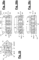
- FIG 25 to 26c show a further variant of a discharge device (3) together with a metering device (4), which here has a mechanical separating device (20), for example a scraper (53) according to the previous exemplary embodiments of FIG Figure 16 to 24 , is combined.
- the filter device (1) is otherwise the same as in the previous exemplary embodiments.
- the dosing element (28) is similar to the first embodiment of FIG Figures 11 and 12 designed as a displaceable shaft or plunger with a sliding drive (44). It has one or more receiving pockets (36) in the form of transverse channels (45) passing through the shaft body, which can have the same or different angular orientation and which correspond in number, size and orientation with subsequent feed and discharge lines (26, 27).
- the metering element (28) can be shifted axially according to different operating positions Figure 26a-c take in.
- FIG 26a the flow or open position is shown.
- Figure 26b a throttle position with only partial coverage of transverse channels (45) and feed and discharge lines (26, 27) and a correspondingly reduced flow rate is shown.
- Figure 26c shows the blocking position, in which the supply and discharge lines (26) are closed and blocked off by solid areas (47).
- the metering element (28) can additionally or alternatively perform a rotary movement and have a corresponding rotary drive (38) for this.
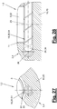
- Figure 27 and 28 show a further modification of the cleaning device (2) and the discharge device (3) and the metering device (4).
- the detaching device (18) is in turn designed as a mechanical separating device (20) which is not covered by claim 1, and is designed constructively as a screw conveyor (54).
- This is mounted in the housing (10) and extends, for example, in the axial direction on and along the filter surface (52) of the rotating tubular filter (5).
- the screw conveyor (54) lifts the filter residues from the filter surface (52) during a rotation and transports them to an axially adjoining feed line (26) in the housing (10), which is connected to a metering element (28) of the type described above.
- This can be, for example, a shaft or a tappet with one or more peripheral receiving pockets (36) according to one of the previously described exemplary embodiments of Figure 11 to 26 be.
- the screw conveyor (54) is provided with a controlled drive, which is switched on and off as required.
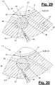
- FIGS 29 and 30 A further modification of the discharge and metering device (3, 4) and the cleaning device (2) is shown.
- a scraper (53) with a blade (56) being used.
- the blade (56) is inclined and set against the filter rotation direction symbolized by an arrow on the filter surface (52).
- the thin blade (56) for example, can have a blade holder (57) indicated by dashed lines.
- the blade holder (57) arranged in the housing (10) can be moved and set against the filter (5) with an adjusting means (58), also symbolized by a broken line, for example with adjusting screws and possibly with spring support.
- the metering element (28) is designed as a rotatable cylindrical shaft and is provided with a rotary drive (38), the shaft having one or more peripheral receiving pockets (36) which are designed as trough-shaped or channel-shaped depressions on the shaft jacket.
- the dosing element (28) in turn protrudes into said ring area and the collecting area (23). On another side, it is connected to a discharge line (27).
- the receiving pockets (36) are flatter in this exemplary embodiment than in the variants described above and have a greater extent in the circumferential direction.
- the pocket bottom is convex, preferably concentric to the axis of rotation (29).
- the clearing element (48) is designed here as a scraper with a spring-loaded blade which is inclined against the direction of rotation of the metering element (28) and against the curved pocket bottom.
- the scraper (48) is adjustable by means of an adjusting screw or the like.
- Figure 31 to 33 show a further variant of the discharge and metering device (3, 4) for a portionwise discharge of material.
- the cleaning device (2) can have any detachment device (18), in particular designed according to the previous variants, which is designed here, for example, as a mechanical separating device (20) with a scraper (53).
- the discharge device (3) has one or more feed lines (26) opening at the collecting area (23).
- the dosing element (28) is designed as an axially displaceable plunger, which has one or more receiving pockets (36) in the form of a penetrating transverse channel (45) which, in the flow position, connects flush and in alignment to a feed line (26).
- the plunger (28) is moved in the axial direction in a controlled manner by a sliding drive (44). The direction of movement can be oriented transversely to the filter axis (15).
- a plurality of receiving pockets (36) can be arranged in a row along the filter jacket and the filter axis (15).
- the metering device (4) also has a piston (34), which can be single or multiple and is aligned with a feed line (26).
- the piston (34) can pass through the transverse channel (45) and plunge into the feed line (26). It is moved in a controlled manner in the axial direction by a sliding drive (44).
- Figure 31 shows a blocking position of the metering device (4), in which the piston (34) is extended and the aligned arrangement of transverse channel (45) and feed line (26) passes through, the front piston end to the edge of the filter chamber (11) or to the latter Ring area protrudes and ends flush with the housing wall (10).
- this blocking position collected filter material is collected in the collecting area (23) in front of the scraper (53) which, for example, is equipped with a blade (56) and does not fall under claim 1.
- Figure 33 shows the delivery position in which the dosing element (28) with the filled receiving pocket (36) is shifted to the side, the solid area (47) closing the feed line (26).
- the receiving pocket (36) is brought into a delivery area, which may be outside the housing (10) and in which a pocket can be emptied by gravity or a clearing element or in another suitable manner.
- the metering element (28) is then returned to the starting position Figure 31 retracted and the piston (34) advanced, whereby the portioned dosing process can begin again.
- the piston (34) can be omitted, the housing (10, 25) closing the receiving pocket (36) downward.
- Figure 34 and 35 show another embodiment of a filter device (1), a cleaning device (2), a discharge device (3) and a metering device (4).
- the filter (5) rotating about an axis (15) in the filter chamber (11) is acted upon permanently or intermittently on its filter surface (52) by a mechanical separating device (20) not covered by claim 1.
- the separating device (20) is designed in this case as a movable scraper (53) which is provided with a blade holder (57) with one or more, for example two, V-shaped blades (56).
- the blade holder (57) is connected to an adjusting means (58) which, with a suitable drive, effects a scraper and blade movement along the filter surface (52).
- the adjusting means (58) can be designed, for example, as a slide which generates a movement parallel to the axis (15) of the tubular filter (5).
- the blades (56) are placed against the filter surface (52) and are moved along it, detaching the filter residues and transporting them to an axially connecting feed line (26) and to a metering element (28) there according to one of the previously described Pass examples.
- the different blade inclinations are favorable for the scraping and conveying process in the respective direction of movement.
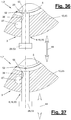
- FIG. 36 and 37 A combination of a detachment device (18), in particular a mechanical separation device (20) not covered by claim 1, with a metering device (4) and a discharge device (3) is shown.
- the metering device (4) has a metering element (28) which is designed as an axially displaceable plunger and at the same time as a scraper (53). It is used for a portion of material discharge.
- the metering device (4) and the mechanical separating device (20) form a structural and functional unit.
- the dosing element (28) is aligned with a predominantly radial directional component to the filter axis (15) and is mounted in the housing (10).
- the front of the dosing element (28) can be moved into the said ring area of the filter chamber (11) and to the filter surface (52).
- the dosing element (28) has one or more lateral receiving pocket (s) (36), which can be designed as a trough-like or groove-like depression.
- a scraping edge (55) is arranged or designed to remove the filter residues.
- the dosing element (28) is guided in a housing opening and is acted upon by a sliding drive (44).
- the receiving pocket (36) can have such a large axial length that it extends a little into the housing opening in the extended plunger position.
- the receiving pocket (36) is thus open on the one hand to the collecting area (23) for entry of the detached filter residues and on the other hand has a part of the housing wall covered area.
- Figure 36 shows this training.
- a discharge line (27) is arranged in the housing wall, into which pockets can be emptied.
- the discharge line (27) arranged on the side of the tappet can have a circular channel shape and extend along the axis (15).
- the shape of the pocket bottom can correspond to the cross-sectional shape of the line (27) and this e.g. add a circular cross-sectional shape in the emptying position.
- the emptying can be supported by a clearing element (not shown).
- the shape and orientation of the metering element (4) can be based on the respective filter geometry.
- a tubular filter (5) is used.
- a disc filter or a filter (5) with a different filter geometry is possible.
- the dosing element (28) can extend along the filter axis (15) and have a length at least corresponding to the filter length. This is particularly the case with the variants in which the metering element (28) extends into the filter chamber (11) or into the ring area.
- the plunger (28) can have a strip or plate shape.
- the piston (34) can also have an elongated strip or plate shape.
- Figure 38 shows a variant of the discharge device (3) and the metering device (4), in which the metering device (4) has a metering element (28) with a solidification device (49).
- the filter device (1) and the cleaning device (2) together with the detachment device (18) can be designed in any manner and in particular according to one of the previous variants.
- a mechanical separating device (20) with a scraper (53) is not used.
- the discharge device (3) has one or more feed lines (26) opening at the collecting area (23), which at the other end are permanently connected to a channel-like receiving pocket (36) in the metering element (28).
- the single or multiple existing receiving pocket (36) can have a constriction at its rear end.
- At least one discharge line (27) can follow behind it.
- the metering element (28) has a body which can be mounted on the housing (10, 25) and which accommodates the receiving pocket (s) (36) and parts of the strengthening device (49).
- the solidification device (49) influences the flowability, in particular the state of aggregation, the detached filter residues and the fluid particles contained therein, in particular plastic particles.
- This mass or mixture can e.g. solidified or liquefied. Accordingly, this mass may or may not pass through the receiving pocket (s) (36) and, in particular, at the narrowing thereof.
- a solidified mass forms a plug that blocks the receiving pocket (36) and prevents material discharge.
- the flow behavior in particular solidification and liquefaction, can be changed in different ways. In the preferred embodiment shown and this is done thermally.
- a solidification occurs through the supply of cold and a liquefaction through supply of heat.
- the hardening device (49) has a suitable cooling device (50) and a heating device (51).
- the cooling and heating device (50, 51) can have external cooling or heating units and lines connected there for a medium that transfers heat or cold, which extend as far as the metering element (28) and in the vicinity of the receiving pocket (s) (36) are led.
- the cooling and heating lines can be arranged one behind the other in the order mentioned in the discharge direction.
- the cooling and / or heating device (50, 51) can be completely attached to the metering element (28) and can be supplied with operating means, in particular electricity and water, from the outside.
- the solidification and liquefaction can be carried out by other measures, e.g. by chemical reaction with the addition of a reactor or catalyst or by applying electrical or electromagnetic fields.
- the solidification device (49) can also bring about a flow stop of the mass by magnetic force under the action of magnetically conductive mass constituents.
- the discharge device (3) can connect directly to a collection area (23) without a feed line (26). They can also be arranged on or on the filter housing (10).
- the discharge devices (3) shown here can also be connected to a collecting area (23) via a feed line (26). This can, for example, according to one of the embodiments according to Figure 1 to 15 respectively.
- the metering device (4) for the discharge of a movable mass (9), in particular of detached filter residues, from a pressurized process space also has independent inventive significance and can also be used with any other cleaning and discharge devices (2, 3).
- the metering device (4) has an axially displaceable or rotating about an axis (29) metering element (28), in particular a shaft, with one or more, arranged on the outside of the metering element (28) and its volume by means of an actuator (33 ) with a tappet (34) changeable receiving pocket (s) (36) for receiving and dispensing a portion (35) of the mass (9), the actuator (33) having an adjusting device (39) for changing the tappet stroke.
- the other constructive and functional details can be according to Figures 9 and 10 be trained.
- the direction of flow of the fluids through the filters (5, 6) can be reversed.
- the flow direction can be directed from the inside to the outside.
- the filter (5, 6) can be arranged stationary, the cleaning device (2) and possibly also the discharge device (3) and the metering device (2) rotating about an axis (15).
- the filter can have any shape and design. Instead of the tube filter (5) shown, a disc filter or another filter can be used. A disc filter or other filter is also used preferably moved, in particular rotated about an axis (15). With the other filter geometry, the assignment and alignment of the components of the cleaning device (2), the discharge device (3) and the metering device (4) change accordingly. In particular, the components of the detachment device (18) have a correspondingly changed orientation and arrangement.
- a driven clearing element (48) and / or the screw conveyor (54) can have a controllable and, if necessary, adjustable drive. This drive can be controlled or regulated independently of a rotary drive of the filter (5).
Landscapes
- Engineering & Computer Science (AREA)
- Mechanical Engineering (AREA)
- Chemical & Material Sciences (AREA)
- Chemical Kinetics & Catalysis (AREA)
- Extrusion Moulding Of Plastics Or The Like (AREA)
- Coating Apparatus (AREA)
- Filtration Of Liquid (AREA)
- Filtering Of Dispersed Particles In Gases (AREA)
Priority Applications (1)
| Application Number | Priority Date | Filing Date | Title |
|---|---|---|---|
| PL14741209T PL3010620T3 (pl) | 2013-06-18 | 2014-06-18 | Urządzenie filtracyjne i sposób odprowadzania |
Applications Claiming Priority (3)
| Application Number | Priority Date | Filing Date | Title |
|---|---|---|---|
| DE201320102619 DE202013102619U1 (de) | 2013-06-18 | 2013-06-18 | Austragvorrichtung |
| DE202013103371.5U DE202013103371U1 (de) | 2013-07-25 | 2013-07-25 | Austragvorrichtung |
| PCT/EP2014/062877 WO2014202690A1 (de) | 2013-06-18 | 2014-06-18 | Austragvorrichtung und austragverfahren |
Publications (2)
| Publication Number | Publication Date |
|---|---|
| EP3010620A1 EP3010620A1 (de) | 2016-04-27 |
| EP3010620B1 true EP3010620B1 (de) | 2020-04-29 |
Family
ID=51211178
Family Applications (1)
| Application Number | Title | Priority Date | Filing Date |
|---|---|---|---|
| EP14741209.2A Active EP3010620B1 (de) | 2013-06-18 | 2014-06-18 | Filtereinrichtung und austragverfahren |
Country Status (7)
| Country | Link |
|---|---|
| US (1) | US10265649B2 (pl) |
| EP (1) | EP3010620B1 (pl) |
| KR (1) | KR102092190B1 (pl) |
| CN (1) | CN105473204B (pl) |
| ES (1) | ES2799436T3 (pl) |
| PL (1) | PL3010620T3 (pl) |
| WO (1) | WO2014202690A1 (pl) |
Families Citing this family (8)
| Publication number | Priority date | Publication date | Assignee | Title |
|---|---|---|---|---|
| DE202016103608U1 (de) * | 2016-07-06 | 2016-08-22 | Nordson Corporation | Filtervorrichtung und Reinigungseinrichtung zum Entfernen von Schmutzpartikeln von einem Filterelement einer Filtervorrichtung Filtervorrichtung und Reinigungseinrichtung zum Entfernen von Schmutzpartikeln von einem Filterelement einer Filtervorrichtung |
| EP3308940B1 (de) * | 2016-10-17 | 2025-03-05 | Next Generation Analytics GmbH | Filtersystem für viskose oder hochviskose flüssigkeiten, insbesondere kunststoffschmelzen und verfahren zur filtration von viskosen oder hochviskosen flüssigkeiten |
| JP6828497B2 (ja) * | 2017-02-17 | 2021-02-10 | セイコーエプソン株式会社 | 液体吐出装置及びフィルターの洗浄方法 |
| US11260570B2 (en) * | 2018-05-07 | 2022-03-01 | PSI-Polymer Systems, Inc. | Filtration apparatuses and screen changer devices for polymer processing and related methods |
| CN110975382B (zh) * | 2019-12-02 | 2021-04-13 | 河海大学 | 一种液压控制的变精度叠片式过滤器及其运行工艺 |
| CN114699828B (zh) * | 2022-04-12 | 2023-12-22 | 重庆吉江环保产业集团有限公司 | 一种工业废水处理加工方法 |
| DE102023102233A1 (de) | 2023-01-31 | 2024-08-01 | Nordson Corporation | Filtervorrichtung zum Abscheiden von Verunreinigungen aus einer Polymerschmelze |
| DE102023111800A1 (de) | 2023-05-05 | 2024-11-07 | Nordson Corporation | Verfahren zum Steuern einer Filtervorrichtung, Verfahren zum Filtern einer eines hochviskosen Fluides und Filtervorrichtung |
Citations (1)
| Publication number | Priority date | Publication date | Assignee | Title |
|---|---|---|---|---|
| DE102007063240A1 (de) * | 2007-12-31 | 2009-07-02 | Mahle International Gmbh | Separationseinrichtung |
Family Cites Families (7)
| Publication number | Priority date | Publication date | Assignee | Title |
|---|---|---|---|---|
| NO156927C (no) * | 1981-08-04 | 1987-12-23 | Mueller Drm Ag | Framgangsmte for kontinuerlig fortykning av suspensjoner. |
| DE3422093C2 (de) * | 1984-06-14 | 1986-07-24 | Mannesmann AG, 4000 Düsseldorf | Entstaubungsvorrichtung |
| CN1006363B (zh) * | 1985-06-20 | 1990-01-10 | 曼内斯曼股份公司 | 除尘装置 |
| AT407611B (de) * | 1999-11-16 | 2001-05-25 | Econ Maschb Und Steuerungstech | Rückspülvorsatzgerät für eine filtereinrichtung |
| DE10229406A1 (de) | 2002-06-29 | 2004-01-22 | Ettlinger Kunststoffmaschinen Gmbh | Vorrichtung zum kontinuierlichen Filtern von Materialgemischen |
| CN101797793B (zh) * | 2009-02-11 | 2012-12-26 | 晶铁科技工业股份有限公司 | 塑料过滤装置 |
| DE102010055167A1 (de) * | 2010-12-18 | 2012-06-21 | Ettlinger Kunststoffmaschinen Gmbh | Vorrichtung zum kontinuierlichen Filtern von Materialgemischen |
-
2014
- 2014-06-18 WO PCT/EP2014/062877 patent/WO2014202690A1/de not_active Ceased
- 2014-06-18 CN CN201480045759.XA patent/CN105473204B/zh active Active
- 2014-06-18 US US14/899,790 patent/US10265649B2/en active Active
- 2014-06-18 PL PL14741209T patent/PL3010620T3/pl unknown
- 2014-06-18 KR KR1020167000710A patent/KR102092190B1/ko not_active Expired - Fee Related
- 2014-06-18 ES ES14741209T patent/ES2799436T3/es active Active
- 2014-06-18 EP EP14741209.2A patent/EP3010620B1/de active Active
Patent Citations (1)
| Publication number | Priority date | Publication date | Assignee | Title |
|---|---|---|---|---|
| DE102007063240A1 (de) * | 2007-12-31 | 2009-07-02 | Mahle International Gmbh | Separationseinrichtung |
Also Published As
| Publication number | Publication date |
|---|---|
| US10265649B2 (en) | 2019-04-23 |
| KR20160021818A (ko) | 2016-02-26 |
| US20160136546A1 (en) | 2016-05-19 |
| CN105473204A (zh) | 2016-04-06 |
| EP3010620A1 (de) | 2016-04-27 |
| CN105473204B (zh) | 2018-07-31 |
| KR102092190B1 (ko) | 2020-03-24 |
| PL3010620T3 (pl) | 2020-11-02 |
| ES2799436T3 (es) | 2020-12-17 |
| WO2014202690A1 (de) | 2014-12-24 |
Similar Documents
| Publication | Publication Date | Title |
|---|---|---|
| WO2014202690A1 (de) | Austragvorrichtung und austragverfahren | |
| DE69003460T2 (de) | Innenmischer. | |
| EP0061630B1 (de) | Spülbare Zahnradpumpe | |
| DE102012006563B3 (de) | Vorrichtung zum Filtrieren eines Fluids | |
| EP2061575B1 (de) | Vorrichtung zum kontinuierlichen filtern von verunreinigungen aus einer kunststoffschmelze | |
| DE2603663A1 (de) | Verfahren zur abgabe eines viskosen, fluessigen, insbesondere thermoplastischen materials und vorrichtung hierfuer sowie zur verfluessigung | |
| WO2014184132A1 (de) | Schmelzefilter mit einer antriebsvorrichtung für eine drehbare siebscheibe | |
| WO2020232487A1 (de) | Schmelzefilter | |
| EP1778379B1 (de) | Vorrichtung und verfahren zum filtrieren eines fluids, insbesondere für kunststoffverarbeitende anlagen | |
| EP4267368A1 (de) | Austragtechnik für kunststofffilter | |
| DE202013103371U1 (de) | Austragvorrichtung | |
| EP2907646B1 (de) | Grobpartikelabscheidevorrichtung | |
| EP2334874B1 (de) | Vorrichtung und verfahren zum aktivieren oder reinigen von brunnen | |
| DE69410066T2 (de) | Modulares Dosiergerät | |
| DE10312843B3 (de) | Vorrichtung zum Ausbringen von Ein- oder Mehrkomponentenmassen und Ventilanordnung hierfür | |
| DE3038623A1 (de) | Wachszylinder | |
| EP0564807A1 (de) | Vorrichtung zum Fördern oder Dosieren von viskosen Massen | |
| EP0148327B1 (de) | Kolbendosiervorrichtung einer Reaktionsgiessmaschine | |
| DE202013102619U1 (de) | Austragvorrichtung | |
| DE3834451C2 (pl) | ||
| AT16661U1 (de) | Filtereinrichtung | |
| DE102014102448B4 (de) | Vorrichtung und Verfahren zum Umformen, insbesondere Fließpressen, von metallischen Werkstücken | |
| DE19845702C2 (de) | Rühr- und Mischeinrichtung für einen Vorratsbehälter mit Dosiereinrichtung für zähflüssige Stoffe, wie Gießharz | |
| DE1241803B (de) | Absperrvorrichtung zum automatischen, periodischen Entschlammen von Filterkerzen durch Rueckspuelung | |
| DE102018209202A1 (de) | Fluidstromgenerator, Fördervorrichtung und Transportfahrzeug |
Legal Events
| Date | Code | Title | Description |
|---|---|---|---|
| PUAI | Public reference made under article 153(3) epc to a published international application that has entered the european phase |
Free format text: ORIGINAL CODE: 0009012 |
|
| 17P | Request for examination filed |
Effective date: 20160115 |
|
| AK | Designated contracting states |
Kind code of ref document: A1 Designated state(s): AL AT BE BG CH CY CZ DE DK EE ES FI FR GB GR HR HU IE IS IT LI LT LU LV MC MK MT NL NO PL PT RO RS SE SI SK SM TR |
|
| AX | Request for extension of the european patent |
Extension state: BA ME |
|
| DAX | Request for extension of the european patent (deleted) | ||
| STAA | Information on the status of an ep patent application or granted ep patent |
Free format text: STATUS: EXAMINATION IS IN PROGRESS |
|
| 17Q | First examination report despatched |
Effective date: 20180629 |
|
| REG | Reference to a national code |
Ref country code: DE Ref legal event code: R079 Ref document number: 502014014092 Country of ref document: DE Free format text: PREVIOUS MAIN CLASS: B01D0029940000 Ipc: B29C0048690000 |
|
| RIC1 | Information provided on ipc code assigned before grant |
Ipc: B01D 29/94 20060101ALI20191104BHEP Ipc: B29C 48/69 20190101AFI20191104BHEP |
|
| GRAP | Despatch of communication of intention to grant a patent |
Free format text: ORIGINAL CODE: EPIDOSNIGR1 |
|
| STAA | Information on the status of an ep patent application or granted ep patent |
Free format text: STATUS: GRANT OF PATENT IS INTENDED |
|
| INTG | Intention to grant announced |
Effective date: 20191213 |
|
| GRAS | Grant fee paid |
Free format text: ORIGINAL CODE: EPIDOSNIGR3 |
|
| GRAA | (expected) grant |
Free format text: ORIGINAL CODE: 0009210 |
|
| STAA | Information on the status of an ep patent application or granted ep patent |
Free format text: STATUS: THE PATENT HAS BEEN GRANTED |
|
| AK | Designated contracting states |
Kind code of ref document: B1 Designated state(s): AL AT BE BG CH CY CZ DE DK EE ES FI FR GB GR HR HU IE IS IT LI LT LU LV MC MK MT NL NO PL PT RO RS SE SI SK SM TR |
|
| REG | Reference to a national code |
Ref country code: GB Ref legal event code: FG4D Free format text: NOT ENGLISH |
|
| REG | Reference to a national code |
Ref country code: CH Ref legal event code: EP |
|
| REG | Reference to a national code |
Ref country code: DE Ref legal event code: R096 Ref document number: 502014014092 Country of ref document: DE |
|
| REG | Reference to a national code |
Ref country code: AT Ref legal event code: REF Ref document number: 1262627 Country of ref document: AT Kind code of ref document: T Effective date: 20200515 |
|
| REG | Reference to a national code |
Ref country code: IE Ref legal event code: FG4D Free format text: LANGUAGE OF EP DOCUMENT: GERMAN |
|
| REG | Reference to a national code |
Ref country code: NL Ref legal event code: FP |
|
| REG | Reference to a national code |
Ref country code: LT Ref legal event code: MG4D |
|
| PG25 | Lapsed in a contracting state [announced via postgrant information from national office to epo] |
Ref country code: SE Free format text: LAPSE BECAUSE OF FAILURE TO SUBMIT A TRANSLATION OF THE DESCRIPTION OR TO PAY THE FEE WITHIN THE PRESCRIBED TIME-LIMIT Effective date: 20200429 Ref country code: NO Free format text: LAPSE BECAUSE OF FAILURE TO SUBMIT A TRANSLATION OF THE DESCRIPTION OR TO PAY THE FEE WITHIN THE PRESCRIBED TIME-LIMIT Effective date: 20200729 Ref country code: FI Free format text: LAPSE BECAUSE OF FAILURE TO SUBMIT A TRANSLATION OF THE DESCRIPTION OR TO PAY THE FEE WITHIN THE PRESCRIBED TIME-LIMIT Effective date: 20200429 Ref country code: IS Free format text: LAPSE BECAUSE OF FAILURE TO SUBMIT A TRANSLATION OF THE DESCRIPTION OR TO PAY THE FEE WITHIN THE PRESCRIBED TIME-LIMIT Effective date: 20200829 Ref country code: PT Free format text: LAPSE BECAUSE OF FAILURE TO SUBMIT A TRANSLATION OF THE DESCRIPTION OR TO PAY THE FEE WITHIN THE PRESCRIBED TIME-LIMIT Effective date: 20200831 Ref country code: GR Free format text: LAPSE BECAUSE OF FAILURE TO SUBMIT A TRANSLATION OF THE DESCRIPTION OR TO PAY THE FEE WITHIN THE PRESCRIBED TIME-LIMIT Effective date: 20200730 Ref country code: LT Free format text: LAPSE BECAUSE OF FAILURE TO SUBMIT A TRANSLATION OF THE DESCRIPTION OR TO PAY THE FEE WITHIN THE PRESCRIBED TIME-LIMIT Effective date: 20200429 |
|
| PG25 | Lapsed in a contracting state [announced via postgrant information from national office to epo] |
Ref country code: LV Free format text: LAPSE BECAUSE OF FAILURE TO SUBMIT A TRANSLATION OF THE DESCRIPTION OR TO PAY THE FEE WITHIN THE PRESCRIBED TIME-LIMIT Effective date: 20200429 Ref country code: HR Free format text: LAPSE BECAUSE OF FAILURE TO SUBMIT A TRANSLATION OF THE DESCRIPTION OR TO PAY THE FEE WITHIN THE PRESCRIBED TIME-LIMIT Effective date: 20200429 Ref country code: RS Free format text: LAPSE BECAUSE OF FAILURE TO SUBMIT A TRANSLATION OF THE DESCRIPTION OR TO PAY THE FEE WITHIN THE PRESCRIBED TIME-LIMIT Effective date: 20200429 Ref country code: BG Free format text: LAPSE BECAUSE OF FAILURE TO SUBMIT A TRANSLATION OF THE DESCRIPTION OR TO PAY THE FEE WITHIN THE PRESCRIBED TIME-LIMIT Effective date: 20200729 |
|
| REG | Reference to a national code |
Ref country code: ES Ref legal event code: FG2A Ref document number: 2799436 Country of ref document: ES Kind code of ref document: T3 Effective date: 20201217 |
|
| PG25 | Lapsed in a contracting state [announced via postgrant information from national office to epo] |
Ref country code: AL Free format text: LAPSE BECAUSE OF FAILURE TO SUBMIT A TRANSLATION OF THE DESCRIPTION OR TO PAY THE FEE WITHIN THE PRESCRIBED TIME-LIMIT Effective date: 20200429 |
|
| PG25 | Lapsed in a contracting state [announced via postgrant information from national office to epo] |
Ref country code: RO Free format text: LAPSE BECAUSE OF FAILURE TO SUBMIT A TRANSLATION OF THE DESCRIPTION OR TO PAY THE FEE WITHIN THE PRESCRIBED TIME-LIMIT Effective date: 20200429 Ref country code: CZ Free format text: LAPSE BECAUSE OF FAILURE TO SUBMIT A TRANSLATION OF THE DESCRIPTION OR TO PAY THE FEE WITHIN THE PRESCRIBED TIME-LIMIT Effective date: 20200429 Ref country code: SM Free format text: LAPSE BECAUSE OF FAILURE TO SUBMIT A TRANSLATION OF THE DESCRIPTION OR TO PAY THE FEE WITHIN THE PRESCRIBED TIME-LIMIT Effective date: 20200429 Ref country code: DK Free format text: LAPSE BECAUSE OF FAILURE TO SUBMIT A TRANSLATION OF THE DESCRIPTION OR TO PAY THE FEE WITHIN THE PRESCRIBED TIME-LIMIT Effective date: 20200429 Ref country code: EE Free format text: LAPSE BECAUSE OF FAILURE TO SUBMIT A TRANSLATION OF THE DESCRIPTION OR TO PAY THE FEE WITHIN THE PRESCRIBED TIME-LIMIT Effective date: 20200429 Ref country code: MC Free format text: LAPSE BECAUSE OF FAILURE TO SUBMIT A TRANSLATION OF THE DESCRIPTION OR TO PAY THE FEE WITHIN THE PRESCRIBED TIME-LIMIT Effective date: 20200429 |
|
| REG | Reference to a national code |
Ref country code: CH Ref legal event code: PL |
|
| REG | Reference to a national code |
Ref country code: DE Ref legal event code: R097 Ref document number: 502014014092 Country of ref document: DE |
|
| PG25 | Lapsed in a contracting state [announced via postgrant information from national office to epo] |
Ref country code: SK Free format text: LAPSE BECAUSE OF FAILURE TO SUBMIT A TRANSLATION OF THE DESCRIPTION OR TO PAY THE FEE WITHIN THE PRESCRIBED TIME-LIMIT Effective date: 20200429 |
|
| PLBE | No opposition filed within time limit |
Free format text: ORIGINAL CODE: 0009261 |
|
| STAA | Information on the status of an ep patent application or granted ep patent |
Free format text: STATUS: NO OPPOSITION FILED WITHIN TIME LIMIT |
|
| PG25 | Lapsed in a contracting state [announced via postgrant information from national office to epo] |
Ref country code: LU Free format text: LAPSE BECAUSE OF NON-PAYMENT OF DUE FEES Effective date: 20200618 |
|
| 26N | No opposition filed |
Effective date: 20210201 |
|
| REG | Reference to a national code |
Ref country code: BE Ref legal event code: MM Effective date: 20200630 |
|
| PG25 | Lapsed in a contracting state [announced via postgrant information from national office to epo] |
Ref country code: IE Free format text: LAPSE BECAUSE OF NON-PAYMENT OF DUE FEES Effective date: 20200618 Ref country code: LI Free format text: LAPSE BECAUSE OF NON-PAYMENT OF DUE FEES Effective date: 20200630 Ref country code: CH Free format text: LAPSE BECAUSE OF NON-PAYMENT OF DUE FEES Effective date: 20200630 |
|
| PG25 | Lapsed in a contracting state [announced via postgrant information from national office to epo] |
Ref country code: BE Free format text: LAPSE BECAUSE OF NON-PAYMENT OF DUE FEES Effective date: 20200630 Ref country code: SI Free format text: LAPSE BECAUSE OF FAILURE TO SUBMIT A TRANSLATION OF THE DESCRIPTION OR TO PAY THE FEE WITHIN THE PRESCRIBED TIME-LIMIT Effective date: 20200429 |
|
| PG25 | Lapsed in a contracting state [announced via postgrant information from national office to epo] |
Ref country code: MT Free format text: LAPSE BECAUSE OF FAILURE TO SUBMIT A TRANSLATION OF THE DESCRIPTION OR TO PAY THE FEE WITHIN THE PRESCRIBED TIME-LIMIT Effective date: 20200429 Ref country code: CY Free format text: LAPSE BECAUSE OF FAILURE TO SUBMIT A TRANSLATION OF THE DESCRIPTION OR TO PAY THE FEE WITHIN THE PRESCRIBED TIME-LIMIT Effective date: 20200429 |
|
| PG25 | Lapsed in a contracting state [announced via postgrant information from national office to epo] |
Ref country code: MK Free format text: LAPSE BECAUSE OF FAILURE TO SUBMIT A TRANSLATION OF THE DESCRIPTION OR TO PAY THE FEE WITHIN THE PRESCRIBED TIME-LIMIT Effective date: 20200429 |
|
| PGFP | Annual fee paid to national office [announced via postgrant information from national office to epo] |
Ref country code: GB Payment date: 20240620 Year of fee payment: 11 |
|
| PGFP | Annual fee paid to national office [announced via postgrant information from national office to epo] |
Ref country code: DE Payment date: 20240617 Year of fee payment: 11 |
|
| PGFP | Annual fee paid to national office [announced via postgrant information from national office to epo] |
Ref country code: NL Payment date: 20240619 Year of fee payment: 11 |
|
| PGFP | Annual fee paid to national office [announced via postgrant information from national office to epo] |
Ref country code: AT Payment date: 20240617 Year of fee payment: 11 |
|
| PGFP | Annual fee paid to national office [announced via postgrant information from national office to epo] |
Ref country code: FR Payment date: 20240621 Year of fee payment: 11 |
|
| PGFP | Annual fee paid to national office [announced via postgrant information from national office to epo] |
Ref country code: PL Payment date: 20240515 Year of fee payment: 11 |
|
| PGFP | Annual fee paid to national office [announced via postgrant information from national office to epo] |
Ref country code: TR Payment date: 20240605 Year of fee payment: 11 |
|
| PGFP | Annual fee paid to national office [announced via postgrant information from national office to epo] |
Ref country code: IT Payment date: 20240628 Year of fee payment: 11 |
|
| PGFP | Annual fee paid to national office [announced via postgrant information from national office to epo] |
Ref country code: ES Payment date: 20240718 Year of fee payment: 11 |
|
| REG | Reference to a national code |
Ref country code: DE Ref legal event code: R119 Ref document number: 502014014092 Country of ref document: DE |
|
| REG | Reference to a national code |
Ref country code: NL Ref legal event code: MM Effective date: 20250701 |
|
| REG | Reference to a national code |
Ref country code: AT Ref legal event code: MM01 Ref document number: 1262627 Country of ref document: AT Kind code of ref document: T Effective date: 20250618 |
|
| GBPC | Gb: european patent ceased through non-payment of renewal fee |
Effective date: 20250618 |
|
| PG25 | Lapsed in a contracting state [announced via postgrant information from national office to epo] |
Ref country code: NL Free format text: LAPSE BECAUSE OF NON-PAYMENT OF DUE FEES Effective date: 20250701 |
|
| PG25 | Lapsed in a contracting state [announced via postgrant information from national office to epo] |
Ref country code: GB Free format text: LAPSE BECAUSE OF NON-PAYMENT OF DUE FEES Effective date: 20250618 |
|
| PG25 | Lapsed in a contracting state [announced via postgrant information from national office to epo] |
Ref country code: DE Free format text: LAPSE BECAUSE OF NON-PAYMENT OF DUE FEES Effective date: 20260101 |
|
| PG25 | Lapsed in a contracting state [announced via postgrant information from national office to epo] |
Ref country code: AT Free format text: LAPSE BECAUSE OF NON-PAYMENT OF DUE FEES Effective date: 20250618 |
|
| PG25 | Lapsed in a contracting state [announced via postgrant information from national office to epo] |
Ref country code: IT Free format text: LAPSE BECAUSE OF NON-PAYMENT OF DUE FEES Effective date: 20250618 |
|
| PG25 | Lapsed in a contracting state [announced via postgrant information from national office to epo] |
Ref country code: FR Free format text: LAPSE BECAUSE OF NON-PAYMENT OF DUE FEES Effective date: 20250630 |