EP3010309B1 - Electromagnetic heating - Google Patents
Electromagnetic heating Download PDFInfo
- Publication number
- EP3010309B1 EP3010309B1 EP15192062.6A EP15192062A EP3010309B1 EP 3010309 B1 EP3010309 B1 EP 3010309B1 EP 15192062 A EP15192062 A EP 15192062A EP 3010309 B1 EP3010309 B1 EP 3010309B1
- Authority
- EP
- European Patent Office
- Prior art keywords
- heating
- cavity
- feeds
- power
- energy
- Prior art date
- Legal status (The legal status is an assumption and is not a legal conclusion. Google has not performed a legal analysis and makes no representation as to the accuracy of the status listed.)
- Revoked
Links
Images


Classifications
-
- H—ELECTRICITY
- H05—ELECTRIC TECHNIQUES NOT OTHERWISE PROVIDED FOR
- H05B—ELECTRIC HEATING; ELECTRIC LIGHT SOURCES NOT OTHERWISE PROVIDED FOR; CIRCUIT ARRANGEMENTS FOR ELECTRIC LIGHT SOURCES, IN GENERAL
- H05B6/00—Heating by electric, magnetic or electromagnetic fields
- H05B6/64—Heating using microwaves
- H05B6/80—Apparatus for specific applications
-
- H—ELECTRICITY
- H05—ELECTRIC TECHNIQUES NOT OTHERWISE PROVIDED FOR
- H05B—ELECTRIC HEATING; ELECTRIC LIGHT SOURCES NOT OTHERWISE PROVIDED FOR; CIRCUIT ARRANGEMENTS FOR ELECTRIC LIGHT SOURCES, IN GENERAL
- H05B6/00—Heating by electric, magnetic or electromagnetic fields
- H05B6/64—Heating using microwaves
- H05B6/66—Circuits
- H05B6/666—Safety circuits
-
- F—MECHANICAL ENGINEERING; LIGHTING; HEATING; WEAPONS; BLASTING
- F24—HEATING; RANGES; VENTILATING
- F24C—DOMESTIC STOVES OR RANGES ; DETAILS OF DOMESTIC STOVES OR RANGES, OF GENERAL APPLICATION
- F24C7/00—Stoves or ranges heated by electric energy
- F24C7/02—Stoves or ranges heated by electric energy using microwaves
-
- H—ELECTRICITY
- H05—ELECTRIC TECHNIQUES NOT OTHERWISE PROVIDED FOR
- H05B—ELECTRIC HEATING; ELECTRIC LIGHT SOURCES NOT OTHERWISE PROVIDED FOR; CIRCUIT ARRANGEMENTS FOR ELECTRIC LIGHT SOURCES, IN GENERAL
- H05B6/00—Heating by electric, magnetic or electromagnetic fields
- H05B6/64—Heating using microwaves
- H05B6/647—Aspects related to microwave heating combined with other heating techniques
-
- H—ELECTRICITY
- H05—ELECTRIC TECHNIQUES NOT OTHERWISE PROVIDED FOR
- H05B—ELECTRIC HEATING; ELECTRIC LIGHT SOURCES NOT OTHERWISE PROVIDED FOR; CIRCUIT ARRANGEMENTS FOR ELECTRIC LIGHT SOURCES, IN GENERAL
- H05B6/00—Heating by electric, magnetic or electromagnetic fields
- H05B6/64—Heating using microwaves
- H05B6/70—Feed lines
- H05B6/705—Feed lines using microwave tuning
-
- H—ELECTRICITY
- H05—ELECTRIC TECHNIQUES NOT OTHERWISE PROVIDED FOR
- H05B—ELECTRIC HEATING; ELECTRIC LIGHT SOURCES NOT OTHERWISE PROVIDED FOR; CIRCUIT ARRANGEMENTS FOR ELECTRIC LIGHT SOURCES, IN GENERAL
- H05B2206/00—Aspects relating to heating by electric, magnetic, or electromagnetic fields covered by group H05B6/00
- H05B2206/04—Heating using microwaves
- H05B2206/044—Microwave heating devices provided with two or more magnetrons or microwave sources of other kind
-
- Y—GENERAL TAGGING OF NEW TECHNOLOGICAL DEVELOPMENTS; GENERAL TAGGING OF CROSS-SECTIONAL TECHNOLOGIES SPANNING OVER SEVERAL SECTIONS OF THE IPC; TECHNICAL SUBJECTS COVERED BY FORMER USPC CROSS-REFERENCE ART COLLECTIONS [XRACs] AND DIGESTS
- Y02—TECHNOLOGIES OR APPLICATIONS FOR MITIGATION OR ADAPTATION AGAINST CLIMATE CHANGE
- Y02B—CLIMATE CHANGE MITIGATION TECHNOLOGIES RELATED TO BUILDINGS, e.g. HOUSING, HOUSE APPLIANCES OR RELATED END-USER APPLICATIONS
- Y02B40/00—Technologies aiming at improving the efficiency of home appliances, e.g. induction cooking or efficient technologies for refrigerators, freezers or dish washers
Definitions
- the present invention is concerned generally with heating of materials with electromagnetic energy.
- the microwave oven is a ubiquitous feature in modern society. However, its limitations are well known. These include, for example uneven heating and slow absorption of heat. In fact, ordinary microwave ovens, when used for heating (e.g. defrosting), cause temperature differences as high as 100°C between different locations in the heated object, resulting in creation of hotspots, regions of thermal runaway. Fore example, frozen foods that are thawed in a microwave oven may have one or more part (e.g. the outside) that is warm or even partly cooked before or other parts (e.g. in the interior) are even defrosted. Also known are hotspots that occur within a heated cup of liquid that may result in personal injury to a user. One common method that attempts to reduce hot-spots is to rotate the article being heated. This method does not provide uniform heating as would be desired.
- One method of providing uniform heating is to allow the heat deposited in a hot spot to diffuse to surrounding regions and heat them by conduction. Such methods may include a intermittent heating procedure in which the heating is periodically stopped to allow diffusion of heat. While this method may be used in conjunction with the methods of the present invention, by itself the stop and go method of heating is either extremely slow (due to the low heat conductivity of most foods, which require long stop periods to make the method effective) or are relatively ineffective. Another method is to heat at a very low power. This can be used, for example, with large frozen bodies. If the heating is slow enough, then the excess heat at hot spots diffuses before the temperature rise at the hot spot becomes objectionable. However, this method requires up to 10 or 20 times as much time for heating to be fully effective. Due to convection from the object, it is not a serious option for cooking or heating much above room temperature.
- a cavity was fed with electromagnetic energy at 434 MHz from three orthogonal directions (x, y, z).
- the x and y feeds were provided from a same generator and a phase change was introduced so that the field was circularly polarized.
- the frequency was varied in steps of 32 kHz (apparently up to about 350 kHz maximum) to match the input impedance as it changed with increasing temperature.
- WO 02/23953 discloses a microwave oven and a method for heating a load which is placed therein.
- a predetermined mode in the cavity of the microwave oven is feed by means of an associated feeding port, which is arranged to feed essentially the intended mode only.
- the present inventors have realized that the measures taken by prior art investigators to provide uniform heating were inadequate and could not, by themselves, lead to a viable methodology for uniform heating (or defrosting) of irregular shaped objects such as organs, foods or the like.
- irregular means objects that depart from spherical or ellipsoid shape by more than 5% RMS volume.
- microwave ovens are configured to feed into the oven chamber microwave energy that is essentially of a single frequency. Due to device constraints the energy is fed at different frequencies in a small range, normally between 2.4 and 2.5 MHz. The inventors realized that the constraints of using a substantially constant frequency, or even tracking a single dissipation peak in a small frequency range, significantly limited the ability to achieve uniform heating. In fact, heating at a single frequency is found to be one of the main reasons of hotspots. However, using different frequencies (using one or more feeds), may improve the uniformity of heating.
- the inventors also found that the structure of the cavity of a conventional microwave oven, and especially the mode structure of the cavity, inherently did not allow achievement of uniform heating.
- the fields for a given mode in a cavity vary with position and the heating varies with the strength of the fields.
- Another problem is that at times, the absorption at a given location of an object is higher as the temperature increases. This can give rise to a "thermal runaway" problem (even in conventional microwave oven), wherein a relatively hot place absorbs more than a colder one thus continuously increasing the temperature difference.
- a relatively hot place absorbs more than a colder one thus continuously increasing the temperature difference.
- heating means delivering electromagnetic (EM) energy into an object.
- an object may be heated according to the present invention without temperature increase (e.g. when it is concomitantly cooled at a rate that is at least equal to the heating rate or at a phase change where the transmitted energy is taken up for the phase change). Heating includes thawing, defrosting, heating, cooking, drying etc, utilizing electromagnetic energy.
- An aspect of some embodiments of the invention is concerned with sweeping the frequency of the feed (or feeds) over a finite set of frequency sub-bands (i.e. feeding energy into the heater over many frequencies belonging to each sub-band). For example, the dissipation of energy is measured for a band of RF frequencies (e.g. the whole operation range of the heater), and based on the measured results, a finite set of frequency sub-bands is selected.
- the width of band over which the energy efficiency is measured may for example be up to 2 GHz. At times, the band may have a width between 0.5% (5/1000 [MHz]) and 25% (100/400 [MHz]) of the center frequency.
- the measurement may be performed before heating an object, at one or more times during heating the object, or in advance (with a sample object to define the sub-bands for additional essentially identical objects).
- RF energy is fed to the cavity at a plurality of frequencies and power levels responsive to the wnwegy efficiency measurements.
- the input may be frequency swept. Other methods described below may also be used.
- the power coupled to other feeds at each frequency in certain band (S ij ) and the return loss at each frequency (S ii ) are taken into account in determining the heating efficiency and in adjusting certain characteristics of the apparatus, for example, a decision what power at what frequencies to transmit and the timing of transmitting those frequencies at matching powers.
- the absorbed power (input power less coupled power) fed into the system from one feed is adjusted to be the same as the absorbed power fed into each of the other feeds.
- a wide band solid state amplifier may be used as an RF energy source.
- the potential benefits is the wide band of frequencies that may be introduced by the solid state amplifier.
- At least one field adjusting element is placed in the cavity to improve one or more parameters of the heating process (e.g., coupling).
- more than one field adjusting element is used.
- any of the boundaries of at least one of the field adjusting elements is electrically floating (not touching the metal walls of the cavity).
- any part of the boundaries of at least one element are attached to one of the walls of the cavity.
- at least one of the elements is not fixed in place, so that it can be moved and/or rotated and/or folded/unfolded to improve one or more parameters of the heating process.
- at least one of the elements rotates about an axis.
- the at least one element slides along a wall of the cavity.
- the field adjusting element is a metal or other conductor.
- any material such as a dielectric, optionally loaded with metal, which is known to perturb electromagnetic fields, can be used as a matching element.
- the size, structure, place and material of a field adjusting element may affect the effectiveness of the field adjusting element. The effect of the size is dependent also on the location of the element. At one location the effect of the element on the measured energy transfer and other heating parameters and in another it is not. In general, when the element is in the direction of the directivity of the antenna it has a relatively large effect.
- a simulation or trial error measurement of dissipation may be used to select a chamber being better suited, e.g. having wider dissipation peaks (low Q factor) in the object, or more adaptable (i.e. enabling a more dramatic change of the dissipation pattern, using similar field adjusting elements, for example as detailed below) for the desired heating.
- a method of electromagnetic heating comprising:
- Some embodiments include determining an amount of energy that is absorbed by the object and adjusting the heating when a desired amount of energy is absorbed.
- the present application describes a number of advances in the field of RF heating (e.g. microwave or UHF) heating. While, for convenience these advances are described together in the context of various apparatus and methods, each of the advances is generally independent and can be practiced with prior art apparatus or method (as applicable) or with a non-optimal version of the other advances of the present invention. Thus, for example, parts of the method of adjusting the input power can be used with the prior art apparatus of Penfold, et al., referenced above. Conversely, the inventive apparatus of the present invention (or parts thereof) can be used with the method of Penfold et al. It is expected that these combinations will not be ideal, but they are expected to give improved results over the prior art apparatus and methods.
- RF heating e.g. microwave or UHF
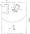
- Figs. 1A, 1B and 1C show respective top and side section views of a cavity 10, in accordance with an exemplary embodiment of the invention.
- Cavity 10 is a cylindrical cavity made of a conductor, for example a metal such as aluminum, and is resonant in the UHF or microwave range of frequencies, optionally between 300 MHz and 3 GHz, more preferably between 400 MHz and 1 GHZ.
- the cavity is a spherical, rectangular or elliptical cavity.
- the general methodology of the invention is not limited to any particular resonator cavity shape.
- feed antennas 16, 18 and 20 are positioned to feed energy at a frequency which is optionally chosen using the methods described below.
- Various types exemplary but not limiting antennae useful in carrying out the invention are shown in Figs. 4A-4C .
- one or more matching elements 22, 24 are placed inside the cavity, optionally near the feed antennas.
- Two types of field adjusting elements are shown, however, other shapes and materials can be used.
- First field adjusting element 22, shown more clearly in Fig. 2A is situated on end 12 of cavity 10.
- the element is rotatable about an axis 28 attached to the end, in a direction 30.
- it is insulated from the end by an insulating sheet 32 which couples element 22 capacitively to end 12.
- it is conductively attached.
- element 22 (as well as the other field adjusting element) has a dual effect, when properly adjusted. On the one hand it changes the modes of the cavity in a way that selectively directs the energy from the feeds into the object to be heated. A second and related effect is to simultaneously match at least one of the feeds and reduce coupling to the other feeds.
- Field Adjusting element 24, shown more clearly in Fig. 2B is situated between feed 18 and end 12.
- One end of the element optionally is electrically attached to cylindrical portion 14 of the cavity.
- the other end of element 24 is spaced and insulted from end 12 by insulating material 36. It is free to slide along end 12 and cylindrical portion as shown by arrows 33 and 34. This sliding changes the spectral variation of the energy absorption efficiency.
- Fig. 3 is a perspective drawing of the interior of the cavity to more clearly show the position and orientation of the feed and elements.
- Figs. 4A-4H show three different types of antennas that are useful in carrying out the invention. These antennas are either novel per se, or if known have never been used for feeds in a microwave oven or heater, especially in a cavity type heater. In general, in most microwave cavity type heaters, the feeds used are not directional to any great extent and not wideband, as defined in free air. The object of the feeds to excite the modes of the cavity. Since the cavities of the prior art are excited at a single frequency or a narrow band of frequencies, the antennas were designed specifically to excite these modes. In addition, prior art microwave cavities, use waveguides or loop antennas which are not designed to lower the coupling of energy from one feed to another (they generally have only a single feed). The present inventors have discovered that the use of directional antennae and/or wideband antennae allows for better coupling to the heated object and lower coupling to other feeds.
- the antennas are supplied as arrays. There are some advantages in using an antennas array.
- the band may be larger and there is a lower dependence of the heated object location on the results.
- the directivity may be controlled, even adjusted during heating. It is possible to control the phase of every single antenna of the array, controlling the RF mode. It is possible to alter the antenna structure, for example, using the helix antenna, the radius and the height of the antenna may be changed in order to tune the impedance and change the RF mode.
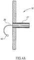
- Fig. 4A shows an antenna useful for coupling energy from feeds 16, 18 and 20 into cavity 10, in accordance with an embodiment of the invention.
- feed 16 includes a coaxial feed 37 with its center conductor 36 bent and extending into the cavity.
- the center conductor is bent but does not touch the walls of the cavity.
- the end of the wire is formed with a conductive element 40 to increase the antenna bandwidth.
- antennas of the type shown are able to couple energy better to an irregular object in the cavity. It is believed that such antennas transmit directionally and if the bend is aimed toward the object being heated, then coupling to the object (as opposed to coupling to the cavity) will be improved.
- Fig. 4B shows a helix antenna useful for coupling energy from feeds 16, 18 and 29 into cavity 10, in accordance with an embodiment of the invention.
- feed 16 include a coaxial feed 37 with its center conductor 36' having an extension that is formed into a helix.
- This antenna can be designed for matching into free space over a relatively wide band of frequencies (such as that useful for the present invention) and can be made more or less directional by changing the number of turns.
- the free space design is then adjusted for the presence of the cavity as described below with respect to Fig. 4C .
- the graph of Fig. 4C shows experimental results for a helix of 7 turns, with a diameter equal to the free space wavelength and a turn pitch of less than 0.2 wavelengths.
- the present inventors have found that curves of the type shown in Fig. 4C can be found, by experimentation, for other turn characteristics as well.
- Fractal antennas are known in the art. Reference is made to Xu Liang and Michael Yan Wan Chia, “Multiband Characteristics of Two Fractal Antennas ,” John Wiley, MW and Optical Tech. Letters, Vol. 23, No. 4, pp 242-245, November 20, 1999 . Reference is also made to G.J. Walker and J.R. James, “Fractal Volume Antennas” Electronics Letters, Vol. 34, No. 16, pp 1536-1537, August 6, 1998 . These references are incorporated herein by reference.
- Fig. 4D shows a simple bow-tie antenna 50 as known in the art, for radiation into free space.
- the Bandwidth of the bow-tie (in free space) is: 604MHz @ 740MHz center frequency (-3dB points) and 1917MHz @ 2.84GHz center frequency.
- This antenna has a monopole directivity pattern but a broadband one (being an advantage over the narrow BW of a dipole antenna).
- monopole directivity does not irradiate in a direction parallel to the feed.
- the band width (BW) of this antenna varies between 10MHz and maximum of 70MHz depends of the load (object) position inside the cavity.
- This and the following fractal antennas can be useful in the present invention to feed energy into a cavity.
- Fig. 4E shows a simple Sierpinski antenna 52, useful in the practice of the present invention.
- the cross-hatched areas 54 are metal plate and the white central area 56 is a non-conducting region.
- the metal plates are mounted on a preferably low dielectric constant dielectric and are connected at the corners and to center conductor 37 of coaxial feed 36, as shown. It's characteristics in the cavity are similar to those of the bow-tie antenna.
- Fig. 4F shows a modified Sierpinski antenna 58, useful in the practice of the present invention.
- the cross-hatched areas 60 are metal plate and the white areas 62 are non-conducting regions.
- the metal plates are mounted on a preferably low dielectric constant dielectric and are connected at the corners and to center conductor 37 of coaxial feed 36 as shown.
- the center frequency of this antenna is about 600 MHz inside the cavity.
- Fig. 4G shows yet another modified Sierpinski antenna 64, useful in the practice of the present invention.
- the cross-hatched areas 66 are metal plate and the white areas 68 are non-conducting regions.
- the metal plates are mounted on a preferably low dielectric constant dielectric and are connected at the corners and to center conductor 37 of coaxial feed 36.
- Fig. 4G Dimensions are shown on Fig. 4G for an antenna having a center frequency of 900 MHz in the cavity.
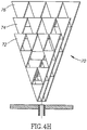
- Fig. 4H shows a multi-layer fractal antenna 70 made up of three fractal antennas spaced a small distance (e.g. 2 mm) from each other.
- each of these antennas is staggered in order to broaden the bandwidth of the antenna.
- a first antenna 72 is scaled to 0.8 of the dimensions given in Fig. 4G .
- a second antenna 744 has the same dimensions as the antenna of Fig. 4G and a third antenna 76 is increased in size over antenna 74 by a factor of 1.2.
- the volume fractal antenna ( fig. 4G ) has an overall bandwidth of 100MHz - this is an improvement over the 70 MHz maximum BW achieved in prior single fractal antenna ( figs. 4D-4H ).
- Fractal antennas also show a center frequency change when placed in a cavity. This difference is used (as with the helical antenna to design antennas for use in cavities by scaling the frequencies.
- antennas include patch antennas, fractal antennas, helix antennas, log-periodic antennas and spiral antennas.
- Figs. 5A to 5D are schematic block diagrams of an electromagnetic heating system, in accordance with an embodiment of the invention.
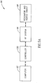
- Fig. 5A shows a general block diagram of each of the power feeds 90 of the system, in an exemplary embodiment of the invention.
- the system is controlled by a computer 92 which via a control interface (Controller) 130 controls an RF system 96 which provides power to the heated object 98.
- Controller controls an RF system 96 which provides power to the heated object 98.
- Fig. 5B is a block diagram of the electronics of one of the RF feed systems 96, in accordance with an exemplary embodiment of the invention.
- a VCO 102 receives a signal from a control circuit 130 ( Fig. 5C ) which sets the frequency of the energy into the port. This energy is passed through an RF switch 104 and a voltage controlled attenuator (VCA) 106, both of which are controlled by control circuit 130. After passing through the VCA, the power and frequency of the signal have been set.
- a load 108 is provided for dumping the signal generated by VCO 102 when the signal from VCO 102 is not switched to the VCA.
- the signal is then sent through the main line of an optional first dual directional coupler 110.
- the output of the VCA is then amplified by a power amplifier 112 and after passing though an isolator 114. A signal proportional to the power reflected from amplifier 112 is also fed to the control circuit.
- Coupler 110 feeds back a portion of the signal entering it (after detection or measurement of power) to control circuit 130.
- a signal proportional to the power reflected by amplifier 112 is also sent to controller 130.
- An RF switch 116 switches the power either to a load 118 or to the feed of resonator 98, via a second dual directional coupler 120.
- Dual directional coupler 120 samples the power both into and out of the resonator and sends power measurement signals to controller 130.
- RF amplifier 112 is a solid state amplifier based on the LDMOS technology.
- Psat 300W
- Efficiency about 22%
- Effective band - 800-1000MHz Such amplifiers either have a relatively narrow bandwidth or a low efficiency ( ⁇ 25%) or both. This limits the optimal utility of the advances of the present invention.
- amplifiers have become available based on SiC (silicon carbide) or GaN (gallium nitride) semiconductor technology. Transistors utilizing such technologies are commercially available from companies, such as Eudyna, Nitronex and others.
- Amplifiers having a maximum power output of 300-600 W can be built from low power (50-100 Watt) modules) and a bandwidth of 600 MHz (at 700 MHz center frequency) or a bandwidth of 400 MHz (at 2.5 GHz center frequency are available, for example.
- Such amplifiers have a much higher efficiency than prior art amplifiers (efficiency of 60% is available) and much higher tolerance to reflected signals, such that isolator 114 can often be omitted for these amplifiers.
- a particular configuration utilizing this type of amplifier is described below in conjunction with Figs. 12A-D .
- controller 130 comprises computer 92 which performs computations and provides a logging function of the system as well as acting as a user interface. It also controls the rest of the elements in performing the calibration and control method of the flow charts of Fig. 7 .
- Computer 132 is coupled to the rest of the system through an interface 134 which is designed to provide communication to, for example, an ALTERA FPGA 140, which interfaces with and provides control signals to the various elements of the RF system.
- the Altera receives inputs (as described above with respect to Figs. 5A-5C ), via one or more multiplexers 136 and an A/D converter 138. In addition, it sets the frequency and power of each of the feeds (also described with respect to Figs. 5A and 5B ) via D/A converters 140 and the positions of the field adjusting element optionally utilizing the method described with aid of the following flow charts.
- the computer may not be necessary and the Altera or a similar controller may control and process all the necessary data.
- the frequency is swept as described below.
- Fig. 6 is a simplified flow chart 150 of the operation of a heating system having the structure described above.
- Fig. 7 is a simplified flow chart of calibration 160 of the system. As will be evident, the method operation and calibration of the system is also usable with only minor changes for operating systems with lesser or greater numbers of power feeds and/or a greater or less number of matching elements.
- an object for example a frozen organ or frozen or non-frozen food object
- a calibration or adjustment routine is then optionally performed to set the variable elements in the system. These can include power output of the amplifiers 112 in each of the power feeds to the cavity at each frequency, chosen to be transmitted, the finite set of sub-bands of frequencies of each VCO 102, the method of providing energy at the various frequencies (for example sweep or other frequency variation, or the provision of a pulsed signal embodying the desired frequency and power characteristics), positioning of the matching elements (e.g., 22, 24), position of the heated object and any other variables that affect the various characteristics of the heating process, for example - the uniformity and/or efficiency of power transfer to the object.
- a memory contains the criteria 156 for calibrating the system. Exemplary criteria are described below. Calibration is carried 160 out to determine the new heating variables.
- An exemplary calibration routine is outlined in the flow chart of Fig. 7 , discussed below.
- the new variables are set 158 and heating commences 170.
- the heating Periodically (for example a few times a second), the heating is interrupted for a short time (perhaps only a few milliseconds or tens of milliseconds) and it is determined 154, optionally based on a method described below, whether heating should be terminated. If it should, then heating ends 153. If the criterion or criteria for ending heating is not met, then the calibration (or re-adjustment) routine 160 is entered. If not, the heating 170 is resumed. It is noted that during the measurement phase, the sweep is generally much broader than during the heating phase.
- the power is optionally set at a level low enough 162 so that no substantial heating takes place, but high enough so that the signals generated can be reliably detected.
- calibration can take place at full or medium power. Calibration at near operational power levels can reduce the dynamic range of some components, such as the VCA, and reduce their cost.
- Each of the inputs is then swept 164 between a minimum and a maximum frequency for the channel.
- the upper and lower frequencies are 430 and 450 MHz.
- Other ranges, such as 860-900 MHz and 420-440 can also be used. It is believed that substantially any range between 300-1000 MHz or even up to 3 GHz is useful depending on the heating task being performed.
- the broadband, high efficiency amplifiers described above are used, much larger bandwidth of several hundred MHz or more can be swept, within the range of the amplifiers.
- the sweep may be over several non-contiguous bands, if more than one continuous band satisfies the criteria for use in heating.
- the present inventor has found that under many operating regimes it is desirable to maximize certain criteria.
- the maximum net power efficiency for each port is maximized, in the sense, that the net power efficiency at a point of maximum efficiency within the sweep range is made as high as possible.
- the efficiency and the frequency at which the efficiency is a maximum is noted.
- the width of the efficiency peak and a Q-factor are noted as well.
- a second embodiment of the invention is based on a similar criterion.
- the area under each resonance peak of the net efficiency of transfer is determined. This area should be a maximum.
- the efficiency, the center frequency of the resonance having the maximum area and its width are noted.
- the criteria for determining if the variables are properly set is when the peak net efficiency (first embodiment) or the area or a width (second embodiment) is above some predetermined level or a Q-factor is below some predetermined level. For example, there may be a restriction that the area above 60% net efficiency is maximized for each of the feeds.
- the frequency is swept, optionally while adjusting the power.
- the term swept should be understood to include serial transmission of individual non-contiguous frequencies, and transmission of synthesized pulses having the desired frequency/power spectral content.
- each frequency has maximal absorption at a specific location within an object within a cavity, which locations may vary between different frequencies. Therefore sweeping a range of frequencies may cause movement of the peak heating region within the object.
- Computer simulations have shown that, at least when the Q factor of a peak is low (i.e., a lot of energy is dissipated in the object being heated) the movement of the peak heating region can be quite substantial.
- each mode represented by a different peak of efficiency acts differently when swept.
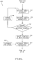
- Fig. 11A is a simplified flow chart 200 of a method of determining swept power characteristics, in accordance with an embodiment of the invention. This method corresponds to acts 160 and 158 of the flow chart of Fig. 6 .
- the cavity After placing the object in the cavity (152) the cavity is swept to determine the input efficiency as a function of frequency (202) (e.g., obtain a spectral image). Determination of input efficiency is described in detail above.
- a pulse of energy, having a broad spectrum in the range of interest is fed into the input.
- the reflected energy and the energy transmitted to other inputs are determined and their spectrums are analyzed, for example using Fourier analysis.
- the net power efficiency as a function of frequency can be determined.
- Fig. 11B shows a simplified net power efficiency curve 250 at an input. It is noted that there are regions in which the efficiency is high and others in which the efficiency is low. Furthermore, some of the efficiency peaks are broader and others are narrower..
- the overall swept bandwidth (BW) is determined (204). This may include sweeping across a single peak or across several peaks.
- the frequency is swept across a portion of each of the high efficiency peaks.
- the power inputted to the cavity at each frequency should be the same.
- the power at each frequency is adjusted such that P* ⁇ is a constant for all the frequencies in the sweep. Since the power available is always limited to some value, this may set a limit on the available bandwidth for the sweep. An example of a lower limit to efficiency is shown as dashed line 252 in Fig. 11B .
- the sweep may be limited to frequencies having efficiency above this value.
- the positions of the field adjusting elements are set. This adjustment is optional and in some situations, even where such elements are present, they do not need to be adjusted.
- the criterion for such adjustment is that the peaks have as high efficiency as possible with as broad a peak as possible
- Specific applications may introduce additional goals, such as moving the peak to a certain band.
- An iterative process (206, 208) is used to determine a desired position and/or orientation of the field adjusting elements.
- the search process which may be any iteration process as known in the art, is completed the elements are set to the best position found. (210).
- the sweep is adjusted (212) to avoid feeding excess power into certain parts of the object.
- the object contains a metal rod or a metal zipper
- a high peak in efficiency 254 may be generated.
- a metal rod can cause a concentration of energy near the ends of the rod. Avoiding irradiation at this peak can sometimes reduce the effects of such objects on even heating.
- Fig. 11C shows the power spectrum 256 of energy to be fed to the input, in accordance with an embodiment of the invention. It should be noted that no energy is transmitted at the frequency characteristic of the rod and that for other frequencies for which the efficiency is above the minimum shown at 252 in Fig. 11B .
- the power has a shape that is such that the product of the efficiency ⁇ and the power fed is substantially constant.
- the energy is fed to the port in the form of a pulse rather than as swept energy.
- a pulse such as that shown in Fig. 11C is generated by a pulse synthesizer. This pulse is amplified and fed into the input. The pulse synthesizer would then replace VCO 102 ( Fig. 5B ). It is understood that the pulse synthesizer can also be programmed to produce a sweep for use in determining the frequency dependence of ⁇ (act 164 of Fig. 7 ).
- a search is performed for a position of the matching elements at which the net power efficiency at all of the feeds meets the criteria. This is indicated at boxes 214 and 216, which represent a search carried out by changing the positions and/or orientations of the matching elements. Standard search techniques can be used (iteration) or a neural network or other learning system can be used, especially if the same type of object is heated repeatedly, as is common for industrial uses.
- the power is raised to a level suitable for heating and optionally swept.
- the power into the respective amplifiers is optionally normalized to provide a same net power into the cavity (and therefore, into the object) for each port.
- the least efficient port determines the power to the object. While in prior art ovens, the user decides on the heating time, in some embodiments of the present invention the desired heating time can generally be predicted.
- power is fed to all of the feeds at the same time. This has the advantage that heating is faster. It has the disadvantage that three separate sets of circuitry are needed.
- the power is fed to the feeds seriatim, for short periods. Potentially, only a single set of most of the circuitry is needed, with a switch being used to transfer the power from feed to feed. However, for calibration, a method of measuring the power transmitted from port to port should be provided. This circuitry could also be used to match the feeds when power is not being fed to them.
- Fig. 8 A different type of circuitry for providing both the heating and calibration functionality, in accordance with an embodiment of the invention, is shown in Fig. 8 , corresponding to the circuitry of Fig. 5B .
- Fig. 8 is similar to Fig. 5B up to the output of RF switch 116. Following RF switch 116 a second RF switch 192 transfers the power delivered by amplifier to one of the feeds. Only circuitry 200 related to feed 2 is shown.
- Circuitry 200 operates in one of two modes.
- a signal from control 130 switches power from RF switch 192 to dual directional coupler 120, via an RF switch 194.
- the rest of the operation of the port is as described above.
- a passive mode the input to RF switch 194 does not receive power from amplifier 112.
- Switch 194 connects a load 190 to the input of dual directional coupler 120.
- load 190 absorbs power that is fed from the cavity into the feed.
- additional simplification of directional coupler 120 may be possible, replacing the dual directional coupler with a single directional coupler.
- switches 116 and 192 and optionally the local switches can be combined into a more complex switch network.
- RF switch 194 can be replaced by circulator such that power returned from the feed is always dumped in load 190.
- the frequency of the power fed to a port can be fed at the center frequency of the resonance mode that couples the highest net power, i.e., the point of maximum efficiency of energy transfer to the object being heated.
- the frequency can be swept across the width of the resonance or, more preferably along a portion of the width, for example between the -3 dB points of the power efficiency curve, or as described above with respect to Figs 11A-11C .
- the power is adjusted during this sweep so that the net input power remains constant or more nearly constant during the sweep. This can be accomplished by changing the power amplification of the power amplifier inversely to the power efficiency of the instantaneous frequency being fed.
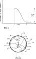
- Fig. 9 shows a graph of frequency of a particular peak with time for a typical thawing process. This graph illustrates one method of using the changes in the properties of the object during a thawing process to determine when the process is complete.
- the ordinate of Fig. 9 is the frequency chosen as an input for one of the feeds.
- the abscissa is time.
- the ice in the object turns to water. Ice and water have different absorption for microwave or UHF energy, resulting in a different return loss and coupling as a function of frequency. Not only does this change the match, but at least after rematching by adjustment of the matching elements, the frequency of the absorption efficiency peak changes.
- point A some of the ice has started to change into water and the frequency of match changes.
- point B all of the ice has changed to water and the frequency of match stops changing.
- the point at which all of the ice is turned into water can be determined and the heating terminated, if only thawing is desired. It is noted that the frequency change during thawing is large, as described herein, compared to allowed frequency changes in the prior art.
- Heating methods and apparatus of the present invention which allow for both even heating and provide knowledge of the progress of the thawing, can result in much lower or even non-existent re-crystallization.
- Apparatus and method according to the present invention have been used to defrost a pig's liver, Sushi or Maki and to cook an egg in the shell.
- Table 1 Comparison of Inventive Method and Conventional Microwave- Cow Liver Measurement Inventive Method Conventional Microwave Initial Temperature -50°C -50°C Final Temperature after thawing 8°C to 10°C -2°C to 80°C Power 400 Watt 800 Watt Thawing time 2 Minutes 4 Minutes Visible damage None The texture of the thawed sample was destroyed. There are frozen regions along side burned ones. No chance of survival of living cells.
- Table 2 shows a comparison between thawing of Maki containing raw fish covered by rice and wrapped in seaweed, by the system of the present invention and using a conventional microwave oven.
- Table 2 Comparison of Inventive Method and Conventional Microwave-Maki Measurement Inventive Method Conventional Microwave Initial Temperature -80°C -80°C Final Temperature after thawing 2°C to 6°C -5°C to 60°C Power 400 Watt 800 Watt Thawing time 40 Seconds 1 Minute Visible damage None The thawing process cooked part of the salmon, therefore it was not Maki anymore.
- An egg was cooked using the present method. Generally, eggs burst if an attempt is made to cook them in a microwave oven. However, using the system described above an egg in the shell was cooked. The white and yellow were both well cooked, and the white was not harder than the yellow. Neither part was dried out or rubbery and the taste was very good, with little if any difference from a conventional hard cooked egg. In addition, deep frozen fish have been defrosted without leaving any frozen portions and without any portions being heated above cooking temperatures.
- Thawing objects such as meat and fish with such low differences and at high speed has the potential for prevention of development of salmonella, botulism and other food poisons. Controlled, uniform thawing has important implications in thawing organs for transplanting, without tissue destruction.
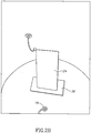
- Fig. 10 shows apparatus for applying a DC or relatively low frequency (up to 100 kHz or 100 MHz) to an object in the cavity, in accordance with an embodiment of the invention.
- This figure is similar to Fig. 1 , except that the cavity includes two plates 250 and 252.
- a power supply (not shown) electrifies the plates with a high differential voltage at DC or relatively low frequency.
- the objective of this low frequency field is to reduce the rotation of the water molecules. Ice is water in a solid state therefore its rotational modes are restricted. A goal is to restrict the rotational modes of the liquid water in order to make the heating rate be determined by that of the ice.
- the present inventors also believe that the low frequency fields may change the dielectric constant of the materials making up the object being heated, allowing for better match of the input to the object.
- a DC or low frequency magnetic field is applied by placing one or more coils inside or preferably outside the cavity to cause alignment of the molecules in the object. It is possible to combine low frequency or DC electric and low frequency or DC magnetic fields with possible different phases from different directions.
- Fig. 12A shows a cavity 98 with an internal heater coil 600 placed inside the cavity.
- An inlet 602 and an outlet 604 allow for feeding a hot fluid through the coil to heat the air within the cavity.
- Figs 12B and 12C show two schematic illustrations of a system for transferring heat from a high power amplifier 606 to the coil. Even at an efficiency of 60%, the amplifier can generate several hundred watts. This energy (or at least a part of it) can be transferred to heat the air and to produce infrared radiation (as a resistive coil does) in the cavity to increase the efficiency of heating.
- Fig. 12B shows a very schematic diagram to illustrate how waste heat from an amplifier 606 can be captured.
- Fig. 12C shows a block diagram of the same system.
- Element 608 represents a cooling system for returning fluid and a fluid pumping system. It receives return fluid from outlet 604, cools the liquid (if necessary) and pumps the liquid into a gap 610 between the between amplifier 606 and an optional heat sink 612. The temperature at the input to the gap and at its output are preferably measured by sensors 614 and 616 and fed to a control system 618, which controls one and optionally more than one of the cooling and pumping rate to provide a desired heat transfer to the cavity.
- a fan 620 may be provided to cool the heat sink as necessary.
- the fluid passing between the amplifier and the heat sink also functions to transfer heat from the amplifier and the heat sink.
- heat conducting rigs may transfer heat between the amplifier and the heat sink with the fluid passing between the ribs to collect heat.
- heat pipes or other means can be used to collect and transfer energy to the cavity.
- hot air could be passed over the amplifier and/or heat sink and passed into the cavity.
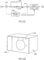
- a heater as shown in Fig. 12D including a housing 650, amplifiers and controller, as well as a user interface 652 and a door 654, as normally found on a microwave oven can weigh as little as 10 or 15 Kg or less.
- UHF frequencies are absorbed preferentially by ice and have a longer wavelength than the higher frequencies, so that the fields within the object are more uniform and the ice is preferentially heated as compared to the water. This provides for preferential heating of the ice and more even thawing.
- Such probes may be included in a bag in which the object to be heated is placed and may include a resonant element whose resonant frequency is made to vary with temperature by the inclusion of a temperature dependent element such as a temperature dependent resistor or capacitor.
- Probes may be provided with resonant circuits whose frequency depends on temperature. Such probes may be scanned during the scanning used for setting sweep parameters to determine temperature. During power transfer, these frequencies should generally be avoided.
- a temperature sensitive tag is paired with a temperature insensitive tag and the changes in the frequency of the temperature sensitive tag are determined by a difference frequency between the two. This allows for a more accurate measurement of temperature that utilizing an absolute measurement of the frequency of the temperature sensitive tag.
- Wrapping of the sample in material that does not absorb EM radiation at the specified frequencies This type of wrapping can serve as packaging for the sample during transportation and as part of the probe system by which it is possible to measure temperature and additional parameters at the edges of the sample. This wrapping can serve as local refrigeration for the outer surfaces of the sample (which usually have a tendency to warm faster than the rest of the sample) in order to achieve uniformity in the warming of the sample.
- the wrapping can include identification of the object to help track the object and also to provide an indication to the system of a preferred protocol for heating the object.
- the wrapping may be provided with a number of resonant elements which can be detected when the cavity is swept during calibration. The frequencies of the elements can be used to provide an indication of the identity of the object. This allows for the automatic or semi-automatic setting of the starting parameters for calibration and/or for a particular heating protocol, optimized for the particular object and conditions.
- a recording/storage element of a different type is provided, for example, in the form of an RFID element or a bar-code, which includes thereon an indication of the content of a package or wrapper including the object, suggested treatment thereof and/or heating instructions.
- the instructions are actually provided at a remote site, indexed to a key stored by the recording element. Such instructions may be, for example, stored in a table or generated according to a request, based on information associated with the identification.
- a reader is optionally provided in the heater, for example, an RFID reader or a bar-code reader to read information off a package or a wrapper thereof.
- various types of information are optionally stored on (or in association with) the recording element, for example, size, weight, type of packing and/or cooking/thawing/heating instructions.
- the recording element has stored therewith specific cooking instructions.
- the recording element has stored therein information regarding the platter shape and/or dielectric properties of its contents. It is noted that for industrial shaped portions, if the shape of the food is relatively regular between platters, movement of the food and/or changes in size and/or small changes in shape will not generally affect the uniformity by too much, for example, shifting a heating region/boundary by 1-2 cm.
- the platter includes a depression and/or other geometrical structures which urge the food item to maintain a desired position relative to the platter borders.
- the parameters of the heating are optionally varied.
- the effect of the varying may cause non-uniformity in space and/or in time.
- a script is provided which defines how and what to vary.
- the script includes decisions made according to time (e.g., estimation of an effect) and/or food state (e.g., measurement). Various measuring methods are described above. Estimation is optionally based on a simulation or on empirical results from previous heating cycles.
- the script is conditional (e.g., modified, generated and/or selected), for example, based on the position of a platter in the oven and/or personal preferences (which may be stored by the oven).
- a script is provided on the recording element or at a remote location.
- a script is selected by a user selecting a desired heating effect.
- a single food item may experience different power levels for different times, in order to achieve a desired texture/flavor.
- a script is used to set different energy levels and/or different times to apply such energies.
- a script is as follows:
- the script includes other conditions, for example, detecting changes in color (e.g., browning), steaming (e.g., by phase change of water), volume (e.g., dough rising will change the behavior of the cavity in ways that can be anticipated).
- changes in color e.g., browning
- steaming e.g., by phase change of water
- volume e.g., dough rising will change the behavior of the cavity in ways that can be anticipated.
- the script includes a request to the user to add ingredients (e.g., spices), or to mix or reposition object.
- ingredients e.g., spices
- the script takes into account the quality of uniformity control achievable by the oven. For example, if a higher level of uniformity is desired than basically provided by the oven, heating may include pauses where power is reduced, to allow heat to even out in the object. The length of the delays is optionally pre-calculated for the food substances and a calibrated lack of uniformity of the oven. Alternatively or additionally to reducing power, the food and/or the heating areas may be moved one relative to the other so as to better distribute heating.
- no script is provided. Instead, the heating times and/or parameters are based directly on the desired results, measured food properties and/or measured heating properties. Such desired results may be user provided or indicated by the recordable element.
- the present invention has been described partly in the context of thawing.
- the inventors believe that based on the results shown above, it can be expected that the methods of the present invention, can be used for baking and cooking, areas in which conventional microwave ovens are notoriously weak or for other heating operations, especially those for which a high level of uniformity or control is needed and/or in which a phase change takes place.
- the UHF or microwave energy may be deposited uniformly in an object to within less than ⁇ 10%, ⁇ 20% or ⁇ 30% over 80% or 90% or more of the object.
Description
- The present invention is concerned generally with heating of materials with electromagnetic energy.
- The microwave oven is a ubiquitous feature in modern society. However, its limitations are well known. These include, for example uneven heating and slow absorption of heat. In fact, ordinary microwave ovens, when used for heating (e.g. defrosting), cause temperature differences as high as 100°C between different locations in the heated object, resulting in creation of hotspots, regions of thermal runaway. Fore example, frozen foods that are thawed in a microwave oven may have one or more part (e.g. the outside) that is warm or even partly cooked before or other parts (e.g. in the interior) are even defrosted. Also known are hotspots that occur within a heated cup of liquid that may result in personal injury to a user. One common method that attempts to reduce hot-spots is to rotate the article being heated. This method does not provide uniform heating as would be desired.
- One method of providing uniform heating is to allow the heat deposited in a hot spot to diffuse to surrounding regions and heat them by conduction. Such methods may include a intermittent heating procedure in which the heating is periodically stopped to allow diffusion of heat. While this method may be used in conjunction with the methods of the present invention, by itself the stop and go method of heating is either extremely slow (due to the low heat conductivity of most foods, which require long stop periods to make the method effective) or are relatively ineffective. Another method is to heat at a very low power. This can be used, for example, with large frozen bodies. If the heating is slow enough, then the excess heat at hot spots diffuses before the temperature rise at the hot spot becomes objectionable. However, this method requires up to 10 or 20 times as much time for heating to be fully effective. Due to convection from the object, it is not a serious option for cooking or heating much above room temperature.
- A number of papers have been published in which a theoretical analysis of the problem of microwave warming of a cryogenic sample has been carried out. Because of the difficulties of such analysis, such analysis has only been carried out on regular shapes, such as spherical and ellipsoidal shapes. Experimental attempts have apparently been made on kidney sized specimens, but results of these experiments do not indicate that a viable solution for defrosting kidneys is available.
- Moreover, there does not appear to be a solution for defrosting other organs, or for defrosting warming or cooking foods, of more arbitrary shapes.
- S. Evans, Electromagnetic Rewarming: The effect of CPA concentration and radio source frequency on uniformity and efficiency of heating, Cryobiology 40 (2000) 126-138
- S. Evans, et al., Design of a UHF applicator for rewarming of cryopreserved biomaterials, IEEE Trans. Biomed. Eng. 39 (1992) 217-225
- M.P. Robinson, et al., Rapid electromagnetic warming of cells and tissues, IEEE Trans. Biomed. Eng. 46 (1999) 1413-1425
- M.P. Robinson, et al., Electromagnetic re-warming of cryopreserved tissues: effect of choice of cryoprotectant and sample shape on uniformity of heating, Phys. Med. Biol. 47 (2002) 2311-2325.
- M.C. Wusteman, Martin et al., Vitrification of large tissues with dielectric warming: biological problems and some approaches to their solution , Cryobiology 48 (2004) 179-189.
- A paper entitled "Control of Thermal Runaway and Uniformity of Heating in the Electromagnetic Warming of a Cryopreserved Kidney Phantom" by J. D. J. Penfold, et al., in Cryobiology 30, 493-508 (1993) describes a theoretical analysis and experimental results. While some experiments were apparently made with a kidney sized phantom, the main reported results are with a uniform spherical object.
- As reported a cavity was fed with electromagnetic energy at 434 MHz from three orthogonal directions (x, y, z). The x and y feeds were provided from a same generator and a phase change was introduced so that the field was circularly polarized. The frequency was varied in steps of 32 kHz (apparently up to about 350 kHz maximum) to match the input impedance as it changed with increasing temperature.
-
WO 02/23953 - The present inventors have realized that the measures taken by prior art investigators to provide uniform heating were inadequate and could not, by
themselves, lead to a viable methodology for uniform heating (or defrosting) of irregular shaped objects such as organs, foods or the like. In particular it was discovered that the prior art suffered from many problems. As used herein, the term irregular means objects that depart from spherical or ellipsoid shape by more than 5% RMS volume. - Conventional microwave ovens are configured to feed into the oven chamber microwave energy that is essentially of a single frequency. Due to device constraints the energy is fed at different frequencies in a small range, normally between 2.4 and 2.5 MHz. The inventors realized that the constraints of using a substantially constant frequency, or even tracking a single dissipation peak in a small frequency range, significantly limited the ability to achieve uniform heating. In fact, heating at a single frequency is found to be one of the main reasons of hotspots. However, using different frequencies (using one or more feeds), may improve the uniformity of heating.
- While some proposed prior art heaters did utilize more than one microwave input, the frequency differences between the two inputs are small, less than 6 MHz.
- The inventors also found that the structure of the cavity of a conventional microwave oven, and especially the mode structure of the cavity, inherently did not allow achievement of uniform heating. In general, the fields for a given mode in a cavity vary with position and the heating varies with the strength of the fields.
- In the art, attempts were made to set the parameters of the microwave oven to match features of a heated object before heating begins. However, during heating features of a heated object (e.g. the tendency to absorb energy of a given frequency) change. Hence the inventors realized that even if a heater was tuned to a heated object before operation, after even a short period of operation the features of the object will have changed and the tuning will no longer be significant.
- Another problem is that at times, the absorption at a given location of an object is higher as the temperature increases. This can give rise to a "thermal runaway" problem (even in conventional microwave oven), wherein a relatively hot place absorbs more than a colder one thus continuously increasing the temperature difference. When an effort is made to tune the energy input of the device to the object's impedance, the efficiency of energy delivery into the object may be maximized, but hotspots are also generally increased.
- The inventors also noted that known publications dealing with dissipation of energy deal with absorption of energy by the resonator (e.g. surface currents) and not necessarily the object. Furthermore, no attention was drawn to the distribution of dissipation of energy in the object (with the exception of some discussion of penetration depth).
- Furthermore, when feeding from multiple directions into a cavity, coupling between the feeds can be a major problem. While for spherical samples these effects are minimal, for even moderate variations from this shape, the coupling between inputs can be quite large. Such coupling caused a number of problems including uneven heating and low power efficiency.
- Some exemplary embodiments of the invention deal with one or more of these problems
As used herein the term "heating" means delivering electromagnetic (EM) energy into an object. At times, an object may be heated according to the present invention without temperature increase (e.g. when it is concomitantly cooled at a rate that is at least equal to the heating rate or at a phase change where the transmitted energy is taken up for the phase change). Heating includes thawing, defrosting, heating, cooking, drying etc, utilizing electromagnetic energy. - Aspects of the invention are set out in
independent claims - An aspect of some embodiments of the invention is concerned with sweeping the frequency of the feed (or feeds) over a finite set of frequency sub-bands (i.e. feeding energy into the heater over many frequencies belonging to each sub-band). For example, the dissipation of energy is measured for a band of RF frequencies (e.g. the whole operation range of the heater), and based on the measured results, a finite set of frequency sub-bands is selected. The width of band over which the energy efficiency is measured may for example be up to 2 GHz. At times, the band may have a width between 0.5% (5/1000 [MHz]) and 25% (100/400 [MHz]) of the center frequency.
- The measurement may be performed before heating an object, at one or more times during heating the object, or in advance (with a sample object to define the sub-bands for additional essentially identical objects). In an embodiment of the invention, RF energy is fed to the cavity at a plurality of frequencies and power levels responsive to the wnwegy efficiency measurements. For example, the input may be frequency swept. Other methods described below may also be used.
- The power coupled to other feeds at each frequency in certain band (Sij) and the return loss at each frequency (Sii) are taken into account in determining the heating efficiency and in adjusting certain characteristics of the apparatus, for example, a decision what power at what frequencies to transmit and the timing of transmitting those frequencies at matching powers. Optionally, the absorbed power (input power less coupled power) fed into the system from one feed is adjusted to be the same as the absorbed power fed into each of the other feeds.
- In some embodiments of the invention, a wide band solid state amplifier may be used as an RF energy source. Among the potential benefits is the wide band of frequencies that may be introduced by the solid state amplifier.
- In an embodiment of the invention, at least one field adjusting element is placed in the cavity to improve one or more parameters of the heating process (e.g., coupling). Optionally more than one field adjusting element is used. Optionally, any of the boundaries of at least one of the field adjusting elements is electrically floating (not touching the metal walls of the cavity). Optionally any part of the boundaries of at least one element are attached to one of the walls of the cavity. In an exemplary embodiment of the invention, at least one of the elements is not fixed in place, so that it can be moved and/or rotated and/or folded/unfolded to improve one or more parameters of the heating process. In an exemplary embodiment, of the invention, at least one of the elements rotates about an axis. In an exemplary embodiment of the invention, the at least one element slides along a wall of the cavity.
- In an exemplary embodiment of the invention the field adjusting element is a metal or other conductor. Alternatively, any material, such as a dielectric, optionally loaded with metal, which is known to perturb electromagnetic fields, can be used as a matching element. The size, structure, place and material of a field adjusting element may affect the effectiveness of the field adjusting element. The effect of the size is dependent also on the location of the element. At one location the effect of the element on the measured energy transfer and other heating parameters and in another it is not. In general, when the element is in the direction of the directivity of the antenna it has a relatively large effect.
- Additionally, the relation of height to radius of a chamber, and the geometric design (e.g. box shape vs. cylinder shape) are known affect the dissipation pattern of the chamber and the modes within the chamber. In designing a device according to some embodiments of the present invention, a simulation or trial error measurement of dissipation may be used to select a chamber being better suited, e.g. having wider dissipation peaks (low Q factor) in the object, or more adaptable (i.e. enabling a more dramatic change of the dissipation pattern, using similar field adjusting elements, for example as detailed below) for the desired heating.
- There is further provided, in accordance with an embodiment of the invention, a method of electromagnetic heating, comprising:
- subjecting an object that is to be heated to UHF or microwave energy in an amount capable of heating the object;
- determining a characteristic of the heating process that is responsive to a change in state of the object; and
- adjusting the heating when a desired state is achieved.
- Some embodiments include determining an amount of energy that is absorbed by the object and adjusting the heating when a desired amount of energy is absorbed.
- Exemplary non-limiting embodiments of the invention are described below with reference to the attached figures. The drawings are illustrative and generally not to an exact scale. The same or similar elements on different figures are referenced using the same reference numbers.
-
Figs. 1A, 1B and 1C are respective schematic top and side section views of acavity 10, in accordance with an exemplary embodiment of the invention.; -
Figs. 2A and2B show two exemplary matching elements, in accordance with an embodiment of the invention; -
Fig. 3 is a schematic isometric drawing of the interior of the cavity ofFig. 1 ; -
Fig. 4A is a schematic drawing of an antenna useful for coupling energy into the cavity, in accordance with an embodiment of the invention; -
Fig. 4B is a schematic drawing of a helical antenna useful for coupling energy into the cavity, in accordance with an embodiment of the invention; -
Fig. 4C shows a graph of correlation of free space matched frequencies and cavity matched frequencies of a helical antenna feed; -
Fig. 4D-4H are schematic drawings of various fractal antenna useful for coupling energy into the cavity, in accordance with an embodiment of the invention; -
Figs. 5A-5C are schematic block diagrams of electromagnetic heating systems, in accordance with an embodiment of the invention; -
Fig. 6 is a simplified flow chart of the operation of the system, in accordance with an embodiment of the invention; -
Fig. 7 is a flow chart of a process of adjusting elements and frequency in the heating system illustrated inFig. 5 , in accordance with an embodiment of the invention; -
Fig. 8 illustrates alternative RF circuitry, in accordance with an embodiment of the invention; -
Fig. 9 is a graph of frequency vs. time for a typical thawing process, illustrating an automatic turn-off capability in accordance with an embodiment of the invention; -
Fig. 10 shows the layout of a low frequency bias structure, in accordance with an embodiment of the invention; -
Fig. 11A is a simplified flow chart of a method of determining swept power characteristics, in accordance with an embodiment of the invention; -
Figs. 11B and 11C illustrate how a swept power spectrum is determined, in accordance with an embodiment of the invention; -
Fig. 11D shows a pulse shape, for a pulse operative to provide the spectrum shown inFig. 11B , in accordance with an embodiment of the invention; -
Fig. 12A shows an RF heater with an auxiliary heating coil;, in accordance with an embodiment of the invention; -
Figs. 12B and12C schematically illustrate a scheme for transferring waste heat from an amplifier to the heater ofFig. 12A ; and -
Fig. 12D shows an external view of a low weight, high efficiency RF heater, in accordance with an embodiment of the invention. - The present application describes a number of advances in the field of RF heating (e.g. microwave or UHF) heating. While, for convenience these advances are described together in the context of various apparatus and methods, each of the advances is generally independent and can be practiced with prior art apparatus or method (as applicable) or with a non-optimal version of the other advances of the present invention. Thus, for example, parts of the method of adjusting the input power can be used with the prior art apparatus of Penfold, et al., referenced above. Conversely, the inventive apparatus of the present invention (or parts thereof) can be used with the method of Penfold et al. It is expected that these combinations will not be ideal, but they are expected to give improved results over the prior art apparatus and methods.
- Furthermore, advances described in the context of one embodiment of the invention can be utilized in other embodiments and should be considered as being incorporated as optional features in the descriptions of other embodiments, to the extent possible. The embodiments are presented in somewhat simplified form to emphasize certain inventive elements. Furthermore, it is noted that many features that are common to most or all embodiments of the invention are described in the Summary of the Invention and should also be considered as being part of the detailed description of the various embodiments..
- The following are believed to novel features or variations present in some or all the embodiments described. It is understood that not all of these features may be present in any particular embodiment and that not all features are described for every embodiment for which they are applicable.
- 1) An apparatus and method that allow for RF heating an irregular object such that the temperature of the object is uniform within 50°C (optionally, to within 10, 6, 4 or 2 °C) when heating is completed. Exemplary embodiments provide this uniformity mainly by directly RF heating the object such that over 50% of the heating is by direct RF heating and not by conduction from other portions of the device. In some embodiments of the invention, such direct RF heating can reach 70, 80, or 90 or more percent.
- 2) An apparatus that includes field adjusting elements inside the cavity and method of designing and using same.
- 3) A heating apparatus with one or more coupling antenna for coupling energy into the cavity; a method of designing said antenna; and method of feeding energy to the heater including a method of tuning the radiated pattern of the antenna. This includes, utilizing an antenna array (with one or more feeds, having controlled phases), loop antenna, wide band antenna, fractal antenna, directional antenna, helix antenna, operating the antennas separately or coherently, designing the antenna to obtain a desired radiated pattern etc.
- 4) An apparatus and method to gain knowledge of a heating process before, and potentially also several times during, heating (e.g. several times a second) using a measurement of the efficiency of absorption of energy in the object being heated as function of frequency
- 5) An apparatus and method that is adapted to control one or more characteristics of the heating process, for example the amount of power absorbed in the heated object, based on the measurement of energy absorption efficiency (e.g. by transmitting power to compensate for the variations of energy absorption). This may be done by adjusting, for example, input power at each transmitted frequency and/or choosing frequencies to be transmitted and/or moving the field adjusting element's and/or moving the heated object and/or changing the antennas characteristics. This may be done before operation, and preferably also one or more times during operation (e.g. several times a second), based on measurements of energy absorption during heating or during a short hiatus in the heating.
- 6) An apparatus and method for applying a DC or low frequency electric (e.g. below 300MHz, or below some other value substantially lower that the heating frequencies used) or magnetic field to the object during RF heating. Such application is believed to change the dielectric properties of the object being heated and this provides yet another method of adjusting the power provided to the object being heated.
- 7) An apparatus and method in which during operation the transmitted frequencies and/or power from one or more feeds are varied in a controlled manner to get a desired heating pattern (e.g. by more than 1, 2 or 5 MHz). This variation may occur several times during operation (e.g. several times a second). In an embodiment of the invention, the desired pattern is a uniform heating pattern.
- 8) Apparatus and method of controlling heating based on reading of dielectric characteristics of the heated object. Reading may be obtained one or more times during heating (e.g. several times a second). For example end of thawing or boiling process, when a phase change is sensed. This can implement a cessation of heating.
- 9) An electromagnetic heater including multiple inputs in which the frequencies of the inputs are different by more than 5, 10 or 25 MHz.
- 10) An electromagnetic heater including multiple inputs in which the frequencies of at least one of the inputs changes dynamically during heating such that the frequencies at the inputs vary by 5 MHz or more.
- 11) An apparatus that utilizes a wideband and high efficiency (above 40%) solid state microwave amplifier to feed energy into the cavity and optionally utilize waste heat generated by the generator to heat the air in the cavity.
- 12) An apparatus that utilizes wasted heat generated by the RF energy generator to heat a medium, for example air in the cavity, or water, as in a water heater.
- 13) A method of causing a resonance structure and/or designed pattern, inside a resonator to radiate by (selectively or generally) irradiating said resonance structure and/or designed pattern thus using it as a radiation source (i.e. creating a passive source) and an apparatus comprising same.
- 14) Apparatus and method of using RF reflecting object, such as metals, for concentration of energy in close environment of these objects, inside a resonator, for example within the heated object or in the close environment of the heated object.
- 15) Apparatus and method of high-efficiency (at least 50%, at times above 70% or even 80%) RF heater. The efficiency is defined as power absorbed in the object versus power at the output of the power source. This opens the possibility of a heater that operates from a solar energy souce.
- 16) An RF heater weighing less than 15Kg, or even less than 10Kg. In accordance with some embodiments of the invention a the use of a high efficiency solid state amplifier rather than a microwave tube allows for using a low weight DC power source instead of the heavy duty transformer. This heat saving is additional to the replacement of a heavy magnetron with a light solid state amplifier. Furthermore, the high efficiency eliminates the need for a heat sink, e.g. by using the resonator as a heat sink. In some embodiments of the invention, the requirement for a heat sink is obviated or partly reduced by feeding the waste heat from the amplifier back into the microwave cavity.
- 17) Apparatus and method of temperature information of a heated object using a TTT (a temperature sensitive, preferably passive Temperature transmitting tag the resonance of which changes due to temperature changes or which transmits the temperature information using a modulated response). This may be done if the TTT frequency is remote from the transmittal range of the device, or if the TTT's frequency is within the device's band width, and avoiding the specific TTT frequencies during heating. In some embodiments of the invention a tag having two resonant elements, one that is temperature sensitive and one that is not can be used since measurement of frequency difference is more accurate than measurement of absolute frequency.
- 18) An apparatus and method for RF heating including means for chamber environment control (e.g. introduction and/or removal of humidity, cooling and/or warming etc.). For example, in the case of an egg being boiled, heating would reduce the temperature gradient (and therefore stress) across the egg shell, thus reducing the chances of cracking and bursting. Optionally, the air temperature in the chamber may be varied with time, depending on the present temperature of the object and objectives such as causing condensation that closes the object being heated (such as meat).
- 19) An apparatus in which the power absorbed by the object being heated can be calculated based on knowledge of power input and efficiency of power transfer to the object being heated. This allows for the calculation of a current temperature and/or a turn off-time based on actual heating rather than some estimated heating time as presently used with microwave cookers.
-
Figs. 1A, 1B and 1C show respective top and side section views of acavity 10, in accordance with an exemplary embodiment of the invention. -
Cavity 10, as shown is a cylindrical cavity made of a conductor, for example a metal such as aluminum, and is resonant in the UHF or microwave range of frequencies, optionally between 300 MHz and 3 GHz, more preferably between 400 MHz and 1 GHZ. In some embodiments of the invention, the cavity is a spherical, rectangular or elliptical cavity. However, it should be understood that the general methodology of the invention is not limited to any particular resonator cavity shape. - On one
end 12 of the cylinder and on two sides of thecylindrical portion 14feed antennas Figs. 4A-4C . - In an exemplary embodiment of the invention, one or more
matching elements field adjusting element 22, shown more clearly inFig. 2A is situated onend 12 ofcavity 10. In this embodiment the element is rotatable about anaxis 28 attached to the end, in adirection 30. Optionally, it is insulated from the end by an insulatingsheet 32 which coupleselement 22 capacitively to end 12. Alternatively it is conductively attached. - It is believed that element 22 (as well as the other field adjusting element) has a dual effect, when properly adjusted. On the one hand it changes the modes of the cavity in a way that selectively directs the energy from the feeds into the object to be heated. A second and related effect is to simultaneously match at least one of the feeds and reduce coupling to the other feeds.
-
Field Adjusting element 24, shown more clearly inFig. 2B is situated betweenfeed 18 andend 12. One end of the element optionally is electrically attached tocylindrical portion 14 of the cavity. The other end ofelement 24 is spaced and insulted fromend 12 by insulatingmaterial 36. It is free to slide alongend 12 and cylindrical portion as shown byarrows -
Fig. 3 is a perspective drawing of the interior of the cavity to more clearly show the position and orientation of the feed and elements. -
Figs. 4A-4H show three different types of antennas that are useful in carrying out the invention. These antennas are either novel per se, or if known have never been used for feeds in a microwave oven or heater, especially in a cavity type heater. In general, in most microwave cavity type heaters, the feeds used are not directional to any great extent and not wideband, as defined in free air. The object of the feeds to excite the modes of the cavity. Since the cavities of the prior art are excited at a single frequency or a narrow band of frequencies, the antennas were designed specifically to excite these modes. In addition, prior art microwave cavities, use waveguides or loop antennas which are not designed to lower the coupling of energy from one feed to another (they generally have only a single feed). The present inventors have discovered that the use of directional antennae and/or wideband antennae allows for better coupling to the heated object and lower coupling to other feeds. - In some embodiments the antennas are supplied as arrays. There are some advantages in using an antennas array. The band may be larger and there is a lower dependence of the heated object location on the results. The directivity may be controlled, even adjusted during heating. It is possible to control the phase of every single antenna of the array, controlling the RF mode. It is possible to alter the antenna structure, for example, using the helix antenna, the radius and the height of the antenna may be changed in order to tune the impedance and change the RF mode.
-
Fig. 4A shows an antenna useful for coupling energy fromfeeds cavity 10, in accordance with an embodiment of the invention. As shownfeed 16 includes acoaxial feed 37 with itscenter conductor 36 bent and extending into the cavity. The center conductor is bent but does not touch the walls of the cavity. Optionally, the end of the wire is formed with aconductive element 40 to increase the antenna bandwidth. The present inventors have found that antennas of the type shown are able to couple energy better to an irregular object in the cavity. It is believed that such antennas transmit directionally and if the bend is aimed toward the object being heated, then coupling to the object (as opposed to coupling to the cavity) will be improved. -
Fig. 4B shows a helix antenna useful for coupling energy fromfeeds cavity 10, in accordance with an embodiment of the invention. As shown feed 16 include acoaxial feed 37 with its center conductor 36' having an extension that is formed into a helix. This antenna can be designed for matching into free space over a relatively wide band of frequencies (such as that useful for the present invention) and can be made more or less directional by changing the number of turns. The free space design is then adjusted for the presence of the cavity as described below with respect toFig. 4C . The graph ofFig. 4C shows experimental results for a helix of 7 turns, with a diameter equal to the free space wavelength and a turn pitch of less than 0.2 wavelengths. However, the present inventors have found that curves of the type shown inFig. 4C can be found, by experimentation, for other turn characteristics as well. - Fractal antennas are known in the art. Reference is made to Xu Liang and Michael Yan Wan Chia, "Multiband Characteristics of Two Fractal Antennas," John Wiley, MW and Optical Tech. Letters, Vol. 23, No. 4, pp 242-245, November 20, 1999. Reference is also made to G.J. Walker and J.R. James, "Fractal Volume Antennas" Electronics Letters, Vol. 34, No. 16, pp 1536-1537, August 6, 1998. These references are incorporated herein by reference.
-
Fig. 4D shows a simple bow-tie antenna 50 as known in the art, for radiation into free space. The Bandwidth of the bow-tie (in free space) is: 604MHz @ 740MHz center frequency (-3dB points) and 1917MHz @ 2.84GHz center frequency. This antenna has a monopole directivity pattern but a broadband one (being an advantage over the narrow BW of a dipole antenna). However, monopole directivity does not irradiate in a direction parallel to the feed. - The band width (BW) of this antenna varies between 10MHz and maximum of 70MHz depends of the load (object) position inside the cavity.
- This and the following fractal antennas can be useful in the present invention to feed energy into a cavity.
-
Fig. 4E shows asimple Sierpinski antenna 52, useful in the practice of the present invention. Generally, thecross-hatched areas 54 are metal plate and the whitecentral area 56 is a non-conducting region. The metal plates are mounted on a preferably low dielectric constant dielectric and are connected at the corners and to centerconductor 37 ofcoaxial feed 36, as shown. It's characteristics in the cavity are similar to those of the bow-tie antenna. -
Fig. 4F shows a modifiedSierpinski antenna 58, useful in the practice of the present invention. Generally, thecross-hatched areas 60 are metal plate and thewhite areas 62 are non-conducting regions. The metal plates are mounted on a preferably low dielectric constant dielectric and are connected at the corners and to centerconductor 37 ofcoaxial feed 36 as shown. - For an overall extent of 103.8 mm utilizing equal size equilateral triangles, the center frequency of this antenna is about 600 MHz inside the cavity.
-
Fig. 4G shows yet another modifiedSierpinski antenna 64, useful in the practice of the present invention. Generally, thecross-hatched areas 66 are metal plate and the white areas 68 are non-conducting regions. The metal plates are mounted on a preferably low dielectric constant dielectric and are connected at the corners and to centerconductor 37 ofcoaxial feed 36. - Dimensions are shown on
Fig. 4G for an antenna having a center frequency of 900 MHz in the cavity. -
Fig. 4H shows a multi-layerfractal antenna 70 made up of three fractal antennas spaced a small distance (e.g. 2 mm) from each other. - The size of each of these antennas is staggered in order to broaden the bandwidth of the antenna. In the example shown a
first antenna 72 is scaled to 0.8 of the dimensions given inFig. 4G . A second antenna 744 has the same dimensions as the antenna ofFig. 4G and athird antenna 76 is increased in size overantenna 74 by a factor of 1.2. The volume fractal antenna (fig. 4G ) has an overall bandwidth of 100MHz - this is an improvement over the 70 MHz maximum BW achieved in prior single fractal antenna (figs. 4D-4H ). - Fractal antennas also show a center frequency change when placed in a cavity. This difference is used (as with the helical antenna to design antennas for use in cavities by scaling the frequencies.
- In general, it is desired to utilize wideband, directional antennas to feed power into the object being heated such antennas include patch antennas, fractal antennas, helix antennas, log-periodic antennas and spiral antennas.
-
Figs. 5A to 5D are schematic block diagrams of an electromagnetic heating system, in accordance with an embodiment of the invention. -
Fig. 5A shows a general block diagram of each of the power feeds 90 of the system, in an exemplary embodiment of the invention. The system is controlled by acomputer 92 which via a control interface (Controller) 130 controls anRF system 96 which provides power to theheated object 98. -
Fig. 5B is a block diagram of the electronics of one of theRF feed systems 96, in accordance with an exemplary embodiment of the invention. AVCO 102 receives a signal from a control circuit 130 (Fig. 5C ) which sets the frequency of the energy into the port. This energy is passed through anRF switch 104 and a voltage controlled attenuator (VCA) 106, both of which are controlled bycontrol circuit 130. After passing through the VCA, the power and frequency of the signal have been set. Aload 108 is provided for dumping the signal generated byVCO 102 when the signal fromVCO 102 is not switched to the VCA. - The signal is then sent through the main line of an optional first dual
directional coupler 110. - The output of the VCA is then amplified by a
power amplifier 112 and after passing though anisolator 114. A signal proportional to the power reflected fromamplifier 112 is also fed to the control circuit. -
Coupler 110 feeds back a portion of the signal entering it (after detection or measurement of power) to controlcircuit 130. A signal proportional to the power reflected byamplifier 112 is also sent tocontroller 130. These signals enable supervision of VCO/VCA and the amplifier. In a production system, the directional coupler may not be necessary. - An
RF switch 116 switches the power either to aload 118 or to the feed ofresonator 98, via a second dualdirectional coupler 120. Dualdirectional coupler 120 samples the power both into and out of the resonator and sends power measurement signals tocontroller 130. - In an embodiment of the invention,
RF amplifier 112 is a solid state amplifier based on the LDMOS technology. Psat = 300W, Efficiency = about 22%, Effective band - 800-1000MHz Such amplifiers either have a relatively narrow bandwidth or a low efficiency (<25%) or both. This limits the optimal utility of the advances of the present invention. Recently, amplifiers have become available based on SiC (silicon carbide) or GaN (gallium nitride) semiconductor technology. Transistors utilizing such technologies are commercially available from companies, such as Eudyna, Nitronex and others. Amplifiers having a maximum power output of 300-600 W (can be built from low power (50-100 Watt) modules) and a bandwidth of 600 MHz (at 700 MHz center frequency) or a bandwidth of 400 MHz (at 2.5 GHz center frequency are available, for example. Such amplifiers have a much higher efficiency than prior art amplifiers (efficiency of 60% is available) and much higher tolerance to reflected signals, such thatisolator 114 can often be omitted for these amplifiers. A particular configuration utilizing this type of amplifier is described below in conjunction withFigs. 12A-D . - Turning now to
Fig. 5C controller 130 comprisescomputer 92 which performs computations and provides a logging function of the system as well as acting as a user interface. It also controls the rest of the elements in performing the calibration and control method of the flow charts ofFig. 7 . - Computer 132 is coupled to the rest of the system through an
interface 134 which is designed to provide communication to, for example, anALTERA FPGA 140, which interfaces with and provides control signals to the various elements of the RF system. The Altera receives inputs (as described above with respect toFigs. 5A-5C ), via one ormore multiplexers 136 and an A/D converter 138. In addition, it sets the frequency and power of each of the feeds (also described with respect toFigs. 5A and5B ) via D/A converters 140 and the positions of the field adjusting element optionally utilizing the method described with aid of the following flow charts. In a production system, the computer may not be necessary and the Altera or a similar controller may control and process all the necessary data. In some embodiments of the invention, the frequency is swept as described below. -
Fig. 6 is asimplified flow chart 150 of the operation of a heating system having the structure described above.Fig. 7 is a simplified flow chart ofcalibration 160 of the system. As will be evident, the method operation and calibration of the system is also usable with only minor changes for operating systems with lesser or greater numbers of power feeds and/or a greater or less number of matching elements. - At 152 an object, for example a frozen organ or frozen or non-frozen food object, is placed in
cavity 10. A calibration or adjustment routine is then optionally performed to set the variable elements in the system. These can include power output of theamplifiers 112 in each of the power feeds to the cavity at each frequency, chosen to be transmitted, the finite set of sub-bands of frequencies of eachVCO 102, the method of providing energy at the various frequencies (for example sweep or other frequency variation, or the provision of a pulsed signal embodying the desired frequency and power characteristics), positioning of the matching elements (e.g., 22, 24), position of the heated object and any other variables that affect the various characteristics of the heating process, for example - the uniformity and/or efficiency of power transfer to the object. A memory contains thecriteria 156 for calibrating the system. Exemplary criteria are described below. Calibration is carried 160 out to determine the new heating variables. An exemplary calibration routine is outlined in the flow chart ofFig. 7 , discussed below. - After the new variables are determined, the new variables are set 158 and heating commences 170.
- Periodically (for example a few times a second), the heating is interrupted for a short time (perhaps only a few milliseconds or tens of milliseconds) and it is determined 154, optionally based on a method described below, whether heating should be terminated. If it should, then heating ends 153. If the criterion or criteria for ending heating is not met, then the calibration (or re-adjustment) routine 160 is entered. If not, the
heating 170 is resumed. It is noted that during the measurement phase, the sweep is generally much broader than during the heating phase. -
Calibration routine 160 for each individual channel will be described, with reference to the flow chart ofFig. 7 . - In order to perform calibration, the power is optionally set at a level low enough 162 so that no substantial heating takes place, but high enough so that the signals generated can be reliably detected. Alternatively, calibration can take place at full or medium power. Calibration at near operational power levels can reduce the dynamic range of some components, such as the VCA, and reduce their cost.
- Each of the inputs is then swept 164 between a minimum and a maximum frequency for the channel. Optionally, the upper and lower frequencies are 430 and 450 MHz. Other ranges, such as 860-900 MHz and 420-440 can also be used. It is believed that substantially any range between 300-1000 MHz or even up to 3 GHz is useful depending on the heating task being performed. When the broadband, high efficiency amplifiers described above are used, much larger bandwidth of several hundred MHz or more can be swept, within the range of the amplifiers. The sweep may be over several non-contiguous bands, if more than one continuous band satisfies the criteria for use in heating.
- The input reflection coefficients S11, S22, and S33 and the transfer coefficients S12=S21, S13=S31, S23=S32 are measured during the sweep and a net power efficiency is determined as (for port I for example), as:

- The present inventor has found that under many operating regimes it is desirable to maximize certain criteria.
- In a first embodiment of the invention, the maximum net power efficiency for each port is maximized, in the sense, that the net power efficiency at a point of maximum efficiency within the sweep range is made as high as possible. The efficiency and the frequency at which the efficiency is a maximum is noted. Optionally, the width of the efficiency peak and a Q-factor are noted as well.
- A second embodiment of the invention is based on a similar criterion. For this embodiment the area under each resonance peak of the net efficiency of transfer is determined. This area should be a maximum. The efficiency, the center frequency of the resonance having the maximum area and its width are noted.
- In an embodiment of the invention, the criteria for determining if the variables are properly set is when the peak net efficiency (first embodiment) or the area or a width (second embodiment) is above some predetermined level or a Q-factor is below some predetermined level. For example, there may be a restriction that the area above 60% net efficiency is maximized for each of the feeds.
- It is noted that energy that is neither reflected nor transmitted to the other ports is absorbed either in the walls of the cavity or in the object being heated. Since absorption in the conducting walls is much lower than that in the object by a large factor, the net efficiency is approximated by the proportion of the input power that is absorbed in the object. It is also noted that the frequency of maximum net efficiency is not necessarily the same as the frequency at which the match is best.
- In an embodiment of the invention, the frequency is swept, optionally while adjusting the power. The term swept should be understood to include serial transmission of individual non-contiguous frequencies, and transmission of synthesized pulses having the desired frequency/power spectral content.
- The present inventors have discovered that each frequency has maximal absorption at a specific location within an object within a cavity, which locations may vary between different frequencies. Therefore sweeping a range of frequencies may cause movement of the peak heating region within the object, Computer simulations have shown that, at least when the Q factor of a peak is low (i.e., a lot of energy is dissipated in the object being heated) the movement of the peak heating region can be quite substantial. Furthermore, the inventors have found that each mode (represented by a different peak of efficiency) acts differently when swept.
-
Fig. 11A is asimplified flow chart 200 of a method of determining swept power characteristics, in accordance with an embodiment of the invention. This method corresponds toacts Fig. 6 . - After placing the object in the cavity (152) the cavity is swept to determine the input efficiency as a function of frequency (202) (e.g., obtain a spectral image). Determination of input efficiency is described in detail above. Alternatively, a pulse of energy, having a broad spectrum in the range of interest is fed into the input. The reflected energy and the energy transmitted to other inputs are determined and their spectrums are analyzed, for example using Fourier analysis. Using either method, the net power efficiency as a function of frequency can be determined.
- Under some conditions, where similar objects have been heated previously, a set of tables for different types and sized of objects can be developed and used as a short-cut instead of closely spaced measurements.
-
Fig. 11B shows a simplified netpower efficiency curve 250 at an input. It is noted that there are regions in which the efficiency is high and others in which the efficiency is low. Furthermore, some of the efficiency peaks are broader and others are narrower.. - Next, the overall swept bandwidth (BW) is determined (204). This may include sweeping across a single peak or across several peaks.
- In an embodiment of the invention, during the heating phase, the frequency is swept across a portion of each of the high efficiency peaks. For example, to provide even heating of objects it is believed that the power inputted to the cavity at each frequency should be the same. Thus, in an embodiment of the invention, the power at each frequency is adjusted such that P*η is a constant for all the frequencies in the sweep. Since the power available is always limited to some value, this may set a limit on the available bandwidth for the sweep. An example of a lower limit to efficiency is shown as dashed
line 252 inFig. 11B . The sweep may be limited to frequencies having efficiency above this value. - Next, the positions of the field adjusting elements are set. This adjustment is optional and in some situations, even where such elements are present, they do not need to be adjusted. In general, the criterion for such adjustment is that the peaks have as high efficiency as possible with as broad a peak as possible Specific applications may introduce additional goals, such as moving the peak to a certain band.
- An iterative process (206, 208) is used to determine a desired position and/or orientation of the field adjusting elements. When the search process which may be any iteration process as known in the art, is completed the elements are set to the best position found. (210).
- In an embodiment of the invention, the sweep is adjusted (212) to avoid feeding excess power into certain parts of the object. For example, if the object contains a metal rod or a metal zipper, a high peak in
efficiency 254 may be generated. A metal rod can cause a concentration of energy near the ends of the rod. Avoiding irradiation at this peak can sometimes reduce the effects of such objects on even heating. - Next, the sweep parameters are determined (214).
-
Fig. 11C shows the power spectrum 256 of energy to be fed to the input, in accordance with an embodiment of the invention. It should be noted that no energy is transmitted at the frequency characteristic of the rod and that for other frequencies for which the efficiency is above the minimum shown at 252 inFig. 11B . The power has a shape that is such that the product of the efficiency η and the power fed is substantially constant. - In an alternative embodiment of the invention, the energy is fed to the port in the form of a pulse rather than as swept energy. First a pulse, such as that shown in
Fig. 11C is generated by a pulse synthesizer. This pulse is amplified and fed into the input. The pulse synthesizer would then replace VCO 102 (Fig. 5B ). It is understood that the pulse synthesizer can also be programmed to produce a sweep for use in determining the frequency dependence of η (act 164 ofFig. 7 ). - A search is performed for a position of the matching elements at which the net power efficiency at all of the feeds meets the criteria. This is indicated at
boxes - When the criteria are met, then the power is raised to a level suitable for heating and optionally swept. The power into the respective amplifiers is optionally normalized to provide a same net power into the cavity (and therefore, into the object) for each port. Optionally, the least efficient port determines the power to the object. While in prior art ovens, the user decides on the heating time, in some embodiments of the present invention the desired heating time can generally be predicted.
- Returning again to
Fig. 6 , there are a number of methodologies for performing theheating 170. - In one embodiment of the invention, power is fed to all of the feeds at the same time. This has the advantage that heating is faster. It has the disadvantage that three separate sets of circuitry are needed.
- In a second embodiment of the invention, the power is fed to the feeds seriatim, for short periods. Potentially, only a single set of most of the circuitry is needed, with a switch being used to transfer the power from feed to feed. However, for calibration, a method of measuring the power transmitted from port to port should be provided. This circuitry could also be used to match the feeds when power is not being fed to them. A different type of circuitry for providing both the heating and calibration functionality, in accordance with an embodiment of the invention, is shown in
Fig. 8 , corresponding to the circuitry ofFig. 5B . - The same reference numbers are used in
Fig. 8 as forFig. 5B , except as indicated below. Such a system has the advantage of being much less expensive. It is, of course, slower. However, it does allow for an additional method of equalization, in which the time duration (either alone or in conjunction with changing the input power) during which each feed is fed is adjusted so that the energy into each feed is the same (or different if that is desired). -
Fig. 8 is similar toFig. 5B up to the output ofRF switch 116. Following RF switch 116 asecond RF switch 192 transfers the power delivered by amplifier to one of the feeds.Only circuitry 200 related tofeed 2 is shown. -
Circuitry 200 operates in one of two modes. In a power transfer mode, a signal fromcontrol 130 switches power fromRF switch 192 to dualdirectional coupler 120, via anRF switch 194. The rest of the operation of the port is as described above. In a passive mode, the input toRF switch 194 does not receive power fromamplifier 112.Switch 194 connects aload 190 to the input of dualdirectional coupler 120. In the passive mode,load 190 absorbs power that is fed from the cavity into the feed. For production systems additional simplification ofdirectional coupler 120 may be possible, replacing the dual directional coupler with a single directional coupler. - It should be noted that
switches RF switch 194 can be replaced by circulator such that power returned from the feed is always dumped inload 190. - In either the embodiment of
Fig. 5B or the embodiment ofFig. 8 , the frequency of the power fed to a port can be fed at the center frequency of the resonance mode that couples the highest net power, i.e., the point of maximum efficiency of energy transfer to the object being heated. Alternatively, the frequency can be swept across the width of the resonance or, more preferably along a portion of the width, for example between the -3 dB points of the power efficiency curve, or as described above with respect toFigs 11A-11C . As indicated above, optionally, the power is adjusted during this sweep so that the net input power remains constant or more nearly constant during the sweep. This can be accomplished by changing the power amplification of the power amplifier inversely to the power efficiency of the instantaneous frequency being fed. - Returning again to
Fig. 6 , reference is additionally made toFig. 9 , which shows a graph of frequency of a particular peak with time for a typical thawing process. This graph illustrates one method of using the changes in the properties of the object during a thawing process to determine when the process is complete. - The ordinate of
Fig. 9 is the frequency chosen as an input for one of the feeds. The abscissa is time. During thawing of an object, the ice in the object turns to water. Ice and water have different absorption for microwave or UHF energy, resulting in a different return loss and coupling as a function of frequency. Not only does this change the match, but at least after rematching by adjustment of the matching elements, the frequency of the absorption efficiency peak changes. At point A, some of the ice has started to change into water and the frequency of match changes. At point B, all of the ice has changed to water and the frequency of match stops changing. By monitoring the frequency described above and especially its rate of change, the point at which all of the ice is turned into water can be determined and the heating terminated, if only thawing is desired. It is noted that the frequency change during thawing is large, as described herein, compared to allowed frequency changes in the prior art. - One of the problems of thawing a solid mass of irregular shape and irregular internal structure is that it is generally impossible to determine when all of the ice has been turned to water. Thus, in general, in the prior art, one overheats to assure that no ice is left, which, considering the uneven heating of the prior art, would enhance re-crystallization, if any were left.
- Heating methods and apparatus of the present invention, which allow for both even heating and provide knowledge of the progress of the thawing, can result in much lower or even non-existent re-crystallization.
- Apparatus and method according to the present invention have been used to defrost a pig's liver, Sushi or Maki and to cook an egg in the shell.
- The following table shows a comparison of thawing of a cow liver by the system of the present invention and using a conventional microwave oven.
Table 1: Comparison of Inventive Method and Conventional Microwave- Cow Liver Measurement Inventive Method Conventional Microwave Initial Temperature -50°C -50°C Final Temperature after thawing 8°C to 10°C -2°C to 80°C Power 400 Watt 800 Watt Thawing time 2 Minutes 4 Minutes Visible damage None The texture of the thawed sample was destroyed. There are frozen regions along side burned ones. No chance of survival of living cells. - The following table shows a comparison between thawing of Maki containing raw fish covered by rice and wrapped in seaweed, by the system of the present invention and using a conventional microwave oven.
Table 2: Comparison of Inventive Method and Conventional Microwave-Maki Measurement Inventive Method Conventional Microwave Initial Temperature -80°C -80°C Final Temperature after thawing 2°C to 6°C -5°C to 60°C Power 400 Watt 800 Watt Thawing time 40 Seconds 1 Minute Visible damage None The thawing process cooked part of the salmon, therefore it was not Maki anymore. - An egg was cooked using the present method. Generally, eggs burst if an attempt is made to cook them in a microwave oven. However, using the system described above an egg in the shell was cooked. The white and yellow were both well cooked, and the white was not harder than the yellow. Neither part was dried out or rubbery and the taste was very good, with little if any difference from a conventional hard cooked egg. In addition, deep frozen fish have been defrosted without leaving any frozen portions and without any portions being heated above cooking temperatures.
- In each of the above experiments, the frequency and power were adjusted automatically and the matching elements were adjusted manually, in accordance with the method given above for automatic adjustment.
- The inventors believe that the methodology of the present invention is capable of thawing objects that are deep frozen to just above freezing with a temperature variation of less than 40 °C, optionally less than 10 °C, 5 °C and even as low a difference as 2 °C. Such results have been achieved in experiments carried out by the inventors, for a cow liver, for example.
- Thawing objects such as meat and fish with such low differences and at high speed has the potential for prevention of development of salmonella, botulism and other food poisons. Controlled, uniform thawing has important implications in thawing organs for transplanting, without tissue destruction.
-
Fig. 10 shows apparatus for applying a DC or relatively low frequency (up to 100 kHz or 100 MHz) to an object in the cavity, in accordance with an embodiment of the invention. This figure is similar toFig. 1 , except that the cavity includes twoplates - In an alternative embodiment of the invention a DC or low frequency magnetic field is applied by placing one or more coils inside or preferably outside the cavity to cause alignment of the molecules in the object. It is possible to combine low frequency or DC electric and low frequency or DC magnetic fields with possible different phases from different directions.
-
Fig. 12A shows acavity 98 with aninternal heater coil 600 placed inside the cavity. Aninlet 602 and anoutlet 604 allow for feeding a hot fluid through the coil to heat the air within the cavity. -
Figs 12B and12C show two schematic illustrations of a system for transferring heat from ahigh power amplifier 606 to the coil. Even at an efficiency of 60%, the amplifier can generate several hundred watts. This energy (or at least a part of it) can be transferred to heat the air and to produce infrared radiation (as a resistive coil does) in the cavity to increase the efficiency of heating. -
Fig. 12B shows a very schematic diagram to illustrate how waste heat from anamplifier 606 can be captured.Fig. 12C shows a block diagram of the same system. Element 608 represents a cooling system for returning fluid and a fluid pumping system. It receives return fluid fromoutlet 604, cools the liquid (if necessary) and pumps the liquid into agap 610 between the betweenamplifier 606 and anoptional heat sink 612. The temperature at the input to the gap and at its output are preferably measured bysensors control system 618, which controls one and optionally more than one of the cooling and pumping rate to provide a desired heat transfer to the cavity. A fan 620 may be provided to cool the heat sink as necessary. The fluid passing between the amplifier and the heat sink also functions to transfer heat from the amplifier and the heat sink. Optionally heat conducting rigs may transfer heat between the amplifier and the heat sink with the fluid passing between the ribs to collect heat. - Alternatively, heat pipes or other means can be used to collect and transfer energy to the cavity. Alternatively, hot air could be passed over the amplifier and/or heat sink and passed into the cavity.
- Use of high efficiency amplifiers with or without heat transfer to the cavity can result in highly efficient systems, with an overall efficiency of 40-50% or more. Since amplifiers with relatively high (40V-75V) voltages are used, the need for large transformers is obviated and heat sinks can be small or even no-existent, with the amplifier transferring heat to the housing of the heater.
- By optimizing the system, a heater as shown in
Fig. 12D , including ahousing 650, amplifiers and controller, as well as auser interface 652 and adoor 654, as normally found on a microwave oven can weigh as little as 10 or 15 Kg or less. - While applicants have utilized UHF frequencies for heating in the examples described above, rather than the much higher 2.45 GHz used in the prior art, for heating applications other than thawing, a different frequency may be desirable. UHF frequencies are absorbed preferentially by ice and have a longer wavelength than the higher frequencies, so that the fields within the object are more uniform and the ice is preferentially heated as compared to the water. This provides for preferential heating of the ice and more even thawing.
- Additional measures that may be taken to improve the uniformity are:
- 1) Various types and sizes of conducting materials such as tiny grains of powdered conductive material (gold) may be inserted into the sample preceding the freezing process (e.g. through the circulation of the blood or cooling fluid) and serve as reflecting sources. The insertion can be done using some template of non-conducting material (absorbing or not) holding the conducting objects. These passive energy sources can improve the uniformity of EM radiation absorption.
- 2) Penetration of materials that change their dielectric characteristics dependent upon temperature in a fashion that is different than that of the sample. Injecting these materials will enable changes in the dielectric characteristics of the sample in the direction desired for achieving uniform and fast warming.
- 3) Use of probes for measurement of various parameters of the warming process such as temperature, pressure, and so on: These probes can be inserted inside the sample preceding the freezing process or attached adjacent to the sample at any stage of the process. Measurement of these parameters provides a means for supervision (control) of the warming process such that if the warming is not optimal it will be possible to make changes in various parameters of the process. There are probes available that are suited for measurement during warming in a microwave device. These probes can also serve as an indication of when to stop a thawing or cooking process.
- Such probes may be included in a bag in which the object to be heated is placed and may include a resonant element whose resonant frequency is made to vary with temperature by the inclusion of a temperature dependent element such as a temperature dependent resistor or capacitor.
- Probes may be provided with resonant circuits whose frequency depends on temperature. Such probes may be scanned during the scanning used for setting sweep parameters to determine temperature. During power transfer, these frequencies should generally be avoided. In an embodiment of the invention, a temperature sensitive tag is paired with a temperature insensitive tag and the changes in the frequency of the temperature sensitive tag are determined by a difference frequency between the two. This allows for a more accurate measurement of temperature that utilizing an absolute measurement of the frequency of the temperature sensitive tag.
4) Wrapping of the sample in material that does not absorb EM radiation at the specified frequencies: This type of wrapping can serve as packaging for the sample during transportation and as part of the probe system by which it is possible to measure temperature and additional parameters at the edges of the sample. This wrapping can serve as local refrigeration for the outer surfaces of the sample (which usually have a tendency to warm faster than the rest of the sample) in order to achieve uniformity in the warming of the sample. - Further, the wrapping can include identification of the object to help track the object and also to provide an indication to the system of a preferred protocol for heating the object. For example the wrapping may be provided with a number of resonant elements which can be detected when the cavity is swept during calibration. The frequencies of the elements can be used to provide an indication of the identity of the object. This allows for the automatic or semi-automatic setting of the starting parameters for calibration and/or for a particular heating protocol, optimized for the particular object and conditions.
- Alternatively or additionally, to resonant circuits, a recording/storage element of a different type is provided, for example, in the form of an RFID element or a bar-code, which includes thereon an indication of the content of a package or wrapper including the object, suggested treatment thereof and/or heating instructions. In an exemplary embodiment of the invention, the instructions are actually provided at a remote site, indexed to a key stored by the recording element. Such instructions may be, for example, stored in a table or generated according to a request, based on information associated with the identification.
- A reader is optionally provided in the heater, for example, an RFID reader or a bar-code reader to read information off a package or a wrapper thereof.
- In an exemplary embodiment of the invention, after the object is prepared, various types of information are optionally stored on (or in association with) the recording element, for example, size, weight, type of packing and/or cooking/thawing/heating instructions.
- In an exemplary embodiment of the invention, the recording element has stored therewith specific cooking instructions. Alternatively or additionally, the recording element has stored therein information regarding the platter shape and/or dielectric properties of its contents. It is noted that for industrial shaped portions, if the shape of the food is relatively regular between platters, movement of the food and/or changes in size and/or small changes in shape will not generally affect the uniformity by too much, for example, shifting a heating region/boundary by 1-2 cm. Optionally, the platter includes a depression and/or other geometrical structures which urge the food item to maintain a desired position relative to the platter borders.
- During heating of the food, the parameters of the heating are optionally varied. The effect of the varying may cause non-uniformity in space and/or in time. In an exemplary embodiment of the invention, a script is provided which defines how and what to vary. Optionally, the script includes decisions made according to time (e.g., estimation of an effect) and/or food state (e.g., measurement). Various measuring methods are described above. Estimation is optionally based on a simulation or on empirical results from previous heating cycles. Optionally, the script is conditional (e.g., modified, generated and/or selected), for example, based on the position of a platter in the oven and/or personal preferences (which may be stored by the oven).
- In an exemplary embodiment of the invention, a script is provided on the recording element or at a remote location. Optionally, a script is selected by a user selecting a desired heating effect.
- In one example, a single food item may experience different power levels for different times, in order to achieve a desired texture/flavor.
- In an exemplary embodiment of the invention, a script is used to set different energy levels and/or different times to apply such energies.
- In one example, a script is as follows:
- (a) Heat all platter so that the food reaches a relatively uniform temperature of 5 degrees Celsius.
- (b) Uniformly heat whole platter at 80% for 5 minutes and then full power for 10 minutes.
- (c) Heat to 40 degrees Celsius.
- (d) Maintain heat for 10 minutes. It is noted that a desired heat can optionally be maintained by estimating the energy absorption while applying a known amount of cooling. Alternatively, actual heat absorption may be estimated based on a known amount of energy absorption and a measurement of air temperature leaving the cavity. Optionally, the oven includes a source of cooling air and/or has coolable walls and/or tray.
- (e) Reduce heat to 30 degrees Celsius.
- (f) Wait 10 minutes.
- (g) Report "done" but leave at 30 degrees Celsius until removed.
- In an exemplary embodiment of the invention, the script includes other conditions, for example, detecting changes in color (e.g., browning), steaming (e.g., by phase change of water), volume (e.g., dough rising will change the behavior of the cavity in ways that can be anticipated).
- Optionally, the script includes a request to the user to add ingredients (e.g., spices), or to mix or reposition object.
- In an exemplary embodiment of the invention, the script takes into account the quality of uniformity control achievable by the oven. For example, if a higher level of uniformity is desired than basically provided by the oven, heating may include pauses where power is reduced, to allow heat to even out in the object. The length of the delays is optionally pre-calculated for the food substances and a calibrated lack of uniformity of the oven. Alternatively or additionally to reducing power, the food and/or the heating areas may be moved one relative to the other so as to better distribute heating.
- In an exemplary embodiment of the invention, no script is provided. Instead, the heating times and/or parameters are based directly on the desired results, measured food properties and/or measured heating properties. Such desired results may be user provided or indicated by the recordable element.
- 5) Liquid injection: (similar to cooling liquid) that is suitable for a biological sample, the purpose of which is to cause uniform warming: This liquid is used in the field of hyperthermia. In this field warming of a biological area is done in order to remove a cancerous growth. From knowledge derived from this field it is possible to understand that a liquid such as this can cause a drastic change in the warming uniformity and can enable use of a warming device that is more simplified than would be required without its use.
- 6) Penetration of active radiation sources in the sample during the freezing process: These sources are active, which means connected to an external supply line that will be used as a source of EM radiation that will emanate from within the sample.
- The present invention has been described partly in the context of thawing. The inventors believe that based on the results shown above, it can be expected that the methods of the present invention, can be used for baking and cooking, areas in which conventional microwave ovens are notoriously weak or for other heating operations, especially those for which a high level of uniformity or control is needed and/or in which a phase change takes place.
- Utilizing various embodiments of the invention, the UHF or microwave energy may be deposited uniformly in an object to within less than ±10%, ±20% or ±30% over 80% or 90% or more of the object.
- The present invention has been described using detailed descriptions of embodiments thereof that are provided by way of example and are not intended to limit the scope of the invention. The described embodiments comprise different features, not all of which are required in all embodiments of the invention. Some embodiments of the present invention utilize only some of the features or possible combinations of the features. Variations of embodiments of the present invention that are described and embodiments of the present invention comprising different combinations of features noted in the described embodiments will occur to persons of the art.
- Furthermore, the terms "comprise," include," and "have" or their conjugates shall mean: "including but not necessarily limited to." The scope of the invention is limited only by the following claims:
Claims (11)
- An apparatus for electromagnetic heating of an object, the apparatus comprising:a cavity (10);a plurality of feeds (16, 18, 20) configured to feed UHF or microwave energy into the cavity;means (120) for measuring power coupled from one feed to other feeds of the plurality of feeds and return loss at each frequency during a sweep over a plurality of frequencies; anda controller (130) configured to:determine, for each of a plurality of frequencies, a heating efficiency based on the measured power coupled from one feed to other feeds of the plurality of feeds and the return loss; andcontrol one or more characteristics of the heating process based on the determined heating efficiency of each of the plurality of frequencies.
- An apparatus according to claim 1, wherein controlling the one or more characteristics of the heating process includes choosing frequencies to be transmitted.
- An apparatus according to claim 1 or claim 2, comprising an RF source (112).
- An apparatus according to claim 3, wherein the RF source (112) comprises a solid state amplifier.
- An apparatus according to any one of claims 1 to 4 including an adjustable field adjusting element (24) in the cavity (10).
- An apparatus according to claim 5 wherein the controller (130) is configured to adjust the field adjusting element (24) to enhance the energy absorption efficiency.
- An apparatus according to any one of claims 1 to 6, wherein the controller (130) is configured to
determine an amount of the input energy that is not output from the cavity (10) through the plurality of feeds (16, 18, 20); and
adjust the electromagnetic heating when the determined amount of energy reaches a desired amount. - A method of electromagnetically heating an object in a cavity by feeding UHF or microwave energy to the cavity (10) using a plurality of feeds (16, 18, 20), the method comprising:measuring power coupled from one feed to other feeds of the plurality of feeds (16, 18, 20) and return loss at each frequency during a sweep over a plurality of frequencies;determining, for each of a plurality of frequencies, a heating efficiency based on the measured power coupled from one feed to other feeds of the plurality of feeds (16, 18, 20) and the return loss; andcontrolling one or more characteristics of the heating process based on the determined heating efficiency of each of the plurality of frequencies.
- A method according to claim 8, wherein controlling the one or more characteristics of the heating process includes choosing frequencies to be transmitted.
- A method according to claim 8 or 9, comprising adjusting a field adjusting element (24) in the cavity (10) to enhance the energy absorption efficiency.
- A method according to any one of claims 8 to 10, comprising determining an amount of the input energy that is not output from the cavity (10) through the plurality of feeds (16, 18, 20); and adjusting the electromagnetic heating when the determined amount of energy reaches a desired amount.
Priority Applications (1)
| Application Number | Priority Date | Filing Date | Title |
|---|---|---|---|
| EP19167654.3A EP3585135A1 (en) | 2006-02-21 | 2007-02-21 | Electromagnetic heating |
Applications Claiming Priority (5)
| Application Number | Priority Date | Filing Date | Title |
|---|---|---|---|
| US77523106P | 2006-02-21 | 2006-02-21 | |
| US80686006P | 2006-07-10 | 2006-07-10 | |
| EP07706172.9A EP1997349B1 (en) | 2006-02-21 | 2007-02-21 | Electromagnetic heating |
| PCT/IL2007/000236 WO2007096878A2 (en) | 2006-02-21 | 2007-02-21 | Electromagnetic heating |
| EP12165473.5A EP2528413B1 (en) | 2006-02-21 | 2007-02-21 | Electromagnetic heating |
Related Parent Applications (4)
| Application Number | Title | Priority Date | Filing Date |
|---|---|---|---|
| EP07706172.9A Division EP1997349B1 (en) | 2006-02-21 | 2007-02-21 | Electromagnetic heating |
| EP12165473.5A Division EP2528413B1 (en) | 2006-02-21 | 2007-02-21 | Electromagnetic heating |
| EP12165473.5A Previously-Filed-Application EP2528413B1 (en) | 2006-02-21 | 2007-02-21 | Electromagnetic heating |
| EP12165473.5A Division-Into EP2528413B1 (en) | 2006-02-21 | 2007-02-21 | Electromagnetic heating |
Related Child Applications (2)
| Application Number | Title | Priority Date | Filing Date |
|---|---|---|---|
| EP19167654.3A Division EP3585135A1 (en) | 2006-02-21 | 2007-02-21 | Electromagnetic heating |
| EP19167654.3A Previously-Filed-Application EP3585135A1 (en) | 2006-02-21 | 2007-02-21 | Electromagnetic heating |
Publications (2)
| Publication Number | Publication Date |
|---|---|
| EP3010309A1 EP3010309A1 (en) | 2016-04-20 |
| EP3010309B1 true EP3010309B1 (en) | 2019-04-10 |
Family
ID=38134824
Family Applications (5)
| Application Number | Title | Priority Date | Filing Date |
|---|---|---|---|
| EP12165499.0A Revoked EP2528414B1 (en) | 2006-02-21 | 2007-02-21 | Electromagnetic heating |
| EP15192062.6A Revoked EP3010309B1 (en) | 2006-02-21 | 2007-02-21 | Electromagnetic heating |
| EP12165473.5A Revoked EP2528413B1 (en) | 2006-02-21 | 2007-02-21 | Electromagnetic heating |
| EP19167654.3A Pending EP3585135A1 (en) | 2006-02-21 | 2007-02-21 | Electromagnetic heating |
| EP07706172.9A Active EP1997349B1 (en) | 2006-02-21 | 2007-02-21 | Electromagnetic heating |
Family Applications Before (1)
| Application Number | Title | Priority Date | Filing Date |
|---|---|---|---|
| EP12165499.0A Revoked EP2528414B1 (en) | 2006-02-21 | 2007-02-21 | Electromagnetic heating |
Family Applications After (3)
| Application Number | Title | Priority Date | Filing Date |
|---|---|---|---|
| EP12165473.5A Revoked EP2528413B1 (en) | 2006-02-21 | 2007-02-21 | Electromagnetic heating |
| EP19167654.3A Pending EP3585135A1 (en) | 2006-02-21 | 2007-02-21 | Electromagnetic heating |
| EP07706172.9A Active EP1997349B1 (en) | 2006-02-21 | 2007-02-21 | Electromagnetic heating |
Country Status (9)
| Country | Link |
|---|---|
| US (7) | US8207479B2 (en) |
| EP (5) | EP2528414B1 (en) |
| JP (3) | JP5179382B2 (en) |
| KR (1) | KR101309251B1 (en) |
| CN (3) | CN103384421B (en) |
| ES (1) | ES2425395T3 (en) |
| HK (1) | HK1125777A1 (en) |
| TW (1) | TWI424791B (en) |
| WO (2) | WO2007096878A2 (en) |
Families Citing this family (157)
| Publication number | Priority date | Publication date | Assignee | Title |
|---|---|---|---|---|
| ATE426430T1 (en) | 1997-07-16 | 2009-04-15 | Metacure N V | DEVICE FOR CONTROLLING A SMOOTH MUSCLE |
| US8839527B2 (en) | 2006-02-21 | 2014-09-23 | Goji Limited | Drying apparatus and methods and accessories for use therewith |
| WO2008102334A1 (en) * | 2007-02-21 | 2008-08-28 | Rf Dynamics Ltd. | Rf controlled freezing |
| WO2007096878A2 (en) * | 2006-02-21 | 2007-08-30 | Rf Dynamics Ltd. | Electromagnetic heating |
| US8653482B2 (en) * | 2006-02-21 | 2014-02-18 | Goji Limited | RF controlled freezing |
| US10674570B2 (en) | 2006-02-21 | 2020-06-02 | Goji Limited | System and method for applying electromagnetic energy |
| CN101513118A (en) * | 2006-07-10 | 2009-08-19 | 射频动力学有限公司 | Food preparation |
| IL184672A (en) | 2007-07-17 | 2012-10-31 | Eran Ben-Shmuel | Apparatus and method for concentrating electromagnetic energy on a remotely-located object |
| US9131543B2 (en) | 2007-08-30 | 2015-09-08 | Goji Limited | Dynamic impedance matching in RF resonator cavity |
| JP5169254B2 (en) * | 2008-01-29 | 2013-03-27 | パナソニック株式会社 | Microwave processing equipment |
| EP2255596B1 (en) | 2008-02-21 | 2013-05-08 | Goji Limited | A method and a system for a modular device |
| US9239188B2 (en) * | 2008-05-30 | 2016-01-19 | Corning Incorporated | System and method for drying of ceramic greenware |
| US9545735B2 (en) * | 2008-08-20 | 2017-01-17 | Corning Incorporated | Methods for drying ceramic greenware using an electrode concentrator |
| ES2342958B2 (en) * | 2008-09-03 | 2011-07-04 | Emite Ingenieria Slne | ANALYZER OF MULTIPLE INPUTS AND MULTIPLE OUTPUTS. |
| CN102293051B (en) * | 2008-11-10 | 2014-08-27 | 高知有限公司 | Device and method for controlling energy |
| JP5471029B2 (en) * | 2009-05-18 | 2014-04-16 | パナソニック株式会社 | Microwave processing equipment |
| JP2010272216A (en) * | 2009-05-19 | 2010-12-02 | Panasonic Corp | Microwave treatment device |
| CN102124814B (en) * | 2009-06-01 | 2013-10-23 | 松下电器产业株式会社 | High-frequency heating device and high-frequency heating method |
| US9363854B2 (en) | 2009-06-19 | 2016-06-07 | Lg Electronics Inc. | Cooking apparatus using microwaves |
| WO2011027963A2 (en) * | 2009-09-01 | 2011-03-10 | 엘지전자 주식회사 | Cooking appliance employing microwaves |
| EP2499880B1 (en) * | 2009-11-10 | 2017-03-22 | Goji Limited | Device and method for heating using rf energy |
| FR2955577B1 (en) | 2010-01-28 | 2014-06-20 | Saint Gobain Ct Recherches | REFRACTORY PRODUCT HAVING A HIGH ZIRCONY CONTENT. |
| US8934975B2 (en) | 2010-02-01 | 2015-01-13 | Metacure Limited | Gastrointestinal electrical therapy |
| US9132408B2 (en) * | 2010-05-03 | 2015-09-15 | Goji Limited | Loss profile analysis |
| US10041745B2 (en) | 2010-05-04 | 2018-08-07 | Fractal Heatsink Technologies LLC | Fractal heat transfer device |
| KR101727904B1 (en) | 2010-05-26 | 2017-04-18 | 엘지전자 주식회사 | A cooking apparatus using microwave and method for operating the same |
| US9179506B2 (en) | 2010-05-26 | 2015-11-03 | Lg Electronics Inc. | Door choke and cooking apparatus including the same |
| EP2958399B1 (en) * | 2010-07-01 | 2019-10-09 | Goji Limited | Processing objects by radio frequency (rf) energy |
| US9992824B2 (en) | 2010-10-29 | 2018-06-05 | Goji Limited | Time estimation for energy application in an RF energy transfer device |
| EP2469974B1 (en) * | 2010-12-21 | 2017-01-25 | Whirlpool Corporation | Methods of controlling cooling in a microwave heating apparatus and apparatus thereof |
| US20120175363A1 (en) * | 2010-12-30 | 2012-07-12 | Goji Limited | Rf-based pyrolytic cleaning |
| US8742306B2 (en) | 2011-01-04 | 2014-06-03 | Goji Ltd. | Calibrated energy transfer |
| US20220120517A1 (en) * | 2011-05-12 | 2022-04-21 | Fractal Heatsink Technologies LLC | Fractal heat transfer device |
| CH702581B1 (en) | 2011-06-21 | 2019-09-13 | V Zug Ag | Process for cooking a food by means of steam. |
| WO2013021285A1 (en) * | 2011-08-09 | 2013-02-14 | Goji Ltd. | Controlling boundary conditions imposed on electromagnetic fields |
| EP2742774A2 (en) * | 2011-08-11 | 2014-06-18 | Goji Ltd | Controlling rf application in absence of feedback |
| CN105722263B (en) | 2011-08-31 | 2019-02-19 | 高知有限公司 | It is sensed using the object machining state of RF radiation |
| JP2013069602A (en) * | 2011-09-26 | 2013-04-18 | Tokyo Electron Ltd | Microwave processor and workpiece processing method |
| US11659840B2 (en) | 2011-10-17 | 2023-05-30 | Illinois Tool Works Inc. | Browning control for an oven |
| US10057946B2 (en) | 2011-10-17 | 2018-08-21 | Illinois Tool Works, Inc. | Adaptive cooking control for an oven |
| US8555776B2 (en) | 2011-10-17 | 2013-10-15 | Illinois Tool Works Inc. | Selection indicator ribbon for an oven user interface |
| US10584881B2 (en) | 2011-10-17 | 2020-03-10 | Illinois Tool Works, Inc. | Browning control for an oven |
| US9182126B2 (en) | 2011-10-17 | 2015-11-10 | Illinois Tool Works Inc. | Signature cooking |
| US8820330B2 (en) | 2011-10-28 | 2014-09-02 | Evolv, Llc | Electronic vaporizer that simulates smoking with power control |
| US20130175262A1 (en) * | 2012-01-06 | 2013-07-11 | Ranjit Gharpurey | Microwave oven with antenna array |
| WO2013112464A2 (en) * | 2012-01-23 | 2013-08-01 | Connors Robert W | Compact microwave oven |
| US9161390B2 (en) | 2012-02-06 | 2015-10-13 | Goji Limited | Methods and devices for applying RF energy according to energy application schedules |
| US20150034632A1 (en) * | 2012-02-14 | 2015-02-05 | Goji Ltd. | Device for applying rf energy to a cavity |
| US8901468B2 (en) * | 2012-04-12 | 2014-12-02 | Vincent A. Bravo | Electromagnetic energy heating system |
| US9538880B2 (en) * | 2012-05-09 | 2017-01-10 | Convotherm Elektrogeraete Gmbh | Optical quality control system |
| US10487422B2 (en) * | 2012-05-31 | 2019-11-26 | Aladdin Manufacturing Corporation | Methods for manufacturing bulked continuous filament from colored recycled pet |
| US9700852B2 (en) | 2012-08-28 | 2017-07-11 | So Spark Ltd. | System, method and capsules for producing sparkling drinks |
| US10470256B2 (en) * | 2013-04-16 | 2019-11-05 | Applied Materials, Inc. | Method and apparatus for controlled broadband microwave heating |
| RU2016102640A (en) * | 2013-06-28 | 2017-08-03 | Конинклейке Филипс Н.В. | METHOD AND DEVICE FOR PROCESSING FROZEN FOOD |
| US20160192667A1 (en) * | 2013-07-29 | 2016-07-07 | Tohoku University | Method of thawing frozen food |
| BR112016002210A2 (en) * | 2013-08-06 | 2017-08-01 | Koninklijke Philips Nv | apparatus for reheating cooked food, and method for reheating food |
| US9668602B2 (en) | 2013-09-09 | 2017-06-06 | Whirlpool Corporation | Cooking appliance |
| WO2015059931A1 (en) * | 2013-10-24 | 2015-04-30 | パナソニックIpマネジメント株式会社 | Heating cooking device, cooking system, calculating device, and cooking assistance method |
| JP6586274B2 (en) * | 2014-01-24 | 2019-10-02 | パナソニック インテレクチュアル プロパティ コーポレーション オブ アメリカPanasonic Intellectual Property Corporation of America | Cooking apparatus, cooking method, cooking control program, and cooking information providing method |
| US9382119B2 (en) | 2014-01-27 | 2016-07-05 | So Spark Ltd. | Rapid high-pressure microwave thermal decomposition system, capsule and method for using same |
| CN203797741U (en) * | 2014-04-24 | 2014-08-27 | 广东美的厨房电器制造有限公司 | Microwave oven |
| EP3154382B1 (en) | 2014-06-14 | 2021-12-01 | Evolv, LLC | Electronic vaporizer having temperature sensing and limit |
| EP3210439B1 (en) | 2014-10-23 | 2019-07-10 | Harold Dail Kimrey Jr | Radio frequency heating system |
| US11229095B2 (en) | 2014-12-17 | 2022-01-18 | Campbell Soup Company | Electromagnetic wave food processing system and methods |
| EP3238131A4 (en) | 2014-12-22 | 2018-09-05 | Genie Enterprise Ltd. | Three-dimensional rotatably-readable encoding of data for optical machine-reading |
| US10362803B2 (en) | 2015-06-10 | 2019-07-30 | Evolv, Llc | Electronic vaporizer having reduced particle size |
| KR102350474B1 (en) * | 2015-06-30 | 2022-01-17 | 삼성전자주식회사 | Cooking apparatus having automatic keep wark function and method for controlling the same |
| US10368692B2 (en) | 2015-09-01 | 2019-08-06 | Husqvarna Ab | Dynamic capacitive RF food heating tunnel |
| US11284742B2 (en) | 2015-09-01 | 2022-03-29 | Illinois Tool Works, Inc. | Multi-functional RF capacitive heating food preparation device |
| US20180263251A1 (en) * | 2015-09-17 | 2018-09-20 | Tohoku University | Method of rapidly and uniformly thawing frozen agricultural and marine products/processed foods |
| JP6708388B2 (en) * | 2015-10-07 | 2020-06-10 | デクセリアルズ株式会社 | Wetting sensor, switch element, battery system |
| CN108351109B (en) * | 2015-11-05 | 2019-11-22 | 松下知识产权经营株式会社 | Heating device |
| CN105351981B (en) * | 2015-11-25 | 2017-10-10 | 广东美的厨房电器制造有限公司 | A kind of heating means and heater |
| US10004115B2 (en) | 2016-06-13 | 2018-06-19 | The Markov Corporation | Electronic oven with reflective energy steering |
| JP6884939B2 (en) * | 2016-06-14 | 2021-06-09 | ゼネラルソリューションズ株式会社 | Electromagnetic wave oscillator |
| US10638559B2 (en) * | 2016-06-30 | 2020-04-28 | Nxp Usa, Inc. | Solid state microwave heating apparatus and method with stacked dielectric resonator antenna array |
| EP3280224A1 (en) | 2016-08-05 | 2018-02-07 | NXP USA, Inc. | Apparatus and methods for detecting defrosting operation completion |
| EP3280225B1 (en) | 2016-08-05 | 2020-10-07 | NXP USA, Inc. | Defrosting apparatus with lumped inductive matching network and methods of operation thereof |
| WO2018031688A1 (en) | 2016-08-09 | 2018-02-15 | John Bean Technologies Corporation | Radio frequency processing apparatus and method |
| CN110121352B (en) | 2016-09-01 | 2020-12-11 | 嵌合体生物工程公司 | GOLD-optimized CAR T-cells |
| CN109565913B (en) | 2016-09-22 | 2021-12-24 | 松下电器产业株式会社 | Method and system for radio frequency electromagnetic energy transfer |
| EP3529536B1 (en) | 2016-10-19 | 2021-07-14 | Whirlpool Corporation | System and method for food preparation utilizing a multi-layer model |
| WO2018075026A1 (en) | 2016-10-19 | 2018-04-26 | Whirlpool Corporation | Method and device for electromagnetic cooking using closed loop control |
| EP3530074A4 (en) | 2016-10-19 | 2020-05-27 | Whirlpool Corporation | Food load cooking time modulation |
| CN106500143A (en) * | 2016-10-31 | 2017-03-15 | 广东美的厨房电器制造有限公司 | Micro-wave oven and its method for heating and controlling |
| CN106765354B (en) * | 2016-11-17 | 2018-09-04 | 广东美的厨房电器制造有限公司 | Microwave cooking device |
| US10602573B2 (en) | 2016-11-18 | 2020-03-24 | Nxp Usa, Inc. | Establishing RF excitation signal parameters in a solid-state heating apparatus |
| WO2018118066A1 (en) | 2016-12-22 | 2018-06-28 | Whirlpool Corporation | Method and device for electromagnetic cooking using non-centered loads management through spectromodal axis rotation |
| EP3560292A4 (en) | 2016-12-22 | 2020-11-25 | Whirlpool Corporation | Method and device for electromagnetic cooking using non-centered loads |
| EP3563631B1 (en) | 2016-12-29 | 2022-07-27 | Whirlpool Corporation | Detecting changes in food load characteristics using q-factor |
| WO2018125149A1 (en) | 2016-12-29 | 2018-07-05 | Whirlpool Corporation | Electromagnetic cooking device with automatic melt operation and method of controlling cooking in the electromagnetic cooking device |
| EP3563635B1 (en) * | 2016-12-29 | 2022-09-28 | Whirlpool Corporation | Electromagnetic cooking device with automatic liquid heating and method of controlling cooking in the electromagnetic cooking device |
| EP3563632B1 (en) | 2016-12-29 | 2023-01-18 | Whirlpool Corporation | Electromagnetic cooking device with automatic popcorn popping feature and method of controlling cooking in the electromagnetic device |
| CN109792810B (en) | 2016-12-29 | 2021-07-20 | 松下电器产业株式会社 | Electromagnetic cooking device and method for controlling cooking |
| WO2018125130A1 (en) | 2016-12-29 | 2018-07-05 | Whirlpool Corporation | System and method for controlling power for a cooking device |
| WO2018125136A1 (en) * | 2016-12-29 | 2018-07-05 | Whirlpool Corporation | System and method for controlling a heating distribution in an electromagnetic cooking device |
| US11483906B2 (en) | 2016-12-29 | 2022-10-25 | Whirlpool Corporation | System and method for detecting cooking level of food load |
| WO2018125137A1 (en) | 2016-12-29 | 2018-07-05 | Whirlpool Corporation | System and method for analyzing a frequency response of an electromagnetic cooking device |
| WO2018125151A1 (en) | 2016-12-29 | 2018-07-05 | Whirlpool Corporation | Electromagnetic cooking device with automatic anti-splatter operation and method of controlling cooking in the electromagnetic device |
| WO2018125146A1 (en) | 2016-12-29 | 2018-07-05 | Whirlpool Corporation | Electromagnetic cooking device with automatic boiling detection and method of controlling cooking in the electromagnetic cooking device |
| KR101971668B1 (en) * | 2017-04-12 | 2019-08-13 | 주식회사 얼라이언스엔피 | Low frequency heating antenna for selective heating and oven using the same |
| US10061285B1 (en) | 2017-04-17 | 2018-08-28 | Silicon Valley Factory LLC | Encoding a custom cooking program |
| US10101035B1 (en) | 2017-04-17 | 2018-10-16 | Silicon Valley Factory LLC | Custom cooking program based on feedback |
| US10070485B1 (en) | 2017-04-17 | 2018-09-04 | Silicon Valley Factory LLC | Automatic heating system and method |
| US10120553B1 (en) | 2017-04-17 | 2018-11-06 | Sebastian Thrun | User interface and controller for a heating system |
| US10009963B1 (en) | 2017-04-17 | 2018-06-26 | Silicon Valley Factory LLC | Decoding a custom cooking program |
| US10412795B2 (en) | 2017-04-28 | 2019-09-10 | Nxp Usa, Inc. | Power measurement via bond wire coupling |
| RU2019139053A (en) * | 2017-05-09 | 2021-06-09 | Геа Фуд Сольюшнс Бакел Б.В. | INSTALLATION AND RELATED INDUSTRIAL APPLICATIONS USING SOLID STATE RF POWER TECHNOLOGY |
| EP3655718A4 (en) | 2017-07-17 | 2021-03-17 | Alexander Poltorak | Multi-fractal heat sink system and method |
| CN109323514A (en) * | 2017-07-31 | 2019-02-12 | 青岛海尔智能技术研发有限公司 | Unfreezing control method for refrigerator |
| CN109323516A (en) * | 2017-07-31 | 2019-02-12 | 青岛海尔智能技术研发有限公司 | Thawing apparatus and refrigerator with the thawing apparatus |
| CN109323502A (en) * | 2017-07-31 | 2019-02-12 | 青岛海尔智能技术研发有限公司 | Thawing apparatus and refrigerator with the thawing apparatus |
| CN109323520A (en) * | 2017-07-31 | 2019-02-12 | 青岛海尔智能技术研发有限公司 | Refrigerator |
| CN109323523A (en) * | 2017-07-31 | 2019-02-12 | 青岛海尔智能技术研发有限公司 | Control method for thawing apparatus |
| CN111201835A (en) * | 2017-08-15 | 2020-05-26 | 高知有限公司 | Six port power measurement |
| CN107655316A (en) * | 2017-08-30 | 2018-02-02 | 西安普腾电子科技有限公司 | A kind of system for drying grain during procedure of storing grain using radiation field of aerial |
| EP3679766A1 (en) * | 2017-09-06 | 2020-07-15 | JT International SA | Induction heating assembly for a vapour generating device |
| DE102017215966A1 (en) * | 2017-09-11 | 2019-03-14 | BSH Hausgeräte GmbH | Household appliance with temperature detector |
| US10648728B2 (en) | 2017-09-29 | 2020-05-12 | Nxp Usa, Inc. | Multifunctional radio frequency systems and methods for UV sterilization, air purification, and defrost operations |
| US11160145B2 (en) | 2017-09-29 | 2021-10-26 | Nxp Usa, Inc. | Drawer apparatus for radio frequency heating and defrosting |
| US10917948B2 (en) | 2017-11-07 | 2021-02-09 | Nxp Usa, Inc. | Apparatus and methods for defrosting operations in an RF heating system |
| US10161667B1 (en) | 2017-11-15 | 2018-12-25 | Haier Us Appliance Solutions, Inc. | Refrigerator appliance having a defrost chamber |
| US10771036B2 (en) | 2017-11-17 | 2020-09-08 | Nxp Usa, Inc. | RF heating system with phase detection for impedance network tuning |
| US10785834B2 (en) | 2017-12-15 | 2020-09-22 | Nxp Usa, Inc. | Radio frequency heating and defrosting apparatus with in-cavity shunt capacitor |
| EP3503679B1 (en) | 2017-12-20 | 2022-07-20 | NXP USA, Inc. | Defrosting apparatus and methods of operation thereof |
| CN108668395B (en) | 2017-12-29 | 2022-03-04 | 恩智浦美国有限公司 | Planar inductor for RF heating system |
| SI25463A (en) | 2018-02-02 | 2018-12-31 | Univerza v Mariboru Fakulteta za elektrotehniko, računalništvo in informatiko | Apparatus and method for providing microwave stimulation to a heating cavity |
| DE102018202519B4 (en) | 2018-02-20 | 2023-05-25 | BSH Hausgeräte GmbH | Method for operating a household appliance with a defrosting function and household appliance for carrying out the method |
| EP3547801B1 (en) | 2018-03-29 | 2022-06-08 | NXP USA, Inc. | Defrosting apparatus and methods of operation thereof |
| US10939511B2 (en) | 2018-04-05 | 2021-03-02 | Rockwell Collins, Inc. | Solid state radio frequency (SSRF) microwave oven for aircraft galley |
| CN110553461A (en) * | 2018-06-01 | 2019-12-10 | 博西华电器(江苏)有限公司 | Unfreezing control method and device and refrigerator |
| US10952289B2 (en) | 2018-09-10 | 2021-03-16 | Nxp Usa, Inc. | Defrosting apparatus with mass estimation and methods of operation thereof |
| US11484048B2 (en) | 2018-09-14 | 2022-11-01 | Nxp Usa, Inc. | Defrosting apparatus with defrosting operation monitoring and methods of operation thereof |
| US11800608B2 (en) | 2018-09-14 | 2023-10-24 | Nxp Usa, Inc. | Defrosting apparatus with arc detection and methods of operation thereof |
| US11723121B2 (en) | 2018-09-14 | 2023-08-08 | Nxp Usa, Inc. | Defrosting apparatus with low-loss load detection and methods of operation thereof |
| CN109259045A (en) | 2018-10-19 | 2019-01-25 | 恩智浦美国有限公司 | With the thawing equipment that can relocate electrode |
| CA3120385A1 (en) * | 2018-11-19 | 2020-05-28 | Goji Limited | Cannabis drying oven |
| US11089661B2 (en) | 2018-12-14 | 2021-08-10 | Nxp Usa, Inc. | Defrosting apparatus with repositionable electrodes |
| CN111317017B (en) * | 2018-12-14 | 2023-06-20 | 青岛海尔智能技术研发有限公司 | Radio frequency thawing apparatus |
| US11166352B2 (en) | 2018-12-19 | 2021-11-02 | Nxp Usa, Inc. | Method for performing a defrosting operation using a defrosting apparatus |
| US11229094B2 (en) | 2018-12-20 | 2022-01-18 | Nxp Usa, Inc. | Combined RF and thermal heating system and methods of operation thereof |
| US11013075B2 (en) | 2018-12-20 | 2021-05-18 | Nxp Usa, Inc. | RF apparatus with arc prevention using non-linear devices |
| US11039511B2 (en) | 2018-12-21 | 2021-06-15 | Nxp Usa, Inc. | Defrosting apparatus with two-factor mass estimation and methods of operation thereof |
| CN109963369A (en) * | 2019-03-29 | 2019-07-02 | 电子科技大学 | Dual magnetron household microwave oven |
| US11576408B2 (en) * | 2019-04-15 | 2023-02-14 | Bsh Home Appliances Corporation | Ice processing system |
| US11324082B2 (en) | 2019-05-02 | 2022-05-03 | Nxp Usa, Inc. | RF thermal increase systems with multi-level electrodes |
| EP3732985A1 (en) | 2019-05-02 | 2020-11-04 | Metalquimia, S.A.U. | Thawing plant and thawing method of raw frozen meat products in a drum tumbler |
| US11324084B2 (en) | 2019-05-16 | 2022-05-03 | Nxp Usa, Inc. | Combined RF and thermal heating system with heating time estimation |
| CN110024843A (en) * | 2019-05-21 | 2019-07-19 | 中国海洋大学 | 433MHz heating chamber cavity and Solid Source industrialize thawing equipment |
| GB201907714D0 (en) * | 2019-05-31 | 2019-07-17 | Renishaw Plc | Metal powder bed additive manufacturing apparatus and methods |
| CN110213844B (en) * | 2019-06-28 | 2021-04-13 | 厦门艾美森新材料科技股份有限公司 | Air cushion machine and automatic compensation method for heating power of heating wire of air cushion machine |
| KR102141136B1 (en) * | 2019-12-11 | 2020-08-04 | 주식회사 얼라이언스엔피 | High frequency band heating loop antenna and oven using the same |
| US20210307135A1 (en) * | 2020-03-30 | 2021-09-30 | Midea Group Co., Ltd. | Microwave cooking appliance with adaptive thermal sensing cycle |
| CN113747624B (en) * | 2020-05-29 | 2023-12-19 | 广东美的厨房电器制造有限公司 | Control method, microwave apparatus, and storage medium |
| WO2022087430A1 (en) * | 2020-10-22 | 2022-04-28 | Redpoint Microwave, LLC | Rf precision heating apparatuses and methods |
| WO2024010730A2 (en) * | 2022-07-05 | 2024-01-11 | Regents Of The University Of Minnesota | Rapid, uniform and scalable rewarming for cryopreservation using joule heating |
| DE102022210321A1 (en) | 2022-09-29 | 2024-04-04 | BSH Hausgeräte GmbH | Identifying food to be cooked in a thermal image |
Citations (19)
| Publication number | Priority date | Publication date | Assignee | Title |
|---|---|---|---|---|
| US4196332A (en) | 1978-02-09 | 1980-04-01 | Canadian Patents And Development Limited | Controlled heating microwave ovens |
| US4289945A (en) | 1979-10-17 | 1981-09-15 | Whirlpool Corporation | Energy transmission and distribution system for a microwave oven |
| US4297557A (en) | 1976-05-03 | 1981-10-27 | Robertshaw Controls Company | Microwave oven temperature indicator and control means |
| DE3326514A1 (en) | 1982-07-23 | 1984-01-26 | Bosch-Siemens Hausgeräte GmbH, 7000 Stuttgart | Radio-frequency heating apparatus |
| US4629849A (en) | 1984-06-28 | 1986-12-16 | Ngk Insulators Ltd. | Microwave heating device having a rotary reflector means in a heating chamber |
| US4963709A (en) | 1987-07-24 | 1990-10-16 | The United States Of America As Represented By The Department Of Energy | Method and device for microwave sintering large ceramic articles |
| US5616268A (en) | 1994-07-07 | 1997-04-01 | Microwave Medical Systems | Microwave blood thawing with feedback control |
| EP0788296A1 (en) | 1994-04-07 | 1997-08-06 | Matsushita Electric Industrial Co., Ltd. | High-frequency heating device |
| US5961871A (en) | 1991-11-14 | 1999-10-05 | Lockheed Martin Energy Research Corporation | Variable frequency microwave heating apparatus |
| US6114677A (en) | 1996-06-03 | 2000-09-05 | Matsushita Electric Industrial Co., Ltd. | Microwave heating apparatus having a metal plate rotatably disposed in a wave guide |
| JP2000357583A (en) | 1999-06-15 | 2000-12-26 | Mitsubishi Electric Corp | Microwave oven |
| WO2001062379A1 (en) | 2000-02-25 | 2001-08-30 | Personal Chemistry I Uppsala Ab | Microwave heating apparatus |
| WO2002023953A1 (en) | 2000-09-15 | 2002-03-21 | Whirlpool Corporation | Microwave oven and method in connection with the same |
| WO2002035886A2 (en) | 2000-10-25 | 2002-05-02 | Whirlpool Corporation | Feeding of microwaves |
| EP1333012A1 (en) | 2000-10-19 | 2003-08-06 | Japan as represented by Director-General of National Institute for Fusion Science | Burning furnace, burnt body producing method, and burnt body |
| KR20050058824A (en) | 2003-12-12 | 2005-06-17 | 엘지전자 주식회사 | Multi waveguide structure of microwave oven |
| EP1587345A2 (en) | 2004-04-16 | 2005-10-19 | Matsushita Electric Industrial Co., Ltd. | Microwave baking furnace |
| US20050230385A1 (en) | 2004-02-19 | 2005-10-20 | Lg Electronics Inc. | Microwave oven |
| EP1997349A2 (en) | 2006-02-21 | 2008-12-03 | RF Dynamics Ltd. c/o Citco Jersey Ltd. | Electromagnetic heating |
Family Cites Families (332)
| Publication number | Priority date | Publication date | Assignee | Title |
|---|---|---|---|---|
| US447693A (en) * | 1891-03-03 | Robert mitchell and charles lawson | ||
| US2489337A (en) | 1945-08-10 | 1949-11-29 | Us Sec War | Aerial reflecting signal target |
| US2917739A (en) | 1946-01-15 | 1959-12-15 | Halpern Otto | Corner reflector |
| US2543130A (en) | 1946-07-03 | 1951-02-27 | Bell Telephone Labor Inc | Reflecting system |
| US2593067A (en) * | 1947-02-13 | 1952-04-15 | Raytheon Mfg Co | High-frequency apparatus |
| US2895828A (en) | 1958-02-06 | 1959-07-21 | Gen Electric | Electronic heating methods and apparatus |
| US3019399A (en) | 1959-03-06 | 1962-01-30 | Microwave Ass | Circular waveguide diameter transformer |
| US3151325A (en) | 1960-08-10 | 1964-09-29 | Bell Telephone Labor Inc | Artificial scattering elements for use as reflectors in space communication systems |
| US3231892A (en) | 1962-06-26 | 1966-01-25 | Philco Corp | Antenna feed system simultaneously operable at two frequencies utilizing polarization independent frequency selective intermediate reflector |
| US3681652A (en) | 1968-08-22 | 1972-08-01 | Raytheon Co | Capacitive filter for suppression of spurious electrical radiation |
| US3633538A (en) | 1970-10-20 | 1972-01-11 | Colgate Palmolive Co | Spherical device for conditioning fabrics in dryer |
| GB1392498A (en) | 1971-05-20 | 1975-04-30 | Matsushita Electric Ind Co Ltd | Microwave oven |
| JPS5214946Y2 (en) | 1971-07-29 | 1977-04-04 | ||
| BE791916A (en) | 1971-11-30 | 1973-03-16 | Raytheon Co | HIGH-FREQUENCY ENERGY HEATING APPLIANCE |
| US3806689A (en) | 1972-12-06 | 1974-04-23 | Us Army | Apparatus and method for heating simultaneously with microwaves of two widely different frequencies |
| ZA742105B (en) | 1973-05-02 | 1975-03-26 | Amana Refrigeration Inc | Multilength microwave oven choketype energy seal |
| JPS5096866A (en) * | 1973-12-27 | 1975-08-01 | ||
| US3936627A (en) | 1974-01-17 | 1976-02-03 | General Electric Company | Microwave oven with special rack designs |
| JPS5111244A (en) * | 1974-07-17 | 1976-01-29 | Mitsubishi Electric Corp | MAIKURO HAKANETSUSOCHI |
| US3985993A (en) | 1974-08-29 | 1976-10-12 | U.S. Philips Corporation | Sealing arrangement in a microwave oven |
| JPS5165037A (en) | 1974-12-03 | 1976-06-05 | Seiko Instr & Electronics | TOKEI BUHIN |
| CA1054231A (en) | 1975-03-31 | 1979-05-08 | Arnold M. Bucksbaum | Microwave oven door seal system of resonant transmission line structure |
| US3999027A (en) * | 1975-05-05 | 1976-12-21 | Chemetron Corporation | Electronic microwave oven control system and method of preparing food items therewith |
| JPS5214946A (en) * | 1975-07-25 | 1977-02-04 | Toshiba Corp | High frequency heating apparatus |
| CA1086831A (en) * | 1975-11-07 | 1980-09-30 | Kurt H. Carlsson | Microwave oven with radiating transmission line in the form of a strip conductor |
| US4035599A (en) | 1976-02-23 | 1977-07-12 | Canadian Patents And Development Limited | Control system for non-resonant microwave dryers |
| US4081647A (en) | 1976-05-10 | 1978-03-28 | Roper Corporation | Energy seal for a microwave oven |
| SE401732B (en) | 1976-08-18 | 1978-05-22 | Philips Svenska Ab | DOOR FOR A MICROWAVE OVEN, JUST SET FOR MANUFACTURE OF THE DOOR |
| US4342896A (en) * | 1976-12-23 | 1982-08-03 | Raytheon Company | Radiating mode stirrer heating system |
| JPS54134479A (en) * | 1978-04-10 | 1979-10-18 | Sharp Corp | Wireless temperature measuring device |
| JPS5512551U (en) * | 1978-07-12 | 1980-01-26 | ||
| JPS5936340B2 (en) | 1978-07-13 | 1984-09-03 | タナシン電機株式会社 | magnetic playback device |
| JPS5539162A (en) * | 1978-09-12 | 1980-03-18 | Sharp Kk | Cooking device heating source controller |
| US4377733A (en) * | 1978-08-31 | 1983-03-22 | Sharp Kabushiki Kaisha | Temperature-sensing probe structure for wireless temperature-sensing system |
| US4279722A (en) | 1978-10-24 | 1981-07-21 | Kirkbride Chalmer G | Use of microwaves in petroleum refinery operations |
| US4210795A (en) | 1978-11-30 | 1980-07-01 | Litton Systems, Inc. | System and method for regulating power output in a microwave oven |
| JPS5582236A (en) | 1978-12-14 | 1980-06-20 | Sanyo Electric Co Ltd | Cooking range with electronic controller |
| US4431888A (en) * | 1978-12-21 | 1984-02-14 | Amana Refrigeration, Inc. | Microwave oven with improved feed structure |
| US4271848A (en) * | 1979-01-11 | 1981-06-09 | Bio Systems Design, Corp. | Apparatus for electromagnetic radiation of living tissue and the like |
| US4250628A (en) | 1979-06-21 | 1981-02-17 | Smith Richard D | Microwave fabric dryer method and apparatus |
| US4342035A (en) | 1979-07-23 | 1982-07-27 | The Secretary Of State For Defence In Her Britannic Majesty's Government Of The United Kingdom Of Great Britain And Northern Ireland | Frequency compensating reflector antenna |
| US4447693A (en) * | 1979-09-06 | 1984-05-08 | Litton Systems, Inc. | Power controlled microwave oven |
| AU534381B2 (en) | 1979-09-14 | 1984-01-26 | K.K. Toshiba | Microwave oven |
| US4354153A (en) * | 1979-11-19 | 1982-10-12 | Litton Systems, Inc. | Microwave oven leakage detector and method of using same to test door seal leakage |
| JPS5696486A (en) * | 1979-12-28 | 1981-08-04 | Matsushita Electric Ind Co Ltd | High frequency heater |
| JPS5696487A (en) * | 1979-12-28 | 1981-08-04 | Matsushita Electric Ind Co Ltd | High frequency heater |
| US4434341A (en) * | 1980-02-20 | 1984-02-28 | Busby Dennis L | Selective, locally defined heating of a body |
| US4672980A (en) * | 1980-04-02 | 1987-06-16 | Bsd Medical Corporation | System and method for creating hyperthermia in tissue |
| US4441002A (en) * | 1980-09-24 | 1984-04-03 | Raytheon Company | Cook-by-weight microwave oven |
| US4371770A (en) | 1980-10-27 | 1983-02-01 | Raytheon Company | Adjustable microwave oven door seal |
| JPS5798997A (en) * | 1980-12-11 | 1982-06-19 | Matsushita Electric Ind Co Ltd | High frequency heater |
| US4336435A (en) | 1981-03-23 | 1982-06-22 | Canadian Patents & Dev. Limited | Microwave apparatus for heating liquid in a closed plastic container |
| JPS57194500A (en) | 1981-05-26 | 1982-11-30 | Tokyo Shibaura Electric Co | High frequency heat controller for plasma |
| JPS6020399Y2 (en) | 1981-06-03 | 1985-06-18 | 日本住宅パネル工業協同組合 | iron storage |
| JPS58111295A (en) | 1981-12-25 | 1983-07-02 | 株式会社東芝 | High frequency heater |
| GB2117925B (en) | 1982-02-19 | 1986-02-05 | Hitachi Heating Appl | Heating apparatus of thawing sensor controlled type |
| US4464554A (en) | 1982-08-25 | 1984-08-07 | General Electric Company | Dynamic bottom feed for microwave ovens |
| US4485285A (en) | 1983-03-07 | 1984-11-27 | Control Data Corporation | Quarterwave choke for a microwave oven quartz lamp |
| US4488027A (en) | 1983-06-06 | 1984-12-11 | Raytheon Company | Leakage suppression tunnel for conveyorized microwave oven |
| US4507530A (en) | 1983-08-15 | 1985-03-26 | General Electric Company | Automatic defrost sensing arrangement for microwave oven |
| US4508948A (en) | 1984-01-16 | 1985-04-02 | Amana Refrigeration, Inc. | Microwave cooking method |
| US4568810A (en) | 1984-01-17 | 1986-02-04 | The Tappan Company | Oven cooking control system with scanning display |
| JPS60193292A (en) | 1984-03-15 | 1985-10-01 | 富士通株式会社 | Electronic range |
| JPS60193292U (en) | 1984-05-30 | 1985-12-23 | 丹 誠一 | Distilled water or pure steam production equipment |
| AU590528B2 (en) | 1984-11-20 | 1989-11-09 | Matsushita Electric Industrial Co., Ltd. | Door assembly for microwave heating apparatus |
| US4596915A (en) * | 1985-05-07 | 1986-06-24 | Amana Refrigeration, Inc. | Microwave oven having resonant antenna |
| JPS61284089A (en) | 1985-06-07 | 1986-12-15 | 内藤 喜之 | Electromagnetic wave leakage preventor for microwave heater |
| US4695694A (en) | 1986-02-14 | 1987-09-22 | Fusion Systems Corporation | Structure for minimizing microwave leakage |
| JPS62195892A (en) * | 1986-02-21 | 1987-08-28 | 株式会社豊田中央研究所 | Heating controller of ceramics |
| US5140121A (en) | 1986-09-02 | 1992-08-18 | The Pillsbury Company | Microwave food product and methods of their manufacture and heating |
| US4771156A (en) * | 1986-10-20 | 1988-09-13 | Micro Dry Incorporated | Method and apparatus for heating and drying moist articles |
| US4795871A (en) * | 1986-10-20 | 1989-01-03 | Micro Dry, Inc. | Method and apparatus for heating and drying fabrics in a drying chamber having dryness sensing devices |
| KR890004507B1 (en) | 1986-11-29 | 1989-11-06 | 주식회사 금성사 | Device for preventing electromagnetic wave in microwaves range |
| JP2521088B2 (en) | 1987-04-14 | 1996-07-31 | アルプス電気株式会社 | Barcode reading method |
| JPH0217515Y2 (en) | 1987-06-03 | 1990-05-16 | ||
| JPH0718553B2 (en) * | 1987-06-23 | 1995-03-06 | 松下電器産業株式会社 | Heater |
| EP0296527A3 (en) | 1987-06-23 | 1990-03-07 | Matsushita Electric Industrial Co., Ltd. | Heating apparatus |
| JP2625132B2 (en) | 1987-12-16 | 1997-07-02 | 三菱重工業株式会社 | Chemical cleaning method for poorly soluble scale |
| JPH0735355Y2 (en) * | 1988-04-26 | 1995-08-09 | 新日本無線株式会社 | Microwave heating device |
| IT1224377B (en) | 1988-06-07 | 1990-10-04 | O M A C Srl | METHOD FOR PASTEURIZATION AND STERILIZATION OF FOOD PRODUCTS WITH MICROWAVE AND RELATED OVEN |
| US4855555A (en) | 1988-07-11 | 1989-08-08 | Canadian Patents And Development Limited-Societe Canadienne Des Brevets Et D'exploitation Limitee | Microwave apparatus for thawing frozen liquid and a bag holder assembly for use therein |
| US4897151A (en) | 1988-07-27 | 1990-01-30 | General Dynamics Corp., Pomona Division | Method for fabricating a dichroic parabolic lens reflector |
| IT1227210B (en) | 1988-09-23 | 1991-03-27 | Eurodomestici Ind Riunite | METHOD AND DEVICE TO DETECT THE DEFROSTING OF A FOOD IN A MICROWAVE OVEN |
| US5202095A (en) * | 1988-12-27 | 1993-04-13 | Matsushita Electric Industrial Co., Ltd. | Microwave plasma processor |
| KR950000247B1 (en) | 1989-04-06 | 1995-01-12 | 주식회사 금성사 | Apparatus for shielding microwave for electronic range |
| KR930001675B1 (en) | 1989-04-14 | 1993-03-08 | 가부시끼가이샤 히다찌세이사꾸쇼 | Automatic cooking system for a microwave range white balance control device of video camera |
| JPH031658A (en) * | 1989-05-29 | 1991-01-08 | Sharp Corp | Facsimile equipment |
| US5008506A (en) | 1989-10-30 | 1991-04-16 | Board Of Trustees Operating Michigan State University | Radiofrequency wave treatment of a material using a selected sequence of modes |
| US5284144A (en) * | 1989-11-22 | 1994-02-08 | The United States Of America As Represented By The Secretary Of The Dept. Of Health & Human Services | Apparatus for hyperthermia treatment of cancer |
| IT1236295B (en) | 1989-11-29 | 1993-02-02 | Zanussi Grandi Impianti Spa | COMBINED MICROWAVE COOKING OVEN AND FORCED CONVENTION |
| US5179264A (en) * | 1989-12-13 | 1993-01-12 | International Business Machines Corporation | Solid state microwave powered material and plasma processing systems |
| US5146059A (en) | 1989-12-15 | 1992-09-08 | Goldstar Co., Ltd. | Microwave leakage shielding device for a microwave oven door |
| US5191182A (en) | 1990-07-11 | 1993-03-02 | International Business Machines Corporation | Tuneable apparatus for microwave processing |
| US5837978A (en) * | 1990-07-11 | 1998-11-17 | International Business Machines Corporation | Radiation control system |
| JPH04259789A (en) | 1991-02-14 | 1992-09-16 | Toshiba Corp | Microwave heater |
| JP3001658B2 (en) * | 1991-03-28 | 2000-01-24 | 日本原子力研究所 | High frequency heating equipment |
| US5441532A (en) * | 1991-06-26 | 1995-08-15 | Massachusetts Institute Of Technology | Adaptive focusing and nulling hyperthermia annular and monopole phased array applicators |
| US5251645A (en) * | 1991-06-26 | 1993-10-12 | Massachusetts Institute Of Technology | Adaptive nulling hyperthermia array |
| US5721286A (en) * | 1991-11-14 | 1998-02-24 | Lockheed Martin Energy Systems, Inc. | Method for curing polymers using variable-frequency microwave heating |
| US5321222A (en) | 1991-11-14 | 1994-06-14 | Martin Marietta Energy Systems, Inc. | Variable frequency microwave furnace system |
| US5521360A (en) | 1994-09-14 | 1996-05-28 | Martin Marietta Energy Systems, Inc. | Apparatus and method for microwave processing of materials |
| FR2686684B1 (en) * | 1992-01-23 | 1995-06-09 | Toshiba Ave Kk | HIGH FREQUENCY HEATING APPARATUS. |
| US5321897A (en) | 1992-04-27 | 1994-06-21 | Mel Holst | Fabric dryer with arcing avoidance system |
| JP2713072B2 (en) * | 1992-12-21 | 1998-02-16 | 松下電器産業株式会社 | Induction heating cooker |
| JPH06215871A (en) * | 1993-01-19 | 1994-08-05 | Hitachi Home Tec Ltd | High frequency heating device |
| JPH06251886A (en) * | 1993-02-22 | 1994-09-09 | Matsushita Electric Works Ltd | Discharge lamp lighting device |
| JPH06251866A (en) * | 1993-02-24 | 1994-09-09 | Sanyo Electric Co Ltd | Microwave oven |
| DE4308360C1 (en) | 1993-03-16 | 1994-10-27 | Transmed Medtech Gmbh | Warming and defrosting device |
| JPH06310268A (en) * | 1993-04-20 | 1994-11-04 | Zojirushi Corp | Cooking material heating method |
| US6166551A (en) | 1993-07-26 | 2000-12-26 | Phase Dynamics Inc. | Method for monitoring the state of microcrystalline change of solid materials |
| GB2281016A (en) * | 1993-08-10 | 1995-02-15 | Ea Tech Ltd | Microwave-assisted processing of materials |
| JP2627730B2 (en) | 1993-09-23 | 1997-07-09 | エルジー電子株式会社 | Automatic matching device for microwave oven |
| KR950014687A (en) | 1993-11-13 | 1995-06-16 | 이헌조 | Microwave |
| SE502481C2 (en) | 1994-03-08 | 1995-10-30 | Lars Ekemar | Process and apparatus for generating heat in preferably organic masses and materials |
| US5503150A (en) * | 1994-03-10 | 1996-04-02 | Westinghouse Electric Corp. | Apparatus and method for noninvasive microwave heating of tissue |
| JP3000419B2 (en) * | 1994-03-15 | 2000-01-17 | 松下電器産業株式会社 | High frequency heating method and high frequency heating device |
| ATE279848T1 (en) | 1994-03-31 | 2004-10-15 | Ut Battelle Llc | DEVICE AND METHOD FOR MICROWAVE PROCESSING OF MATERIALS |
| EP0801879B1 (en) | 1994-03-31 | 2002-06-12 | Lockheed Martin Energy Systems, Inc. | Variable frequency microwave heating apparatus |
| US5798395A (en) * | 1994-03-31 | 1998-08-25 | Lambda Technologies Inc. | Adhesive bonding using variable frequency microwave energy |
| JPH0864359A (en) * | 1994-08-17 | 1996-03-08 | Sanyo Electric Co Ltd | High frequency heating device |
| KR100270747B1 (en) | 1994-10-20 | 2000-11-01 | 모리시타 요이찌 | High frequency heating apparatus |
| JP3066283B2 (en) | 1995-03-13 | 2000-07-17 | 三洋電機株式会社 | microwave |
| JP3787171B2 (en) | 1995-03-15 | 2006-06-21 | 株式会社氷温 | Non-freezing preservation method of foods etc. in temperature zone below freezing point |
| GB9506010D0 (en) | 1995-03-23 | 1995-08-23 | Anderson John E | Electromagnetic energy directing method and apparatus |
| US5828040A (en) | 1995-05-31 | 1998-10-27 | The Rubbright Group, Inc. | Rectangular microwave heating applicator with hybrid modes |
| US5632921A (en) | 1995-06-05 | 1997-05-27 | The Rubbright Group, Inc. | Cylindrical microwave heating applicator with only two modes |
| US5558800A (en) * | 1995-06-19 | 1996-09-24 | Northrop Grumman | Microwave power radiator for microwave heating applications |
| US5889402A (en) * | 1995-06-28 | 1999-03-30 | Murata Manufacturing Co., Ltd. | Ferromagnetic resonance measuring cavity resonator and electron spin resonance measuring apparatus having same |
| US6476766B1 (en) * | 1997-11-07 | 2002-11-05 | Nathan Cohen | Fractal antenna ground counterpoise, ground planes, and loading elements and microstrip patch antennas with fractal structure |
| US5648038A (en) * | 1995-09-20 | 1997-07-15 | Lambda Technologies | Systems and methods for monitoring material properties using microwave energy |
| FR2743916B1 (en) * | 1996-01-22 | 1998-03-27 | Marketlink | METHOD AND DEVICE FOR PROCESSING ENCODED INFORMATION WITH A CHIP CARD |
| JP2001514601A (en) | 1996-02-09 | 2001-09-11 | ディフクリーン、アクティーゼルスカブ | Method, apparatus, and system suitable for sterilizing bottles for performing surface sterilization of articles |
| JP3669030B2 (en) * | 1996-02-23 | 2005-07-06 | 松下電器産業株式会社 | High frequency heating device |
| US5883801A (en) | 1996-05-14 | 1999-03-16 | Microwave Science, Llc | Method and apparatus for managing electromagnetic radiation usage |
| US6249710B1 (en) | 1996-05-14 | 2001-06-19 | Microwave Science, Llc | Method and apparatus for managing the thermal activity of a microwave oven |
| US5812393A (en) | 1996-05-14 | 1998-09-22 | Microwave Science, Llc | Interpretive BIOS machine and method of use thereof |
| CN1129350C (en) | 1996-05-17 | 2003-11-26 | 技术金融公司(所有权)有限公司 | Dielectric heating device |
| KR100234735B1 (en) | 1996-07-11 | 2000-01-15 | 구자홍 | Heating method and apparatus of microwave oven |
| US5789724A (en) | 1996-07-30 | 1998-08-04 | Amana Company L.P. | Oven door choke with contamination barrier |
| US5873254A (en) | 1996-09-06 | 1999-02-23 | Interface Multigrad Technology | Device and methods for multigradient directional cooling and warming of biological samples |
| US5981927A (en) | 1996-12-13 | 1999-11-09 | Osepchuk; John | High visibility microwave oven door with screen and microwave absorbing material |
| KR100206366B1 (en) | 1996-12-27 | 1999-07-01 | 전주범 | Microwave dispersion structure for microwave oven |
| JPH10196966A (en) | 1996-12-30 | 1998-07-31 | Hiroshi Ishii | Microwave cocker recognizing code of coded cooking method and cooking corresponding to the cooking method |
| CA2255689C (en) * | 1997-03-17 | 2013-07-09 | Akinori Ito | Method and equipment for treating electrostatic field and electrode used therein |
| DE19744794C2 (en) | 1997-04-10 | 2001-05-31 | Thomas Samland | Method and device for clearing plastic mines |
| US5927265A (en) | 1997-05-27 | 1999-07-27 | Turbochef Technologies, Inc. | Recycling cooking oven with catalytic converter |
| US6060701A (en) | 1997-05-27 | 2000-05-09 | Turbochef Technologies, Inc. | Compact quick-cooking convectional oven |
| US7092988B1 (en) | 1997-05-27 | 2006-08-15 | Jeffrey Bogatin | Rapid cooking oven with broadband communication capability to increase ease of use |
| KR100233437B1 (en) | 1997-06-25 | 1999-12-01 | 윤종용 | Door of a microwave oven |
| SE510484C2 (en) | 1997-08-22 | 1999-05-25 | Antrad System Ab | Apparatus for heating and / or measuring dielectric materials |
| MY123981A (en) | 1997-08-26 | 2006-06-30 | Samsung Electronics Co Ltd | Microwave oven having a cooking chamber reflecting microwaves at varying angles |
| US5834744A (en) | 1997-09-08 | 1998-11-10 | The Rubbright Group | Tubular microwave applicator |
| US5958278A (en) | 1997-09-08 | 1999-09-28 | Amana Company, L.P. | Microwave oven having an orthogonal electromagnetic seal |
| KR19990026281A (en) | 1997-09-23 | 1999-04-15 | 윤종용 | Microwave Disperser |
| DE19744180C2 (en) | 1997-10-07 | 1999-08-12 | Karlsruhe Forschzent | Device for heating food, preferably in an aircraft |
| US7207486B1 (en) | 1998-02-09 | 2007-04-24 | Intermec Ip Corp. | Combined optical and radio frequency tag reader |
| US6657173B2 (en) | 1998-04-21 | 2003-12-02 | State Board Of Higher Education On Behalf Of Oregon State University | Variable frequency automated capacitive radio frequency (RF) dielectric heating system |
| US6225940B1 (en) | 1998-09-24 | 2001-05-01 | Kenneth A. Ohlsen | Radar reflecting system and method for small water craft |
| US7070595B2 (en) * | 1998-12-14 | 2006-07-04 | Medwaves, Inc. | Radio-frequency based catheter system and method for ablating biological tissues |
| AU767644B2 (en) | 1998-12-17 | 2003-11-20 | Personal Chemistry I Uppsala Ab | Microwave apparatus and methods for performing chemical reactions |
| US6559882B1 (en) * | 1999-09-02 | 2003-05-06 | Ncr Corporation | Domestic appliance |
| WO2000052970A1 (en) * | 1999-03-04 | 2000-09-08 | Mt Systems, Llc | Microwave heating apparatus for gas chromatographic columns |
| DE10084388T1 (en) | 1999-03-23 | 2002-06-20 | Pizza Hut Inc | Forced convection oven airflow devices and methods |
| US6263830B1 (en) | 1999-04-12 | 2001-07-24 | Matrix Integrated Systems, Inc. | Microwave choke for remote plasma generator |
| US6252206B1 (en) | 1999-04-15 | 2001-06-26 | Bsh Home Appliances Corporation | Method and apparatus for intelligent cooking process |
| US7087872B1 (en) | 1999-04-19 | 2006-08-08 | Enersyst Development Center, L.L.C. | Multi-shelved convection microwave oven |
| US6104018A (en) | 1999-06-18 | 2000-08-15 | The United States Of America As Represented By The United States Department Of Energy | Uniform bulk material processing using multimode microwave radiation |
| US6157014A (en) | 1999-06-29 | 2000-12-05 | Amana Company, L.P. | Product-based microwave power level controller |
| US6362075B1 (en) * | 1999-06-30 | 2002-03-26 | Harris Corporation | Method for making a diffused back-side layer on a bonded-wafer with a thick bond oxide |
| US6259077B1 (en) | 1999-07-12 | 2001-07-10 | Industrial Microwave Systems, Inc. | Method and apparatus for electromagnetic exposure of planar or other materials |
| JP2001052105A (en) * | 1999-08-04 | 2001-02-23 | Tohken Co Ltd | Composite code reader |
| US6222170B1 (en) * | 1999-08-24 | 2001-04-24 | Ut-Battelle, Llc | Apparatus and method for microwave processing of materials using field-perturbing tool |
| US6320169B1 (en) | 1999-09-07 | 2001-11-20 | Thermal Solutions, Inc. | Method and apparatus for magnetic induction heating using radio frequency identification of object to be heated |
| WO2001021318A1 (en) * | 1999-09-20 | 2001-03-29 | Hitachi Zosen Corporation | Plastic sorter |
| JP2001086967A (en) | 1999-09-22 | 2001-04-03 | Airtech Japan Ltd | Method for freezing and freezer using variance of magnetic field or electric field |
| KR100369829B1 (en) | 1999-11-16 | 2003-01-29 | 삼성전자 주식회사 | Microwave oven |
| JP3600094B2 (en) | 1999-12-07 | 2004-12-08 | 三洋電機株式会社 | microwave |
| US6344635B2 (en) | 1999-12-28 | 2002-02-05 | Corning Incorporated | Hybrid method for firing of ceramics |
| US6892545B2 (en) | 2000-02-28 | 2005-05-17 | Dai Nippon Printing Co., Ltd. | Automatic refrigerator system, refrigerator, automatic cooking system, and microwave oven |
| JP2001317741A (en) | 2000-02-28 | 2001-11-16 | Dainippon Printing Co Ltd | Food automatic cooking system, and microwave oven |
| JP2001244064A (en) | 2000-02-29 | 2001-09-07 | Sanyo Electric Co Ltd | Microwave oven |
| JP2001241669A (en) | 2000-02-29 | 2001-09-07 | Sanyo Electric Co Ltd | Microwave oven |
| WO2001080602A1 (en) | 2000-04-17 | 2001-10-25 | Matsushita Electric Industrial Co., Ltd. | High-frequency heating apparatus |
| US6999117B2 (en) | 2000-05-16 | 2006-02-14 | Fuji Photo Film Co., Ltd. | Image pickup device and method for automatically inputting predefined information and processing images thereof |
| JP2002022177A (en) | 2000-07-12 | 2002-01-23 | Dainippon Printing Co Ltd | System for distribution and control of cooking information and food information |
| JP2002037420A (en) | 2000-07-27 | 2002-02-06 | Hideji Kanemoto | Tracking control system for cargo transport |
| US6922021B2 (en) * | 2000-07-31 | 2005-07-26 | Luxim Corporation | Microwave energized plasma lamp with solid dielectric waveguide |
| US7070596B1 (en) * | 2000-08-09 | 2006-07-04 | Arthrocare Corporation | Electrosurgical apparatus having a curved distal section |
| KR100396765B1 (en) | 2000-08-23 | 2003-09-02 | 엘지전자 주식회사 | Structure for guiding microwave in microwave oven range |
| US6606483B1 (en) | 2000-10-10 | 2003-08-12 | Motorola, Inc. | Dual open and closed loop linear transmitter |
| US6638475B1 (en) * | 2000-11-08 | 2003-10-28 | The Regents Of The University Of California | Method for inhibiting pathogenic and spoilage activity in products |
| WO2002045516A2 (en) | 2000-12-05 | 2002-06-13 | Comdel, Inc. | Rf energy conveyor oven |
| CA2432975A1 (en) | 2000-12-22 | 2002-07-04 | Mcmaster Farms Limited | Automated production of packaged cooked meals |
| SE0100051D0 (en) | 2001-01-08 | 2001-01-08 | Lars Ekemar | Equalization when heating dielectric load |
| US6674056B2 (en) | 2001-02-05 | 2004-01-06 | Young Hee Lee | Apparatus for uniforming microwave and heating system using the same |
| JP2002243161A (en) | 2001-02-15 | 2002-08-28 | Sanyo Engineering Kk | Cooking setting method for electronic cooking range, packaging container, and cooking setting card and electronic cooking range |
| JP2002257351A (en) | 2001-02-28 | 2002-09-11 | Sanyo Electric Co Ltd | Microwave oven |
| JP3825644B2 (en) * | 2001-02-28 | 2006-09-27 | 三洋電機株式会社 | microwave |
| FR2822337B1 (en) | 2001-03-13 | 2003-10-17 | Moulinex Sa | MICROWAVE HEATING OVEN |
| JP2002280159A (en) | 2001-03-16 | 2002-09-27 | Matsushita Electric Ind Co Ltd | High-frequency heating cooker |
| US6630654B2 (en) * | 2001-10-19 | 2003-10-07 | Personal Chemistry I Uppsala Ab | Microwave heating apparatus |
| JP2003139460A (en) | 2001-11-01 | 2003-05-14 | Abi:Kk | Variable magnetic field generator, refrigerating device and generation method for constant variable magnetic field |
| KR100415824B1 (en) | 2001-11-27 | 2004-01-24 | 삼성전자주식회사 | Microwave oven having a high frequency divergency device |
| KR100448541B1 (en) | 2001-12-04 | 2004-09-13 | 삼성전자주식회사 | Microwave Range |
| WO2003056919A2 (en) | 2002-01-08 | 2003-07-17 | I.M.T. Interface Multigrad Technology Ltd | Methods and device for freezing and thawing biological samples |
| AUPR986502A0 (en) | 2002-01-09 | 2002-01-31 | Helmer, Jonathon Charles | Identification system |
| EP1603365A1 (en) * | 2002-03-12 | 2005-12-07 | Matsushita Electric Industrial Co., Ltd. | High-frequency heating apparatus and control method thereof |
| GB2387030A (en) * | 2002-03-26 | 2003-10-01 | Thales Plc | Compensation of mutual coupling in array antenna systems |
| DE60336305D1 (en) | 2002-03-27 | 2011-04-21 | Enodis Corp | CONVEYING OVEN WITH BENDING MOISTURE CONTAINING HUMIDITY AND PROCESS |
| US7163655B2 (en) | 2002-03-28 | 2007-01-16 | Scimed Life Systems, Inc. | Method and apparatus for extruding polymers employing microwave energy |
| JP2003294241A (en) | 2002-04-01 | 2003-10-15 | Matsushita Electric Ind Co Ltd | Heating cooker |
| US6987240B2 (en) | 2002-04-18 | 2006-01-17 | Applied Materials, Inc. | Thermal flux processing by scanning |
| EP1515102A1 (en) | 2002-05-10 | 2005-03-16 | Glocal Co., Ltd. | Freezer, freezing method and frozen objects |
| WO2003098384A2 (en) * | 2002-05-16 | 2003-11-27 | Montana State University | Method and apparatus for processing high time-bandwidth signals using a material with inhomogeneously broadened absorption spectrum |
| WO2003105075A1 (en) | 2002-06-07 | 2003-12-18 | Trustees Of Boston University | System and methods for product and document authentication |
| US6744024B1 (en) | 2002-06-26 | 2004-06-01 | Cem Corporation | Reaction and temperature control for high power microwave-assisted chemistry techniques |
| US9351495B2 (en) | 2002-07-05 | 2016-05-31 | Turbochef Technologies, Inc. | Air fryer |
| CN100424422C (en) | 2002-07-05 | 2008-10-08 | 透波歇夫技术股份有限公司 | Speed cooking oven |
| GB2391154A (en) | 2002-07-22 | 2004-01-28 | Antenova Ltd | Dielectric resonator antennas for use as microwave heating applicators |
| CN100493271C (en) * | 2002-08-02 | 2009-05-27 | 夏普株式会社 | High-frequency heating apparatus |
| KR20040017185A (en) | 2002-08-20 | 2004-02-26 | 삼성전자주식회사 | Cooking apparatus having heater |
| US7080593B1 (en) | 2002-10-04 | 2006-07-25 | David Frankel | Controlled cooking system |
| KR100486588B1 (en) | 2002-10-24 | 2005-05-03 | 엘지전자 주식회사 | Door for electronic range |
| US7105787B2 (en) * | 2002-10-29 | 2006-09-12 | Fiore Industries, Inc. | Reverberating adaptive microwave-stirred exposure system |
| JP2004171852A (en) * | 2002-11-19 | 2004-06-17 | Matsushita Electric Ind Co Ltd | High frequency heating device |
| US6680467B1 (en) | 2002-11-20 | 2004-01-20 | Maytag Corporation | Microwave delivery system with multiple magnetrons for a cooking appliance |
| US6913199B2 (en) | 2002-12-18 | 2005-07-05 | Symbol Technologies, Inc. | System and method for verifying optical character recognition of optical code reads |
| WO2004054705A1 (en) | 2002-12-18 | 2004-07-01 | Biotage Ab | Microwave heating system |
| JP4024145B2 (en) | 2002-12-27 | 2007-12-19 | 三洋電機株式会社 | microwave |
| KR20040064133A (en) | 2003-01-09 | 2004-07-16 | 삼성전자주식회사 | Microwave oven |
| US20060049725A1 (en) | 2003-01-10 | 2006-03-09 | Lee Simon | Modular reconfigurable appliance |
| US6953919B2 (en) * | 2003-01-30 | 2005-10-11 | Thermal Solutions, Inc. | RFID-controlled smart range and method of cooking and heating |
| US6815644B1 (en) | 2003-03-17 | 2004-11-09 | General Electric Company | Multirack cooking in speedcook ovens |
| US6854457B2 (en) | 2003-04-15 | 2005-02-15 | Premark Feg L.L.C. | Convection oven and related cooking air flow system |
| FR2854022A1 (en) | 2003-04-16 | 2004-10-22 | Rimm Technologies Corp N V | Microwave device for dehydrating zeolites, has applicator receiving substance e.g. fluid, and three propagation guides symmetrical with respect to ternary symmetry axis of trihedral so that generators are decoupled with each other |
| US20040206755A1 (en) * | 2003-04-18 | 2004-10-21 | Hadinger Peter James | Microwave heating using distributed semiconductor sources |
| EP1619933A1 (en) | 2003-04-25 | 2006-01-25 | Matsushita Electric Industrial Co., Ltd. | High-frequency heating device and method for controlling same |
| US8035062B2 (en) | 2003-07-07 | 2011-10-11 | Turbochef Technologies, Inc. | Combination speed cooking oven |
| US8658953B2 (en) | 2003-07-07 | 2014-02-25 | Turbochef Technologies, Inc. | Antenna cover for microwave ovens |
| US7946224B2 (en) | 2003-07-07 | 2011-05-24 | Turbochef Technologies, Inc. | Griddle |
| US7361866B2 (en) | 2003-07-22 | 2008-04-22 | Samsung Electronics Co., Ltd. | Cooking apparatus using barcode |
| US6880545B2 (en) | 2003-08-28 | 2005-04-19 | Gas Research Institute | Dual conveyor jet impingement oven |
| KR20050027355A (en) | 2003-09-15 | 2005-03-21 | 엘지전자 주식회사 | Door filter in the microwave oven |
| MXPA06002940A (en) | 2003-09-16 | 2006-08-25 | Lincoln Foodservice | Conveyor oven with improved air return and method. |
| KR100574857B1 (en) | 2003-10-01 | 2006-04-27 | 엘지전자 주식회사 | Shielding apparatus for electro-magnetic wave of oven door |
| US20050080373A1 (en) | 2003-10-09 | 2005-04-14 | Xiaoling Wang | Apparatus and a method for treating blood related illnesses |
| EP1680621B1 (en) | 2003-10-16 | 2017-12-06 | LG Electronics Inc. | Microwave oven and radiating structure of microwave in microwave oven |
| WO2005041672A2 (en) | 2003-10-21 | 2005-05-12 | Global Appliance Technologies, Inc. | Speed cooking oven with slotted microwave antenna |
| CN1542689A (en) | 2003-11-05 | 2004-11-03 | 深圳矽感科技有限公司 | Information card having multiple storage formats and read-write apparatus and method thereof |
| WO2005073449A1 (en) | 2004-01-30 | 2005-08-11 | Arcelik Anonim Sirketi | A washer/dryer |
| JP2005228604A (en) * | 2004-02-13 | 2005-08-25 | Nagano Japan Radio Co | Plasma generator |
| KR100565656B1 (en) | 2004-02-19 | 2006-03-29 | 엘지전자 주식회사 | microwave oven range |
| CN1968609A (en) | 2004-03-05 | 2007-05-23 | 特博切夫技术有限公司 | Conveyor oven |
| US20070137633A1 (en) | 2004-03-05 | 2007-06-21 | Mcfadden David | Conveyor oven |
| US7091460B2 (en) | 2004-03-15 | 2006-08-15 | Dwight Eric Kinzer | In situ processing of hydrocarbon-bearing formations with variable frequency automated capacitive radio frequency dielectric heating |
| US7235763B2 (en) | 2004-04-08 | 2007-06-26 | Aga Foodservice Group | Cooking appliance including combination heating system |
| US6867402B1 (en) | 2004-04-08 | 2005-03-15 | Maytag Corporation | System for sensing the presence of a load in an oven cavity of a microwave cooking appliance |
| US7015443B2 (en) | 2004-04-15 | 2006-03-21 | Maytag Corp. | Sheathed electric heating element support bracket for RF cooking applications |
| JP2005315487A (en) * | 2004-04-28 | 2005-11-10 | Matsushita Electric Ind Co Ltd | Method and device for heating by microwave |
| US7053346B2 (en) | 2004-05-07 | 2006-05-30 | Highlight Tech System Corp. | Combined microwave/frying apparatus |
| US7629921B1 (en) | 2004-06-18 | 2009-12-08 | The United States Of America As Represented By The Secretary Of The Navy | Resonance confocal imaging of resonance control points |
| KR20060004104A (en) | 2004-07-08 | 2006-01-12 | 삼성전자주식회사 | A cooking apparatus and cooking method of the cooking apparatus |
| EP1778007A1 (en) | 2004-08-12 | 2007-05-02 | I.M.T. Interface Multigrad Technology Ltd. | Method and apparatus for freezing or thawing of a biological material |
| WO2007018565A2 (en) | 2004-10-04 | 2007-02-15 | Kiefer Karl F | Electromagnetic personnel interdiction control method and system |
| JP4912581B2 (en) | 2004-10-18 | 2012-04-11 | パナソニック株式会社 | High frequency heating device |
| DE102004052660A1 (en) | 2004-10-29 | 2006-05-11 | Rational Ag | A method of cooking garnish batches containing different caliber cooked items and cooking apparatus for implementing such a method |
| US20060102622A1 (en) | 2004-11-12 | 2006-05-18 | Daniel Gregoire | Uniform microwave heating method and apparatus |
| US7569800B2 (en) * | 2004-11-15 | 2009-08-04 | Yonglai Tian | Method and apparatus for rapid thermal processing and bonding of materials using RF and microwaves |
| JP3892458B2 (en) | 2004-12-08 | 2007-03-14 | 株式会社ジャムコ | microwave |
| CA2807937C (en) | 2004-12-14 | 2015-09-08 | Enodis Corporation | Double enclosure impingement/convection/microwave oven and method |
| DE102004062737A1 (en) | 2004-12-27 | 2006-07-13 | Rational Ag | Cooking appliance containing at least one gas sensor array, as well as a method for cooking with this cooking appliance, a method for cleaning this cooking appliance and a sampling system |
| US7601936B2 (en) | 2005-01-11 | 2009-10-13 | William Thomas Joines | Microwave system and method for controling the sterlization and infestation of crop soils |
| US8640259B2 (en) | 2005-01-20 | 2014-01-28 | The Invention Science Fund I, Llc | Notarizable electronic paper |
| US7326468B2 (en) * | 2005-01-21 | 2008-02-05 | General Electric Company | Thermal/environmental barrier coating for silicon-comprising materials |
| US20060202032A1 (en) | 2005-03-10 | 2006-09-14 | Kricorissian Gregg R | Combination RFID/image reader |
| KR100685996B1 (en) | 2005-03-29 | 2007-02-26 | 엘지전자 주식회사 | A micro wave oven |
| US7354504B2 (en) * | 2005-05-18 | 2008-04-08 | Frontier Engineering Llc | Dielectric profile controlled microwave sterilization system |
| KR20060129117A (en) | 2005-06-10 | 2006-12-15 | 삼성전자주식회사 | Apparatus for controlling in microwave oven using a bar-code and method the same |
| ITMO20050159A1 (en) | 2005-06-22 | 2006-12-23 | Angelo Grandi Cucine Societa P | SYSTEM FOR HUMIDITY CONTROL. |
| KR20070000165A (en) | 2005-06-27 | 2007-01-02 | 삼성전자주식회사 | Bar code type microwave oven and control method the same |
| KR20070005808A (en) | 2005-07-06 | 2007-01-10 | 삼성전자주식회사 | Cooking apparatus, cooking system, cooking control method utilizing bar code |
| US7624925B2 (en) | 2005-07-11 | 2009-12-01 | Get Solo, Llc | Membership cards |
| KR100652599B1 (en) | 2005-07-13 | 2006-12-01 | 엘지전자 주식회사 | Cooking apparatus using microwave |
| US20070012789A1 (en) | 2005-07-15 | 2007-01-18 | Honeywell International Inc. | System and method for indicating validity of calibration certifications |
| DE102005034295B4 (en) | 2005-07-22 | 2007-04-12 | Diehl Bgt Defence Gmbh & Co. Kg | Microwave generator with variable frequency radiation |
| KR100619794B1 (en) | 2005-08-10 | 2006-09-06 | 엘지전자 주식회사 | Cooking apparatus using microwave having movable stirrer |
| US7490538B2 (en) | 2005-08-18 | 2009-02-17 | Raytheon Company | Weapon having lethal and non-lethal directed-energy portions |
| KR100662457B1 (en) | 2005-08-22 | 2007-01-02 | 엘지전자 주식회사 | Heating apparatus using microwave |
| ITMI20051973A1 (en) * | 2005-10-18 | 2007-04-19 | Givi Srl | ASSEMBLY OF A VAIGIA PEER MOTORCYCLE WITH A PERFECT FIXING SYSTEM |
| MX2008007748A (en) | 2005-12-14 | 2009-02-10 | Mobilestream Oil Inc | Microwave-based recovery of hydrocarbons and fossil fuels. |
| DE102006008096A1 (en) | 2006-02-20 | 2007-08-30 | Lechmetall Landsberg Gmbh | Cooking program conducting method for e.g. vegetable, involves outputting signal for removing of cooking items from cooking area at time point, for each operating level, which is loaded with cooking item |
| US8653482B2 (en) | 2006-02-21 | 2014-02-18 | Goji Limited | RF controlled freezing |
| WO2008102360A2 (en) | 2007-02-21 | 2008-08-28 | Bora Appliances Limited | Drying apparatus and methods and accessories for use therewith |
| WO2008102334A1 (en) | 2007-02-21 | 2008-08-28 | Rf Dynamics Ltd. | Rf controlled freezing |
| US10674570B2 (en) * | 2006-02-21 | 2020-06-02 | Goji Limited | System and method for applying electromagnetic energy |
| US20070215612A1 (en) | 2006-03-20 | 2007-09-20 | Hicks Keith R | Apparatus and method for microwave processing of materials |
| US7355150B2 (en) | 2006-03-23 | 2008-04-08 | Access Business Group International Llc | Food preparation system with inductive power |
| US20070251941A1 (en) | 2006-04-26 | 2007-11-01 | Givens Kenneth R | Modular microwave processing system |
| CN101513118A (en) | 2006-07-10 | 2009-08-19 | 射频动力学有限公司 | Food preparation |
| JP5064924B2 (en) | 2006-08-08 | 2012-10-31 | パナソニック株式会社 | Microwave processing equipment |
| US7804045B2 (en) | 2006-08-28 | 2010-09-28 | Ameritherm, Inc. | Portable food heater |
| US9089142B2 (en) | 2006-10-13 | 2015-07-28 | Lincoln Foodservice Products, L.L.C. | Impinging air ovens having high mass flow orifices |
| US20080087622A1 (en) * | 2006-10-16 | 2008-04-17 | Daniel Dowd | Safety timer |
| KR100761295B1 (en) | 2006-10-27 | 2007-09-27 | 엘지전자 주식회사 | Cooking device |
| US8798583B2 (en) | 2006-12-28 | 2014-08-05 | Funmobility, Inc. | Tag ticker display on a mobile device |
| WO2008084915A1 (en) | 2007-01-11 | 2008-07-17 | Lg Electronics Inc. | Cook book, food information provision system and method |
| US7705880B2 (en) | 2007-01-17 | 2010-04-27 | Nice Systems Ltd. | Device, system and method for encoding employing redundancy and switching capabilities |
| EP1956301B1 (en) | 2007-02-08 | 2009-11-04 | Rational AG | Method for guiding a cooking process |
| EP1989978B1 (en) | 2007-05-07 | 2010-09-01 | Rational AG | Method for cooking |
| US7435931B1 (en) | 2007-05-15 | 2008-10-14 | Appliance Scientific, Inc. | High-speed cooking oven with optimized cooking efficiency |
| US7628336B2 (en) | 2007-05-25 | 2009-12-08 | Target Brands, Inc. | Transaction card with thermochromic feature |
| DE102007025264A1 (en) | 2007-05-30 | 2007-10-18 | Meiko Maschinenbau Gmbh & Co. Kg | Goods e.g. cutlery, cleaning method, involves handling goods within cleaning chamber or in treatment zone before or after moistening with microwave in such a manner that adherent contaminations are removed |
| DE102007025245A1 (en) | 2007-05-30 | 2007-10-25 | Meiko Maschinenbau Gmbh & Co. Kg | Tank content e.g. cleaning fluid, heating device for use in e.g. dishwasher, has microwave source providing microwave input for heating tank content stored in tank of flow dishwasher, where source is formed as vacuum drift tube |
| DE102007025262A1 (en) | 2007-05-30 | 2007-10-25 | Meiko Maschinenbau Gmbh & Co. Kg | Cleaning device e.g. cycle dishwasher, for e.g. plate, has microwave drying device for partial drying of cleaning goods, where cooling blower of drying device guides air into source of microwave and air is warmed up and applied to goods |
| DE102007025263A1 (en) | 2007-05-30 | 2007-10-31 | Meiko Maschinenbau Gmbh & Co. Kg | Cleaning device e.g. single chamber dishwasher, for e.g. cafeteria, for cleaning e.g. cup, has microwave disinfection device provided with magnetron to generate microwave radiation and to cause hygienization of goods accommodated in device |
| US7744728B2 (en) | 2007-07-13 | 2010-06-29 | Wei-Hsin Chen | Apparatus for and method of producing hydrogen using microwaves |
| DE102007035359B4 (en) | 2007-07-27 | 2012-09-20 | Rational Ag | Coupling device for microwave transmission in a food processing device |
| DE102007035357B4 (en) | 2007-07-27 | 2012-08-30 | Rational Ag | Antenna structure for a cooking appliance and cooking appliance with such an antenna structure |
| US9131543B2 (en) | 2007-08-30 | 2015-09-08 | Goji Limited | Dynamic impedance matching in RF resonator cavity |
| US7931727B2 (en) | 2007-09-17 | 2011-04-26 | Gm Global Technology Operations, Inc. | Microwave mode shifting antenna system for regenerating particulate filters |
| RU2483495C2 (en) | 2007-10-18 | 2013-05-27 | Панасоник Корпорэйшн | Microwave heating device |
| DE102007051638B8 (en) | 2007-10-26 | 2010-06-10 | Rational Ag | Method for detecting the loading state of a cooking appliance with microwave cooking and cooking appliance for carrying out such a method |
| IES20070936A2 (en) | 2007-12-21 | 2009-09-30 | Ovenfeast Ltd | Improvements in and relating to cooking methods and a cooking apparatus for use with same |
| EP2255596B1 (en) | 2008-02-21 | 2013-05-08 | Goji Limited | A method and a system for a modular device |
| EP2093216A1 (en) | 2008-02-25 | 2009-08-26 | Bayer CropScience AG | Process for preparing substituted biphenylanilides |
| DE102008012190A1 (en) | 2008-03-03 | 2009-09-10 | Rational Ag | Method for guiding a cooking process and cooking appliance therefor |
| US7902979B2 (en) | 2008-04-11 | 2011-03-08 | Raytheon Company | Directed energy beam virtual fence |
| CN102293051B (en) | 2008-11-10 | 2014-08-27 | 高知有限公司 | Device and method for controlling energy |
| ES2369312T3 (en) | 2008-12-19 | 2011-11-29 | Whirlpool Corporation | MICROWAVE OVEN ALTERNATING BETWEEN DEFAULT MODES. |
| EP2230881B1 (en) | 2009-03-20 | 2018-11-28 | Whirlpool Corporation | Microwave heating device |
| EP2239994B1 (en) | 2009-04-07 | 2018-11-28 | Whirlpool Corporation | A microwave oven with a regulation system using field sensors |
| US9363854B2 (en) | 2009-06-19 | 2016-06-07 | Lg Electronics Inc. | Cooking apparatus using microwaves |
-
2007
- 2007-02-21 WO PCT/IL2007/000236 patent/WO2007096878A2/en active Application Filing
- 2007-02-21 EP EP12165499.0A patent/EP2528414B1/en not_active Revoked
- 2007-02-21 EP EP15192062.6A patent/EP3010309B1/en not_active Revoked
- 2007-02-21 WO PCT/IL2007/000235 patent/WO2007096877A2/en active Application Filing
- 2007-02-21 EP EP12165473.5A patent/EP2528413B1/en not_active Revoked
- 2007-02-21 EP EP19167654.3A patent/EP3585135A1/en active Pending
- 2007-02-21 KR KR1020087022187A patent/KR101309251B1/en active IP Right Grant
- 2007-02-21 ES ES07706172T patent/ES2425395T3/en active Active
- 2007-02-21 CN CN201310126396.XA patent/CN103384421B/en active Active
- 2007-02-21 CN CN201310126456.8A patent/CN103384422B/en active Active
- 2007-02-21 EP EP07706172.9A patent/EP1997349B1/en active Active
- 2007-02-21 JP JP2008555943A patent/JP5179382B2/en active Active
- 2007-02-21 CN CN2007800140289A patent/CN101427605B/en active Active
- 2007-02-26 TW TW096106448A patent/TWI424791B/en active
-
2008
- 2008-08-20 US US12/222,948 patent/US8207479B2/en active Active
-
2009
- 2009-05-13 HK HK09104355.2A patent/HK1125777A1/en not_active IP Right Cessation
- 2009-09-21 US US12/563,180 patent/US20100006565A1/en not_active Abandoned
- 2009-09-21 US US12/563,182 patent/US9040883B2/en active Active
-
2010
- 2010-10-06 US US12/899,348 patent/US8941040B2/en active Active
- 2010-10-19 US US12/907,663 patent/US9078298B2/en active Active
-
2012
- 2012-05-04 US US13/464,754 patent/US8759729B2/en active Active
- 2012-08-14 JP JP2012179719A patent/JP5563028B2/en active Active
- 2012-08-14 JP JP2012179718A patent/JP5648028B2/en active Active
-
2019
- 2019-07-09 US US16/506,249 patent/US11523474B2/en active Active
Patent Citations (21)
| Publication number | Priority date | Publication date | Assignee | Title |
|---|---|---|---|---|
| US4297557A (en) | 1976-05-03 | 1981-10-27 | Robertshaw Controls Company | Microwave oven temperature indicator and control means |
| US4196332A (en) | 1978-02-09 | 1980-04-01 | Canadian Patents And Development Limited | Controlled heating microwave ovens |
| US4289945A (en) | 1979-10-17 | 1981-09-15 | Whirlpool Corporation | Energy transmission and distribution system for a microwave oven |
| DE3326514A1 (en) | 1982-07-23 | 1984-01-26 | Bosch-Siemens Hausgeräte GmbH, 7000 Stuttgart | Radio-frequency heating apparatus |
| US4629849A (en) | 1984-06-28 | 1986-12-16 | Ngk Insulators Ltd. | Microwave heating device having a rotary reflector means in a heating chamber |
| US4963709A (en) | 1987-07-24 | 1990-10-16 | The United States Of America As Represented By The Department Of Energy | Method and device for microwave sintering large ceramic articles |
| US5961871A (en) | 1991-11-14 | 1999-10-05 | Lockheed Martin Energy Research Corporation | Variable frequency microwave heating apparatus |
| EP0788296A1 (en) | 1994-04-07 | 1997-08-06 | Matsushita Electric Industrial Co., Ltd. | High-frequency heating device |
| US5616268A (en) | 1994-07-07 | 1997-04-01 | Microwave Medical Systems | Microwave blood thawing with feedback control |
| US6114677A (en) | 1996-06-03 | 2000-09-05 | Matsushita Electric Industrial Co., Ltd. | Microwave heating apparatus having a metal plate rotatably disposed in a wave guide |
| JP2000357583A (en) | 1999-06-15 | 2000-12-26 | Mitsubishi Electric Corp | Microwave oven |
| WO2001062379A1 (en) | 2000-02-25 | 2001-08-30 | Personal Chemistry I Uppsala Ab | Microwave heating apparatus |
| WO2002023953A1 (en) | 2000-09-15 | 2002-03-21 | Whirlpool Corporation | Microwave oven and method in connection with the same |
| EP1333012A1 (en) | 2000-10-19 | 2003-08-06 | Japan as represented by Director-General of National Institute for Fusion Science | Burning furnace, burnt body producing method, and burnt body |
| WO2002035886A2 (en) | 2000-10-25 | 2002-05-02 | Whirlpool Corporation | Feeding of microwaves |
| KR20050058824A (en) | 2003-12-12 | 2005-06-17 | 엘지전자 주식회사 | Multi waveguide structure of microwave oven |
| US20050230385A1 (en) | 2004-02-19 | 2005-10-20 | Lg Electronics Inc. | Microwave oven |
| EP1587345A2 (en) | 2004-04-16 | 2005-10-19 | Matsushita Electric Industrial Co., Ltd. | Microwave baking furnace |
| EP1997349A2 (en) | 2006-02-21 | 2008-12-03 | RF Dynamics Ltd. c/o Citco Jersey Ltd. | Electromagnetic heating |
| EP2528413A2 (en) | 2006-02-21 | 2012-11-28 | Goji Ltd | Electromagnetic heating |
| EP3010309A1 (en) | 2006-02-21 | 2016-04-20 | Goji Limited | Electromagnetic heating |
Non-Patent Citations (1)
| Title |
|---|
| A. MACKAY ET AL.: "Frequency Agile Sources for Microwave Ovens", JOURNAL OF MICROWAVE POWER, vol. 14, no. 1, 1979, XP055262571, DOI: 10.1080/16070658.1979.11689130 |
Also Published As
Similar Documents
| Publication | Publication Date | Title |
|---|---|---|
| US11523474B2 (en) | Electromagnetic heating | |
| US8653482B2 (en) | RF controlled freezing | |
| US8389916B2 (en) | Electromagnetic heating | |
| EP2055146B1 (en) | Food preparation | |
| EP2528415B1 (en) | Method and system for heating with multi-frequency microwaves | |
| IL193581A (en) | Electromagnetic heating |
Legal Events
| Date | Code | Title | Description |
|---|---|---|---|
| PUAI | Public reference made under article 153(3) epc to a published international application that has entered the european phase |
Free format text: ORIGINAL CODE: 0009012 |
|
| AC | Divisional application: reference to earlier application |
Ref document number: 2528413 Country of ref document: EP Kind code of ref document: P Ref document number: 1997349 Country of ref document: EP Kind code of ref document: P |
|
| AK | Designated contracting states |
Kind code of ref document: A1 Designated state(s): AT BE BG CH CY CZ DE DK EE ES FI FR GB GR HU IE IS IT LI LT LU LV MC NL PL PT RO SE SI SK TR |
|
| 17P | Request for examination filed |
Effective date: 20161018 |
|
| RBV | Designated contracting states (corrected) |
Designated state(s): AT BE BG CH CY CZ DE DK EE ES FI FR GB GR HU IE IS IT LI LT LU LV MC NL PL PT RO SE SI SK TR |
|
| RAP1 | Party data changed (applicant data changed or rights of an application transferred) |
Owner name: GOJI LIMITED |
|
| GRAP | Despatch of communication of intention to grant a patent |
Free format text: ORIGINAL CODE: EPIDOSNIGR1 |
|
| STAA | Information on the status of an ep patent application or granted ep patent |
Free format text: STATUS: GRANT OF PATENT IS INTENDED |
|
| INTG | Intention to grant announced |
Effective date: 20180720 |
|
| GRAJ | Information related to disapproval of communication of intention to grant by the applicant or resumption of examination proceedings by the epo deleted |
Free format text: ORIGINAL CODE: EPIDOSDIGR1 |
|
| STAA | Information on the status of an ep patent application or granted ep patent |
Free format text: STATUS: REQUEST FOR EXAMINATION WAS MADE |
|
| GRAP | Despatch of communication of intention to grant a patent |
Free format text: ORIGINAL CODE: EPIDOSNIGR1 |
|
| STAA | Information on the status of an ep patent application or granted ep patent |
Free format text: STATUS: GRANT OF PATENT IS INTENDED |
|
| INTC | Intention to grant announced (deleted) | ||
| INTG | Intention to grant announced |
Effective date: 20181019 |
|
| GRAS | Grant fee paid |
Free format text: ORIGINAL CODE: EPIDOSNIGR3 |
|
| GRAA | (expected) grant |
Free format text: ORIGINAL CODE: 0009210 |
|
| STAA | Information on the status of an ep patent application or granted ep patent |
Free format text: STATUS: THE PATENT HAS BEEN GRANTED |
|
| AC | Divisional application: reference to earlier application |
Ref document number: 1997349 Country of ref document: EP Kind code of ref document: P Ref document number: 2528413 Country of ref document: EP Kind code of ref document: P |
|
| AK | Designated contracting states |
Kind code of ref document: B1 Designated state(s): AT BE BG CH CY CZ DE DK EE ES FI FR GB GR HU IE IS IT LI LT LU LV MC NL PL PT RO SE SI SK TR |
|
| REG | Reference to a national code |
Ref country code: GB Ref legal event code: FG4D |
|
| REG | Reference to a national code |
Ref country code: CH Ref legal event code: EP Ref country code: AT Ref legal event code: REF Ref document number: 1120490 Country of ref document: AT Kind code of ref document: T Effective date: 20190415 |
|
| REG | Reference to a national code |
Ref country code: IE Ref legal event code: FG4D |
|
| REG | Reference to a national code |
Ref country code: DE Ref legal event code: R096 Ref document number: 602007058113 Country of ref document: DE |
|
| REG | Reference to a national code |
Ref country code: NL Ref legal event code: MP Effective date: 20190410 |
|
| REG | Reference to a national code |
Ref country code: LT Ref legal event code: MG4D |
|
| REG | Reference to a national code |
Ref country code: AT Ref legal event code: MK05 Ref document number: 1120490 Country of ref document: AT Kind code of ref document: T Effective date: 20190410 |
|
| PG25 | Lapsed in a contracting state [announced via postgrant information from national office to epo] |
Ref country code: NL Free format text: LAPSE BECAUSE OF FAILURE TO SUBMIT A TRANSLATION OF THE DESCRIPTION OR TO PAY THE FEE WITHIN THE PRESCRIBED TIME-LIMIT Effective date: 20190410 |
|
| PG25 | Lapsed in a contracting state [announced via postgrant information from national office to epo] |
Ref country code: LT Free format text: LAPSE BECAUSE OF FAILURE TO SUBMIT A TRANSLATION OF THE DESCRIPTION OR TO PAY THE FEE WITHIN THE PRESCRIBED TIME-LIMIT Effective date: 20190410 Ref country code: PT Free format text: LAPSE BECAUSE OF FAILURE TO SUBMIT A TRANSLATION OF THE DESCRIPTION OR TO PAY THE FEE WITHIN THE PRESCRIBED TIME-LIMIT Effective date: 20190910 Ref country code: FI Free format text: LAPSE BECAUSE OF FAILURE TO SUBMIT A TRANSLATION OF THE DESCRIPTION OR TO PAY THE FEE WITHIN THE PRESCRIBED TIME-LIMIT Effective date: 20190410 Ref country code: ES Free format text: LAPSE BECAUSE OF FAILURE TO SUBMIT A TRANSLATION OF THE DESCRIPTION OR TO PAY THE FEE WITHIN THE PRESCRIBED TIME-LIMIT Effective date: 20190410 Ref country code: SE Free format text: LAPSE BECAUSE OF FAILURE TO SUBMIT A TRANSLATION OF THE DESCRIPTION OR TO PAY THE FEE WITHIN THE PRESCRIBED TIME-LIMIT Effective date: 20190410 |
|
| PG25 | Lapsed in a contracting state [announced via postgrant information from national office to epo] |
Ref country code: BG Free format text: LAPSE BECAUSE OF FAILURE TO SUBMIT A TRANSLATION OF THE DESCRIPTION OR TO PAY THE FEE WITHIN THE PRESCRIBED TIME-LIMIT Effective date: 20190710 Ref country code: GR Free format text: LAPSE BECAUSE OF FAILURE TO SUBMIT A TRANSLATION OF THE DESCRIPTION OR TO PAY THE FEE WITHIN THE PRESCRIBED TIME-LIMIT Effective date: 20190711 Ref country code: PL Free format text: LAPSE BECAUSE OF FAILURE TO SUBMIT A TRANSLATION OF THE DESCRIPTION OR TO PAY THE FEE WITHIN THE PRESCRIBED TIME-LIMIT Effective date: 20190410 Ref country code: LV Free format text: LAPSE BECAUSE OF FAILURE TO SUBMIT A TRANSLATION OF THE DESCRIPTION OR TO PAY THE FEE WITHIN THE PRESCRIBED TIME-LIMIT Effective date: 20190410 |
|
| PG25 | Lapsed in a contracting state [announced via postgrant information from national office to epo] |
Ref country code: AT Free format text: LAPSE BECAUSE OF FAILURE TO SUBMIT A TRANSLATION OF THE DESCRIPTION OR TO PAY THE FEE WITHIN THE PRESCRIBED TIME-LIMIT Effective date: 20190410 Ref country code: IS Free format text: LAPSE BECAUSE OF FAILURE TO SUBMIT A TRANSLATION OF THE DESCRIPTION OR TO PAY THE FEE WITHIN THE PRESCRIBED TIME-LIMIT Effective date: 20190810 |
|
| REG | Reference to a national code |
Ref country code: DE Ref legal event code: R026 Ref document number: 602007058113 Country of ref document: DE |
|
| PLBI | Opposition filed |
Free format text: ORIGINAL CODE: 0009260 |
|
| PLAX | Notice of opposition and request to file observation + time limit sent |
Free format text: ORIGINAL CODE: EPIDOSNOBS2 |
|
| PG25 | Lapsed in a contracting state [announced via postgrant information from national office to epo] |
Ref country code: EE Free format text: LAPSE BECAUSE OF FAILURE TO SUBMIT A TRANSLATION OF THE DESCRIPTION OR TO PAY THE FEE WITHIN THE PRESCRIBED TIME-LIMIT Effective date: 20190410 Ref country code: CZ Free format text: LAPSE BECAUSE OF FAILURE TO SUBMIT A TRANSLATION OF THE DESCRIPTION OR TO PAY THE FEE WITHIN THE PRESCRIBED TIME-LIMIT Effective date: 20190410 Ref country code: RO Free format text: LAPSE BECAUSE OF FAILURE TO SUBMIT A TRANSLATION OF THE DESCRIPTION OR TO PAY THE FEE WITHIN THE PRESCRIBED TIME-LIMIT Effective date: 20190410 Ref country code: DK Free format text: LAPSE BECAUSE OF FAILURE TO SUBMIT A TRANSLATION OF THE DESCRIPTION OR TO PAY THE FEE WITHIN THE PRESCRIBED TIME-LIMIT Effective date: 20190410 Ref country code: SK Free format text: LAPSE BECAUSE OF FAILURE TO SUBMIT A TRANSLATION OF THE DESCRIPTION OR TO PAY THE FEE WITHIN THE PRESCRIBED TIME-LIMIT Effective date: 20190410 |
|
| 26 | Opposition filed |
Opponent name: HAAS, STEFAN Effective date: 20200110 |
|
| PG25 | Lapsed in a contracting state [announced via postgrant information from national office to epo] |
Ref country code: IT Free format text: LAPSE BECAUSE OF FAILURE TO SUBMIT A TRANSLATION OF THE DESCRIPTION OR TO PAY THE FEE WITHIN THE PRESCRIBED TIME-LIMIT Effective date: 20190410 |
|
| PG25 | Lapsed in a contracting state [announced via postgrant information from national office to epo] |
Ref country code: TR Free format text: LAPSE BECAUSE OF FAILURE TO SUBMIT A TRANSLATION OF THE DESCRIPTION OR TO PAY THE FEE WITHIN THE PRESCRIBED TIME-LIMIT Effective date: 20190410 |
|
| PG25 | Lapsed in a contracting state [announced via postgrant information from national office to epo] |
Ref country code: SI Free format text: LAPSE BECAUSE OF FAILURE TO SUBMIT A TRANSLATION OF THE DESCRIPTION OR TO PAY THE FEE WITHIN THE PRESCRIBED TIME-LIMIT Effective date: 20190410 |
|
| PLBB | Reply of patent proprietor to notice(s) of opposition received |
Free format text: ORIGINAL CODE: EPIDOSNOBS3 |
|
| REG | Reference to a national code |
Ref country code: CH Ref legal event code: PL |
|
| REG | Reference to a national code |
Ref country code: BE Ref legal event code: MM Effective date: 20200229 |
|
| PG25 | Lapsed in a contracting state [announced via postgrant information from national office to epo] |
Ref country code: MC Free format text: LAPSE BECAUSE OF FAILURE TO SUBMIT A TRANSLATION OF THE DESCRIPTION OR TO PAY THE FEE WITHIN THE PRESCRIBED TIME-LIMIT Effective date: 20190410 Ref country code: LU Free format text: LAPSE BECAUSE OF NON-PAYMENT OF DUE FEES Effective date: 20200221 |
|
| PG25 | Lapsed in a contracting state [announced via postgrant information from national office to epo] |
Ref country code: LI Free format text: LAPSE BECAUSE OF NON-PAYMENT OF DUE FEES Effective date: 20200229 Ref country code: CH Free format text: LAPSE BECAUSE OF NON-PAYMENT OF DUE FEES Effective date: 20200229 |
|
| PG25 | Lapsed in a contracting state [announced via postgrant information from national office to epo] |
Ref country code: IE Free format text: LAPSE BECAUSE OF NON-PAYMENT OF DUE FEES Effective date: 20200221 |
|
| PG25 | Lapsed in a contracting state [announced via postgrant information from national office to epo] |
Ref country code: BE Free format text: LAPSE BECAUSE OF NON-PAYMENT OF DUE FEES Effective date: 20200229 |
|
| REG | Reference to a national code |
Ref country code: DE Ref legal event code: R064 Ref document number: 602007058113 Country of ref document: DE Ref country code: DE Ref legal event code: R103 Ref document number: 602007058113 Country of ref document: DE |
|
| RDAF | Communication despatched that patent is revoked |
Free format text: ORIGINAL CODE: EPIDOSNREV1 |
|
| PGFP | Annual fee paid to national office [announced via postgrant information from national office to epo] |
Ref country code: FR Payment date: 20210225 Year of fee payment: 15 |
|
| PGFP | Annual fee paid to national office [announced via postgrant information from national office to epo] |
Ref country code: GB Payment date: 20210224 Year of fee payment: 15 Ref country code: DE Payment date: 20210217 Year of fee payment: 15 |
|
| RDAG | Patent revoked |
Free format text: ORIGINAL CODE: 0009271 |
|
| STAA | Information on the status of an ep patent application or granted ep patent |
Free format text: STATUS: PATENT REVOKED |
|
| REG | Reference to a national code |
Ref country code: CH Ref legal event code: PL |
|
| REG | Reference to a national code |
Ref country code: FI Ref legal event code: MGE |
|
| 27W | Patent revoked |
Effective date: 20210325 |
|
| GBPR | Gb: patent revoked under art. 102 of the ep convention designating the uk as contracting state |
Effective date: 20210325 |
|
| PG25 | Lapsed in a contracting state [announced via postgrant information from national office to epo] |
Ref country code: CY Free format text: LAPSE BECAUSE OF FAILURE TO SUBMIT A TRANSLATION OF THE DESCRIPTION OR TO PAY THE FEE WITHIN THE PRESCRIBED TIME-LIMIT Effective date: 20190410 |