EP3009685B1 - Improvements relating to centrifugal pump impellers - Google Patents
Improvements relating to centrifugal pump impellers Download PDFInfo
- Publication number
- EP3009685B1 EP3009685B1 EP15196985.4A EP15196985A EP3009685B1 EP 3009685 B1 EP3009685 B1 EP 3009685B1 EP 15196985 A EP15196985 A EP 15196985A EP 3009685 B1 EP3009685 B1 EP 3009685B1
- Authority
- EP
- European Patent Office
- Prior art keywords
- impeller
- vane
- range
- shroud
- nose
- Prior art date
- Legal status (The legal status is an assumption and is not a legal conclusion. Google has not performed a legal analysis and makes no representation as to the accuracy of the status listed.)
- Active
Links
- 230000006872 improvement Effects 0.000 title description 3
- 238000005086 pumping Methods 0.000 claims description 37
- 230000007704 transition Effects 0.000 claims description 14
- 239000000463 material Substances 0.000 claims description 9
- 238000007599 discharging Methods 0.000 claims description 2
- 239000002002 slurry Substances 0.000 description 30
- 239000002245 particle Substances 0.000 description 9
- 238000013461 design Methods 0.000 description 8
- 238000000034 method Methods 0.000 description 6
- 230000000694 effects Effects 0.000 description 5
- 229910052500 inorganic mineral Inorganic materials 0.000 description 5
- 239000011707 mineral Substances 0.000 description 5
- 241000196324 Embryophyta Species 0.000 description 4
- 238000012545 processing Methods 0.000 description 4
- 238000005065 mining Methods 0.000 description 3
- 230000008569 process Effects 0.000 description 3
- PNEYBMLMFCGWSK-UHFFFAOYSA-N aluminium oxide Inorganic materials [O-2].[O-2].[O-2].[Al+3].[Al+3] PNEYBMLMFCGWSK-UHFFFAOYSA-N 0.000 description 2
- 230000003292 diminished effect Effects 0.000 description 2
- 238000002474 experimental method Methods 0.000 description 2
- PCHJSUWPFVWCPO-UHFFFAOYSA-N gold Chemical compound [Au] PCHJSUWPFVWCPO-UHFFFAOYSA-N 0.000 description 2
- 239000010931 gold Substances 0.000 description 2
- 229910052737 gold Inorganic materials 0.000 description 2
- 238000012417 linear regression Methods 0.000 description 2
- 238000004519 manufacturing process Methods 0.000 description 2
- 239000002184 metal Substances 0.000 description 2
- 229910052751 metal Inorganic materials 0.000 description 2
- 230000002093 peripheral effect Effects 0.000 description 2
- 241001288024 Lagascea mollis Species 0.000 description 1
- XUIMIQQOPSSXEZ-UHFFFAOYSA-N Silicon Chemical compound [Si] XUIMIQQOPSSXEZ-UHFFFAOYSA-N 0.000 description 1
- 239000003082 abrasive agent Substances 0.000 description 1
- 238000007792 addition Methods 0.000 description 1
- 229910045601 alloy Inorganic materials 0.000 description 1
- 239000000956 alloy Substances 0.000 description 1
- 230000004075 alteration Effects 0.000 description 1
- 230000009286 beneficial effect Effects 0.000 description 1
- 230000008859 change Effects 0.000 description 1
- 230000000052 comparative effect Effects 0.000 description 1
- 238000010276 construction Methods 0.000 description 1
- 238000013016 damping Methods 0.000 description 1
- 239000000806 elastomer Substances 0.000 description 1
- 229920001971 elastomer Polymers 0.000 description 1
- 238000000605 extraction Methods 0.000 description 1
- 238000005188 flotation Methods 0.000 description 1
- 239000012530 fluid Substances 0.000 description 1
- 238000009499 grossing Methods 0.000 description 1
- 238000003801 milling Methods 0.000 description 1
- 238000012986 modification Methods 0.000 description 1
- 230000004048 modification Effects 0.000 description 1
- 239000004576 sand Substances 0.000 description 1
- 230000035939 shock Effects 0.000 description 1
- 229910052710 silicon Inorganic materials 0.000 description 1
- 239000010703 silicon Substances 0.000 description 1
- 238000004088 simulation Methods 0.000 description 1
- 239000007787 solid Substances 0.000 description 1
- XLYOFNOQVPJJNP-UHFFFAOYSA-N water Substances O XLYOFNOQVPJJNP-UHFFFAOYSA-N 0.000 description 1
Images


Classifications
-
- F—MECHANICAL ENGINEERING; LIGHTING; HEATING; WEAPONS; BLASTING
- F04—POSITIVE - DISPLACEMENT MACHINES FOR LIQUIDS; PUMPS FOR LIQUIDS OR ELASTIC FLUIDS
- F04D—NON-POSITIVE-DISPLACEMENT PUMPS
- F04D29/00—Details, component parts, or accessories
- F04D29/08—Sealings
- F04D29/16—Sealings between pressure and suction sides
- F04D29/165—Sealings between pressure and suction sides especially adapted for liquid pumps
- F04D29/167—Sealings between pressure and suction sides especially adapted for liquid pumps of a centrifugal flow wheel
-
- F—MECHANICAL ENGINEERING; LIGHTING; HEATING; WEAPONS; BLASTING
- F01—MACHINES OR ENGINES IN GENERAL; ENGINE PLANTS IN GENERAL; STEAM ENGINES
- F01D—NON-POSITIVE DISPLACEMENT MACHINES OR ENGINES, e.g. STEAM TURBINES
- F01D5/00—Blades; Blade-carrying members; Heating, heat-insulating, cooling or antivibration means on the blades or the members
- F01D5/12—Blades
- F01D5/14—Form or construction
- F01D5/141—Shape, i.e. outer, aerodynamic form
- F01D5/142—Shape, i.e. outer, aerodynamic form of the blades of successive rotor or stator blade-rows
- F01D5/143—Contour of the outer or inner working fluid flow path wall, i.e. shroud or hub contour
-
- F—MECHANICAL ENGINEERING; LIGHTING; HEATING; WEAPONS; BLASTING
- F04—POSITIVE - DISPLACEMENT MACHINES FOR LIQUIDS; PUMPS FOR LIQUIDS OR ELASTIC FLUIDS
- F04D—NON-POSITIVE-DISPLACEMENT PUMPS
- F04D1/00—Radial-flow pumps, e.g. centrifugal pumps; Helico-centrifugal pumps
- F04D1/04—Helico-centrifugal pumps
-
- F—MECHANICAL ENGINEERING; LIGHTING; HEATING; WEAPONS; BLASTING
- F04—POSITIVE - DISPLACEMENT MACHINES FOR LIQUIDS; PUMPS FOR LIQUIDS OR ELASTIC FLUIDS
- F04D—NON-POSITIVE-DISPLACEMENT PUMPS
- F04D29/00—Details, component parts, or accessories
- F04D29/18—Rotors
- F04D29/22—Rotors specially for centrifugal pumps
- F04D29/2238—Special flow patterns
- F04D29/2255—Special flow patterns flow-channels with a special cross-section contour, e.g. ejecting, throttling or diffusing effect
-
- F—MECHANICAL ENGINEERING; LIGHTING; HEATING; WEAPONS; BLASTING
- F04—POSITIVE - DISPLACEMENT MACHINES FOR LIQUIDS; PUMPS FOR LIQUIDS OR ELASTIC FLUIDS
- F04D—NON-POSITIVE-DISPLACEMENT PUMPS
- F04D29/00—Details, component parts, or accessories
- F04D29/18—Rotors
- F04D29/22—Rotors specially for centrifugal pumps
- F04D29/2261—Rotors specially for centrifugal pumps with special measures
- F04D29/2288—Rotors specially for centrifugal pumps with special measures for comminuting, mixing or separating
-
- F—MECHANICAL ENGINEERING; LIGHTING; HEATING; WEAPONS; BLASTING
- F04—POSITIVE - DISPLACEMENT MACHINES FOR LIQUIDS; PUMPS FOR LIQUIDS OR ELASTIC FLUIDS
- F04D—NON-POSITIVE-DISPLACEMENT PUMPS
- F04D29/00—Details, component parts, or accessories
- F04D29/18—Rotors
- F04D29/22—Rotors specially for centrifugal pumps
- F04D29/24—Vanes
- F04D29/242—Geometry, shape
-
- F—MECHANICAL ENGINEERING; LIGHTING; HEATING; WEAPONS; BLASTING
- F04—POSITIVE - DISPLACEMENT MACHINES FOR LIQUIDS; PUMPS FOR LIQUIDS OR ELASTIC FLUIDS
- F04D—NON-POSITIVE-DISPLACEMENT PUMPS
- F04D7/00—Pumps adapted for handling specific fluids, e.g. by selection of specific materials for pumps or pump parts
- F04D7/02—Pumps adapted for handling specific fluids, e.g. by selection of specific materials for pumps or pump parts of centrifugal type
- F04D7/04—Pumps adapted for handling specific fluids, e.g. by selection of specific materials for pumps or pump parts of centrifugal type the fluids being viscous or non-homogenous
-
- Y—GENERAL TAGGING OF NEW TECHNOLOGICAL DEVELOPMENTS; GENERAL TAGGING OF CROSS-SECTIONAL TECHNOLOGIES SPANNING OVER SEVERAL SECTIONS OF THE IPC; TECHNICAL SUBJECTS COVERED BY FORMER USPC CROSS-REFERENCE ART COLLECTIONS [XRACs] AND DIGESTS
- Y10—TECHNICAL SUBJECTS COVERED BY FORMER USPC
- Y10S—TECHNICAL SUBJECTS COVERED BY FORMER USPC CROSS-REFERENCE ART COLLECTIONS [XRACs] AND DIGESTS
- Y10S416/00—Fluid reaction surfaces, i.e. impellers
- Y10S416/02—Formulas of curves
Definitions
- This disclosure relates generally to centrifugal pumps and more particularly though not exclusively to pumps for handling abrasive materials such as for example slurries and the like.
- Centrifugal slurry pumps which may typically comprise hard metal or elastomer liners and/or casings that resist wear, are widely used in the mining industry. Normally, the higher the slurry density, or the larger or harder the slurry particles, will result in higher wear rates and reduced pump life.
- US 5797724 A describes a centrifugal slurry pump having a pump impeller adapted for rotatably mounting within a volute of a centrifugal slurry pump.
- Centrifugal slurry pumps are widely used in minerals processing plants from the start of the process where the slurry is very coarse with associated high wear rates (for example, during milling), to the end of the process where the slurry is very much finer and the wear rates greatly reduced (for example, when flotation tailings are produced).
- slurry pumps dealing with a coarser particulate feed duty may only have a life of wear parts measured in weeks or months, compared to pumps at the end of the process which have wear parts which can last from one to two years in operation.
- the impeller wear occurs mainly on the vanes and the front and rear shrouds at the impeller inlet. High wear in these regions can also influence the wear on the front liner of the pump.
- the small gap that exists between the rotating impeller and the stationary front liner (sometimes referred to as the throatbush) will also have an effect on the life and performance of the pump wear parts. This gap is normally quite small, but typically increases due to wear on the impeller front, impeller shroud or due to wear on both the impeller and the front liner.
- One way to reduce the flow that escapes from the high pressure casing region of the pump (through the gap between the front of the impeller and the front liner into the pump inlet) is by incorporating a raised and angled lip on the stationary front liner at the impeller inlet.
- the impeller has a profile to match this lip. While the flow through the gap can be reduced by the use of expelling vanes on the front of the impeller, the flow through the gap can also effectively minimised by designing and maintaining this narrow gap.
- Some, but not all, pumps can have means to maintain the gap between the impeller and the front liner as small as practicable without causing excess wear by rubbing.
- a small gap normally improves the front liner life but the wear at the impeller inlet still occurs and is not diminished.
- the high wear at the impeller entry relates to the degree of turbulence in the flow as it changes from axial to radial direction.
- the geometry of a poorly designed impeller and pumping vanes can dramatically increase the amount of turbulence and hence wear.
- the various aspects disclosed herein may be applicable to all centrifugal slurry pumps and particularly to those that experience high wear rates at the impeller inlet or to those that are used in applications with high slurry temperatures.
- an impeller for use in a centrifugal pump
- the pump including a pump casing having a chamber therein, an inlet for delivering material to be pumped to the chamber and an outlet for discharging material from the chamber, the impeller being mounted for rotation within the chamber when in use about a rotation axis the impeller including a front shroud, a back shroud and a plurality of pumping vanes therebetween, each pumping vane having a leading edge in the region of an impeller inlet and a trailing edge, wherein the front shroud has an arcuate inner face in the region of the impeller inlet, the arcuate inner face having a radius of curvature (R s ) in the range from 0.05 to 0.16 of the outer diameter of the impeller (D 2 ), said back shroud having an inner main face and a nose having a curved profile with a nose apex in the region of the central axis which extends towards the front shroud,
- the ratio I nr /D 2 can be from 0.17 to 0.22.
- I nose is the distance from a plane containing the inner main face of the back shroud to the nose apex at right angles to the central axis
- B 2 is the pumping vane width
- the ratio I nose /B 2 can be from 0.25 to 0.75.
- the or each pumping vane can have a main portion between the leading and trailing edge portions thereon, the vane leading edge portion tapered transition length and a leading edge having a radius R v in the range from 0.09 to 0.45 of the thickness T v of a main vane portion.
- the thickness T v of the main portion can be in the range from 0.03 to 0.11 of the outer diameter of the impeller D 2 .
- each vane can have a transition length Lt between the leading edge and full vane thickness, the transition length being in the range from 0.5 T v to 3 T v .
- each pumping vane can have a vane leading edge having a radius R v in the range from 0.09 to 0.45 of the main portion thickness T v .
- the main portion thickness T v of each vane can be in the range from 0.03 to 0.11 of the outer diameter D 2 of the impeller.
- each vane can have a transition length Lt between the leading edge and full vane thickness, the transition length being in the range from 0.5 T v to 3 T v .
- one or more of the passageways can have one or more discharge guide vanes associated therewith, the or each discharge guide vane located at the main face of at least one of the or each shroud(s).
- each discharge guide vane can be a projection from the main face of the shroud with which it is associated and which extends into a respective passageway.
- two said shrouds are provided, and one or more of the shrouds can have a discharge guide vane projecting from a main face thereof.
- an impeller as described in any of the preceding embodiments and a front liner having a raised lip which subtends an angle (A 3 ) to the impeller central axis in the range from 10° to 80°.
- an impeller as described in any of the preceding embodiments and a front liner having an inner end and an outer end, the diameter D 4 of the inner end being in the range 0.55 to 1.1 of the diameter D 3 of the outer end.
- an impeller as described in any of the preceding embodiments and a front liner defining an angle A 2 between the parallel faces of the impeller and front liner, and a plane normal to the rotation axis which is in the range from 0° to 20°.
- the arrangement desirably incorporates features to minimise the cavitation characteristics on the performance of the pump.
- Cavitation occurs when the pressure available at the pump intake is lower than that required by the pump, causing the slurry water to 'boil' and vapour pockets, wakes and turbulence to be created.
- the vapour and turbulence will cause damage to the pump inlet vanes and shrouds by removing material and creating pinholes and small pockets of wear that can increase in size with time.
- the slurry particles entering the inlet can be deflected from a smooth streamline by the vapour and turbulent flow, thereby accelerating the rate of wear.
- a turbulent flow creates small to large scale spiralling or vortex types of flow patterns. When the particles are trapped in these spiralling flows, their velocity is greatly increased and, as a general rule, the wear on the pump parts tends to increase.
- the wear rate in slurry pumps can be related to the particle velocity raised to the power of two to three, so maintaining low particle velocities is useful to minimise wear.
- Some mineral processing plants (such as alumina production plants) require elevated operating temperatures to assist with the mineral extraction process.
- High temperature slurries require pumps that have good cavitation-damping characteristics. The lower the NPSH required by the pump, the better the pump will be able to maintain its performance.
- An impeller design having low cavitation characteristics will assist in both minimising wear and in minimising the effect on the pump performance, and therefore minerals processing plant output.
- One of the ways to decrease turbulence in the feed slurry entering the pump is to provide a smooth change in angle for the slurry flow and its entrained particles, as the slurry moves from a horizontal to a vertical direction of flow.
- the inlet may be rounded by contouring the internal passageway shape of the impeller in conjunction with the front liner. The rounding produces more streamlined flow and less turbulence as a result.
- the inlet of the front liner can also be rounded or incorporate a smaller inlet diameter or throat which can also assist in smoothing the turning flow path of the slurry.
- a further means to turn the flow more evenly is to incorporate an angled front liner and matching angled impeller front face.
- the various ratios described above or in combination provide an optimum geometry to firstly produce a smooth flow pattern and to minimise the shock losses at the entrance to the impeller passageway and secondly to control the amount of turbulence for as long as possible through the impeller passageway.
- the various ratios are important because these control the flow from an axial direction into the impeller through a turn of ninety degrees to form a radial flow, and also to smooth the flow past the leading edges of the main pumping vanes into each of the impeller discharge passageways (that is, the passageways between each of the main pumping vanes).
- an impeller having the dimensional ratios of R 2 /D 2 in the range from 0.05 to 0.16, and I nr /D 2 from 0.10 to 0.33 have been found to provide the advantageous effects described above.
- discharge guide vanes As described above.
- the discharge guide vanes are believed to control the turbulence due to vortices in the flow of material which is passing through the impeller passageway during use. Increased turbulence can lead to increased wear of impeller and volute surfaces as well as increased energy losses, which ultimately require an operator to input more energy into the pump to achieve a desired throughput.
- the turbulence region immediately in front of the pumping face of the impeller pumping vanes can be substantially confined.
- the intensity (or strength) of the vortices is diminished because they are not allowed to grow in an unconstrained manner.
- a further beneficial outcome was that the smoother flow throughout the impeller passageway reduced the turbulence and thereby also reduced the wear due to particles in the slurry flow.
- the improvements in performance included that the pressure generated by the pump gave less depression at higher flows (that is, less loss of energy with flow - noting that traditional impellers have a steeper characteristic loss with same number of main pumping vanes); that the efficiency increased 7 to 8% in absolute terms; that the cavitation characteristic of the pump reduced and remained flatter, right out to higher flows (conventional impellers have a steeper characteristic); and that the wear life of the impeller increased by 50% compared to a traditional design of impeller.
- the impeller can be manufactured using 'standard' materials, without the need for special alloys materials which would otherwise be required to solve localised high wear issues.
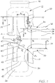
- FIG. 1 and 1A there is illustrated an exemplary pump 10 in accordance with certain embodiments including a pump casing 12, a back liner 14, a front liner 30 and a pump outlet 18.
- An internal chamber 20 is adapted to receive an impeller 40 for rotation about rotational axis X-X.
- the front liner 30 includes a cylindrically-shaped delivery section 32 through which slurry enters the pump chamber 20.
- the delivery section 32 has a passage 33 therein with a first, outermost end 34 operatively connectable to a feed pipe (not shown) and a second, innermost end 35 adjacent the chamber 20.
- the front liner 30 further includes a side wall section 15 which mates with the pump casing 12 to form and enclose the chamber 20, the side wall section 15 having an inner face 37.
- the second end 35 of the front liner 30 has a raised lip 38 thereat, which is arranged to mate with the impeller 40.
- the impeller 40 includes a hub 41 from which a plurality of circumferentially spaced pumping vanes 42 extend. An eye portion 47 extends forwardly from the hub towards the passage 33 in the front liner.
- the pumping vanes 42 include a leading edge 43 located at the region of the impeller inlet, and a trailing edge 44 located at the region of the impeller outlet 49.
- the impeller further includes a front shroud 50 and a back shroud 51, the vanes 42 being disposed therebetween.
- one exemplary pumping vane 42 which extends between the opposing main inner faces of the shrouds 50, 51.
- Normally such an impeller 10A has a plurality of such pumping vanes spaced evenly around the area between the said shrouds 50, 51, for example three, four or five pumping vanes are usual in slurry pumps.
- the exemplary pumping vane 42 is generally arcuate in cross-section and includes an inner leading edge 43 and an outer trailing edge 44 and opposed side faces 45 and 46, the side face 45 being a pumping or pressure side.
- the vanes are normally referred to as backward-curving vanes when viewed with the direction of rotation. Reference numerals identifying the various features described above have only been indicated on the one vanes 42 shown, for the sake of clarity. The important major dimensions of L t , R v and T v have been shown in the Figure and are defined below in this specification.
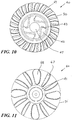
- an exemplary impeller is illustrated in Figs. 3 to 12 .
- the impeller 40 has a plurality of discharge guide vanes (or vanelets).
- the discharge guide vanes are in the form of elongate, flat-topped projections 55 which are generally sausage-shaped in cross-section. These projections 55, extend respectively from the main face of the back shroud 51 and are arranged in between two adjacent pumping vanes 42.
- the projections 55 have a respective outer end 58 which is located adjacent to the outer peripheral edge the shroud 51 on which they are disposed.
- the discharge guide vanes also have an inner end 60, which is located somewhere midway a respective passageway.
- the inner ends 60, of respective discharge guide vanes 55 are spaced some distance from the central rotational axis X-X of the impeller 40.
- the discharge guide vanes can be associated with each passageway.
- Each discharge guide vane in the form of a projection 55 is shown in the drawings with a height of approximately 30-35% of the width of the pumping vane 42 where the width of the pumping vane is defined as the distance between the front and back shrouds of the impeller.
- the guide vane height can be between 5% to 50% of the said pumping vane 42 width.
- Each guide vane is of generally constant height along its length, although in other embodiments the guide vane can be tapered in height and also tapered in width. As is apparent from the drawings, the vanes have bevelled peripheral edges.
- each discharge guide vane can be located closer to the pumping or pressure side face of the closest adjacent pumping vane.
- the positioning of a discharge guide vane closer to one adjacent pumping vane can advantageously improve pump performance.
- the discharge guide vanes can extend for a shorter or longer distance into the discharge passageway than is shown in the embodiments of Figures 3 to 12 , depending on the fluid or slurry to be pumped.
- the discharge guide vanes can be of a different cross-sectional width to the main pumping vanes, and may not even necessarily be elongate, so long as the desired effect on the flow of slurry at the impeller discharge is achieved.
- the discharge guide vanes will reduce the potential for high-velocity vortex type flows to form at low flows. This reduces the potential for particles to wear into the front or rear shrouds thereby resulting in wear cavities in which vortex type flows could originate and develop.
- the guide vanes will also reduce the mixing of the split off flow regions at the immediate exit of the impeller into the already rotating flow pattern in the volute. It is felt that the discharge guide vanes will smooth and reduce the turbulence of the flow from the impeller into the pump casing or volute.
- the impeller 10 further includes expeller, or auxiliary, vanes 67, 68, 69 on respective outer faces of the shrouds. Some of the vanes on the back shroud 67, 68 have different widths. As shown in the Figures, all vanes including the discharge guide vanes have bevelled edges.
- one or more of these parameters have dimensional ratios in the following ranges:
- the ratio R s /D 2 is 0.109; the ratio F r /D 2 is 0.415; the ratio I nr /D 2 is 0.173 and the ration R v /T v is 0.188.
- Both the new and conventional pumps were run at the same duty flow and speed on a gold mining ore.
- the conventional pump impeller life was 1,600 to 1,700 hours and front liner life 700 to 900 hours.
- the new design impeller and front liner life were both 2,138 hours.
- the conventional impeller typically failed by gross wear on the pump vanes and holing of the backshroud.
- the new impeller showed very little of this same type of wear.
- the average life of the conventional impeller and front liner was 4,875 hours with some impeller wear, but typically the front liner failed by holing during use.
- the new impeller and front liner life were in excess of 6,000 hours and without holing.
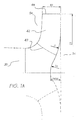
- FIG. 13A Each selected embodiment of an impeller when viewed in cross-section in a plane drawn through the rotational axis has four general profile regions which each have distinct features of shape, as illustrated in Figure 13A .
- Figure 13B is the profile of the features of shape of a particular impeller which have been produced by use of the polynomial.
- X-axis which is a line which extends from the hub of the impeller through the centre of the impeller nose and coaxial with the rotational axis X-X
- actual impeller dimensions are taken and divided by B 2 (the impeller outlet width) to produce a normalised value X n .
Landscapes
- Engineering & Computer Science (AREA)
- Mechanical Engineering (AREA)
- General Engineering & Computer Science (AREA)
- Physics & Mathematics (AREA)
- Fluid Mechanics (AREA)
- Geometry (AREA)
- Structures Of Non-Positive Displacement Pumps (AREA)
- Rotary Pumps (AREA)
- Details And Applications Of Rotary Liquid Pumps (AREA)
- Centrifugal Separators (AREA)
- External Artificial Organs (AREA)
Applications Claiming Priority (4)
| Application Number | Priority Date | Filing Date | Title |
|---|---|---|---|
| AU2008902665A AU2008902665A0 (en) | 2008-05-27 | Improvements relating to centrifugal pumps | |
| AU2009901137A AU2009901137A0 (en) | 2009-03-16 | Improvements relating to centrifugal pumps | |
| PCT/AU2009/000662 WO2009143570A1 (en) | 2008-05-27 | 2009-05-27 | Improvements relating to centrifugal pump impellers |
| EP09753334.3A EP2331826B1 (en) | 2008-05-27 | 2009-05-27 | Improvements relating to centrifugal pump impellers |
Related Parent Applications (2)
| Application Number | Title | Priority Date | Filing Date |
|---|---|---|---|
| EP09753334.3A Division EP2331826B1 (en) | 2008-05-27 | 2009-05-27 | Improvements relating to centrifugal pump impellers |
| EP09753334.3A Division-Into EP2331826B1 (en) | 2008-05-27 | 2009-05-27 | Improvements relating to centrifugal pump impellers |
Publications (2)
| Publication Number | Publication Date |
|---|---|
| EP3009685A1 EP3009685A1 (en) | 2016-04-20 |
| EP3009685B1 true EP3009685B1 (en) | 2020-09-09 |
Family
ID=41376477
Family Applications (2)
| Application Number | Title | Priority Date | Filing Date |
|---|---|---|---|
| EP09753334.3A Active EP2331826B1 (en) | 2008-05-27 | 2009-05-27 | Improvements relating to centrifugal pump impellers |
| EP15196985.4A Active EP3009685B1 (en) | 2008-05-27 | 2009-05-27 | Improvements relating to centrifugal pump impellers |
Family Applications Before (1)
| Application Number | Title | Priority Date | Filing Date |
|---|---|---|---|
| EP09753334.3A Active EP2331826B1 (en) | 2008-05-27 | 2009-05-27 | Improvements relating to centrifugal pump impellers |
Country Status (18)
| Country | Link |
|---|---|
| US (3) | US8608445B2 (ru) |
| EP (2) | EP2331826B1 (ru) |
| CN (4) | CN105508291B (ru) |
| AP (2) | AP2015008293A0 (ru) |
| AR (1) | AR072254A1 (ru) |
| AU (1) | AU2009253737B2 (ru) |
| BR (4) | BR122019021562B1 (ru) |
| CA (3) | CA2911924C (ru) |
| CL (6) | CL2009001301A1 (ru) |
| EA (6) | EA024954B1 (ru) |
| ES (2) | ES2835028T3 (ru) |
| IL (4) | IL209311A (ru) |
| MX (2) | MX339040B (ru) |
| PE (6) | PE20100415A1 (ru) |
| PL (1) | PL2331826T3 (ru) |
| PT (1) | PT3009685T (ru) |
| WO (1) | WO2009143570A1 (ru) |
| ZA (2) | ZA201008492B (ru) |
Families Citing this family (31)
| Publication number | Priority date | Publication date | Assignee | Title |
|---|---|---|---|---|
| US8608445B2 (en) * | 2008-05-27 | 2013-12-17 | Weir Minerals Australia, Ltd. | Centrifugal pump impellers |
| DE102010023931A1 (de) * | 2010-06-16 | 2011-12-22 | Allweiler Ag | Doppelflutige Kreiselpumpe |
| EP2609335B1 (en) | 2010-08-23 | 2019-12-04 | Ecotech Marine, LLC | Pump and pump assembly |
| CN103987956B (zh) * | 2011-10-23 | 2018-06-22 | 安德里兹水利有限公司 | 用于法氏涡轮机转轮的紧凑叶片以及配置转轮的方法 |
| US9488184B2 (en) | 2012-05-02 | 2016-11-08 | King Abdulaziz City For Science And Technology | Method and system of increasing wear resistance of a part of a rotating mechanism exposed to fluid flow therethrough |
| US9309895B2 (en) * | 2012-06-18 | 2016-04-12 | Kennametal Inc. | Closed impeller with a coated vane |
| CN103016398B (zh) * | 2012-12-14 | 2015-06-10 | 清华大学 | 一种控制曲率分布的离心叶轮流道设计方法 |
| CN103644141B (zh) * | 2013-12-20 | 2015-09-30 | 中国农业大学 | 一种获取双吸离心泵叶片载荷分布曲线的方法 |
| RU2688066C2 (ru) * | 2014-04-23 | 2019-05-17 | Зульцер Мэнэджмент Аг | Рабочее колесо для центробежного насоса, центробежный насос, а также его использование |
| WO2016040979A1 (en) * | 2014-09-15 | 2016-03-24 | Weir Minerals Australia Ltd | Slurry pump impeller |
| CA2961066C (en) * | 2014-09-15 | 2022-11-01 | Weir Minerals Australia Ltd | Slurry pump impeller |
| JP6374744B2 (ja) * | 2014-09-26 | 2018-08-15 | 株式会社久保田鉄工所 | インペラを備えたウォーターポンプ |
| CN104279188B (zh) * | 2014-10-29 | 2017-08-01 | 珠海格力电器股份有限公司 | 离心式风机及具有其的空调器 |
| CN104564797B (zh) * | 2015-01-23 | 2017-09-12 | 江苏大学 | 一种固液两相流泵叶轮水力设计方法 |
| GB2542233B (en) | 2015-08-26 | 2018-02-07 | Weir Minerals Europe Ltd | Rotary parts for a slurry pump |
| US9890797B2 (en) * | 2016-06-22 | 2018-02-13 | Ar Impeller, Inc. | Impeller with removable and replaceable vanes for centrifugal pump |
| DE102016112709A1 (de) * | 2016-07-12 | 2018-01-18 | Miele & Cie. Kg | Dichtungsvorrichtung für ein Gebläselaufrad und Gebläse |
| CN106837856B (zh) * | 2017-03-14 | 2023-03-31 | 中交疏浚技术装备国家工程研究中心有限公司 | 高效耐磨挖泥泵三叶片叶轮设计方法及叶轮 |
| JP2018178820A (ja) * | 2017-04-10 | 2018-11-15 | 日本電産サンキョー株式会社 | ポンプ装置 |
| EA202191002A1 (ru) * | 2017-10-12 | 2021-09-09 | Уэйр Минералз Острэйлиа Лтд | Впускной компонент для шламового насоса |
| MA53344A (fr) * | 2018-08-01 | 2021-11-10 | Weir Slurry Group Inc | Agencement d'espace latéral annulaire inversé pour pompe centrifuge |
| CN110159585B (zh) * | 2019-05-23 | 2024-02-13 | 西华大学 | 一种圆盘泵叶轮 |
| JP7396836B2 (ja) * | 2019-09-04 | 2023-12-12 | 古河産機システムズ株式会社 | 渦巻きポンプ組立用冶具および渦巻きポンプの組立方法 |
| CN111005876A (zh) * | 2019-11-22 | 2020-04-14 | 三联泵业股份有限公司 | 一种旋流器给料泵叶轮结构 |
| RU2732082C1 (ru) * | 2020-03-17 | 2020-09-11 | Общество с ограниченной ответственностью «Лизинговая Компания «ЛИАКОН» | Ступень многоступенчатого центробежного насоса |
| WO2022003629A1 (en) * | 2020-07-01 | 2022-01-06 | Padmini Vna Mechatronics Pvt. Ltd. | Electric water pump with improved rotor assembly |
| EP4056851A1 (en) * | 2021-03-09 | 2022-09-14 | Metso Outotec Sweden AB | Wear element for a slurry pump |
| WO2022266725A1 (en) * | 2021-06-25 | 2022-12-29 | Weir Minerals Australia Ltd | Centrifugal pump impeller with tapered shroud |
| KR102399502B1 (ko) * | 2021-12-09 | 2022-05-18 | 주식회사 디지피 | 멀티 타입 임펠러 |
| CN114607636B (zh) * | 2022-02-28 | 2024-02-13 | 江西南方锅炉股份有限公司 | 一种用于锅炉系统的引风机 |
| US11713768B1 (en) * | 2022-06-22 | 2023-08-01 | Robert Bosch Gmbh | Impeller for a centrifugal pump |
Family Cites Families (39)
| Publication number | Priority date | Publication date | Assignee | Title |
|---|---|---|---|---|
| GB1006365A (en) * | 1962-10-15 | 1965-09-29 | English Electric Co Ltd | Improvements in or relating to hydraulic pumps and reversible pump turbines |
| US3167021A (en) * | 1963-04-15 | 1965-01-26 | Allis Chalmers Mfg Co | Nonclogging centrifugal pump |
| US3285187A (en) * | 1965-11-05 | 1966-11-15 | Msl Ind Inc | Impeller for use in centrifugal pump or blower and a method of manufacture thereof |
| US3953150A (en) * | 1972-02-10 | 1976-04-27 | Sundstrand Corporation | Impeller apparatus |
| US3837627A (en) * | 1972-06-07 | 1974-09-24 | Allis Chalmers | Method and apparatus for gasifying a liquid |
| US3881840A (en) * | 1973-09-05 | 1975-05-06 | Neratoom | Centrifugal pump for processing liquids containing abrasive constituents, more particularly, a sand pump or a waste-water pumper |
| CS175720B1 (ru) * | 1974-04-01 | 1977-05-31 | ||
| DE2708368C2 (de) * | 1977-02-26 | 1983-03-24 | Klein, Schanzlin & Becker Ag, 6710 Frankenthal | Laufrad für Kreiselpumpen |
| US4533294A (en) * | 1980-09-25 | 1985-08-06 | Dresser Industries, Inc. | High speed centrifugal pump and method for operating same at reduced noise levels |
| AU7989582A (en) | 1981-01-30 | 1982-08-05 | Baker International Corp. | Centrifugal mud pump |
| US4637779A (en) | 1985-05-17 | 1987-01-20 | Kamyr, Inc. | Two stage medium consistency pulp pumping |
| DE3768495D1 (de) | 1986-10-07 | 1991-04-11 | Warman Int Ltd | Turbine fuer zentrifugalpumpen. |
| US4872809A (en) * | 1987-03-06 | 1989-10-10 | Giw Industries, Inc. | Slurry pump having increased efficiency and wear characteristics |
| DE3820062A1 (de) * | 1988-06-13 | 1989-12-21 | Klein Schanzlin & Becker Ag | Stroemungsmaschine |
| FI87009C (fi) * | 1990-02-21 | 1992-11-10 | Tampella Forest Oy | Skovelhjul foer centrifugalpumpar |
| US5192142A (en) * | 1990-09-27 | 1993-03-09 | Baker Hughes Incorporated | Pump impeller release collar assembly |
| CN1022584C (zh) * | 1990-10-27 | 1993-10-27 | 浙江大学 | 厚叶片离心叶轮 |
| HU217252B (hu) * | 1991-03-22 | 1999-12-28 | Warman International Ltd. | Centrifugál-zagyszivattyú |
| US5192193A (en) * | 1991-06-21 | 1993-03-09 | Ingersoll-Dresser Pump Company | Impeller for centrifugal pumps |
| AU691112B2 (en) * | 1992-12-29 | 1998-05-07 | Vortex Australia Pty. Ltd. | Pump impeller and centrifugal slurry pump incorporating same |
| ATE220177T1 (de) * | 1992-12-29 | 2002-07-15 | Vortex Australia Pty Ltd | Pumpenlaufrad und kreiselpumpe für zähflussige medien mit diesem laufrad |
| TW265395B (ru) * | 1993-03-18 | 1995-12-11 | Warman Int Ltd | |
| DE4336852A1 (de) | 1993-10-28 | 1995-05-04 | Klein Schanzlin & Becker Ag | Leitapparat für Kreiselpumpen |
| RU2061910C1 (ru) | 1993-12-17 | 1996-06-10 | Научно-исследовательское, испытательное и проектное предприятие вентиляторостроения "Турмаш" | Рабочее колесо центробежного вентилятора |
| US5873697A (en) * | 1994-10-11 | 1999-02-23 | Chevron U.S.A., Inc. | Method of improving centrifugal pump efficiency |
| US5605444A (en) * | 1995-12-26 | 1997-02-25 | Ingersoll-Dresser Pump Company | Pump impeller having separate offset inlet vanes |
| RU2120568C1 (ru) | 1996-09-18 | 1998-10-20 | Акционерное общество Научно-исследовательский институт центробежных и роторных компрессоров | Рабочее колесо центробежного компрессора |
| BR0115868B1 (pt) * | 2000-12-04 | 2011-09-20 | conjunto de ventilador centrìfugo, método para fabricação de rotor centrìfugo e método de montagem do conjunto de ventilador centrìfugo. | |
| RU2193692C1 (ru) * | 2001-03-23 | 2002-11-27 | Открытое акционерное общество "Борец" | Ступень скважинного центробежного насоса |
| US20040136825A1 (en) * | 2001-08-08 | 2004-07-15 | Addie Graeme R. | Multiple diverter for reducing wear in a slurry pump |
| ITMI20012413A1 (it) * | 2001-11-15 | 2003-05-15 | Nuovo Pignone Spa | Pala per girante di compressore centrifygo a medio coefficiente di flusso |
| CN2634157Y (zh) * | 2003-04-07 | 2004-08-18 | 王文烈 | 渣浆泵 |
| AU2003903024A0 (en) | 2003-06-16 | 2003-07-03 | Weir Warman Ltd | Improved pump impeller |
| US6988870B2 (en) * | 2004-01-27 | 2006-01-24 | Weir Slurry Group, Inc. | Casing for a centrifugal pump |
| FI20050450A (fi) * | 2005-04-29 | 2006-10-30 | Sulzer Pumpen Ag | Keskipakopumppu ja sen juoksupyörä |
| CA2647689C (en) * | 2006-03-28 | 2015-07-07 | The Gorman-Rupp Company | Impeller |
| CN201053397Y (zh) * | 2007-06-22 | 2008-04-30 | 安徽省天马泵阀集团有限公司 | 纸浆泵 |
| CN101149066B (zh) * | 2007-09-07 | 2012-05-23 | 山东东方天明机械制造有限公司 | 离心式渣浆泵叶轮调整间隙区冲刷降蚀工艺及其设备 |
| US8608445B2 (en) * | 2008-05-27 | 2013-12-17 | Weir Minerals Australia, Ltd. | Centrifugal pump impellers |
-
2009
- 2009-05-27 US US12/736,934 patent/US8608445B2/en active Active
- 2009-05-27 AP AP2015008293A patent/AP2015008293A0/xx unknown
- 2009-05-27 EA EA201400072A patent/EA024954B1/ru not_active IP Right Cessation
- 2009-05-27 BR BR122019021562-6A patent/BR122019021562B1/pt active IP Right Grant
- 2009-05-27 CN CN201510940218.XA patent/CN105508291B/zh active Active
- 2009-05-27 EA EA201400071A patent/EA025854B1/ru not_active IP Right Cessation
- 2009-05-27 EP EP09753334.3A patent/EP2331826B1/en active Active
- 2009-05-27 PE PE2009000738A patent/PE20100415A1/es active IP Right Grant
- 2009-05-27 BR BR122019021556-1A patent/BR122019021556B1/pt active IP Right Grant
- 2009-05-27 BR BRPI0909600A patent/BRPI0909600B1/pt active IP Right Grant
- 2009-05-27 CN CN201310273131.2A patent/CN103343752B/zh not_active Expired - Fee Related
- 2009-05-27 EA EA201071360A patent/EA022592B9/ru not_active IP Right Cessation
- 2009-05-27 PL PL09753334T patent/PL2331826T3/pl unknown
- 2009-05-27 AR ARP090101897 patent/AR072254A1/es active IP Right Grant
- 2009-05-27 CA CA2911924A patent/CA2911924C/en active Active
- 2009-05-27 MX MX2010013007A patent/MX339040B/es active IP Right Grant
- 2009-05-27 PE PE2014000045A patent/PE20141833A1/es not_active Application Discontinuation
- 2009-05-27 AU AU2009253737A patent/AU2009253737B2/en active Active
- 2009-05-27 CN CN201811137912.8A patent/CN109340123B/zh active Active
- 2009-05-27 CN CN200980128248.3A patent/CN102099585B/zh active Active
- 2009-05-27 PE PE2014000042A patent/PE20141846A1/es active IP Right Grant
- 2009-05-27 ES ES15196985T patent/ES2835028T3/es active Active
- 2009-05-27 PT PT151969854T patent/PT3009685T/pt unknown
- 2009-05-27 PE PE2014000043A patent/PE20141829A1/es active IP Right Grant
- 2009-05-27 WO PCT/AU2009/000662 patent/WO2009143570A1/en active Application Filing
- 2009-05-27 CA CA2911931A patent/CA2911931C/en not_active Expired - Fee Related
- 2009-05-27 BR BR122019021566-9A patent/BR122019021566B1/pt active IP Right Grant
- 2009-05-27 AP AP2010005475A patent/AP3376A/xx active
- 2009-05-27 ES ES09753334.3T patent/ES2567733T3/es active Active
- 2009-05-27 EA EA201400073A patent/EA024868B1/ru not_active IP Right Cessation
- 2009-05-27 EA EA201400075A patent/EA024898B1/ru not_active IP Right Cessation
- 2009-05-27 EA EA201400074A patent/EA024932B1/ru not_active IP Right Cessation
- 2009-05-27 PE PE2014000044A patent/PE20141832A1/es active IP Right Grant
- 2009-05-27 PE PE2014000046A patent/PE20141834A1/es not_active Application Discontinuation
- 2009-05-27 CL CL2009001301A patent/CL2009001301A1/es unknown
- 2009-05-27 CA CA2725539A patent/CA2725539C/en active Active
- 2009-05-27 EP EP15196985.4A patent/EP3009685B1/en active Active
-
2010
- 2010-11-15 IL IL20931110A patent/IL209311A/en active IP Right Grant
- 2010-11-25 ZA ZA2010/08492A patent/ZA201008492B/en unknown
- 2010-11-26 MX MX2020009897A patent/MX2020009897A/es unknown
-
2012
- 2012-03-15 CL CL2012000663A patent/CL2012000663A1/es unknown
-
2013
- 2013-09-17 IL IL228480A patent/IL228480A/en active IP Right Grant
- 2013-09-17 IL IL22848113A patent/IL228481A/en active IP Right Grant
- 2013-09-17 IL IL228482A patent/IL228482A/en active IP Right Grant
- 2013-12-13 US US14/106,405 patent/US9004869B2/en active Active
-
2015
- 2015-04-10 US US14/683,686 patent/US9422938B2/en active Active
-
2016
- 2016-09-27 CL CL2016002428A patent/CL2016002428A1/es unknown
- 2016-09-27 CL CL2016002425A patent/CL2016002425A1/es unknown
- 2016-09-27 CL CL2016002427A patent/CL2016002427A1/es unknown
- 2016-09-27 CL CL2016002426A patent/CL2016002426A1/es unknown
-
2018
- 2018-10-11 ZA ZA2018/06758A patent/ZA201806758B/en unknown
Non-Patent Citations (1)
| Title |
|---|
| None * |
Also Published As
Similar Documents
| Publication | Publication Date | Title |
|---|---|---|
| EP3009685B1 (en) | Improvements relating to centrifugal pump impellers | |
| EP2978975B1 (en) | Slurry pump impeller | |
| US20140044545A1 (en) | Slurry pump impeller | |
| AU2013202462B2 (en) | Improvements relating to centrifugal pump impellers | |
| EP2734736B1 (en) | Improvements to pumps and components therefor |
Legal Events
| Date | Code | Title | Description |
|---|---|---|---|
| PUAI | Public reference made under article 153(3) epc to a published international application that has entered the european phase |
Free format text: ORIGINAL CODE: 0009012 |
|
| AC | Divisional application: reference to earlier application |
Ref document number: 2331826 Country of ref document: EP Kind code of ref document: P |
|
| AK | Designated contracting states |
Kind code of ref document: A1 Designated state(s): AT BE BG CH CY CZ DE DK EE ES FI FR GB GR HR HU IE IS IT LI LT LU LV MC MK MT NL NO PL PT RO SE SI SK TR |
|
| 17P | Request for examination filed |
Effective date: 20160923 |
|
| RBV | Designated contracting states (corrected) |
Designated state(s): AT BE BG CH CY CZ DE DK EE ES FI FR GB GR HR HU IE IS IT LI LT LU LV MC MK MT NL NO PL PT RO SE SI SK TR |
|
| STAA | Information on the status of an ep patent application or granted ep patent |
Free format text: STATUS: EXAMINATION IS IN PROGRESS |
|
| 17Q | First examination report despatched |
Effective date: 20190729 |
|
| GRAP | Despatch of communication of intention to grant a patent |
Free format text: ORIGINAL CODE: EPIDOSNIGR1 |
|
| STAA | Information on the status of an ep patent application or granted ep patent |
Free format text: STATUS: GRANT OF PATENT IS INTENDED |
|
| INTG | Intention to grant announced |
Effective date: 20200424 |
|
| GRAS | Grant fee paid |
Free format text: ORIGINAL CODE: EPIDOSNIGR3 |
|
| GRAA | (expected) grant |
Free format text: ORIGINAL CODE: 0009210 |
|
| STAA | Information on the status of an ep patent application or granted ep patent |
Free format text: STATUS: THE PATENT HAS BEEN GRANTED |
|
| AC | Divisional application: reference to earlier application |
Ref document number: 2331826 Country of ref document: EP Kind code of ref document: P |
|
| AK | Designated contracting states |
Kind code of ref document: B1 Designated state(s): AT BE BG CH CY CZ DE DK EE ES FI FR GB GR HR HU IE IS IT LI LT LU LV MC MK MT NL NO PL PT RO SE SI SK TR |
|
| REG | Reference to a national code |
Ref country code: GB Ref legal event code: FG4D |
|
| REG | Reference to a national code |
Ref country code: AT Ref legal event code: REF Ref document number: 1311924 Country of ref document: AT Kind code of ref document: T Effective date: 20200915 Ref country code: CH Ref legal event code: EP |
|
| REG | Reference to a national code |
Ref country code: DE Ref legal event code: R096 Ref document number: 602009062761 Country of ref document: DE |
|
| REG | Reference to a national code |
Ref country code: IE Ref legal event code: FG4D |
|
| REG | Reference to a national code |
Ref country code: RO Ref legal event code: EPE |
|
| REG | Reference to a national code |
Ref country code: FI Ref legal event code: FGE |
|
| REG | Reference to a national code |
Ref country code: SE Ref legal event code: TRGR |
|
| REG | Reference to a national code |
Ref country code: NL Ref legal event code: FP |
|
| REG | Reference to a national code |
Ref country code: PT Ref legal event code: SC4A Ref document number: 3009685 Country of ref document: PT Date of ref document: 20210121 Kind code of ref document: T Free format text: AVAILABILITY OF NATIONAL TRANSLATION Effective date: 20210111 |
|
| REG | Reference to a national code |
Ref country code: LT Ref legal event code: MG4D |
|
| PG25 | Lapsed in a contracting state [announced via postgrant information from national office to epo] |
Ref country code: HR Free format text: LAPSE BECAUSE OF FAILURE TO SUBMIT A TRANSLATION OF THE DESCRIPTION OR TO PAY THE FEE WITHIN THE PRESCRIBED TIME-LIMIT Effective date: 20200909 Ref country code: LT Free format text: LAPSE BECAUSE OF FAILURE TO SUBMIT A TRANSLATION OF THE DESCRIPTION OR TO PAY THE FEE WITHIN THE PRESCRIBED TIME-LIMIT Effective date: 20200909 Ref country code: NO Free format text: LAPSE BECAUSE OF FAILURE TO SUBMIT A TRANSLATION OF THE DESCRIPTION OR TO PAY THE FEE WITHIN THE PRESCRIBED TIME-LIMIT Effective date: 20201209 |
|
| REG | Reference to a national code |
Ref country code: AT Ref legal event code: MK05 Ref document number: 1311924 Country of ref document: AT Kind code of ref document: T Effective date: 20200909 |
|
| PG25 | Lapsed in a contracting state [announced via postgrant information from national office to epo] |
Ref country code: LV Free format text: LAPSE BECAUSE OF FAILURE TO SUBMIT A TRANSLATION OF THE DESCRIPTION OR TO PAY THE FEE WITHIN THE PRESCRIBED TIME-LIMIT Effective date: 20200909 |
|
| PG25 | Lapsed in a contracting state [announced via postgrant information from national office to epo] |
Ref country code: EE Free format text: LAPSE BECAUSE OF FAILURE TO SUBMIT A TRANSLATION OF THE DESCRIPTION OR TO PAY THE FEE WITHIN THE PRESCRIBED TIME-LIMIT Effective date: 20200909 |
|
| PG25 | Lapsed in a contracting state [announced via postgrant information from national office to epo] |
Ref country code: IS Free format text: LAPSE BECAUSE OF FAILURE TO SUBMIT A TRANSLATION OF THE DESCRIPTION OR TO PAY THE FEE WITHIN THE PRESCRIBED TIME-LIMIT Effective date: 20210109 Ref country code: AT Free format text: LAPSE BECAUSE OF FAILURE TO SUBMIT A TRANSLATION OF THE DESCRIPTION OR TO PAY THE FEE WITHIN THE PRESCRIBED TIME-LIMIT Effective date: 20200909 |
|
| REG | Reference to a national code |
Ref country code: DE Ref legal event code: R097 Ref document number: 602009062761 Country of ref document: DE |
|
| REG | Reference to a national code |
Ref country code: ES Ref legal event code: FG2A Ref document number: 2835028 Country of ref document: ES Kind code of ref document: T3 Effective date: 20210621 |
|
| PG25 | Lapsed in a contracting state [announced via postgrant information from national office to epo] |
Ref country code: SK Free format text: LAPSE BECAUSE OF FAILURE TO SUBMIT A TRANSLATION OF THE DESCRIPTION OR TO PAY THE FEE WITHIN THE PRESCRIBED TIME-LIMIT Effective date: 20200909 |
|
| PLBE | No opposition filed within time limit |
Free format text: ORIGINAL CODE: 0009261 |
|
| STAA | Information on the status of an ep patent application or granted ep patent |
Free format text: STATUS: NO OPPOSITION FILED WITHIN TIME LIMIT |
|
| 26N | No opposition filed |
Effective date: 20210610 |
|
| PG25 | Lapsed in a contracting state [announced via postgrant information from national office to epo] |
Ref country code: SI Free format text: LAPSE BECAUSE OF FAILURE TO SUBMIT A TRANSLATION OF THE DESCRIPTION OR TO PAY THE FEE WITHIN THE PRESCRIBED TIME-LIMIT Effective date: 20200909 Ref country code: DK Free format text: LAPSE BECAUSE OF FAILURE TO SUBMIT A TRANSLATION OF THE DESCRIPTION OR TO PAY THE FEE WITHIN THE PRESCRIBED TIME-LIMIT Effective date: 20200909 |
|
| REG | Reference to a national code |
Ref country code: CH Ref legal event code: PL |
|
| PG25 | Lapsed in a contracting state [announced via postgrant information from national office to epo] |
Ref country code: CH Free format text: LAPSE BECAUSE OF NON-PAYMENT OF DUE FEES Effective date: 20210531 Ref country code: MC Free format text: LAPSE BECAUSE OF FAILURE TO SUBMIT A TRANSLATION OF THE DESCRIPTION OR TO PAY THE FEE WITHIN THE PRESCRIBED TIME-LIMIT Effective date: 20200909 Ref country code: LI Free format text: LAPSE BECAUSE OF NON-PAYMENT OF DUE FEES Effective date: 20210531 Ref country code: LU Free format text: LAPSE BECAUSE OF NON-PAYMENT OF DUE FEES Effective date: 20210527 |
|
| PGFP | Annual fee paid to national office [announced via postgrant information from national office to epo] |
Ref country code: NL Payment date: 20220526 Year of fee payment: 14 |
|
| PGFP | Annual fee paid to national office [announced via postgrant information from national office to epo] |
Ref country code: RO Payment date: 20220509 Year of fee payment: 14 Ref country code: CZ Payment date: 20220510 Year of fee payment: 14 Ref country code: BG Payment date: 20220530 Year of fee payment: 14 |
|
| PG25 | Lapsed in a contracting state [announced via postgrant information from national office to epo] |
Ref country code: HU Free format text: LAPSE BECAUSE OF FAILURE TO SUBMIT A TRANSLATION OF THE DESCRIPTION OR TO PAY THE FEE WITHIN THE PRESCRIBED TIME-LIMIT; INVALID AB INITIO Effective date: 20090527 Ref country code: CY Free format text: LAPSE BECAUSE OF FAILURE TO SUBMIT A TRANSLATION OF THE DESCRIPTION OR TO PAY THE FEE WITHIN THE PRESCRIBED TIME-LIMIT Effective date: 20200909 |
|
| PGFP | Annual fee paid to national office [announced via postgrant information from national office to epo] |
Ref country code: DE Payment date: 20230530 Year of fee payment: 15 |
|
| REG | Reference to a national code |
Ref country code: NL Ref legal event code: MM Effective date: 20230601 |
|
| PG25 | Lapsed in a contracting state [announced via postgrant information from national office to epo] |
Ref country code: RO Free format text: LAPSE BECAUSE OF NON-PAYMENT OF DUE FEES Effective date: 20230527 Ref country code: CZ Free format text: LAPSE BECAUSE OF NON-PAYMENT OF DUE FEES Effective date: 20230527 |
|
| PG25 | Lapsed in a contracting state [announced via postgrant information from national office to epo] |
Ref country code: NL Free format text: LAPSE BECAUSE OF NON-PAYMENT OF DUE FEES Effective date: 20230601 |
|
| PG25 | Lapsed in a contracting state [announced via postgrant information from national office to epo] |
Ref country code: MK Free format text: LAPSE BECAUSE OF FAILURE TO SUBMIT A TRANSLATION OF THE DESCRIPTION OR TO PAY THE FEE WITHIN THE PRESCRIBED TIME-LIMIT Effective date: 20200909 |
|
| PGFP | Annual fee paid to national office [announced via postgrant information from national office to epo] |
Ref country code: IE Payment date: 20240527 Year of fee payment: 16 |
|
| PGFP | Annual fee paid to national office [announced via postgrant information from national office to epo] |
Ref country code: GB Payment date: 20240527 Year of fee payment: 16 |
|
| PGFP | Annual fee paid to national office [announced via postgrant information from national office to epo] |
Ref country code: GR Payment date: 20240529 Year of fee payment: 16 |
|
| PGFP | Annual fee paid to national office [announced via postgrant information from national office to epo] |
Ref country code: ES Payment date: 20240603 Year of fee payment: 16 |
|
| PGFP | Annual fee paid to national office [announced via postgrant information from national office to epo] |
Ref country code: FR Payment date: 20240527 Year of fee payment: 16 Ref country code: FI Payment date: 20240527 Year of fee payment: 16 |
|
| PGFP | Annual fee paid to national office [announced via postgrant information from national office to epo] |
Ref country code: PL Payment date: 20240520 Year of fee payment: 16 Ref country code: PT Payment date: 20240507 Year of fee payment: 16 |
|
| PGFP | Annual fee paid to national office [announced via postgrant information from national office to epo] |
Ref country code: TR Payment date: 20240507 Year of fee payment: 16 Ref country code: SE Payment date: 20240527 Year of fee payment: 16 Ref country code: BE Payment date: 20240527 Year of fee payment: 16 |
|
| PG25 | Lapsed in a contracting state [announced via postgrant information from national office to epo] |
Ref country code: MT Free format text: LAPSE BECAUSE OF FAILURE TO SUBMIT A TRANSLATION OF THE DESCRIPTION OR TO PAY THE FEE WITHIN THE PRESCRIBED TIME-LIMIT Effective date: 20200909 |
|
| PGFP | Annual fee paid to national office [announced via postgrant information from national office to epo] |
Ref country code: IT Payment date: 20240521 Year of fee payment: 16 |