EP3009680A1 - Mehrstufige Kreiselpumpe - Google Patents
Mehrstufige Kreiselpumpe Download PDFInfo
- Publication number
- EP3009680A1 EP3009680A1 EP14188999.8A EP14188999A EP3009680A1 EP 3009680 A1 EP3009680 A1 EP 3009680A1 EP 14188999 A EP14188999 A EP 14188999A EP 3009680 A1 EP3009680 A1 EP 3009680A1
- Authority
- EP
- European Patent Office
- Prior art keywords
- centrifugal pump
- clamping bolt
- pump according
- ring
- clamping
- Prior art date
- Legal status (The legal status is an assumption and is not a legal conclusion. Google has not performed a legal analysis and makes no representation as to the accuracy of the status listed.)
- Granted
Links
Images




Classifications
-
- F—MECHANICAL ENGINEERING; LIGHTING; HEATING; WEAPONS; BLASTING
- F04—POSITIVE - DISPLACEMENT MACHINES FOR LIQUIDS; PUMPS FOR LIQUIDS OR ELASTIC FLUIDS
- F04D—NON-POSITIVE-DISPLACEMENT PUMPS
- F04D17/00—Radial-flow pumps, e.g. centrifugal pumps; Helico-centrifugal pumps
- F04D17/08—Centrifugal pumps
- F04D17/10—Centrifugal pumps for compressing or evacuating
- F04D17/12—Multi-stage pumps
-
- F—MECHANICAL ENGINEERING; LIGHTING; HEATING; WEAPONS; BLASTING
- F04—POSITIVE - DISPLACEMENT MACHINES FOR LIQUIDS; PUMPS FOR LIQUIDS OR ELASTIC FLUIDS
- F04D—NON-POSITIVE-DISPLACEMENT PUMPS
- F04D1/00—Radial-flow pumps, e.g. centrifugal pumps; Helico-centrifugal pumps
- F04D1/06—Multi-stage pumps
- F04D1/063—Multi-stage pumps of the vertically split casing type
-
- F—MECHANICAL ENGINEERING; LIGHTING; HEATING; WEAPONS; BLASTING
- F04—POSITIVE - DISPLACEMENT MACHINES FOR LIQUIDS; PUMPS FOR LIQUIDS OR ELASTIC FLUIDS
- F04D—NON-POSITIVE-DISPLACEMENT PUMPS
- F04D13/00—Pumping installations or systems
- F04D13/02—Units comprising pumps and their driving means
- F04D13/021—Units comprising pumps and their driving means containing a coupling
-
- F—MECHANICAL ENGINEERING; LIGHTING; HEATING; WEAPONS; BLASTING
- F04—POSITIVE - DISPLACEMENT MACHINES FOR LIQUIDS; PUMPS FOR LIQUIDS OR ELASTIC FLUIDS
- F04D—NON-POSITIVE-DISPLACEMENT PUMPS
- F04D29/00—Details, component parts, or accessories
- F04D29/40—Casings; Connections of working fluid
- F04D29/42—Casings; Connections of working fluid for radial or helico-centrifugal pumps
- F04D29/426—Casings; Connections of working fluid for radial or helico-centrifugal pumps especially adapted for liquid pumps
-
- F—MECHANICAL ENGINEERING; LIGHTING; HEATING; WEAPONS; BLASTING
- F04—POSITIVE - DISPLACEMENT MACHINES FOR LIQUIDS; PUMPS FOR LIQUIDS OR ELASTIC FLUIDS
- F04D—NON-POSITIVE-DISPLACEMENT PUMPS
- F04D29/00—Details, component parts, or accessories
- F04D29/60—Mounting; Assembling; Disassembling
- F04D29/62—Mounting; Assembling; Disassembling of radial or helico-centrifugal pumps
- F04D29/628—Mounting; Assembling; Disassembling of radial or helico-centrifugal pumps especially adapted for liquid pumps
Definitions
- the invention relates to a multi-stage centrifugal pump with the features specified in the preamble of claim 1.
- the invention is based on a prior art, as it is known for example by the Grundfos pump series CR and CRE.
- These pumps are multi-stage, vertically operated centrifugal pumps, with a foot part and with a head part, between which at least two pump stages are arranged, each having an impeller and a surrounding housing.
- the suction and the pressure connection of the pump are formed in the foot part.
- the liquid to be delivered passes through a suction nozzle, which is also located in the foot of the pump, first in the first and further to the last pump stage, where he returned to the foot part via an annular channel formed between the outer shell and the housings and out there via a suction nozzle out of the pump.
- the drive shaft connecting the impellers of the pump is led out sealingly through the head part, where a motor chair connects, which is provided for receiving an electric drive motor, and in which the pump-side shaft of the motor-side shaft is motion-coupled.
- a motor chair connects, which is provided for receiving an electric drive motor, and in which the pump-side shaft of the motor-side shaft is motion-coupled.
- head and foot are typically formed of a metallic casting material
- the outer shell consists of a cylinder-shaped sheet metal.
- the outer shell and the pump stages are clamped between the head and foot and are held by four clamping bolts, which are guided by holes in the cylinder body laterally projecting corners of the head and foot.
- the voltage conditions within the pump may change undesirably, since the clamping bolts undergo a different thermal expansion than the housing of the pump stages.
- the clamping bolts By arranged with a small distance to the housing shell clamping bolts, objects or flying parts can jam or at least deposit in this area, which is undesirable.
- These clamping bolts also disturb the overall visual impression of the pump, which is, moreover, characterized by the simple cylinder jacket, which is usually made of stainless steel.
- a panel of the clamping bolt is expensive and expensive.
- US 2,957,426 is a multi-stage pump to the prior art, in which the pump stages can be connected either in parallel or in series.
- the individual pump stages are connected there via studs, which run partly through the pressure channel and connect the pump stages with an end portion of the pump housing, which surrounds all pump stages circumferentially and at one end face with distance.
- the present invention has the object, a generic multi-stage centrifugal pump in such a way that the aforementioned disadvantages avoided, at least reduced.
- the multi-stage centrifugal pump according to the invention has a foot part and a head part, between which at least two pump stages are arranged, each having an impeller and a housing surrounding this. These housings are surrounded at a distance by an outer jacket, so that an annular channel is formed, wherein clamping bolts are provided, which connect the head part and the foot part, including the jacket and the housings. According to the invention, the clamping bolts are arranged in the annular channel between the outer shell and the housings.
- the basic idea of the present invention is thus to guide the clamping bolts, which clamp the pump stages between the head part and the foot part and the outer casing between the head part and the foot part, not on the outside of the outer casing, but inside the outer casing, in which through the housing To arrange pump stages and the outer shell formed annular channel.
- the arrangement according to the invention has numerous advantages. In addition to the visually appealing appearance of the pump is hidden by the outer shell arranged clamping bolt prevents accumulate here objects or even jammed.
- An essential technical advantage is that it is ensured by the arrangement of the clamping bolt in the annular channel, ie where flow of liquid flows along, that clamping bolt, outer skin and pump stage always the same temperature level, namely that of the pumped liquid have.
- This is particularly advantageous if, on the one hand, delivery fluids are conveyed with a strongly fluctuating temperature level and, on the other hand, the temperature of the delivery fluid deviates greatly from the ambient temperature of the pump. Due to the arrangement of the clamping bolts within the conveying fluid flow is achieved that the thermal expansion of the clamping bolt on the one hand and the pump stages on the other hand always done substantially the same, so that no temperature-induced load peaks can occur here. It is to be assumed that both the pump stages, but at least the housing and the clamping bolts, typically also the outer skin, consist of similar materials, typically metal, which have a substantially equal expansion coefficient.
- the arranged inside the annular channel studs form a kind of guide for the pumped liquid, so that at least when the annular channel is flowed through the pressure side, a significantly lower turbulence of the liquid occurs at the discharge nozzle, as compared to comparable conventional pump the case is.
- the pressure-effective surface is reduced to the head part or the foot part to the cross-sectional area of the clamping bolt by the inwardly laying the clamping bolt.
- the annular channel is connected so that it fluidly connects the pressure-side outlet preferably the last pump stage with the pressure port of the pump, as is the case with the pump series according to the prior art mentioned above.
- the above-mentioned advantages arise fluidically, in addition, the pressure-effective surfaces within the pump housing and thus the effective forces are reduced by the clamping bolt.
- the centrifugal pump according to the invention may also be constructed such that the annular channel is provided on the suction connection side, that is, connects a suction connection of the pump with a suction inlet, preferably in a fluid-conducting manner, to the first pump stage.
- the pressure load, in particular of the outer shell is significantly lower than in the other variant.
- clamping bolts are provided, which are arranged at the same angular distance in the annular channel. This provides a minimum of uniformity in terms of force application.
- four clamping bolts are provided in the solution according to the invention, which are arranged at a spacing of 90 ° angle relative to the impeller axis uniformly distributed in the annular channel. This arrangement is particularly advantageous both in terms of power distribution and in terms of flow guidance.
- the clamping bolts are provided at least one end, but preferably at both ends with an external thread, so that they can be clamped either on both sides by means of nuts, which are supported on the headboard or footboard.
- headboard or frequentlyteil crystal holes can be provided which are provided with an internal thread, in which then one end of a clamping bolt can be screwed, so that attachment by means of the mother takes place only at the other end.
- the bores are preferably designed as through holes, so that no corrosion-promoting liquid can collect in the bore.
- a blind hole may also be provided, which near the end has an outwardly leading channel, for example in the form of a transverse bore, in order to be able to discharge this corrosive fluid to the outside if necessary.
- one end of a clamping bolt can also be formed via other positive locking means, for example in the form of a hook or a radially widened cylindrical shoulder, which engages in a corresponding receptacle on the inside of the foot or head part. If, for example, a hook is provided at the end of a clamping bolt, then a web is provided on the foot or headboard side into which it can be hooked. Also, a suitable other positive connection can be provided.
- sealant provide between clamping bolt and headboard and / or footboard.
- Such sealing means are to be provided when the clamping bolt or a component connected thereto passes through the head part or the foot part. According to the invention, a variety of solutions for sealing this area are provided, which are described in detail below.
- a good and cost-effective sealing results when a seal between the clamping bolt and through hole is arranged and the clamping bolt is formed thread-free in the region of this seal.
- This can advantageously serve an O-ring seal, this is inexpensive and reliable.
- the O-ring sealingly full circumference abut, so a seal is here much more effective and easier than in the area of the thread.
- Through hole here is also a smooth cylindrical wall, for example, paragraphs, grooves or other aids may be provided to hold the seal, in particular the O-ring at the intended location also here.
- a groove-like seal seat provided according to an embodiment of the invention clamping bolt side, which has a first contact shoulder, which is formed by a ring in a groove is fixed to the clamping bolt and having a second abutment shoulder, which is formed by a further ring having an internal thread and which is fixed on a threaded portion of the clamping bolt.
- the arrangement is expediently such that it is a threaded portion of the thread, with which the clamping bolt is fixed and clamped on the housing side, that is typically at a portion of the provided at one end external thread.
- the fixation of the clamping bolt on the head or foot can be done by means of a cap nut, on the one hand has a through hole radially superior collar with which it can be supported beyond the through hole on the head or foot.
- the cap nut on a hollow cylindrical portion which engages in the through hole, has on its outer circumference a circumferential groove as a seal seat for the O-ring and is provided with an internal thread, in which engages the thread at the end of the tie rod.
- a seal seat for an O-ring may be formed by an internally threaded ring fixed on a threaded portion of the clamp bolt. Through hole side is then advantageously provided a circumferential groove, in which the O-ring is held in a form-fitting manner to rest with its inside on the sealing seat formed by the ring. It does not necessarily have a groove provided, it is also conceivable that near the end of the through hole a shoulder is provided, in which the O-ring is received. Then, the seal seat, so the receptacle for the O-ring, are formed by this stepped widened part of the through hole in conjunction with a covering annular disc, wherein the annular disc, which otherwise replaces the third wall formed by the groove in the through hole.
- the clamping bolts are inside, so where they are not visible to the user, a modular construction is conceivable, for example, from clamping bolt sections which provided at one end with a bore provided with an internal thread and at the other end with an external thread are, which is thus suitable for the extension of a clamping bolt. That way you can for series of pumps of different number of stages identical clamping bolts are used, which are brought by one or more suitable extensions to the required length. Thus, the same clamping bolts can be used in pumps with different head parts, with a required adjustment is made by such an extension part.
- the ratio of the pressure acting on the clamping bolt surfaces, which are loaded with the output pressure of the pump and the input pressure of the pump at least two, preferably between three and five.
- This area ratio is particularly advantageous because then the internal arrangement of the clamping bolt has virtually no noticeable effect on the output pressure of the pump, so that the output pressure of the pump corresponds approximately to that produced by a comparable pump with externally arranged clamping bolt with the same drive power.
- the pump has a foot part 1 on which the pump is operated.
- the foot part 1 has a connecting flange 2, which forms the suction nozzle of the pump and which surrounds a suction channel 3, which opens within a suction chamber formed in the foot part 1, to which the suction mouth of a rotary impeller 4 of a first pump stage connects, through the impeller 4 and a surrounding housing 5 is formed.
- a connecting flange 2 which forms the suction nozzle of the pump and which surrounds a suction channel 3 which opens within a suction chamber formed in the foot part 1, to which the suction mouth of a rotary impeller 4 of a first pump stage connects, through the impeller 4 and a surrounding housing 5 is formed.
- a total of five stages each consisting of a rotary impeller 4 and a housing 5 are arranged vertically one above the other, the rotary wheels 4 sitting on a common shaft 6 which is rotatably mounted within the pump housing and at the top, namely in the region of the head part 7, is led out of this.
- the housing 5 are cylindrical on its outer side and arranged sealingly against each other. They limit an annular channel 8 on the inside, which is bounded on the outside by an outer jacket 9, which consists of sheet metal and forms part of the pump housing. Outer jacket 9 and the housing 5 are clamped between the foot part 1 and the head part 7, the clamping forces required for this purpose are distributed by four at the same angular distance about the longitudinal axis 10 of the pump, which also forms the axis of rotation 10 of the shaft 6, arranged tie rods in the form of clamping bolts 11th held.
- Each clamping bolt 11 is provided at its two ends with an external thread which is screwed in an internally threaded bore 12 on the foot part 1 with one end. The other end is in the execution after Fig. 2 passed through a through hole 13 in the head part 7 and clamped there by means of a nut 14.
- FIG. 2 This on the basis of Fig. 2 shown construction principle can be varied both in terms of relieveteil paragraphen attachment and in terms of the headboard side attachment, as already mentioned in the introduction. As far as the headboard side attachment is concerned, appropriate alternatives based on the Fig. 3 - 11 shown, which are also suitable for a foot-side attachment in principle.
- the four clamping bolts 11 are arranged not only at the same angular distance of 90 ° about the longitudinal axis 10 distributed in the annular channel 8, but also radially centered in the channel 8, so that they the same distance to the outside of the housing 5 and the inside of the outer jacket. 9 exhibit.
- This annular channel 8 opens within the foot part 1 in a pressure channel 15, which leads to a pressure port 16, the connection flange in the Fig. 1 and 2 is visible.
- the head portion 7 of the pump is extended upwards and there formed in a conventional manner to a motor chair 17, which is provided for attachment of the coming to rest electric drive motor whose shaft via a coupling, not shown here with the free end of the shaft 6 is rotatably connected.
- the clamping bolts 11 are defined in through holes 13 of the head part, they must be sealed against the head part to ensure the tightness of the housing in this area.
- the headboard side threaded end 18 of the clamping bolt 11 is not enough through the through hole 13 therethrough, but only into this.
- Recorded is the threaded end 18 of the clamping bolt 11 in a cap nut 19, as this is based on the Fig. 4 is shown in detail.
- This cap nut 19 has a head 20, which has both a hexagon socket and an external hexagon for receiving a tool in the illustrated embodiment, and is sized so that it projects beyond the through hole 13 radially.
- This radially projecting head rests on a washer 21 in the mounted state on the correspondingly above the through hole 13 formed in the head part 7 screw head support surface 22.
- the cap nut 19 From the head 20 on the cap nut 19 is cylindrical, with a circumferential groove 23 is provided at a short distance behind the head, which serves to receive an O-ring 24 which is held within this groove 23 and the cap nut 19 within the through hole 13 in the head part 7 seals.
- the cap nut is formed as a hollow cylinder and has an internal thread 25, in which the threaded end 18 of the clamping bolt 11 engages. With this cap nut 19, the clamping bolt 11, which is fixed with its other end in the foot part 1, clamped and sealed against the through hole 13 by means of the seal in the form of the O-ring 24.
- a headboard-side attachment of the clamping bolt 11 is shown by means of a cap nut 26, which differs from the above-described cap nut 19 in that the washer 21 provided there may be omitted by appropriate design of the annular surface below the head and the head support surface.
- the head part 7 is shown there only in the region of the through hole, since in this illustration only the attachment and sealing is to be shown.
- the through hole 13 is flared toward the interior of the pump housing, this flared portion is denoted by 27 and joins the interior of the pump housing to the cylindrical part of the through hole 13, at which the lying in the groove 23 of the cap nut 26 O-ring 24 sealingly is applied.
- a transverse bore 28 provided, which passes through the cap nut 26 transversely and the one hand in the internally threaded blind hole of the cap nut 26 and on the other hand in the flared portion 27 of the through hole 13 opens, so as to ensure that within the cap nut 26 no dead space is formed in the can accumulate corrosive fluid. So that this transverse bore 28 is not enclosed by the threaded portion 18 of the clamping bolt 11, in this embodiment, the clamping bolt 11 is provided in the region between its shaft and the threaded end 18 with a circumferential bead 29, which is too wide screwing into the internal thread 25th the cap nut prevents.
- the clamping bolt 11 passes through the through hole 13 completely and is there fixed at its threaded end 18 by means of the nut 14 with the inclusion of a washer 21 in the head part 7.
- the through hole 13 is formed offset, so that in this area, a clearance between the clamping bolt 11 and the through hole 13 is formed, which allows the incorporation of the sealing ring in the form of the O-ring 24.
- rings 30 and 31 are provided for holding the O-ring 24 in its intended position, which are clamped on the clamping bolt 11 and receive the O-ring 24. These rings can be positively or materially seated on the clamping bolt 11. It may be the ring 30 is provided with an internal thread, which then opposite Fig. 7 longer running thread on section 18 from the center can be screwed, the Ring 31 may be fixed via a groove in the clamping bolt 11.
- the rings 30 and 31 may be formed in two parts and clip-fastened, they may be made of plastic, since they are only slightly loaded in terms of strength. In the case of Fig.
- the clamping bolt 11 is made of round steel material, but the threaded end 18 is not made there by rolling, but by cutting, so that the threaded portion 18 has a smaller diameter than the rest of the clamping bolt 11.
- the attachment of the clamping bolt 11 is basically as based on Fig. 6 described by means of a nut 14 with inclusion of a washer 21 possible.
- the seal between the clamping bolt 11 and the through hole 13 also takes place by means of the O-ring 24, which is arranged in the region of the clamping bolt 11, which carries no thread.
- the in Fig. 8 formed upper part of the through hole 13 offset, so that the O-ring 24 is held on the outer circumference and on the underside by this remote part of the through hole, on the inside by clamping bolt 11 and at the top by the washer 21.
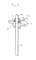
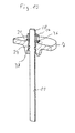
- FIG. 10 a further sealing variant between clamping bolt 11 and through hole 13.
- the clamping bolt 11 has here between the smooth-walled and the threaded Area 18 a widened bead-shaped portion 36, in which a circumferential groove 37 is incorporated, in which the O-ring 24 is located.
- the through hole 13 in the head part 7 is here in the area where the O-ring comes to rest 24, cylindrical.
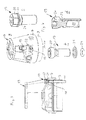
- Fig. 11 is a vertical multi-stage centrifugal pump in the region of the head part shown, in which the head part is higher than in the case of Fig. 2 or 3 constructed embodiment builds.
- an intermediate head part 34 incorporated, which means that the clamping bolt 11 would have to be formed at the same pump number of the pump longer than in the version according to Fig. 2 or 3 .
- the clamping bolt 11 in the basis of Fig. 11 that is, they consist of the actual clamping bolt 11 in the length, as would be provided for fixing the head part 7 and a clamping bolt part 11 a, which are connected to each other via a threaded sleeve 35.
- the components 11a and 35 are two-piece, but it can also be provided a clamping bolt portion 11a, which is provided at one end a threaded portion 18 and at the other end threaded sleeves 35 for receiving the threaded portion 18 of the adjoining clamping bolt 11.
- a clamping bolt portion 11a which is provided at one end a threaded portion 18 and at the other end threaded sleeves 35 for receiving the threaded portion 18 of the adjoining clamping bolt 11.
Landscapes
- Engineering & Computer Science (AREA)
- Mechanical Engineering (AREA)
- General Engineering & Computer Science (AREA)
- Structures Of Non-Positive Displacement Pumps (AREA)
Abstract
Description
- Die Erfindung betrifft eine mehrstufige Kreiselpumpe mit den im Oberbegriff des Anspruchs 1 angegebenen Merkmalen.
- Die Erfindung geht von einem Stand der Technik aus, wie er beispielsweise durch die Grundfos Pumpenbaureihen des Typs CR und CRE bekannt ist. Es handelt sich bei diesen Pumpen um mehrstufige, vertikal betriebene Kreiselpumpen, mit einem Fußteil und mit einem Kopfteil, zwischen denen mindestens zwei Pumpenstufen angeordnet sind, die jeweils ein Laufrad und ein dieses umgebendes Gehäuse aufweisen. Der Saug- und der Druckanschluss der Pumpe sind im Fußteil gebildet. Die zu fördernde Flüssigkeit gelangt durch einen Saugstutzen, der ebenfalls im Fußteil der Pumpe angeordnet ist, zunächst in die erste und weiter bis zur letzten Pumpenstufe, wo er über einen Ringkanal, der zwischen dem Außenmantel und den Gehäusen gebildet ist, wieder in das Fußteil zurückgeführt und dort über einen Saugstutzen aus der Pumpe heraus geführt wird. Die die Laufräder verbindende Antriebswelle der Pumpe ist durch den Kopfteil dichtend herausgeführt, wo sich ein Motorstuhl anschließt, welcher zur Aufnahme eines elektrischen Antriebsmotors vorgesehen ist, und in dem die pumpenseitige Welle der motorseitigen Welle bewegungsgekoppelt ist. Bei den vorgenannten Pumpenbaureihen handelt es sich um Pumpen, die vertikal betrieben sind, das heißt die auf dem Fußteil stehend mit vertikalen Laufradachsen betrieben werden, für die vorliegende Erfindung spielt es jedoch grundsätzlich keine Rolle, ob die Pumpe vertikal oder in einer beliebigen anderen Lage betrieben wird.
- Bei diesen bekannten Pumpen sind Kopf- und Fußteil typischerweise aus einem metallischen Gusswerkstoff gebildet, wohingegen der Außenmantel aus zu einem Zylinder geformten Blech besteht. Der Außenmantel und die Pumpenstufen sind zwischen Kopf und Fußteil eingespannt und werden durch vier Spannbolzen gehalten, die durch Bohrungen in den Zylinderkörper seitlich überragenden Ecken von Kopf- und Fußteil geführt sind.
- Die Pumpen der vorgenannten Baureihen haben sich bestens bewährt und sind in zahlreichen unterschiedlichen Leistungs- und Gehäuseausführungen im Markt eingeführt.
- Wenn solche Pumpen mit hohen Differenztemperaturen zwischen dem zu fördernden Medium und der Umgebung betrieben werden, können sich die Spannungsverhältnisse innerhalb der Pumpe in unerwünschter Weise ändern, da die Spannbolzen eine andere Wärmedehnung erfahren, als die Gehäuse der Pumpenstufen. Durch die mit geringem Abstand zum Gehäusemantel angeordneten Spannbolzen können sich Gegenstände oder umherfliegende Teile in diesem Bereich verklemmen oder zumindest ablagern, was unerwünscht ist. Auch stören diese Spannbolzen den optischen Gesamteindruck der Pumpe, der im Übrigen durch den meist aus Edelstahl gebildeten schlichten Zylindermantel geprägt ist. Eine Verkleidung der Spannbolzen ist jedoch aufwendig und teuer.
- Aus
US 2,957,426 zählt eine mehrstufige Pumpe zum Stand der Technik, bei welcher die Pumpenstufen wahlweise parallel oder in Reihe geschaltet werden können. Die einzelnen Pumpenstufen sind dort über Stehbolzen miteinander verbunden, die teils durch den Druckkanal verlaufen und die Pumpenstufen mit einem Endteil des Pumpengehäuses verbinden, welches sämtliche Pumpenstufen umfänglich und an einer Stirnseite mit Abstand umgibt. - Ausgehend von dem erstgenannten Stand der Technik liegt der vorliegenden Erfindung die Aufgabe zugrunde, eine gattungsgemäße mehrstufige Kreiselpumpe so auszubilden, dass die vorgenannten Nachteile vermieden, zumindest vermindert werden.
- Diese Aufgabe wird gemäß der Erfindung durch eine mehrstufige Kreiselpumpe mit den in Anspruch 1 angegebenen Merkmalen gelöst. Vorteilhafte Ausgestaltungen der Erfindung sind in den Unteransprüchen, der nachfolgenden Beschreibung sowie in den Figuren angegeben. Hierbei können die in den Unteransprüchen und der Beschreibung angegebenen Merkmale jeweils für sich, aber auch in geeigneter Kombination, die erfindungsgemäße Lösung gemäß Anspruch 1 weiter ausgestalten.
- Die erfindungsgemäße mehrstufige Kreiselpumpe weist einen Fußteil und einen Kopfteil auf, zwischen denen mindestens zwei Pumpenstufen angeordnet sind, die jeweils ein Laufrad und ein dieses umgebendes Gehäuse aufweisen. Diese Gehäuse werden mit Abstand von einem Außenmantel umgeben, so dass ein Ringkanal gebildet ist, wobei Spannbolzen vorgesehen sind, welche Kopfteil und Fußteil unter Einschluss von Mantel und den Gehäusen miteinander verbinden. Gemäß der Erfindung sind die Spannbolzen in dem Ringkanal zwischen dem Außenmantel und den Gehäusen angeordnet.
- Grundgedanke der vorliegenden Erfindung ist es somit, die Spannbolzen, welche die Pumpenstufen zwischen Kopfteil und Fußteil sowie den Außenmantel zwischen Kopfteil und Fußteil verspannen, nicht an der Außenseite des Außenmantels entlang zu führen, sondern innerhalb des Außenmantels, und zwar in dem durch die Gehäuse der Pumpenstufen und den Außenmantel gebildeten Ringkanal anzuordnen.
- Die erfindungsgemäße Anordnung hat zahlreiche Vorteile. Neben dem optisch ansprechenderen Erscheinungsbild der Pumpe wird durch den vom Außenmantel verdeckt angeordneten Spannbolzen verhindert, dass sich hier Gegenstände anlagern oder gar verklemmen.
- Ein wesentlicher technischer Vorteil besteht darin, dass durch die Anordnung der Spannbolzen im Ringkanal, also dort, wo Förderflüssigkeit entlangströmt, sichergestellt wird, dass Spannbolzen, Außenhaut und Pumpenstufe stets das gleiche Temperaturniveau, nämlich das der Förderflüssigkeit, aufweisen. Dies ist insbesondere vorteilhaft, wenn zum einen Förderflüssigkeiten mit stark schwankendem Temperaturniveau gefördert werden und zum anderen die Temperatur der Förderflüssigkeit von der Umgebungstemperatur der Pumpe stark abweicht. Durch die Anordnung der Spannbolzen innerhalb des Förderfluidstroms wird erreicht, dass die Wärmedehnungen des Spannbolzen einerseits und die der Pumpenstufen andererseits stets im Wesentlichen gleich erfolgen, so dass hier keine temperaturbedingten Belastungsspitzen auftreten können. Dabei ist davon auszugehen, dass sowohl die Pumpenstufen, zumindest jedoch die Gehäuse und die Spannbolzen, typischerweise auch die Außenhaut, aus artgleichen Materialien, typischerweise Metall bestehen, die einen im Wesentlichen gleichen Ausdehnungskoeffizienten aufweisen.
- Darüber hinaus hat sich gezeigt, dass die innerhalb des Ringkanals angeordneten Stehbolzen eine Art Führung für die Förderflüssigkeit bilden, so dass zumindest dann, wenn der Ringkanal druckseitig durchströmt wird, eine deutlich geringere Verwirbelung der Flüssigkeit am Druckstutzen auftritt, als dies bei vergleichbaren Pumpen konventioneller Bauart der Fall ist.
- Weiterhin wird durch das nach innen Verlegen der Spannbolzen die druckwirksame Fläche auf das Kopfteil bzw. das Fußteil um die Querschnittsfläche der Spannbolzen verkleinert.
- Vorteilhaft ist der Ringkanal so geschaltet, dass er den druckseitigen Ausgang vorzugsweise der letzten Pumpenstufe mit dem Druckanschluss der Pumpe fluidleitend verbindet, wie dies bei den eingangs genannten Pumpenbaureihen nach dem Stand der Technik der Fall ist. Bei dieser Anordnung ergeben sich strömungstechnisch die vorerwähnten Vorteile, darüber hinaus werden durch die Spannbolzen die druckwirksamen Flächen innerhalb des Pumpengehäuses und damit die wirksamen Kräfte verringert.
- Alternativ kann die erfindungsgemäße Kreiselpumpe jedoch auch so aufgebaut sein, dass der Ringkanal sauganschlussseitig vorgesehen ist, das heißt einen Sauganschluss der Pumpe mit einem Saugeingang vorzugsweise der ersten Pumpenstufe fluidleitend verbindet. Bei dieser Anordnung ist die Druckbelastung insbesondere des Außenmantels deutlich geringer als bei der anderen Variante.
- Konstruktiv von Vorteil ist es, wenn mindestens zwei Spannbolzen vorgesehen sind, die im gleichen Winkelabstand im Ringkanal angeordnet sind. Dies gewährt hinsichtlich der Krafteinleitung ein Minimum an Gleichmäßigkeit. Bevorzugt werden jedoch bei der erfindungsgemäßen Lösung vier Spannbolzen vorgesehen, die im Abstand von 90° winkelbezogen auf die Laufradachse gleichmäßig verteilt im Ringkanal angeordnet sind. Diese Anordnung ist sowohl hinsichtlich der Kraftverteilung als auch hinsichtlich der Strömungsführung besonders vorteilhaft.
- Wo die Spannbolzen innerhalb des Ringkanals angeordnet sind, ist grundsätzlich frei wählbar. Doch hat es sich als besonders vorteilhaft erwiesen, wenn die Spannbolzen in radialer Richtung in der Mitte des Ringkanals angeordnet sind, da sie dann günstig umströmt sind. Des Weiteren wird das Risiko von akustischem Lärm reduziert, der in dem Falle entstehen könnte, wenn der Außenmantel während des Betriebs die Spannbolzen berührt. Radial mittig bedeutet dabei zwischen der Innenseite des Außenmantels und den Außenseiten der Gehäuse der Pumpenstufen, und zwar mit gleichem radialem Abstand zu beiden.
- Vorteilhaft sind die Spannbolzen an mindestens einem Ende, vorzugsweise jedoch an beiden Enden mit einem Außengewinde versehen, so dass sie entweder beidseitig mittels Muttern verspannt werden können, die sich an dem Kopfteil bzw. Fußteil abstützen. Vorteilhaft können jedoch auch kopfteil- oder fußteilseitig Bohrungen vorgesehen sein, die mit einem Innengewinde versehen sind, in denen dann ein Ende eines Spannbolzens eingeschraubt werden kann, so dass eine Befestigung mittels der Mutter nur am anderen Ende erfolgt. Dabei sind die Bohrungen vorzugsweise als Durchgangsbohrungen ausgelegt, damit sich in der Bohrung keine korrosionsfördernde Flüssigkeit sammeln kann. Dabei kann anstelle einer Durchgangsbohrung auch eine Sacklochbohrung vorgesehen sein, die nahe dem Ende einen nach außen führenden Kanal, beispielsweise in Form einer Querbohrung, aufweist, um diese korrosionsfördernde Flüssigkeit gegebenenfalls nach außen abführen zu können. Alternativ kann ein Ende eines Spannbolzens auch über andere Formschlussmittel, beispielweise in Form eines Hakens oder eines radial aufgeweiteten zylindrischen Absatzes ausgebildet sein, der in eine entsprechende Aufnahme an der Innenseite des Fuß- oder Kopfteils eingreift. Wird beispielsweise ein Haken am Ende eines Spannbolzens vorgesehen, so ist fuß- oder kopfteilseitig ein Steg vorgesehen, in den dieser eingehakt werden kann. Auch kann eine geeignete andere formschlüssige Verbindung vorgesehen sein.
- Insbesondere dann, wenn der Ringkanal druckseitig angeordnet ist, aber auch bei saugseitiger Anordnung, ist es zweckmäßig, Dichtmittel zwischen Spannbolzen und Kopfteil und/oder Fußteil vorzusehen. Solche Dichtmittel sind dann vorzusehen, wenn der Spannbolzen oder ein damit in Verbindung stehendes Bauteil den Kopfteil oder den Fußteil durchsetzt. Gemäß der Erfindung sind eine Vielzahl von Lösungen zur Abdichtung dieses Bereichs vorgesehen, die weiter unten noch im Einzelnen beschrieben sind.
- Eine gute und zugleich kostengünstige Abdichtung ergibt sich, wenn eine Dichtung zwischen Spannbolzen und Durchgangsbohrung angeordnet ist und der Spannbolzen im Bereich dieser Dichtung gewindefrei ausgebildet ist. Dazu kann vorteilhaft eine O-Ring Dichtung dienen, diese ist kostengünstig und zuverlässig. An dem gewindefreien Teil des Spannbolzens kann der O-Ring dichtend vollumfänglich anliegen, eine Abdichtung ist also hier wesentlich effektiver und einfacher möglich als im Bereich des Gewindes. Durchgangsbohrungsseitig ist hier ebenfalls eine glatte zum Beispiel zylindrische Wand vorzusehen, gegebenenfalls können Absätze, Nuten oder sonstige Hilfsmittel vorgesehen sein, um die Dichtung, insbesondere den O-Ring, an der vorgesehenen Stelle zu halten.
- Zur Fixierung des O-Rings an der konstruktiv dafür vorgesehenen Stelle zwischen Spannbolzen und zum Beispiel der Durchgangsbohrung im Kopfteil ist gemäß einer Weiterbildung der Erfindung spannbolzenseitig ein nutartiger Dichtungssitz vorgesehen, der eine erste Anlageschulter aufweist, die durch einen Ring gebildet ist, der in einer Nut am Spannbolzen festgelegt ist und der eine zweite Anlageschulter aufweist, die durch einen weiteren Ring gebildet ist, der ein Innengewinde aufweist und der auf einem Gewindeabschnitt des Spannbolzens festgelegt ist. Dabei ist die Anordnung zweckmäßigerweise so, dass es sich um einen Gewindeabschnitt des Gewindes handelt, mit dem der Spannbolzen gehäuseseitig festgelegt und verspannt wird, also typischerweise an einem Abschnitt des an einem Ende vorgesehenen Außengewindes.
- Alternativ kann die Fixierung des Spannbolzens am Kopf- oder Fußteil mittels einer Hutmutter erfolgen, die einerseits einen die Durchgangsbohrung radial überragenden Kragen aufweist, mit dem sich diese jenseits der Durchgangsbohrung am Kopf- bzw. Fußteil abstützen kann. Weiterhin weist die Hutmutter einen hohlzylindrischen Abschnitt auf, der in die Durchgangsbohrung eingreift, an seinem Außenumfang eine umlaufende Nut als Dichtungssitz für den O-Ring aufweist und mit einem Innengewinde versehen ist, in welches das Gewinde am Ende des Zugankers eingreift.
- Alternativ kann ein Dichtungssitz für einen O-Ring durch einen mit einem Innengewinde versehenen Ring gebildet sein, der auf einem Gewindeabschnitt des Spannbolzens festgelegt ist. Durchgangsbohrungsseitig ist dann vorteilhaft eine umlaufende Nut vorgesehen, in welcher der O-Ring formschlüssig gehalten ist, um mit seiner Innenseite an dem durch den Ring gebildeten Dichtungssitz anzuliegen. Es muss nicht notwendigerweise eine Nut vorgesehen sein, es ist auch denkbar, dass nahe dem Ende der Durchgangsbohrung ein Absatz vorgesehen ist, in welchem der O-Ring aufgenommen ist. Dann kann der Dichtungssitz, also die Aufnahme für den O-Ring, durch diesen abgestuft aufgeweiteten Teil der Durchgangsbohrung in Verbindung mit einer abdeckenden Ringscheibe gebildet werden, wobei die Ringscheibe, die sonst die durch die Nut gebildete dritte Wandung in der Durchgangsbohrung ersetzt.
- Da gemäß der Erfindung die Spannbolzen innen liegen, also dort, wo sie für den Anwender nicht sichtbar sind, ist ein modularer Aufbau denkbar, beispielsweise aus Spannbolzenabschnitten, die an einem Ende mit einer mit einem Innengewinde versehenen Bohrung und am anderen Ende mit einem Außengewinde versehen sind, die somit zur Verlängerung eines Spannbolzens geeignet ist. Auf diese Weise können für Baureihen von Pumpen mit unterschiedlicher Stufenzahl baugleiche Spannbolzen verwendet werden, die durch eine oder mehrere geeignete Verlängerungen auf die erforderliche Länge gebracht werden. Somit können bei Pumpen mit unterschiedlichen Kopfteilen gleiche Spannbolzen verwendet werden, wobei eine erforderliche Anpassung durch ein solches Verlängerungsteil erfolgt.
- Vorteilhaft beträgt gemäß einer Weiterbildung der Erfindung das Verhältnis der für die Belastung der Spannbolzen druckwirksamen Flächen, die mit dem Ausgangsdruck der Pumpe und die mit dem Eingangsdruck der Pumpe belastet sind, mindestens zwei, vorzugsweise zwischen drei und fünf. Dieses Flächenverhältnis ist besonders vorteilhaft, da dann die innenliegende Anordnung der Spannbolzen praktisch keinen spürbaren Einfluss auf den Ausgangsdruck der Pumpe hat, so dass der Ausgangsdruck der Pumpe etwa dem entspricht, den eine vergleichbare Pumpe mit außen angeordneten Spannbolzen bei gleicher Antriebsleistung hervorbringt.
- Die Erfindung ist nachfolgend anhand von in den Figuren dargestellten Ausführungsbeispielen näher erläutert. Es zeigen:
- Fig. 1
- eine Draufsicht auf eine vertikale mehrstufige Kreiselpumpe der Inline Bauart,
- Fig. 2
- einen Schnitt längs der Schnittlinie A - A in
Fig. 1 , - Fig. 3
- in vergrößerter Teilschnittdarstellung den Kopfteil mit anschließendem Außenmantel und einer Zugankerverbindung der Pumpe nach
Fig. 1 , - Fig. 4a
- in schematischer perspektivischer Explosionsdarstellung einen Kopfteil mit Hutmutter zur Befestigung eines Zugankers,
- Fig. 4b
- in vergrößerter perspektivischer Explosionsdarstellung die Hutmutter mit Unterlegscheibe und Dichtring,
- Fig. 4c
- die Bauteile gemäß
Fig. 4b in montierter Form, - Fig. 4d
- die Hutmutter der
Fig. 4b im Längsschnitt, - Fig. 5
- in schematischer perspektivischer Längsschnittdarstellung eine kopfteilseitige Verbindung mit einem Zuganker,
- Fig. 6
- eine alternative Ausgestaltung der Verbindung in Darstellung nach
Fig. 5 , - Fig. 7
- in vergrößerter Schnittdarstellung eine Einzelheit einer Verbindung nach
Fig. 6 mit einem Kopfteil der Pumpe, - Fig. 8
- eine weitere Ausführungsform einer Verbindung zwischen Zuganker und Kopfteil in Darstellung nach
Fig. 5 , - Fig. 9
- eine weitere Ausgestaltung der Verbindung zwischen Zuganker und Kopfteil in Darstellung nach
Fig. 5 , - Fig. 10
- eine weitere Ausgestaltung der Verbindung zwischen Zuganker und Kopfteil in Darstellung nach
Fig. 5 und - Fig. 11
- eine schematische perspektivische Teilschnittdarstellung einer Befestigung des Zugankers an einem höher bauenden Kopfteil.
- Anhand der
Fig. 1 und 2 ist zunächst der grundsätzliche Aufbau der hier beschriebenen vertikalen mehrstufigen Kreiselpumpe dargestellt. Die Pumpe weist ein Fußteil 1 auf, auf welchem die Pumpe betrieben wird. Der Fußteil 1 weist einen Anschlussflansch 2 auf, der den Saugstutzen der Pumpe bildet und der einen Saugkanal 3 umgibt, der innerhalb eines im Fußteil 1 gebildeten Saugraums mündet, an den der Saugmund eines Kreiselrades 4 einer ersten Pumpenstufe anschließt, die durch das Kreiselrad 4 und ein dieses umgebendes Gehäuse 5 gebildet ist. Bei der anhand vonFig. 2 dargestellten Pumpe sind insgesamt fünf Stufen jeweils bestehend aus einem Kreiselrad 4 und einem Gehäuse 5 vertikal übereinander angeordnet, wobei die Kreiselräder 4 auf einer gemeinsamen Welle 6 sitzen, die drehbar innerhalb des Pumpengehäuses gelagert ist und an der Oberseite, nämlich im Bereich des Kopfteils 7, aus diesem herausgeführt ist. - Die Gehäuse 5 sind an ihrer Außenseite zylindrisch ausgebildet und dichtend aneinander angeordnet. Sie begrenzen einen Ringkanal 8 an der Innenseite, der außen durch einen Außenmantel 9 begrenzt wird, der aus Blech besteht und Teil des Pumpengehäuses bildet. Außenmantel 9 und die Gehäuse 5 sind zwischen Fußteil 1 und Kopfteil 7 eingespannt, die hierfür erforderlichen Spannkräfte werden durch vier in gleichem Winkelabstand um die Längsachse 10 der Pumpe, die auch die Drehachse 10 der Welle 6 bildet, verteilt angeordnete Zuganker in Form von Spannbolzen 11 gehalten.
- Jeder Spannbolzen 11 ist an seinen beiden Enden mit einem Außengewinde versehen, welches in einer mit Innengewinde versehenen Bohrung 12 am Fußteil 1 mit einem Ende eingeschraubt ist. Das andere Ende ist bei der Ausführung nach
Fig. 2 durch eine Durchgangsbohrung 13 im Kopfteil 7 geführt und dort mittels einer Mutter 14 verspannt. - Dieses anhand der
Fig. 2 dargestellte Konstruktionsprinzip kann sowohl hinsichtlich der fußteilseitigen Befestigung als auch hinsichtlich der kopfteilseitigen Befestigung, wie bereits einleitend erwähnt, variiert werden. Soweit es die kopfteilseitige Befestigung angeht, sind entsprechende Alternativen anhand derFig. 3 - 11 dargestellt, die jedoch auch für eine fußseitige Befestigung grundsätzlich geeignet sind. - Die vier Spannbolzen 11 sind nicht nur im gleichen Winkelabstand von 90° um die Längsachse 10 verteilt in dem Ringkanal 8 angeordnet, sondern auch radial mittig im Kanal 8 angeordnet, so dass sie den gleichen Abstand zur Außenseite der Gehäuse 5 und zur Innenseite des Außenmantels 9 aufweisen. Dieser Ringkanal 8 mündet innerhalb des Fußteils 1 in einem Druckkanal 15, der zu einem Druckanschluss 16 führt, dessen Anschlussflansch in den
Fig. 1 und 2 sichtbar ist. - Der Kopfteil 7 der Pumpe ist nach oben hin verlängert und dort in an sich bekannter Weise zu einem Motorstuhl 17 ausgebildet, welcher zur Befestigung des darauf zur Anlage kommenden elektrischen Antriebsmotors vorgesehen ist, dessen Welle über eine hier nicht dargestellte Kupplung mit dem freien Ende der Welle 6 drehfest verbunden ist.
- Da die Spannbolzen 11 in Durchgangsbohrungen 13 des Kopfteils festgelegt sind, müssen diese gegenüber dem Kopfteil abgedichtet sein, um die Dichtheit des Gehäuses in diesem Bereich sicherzustellen. Bei der anhand von
Fig. 3 dargestellten Ausführung reicht das kopfteilseitige mit Gewinde versehene Ende 18 des Spannbolzen 11 nicht durch die Durchgangsbohrung 13 hindurch, sondern nur bis in diese hinein. Aufgenommen wird das mit Gewinde versehene Ende 18 des Spannbolzens 11 in einer Hutmutter 19, wie diese anhand derFig. 4 im Einzelnen dargestellt ist. Diese Hutmutter 19 weist einen Kopf 20 auf, der bei der dargestellten Ausführungsform sowohl einen Innensechskant als auch einen Außensechskant zur Aufnahme eines Werkzeuges hat und größenmäßig so ausgelegt ist, dass er die Durchgangsbohrung 13 radial überragt. Dieser radial auskragende Kopf liegt über einer Unterlegescheibe 21 in montiertem Zustand an der entsprechend oberhalb der Durchgangsbohrung 13 im Kopfteil 7 ausgebildeten Schraubenkopfauflagefläche 22 an. - Vom Kopf 20 an ist die Hutmutter 19 zylindrisch ausgebildet, wobei in kurzem Abstand hinter dem Kopf eine umlaufende Nut 23 vorgesehen ist, die zur Aufnahme eines O-Rings 24 dient, der innerhalb dieser Nut 23 gehalten ist und der die Hutmutter 19 innerhalb der Durchgangsbohrung 13 im Kopfteil 7 abdichtet. Jenseits der Nut 23 ist die Hutmutter hohlzylindrisch ausgebildet und weist ein Innengewinde 25 auf, in welcher das mit Gewinde versehene Ende 18 des Spannbolzens 11 eingreift. Mit dieser Hutmutter 19 wird der Spannbolzen 11, der mit seinem anderen Ende im Fußteil 1 festgelegt ist, verspannt und gegenüber der Durchgangsbohrung 13 mittels der Dichtung in Form des O-Rings 24 abgedichtet.
- Anhand von
Fig. 5 ist eine kopfteilseitige Befestigung des Spannbolzens 11 mittels einer Hutmutter 26 dargestellt, die sich von der vorbeschriebenen Hutmutter 19 dadurch unterscheidet, dass die dort vorgesehene Unterlegscheibe 21 durch entsprechende Ausbildung der ringförmigen Fläche unterhalb des Kopfes sowie der Kopfauflagefläche entfallen kann. Das Kopfteil 7 ist dort nur im Bereich der Durchgangsbohrung dargestellt, da in dieser Darstellung nur die Befestigung und Abdichtung gezeigt werden soll. Die Durchgangsbohrung 13 ist zum Inneren des Pumpengehäuses hin aufgeweitet, dieser aufgeweitete Bereich ist mit 27 gekennzeichnet und schließt sich zum Inneren des Pumpengehäuses an den zylindrischen Teil der Durchgangsbohrung 13 an, an dem der in der Nut 23 der Hutmutter 26 liegende O-Ring 24 dichtend anliegt. In dem zylindrischen Bereich der Hutmutter 26, in dem diese mit dem Innengewinde 25 versehen ist, ist nahe dem inneren Ende eine Querbohrung 28 vorgesehen, die die Hutmutter 26 quer durchsetzt und die einerseits in dem mit Innengewinde versehenen Sackloch der Hutmutter 26 und andererseits in dem aufgeweiteten Bereich 27 der Durchgangsbohrung 13 mündet, so dass sichergestellt ist, dass innerhalb der Hutmutter 26 kein Totraum gebildet ist, in dem sich korrosionsfördernde Flüssigkeit ansammeln kann. Damit diese Querbohrung 28 nicht durch den mit Gewinde versehenden Teil 18 des Spannbolzens 11 umschlossen wird, ist bei dieser Ausführung der Spannbolzen 11 im Bereich zwischen seinem Schaft und dem Gewindeende 18 mit einem umlaufenden Wulst 29 versehen, der ein zu weites Eindrehen in das Innengewinde 25 der Hutmutter verhindert. - Bei der anhand von
Fig. 6 und 7 dargestellten Ausführung durchsetzt der Spannbolzen 11 die Durchgangsbohrung 13 vollständig und ist dort an seinem mit Gewinde versehenen Ende 18 mittels der Mutter 14 unter Eingliederung einer Unterlegscheibe 21 im Kopfteil 7 festgelegt. Der Spannbolzen 11, der bei der Ausführung nachFig. 6 aus Stahlrundmaterial hergestellt ist, weist an seinen Enden mit Gewinde versehene Abschnitte 18 auf, die durch Rollen hergestellt sind, so dass der Durchmesser geringfügig größer ist als der nicht mit Gewinde versehene Bereich, wie dies ausFig. 7 ersichtlich ist. Die Durchgangsbohrung 13 ist abgesetzt ausgebildet, so dass in diesem Bereich ein Freiraum zwischen dem Spannbolzen 11 und der Durchgangsbohrung 13 gebildet ist, welcher die Eingliederung des Dichtrings in Form des O-Rings 24 ermöglicht. Da die Durchgangsbohrung 13 auch im abgesetzten Bereich glattwandig ausgebildet ist, sind zum Halten des O-Rings 24 in seiner bestimmungsgemäßen Stellung zwei Ringe 30 und 31 vorgesehen, die auf dem Spannbolzen 11 klemmbefestigt sind und die den O-Ring 24 aufnehmen. Diese Ringe können kraftschlüssig oder auch stoffschlüssig auf dem Spannbolzen 11 sitzen. Es kann der Ring 30 mit einem Innengewinde versehen sein, das auf das dann gegenüberFig. 7 länger ausgeführte Gewinde am Abschnitt 18 von der Mitte her aufschraubbar ist, der Ring 31 kann über eine Nut im Spannbolzen 11 fixiert sein. Die Ringe 30 und 31 können zweiteilig ausgebildet und klippbefestigt sein, sie können aus Kunststoff bestehen, da sie kräftemäßig nur gering belastet sind. Bei der anhand vonFig. 8 dargestellten Ausführung ist der Spannbolzen 11 aus Rundmaterial aus Stahl hergestellt, allerdings ist das mit Gewinde versehene Ende 18 dort nicht durch Rollen, sondern durch Schneiden hergestellt, so dass der Gewindeabschnitt 18 einen geringeren Durchmesser als der übrige Teil des Spannbolzens 11 aufweist. Die Befestigung des Spannbolzens 11 ist grundsätzlich wie anhand vonFig. 6 beschrieben mittels einer Mutter 14 unter Eingliederung einer Unterlegscheibe 21 möglich. Die Abdichtung zwischen dem Spannbolzen 11 und der Durchgangsbohrung 13 erfolgt ebenfalls mittels des O-Rings 24, der in dem Bereich des Spannbolzens 11 angeordnet ist, der kein Gewinde trägt. Um den O-Ring 24 in seiner Lage zu sichern, ist der inFig. 8 obere Teil der Durchgangsbohrung 13 abgesetzt ausgebildet, so dass der O-Ring 24 am Außenumfang und an der Unterseite durch diesen abgesetzten Teil der Durchgangsbohrung, an der Innenseite durch Spannbolzen 11 und an der Oberseite durch die Unterlegscheibe 21 gehalten ist. - Bei der Ausführung nach
Fig. 9 erfolgt die Festlegung des O-Rings innerhalb eines gesonderten Bauteils 32, welches einerseits die Funktion einer Unterlegscheibe aufweist, andererseits jedoch an der Innenseite abgesetzt ausgebildet ist, so dass der O-Ring 24 in diesem abgesetzten Teil des Bauteils 32 der inFig. 9 mit 33 gekennzeichnet ist, aufgenommen ist. Der O-Ring 24 muss bei dieser Anordnung zum Spannbolzen 11 einerseits sowie zur Kopfauflagefläche 22 der Durchgangsbohrung 13 abdichten. - Schließlich zeigt
Fig. 10 eine weitere Abdichtungsvariante zwischen Spannbolzen 11 und Durchgangsbohrung 13. Der Spannbolzen 11 weist hier zwischen dem glattwandigen und dem mit Gewinde versehenen Bereich 18 einen aufgeweiteten wulstförmigen Bereich 36 auf, in den eine umlaufende Nut 37 eingearbeitet ist, in welcher der O-Ring 24 liegt. Die Durchgangsbohrung 13 im Kopfteil 7 ist hier in dem Bereich, wo der O-Ring zur Anlage 24 kommt, zylindrisch ausgebildet. - Anhand von
Fig. 11 ist eine vertikale mehrstufige Kreiselpumpe im Bereich des Kopfteils dargestellt, bei der das Kopfteil höher als bei der anhand vonFig. 2 oder3 dargestellten Ausführung baut. Dort ist nämlich zwischen dem eigentlichen Kopfteil 7 und dem Außenmantel 9 ein Zwischenkopfteil 34 eingegliedert, was dazu führt, dass die Spannbolzen 11 bei gleicher Pumpenstufenzahl der Pumpe länger ausgebildet sein müssten als bei der Version gemäßFig. 2 oder3 . Hierzu sind die Spannbolzen 11 bei der anhand vonFig. 11 dargestellten Ausführungsvariante mehrteilig aufgebaut, sie bestehen nämlich aus dem eigentlichen Spannbolzen 11 in der Länge, wie er zur Befestigung des Kopfteils 7 vorgesehen wäre und einem Spannbolzenteil 11a, die über eine Gewindemuffe 35 miteinander verbunden sind. In der dargestellten Ausführung sind die Bauteile 11a und 35 zweistückig, es kann jedoch auch ein Spannbolzenabschnitt 11a vorgesehen sein, der an einem Ende einen Gewindeabschnitt 18 und am anderen Ende Gewindemuffen 35 zur Aufnahme des Gewindeabschnitts 18 des sich daran anschließenden Spannbolzens 11 vorgesehen ist. Auf diese Weise ist es möglich, einen Spannbolzen modular aufzubauen, so dass bei geeigneter Wahl der Modullängen mit einer vergleichsweise geringen Anzahl von Spannbolzen 11 und Spannbolzenverlängerungen 11a unterschiedliche Bauformen und gesamte Baureihen hinsichtlich der Spannbolzen abgedeckt werden können, ohne dass eine vergleichbare Anzahl unterschiedlich langer Spannbolzen erforderlich wäre. -
- 1
- Fußteil
- 2
- Anschlussflansch des Saugkanals
- 3
- Saugkanal
- 4
- Kreiselrad
- 5
- Gehäuse
- 6
- Welle
- 7
- Kopfteil
- 8
- Ringkanal
- 9
- Außenmantel
- 10
- Längsachse, Drehachse
- 11
- Spannbolzen
- 11a
- Spannbolzenverlängerung
- 12
- Bohrung im Fußteil
- 13
- Durchgangsbohrung im Kopfteil
- 14
- Mutter
- 15
- Druckkanal
- 16
- Druckanschluss
- 17
- Motorstuhl
- 18
- Mit Gewinde versehenes Ende von 11
- 19
- Hutmutter
- 20
- Kopf der Hutmutter
- 21
- Unterlegscheibe
- 22
- Kopfauflage
- 23
- Nut der Hutmutter
- 24
- O-Ring
- 25
- Innengewinde in der Hutmutter
- 26
- Hutmutter in
Fig. 5 - 27
- aufgeweiteter Bereich von 13
- 28
- Querbohrung
- 29
- Wulst
- 30
- Ring
- 31
- Ring
- 32
- Bauteil
- 33
- abgesetzter Teil
- 34
- Zwischenkopfteil
- 35
- Gewindemuffe
- 36
- wulstförmiger Bereich
- 37
- Nut
Claims (16)
- Mehrstufige Kreiselpumpe mit einem Fußteil (1) und mit einem Kopfteil (7), zwischen denen mindestens zwei Pumpenstufen angeordnet sind, die jeweils ein Laufrad (4) und ein dieses umgebendes Gehäuse (5) aufweisen, mit einem die Gehäuse (5) mit Abstand umgebenden und einen Ringkanal (8) bildenden Außenmantel (9) und mit Spannbolzen (11), welche Kopfteil (7) und Fußteil (1) unter Einschluss von Mantel (9) und den Gehäusen (5) miteinander verbinden, dadurch gekennzeichnet, dass die Spannbolzen (11) in dem Ringkanal (8) angeordnet sind.
- Kreiselpumpe nach Anspruch 1, dadurch gekennzeichnet, dass der Ringkanal (8) einen druckseitigen Ausgang mindestens einer Pumpenstufe mit einem Druckanschluss (16) der Pumpe fluidleitend verbindet.
- Kreiselpumpe nach Anspruch 1, dadurch gekennzeichnet, dass der Ringkanal (8) einen Sauganschluss (2) der Pumpe mit einem Saugeingang mindestens einer Pumpenstufe fluidleitend verbindet.
- Kreiselpumpe nach einem der vorhergehenden Ansprüche, dadurch gekennzeichnet, dass mindestens zwei, vorzugsweise vier Spannbolzen (11) in gleichem Winkelabstand im Ringkanal (8) angeordnet sind.
- Kreiselpumpe nach einem der vorhergehenden Ansprüche, dadurch gekennzeichnet, dass die Spannbolzen (11) jeweils radial mittig zwischen der Innenseite des Außenmantels (9) und den Außenseiten der Gehäuse (5) angeordnet sind.
- Kreiselpumpe nach einem der vorhergehenden Ansprüche, dadurch gekennzeichnet, dass die Spannbolzen (11) an mindestens einem Ende, vorzugsweise an beiden Enden, mit einem Außengewinde (18) versehen sind.
- Kreiselpumpe nach einem der vorhergehenden Ansprüche, dadurch gekennzeichnet, dass die Spannbolzen (11) fußteilseitig oder kopfteilseitig in mit Innengewinde versehenen Bohrungen (12), vorzugsweise Durchgangsbohrungen (13), befestigt sind.
- Kreiselpumpe nach einem der vorhergehenden Ansprüche, dadurch gekennzeichnet, dass die Spannbolzen (11) kopfteilseitig oder fußteilseitig bis zu/durch Durchgangsbohrungen (13) im Kopfteil (7) bzw. Fußteil (1) geführt und mittels Muttern (14; 19; 26) befestigt sind.
- Kreiselpumpe nach einem der vorgehenden Ansprüche, dadurch gekennzeichnet, dass Dichtmittel (24) zwischen Spannbolzen (11) und Kopfteil (7) und/oder Fußteil (1) vorgesehen sind.
- Kreiselpumpe nach einem der vorhergehenden Ansprüche, dadurch gekennzeichnet, dass eine Dichtung, vorzugsweise ein O-Ring (24) zwischen Spannbolzen (11) und Durchgangsbohrung (13) angeordnet ist und dass der Spannbolzen (11) im Bereich der Dichtung (24) gewindefrei ist.
- Kreiselpumpe nach Anspruch 10, dadurch gekennzeichnet, dass auf dem Spannbolzen (11) ein nutartiger Dichtungssitz für einen O-Ring (24) gebildet ist, mit einer ersten Anlageschulter, die durch einen Ring (31) gebildet ist, der in einer Nut am Spannbolzen (11) festgelegt ist und mit einer zweiten Anlageschulter, die durch einen Ring (30) mit einem Innengewinde gebildet ist, der auf einem Gewindeabschnitt (18) des Spannbolzens (11) festgelegt ist.
- Kreiselpumpe nach einem der vorhergehenden Ansprüche, dadurch gekennzeichnet, dass die Muttern (19; 26) als Hutmuttern ausgebildet sind, jeweils einen die Durchgangsbohrung radial überragenden Kragen (20) sowie im Bereich der Durchgangsbohrung (13) eine umlaufende Nut (23) als Dichtungssitz für einen O-Ring (24) aufweisen.
- Kreiselpumpe nach einem der vorhergehenden Ansprüche, dadurch gekennzeichnet, dass ein Dichtungssitz für einen O-Ring (24) durch einen Ring mit einem Innengewinde gebildet ist, der auf einem Gewindeabschnitt des Spannbolzens festgelegt ist, in Verbindung mit einer umlaufenden Nut (35) in der zugehörigen Durchgangsbohrung.
- Kreiselpumpe nach einem der vorhergehenden Ansprüche, dadurch gekennzeichnet, dass ein Dichtungssitz durch den abgestuft aufgeweiteten Teil einer Durchgangsbohrung (13) in Verbindung mit einer abdeckenden Ringscheibe (21) gebildet ist (Fig. 8).
- Kreiselpumpe nach einem der vorhergehenden Ansprüche, dadurch gekennzeichnet, dass ein Spannbolzen (11) zwei- oder mehrteilig aus Spannbolzenabschnitten (11a) aufgebaut ist, die durch Gewindeverbindungen (35) miteinander verbunden sind.
- Kreiselpumpe nach einem der vorhergehenden Ansprüche, dadurch gekennzeichnet, dass das Verhältnis der für die Belastung der Spannbolzen (11) druckwirksamen Flächen, die mit dem Ausgangsdruck der Pumpe und die mit dem Eingangsdruck der Pumpe belastet sind mindestens zwei, vorzugsweise zwischen drei und fünf beträgt.
Priority Applications (3)
| Application Number | Priority Date | Filing Date | Title |
|---|---|---|---|
| EP14188999.8A EP3009680B1 (de) | 2014-10-15 | 2014-10-15 | Mehrstufige Kreiselpumpe |
| US14/882,750 US10094385B2 (en) | 2014-10-15 | 2015-10-14 | Multi-stage centrifugal pump |
| CN201510666768.7A CN105526195A (zh) | 2014-10-15 | 2015-10-15 | 多级离心泵 |
Applications Claiming Priority (1)
| Application Number | Priority Date | Filing Date | Title |
|---|---|---|---|
| EP14188999.8A EP3009680B1 (de) | 2014-10-15 | 2014-10-15 | Mehrstufige Kreiselpumpe |
Publications (2)
| Publication Number | Publication Date |
|---|---|
| EP3009680A1 true EP3009680A1 (de) | 2016-04-20 |
| EP3009680B1 EP3009680B1 (de) | 2019-11-13 |
Family
ID=51703049
Family Applications (1)
| Application Number | Title | Priority Date | Filing Date |
|---|---|---|---|
| EP14188999.8A Active EP3009680B1 (de) | 2014-10-15 | 2014-10-15 | Mehrstufige Kreiselpumpe |
Country Status (3)
| Country | Link |
|---|---|
| US (1) | US10094385B2 (de) |
| EP (1) | EP3009680B1 (de) |
| CN (1) | CN105526195A (de) |
Cited By (1)
| Publication number | Priority date | Publication date | Assignee | Title |
|---|---|---|---|---|
| EP3670919A1 (de) * | 2018-12-20 | 2020-06-24 | Grundfos Holding A/S | Pumpenanordnung |
Families Citing this family (4)
| Publication number | Priority date | Publication date | Assignee | Title |
|---|---|---|---|---|
| EP3171033A1 (de) * | 2015-11-19 | 2017-05-24 | Grundfos Holding A/S | Mehrstufige kreiselpumpe mit gehäuseöffnung zur wartung eines axialschub-kolbens |
| EP3343054A1 (de) | 2016-12-28 | 2018-07-04 | Grundfos Holding A/S | Lagerkäfig für mehrstufige kreiselpumpe |
| CN111536046A (zh) * | 2019-12-19 | 2020-08-14 | 合肥皖化电泵有限公司 | 多级输送泵 |
| CN116591997B (zh) * | 2023-06-14 | 2026-02-03 | 扎赉诺尔煤业有限责任公司 | 带有自拆功能的离心泵 |
Citations (7)
| Publication number | Priority date | Publication date | Assignee | Title |
|---|---|---|---|---|
| US2753807A (en) * | 1952-01-21 | 1956-07-10 | Tait Mfg Co The | Centrifugal pump and method of manufacture therefor |
| DE1072100B (de) * | 1956-10-02 | 1959-12-24 | ||
| US2957426A (en) | 1956-12-17 | 1960-10-25 | Ralph C Miller | Series-parallel pump |
| US3051090A (en) * | 1960-08-04 | 1962-08-28 | Worthington Corp | Segmented casing for multistage centrifugal fluid machines |
| DE1275866B (de) * | 1963-06-11 | 1968-08-22 | Klein Schanzlin & Becker Ag | Mehrstufige doppelflutige Unterwasser-Kreiselpumpe in Gliederbauart, insbesondere Bohrlochpumpe |
| DE3240259C1 (de) * | 1982-10-30 | 1984-02-16 | Klein, Schanzlin & Becker Ag, 6710 Frankenthal | Saugstufe fuer mehrstufige Kreiselpumpen |
| EP2348221A1 (de) * | 2010-01-25 | 2011-07-27 | Grundfos Management A/S | Kreiselpumpenaggregat |
Family Cites Families (3)
| Publication number | Priority date | Publication date | Assignee | Title |
|---|---|---|---|---|
| CH666093A5 (de) * | 1985-05-30 | 1988-06-30 | Sulzer Ag | Schraubverbindung. |
| DE3629123C3 (de) * | 1986-08-27 | 1994-04-28 | Grundfos International A S Bje | Mehrstufige Inline-Kreiselpumpe |
| DE29817337U1 (de) * | 1998-09-26 | 1998-12-17 | Grundfos A/S, Bjerringbro | Kreiselpumpe der Inline-Bauart zum Fördern heißer Flüssigkeiten |
-
2014
- 2014-10-15 EP EP14188999.8A patent/EP3009680B1/de active Active
-
2015
- 2015-10-14 US US14/882,750 patent/US10094385B2/en not_active Expired - Fee Related
- 2015-10-15 CN CN201510666768.7A patent/CN105526195A/zh active Pending
Patent Citations (7)
| Publication number | Priority date | Publication date | Assignee | Title |
|---|---|---|---|---|
| US2753807A (en) * | 1952-01-21 | 1956-07-10 | Tait Mfg Co The | Centrifugal pump and method of manufacture therefor |
| DE1072100B (de) * | 1956-10-02 | 1959-12-24 | ||
| US2957426A (en) | 1956-12-17 | 1960-10-25 | Ralph C Miller | Series-parallel pump |
| US3051090A (en) * | 1960-08-04 | 1962-08-28 | Worthington Corp | Segmented casing for multistage centrifugal fluid machines |
| DE1275866B (de) * | 1963-06-11 | 1968-08-22 | Klein Schanzlin & Becker Ag | Mehrstufige doppelflutige Unterwasser-Kreiselpumpe in Gliederbauart, insbesondere Bohrlochpumpe |
| DE3240259C1 (de) * | 1982-10-30 | 1984-02-16 | Klein, Schanzlin & Becker Ag, 6710 Frankenthal | Saugstufe fuer mehrstufige Kreiselpumpen |
| EP2348221A1 (de) * | 2010-01-25 | 2011-07-27 | Grundfos Management A/S | Kreiselpumpenaggregat |
Cited By (2)
| Publication number | Priority date | Publication date | Assignee | Title |
|---|---|---|---|---|
| EP3670919A1 (de) * | 2018-12-20 | 2020-06-24 | Grundfos Holding A/S | Pumpenanordnung |
| CN111350669A (zh) * | 2018-12-20 | 2020-06-30 | 格兰富控股联合股份公司 | 泵组件 |
Also Published As
| Publication number | Publication date |
|---|---|
| EP3009680B1 (de) | 2019-11-13 |
| US10094385B2 (en) | 2018-10-09 |
| US20160108922A1 (en) | 2016-04-21 |
| CN105526195A (zh) | 2016-04-27 |
Similar Documents
| Publication | Publication Date | Title |
|---|---|---|
| EP2818721B1 (de) | Kreiselpumpe | |
| EP3009680B1 (de) | Mehrstufige Kreiselpumpe | |
| EP3156661B1 (de) | Hauswasserwerk oder pumpe mit einem rückschlagventil | |
| EP3181908B1 (de) | Mehrstufige kreiselpumpe mit aus blech gebildeten zugankern | |
| EP2143953B1 (de) | Pumpenaggregat | |
| WO2011035985A1 (de) | Adapter sowie pumpenanlage | |
| EP2233747B1 (de) | Mehrstufiges Kreiselpumpenaggregat | |
| EP3139074B1 (de) | Frostsichere aussenarmatur und verfahren zur montage derselben | |
| EP3441619A1 (de) | Kreiselpumpe | |
| DE102013111716B3 (de) | Exzenterschneckenpumpe und Verwendung einer Exzenterschneckenpumpe | |
| DE102009039120A1 (de) | Vakuumpumpe | |
| EP3029334B1 (de) | Axial geteilte pumpe | |
| EP1509308B1 (de) | Vorrichtung zum filtern von unter einem hohen druck geförderten fluiden | |
| EP2078864B1 (de) | Rohrventilator | |
| EP2636901A1 (de) | Hochdruckeinrichtung für flüssige Medien | |
| DE2719168C2 (de) | Gehäuse für eine Kreiselpumpe | |
| EP3085961B1 (de) | Mehrstufige kreiselpumpe | |
| EP2818722B1 (de) | Kreiselpumpe | |
| DE10344721B4 (de) | Seitenkanalverdichter | |
| DE102007012661B4 (de) | Tauchpumpenaggregat | |
| WO2018130463A1 (de) | Exzenterschneckenpumpe | |
| DE102005002913B4 (de) | Absperrvorrichtung zum Absperren einer Rohrleitung | |
| CH712158B1 (de) | Schlauch, insbesondere Brauseschlauch. | |
| EP1170509A2 (de) | Fluidleitendes Gehäuseendteil für eine Kreiselpumpe | |
| EP0831265B1 (de) | Flanscharmatur |
Legal Events
| Date | Code | Title | Description |
|---|---|---|---|
| PUAI | Public reference made under article 153(3) epc to a published international application that has entered the european phase |
Free format text: ORIGINAL CODE: 0009012 |
|
| AK | Designated contracting states |
Kind code of ref document: A1 Designated state(s): AL AT BE BG CH CY CZ DE DK EE ES FI FR GB GR HR HU IE IS IT LI LT LU LV MC MK MT NL NO PL PT RO RS SE SI SK SM TR |
|
| AX | Request for extension of the european patent |
Extension state: BA ME |
|
| 17P | Request for examination filed |
Effective date: 20161018 |
|
| RBV | Designated contracting states (corrected) |
Designated state(s): AL AT BE BG CH CY CZ DE DK EE ES FI FR GB GR HR HU IE IS IT LI LT LU LV MC MK MT NL NO PL PT RO RS SE SI SK SM TR |
|
| GRAP | Despatch of communication of intention to grant a patent |
Free format text: ORIGINAL CODE: EPIDOSNIGR1 |
|
| STAA | Information on the status of an ep patent application or granted ep patent |
Free format text: STATUS: GRANT OF PATENT IS INTENDED |
|
| RIC1 | Information provided on ipc code assigned before grant |
Ipc: F04D 17/12 20060101ALI20190513BHEP Ipc: F04D 1/06 20060101AFI20190513BHEP Ipc: F04D 29/62 20060101ALI20190513BHEP Ipc: F04D 13/02 20060101ALI20190513BHEP Ipc: F04D 29/42 20060101ALI20190513BHEP |
|
| INTG | Intention to grant announced |
Effective date: 20190603 |
|
| GRAS | Grant fee paid |
Free format text: ORIGINAL CODE: EPIDOSNIGR3 |
|
| GRAA | (expected) grant |
Free format text: ORIGINAL CODE: 0009210 |
|
| STAA | Information on the status of an ep patent application or granted ep patent |
Free format text: STATUS: THE PATENT HAS BEEN GRANTED |
|
| AK | Designated contracting states |
Kind code of ref document: B1 Designated state(s): AL AT BE BG CH CY CZ DE DK EE ES FI FR GB GR HR HU IE IS IT LI LT LU LV MC MK MT NL NO PL PT RO RS SE SI SK SM TR |
|
| REG | Reference to a national code |
Ref country code: CH Ref legal event code: EP Ref country code: AT Ref legal event code: REF Ref document number: 1201937 Country of ref document: AT Kind code of ref document: T Effective date: 20191115 |
|
| REG | Reference to a national code |
Ref country code: DE Ref legal event code: R096 Ref document number: 502014013043 Country of ref document: DE |
|
| REG | Reference to a national code |
Ref country code: IE Ref legal event code: FG4D Free format text: LANGUAGE OF EP DOCUMENT: GERMAN |
|
| REG | Reference to a national code |
Ref country code: NL Ref legal event code: MP Effective date: 20191113 |
|
| REG | Reference to a national code |
Ref country code: LT Ref legal event code: MG4D |
|
| PG25 | Lapsed in a contracting state [announced via postgrant information from national office to epo] |
Ref country code: GR Free format text: LAPSE BECAUSE OF FAILURE TO SUBMIT A TRANSLATION OF THE DESCRIPTION OR TO PAY THE FEE WITHIN THE PRESCRIBED TIME-LIMIT Effective date: 20200214 Ref country code: NO Free format text: LAPSE BECAUSE OF FAILURE TO SUBMIT A TRANSLATION OF THE DESCRIPTION OR TO PAY THE FEE WITHIN THE PRESCRIBED TIME-LIMIT Effective date: 20200213 Ref country code: NL Free format text: LAPSE BECAUSE OF FAILURE TO SUBMIT A TRANSLATION OF THE DESCRIPTION OR TO PAY THE FEE WITHIN THE PRESCRIBED TIME-LIMIT Effective date: 20191113 Ref country code: PL Free format text: LAPSE BECAUSE OF FAILURE TO SUBMIT A TRANSLATION OF THE DESCRIPTION OR TO PAY THE FEE WITHIN THE PRESCRIBED TIME-LIMIT Effective date: 20191113 Ref country code: LT Free format text: LAPSE BECAUSE OF FAILURE TO SUBMIT A TRANSLATION OF THE DESCRIPTION OR TO PAY THE FEE WITHIN THE PRESCRIBED TIME-LIMIT Effective date: 20191113 Ref country code: LV Free format text: LAPSE BECAUSE OF FAILURE TO SUBMIT A TRANSLATION OF THE DESCRIPTION OR TO PAY THE FEE WITHIN THE PRESCRIBED TIME-LIMIT Effective date: 20191113 Ref country code: PT Free format text: LAPSE BECAUSE OF FAILURE TO SUBMIT A TRANSLATION OF THE DESCRIPTION OR TO PAY THE FEE WITHIN THE PRESCRIBED TIME-LIMIT Effective date: 20200313 Ref country code: SE Free format text: LAPSE BECAUSE OF FAILURE TO SUBMIT A TRANSLATION OF THE DESCRIPTION OR TO PAY THE FEE WITHIN THE PRESCRIBED TIME-LIMIT Effective date: 20191113 Ref country code: BG Free format text: LAPSE BECAUSE OF FAILURE TO SUBMIT A TRANSLATION OF THE DESCRIPTION OR TO PAY THE FEE WITHIN THE PRESCRIBED TIME-LIMIT Effective date: 20200213 Ref country code: FI Free format text: LAPSE BECAUSE OF FAILURE TO SUBMIT A TRANSLATION OF THE DESCRIPTION OR TO PAY THE FEE WITHIN THE PRESCRIBED TIME-LIMIT Effective date: 20191113 |
|
| PG25 | Lapsed in a contracting state [announced via postgrant information from national office to epo] |
Ref country code: IS Free format text: LAPSE BECAUSE OF FAILURE TO SUBMIT A TRANSLATION OF THE DESCRIPTION OR TO PAY THE FEE WITHIN THE PRESCRIBED TIME-LIMIT Effective date: 20200313 Ref country code: RS Free format text: LAPSE BECAUSE OF FAILURE TO SUBMIT A TRANSLATION OF THE DESCRIPTION OR TO PAY THE FEE WITHIN THE PRESCRIBED TIME-LIMIT Effective date: 20191113 Ref country code: HR Free format text: LAPSE BECAUSE OF FAILURE TO SUBMIT A TRANSLATION OF THE DESCRIPTION OR TO PAY THE FEE WITHIN THE PRESCRIBED TIME-LIMIT Effective date: 20191113 |
|
| PG25 | Lapsed in a contracting state [announced via postgrant information from national office to epo] |
Ref country code: AL Free format text: LAPSE BECAUSE OF FAILURE TO SUBMIT A TRANSLATION OF THE DESCRIPTION OR TO PAY THE FEE WITHIN THE PRESCRIBED TIME-LIMIT Effective date: 20191113 |
|
| PG25 | Lapsed in a contracting state [announced via postgrant information from national office to epo] |
Ref country code: ES Free format text: LAPSE BECAUSE OF FAILURE TO SUBMIT A TRANSLATION OF THE DESCRIPTION OR TO PAY THE FEE WITHIN THE PRESCRIBED TIME-LIMIT Effective date: 20191113 Ref country code: DK Free format text: LAPSE BECAUSE OF FAILURE TO SUBMIT A TRANSLATION OF THE DESCRIPTION OR TO PAY THE FEE WITHIN THE PRESCRIBED TIME-LIMIT Effective date: 20191113 Ref country code: EE Free format text: LAPSE BECAUSE OF FAILURE TO SUBMIT A TRANSLATION OF THE DESCRIPTION OR TO PAY THE FEE WITHIN THE PRESCRIBED TIME-LIMIT Effective date: 20191113 Ref country code: CZ Free format text: LAPSE BECAUSE OF FAILURE TO SUBMIT A TRANSLATION OF THE DESCRIPTION OR TO PAY THE FEE WITHIN THE PRESCRIBED TIME-LIMIT Effective date: 20191113 Ref country code: RO Free format text: LAPSE BECAUSE OF FAILURE TO SUBMIT A TRANSLATION OF THE DESCRIPTION OR TO PAY THE FEE WITHIN THE PRESCRIBED TIME-LIMIT Effective date: 20191113 |
|
| REG | Reference to a national code |
Ref country code: DE Ref legal event code: R097 Ref document number: 502014013043 Country of ref document: DE |
|
| PG25 | Lapsed in a contracting state [announced via postgrant information from national office to epo] |
Ref country code: SK Free format text: LAPSE BECAUSE OF FAILURE TO SUBMIT A TRANSLATION OF THE DESCRIPTION OR TO PAY THE FEE WITHIN THE PRESCRIBED TIME-LIMIT Effective date: 20191113 Ref country code: SM Free format text: LAPSE BECAUSE OF FAILURE TO SUBMIT A TRANSLATION OF THE DESCRIPTION OR TO PAY THE FEE WITHIN THE PRESCRIBED TIME-LIMIT Effective date: 20191113 |
|
| PLBE | No opposition filed within time limit |
Free format text: ORIGINAL CODE: 0009261 |
|
| STAA | Information on the status of an ep patent application or granted ep patent |
Free format text: STATUS: NO OPPOSITION FILED WITHIN TIME LIMIT |
|
| 26N | No opposition filed |
Effective date: 20200814 |
|
| PG25 | Lapsed in a contracting state [announced via postgrant information from national office to epo] |
Ref country code: SI Free format text: LAPSE BECAUSE OF FAILURE TO SUBMIT A TRANSLATION OF THE DESCRIPTION OR TO PAY THE FEE WITHIN THE PRESCRIBED TIME-LIMIT Effective date: 20191113 |
|
| PG25 | Lapsed in a contracting state [announced via postgrant information from national office to epo] |
Ref country code: IT Free format text: LAPSE BECAUSE OF FAILURE TO SUBMIT A TRANSLATION OF THE DESCRIPTION OR TO PAY THE FEE WITHIN THE PRESCRIBED TIME-LIMIT Effective date: 20191113 |
|
| REG | Reference to a national code |
Ref country code: DE Ref legal event code: R119 Ref document number: 502014013043 Country of ref document: DE |
|
| REG | Reference to a national code |
Ref country code: CH Ref legal event code: PL |
|
| GBPC | Gb: european patent ceased through non-payment of renewal fee |
Effective date: 20201015 |
|
| PG25 | Lapsed in a contracting state [announced via postgrant information from national office to epo] |
Ref country code: LU Free format text: LAPSE BECAUSE OF NON-PAYMENT OF DUE FEES Effective date: 20201015 Ref country code: MC Free format text: LAPSE BECAUSE OF FAILURE TO SUBMIT A TRANSLATION OF THE DESCRIPTION OR TO PAY THE FEE WITHIN THE PRESCRIBED TIME-LIMIT Effective date: 20191113 |
|
| REG | Reference to a national code |
Ref country code: BE Ref legal event code: MM Effective date: 20201031 |
|
| PG25 | Lapsed in a contracting state [announced via postgrant information from national office to epo] |
Ref country code: DE Free format text: LAPSE BECAUSE OF NON-PAYMENT OF DUE FEES Effective date: 20210501 Ref country code: FR Free format text: LAPSE BECAUSE OF NON-PAYMENT OF DUE FEES Effective date: 20201031 |
|
| PG25 | Lapsed in a contracting state [announced via postgrant information from national office to epo] |
Ref country code: BE Free format text: LAPSE BECAUSE OF NON-PAYMENT OF DUE FEES Effective date: 20201031 Ref country code: CH Free format text: LAPSE BECAUSE OF NON-PAYMENT OF DUE FEES Effective date: 20201031 Ref country code: LI Free format text: LAPSE BECAUSE OF NON-PAYMENT OF DUE FEES Effective date: 20201031 Ref country code: GB Free format text: LAPSE BECAUSE OF NON-PAYMENT OF DUE FEES Effective date: 20201015 |
|
| PG25 | Lapsed in a contracting state [announced via postgrant information from national office to epo] |
Ref country code: IE Free format text: LAPSE BECAUSE OF NON-PAYMENT OF DUE FEES Effective date: 20201015 |
|
| REG | Reference to a national code |
Ref country code: AT Ref legal event code: MM01 Ref document number: 1201937 Country of ref document: AT Kind code of ref document: T Effective date: 20201015 |
|
| PG25 | Lapsed in a contracting state [announced via postgrant information from national office to epo] |
Ref country code: AT Free format text: LAPSE BECAUSE OF NON-PAYMENT OF DUE FEES Effective date: 20201015 |
|
| PG25 | Lapsed in a contracting state [announced via postgrant information from national office to epo] |
Ref country code: TR Free format text: LAPSE BECAUSE OF FAILURE TO SUBMIT A TRANSLATION OF THE DESCRIPTION OR TO PAY THE FEE WITHIN THE PRESCRIBED TIME-LIMIT Effective date: 20191113 Ref country code: MT Free format text: LAPSE BECAUSE OF FAILURE TO SUBMIT A TRANSLATION OF THE DESCRIPTION OR TO PAY THE FEE WITHIN THE PRESCRIBED TIME-LIMIT Effective date: 20191113 Ref country code: CY Free format text: LAPSE BECAUSE OF FAILURE TO SUBMIT A TRANSLATION OF THE DESCRIPTION OR TO PAY THE FEE WITHIN THE PRESCRIBED TIME-LIMIT Effective date: 20191113 |
|
| PG25 | Lapsed in a contracting state [announced via postgrant information from national office to epo] |
Ref country code: MK Free format text: LAPSE BECAUSE OF FAILURE TO SUBMIT A TRANSLATION OF THE DESCRIPTION OR TO PAY THE FEE WITHIN THE PRESCRIBED TIME-LIMIT Effective date: 20191113 |