EP3009587B1 - Führungsvorrichtung für eine schiebetür mit zwei in parallelen ebenen schiebbaren türflügeln - Google Patents
Führungsvorrichtung für eine schiebetür mit zwei in parallelen ebenen schiebbaren türflügeln Download PDFInfo
- Publication number
- EP3009587B1 EP3009587B1 EP15186782.7A EP15186782A EP3009587B1 EP 3009587 B1 EP3009587 B1 EP 3009587B1 EP 15186782 A EP15186782 A EP 15186782A EP 3009587 B1 EP3009587 B1 EP 3009587B1
- Authority
- EP
- European Patent Office
- Prior art keywords
- guiding
- fitting
- path
- guide
- projection
- Prior art date
- Legal status (The legal status is an assumption and is not a legal conclusion. Google has not performed a legal analysis and makes no representation as to the accuracy of the status listed.)
- Active
Links
Images

Classifications
-
- E—FIXED CONSTRUCTIONS
- E05—LOCKS; KEYS; WINDOW OR DOOR FITTINGS; SAFES
- E05D—HINGES OR SUSPENSION DEVICES FOR DOORS, WINDOWS OR WINGS
- E05D15/00—Suspension arrangements for wings
- E05D15/06—Suspension arrangements for wings for wings sliding horizontally more or less in their own plane
- E05D15/0621—Details, e.g. suspension or supporting guides
- E05D15/0626—Details, e.g. suspension or supporting guides for wings suspended at the top
- E05D15/0656—Bottom guides
-
- E—FIXED CONSTRUCTIONS
- E05—LOCKS; KEYS; WINDOW OR DOOR FITTINGS; SAFES
- E05D—HINGES OR SUSPENSION DEVICES FOR DOORS, WINDOWS OR WINGS
- E05D15/00—Suspension arrangements for wings
- E05D15/06—Suspension arrangements for wings for wings sliding horizontally more or less in their own plane
- E05D15/08—Suspension arrangements for wings for wings sliding horizontally more or less in their own plane consisting of two or more independent parts movable each in its own guides
-
- E—FIXED CONSTRUCTIONS
- E05—LOCKS; KEYS; WINDOW OR DOOR FITTINGS; SAFES
- E05Y—INDEXING SCHEME ASSOCIATED WITH SUBCLASSES E05D AND E05F, RELATING TO CONSTRUCTION ELEMENTS, ELECTRIC CONTROL, POWER SUPPLY, POWER SIGNAL OR TRANSMISSION, USER INTERFACES, MOUNTING OR COUPLING, DETAILS, ACCESSORIES, AUXILIARY OPERATIONS NOT OTHERWISE PROVIDED FOR, APPLICATION THEREOF
- E05Y2800/00—Details, accessories and auxiliary operations not otherwise provided for
- E05Y2800/40—Physical or chemical protection
- E05Y2800/409—Physical or chemical protection against faulty mounting or coupling
-
- E—FIXED CONSTRUCTIONS
- E05—LOCKS; KEYS; WINDOW OR DOOR FITTINGS; SAFES
- E05Y—INDEXING SCHEME ASSOCIATED WITH SUBCLASSES E05D AND E05F, RELATING TO CONSTRUCTION ELEMENTS, ELECTRIC CONTROL, POWER SUPPLY, POWER SIGNAL OR TRANSMISSION, USER INTERFACES, MOUNTING OR COUPLING, DETAILS, ACCESSORIES, AUXILIARY OPERATIONS NOT OTHERWISE PROVIDED FOR, APPLICATION THEREOF
- E05Y2900/00—Application of doors, windows, wings or fittings thereof
- E05Y2900/20—Application of doors, windows, wings or fittings thereof for furniture, e.g. cabinets
Definitions
- the invention relates to a guide device for a sliding door with two sliding in parallel planes door panels comprising a body side, lower guide rail with a rear and front guide rail, which are each open at the bottom and separated from each other by a divider, a fastened to the front door first guide fitting, a rearwardly projecting leg having a vertically upwardly angled leading end which is slidably guided in the assembled state in the rear guideway, and a rear door wing attachable second guide fitting having a vertical leg for attachment to the rear door and a rearwardly projecting Leg having a vertically upwardly angled leading end, which is guided in the mounted state in the front guide rail slidably.
- Such a guide device is for example by the DE 20 2012 001 115 U1 known.
- the vertical leg of the second guide fitting has a rearwardly projecting projection which extends at least directly above the guide end and its horizontal distance to the front of the guide rail in the mounted state smaller than the total width of the divider and the leading end of the second guide fitting is.
- the projection according to the invention thus represents a swivel security, which precludes accidental insertion of the leading end of the rear door leaf in the provided for the front door rear track.
- the horizontal distance of the projection to the front of the guide rail corresponds at least to the guide clearance of the guide end guided in the front guide track, so that the projection has no contact with the guide rail.
- the horizontal distance corresponds to approximately half the web width of the front guide track.
- the leading end of the rear door leaf, when the projection rests against the guide rail be introduced by lifting the door leaf in the front guide rail.
- the projection has an upper side directed obliquely downward in the direction of the leading end of the second guide fitting.
- This measure has the advantage that when approaching the guide rail of the rear door does not strike with the projection, but with the overlying vertical leg on the front of the guide rail, by raising the rear door of the projection with its sloping top first on the Slides along the lower edge of the guide rail until finally abuts the front of the guide rail, and then the leading end is inserted into the front guide track. So that when lifting the rear door leaf, the projection slides as long as possible on the front of the guide rail, the projection preferably extends down to at least the height of the leading end of the second guide fitting. Particularly preferably, the rear guide track is wider than the front guide track and the leading end of the first guide fitting wider than the front guide track.
- the leading end of the front door leaf since it is wider than the front guide track, can not be inserted into the front track, but only in the rear track, whereby also for the front door is given a Verleychomme.
- the guideways have different widths and the leading end of one of the two guide fittings is wider than the narrower of the two guideways.
- the front guide track is narrower than the rear guide track. In this way, the accidental insertion of the wider leading end into the narrower, narrow guideway can be prevented.
- the guide ends of the guide fittings are each formed by a separate sliding member to improve the sliding properties of the leading ends within the guideways.
- the invention also relates to a sliding door with two sliding in parallel planes door leaves and with a guide device formed as above.
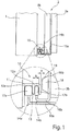
- the in Fig. 1 shown cabinet comprises a cabinet body 1 and a sliding door 2 with two sliding in parallel planes door 3a, 3b for closing a cabinet opening.
- the two door leaves 3a, 3b are above each an upper guide fitting (not shown) in the front and in the rear guideway a body side, upper horizontal double rail (not shown) suspended and guided therein displaceable.
- a body side, lower guide rail 11 with a rear and front guide rail 12a, 12b, which are each open at the bottom and from each other by a Separating web 13 are separated, a fixed at the bottom of the front door 3a first guide fitting 14a and a bottom attached to the rear door leaf 3b second guide fitting 14b includes.
- the rear guide track 12a is wider than the front guide track 12b.
- the first guide fitting 14a has the shape of an angle, the vertical leg 15a is screwed to the lower end of the front door leaf 3a and its horizontal leg 16a engages with its vertically upwardly angled guide end 17a in the rear guide track 12a of the guide rail 11 and slidably guided therein , The leading end 17a is wider than the front guide track 12b so that it can not be inserted into the front guide track 12b.
- the guide element may be formed by a separate sliding element.
- the second guide fitting 14b also has the shape of an angle, the vertical leg 15b is screwed to the lower end of the rear door leaf 3b and the horizontal leg 16b engages with its vertically upwardly angled guide end 17b in the front guide rail 12b of the guide rail 11 and slidably guided therein is.
- the two guideways 12a, 12b lie closely behind each other and are separated from each other only by the narrow web 13 and because the horizontal leg 16b must have a sufficient length so that the rear door 3b is kept at a certain distance from the guide rail 11, when hanging of the rear door leaf 3b, the leading end 17b is inadvertently inserted into the rear guide track 12a.
- the second guide fitting 14b - in the illustrated embodiment its vertical Leg 15b - over the rear of the rear door leaf 3b to the rear projecting projection 18 which is located at its lower end at the level of the leading end 17b and extends with its upper end to above the guide end 17b.
- the projection 18 protrudes so far that in the mounted state, the horizontal distance A remaining between the projection 18 and the front side of the guide rail 11 is smaller than the total width B of the separating web 13 and the guide end 17b of the second guide fitting 14b.
- the horizontal distance A of the projection 18 to the front of the guide rail 11 is greater than the guide clearance of the guide end 17b guided in the front guide track 12b, so that the projection 18 has no contact with the guide rail 11, and is preferably about half the web width the front guideway 12b.
- the projection 18 may be formed, for example, by a bulge of the vertical leg 15b.
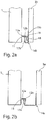
- the rear door leaf 3b is brought closer to the guide rail 11 in a position lowered relative to the assembled end position, until either the projection 18, as in FIG Fig. 2a shown, or the above the projection 18 located vertical leg 15 b at the front of the guide rail 11 abuts.
- the leading end 17b is located immediately below the front guide track 12b and is inserted into the front guide track 12b by lifting the rear door leaf 3b.
- the protrusion 18 with its oblique upper surface 19 projects on the lower edge of the guide rail 11, whereby the rear door leaf 3b is moved away from the guide rail 11 until the protrusion 18, as in FIG Fig. 2a shown finally abuts the front of the guide rail 11, and the leading end 17b is introduced by further lifting the rear door leaf 3b in the front guide rail 12b.
- Accidental insertion of the guide end 17b in the rear guide track 12a is excluded by the projection 18.
- the leading end 17a of the first guide bracket 14a can not be inserted into the front guide track 12b because it is wider than the front guide track 12b be like in Fig. 2b is shown, but only in the rear guide track 12a.
- the guide device 10 thus ensures the correct insertion of the two guide fittings 14a, 14b into their respective guide track 12a, 12b.
- Guide device 10 shown does not have the projection 18, so that here only the accidental insertion of the wider guide end 17a is prevented in the narrower front guide rail 12b.
- the rear guide track 12a narrower than the front guide track 12b and correspondingly the leading end 17a of the first guide fitting 14a may be made narrower than the leading end 17b of the second guide fitting 14b so as to inadvertently insert the wider guide end 17b into the narrower rear guide track 12a prevent.
Landscapes
- Engineering & Computer Science (AREA)
- Mechanical Engineering (AREA)
- Support Devices For Sliding Doors (AREA)
- Wing Frames And Configurations (AREA)
Description
- Die Erfindung betrifft eine Führungsvorrichtung für eine Schiebetür mit zwei in parallelen Ebenen schiebbaren Türflügeln aufweisend eine korpusseitige, untere Führungsschiene mit einer hinteren und vorderen Führungsbahn, die jeweils nach unten offen sind und voneinander durch einen Trennsteg getrennt sind, einen am vorderen Türflügel befestigbaren ersten Führungsbeschlag, der einen nach hinten abstehenden Schenkel mit einem vertikal nach oben abgewinkelten Führungsende aufweist, welches im montierten Zustand in der hinteren Führungsbahn verschiebbar geführt ist, und einen am hinteren Türflügel befestigbaren zweiten Führungsbeschlag, der einen vertikalen Schenkel zum Befestigen am hinteren Türflügel und einen nach hinten abstehenden Schenkel mit einem vertikal nach oben abgewinkelten Führungsende aufweist, welches im montierten Zustand in der vorderen Führungsbahn verschiebbar geführt ist.
- Eine derartige Führungsvorrichtung ist beispielsweise durch die
DE 20 2012 001 115 U1 bekannt. - Bei dieser bekannten Führungsvorrichtung sind die beiden Führungsbahnen und somit auch die beiden Führungsenden jeweils gleichbreit ausgeführt. Beim Einhängen der beiden Türflügel besteht daher die Gefahr, dass versehentlich ein Türflügel mit seinem Führungsende in die falsche Führungsbahn eingeführt wird. Da dies dann meist erst beim erstmaligen Verschieben der beiden Türflügel festgestellt wird, muss der betroffene Türflügel zunächst vollständig ausgehängt werden, bevor er mit seinem Führungsende in die richtige Führungsbahn eingeführt werden kann.
- Demgegenüber ist es die Aufgabe der vorliegenden Erfindung, bei einer Führungsvorrichtung der eingangs genannten Art das versehentliche Einführen eines Führungsendes in die falsche Führungsbahn sicher auszuschließen.
- Diese Aufgabe wird erfindungsgemäß dadurch gelöst, dass der vertikale Schenkel des zweiten Führungsbeschlags einen nach hinten vorstehenden Vorsprung aufweist, der sich zumindest unmittelbar oberhalb des Führungsendes erstreckt und dessen horizontaler Abstand zur Vorderseite der Führungsschiene im montierten Zustand kleiner als die Gesamtbreite des Trennstegs und des Führungsendes des zweiten Führungsbeschlags ist.
- Der erfindungsgemäße Vorsprung stellt also eine Vertauschsicherung dar, die ein versehentliches Einführen des Führungsendes des hinteren Türflügels in die für den vorderen Türflügel vorgesehene hintere Führungsbahn ausschließt.
- Bevorzugt entspricht im montierten Zustand der horizontale Abstand des Vorsprungs zur Vorderseite der Führungsschiene mindestens dem Führungsspiel des in der vorderen Führungsbahn geführten Führungsendes, damit der Vorsprung keine Berührung mehr mit der Führungsschiene hat. Besonders bevorzugt entspricht der horizontale Abstand etwa der halben Bahnbreite der vorderen Führungsbahn. In beiden Fällen kann das Führungsende des hinteren Türflügels, wenn der Vorsprung an der Führungsschiene anliegt, durch Anheben des Türflügels in die vordere Führungsbahn eingeführt werden.
Vorzugsweise aufweist der Vorsprung eine in Richtung auf das Führungsende des zweiten Führungsbeschlags schräg nach unten gerichtete Oberseite auf. Diese Maßnahme hat den Vorteil, dass, wenn beim Annähern an die Führungsschiene der hintere Türflügel nicht mit dem Vorsprung, sondern mit dem darüber befindlichen vertikalen Schenkel an der Vorderseite der Führungsschiene anschlägt, durch Anheben des hinteren Türflügels der Vorsprung mit seiner schrägen Oberseite zunächst an der Unterkante der Führungsschiene entlanggleitet, bis schließlich an der Vorderseite der Führungsschiene anliegt, und danach das Führungsende in die vordere Führungsbahn eingeführt wird.
Damit beim Anheben des hinteren Türflügels der Vorsprung möglichst lange an der Vorderseite der Führungsschiene gleitet, erstreckt sich der Vorsprung bevorzugt nach unten bis mindestens auf die Höhe des Führungsendes des zweiten Führungsbeschlags.
Besonders bevorzugt ist die hintere Führungsbahn breiter als die vordere Führungsbahn und das Führungsende des ersten Führungsbeschlags breiter als die vordere Führungsbahn. Das Führungsende des vorderen Türflügels kann, da es breiter als die vordere Führungsbahn ist, nicht in die vordere Führungsbahn, sondern nur in die hintere Führungsbahn eingeführt werden, wodurch auch für den vorderen Türflügel eine Vertauschsicherung gegeben ist.
Die oben genannte Aufgabe wird erfindungsgemäß auch dadurch gelöst, dass die Führungsbahnen unterschiedlich breit sind und das Führungsende eines der beiden Führungsbeschläge breiter als die schmalere der beiden Führungsbahnen ist. Vorzugsweise ist dabei die vordere Führungsbahn schmaler als die hintere Führungsbahn. Auf diese Weise kann das versehentliche Einführen des breiteren Führungsendes in die schmalere, fasche Führungsbahn verhindert werden. - Besonders vorteilhaft sind die Führungsenden der Führungsbeschläge jeweils durch ein separates Gleitelement gebildet, um die Gleiteigenschaften der Führungsenden innerhalb der Führungsbahnen zu verbessern.
- Die Erfindung betrifft schließlich auch eine Schiebetür mit zwei in parallelen Ebenen schiebbaren Türflügeln und mit einer wie oben ausgebildeten Führungsvorrichtung.
- Weitere Vorteile der Erfindung ergeben sich aus der Beschreibung, den Ansprüchen und der Zeichnung. Ebenso können die vorstehend genannten und die noch weiter aufgeführten Merkmale je für sich oder zu mehreren in beliebigen Kombinationen Verwendung finden. Die gezeigten und beschriebenen Ausführungsformen sind nicht als abschließende Aufzählung zu verstehen, sondern haben vielmehr beispielhaften Charakter für die Schilderung der Erfindung.
- Es zeigen:
- Fig. 1
- eine Seitenansicht einer erfindungsgemäßen Führungsvorrichtung für eine Schiebetür mit zwei in parallelen Ebenen schiebbaren Türflügeln:
- Fign. 2a, 2b
- die Führungsvorrichtung von
Fig. 1 beim Einsetzen des hinteren Türflügels (Fig. 2a ) und des vorderen Türflügels (Fig. 2b ); und - Fign. 3, 4
- zwei weitere Ausführungsformen der erfindungsgemäßen Führungsvorrichtung für eine Schiebetür mit zwei in parallelen Ebenen schiebbaren Türflügeln, jeweils in einer Seitenansicht.
- In der folgenden Figurenbeschreibung werden für gleiche bzw. funktionsgleiche Bauteile identische Bezugszeichen verwendet.
- Der in
Fig. 1 gezeigte Schrank umfasst einen Schrankkorpus 1 und eine Schiebetür 2 mit zwei in parallelen Ebenen schiebbaren Türflügel 3a, 3b zum Verschließen einer Schranköffnung. Die beiden Türflügel 3a, 3b sind oben jeweils über einen oberen Führungsbeschlag (nicht gezeigt) in der vorderen bzw. in der hinteren Führungsbahn einer korpusseitigen, oberen horizontalen Doppelschiene (nicht gezeigt) aufgehängt und darin verschiebbar geführt. - Zum Führen der unteren Enden der beiden Türflügel 3a, 3b beim Verschieben der Türflügel 3a, 3b dient eine Führungsvorrichtung 10, die eine korpusseitige, untere Führungsschiene 11 mit einer hinteren und vorderen Führungsbahn 12a, 12b, welche jeweils nach unten offen sind und voneinander durch einen Trennsteg 13 getrennt sind, einen unten am vorderen Türflügel 3a befestigten ersten Führungsbeschlag 14a und einen unten am hinteren Türflügel 3b befestigten zweiten Führungsbeschlag 14b umfasst. Die hintere Führungsbahn 12a ist breiter als die vordere Führungsbahn 12b.
- Der erste Führungsbeschlag 14a hat die Form eines Winkels, dessen vertikaler Schenkel 15a am unteren Ende des vorderen Türflügels 3a angeschraubt ist und dessen horizontaler Schenkel 16a mit seinem vertikal nach oben abgewinkelten Führungsende 17a in die hintere Führungsbahn 12a der Führungsschiene 11 eingreift und darin verschiebbar geführt ist. Das Führungsende 17a ist breiter als die vordere Führungsbahn 12b, so dass es nicht in die vordere Führungsbahn 12b eingeführt werden kann. Das Führungselement kann durch ein separates Gleitelement gebildet sein.
- Der zweite Führungsbeschlag 14b hat ebenfalls die Form eines Winkels, dessen vertikaler Schenkel 15b am unteren Ende des hinteren Türflügels 3b angeschraubt ist und dessen horizontaler Schenkel 16b mit seinem vertikal nach oben abgewinkelten Führungsende 17b in die vordere Führungsbahn 12b der Führungsschiene 11 eingreift und darin verschiebbar geführt ist.
- Weil die beiden Führungsbahnen 12a, 12b dicht hintereinander liegen und nur durch den schmalen Steg 13 voneinander getrennt sind und weil der waagerechte Schenkel 16b eine ausreichende Länge aufweisen muss, damit der hintere Türflügel 3b in einem gewissen Abstand zur Führungsschiene 11 gehalten wird, kann beim Einhängen des hinteren Türflügels 3b das Führungsende 17b versehentlich in die hintere Führungsbahn 12a einführt werden. Um dies zu verhindern, weist der zweite Führungsbeschlag 14b - im gezeigten Ausführungsbeispiel sein vertikaler Schenkel 15b - einen über die Rückseite des hinteren Türflügels 3b nach hinten vorstehenden Vorsprung 18 auf, der sich mit seinem unteren Ende auf Höhe des Führungsendes 17b befindet und mit seinem oberen Ende bis oberhalb des Führungsendes 17b erstreckt. Der Vorsprung 18 steht so weit vor, dass im montierten Zustand der zwischen dem Vorsprung 18 und der Vorderseite der Führungsschiene 11 verbleibende horizontale Abstand A kleiner ist als die Gesamtbreite B des Trennstegs 13 und des Führungsendes 17b des zweiten Führungsbeschlags 14b. Im montierten Zustand ist der horizontale Abstand A des Vorsprungs 18 zur Vorderseite der Führungsschiene 11 größer als das Führungsspiel des in der vorderen Führungsbahn 12b geführten Führungsendes 17b, damit der Vorsprung 18 keine Berührung mehr mit der Führungsschiene 11 hat, und beträgt vorzugsweise etwa die halbe Bahnbreite der vorderen Führungsbahn 12b. Der Vorsprung 18 kann beispielsweise durch eine Ausbauchung des vertikalen Schenkels 15b gebildet sein.
- Zum Einführen des zweiten Führungsbeschlags 14b in die vordere Führungsbahn 12b wird der hintere Türflügel 3b in einer gegenüber der montierten Endlage abgesenkten Lage an die Führungsschiene 11 angenähert, bis entweder der Vorsprung 18, wie in
Fig. 2a gezeigt, oder der oberhalb des Vorsprungs 18 befindliche vertikale Schenkel 15b an der Vorderseite der Führungsschiene 11 anschlägt. Im ersteren Fall befindet sich das Führungsende 17b unmittelbar unterhalb der vorderen Führungsbahn 12b und wird durch Anheben des hinteren Türflügels 3b in die vordere Führungsbahn 12b eingeführt. Im zweiten Fall läuft durch Anheben des hinteren Türflügels 3b der Vorsprung 18 mit seiner schrägen Oberseite 19 auf die Unterkante der Führungsschiene 11 auf, wodurch der hintere Türflügel 3b von der Führungsschiene 11 wegbewegt wird, bis der Vorsprung 18, wie inFig. 2a gezeigt, schließlich an der Vorderseite der Führungsschiene 11 anliegt, und das Führungsende 17b durch weiteres Anheben des hinteren Türflügels 3b in die vordere Führungsbahn 12b eingeführt wird. Ein versehentliches Einführen des Führungsendes 17b in die hintere Führungsbahn 12a ist durch den Vorsprung 18 ausgeschlossen. - Das Führungsende 17a des ersten Führungsbeschlags 14a kann, da es breiter als die vordere Führungsbahn 12b ist, nicht in die vordere Führungsbahn 12b eingeführt werden, wie in
Fig. 2b gezeigt ist, sondern nur in die hintere Führungsbahn 12a. Durch die Führungsvorrichtung 10 ist somit das korrekte Einführen der beiden Führungsbeschläge 14a, 14b in ihre jeweilige Führungsbahn 12a, 12b sichergestellt. - Im Unterschied zur Führungsvorrichtung der
Fign. 1 und2 weist die inFig. 3 gezeigte Führungsvorrichtung 10 den Vorsprung 18 nicht auf, so dass hier lediglich das versehentliche Einführen des breiteren Führungsendes 17a in die schmalere vordere Führungsbahn 12b verhindert ist. Alternativ kann auch die hintere Führungsbahn 12a schmaler als die vordere Führungsbahn 12b und entsprechend das Führungsende 17a des ersten Führungsbeschlags 14a schmaler als das Führungsende 17b des zweiten Führungsbeschlags 14b ausgeführt sein, um so das versehentliche Einführen des breiteren Führungsendes 17b in die schmalere hintere Führungsbahn 12a zu verhindern. - Im Unterschied zur Führungsvorrichtung der
Fign. 1 und2 sind bei der inFig. 4 gezeigten Führungsvorrichtung 10 die beiden Führungsbahnen 12a, 12b und somit auch die beiden Führungsenden 17a, 17b jeweils gleichbreit ausgeführt, so dass hier lediglich das versehentliche Einführen des Führungsendes 17b in die hintere Führungsbahn 12a durch den Vorsprung 18 verhindert ist.
Claims (10)
- Führungsvorrichtung (10) für eine Schiebetür (2) mit zwei in parallelen Ebenen schiebbaren Türflügeln (3a, 3b), aufweisend:- eine korpusseitige, untere Führungsschiene (11) mit einer hinteren und vorderen Führungsbahn (12a, 12b), die jeweils nach unten offen sind und voneinander durch einen Trennsteg (13) getrennt sind,- einen am vorderen Türflügel (3a) befestigbaren ersten Führungsbeschlag (14a), der einen nach hinten abstehenden Schenkel (16a) mit einem vertikal nach oben abgewinkelten Führungsende (17a) aufweist, welches im montierten Zustand in der hinteren Führungsbahn (12a) verschiebbar geführt ist, und- einen am hinteren Türflügel (3b) befestigbaren zweiten Führungsbeschlag (14b), der einen vertikalen Schenkel (15b) zum Befestigen am hinteren Türflügel (3b) und einen nach hinten abstehenden Schenkel (16b) mit einem vertikal nach oben abgewinkelten Führungsende (17b) aufweist, welches im montierten Zustand in der vorderen Führungsbahn (12b) verschiebbar geführt ist,dadurch gekennzeichnet,
dass der vertikale Schenkel (15b) des zweiten Führungsbeschlags (14b) einen nach hinten vorstehenden Vorsprung (18) aufweist, der sich zumindest unmittelbar oberhalb des Führungsendes (17b) erstreckt und dessen horizontaler Abstand (A) zur Vorderseite der Führungsschiene (11) im montierten Zustand kleiner als die Gesamtbreite (B) des Trennstegs (13) und des Führungsendes (17b) des zweiten Führungsbeschlags (14b) ist. - Führungsvorrichtung nach Anspruch 1, dadurch gekennzeichnet, dass im montierten Zustand der horizontale Abstand (A) des Vorsprungs (18) zur Vorderseite der Führungsschiene (11) mindestens dem Führungsspiel des in der vorderen Führungsbahn (12b) geführten Führungsendes (17b) entspricht.
- Führungsvorrichtung nach Anspruch 1 oder 2, dadurch gekennzeichnet, dass im montierten Zustand der horizontale Abstand (A) des Vorsprungs (18) zur Vorderseite der Führungsschiene (11) etwa der halben Bahnbreite der vorderen Führungsbahn (12b) entspricht.
- Führungsvorrichtung nach einem der vorhergehenden Ansprüche, dadurch gekennzeichnet, dass der Vorsprung (18) eine in Richtung auf das Führungsende (17b) des zweiten Führungsbeschlags (14b) schräg nach unten gerichtete Oberseite (19) aufweist.
- Führungsvorrichtung nach einem der vorhergehenden Ansprüche, dadurch gekennzeichnet, dass sich der Vorsprung (18) nach unten bis mindestens auf die Höhe des Führungsendes (17b) des zweiten Führungsbeschlags (14b) erstreckt.
- Führungsvorrichtung nach einem der vorhergehenden Ansprüche, dadurch gekennzeichnet, dass die hintere Führungsbahn (12a) breiter als die vordere Führungsbahn (12b) ist und das Führungsende (17a) des ersten Führungsbeschlags (14a) breiter als die vordere Führungsbahn (12b) ist.
- Führungsvorrichtung (10) für eine Schiebetür (2) mit zwei in parallelen Ebenen schiebbaren Türflügeln (3a, 3b), aufweisend:- eine korpusseitige, untere Führungsschiene (11) mit einer hinteren und vorderen Führungsbahn (12a, 12b), die jeweils nach unten offen sind und voneinander durch einen Trennsteg (13) getrennt sind,- einen am vorderen Türflügel (3a) befestigbaren ersten Führungsbeschlag (14a), der einen nach hinten abstehenden Schenkel (16a) mit einem vertikal nach oben abgewinkelten Führungsende (17a) aufweist, welches im montierten Zustand in der hinteren Führungsbahn (12a) verschiebbar geführt ist, und- einen am hinteren Türflügel (3b) befestigbaren zweiten Führungsbeschlag (14b), der einen nach hinten abstehenden Schenkel (16b) mit einem vertikal nach oben abgewinkelten Führungsende (17b) aufweist, welches im montierten Zustand in der vorderen Führungsbahn (12b) verschiebbar geführt ist,dadurch gekennzeichnet,
dass die Führungsbahnen (12a, 12b) unterschiedlich breit sind und das Führungsende (17a) eines der beiden Führungsbeschläge (14a, 14b) breiter als die schmalere der beiden Führungsbahnen (12a, 12b) ist. - Führungsvorrichtung nach Anspruch 7, dadurch gekennzeichnet, dass die vordere Führungsbahn (12b) schmaler als die hintere Führungsbahn (12a) ist.
- Führungsvorrichtung nach einem der vorhergehenden Ansprüche, dadurch gekennzeichnet, dass die Führungsenden (17a, 17b) der Führungsbeschläge (14a, 14b) jeweils durch ein separates Gleitelement gebildet sind.
- Schiebetür (2) mit zwei in parallelen Ebenen schiebbaren Türflügeln (3a, 3b) und mit einer Führungsvorrichtung (10) nach einem der vorhergehenden Ansprüche.
Priority Applications (1)
| Application Number | Priority Date | Filing Date | Title |
|---|---|---|---|
| PL15186782T PL3009587T3 (pl) | 2014-10-16 | 2015-09-25 | Mechanizm prowadzący dla drzwi przesuwnych z dwoma przesuwnymi w równoległych płaszczyznach skrzydłami drzwiowymi |
Applications Claiming Priority (1)
| Application Number | Priority Date | Filing Date | Title |
|---|---|---|---|
| DE202014104927.4U DE202014104927U1 (de) | 2014-10-16 | 2014-10-16 | Führungsvorrichtung für eine Schiebetür mit zwei in parallelen Ebenen schiebbaren Türflügeln |
Publications (2)
| Publication Number | Publication Date |
|---|---|
| EP3009587A1 EP3009587A1 (de) | 2016-04-20 |
| EP3009587B1 true EP3009587B1 (de) | 2017-11-08 |
Family
ID=51900013
Family Applications (1)
| Application Number | Title | Priority Date | Filing Date |
|---|---|---|---|
| EP15186782.7A Active EP3009587B1 (de) | 2014-10-16 | 2015-09-25 | Führungsvorrichtung für eine schiebetür mit zwei in parallelen ebenen schiebbaren türflügeln |
Country Status (6)
| Country | Link |
|---|---|
| EP (1) | EP3009587B1 (de) |
| CN (2) | CN109882011A (de) |
| DE (1) | DE202014104927U1 (de) |
| DK (1) | DK3009587T3 (de) |
| ES (1) | ES2659187T3 (de) |
| PL (1) | PL3009587T3 (de) |
Families Citing this family (2)
| Publication number | Priority date | Publication date | Assignee | Title |
|---|---|---|---|---|
| DE202014104927U1 (de) * | 2014-10-16 | 2014-10-28 | Weber & Co. Gmbh Kg | Führungsvorrichtung für eine Schiebetür mit zwei in parallelen Ebenen schiebbaren Türflügeln |
| DE202019103293U1 (de) | 2019-06-12 | 2019-06-18 | Häfele GmbH & Co KG | Führungsvorrichtung für eine Schiebetür mit zwei in parallelen Ebenen schiebbaren Türflügeln |
Family Cites Families (12)
| Publication number | Priority date | Publication date | Assignee | Title |
|---|---|---|---|---|
| FR2005911A1 (de) * | 1968-04-10 | 1969-12-19 | Brigfon Sas Fontanesi | |
| AT325241B (de) * | 1974-01-22 | 1975-10-10 | Team Form Ag | Führungsschienen für schrankschiebetüren |
| DE3147061A1 (de) * | 1981-11-27 | 1983-06-09 | Heinz Georg 3626 Hünibach Thun Baus | Vorrichtung mit einer schiebetuer |
| SE8902221L (sv) * | 1989-06-20 | 1990-12-21 | Electrolux Ab | Anordning vid skjutluckor foer skaap |
| CH684777A5 (de) * | 1992-12-29 | 1994-12-30 | Eku Ag | Laufwerksanordnung mit Rollen für eine Schiebetür. |
| JP3014277B2 (ja) * | 1994-06-29 | 2000-02-28 | オーリス株式会社 | 引き違い扉の吊下案内装置 |
| ITBL20060032A1 (it) * | 2006-10-18 | 2008-04-19 | Bortoluzzi Mobili Srl | Maschera ribassabile per la copertura dei dispositivi di sostegno delle ante scorrevoli di mobili |
| KR200442346Y1 (ko) * | 2007-09-12 | 2008-10-31 | 주식회사 코파산업 | 장롱의 슬라이딩 도어 이탈방지장치 |
| DE102011050395A1 (de) * | 2011-05-17 | 2012-11-22 | Hettich-Heinze Gmbh & Co. Kg | Beschlag für eine Schiebetür |
| DE202012001115U1 (de) * | 2012-02-06 | 2012-03-12 | Günther Zimmer | Schiebetürschrank mit mindestens drei Türblättern |
| HK1209809A1 (en) * | 2012-06-25 | 2016-04-08 | 哈多高级设计与技术有限公司 | Engagement mechanism for engaging roller with lower track of sliding door |
| DE202014104927U1 (de) * | 2014-10-16 | 2014-10-28 | Weber & Co. Gmbh Kg | Führungsvorrichtung für eine Schiebetür mit zwei in parallelen Ebenen schiebbaren Türflügeln |
-
2014
- 2014-10-16 DE DE202014104927.4U patent/DE202014104927U1/de not_active Expired - Lifetime
-
2015
- 2015-09-25 DK DK15186782.7T patent/DK3009587T3/en active
- 2015-09-25 EP EP15186782.7A patent/EP3009587B1/de active Active
- 2015-09-25 PL PL15186782T patent/PL3009587T3/pl unknown
- 2015-09-25 ES ES15186782.7T patent/ES2659187T3/es active Active
- 2015-10-14 CN CN201811425068.9A patent/CN109882011A/zh active Pending
- 2015-10-14 CN CN201510661539.6A patent/CN105525815B/zh active Active
Non-Patent Citations (1)
| Title |
|---|
| None * |
Also Published As
| Publication number | Publication date |
|---|---|
| CN105525815B (zh) | 2018-11-27 |
| PL3009587T3 (pl) | 2018-05-30 |
| CN109882011A (zh) | 2019-06-14 |
| DK3009587T3 (en) | 2018-02-05 |
| CN105525815A (zh) | 2016-04-27 |
| EP3009587A1 (de) | 2016-04-20 |
| DE202014104927U1 (de) | 2014-10-28 |
| ES2659187T3 (es) | 2018-03-14 |
Similar Documents
| Publication | Publication Date | Title |
|---|---|---|
| EP1080290B1 (de) | Puffervorrichtung | |
| EP3358115B1 (de) | Einzugsdämpferbeschlag für eine schiebetür und zugehöriges montageverfahren | |
| DE112016001573T5 (de) | Verbessertes scharnier für eine möbeltür | |
| DE102017000214A1 (de) | Verschlussanordnung, insbesondere für Schrankmöbel | |
| EP2405095B1 (de) | Türdichtung mit Befestigungselement | |
| EP3009587A1 (de) | Führungsvorrichtung für eine schiebetür mit zwei in parallelen ebenen schiebbaren türflügeln | |
| EP4019724B1 (de) | Beschlag zur befestigung einer geteilten laufschiene an einem schiebetürschrank und zugehöriger schiebetürschrank | |
| EP3192957B1 (de) | Vorrichtung zur bildung eines wandanschlusses | |
| EP3055475A1 (de) | Schiebetür oder schiebefenster | |
| EP3094803B1 (de) | Schiebetüranordnung mit in einer gemeinsamen ebene angeordneten schiebeflügeln | |
| EP2859170A1 (de) | Rollladenschrank | |
| DE102012200430B4 (de) | Schiebetüren- oder -fensteranlage mit mindestens zwei als Tür oder Fenster ausgebildeten Schiebeelementen sowie Verriegelungseinrichtung hierfür | |
| CH715007B1 (de) | Schubladenauszug mit Auszugsbegrenzung. | |
| DE202017006165U1 (de) | Rollladenkasten mit in Breitenrichtung verstellbarem Führungsprofil | |
| DE102022104280B4 (de) | Haushaltsgerät, insbesondere Geschirrspülmaschine | |
| DE202018106882U1 (de) | Anbaueinrichtung für Vorhangschienen und Vorhangsystem | |
| EP2764809B1 (de) | Duschabtrennung | |
| EP2784262B1 (de) | Schrank mit Rollo | |
| DE10050176B4 (de) | Einrastbare Führungsschiene | |
| DE202016008096U1 (de) | Gebäudeabschlussantriebsvorrichtung | |
| DE202004007227U1 (de) | Schubladenführung | |
| EP3348775B1 (de) | Fingerschutzvorrichtung an einer nebenschliesskante eines tür- oder fensterflügels | |
| EP3015627B1 (de) | Rastvorrichtung für ein fenster oder eine tür | |
| EP2604777B1 (de) | Schließleiste | |
| DE202015106076U1 (de) | Scharnier für Schrank mit Rahmenprofilen |
Legal Events
| Date | Code | Title | Description |
|---|---|---|---|
| PUAI | Public reference made under article 153(3) epc to a published international application that has entered the european phase |
Free format text: ORIGINAL CODE: 0009012 |
|
| AK | Designated contracting states |
Kind code of ref document: A1 Designated state(s): AL AT BE BG CH CY CZ DE DK EE ES FI FR GB GR HR HU IE IS IT LI LT LU LV MC MK MT NL NO PL PT RO RS SE SI SK SM TR |
|
| AX | Request for extension of the european patent |
Extension state: BA ME |
|
| 17P | Request for examination filed |
Effective date: 20160330 |
|
| RBV | Designated contracting states (corrected) |
Designated state(s): AL AT BE BG CH CY CZ DE DK EE ES FI FR GB GR HR HU IE IS IT LI LT LU LV MC MK MT NL NO PL PT RO RS SE SI SK SM TR |
|
| GRAP | Despatch of communication of intention to grant a patent |
Free format text: ORIGINAL CODE: EPIDOSNIGR1 |
|
| INTG | Intention to grant announced |
Effective date: 20170403 |
|
| RAP1 | Party data changed (applicant data changed or rights of an application transferred) |
Owner name: SLIDING COMPETENCE CENTER KFT. |
|
| GRAS | Grant fee paid |
Free format text: ORIGINAL CODE: EPIDOSNIGR3 |
|
| GRAA | (expected) grant |
Free format text: ORIGINAL CODE: 0009210 |
|
| AK | Designated contracting states |
Kind code of ref document: B1 Designated state(s): AL AT BE BG CH CY CZ DE DK EE ES FI FR GB GR HR HU IE IS IT LI LT LU LV MC MK MT NL NO PL PT RO RS SE SI SK SM TR |
|
| REG | Reference to a national code |
Ref country code: GB Ref legal event code: FG4D Free format text: NOT ENGLISH |
|
| REG | Reference to a national code |
Ref country code: CH Ref legal event code: EP Ref country code: AT Ref legal event code: REF Ref document number: 944323 Country of ref document: AT Kind code of ref document: T Effective date: 20171115 |
|
| REG | Reference to a national code |
Ref country code: IE Ref legal event code: FG4D Free format text: LANGUAGE OF EP DOCUMENT: GERMAN |
|
| REG | Reference to a national code |
Ref country code: DE Ref legal event code: R096 Ref document number: 502015002295 Country of ref document: DE |
|
| REG | Reference to a national code |
Ref country code: DK Ref legal event code: T3 Effective date: 20180130 |
|
| REG | Reference to a national code |
Ref country code: SE Ref legal event code: TRGR |
|
| REG | Reference to a national code |
Ref country code: NL Ref legal event code: FP |
|
| REG | Reference to a national code |
Ref country code: ES Ref legal event code: FG2A Ref document number: 2659187 Country of ref document: ES Kind code of ref document: T3 Effective date: 20180314 |
|
| REG | Reference to a national code |
Ref country code: LT Ref legal event code: MG4D |
|
| PG25 | Lapsed in a contracting state [announced via postgrant information from national office to epo] |
Ref country code: LT Free format text: LAPSE BECAUSE OF FAILURE TO SUBMIT A TRANSLATION OF THE DESCRIPTION OR TO PAY THE FEE WITHIN THE PRESCRIBED TIME-LIMIT Effective date: 20171108 Ref country code: FI Free format text: LAPSE BECAUSE OF FAILURE TO SUBMIT A TRANSLATION OF THE DESCRIPTION OR TO PAY THE FEE WITHIN THE PRESCRIBED TIME-LIMIT Effective date: 20171108 Ref country code: NO Free format text: LAPSE BECAUSE OF FAILURE TO SUBMIT A TRANSLATION OF THE DESCRIPTION OR TO PAY THE FEE WITHIN THE PRESCRIBED TIME-LIMIT Effective date: 20180208 |
|
| PG25 | Lapsed in a contracting state [announced via postgrant information from national office to epo] |
Ref country code: GR Free format text: LAPSE BECAUSE OF FAILURE TO SUBMIT A TRANSLATION OF THE DESCRIPTION OR TO PAY THE FEE WITHIN THE PRESCRIBED TIME-LIMIT Effective date: 20180209 Ref country code: RS Free format text: LAPSE BECAUSE OF FAILURE TO SUBMIT A TRANSLATION OF THE DESCRIPTION OR TO PAY THE FEE WITHIN THE PRESCRIBED TIME-LIMIT Effective date: 20171108 Ref country code: BG Free format text: LAPSE BECAUSE OF FAILURE TO SUBMIT A TRANSLATION OF THE DESCRIPTION OR TO PAY THE FEE WITHIN THE PRESCRIBED TIME-LIMIT Effective date: 20180208 Ref country code: HR Free format text: LAPSE BECAUSE OF FAILURE TO SUBMIT A TRANSLATION OF THE DESCRIPTION OR TO PAY THE FEE WITHIN THE PRESCRIBED TIME-LIMIT Effective date: 20171108 Ref country code: IS Free format text: LAPSE BECAUSE OF FAILURE TO SUBMIT A TRANSLATION OF THE DESCRIPTION OR TO PAY THE FEE WITHIN THE PRESCRIBED TIME-LIMIT Effective date: 20180308 Ref country code: LV Free format text: LAPSE BECAUSE OF FAILURE TO SUBMIT A TRANSLATION OF THE DESCRIPTION OR TO PAY THE FEE WITHIN THE PRESCRIBED TIME-LIMIT Effective date: 20171108 |
|
| PG25 | Lapsed in a contracting state [announced via postgrant information from national office to epo] |
Ref country code: SK Free format text: LAPSE BECAUSE OF FAILURE TO SUBMIT A TRANSLATION OF THE DESCRIPTION OR TO PAY THE FEE WITHIN THE PRESCRIBED TIME-LIMIT Effective date: 20171108 Ref country code: CY Free format text: LAPSE BECAUSE OF FAILURE TO SUBMIT A TRANSLATION OF THE DESCRIPTION OR TO PAY THE FEE WITHIN THE PRESCRIBED TIME-LIMIT Effective date: 20171108 Ref country code: EE Free format text: LAPSE BECAUSE OF FAILURE TO SUBMIT A TRANSLATION OF THE DESCRIPTION OR TO PAY THE FEE WITHIN THE PRESCRIBED TIME-LIMIT Effective date: 20171108 Ref country code: CZ Free format text: LAPSE BECAUSE OF FAILURE TO SUBMIT A TRANSLATION OF THE DESCRIPTION OR TO PAY THE FEE WITHIN THE PRESCRIBED TIME-LIMIT Effective date: 20171108 |
|
| REG | Reference to a national code |
Ref country code: DE Ref legal event code: R097 Ref document number: 502015002295 Country of ref document: DE |
|
| PG25 | Lapsed in a contracting state [announced via postgrant information from national office to epo] |
Ref country code: RO Free format text: LAPSE BECAUSE OF FAILURE TO SUBMIT A TRANSLATION OF THE DESCRIPTION OR TO PAY THE FEE WITHIN THE PRESCRIBED TIME-LIMIT Effective date: 20171108 Ref country code: SM Free format text: LAPSE BECAUSE OF FAILURE TO SUBMIT A TRANSLATION OF THE DESCRIPTION OR TO PAY THE FEE WITHIN THE PRESCRIBED TIME-LIMIT Effective date: 20171108 |
|
| PLBE | No opposition filed within time limit |
Free format text: ORIGINAL CODE: 0009261 |
|
| STAA | Information on the status of an ep patent application or granted ep patent |
Free format text: STATUS: NO OPPOSITION FILED WITHIN TIME LIMIT |
|
| REG | Reference to a national code |
Ref country code: FR Ref legal event code: PLFP Year of fee payment: 4 |
|
| PG25 | Lapsed in a contracting state [announced via postgrant information from national office to epo] |
Ref country code: MT Free format text: LAPSE BECAUSE OF FAILURE TO SUBMIT A TRANSLATION OF THE DESCRIPTION OR TO PAY THE FEE WITHIN THE PRESCRIBED TIME-LIMIT Effective date: 20171108 |
|
| 26N | No opposition filed |
Effective date: 20180809 |
|
| PG25 | Lapsed in a contracting state [announced via postgrant information from national office to epo] |
Ref country code: SI Free format text: LAPSE BECAUSE OF FAILURE TO SUBMIT A TRANSLATION OF THE DESCRIPTION OR TO PAY THE FEE WITHIN THE PRESCRIBED TIME-LIMIT Effective date: 20171108 |
|
| PG25 | Lapsed in a contracting state [announced via postgrant information from national office to epo] |
Ref country code: MC Free format text: LAPSE BECAUSE OF FAILURE TO SUBMIT A TRANSLATION OF THE DESCRIPTION OR TO PAY THE FEE WITHIN THE PRESCRIBED TIME-LIMIT Effective date: 20171108 |
|
| REG | Reference to a national code |
Ref country code: CH Ref legal event code: PL |
|
| REG | Reference to a national code |
Ref country code: BE Ref legal event code: MM Effective date: 20180930 |
|
| REG | Reference to a national code |
Ref country code: IE Ref legal event code: MM4A |
|
| PG25 | Lapsed in a contracting state [announced via postgrant information from national office to epo] |
Ref country code: LU Free format text: LAPSE BECAUSE OF NON-PAYMENT OF DUE FEES Effective date: 20180925 |
|
| PG25 | Lapsed in a contracting state [announced via postgrant information from national office to epo] |
Ref country code: IE Free format text: LAPSE BECAUSE OF NON-PAYMENT OF DUE FEES Effective date: 20180925 |
|
| PG25 | Lapsed in a contracting state [announced via postgrant information from national office to epo] |
Ref country code: LI Free format text: LAPSE BECAUSE OF NON-PAYMENT OF DUE FEES Effective date: 20180930 Ref country code: CH Free format text: LAPSE BECAUSE OF NON-PAYMENT OF DUE FEES Effective date: 20180930 Ref country code: BE Free format text: LAPSE BECAUSE OF NON-PAYMENT OF DUE FEES Effective date: 20180930 |
|
| PG25 | Lapsed in a contracting state [announced via postgrant information from national office to epo] |
Ref country code: PT Free format text: LAPSE BECAUSE OF FAILURE TO SUBMIT A TRANSLATION OF THE DESCRIPTION OR TO PAY THE FEE WITHIN THE PRESCRIBED TIME-LIMIT Effective date: 20171108 |
|
| PG25 | Lapsed in a contracting state [announced via postgrant information from national office to epo] |
Ref country code: HU Free format text: LAPSE BECAUSE OF FAILURE TO SUBMIT A TRANSLATION OF THE DESCRIPTION OR TO PAY THE FEE WITHIN THE PRESCRIBED TIME-LIMIT; INVALID AB INITIO Effective date: 20150925 Ref country code: MK Free format text: LAPSE BECAUSE OF NON-PAYMENT OF DUE FEES Effective date: 20171108 |
|
| PG25 | Lapsed in a contracting state [announced via postgrant information from national office to epo] |
Ref country code: AL Free format text: LAPSE BECAUSE OF FAILURE TO SUBMIT A TRANSLATION OF THE DESCRIPTION OR TO PAY THE FEE WITHIN THE PRESCRIBED TIME-LIMIT Effective date: 20171108 |
|
| REG | Reference to a national code |
Ref country code: AT Ref legal event code: MM01 Ref document number: 944323 Country of ref document: AT Kind code of ref document: T Effective date: 20200925 |
|
| PG25 | Lapsed in a contracting state [announced via postgrant information from national office to epo] |
Ref country code: AT Free format text: LAPSE BECAUSE OF NON-PAYMENT OF DUE FEES Effective date: 20200925 |
|
| P01 | Opt-out of the competence of the unified patent court (upc) registered |
Effective date: 20230630 |
|
| PGFP | Annual fee paid to national office [announced via postgrant information from national office to epo] |
Ref country code: DK Payment date: 20240920 Year of fee payment: 10 |
|
| PGFP | Annual fee paid to national office [announced via postgrant information from national office to epo] |
Ref country code: GB Payment date: 20240923 Year of fee payment: 10 |
|
| PGFP | Annual fee paid to national office [announced via postgrant information from national office to epo] |
Ref country code: FR Payment date: 20240930 Year of fee payment: 10 |
|
| PGFP | Annual fee paid to national office [announced via postgrant information from national office to epo] |
Ref country code: NL Payment date: 20240920 Year of fee payment: 10 |
|
| PGFP | Annual fee paid to national office [announced via postgrant information from national office to epo] |
Ref country code: SE Payment date: 20240923 Year of fee payment: 10 |
|
| PGFP | Annual fee paid to national office [announced via postgrant information from national office to epo] |
Ref country code: TR Payment date: 20240917 Year of fee payment: 10 |
|
| PGFP | Annual fee paid to national office [announced via postgrant information from national office to epo] |
Ref country code: ES Payment date: 20241018 Year of fee payment: 10 |
|
| PGFP | Annual fee paid to national office [announced via postgrant information from national office to epo] |
Ref country code: DE Payment date: 20250926 Year of fee payment: 11 |
|
| PGFP | Annual fee paid to national office [announced via postgrant information from national office to epo] |
Ref country code: PL Payment date: 20250811 Year of fee payment: 11 |
|
| PGFP | Annual fee paid to national office [announced via postgrant information from national office to epo] |
Ref country code: IT Payment date: 20250930 Year of fee payment: 11 |
|
| REG | Reference to a national code |
Ref country code: DK Ref legal event code: EBP Effective date: 20250930 |
|
| REG | Reference to a national code |
Ref country code: NL Ref legal event code: MM Effective date: 20251001 |