EP3008917B1 - Suspension element for suspending the diaphragm of a loudspeaker driver to the chassis thereof as well as driver and loudspeaker comprising the same - Google Patents
Suspension element for suspending the diaphragm of a loudspeaker driver to the chassis thereof as well as driver and loudspeaker comprising the same Download PDFInfo
- Publication number
- EP3008917B1 EP3008917B1 EP13737842.8A EP13737842A EP3008917B1 EP 3008917 B1 EP3008917 B1 EP 3008917B1 EP 13737842 A EP13737842 A EP 13737842A EP 3008917 B1 EP3008917 B1 EP 3008917B1
- Authority
- EP
- European Patent Office
- Prior art keywords
- sections
- suspension element
- curved
- diaphragm
- height
- Prior art date
- Legal status (The legal status is an assumption and is not a legal conclusion. Google has not performed a legal analysis and makes no representation as to the accuracy of the status listed.)
- Active
Links
- 239000000725 suspension Substances 0.000 title claims description 156
- 239000000463 material Substances 0.000 claims description 23
- 230000007704 transition Effects 0.000 claims description 11
- 230000001419 dependent effect Effects 0.000 claims 5
- 230000015572 biosynthetic process Effects 0.000 claims 1
- 238000005755 formation reaction Methods 0.000 claims 1
- 206010052904 Musculoskeletal stiffness Diseases 0.000 description 91
- 238000006073 displacement reaction Methods 0.000 description 39
- 230000000750 progressive effect Effects 0.000 description 19
- 230000000694 effects Effects 0.000 description 4
- 239000003292 glue Substances 0.000 description 2
- 238000004088 simulation Methods 0.000 description 2
- 230000009286 beneficial effect Effects 0.000 description 1
- 239000012141 concentrate Substances 0.000 description 1
- 230000008878 coupling Effects 0.000 description 1
- 238000010168 coupling process Methods 0.000 description 1
- 238000005859 coupling reaction Methods 0.000 description 1
- 230000005674 electromagnetic induction Effects 0.000 description 1
- 238000007689 inspection Methods 0.000 description 1
- 230000002787 reinforcement Effects 0.000 description 1
- 230000000630 rising effect Effects 0.000 description 1
- 230000035945 sensitivity Effects 0.000 description 1
Images


Classifications
-
- H—ELECTRICITY
- H04—ELECTRIC COMMUNICATION TECHNIQUE
- H04R—LOUDSPEAKERS, MICROPHONES, GRAMOPHONE PICK-UPS OR LIKE ACOUSTIC ELECTROMECHANICAL TRANSDUCERS; DEAF-AID SETS; PUBLIC ADDRESS SYSTEMS
- H04R7/00—Diaphragms for electromechanical transducers; Cones
- H04R7/16—Mounting or tensioning of diaphragms or cones
- H04R7/18—Mounting or tensioning of diaphragms or cones at the periphery
- H04R7/20—Securing diaphragm or cone resiliently to support by flexible material, springs, cords, or strands
-
- H—ELECTRICITY
- H04—ELECTRIC COMMUNICATION TECHNIQUE
- H04R—LOUDSPEAKERS, MICROPHONES, GRAMOPHONE PICK-UPS OR LIKE ACOUSTIC ELECTROMECHANICAL TRANSDUCERS; DEAF-AID SETS; PUBLIC ADDRESS SYSTEMS
- H04R2307/00—Details of diaphragms or cones for electromechanical transducers, their suspension or their manufacture covered by H04R7/00 or H04R31/003, not provided for in any of its subgroups
- H04R2307/204—Material aspects of the outer suspension of loudspeaker diaphragms
-
- H—ELECTRICITY
- H04—ELECTRIC COMMUNICATION TECHNIQUE
- H04R—LOUDSPEAKERS, MICROPHONES, GRAMOPHONE PICK-UPS OR LIKE ACOUSTIC ELECTROMECHANICAL TRANSDUCERS; DEAF-AID SETS; PUBLIC ADDRESS SYSTEMS
- H04R2307/00—Details of diaphragms or cones for electromechanical transducers, their suspension or their manufacture covered by H04R7/00 or H04R31/003, not provided for in any of its subgroups
- H04R2307/207—Shape aspects of the outer suspension of loudspeaker diaphragms
Definitions
- the present invention relates to sound reproduction.
- the invention relates to suspending a diaphragm of a loudspeaker driver.
- the invention relates to a loudspeaker suspension element according to the preamble portion of claim 1.
- Reciprocal drivers used in loudspeakers typically include a chassis, which forms the rigid mechanical framework for the driver, a vibrating diaphragm, which is driven axially by means of electromagnetic induction forces generated by alternating current, and a suspension element surrounding the diaphragm and elastically coupling it to the chassis. It is paramount that the movement of the diaphragm is precisely and accurately controlled, which is a matter of suspension element design. Ideally the movement of the diaphragm is linear, or in other words the diaphragm motion in the axial direction is directly proportional to the magnitude of the alternating current that is applied to the driver. If the movement of the diaphragm is non-linear then the sound becomes distorted.
- the aim is to provide a progressive suspension element with fairly constant stiffness for small displacements and a rapidly increasing stiffness for large displacements.
- an ideal progressive suspension element will add low amounts of non-linearity (distortion) to the motion of the diaphragm for small displacements whilst also protecting the driver from damage during large excursions.
- the surrounding suspension element of a loudspeaker driver is easier to design when the shape of the suspension element is essentially round in relation to the direction of movement of the driver diaphragm.
- the force exerted by the suspension element is usually equal and symmetrical at all locations around the perimeter of the suspension element.
- the cross-sectional profile of the suspension element has the same geometry all the way around the perimeter of the suspension element.
- the suspension properties of the suspension element are typically expressed by means of stiffness profile, i.e. a chart that plots the stiffness of the suspension versus the displacement of the diaphragm.
- stiffness profile i.e. a chart that plots the stiffness of the suspension versus the displacement of the diaphragm.
- stiffness profiles of such drivers can be very non-linear and the progressive suspension that should prevent over-excursion of the diaphragm to prevent damage is not always functioning as it should. This sort of non-linearity may appear as distortion in the output curve of the loudspeaker.
- the aim of the present invention is achieved with aid of a novel suspension element for suspending the diaphragm of a loudspeaker driver to the chassis thereof.
- the novel suspension element has a geometry with only two opposing straight first sections and only two opposing second sections, which connect the two first sections.
- the second sections have a curvature radius smaller than that of the first sections.
- the height of the profile of the suspension element extends either rearward or forward.
- the mean height of the radial cross-sectional profile of the second section is higher than the height of the cross-sectional profile of the first sections.
- the first sections have an axial stiffness greater than the second sections.
- suspension element according to the present invention is characterized by the characterizing portion of claim 1.
- the aim of the invention is also achieved with a novel driver and loudspeaker featuring such a novel suspension element.
- the novel suspension element has a further surprising advantageous effect. Test runs of the element have revealed that the present design also increases frequencies at which standing wave patterns occur.
- the standing wave patterns are resonances that color the sound.
- the upper frequency limit that the driver can be used for sound reproduction without coloration from standing waves in the diaphragm and suspension element is increased.
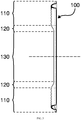
- the suspension element 100 includes two opposing first sections 130 which are connected by two opposing second sections 110 for matching the geometry of the diaphragm 300.
- the second sections 110 are curved and have a curvature radius smaller than that of the first sections 130.
- the first sections 130 are essentially straight, whereby the curvature radius of said straight first sections 130 is approximately infinite.
- all straight bodies have a slight curvature, but nevertheless the curved second section 130 is in any case more curved than the first section 130.
- said first and second sections are in the following referred to as the straight and curved sections 110, 130, respectively.
- the suspension element 100 includes two parallel opposing straight sections 130 and two opposing non-linear sections 110, which connect the two straight sections 130.
- the resulting shape resembles that of a stadium or an "oval" racetrack.
- the non-linear sections 110 are curved and have the shape of a semi-circle.
- the non-linear sections 110 could also have the shape of a plurality of incremental turns or angles, which would add up to an approximated semi-circle.
- the non-linear sections shall hereafter be referred to as curved sections for the sake of simplicity.
- Omitted from Fig. 1 is the chassis and diaphragm, which also have a similar geometry, i.e. "stadium shape".
- driver or diaphragm shape or geometry refers to geometry of the diaphragm when viewed as an orthographic projection of the driver or diaphragm geometry on to a plane in front of the driver or diaphragm, the plane being normal to the direction of motion of the diaphragm and the driver's other moving parts.
- the term axial direction refers to the direction to which the diaphragm of the driver is configured to move.
- the term radial direction means all directions normal to the axial direction in question.
- the term forward means the direction in which the diaphragm moves in an outwards direction, away from the inside (air cavity) of the loudspeaker enclosure.
- the term rearward means the opposite of forward direction, namely the direction in which the diaphragm moves inwards, towards the inside of the loudspeaker enclosure.
- front and rear represent the sides of the driver that are in the direction of forward or rearward directions.
- the straight and curved sections 130, 110 are joined together by a transition section 120.
- the transition sections 120 are preferably straight, but may also be curved.
- the transition sections 120 are in any case shaped to morph from the profile of the straight section 130 to that of the curved section 110.
- stiffness is the derivative of the restoring force exerted by the suspension element with respect to displacement, which is in the field expressed as " ⁇ force/ 8 displacement". If the restoring force exerted by the suspension element is plotted as a function of displacement, then the gradient of the plotted function at any point on the graph gives the stiffness. More precisely, stiffness of a non-linear elastic suspension element is defined as d(f)/dx, where f is the restoring force exerted by the suspension, in Newtons for example, and x is the displacement from the rest position, in meters for example.
- the height of the cross-sectional profile - and therefore the free-length of material used in the suspension element roll - can be increased to reduce the restoring forces exerted by the suspension element in that particular area.
- the height of the cross-sectional profile can be reduced to increase the restoring forces exerted by the suspension element in that particular area.
- stiff straight sections 130 of suspension element 100 By utilizing various combinations of stiff straight sections 130 of suspension element 100 combined with less stiff curved suspension element sections it transpired that an ideal combination can be found from simulations that gives a much more even stiffness profile for small displacements.
- the combination of stiff straight sections 130 and less stiff curved sections 110 also provides a well functioning progressive stiffness profile that successfully prevents damage to the driver 300 caused by over excursion.
- the combination of stiff straight sections 130 and less stiff curved sections 110 creates a well functioning progressive suspension element without the non-linearity's that are commonly found with such progressive suspension elements.
- Figs. 3 to 5 illustrate these design principles by showing cross-sectional views of the suspension element 100 according to one embodiment.
- the height of the cross-sectional profile of the straight section 130 determines the displacement beyond which the progressive nature of the suspension element begins.
- the "free length" of the suspension element roll is relevant because once the suspension element material un-rolls the stiffness rises sharply. More “free-length” means more displacement before the stiffness rises sharply.
- the height of the cross-sectional profile of the straight section 130 is tuned carefully using simulations to give the "flattest" stiffness in the linear area of the stiffness profile. Too little height results in the ends of the stiffness profiles rising up in the linear area. Conversely, too much height results in the ends of the stiffness profiles dropping down in the linear area.
- the length of the straight section 130 determines how much of the restoring forces are focused near middle of the driver.
- the straight section is the stiffest, and has the highest concentration of force. Keeping this highest concentration of force as close to the axis of the driver as possible reduces the distances of diaphragm 300 and suspension element 100 where standing waves can occur. Shorter distances equal higher frequencies, and a higher upper frequency that the driver can be used without coloration from standing wave patterns.
- the curved section 110 of the suspension element 100 is higher than the straight section 130 thereof.
- the mean height of the radial cross-sectional profile of the curved section 110 is higher than the height of the cross-sectional profile of the straight sections 130 when viewed along the circumference of the suspension element 100.
- the increased height of the cross-sectional profile of curved section 110 lowers the stiffness of the curved areas.
- the "free length" of the suspension element roll is relevant because more "free-length" generally results in lower stiffness.
- the curved sections 110 would actually be much stiffer than the straight sections 130. This is far from ideal, as it is preferable to concentrate the restoring forces closer to the middle of the speaker to reduce the distances of the diaphragm and suspension where the standing waves can occur. Shorter distances equal higher frequencies, and a higher upper frequency that the driver can be used without coloration from standing wave patterns.
- the curved sections 110 do not have a flat, linear stiffness profile. Because of this it is preferable to reduce the effect from the very non-linear curved sections stiffness. Since it is desirable that the total stiffness of the suspension element as a whole provides a linear motion to the diaphragm 300, it is preferred to reduce the stiffness from the non-linear curved sections and also increase the stiffness of the very linear straight sections until the stiffness of the whole suspension element 100 looks as close as possible to the ideal stiffness profile.
- the curved section 110 is especially designed to mitigate the effects of a phenomenon known as tangential stress.
- the suspension element material is stretched when the diaphragm moves in one direction and folded in a tangential direction when the diaphragm moves in the opposite direction. This tangential folding is also called buckling or wrinkling. Said tangential forces make the stiffness of the suspension element very non-linear as sudden changes of forces occur as the diaphragm moves and the stiffness of the suspension element is not constant.
- the curved sections 110 of the suspension element 100 where the radius of the suspension element is small compared with the radial width of the suspension element roll, excessive amounts of tangential forces occur, even for small displacements during small excursions.
- the radius of the perimeter is therefore selected to be significantly greater than the radial width of the suspension element's roll of material to avoid tangential stress problems. This is easier to achieve when the shape of the suspension element is essentially round as the radius is maximized. For other shapes, there are areas that have smaller radiuses. The areas with smaller radiuses are more susceptible to problems arising from tangential stress.
- Measures are commonly used to relieve this tangential stress including forming rolls of the suspension element material in the tangential direction. This allows the suspension element material to smoothly expand and contract in the tangential direction as the diaphragm moves without the sudden changes in forces that can occur without any tangential stress relief. Combining the invention with tangential stress relief features allows the buckling problem to be removed, further extending range of displacements where the motion is fairly linear thus allowing larger excursions without high distortion.
- the curved section 110 of the suspension element 130 may be undulated.
- the straight section of the suspension element does not have any such additional features that provide tangential stress relief as only the curved sections suffer from tangential stress problems.
- the mean height of the cross-sectional profile of the curved sections 110 is higher than that of the straight sections 130 of the suspension element 100.
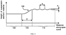
- the curved section 110 has a set mean height and the height undulates up and down. The magnitude of the undulations is expressed with 'A' in Fig. 4 , whereas the spacing of the undulations is denoted with 'B'.
- the fluctuation in height A and the distance between peaks B are design parameters for the curved shape.
- the undulation amplitude A reduces monotonically to zero when moving from the highest point 111 on the cross-section of the suspension element 100 down to the lowest point 112 on the transitional section 120.
- the lowest point of the profile is essentially flat and makes contact to the diaphragm 300.
- stiffness and tangential stress of the curved section 110 may alternatively be controlled by means of ridges, grooves, different widths and material thicknesses etc.
- the two heights above are measured from the lowest suspension element material 112 to the highest suspension element material 111 in the areas indicated in Fig. 5 .
- dimension A is quite small for preventing the peaks from becoming too tall, which would have undesirable resonances.
- a suitable inter-relation between dimensions A and the material thickness is that A is about double the material thickness. Therefore, A is approximately twice the material thickness, whereby B is approximately 11 times the material thickness for providing suitable angles and heights for the undulations.
- the relative heights of the straight and curved sections 130, 110 are is 5 mm and 10 mm, respectively.
- the height of the suspension roll is related to the width of the suspension roll, whereby a one-to-one relationship between width and height forms a geometry that is close to a semi circular roll of material.
- the height of the curved sections may be extended to make the suspension rolls taller than they are wide.
- the slope of the undulations prefferably be very steep, preferably less than 25° to the horizontal, as setting the slopes of the undulations to be too steep increases the amount of material used and therefore adds to the mass of the moving parts.
- too little slope in the undulations will limit the effect of the transitional stress relief, whereby approximately 15 to 20° to the horizontal would be a suitable the average value for the slope of the undulations.
- the transition section 120 between the straight and curved sections 110, 130, respectively provides a gradual transition from the height of the straight section 130 to the mean height of the undulating curved section 110 occurring at the joint of the straight section 130 to the curved section 110.
- the length along the suspension element 100 where this height change occurs is marked with 'C' in Fig. 4 . Accordingly, also the exact shape of this change profile is design parameters for the curved shape.
- the transitional section 120 is essentially straight.
- the slope of the transitional section 120 it is preferable to keep the slope not very steep as setting the slope of the transitional section to be steep increases the amount of material used and therefore adds to the mass of the moving parts. Indeed, it is preferable to lower the mass of the moving parts as this increases efficiency and boosts sensitivity.
- a slope less than 25° to the horizontal is preferred in the transitional section 120.
- dimension C of 10.9 mm would result in a slope of approximately 25° to the horizontal. Dimension C is therefore approximately just over double the change in height between the straight and curved sections 130, 110.
- suspension element 100 Various materials may be used for constructing the suspension element 100. It is, however, preferred that a material with suitable Young's modulus is selected in order to achieve the desired amount of stiffness from the suspension element 100 together with a high loss factor, which is desirable to damp and control any unwanted resonances.
- Fig. 6 shows the structure of a driver equipped with the suspension element 100 as shown with reference to Figs. 1 to 5 .
- the suspension element 100 is attached from its outside perimeter to the chassis 400 of the driver.
- the suspension element 100 is attached from its inner perimeter to the diaphragm 300, which is driven by the voice coil former 200 in cooperation with the magnetic circuit 500.
- the suspension element 100 suspends the diaphragm 300 such that the height of the profile of the suspension element 100 extends rearward from the diaphragm.
- the lowest point of the cross-section suspension element 100 is more forward than the highest point of the cross-section thereof.
- the suspension element 100 may be inverted and used in an opposite orientation, if required, with the peaks pointing forwards. It is a matter of choice based on the space available in the complete loudspeaker design.
- the suspension element is rigidly attached to the chassis.
- the suspension element is carefully attached to the diaphragm with controlled amounts of glue so as not to add too much mass to the moving parts.
- Reinforcement glue may be used to prevent the diaphragm 300 from peeling away from the suspension element 100.
- Other solutions or materials can be added to the junction between the diaphragm and suspension element to damp and control the unwanted resonances. This junction between the diaphragm and suspension element is carefully adjusted to control the standing waves and increase the highest frequency at which the driver can be used with acceptable sound quality, or reduce the audibility of the standing wave resonances if the driver is to be used at or above the standing wave resonance frequencies.
- Figs. 7 and 8 show the stiffness of the suspension element of Fig. 1 as well as the stiffness of an ideal suspension element.
- the restoring forces are focused towards the straight sections as they have the largest stiffness and therefore the dominant forces that are flexing the diaphragm between the voice coil and the straight sections of the suspension element.
- the forces and calculated stiffness profiles relating to the various sections of the suspension element 100 are obtained from finite element analysis software.
- the modeled total stiffness profile of the suspension element of Fig. 1 is the total combination of all of the stiffness profiles relating to the straight sections 130, transition sections 120 and also the curved sections 110. Using finite element analysis software it is possible to separate the contribution from each section of the suspension element 100, thereby analyzing each section individually.
- the "straight section" stiffness profile shows the portion of stiffness related to the straight sections 130 of the suspension element 100 and the "curved section” stiffness profile shows the portion of stiffness related to the curved sections 110 of the suspension element 100.
- FIG 8 shows how the "total" stiffness profile of the suspension element of Fig. 1 compares to an "ideal" stiffness profile for a progressive suspension element.
- the stiffness profile for the "ideal" stiffness profile is flat in the linear range of displacements which is approximately between -0.006 and +0.006 meters. This flat line corresponds to a constant stiffness and therefore no additional distortion is added to the motion of the diaphragm and therefore to the sound output of the driver. It can also be seen how the stiffness of the "ideal" suspension element rises very sharply displacements below -0.008 and displacements above +0.008, this is desirable to protect the driver from damaging itself during very large excursions.
- the stiffness of the curved sections 110 is relatively high when compared to the stiffness profile of the straight sections 130. If the radial cross-sectional geometry of the curved section 110 was the same as the radial cross-sectional geometry of the straight sections 130 then the stiffness profiles of the curved section 110 would completely dominate the stiffness profiles. This is undesirable as the stiffness profile of the curved sections 110 does not resemble the "ideal" stiffness profile (as seen in FIG 8 ) that is desired for a low distortion progressive suspension element. For this reason it is necessary to diminish the contribution from the undesirable curved sections 110 so that the more ideal contribution from the straight sections 130 dominates the overall total stiffness profile for the entire suspension element 100.
- the "straight section” stiffness profile (as seen in FIG 7 ) has some resemblance to the "ideal" stiffness profile of a progressive suspension element in FIG 8 .
- the stiffness In the linear displacement range which is approximately between -0.006 and +0.006 the stiffness varies by approximately 50%.
- the "straight section” stiffness profile rises very sharply for displacements below -0.008 and displacements above +0.008, this is desirable to protect the driver from damaging itself during very large excursions.
- the "curved section” stiffness profile (as seen in FIG 7 ) does not have any resemblance to the "ideal" stiffness profile of a progressive suspension element in FIG 8 .
- the stiffness In the linear displacement range which is approximately between -0.006 and +0.006 the stiffness varies by approximately 65%, this is more non-linear than the straight sections' stiffness profile.
- the "curved section” stiffness profile does not rise at all for displacements below -0.008 and displacements above +0.008, this prevents the progressive behavior from functioning and disables the protection that prevents the driver from damaging itself during very large excursions.
- the "total" stiffness profile has a very close resemblance to the "ideal" stiffness profile of a progressive suspension element in FIG 8 .
- the stiffness varies by approximately 17%, which is much more linear than the individual "straight section” and “curved section” stiffness profiles.
- the “total” stiffness profile rises very sharply for displacements below -0.008 and displacements above +0.008, this is desirable to protect the driver from damaging itself during very large excursions.
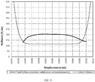
- Fig. 9 shows the stiffness profile of a suspension element that has a constant radial cross-sectional geometry.
- This type of suspension element has the same height cross-sectional geometry on the straight sections and also on the curved sections. There are no undulations that are used to relieve that tangential stress. As can be seen from Fig. 9 the progressive nature of the suspension element has been lost. In the linear displacement range which is approximately between -0.006 and +0.006 the stiffness varies by approximately 10%, which is very linear indeed.
- the magnitude of the stiffness of the constant radial cross-sectional geometry is much higher than the ideal stiffness. It is preferred to have a low stiffness, i.e. a more compliant design, for the suspension element.
- the low stiffness design is preferred to achieve a low driver free air resonance with a low moving mass.
Landscapes
- Engineering & Computer Science (AREA)
- Multimedia (AREA)
- Physics & Mathematics (AREA)
- Acoustics & Sound (AREA)
- Signal Processing (AREA)
- Audible-Bandwidth Dynamoelectric Transducers Other Than Pickups (AREA)
- Diaphragms For Electromechanical Transducers (AREA)
Applications Claiming Priority (1)
| Application Number | Priority Date | Filing Date | Title |
|---|---|---|---|
| PCT/FI2013/050653 WO2014199000A1 (en) | 2013-06-14 | 2013-06-14 | Suspension element for suspending the diaphragm of a loudspeaker driver to the chassis thereof as well as driver and loudspeaker comprising the same |
Publications (2)
| Publication Number | Publication Date |
|---|---|
| EP3008917A1 EP3008917A1 (en) | 2016-04-20 |
| EP3008917B1 true EP3008917B1 (en) | 2021-12-22 |
Family
ID=48795583
Family Applications (1)
| Application Number | Title | Priority Date | Filing Date |
|---|---|---|---|
| EP13737842.8A Active EP3008917B1 (en) | 2013-06-14 | 2013-06-14 | Suspension element for suspending the diaphragm of a loudspeaker driver to the chassis thereof as well as driver and loudspeaker comprising the same |
Country Status (8)
| Country | Link |
|---|---|
| US (1) | US9838793B2 (es) |
| EP (1) | EP3008917B1 (es) |
| JP (1) | JP6716454B2 (es) |
| CN (1) | CN105453590B (es) |
| CA (1) | CA2911434C (es) |
| DK (1) | DK3008917T3 (es) |
| ES (1) | ES2908079T3 (es) |
| WO (1) | WO2014199000A1 (es) |
Families Citing this family (3)
| Publication number | Priority date | Publication date | Assignee | Title |
|---|---|---|---|---|
| DK3008917T3 (da) * | 2013-06-14 | 2022-03-07 | Genelec Oy | Ophængningselement til ophængning af membranen af en højtalerenhed på rammen deraf såvel som enhed og højtaler omfattende samme |
| CN109788408B (zh) * | 2017-11-10 | 2023-08-22 | 惠州迪芬尼声学科技股份有限公司 | 扬声器的悬边结构 |
| CN108900955B (zh) * | 2018-06-27 | 2021-02-05 | 歌尔股份有限公司 | 振膜和扬声器 |
Citations (3)
| Publication number | Priority date | Publication date | Assignee | Title |
|---|---|---|---|---|
| JPH08102992A (ja) * | 1994-10-03 | 1996-04-16 | Matsushita Electric Ind Co Ltd | スピーカ |
| EP1517582A1 (en) * | 2002-06-26 | 2005-03-23 | Matsushita Electric Industrial Co., Ltd. | Loudspeaker edge |
| JP2006203490A (ja) * | 2005-01-20 | 2006-08-03 | Matsushita Electric Ind Co Ltd | スピーカ |
Family Cites Families (45)
| Publication number | Priority date | Publication date | Assignee | Title |
|---|---|---|---|---|
| US2302178A (en) * | 1940-11-12 | 1942-11-17 | Joseph B Brennan | Acoustic diaphragm |
| US4327257A (en) * | 1979-09-10 | 1982-04-27 | Schwartz Leslie H | Alignment device for electro-acoustical transducers |
| US4433214A (en) * | 1981-12-24 | 1984-02-21 | Motorola, Inc. | Acoustical transducer with a slotted piston suspension |
| US5216723A (en) * | 1991-03-11 | 1993-06-01 | Bose Corporation | Permanent magnet transducing |
| JP3049936B2 (ja) * | 1992-05-07 | 2000-06-05 | 松下電器産業株式会社 | 楕円形スピーカ |
| US5450499A (en) * | 1992-11-25 | 1995-09-12 | Magnetic Resonance Equipment Corporation | Audio speaker for use in an external magnetic field |
| JP3132253B2 (ja) | 1993-07-30 | 2001-02-05 | 松下電器産業株式会社 | スピーカ用エッジ |
| DK110993D0 (da) * | 1993-10-04 | 1993-10-04 | Vifa Speak As | Hoejttaler |
| JPH0879885A (ja) | 1994-09-09 | 1996-03-22 | Matsushita Electric Ind Co Ltd | スピーカ |
| KR100445212B1 (ko) * | 1996-05-31 | 2004-12-03 | 코닌클리케 필립스 일렉트로닉스 엔.브이. | 전기역학적확성기및확성기시스템 |
| JPH10257590A (ja) | 1997-03-17 | 1998-09-25 | Hitachi Ltd | スピーカユニットとそれを用いたavc機器 |
| JPH11146488A (ja) | 1997-11-07 | 1999-05-28 | Hitachi Ltd | コーン形スピーカユニット、スピーカシステム及びディスプレイ装置、ステレオ装置、車載ステレオ装置 |
| US6611604B1 (en) * | 1999-10-22 | 2003-08-26 | Stillwater Designs & Audio, Inc. | Ultra low frequency transducer and loud speaker comprising same |
| US6445803B1 (en) * | 1999-12-16 | 2002-09-03 | Chuan How Boon | Speaker |
| US6862361B2 (en) * | 2001-04-05 | 2005-03-01 | Floyd John James | Audio speaker |
| EP1377115B1 (en) * | 2002-06-24 | 2016-01-06 | Panasonic Intellectual Property Management Co., Ltd. | Loudspeaker diaphragm |
| JP3651470B2 (ja) * | 2003-03-31 | 2005-05-25 | 松下電器産業株式会社 | スピーカ |
| US6865282B2 (en) * | 2003-05-01 | 2005-03-08 | Richard L. Weisman | Loudspeaker suspension for achieving very long excursion |
| US20050147272A1 (en) * | 2004-01-07 | 2005-07-07 | Adire Audio | Speaker suspension element |
| US8139812B2 (en) * | 2004-11-19 | 2012-03-20 | Subarna Basnet | Loudspeaker suspension |
| JP2006339831A (ja) | 2005-05-31 | 2006-12-14 | Pioneer Electronic Corp | スピーカ |
| EP1935210A4 (en) * | 2005-10-13 | 2009-12-23 | Velodyne Acoustics Inc | WALL INTERNAL SPEAKER |
| JP4867442B2 (ja) | 2006-04-10 | 2012-02-01 | パナソニック株式会社 | スピーカ振動板とそれを用いたスピーカ |
| US7275620B1 (en) * | 2007-07-19 | 2007-10-02 | Mitek Corp., Inc. | Square speaker |
| EP2258117B1 (en) * | 2008-03-05 | 2019-10-09 | Genelec OY | Nested compound loudspeaker drive unit |
| US8085971B2 (en) * | 2008-05-23 | 2011-12-27 | Tai Yan Kam | Moving-coil planar speaker |
| EP2180721A1 (de) * | 2008-10-21 | 2010-04-28 | Lautsprecher Teufel GmbH | Flachmembranlautsprecher |
| JP2010226373A (ja) | 2009-03-23 | 2010-10-07 | Fujitsu Ten Ltd | スピーカ |
| JP2009183002A (ja) | 2009-05-20 | 2009-08-13 | Victor Co Of Japan Ltd | 電気音響変換器 |
| US8340340B2 (en) * | 2010-01-07 | 2012-12-25 | Paradigm Electronics Inc. | Loudspeaker driver suspension |
| US8295537B2 (en) * | 2010-03-31 | 2012-10-23 | Bose Corporation | Loudspeaker moment and torque balancing |
| US20110243364A1 (en) * | 2010-03-31 | 2011-10-06 | Walter James J | Structure of loudspeaker for reducing thickness and mounting depth |
| US8295536B2 (en) * | 2010-03-31 | 2012-10-23 | Bose Corporation | Moving magnet levered loudspeaker |
| CN201967124U (zh) * | 2011-01-07 | 2011-09-07 | 瑞声光电科技(常州)有限公司 | 电磁扬声器 |
| US8774420B2 (en) * | 2011-06-29 | 2014-07-08 | Get Connected Llc | Headphones with expandable speaker enclosures |
| US8397861B1 (en) * | 2012-03-02 | 2013-03-19 | Bose Corporation | Diaphragm surround |
| US9538292B1 (en) * | 2012-03-23 | 2017-01-03 | Coleridge Design Associates Llc | Speaker with voice coil and field coil |
| US9900703B2 (en) * | 2012-08-23 | 2018-02-20 | Em-Tech. Co., Ltd. | Suspension for high power micro speaker and high power micro speaker having the same |
| HU230260B1 (hu) * | 2012-09-17 | 2015-11-30 | NOVINEX Innováció- és Kutatás-hasznosító Iroda Kft. | Koaxiális hangszóró elrendezés |
| WO2014082295A1 (en) * | 2012-11-30 | 2014-06-05 | Premium Loudspeakers (Hui Zhou) Co., Ltd. | A loudspeaker with two motors and one suspension |
| US10028062B2 (en) * | 2013-03-15 | 2018-07-17 | Bose Corporation | Driving plural armatures with a common stator |
| DK3008917T3 (da) * | 2013-06-14 | 2022-03-07 | Genelec Oy | Ophængningselement til ophængning af membranen af en højtalerenhed på rammen deraf såvel som enhed og højtaler omfattende samme |
| US9232314B2 (en) * | 2013-09-09 | 2016-01-05 | Sonos, Inc. | Loudspeaker configuration |
| US9363593B2 (en) * | 2014-05-01 | 2016-06-07 | Bose Corporation | Transducer suspension elements with built-in tinsel wire |
| US9693146B2 (en) * | 2015-09-11 | 2017-06-27 | Sonos, Inc. | Transducer diaphragm |
-
2013
- 2013-06-14 DK DK13737842.8T patent/DK3008917T3/da active
- 2013-06-14 ES ES13737842T patent/ES2908079T3/es active Active
- 2013-06-14 JP JP2016518548A patent/JP6716454B2/ja active Active
- 2013-06-14 CN CN201380077394.4A patent/CN105453590B/zh active Active
- 2013-06-14 CA CA2911434A patent/CA2911434C/en active Active
- 2013-06-14 WO PCT/FI2013/050653 patent/WO2014199000A1/en active Application Filing
- 2013-06-14 US US14/898,104 patent/US9838793B2/en active Active
- 2013-06-14 EP EP13737842.8A patent/EP3008917B1/en active Active
Patent Citations (3)
| Publication number | Priority date | Publication date | Assignee | Title |
|---|---|---|---|---|
| JPH08102992A (ja) * | 1994-10-03 | 1996-04-16 | Matsushita Electric Ind Co Ltd | スピーカ |
| EP1517582A1 (en) * | 2002-06-26 | 2005-03-23 | Matsushita Electric Industrial Co., Ltd. | Loudspeaker edge |
| JP2006203490A (ja) * | 2005-01-20 | 2006-08-03 | Matsushita Electric Ind Co Ltd | スピーカ |
Also Published As
| Publication number | Publication date |
|---|---|
| WO2014199000A1 (en) | 2014-12-18 |
| JP2016524411A (ja) | 2016-08-12 |
| EP3008917A1 (en) | 2016-04-20 |
| CA2911434A1 (en) | 2014-12-18 |
| CA2911434C (en) | 2020-06-30 |
| ES2908079T3 (es) | 2022-04-27 |
| CN105453590B (zh) | 2019-01-25 |
| CN105453590A (zh) | 2016-03-30 |
| US20160142825A1 (en) | 2016-05-19 |
| JP6716454B2 (ja) | 2020-07-01 |
| US9838793B2 (en) | 2017-12-05 |
| DK3008917T3 (da) | 2022-03-07 |
Similar Documents
| Publication | Publication Date | Title |
|---|---|---|
| EP2227036B1 (en) | Improved membrane for an electroacoustic transducer | |
| CA2407123C (en) | Low distortion loudspeaker cone suspension | |
| US8411894B2 (en) | Transducer with deformable corner | |
| US20200321511A1 (en) | Transducers With Improved Impedance Matching | |
| EP3008917B1 (en) | Suspension element for suspending the diaphragm of a loudspeaker driver to the chassis thereof as well as driver and loudspeaker comprising the same | |
| CN110140361B (zh) | 声学受话器振膜与声学受话器 | |
| US9226074B2 (en) | Surround with variations of concavity | |
| CN102884812B (zh) | 扬声器 | |
| WO2012088196A1 (en) | Acoustic diaphragm suspending | |
| EP2454890B1 (en) | Ring-shaped surround for loudspeakers | |
| KR101560365B1 (ko) | 스피커 장치의 진동판 | |
| US8428298B2 (en) | Damper for speaker and speaker using the damper | |
| CN114946198A (zh) | 扬声器定心支片的改进以及与其相关的改进 | |
| US20190335270A1 (en) | Speaker | |
| US20200314563A1 (en) | Receiver suspension for a hearing assisting device | |
| JP2018157592A (ja) | ラウドスピーカドライバの振動板をラウドスピーカドライバのシャーシに取りつけるサスペンション部材、並びに、ドライバ、及びドライバを有するラウドスピーカ | |
| CN111083604A (zh) | 电动声学换能器 | |
| US20170318391A1 (en) | Diaphragm for speaker apparatus | |
| JP2013128163A (ja) | スピーカ | |
| US20190200138A1 (en) | Acoustic transducer with pivoted surround |
Legal Events
| Date | Code | Title | Description |
|---|---|---|---|
| PUAI | Public reference made under article 153(3) epc to a published international application that has entered the european phase |
Free format text: ORIGINAL CODE: 0009012 |
|
| 17P | Request for examination filed |
Effective date: 20151126 |
|
| AK | Designated contracting states |
Kind code of ref document: A1 Designated state(s): AL AT BE BG CH CY CZ DE DK EE ES FI FR GB GR HR HU IE IS IT LI LT LU LV MC MK MT NL NO PL PT RO RS SE SI SK SM TR |
|
| AX | Request for extension of the european patent |
Extension state: BA ME |
|
| DAX | Request for extension of the european patent (deleted) | ||
| STAA | Information on the status of an ep patent application or granted ep patent |
Free format text: STATUS: EXAMINATION IS IN PROGRESS |
|
| 17Q | First examination report despatched |
Effective date: 20181128 |
|
| STAA | Information on the status of an ep patent application or granted ep patent |
Free format text: STATUS: EXAMINATION IS IN PROGRESS |
|
| GRAP | Despatch of communication of intention to grant a patent |
Free format text: ORIGINAL CODE: EPIDOSNIGR1 |
|
| STAA | Information on the status of an ep patent application or granted ep patent |
Free format text: STATUS: GRANT OF PATENT IS INTENDED |
|
| INTG | Intention to grant announced |
Effective date: 20210715 |
|
| GRAS | Grant fee paid |
Free format text: ORIGINAL CODE: EPIDOSNIGR3 |
|
| GRAA | (expected) grant |
Free format text: ORIGINAL CODE: 0009210 |
|
| STAA | Information on the status of an ep patent application or granted ep patent |
Free format text: STATUS: THE PATENT HAS BEEN GRANTED |
|
| AK | Designated contracting states |
Kind code of ref document: B1 Designated state(s): AL AT BE BG CH CY CZ DE DK EE ES FI FR GB GR HR HU IE IS IT LI LT LU LV MC MK MT NL NO PL PT RO RS SE SI SK SM TR |
|
| REG | Reference to a national code |
Ref country code: GB Ref legal event code: FG4D |
|
| REG | Reference to a national code |
Ref country code: CH Ref legal event code: EP |
|
| REG | Reference to a national code |
Ref country code: DE Ref legal event code: R096 Ref document number: 602013080484 Country of ref document: DE |
|
| REG | Reference to a national code |
Ref country code: AT Ref legal event code: REF Ref document number: 1457887 Country of ref document: AT Kind code of ref document: T Effective date: 20220115 |
|
| REG | Reference to a national code |
Ref country code: IE Ref legal event code: FG4D |
|
| REG | Reference to a national code |
Ref country code: DK Ref legal event code: T3 Effective date: 20220301 |
|
| REG | Reference to a national code |
Ref country code: FI Ref legal event code: FGE |
|
| REG | Reference to a national code |
Ref country code: LT Ref legal event code: MG9D |
|
| REG | Reference to a national code |
Ref country code: ES Ref legal event code: FG2A Ref document number: 2908079 Country of ref document: ES Kind code of ref document: T3 Effective date: 20220427 |
|
| PG25 | Lapsed in a contracting state [announced via postgrant information from national office to epo] |
Ref country code: RS Free format text: LAPSE BECAUSE OF FAILURE TO SUBMIT A TRANSLATION OF THE DESCRIPTION OR TO PAY THE FEE WITHIN THE PRESCRIBED TIME-LIMIT Effective date: 20211222 Ref country code: LT Free format text: LAPSE BECAUSE OF FAILURE TO SUBMIT A TRANSLATION OF THE DESCRIPTION OR TO PAY THE FEE WITHIN THE PRESCRIBED TIME-LIMIT Effective date: 20211222 Ref country code: BG Free format text: LAPSE BECAUSE OF FAILURE TO SUBMIT A TRANSLATION OF THE DESCRIPTION OR TO PAY THE FEE WITHIN THE PRESCRIBED TIME-LIMIT Effective date: 20220322 |
|
| REG | Reference to a national code |
Ref country code: NL Ref legal event code: MP Effective date: 20211222 |
|
| REG | Reference to a national code |
Ref country code: AT Ref legal event code: MK05 Ref document number: 1457887 Country of ref document: AT Kind code of ref document: T Effective date: 20211222 |
|
| PG25 | Lapsed in a contracting state [announced via postgrant information from national office to epo] |
Ref country code: SE Free format text: LAPSE BECAUSE OF FAILURE TO SUBMIT A TRANSLATION OF THE DESCRIPTION OR TO PAY THE FEE WITHIN THE PRESCRIBED TIME-LIMIT Effective date: 20211222 Ref country code: NO Free format text: LAPSE BECAUSE OF FAILURE TO SUBMIT A TRANSLATION OF THE DESCRIPTION OR TO PAY THE FEE WITHIN THE PRESCRIBED TIME-LIMIT Effective date: 20220322 Ref country code: LV Free format text: LAPSE BECAUSE OF FAILURE TO SUBMIT A TRANSLATION OF THE DESCRIPTION OR TO PAY THE FEE WITHIN THE PRESCRIBED TIME-LIMIT Effective date: 20211222 Ref country code: HR Free format text: LAPSE BECAUSE OF FAILURE TO SUBMIT A TRANSLATION OF THE DESCRIPTION OR TO PAY THE FEE WITHIN THE PRESCRIBED TIME-LIMIT Effective date: 20211222 Ref country code: GR Free format text: LAPSE BECAUSE OF FAILURE TO SUBMIT A TRANSLATION OF THE DESCRIPTION OR TO PAY THE FEE WITHIN THE PRESCRIBED TIME-LIMIT Effective date: 20220323 |
|
| PG25 | Lapsed in a contracting state [announced via postgrant information from national office to epo] |
Ref country code: NL Free format text: LAPSE BECAUSE OF FAILURE TO SUBMIT A TRANSLATION OF THE DESCRIPTION OR TO PAY THE FEE WITHIN THE PRESCRIBED TIME-LIMIT Effective date: 20211222 |
|
| PG25 | Lapsed in a contracting state [announced via postgrant information from national office to epo] |
Ref country code: SM Free format text: LAPSE BECAUSE OF FAILURE TO SUBMIT A TRANSLATION OF THE DESCRIPTION OR TO PAY THE FEE WITHIN THE PRESCRIBED TIME-LIMIT Effective date: 20211222 Ref country code: SK Free format text: LAPSE BECAUSE OF FAILURE TO SUBMIT A TRANSLATION OF THE DESCRIPTION OR TO PAY THE FEE WITHIN THE PRESCRIBED TIME-LIMIT Effective date: 20211222 Ref country code: RO Free format text: LAPSE BECAUSE OF FAILURE TO SUBMIT A TRANSLATION OF THE DESCRIPTION OR TO PAY THE FEE WITHIN THE PRESCRIBED TIME-LIMIT Effective date: 20211222 Ref country code: PT Free format text: LAPSE BECAUSE OF FAILURE TO SUBMIT A TRANSLATION OF THE DESCRIPTION OR TO PAY THE FEE WITHIN THE PRESCRIBED TIME-LIMIT Effective date: 20220422 Ref country code: EE Free format text: LAPSE BECAUSE OF FAILURE TO SUBMIT A TRANSLATION OF THE DESCRIPTION OR TO PAY THE FEE WITHIN THE PRESCRIBED TIME-LIMIT Effective date: 20211222 Ref country code: CZ Free format text: LAPSE BECAUSE OF FAILURE TO SUBMIT A TRANSLATION OF THE DESCRIPTION OR TO PAY THE FEE WITHIN THE PRESCRIBED TIME-LIMIT Effective date: 20211222 |
|
| PG25 | Lapsed in a contracting state [announced via postgrant information from national office to epo] |
Ref country code: PL Free format text: LAPSE BECAUSE OF FAILURE TO SUBMIT A TRANSLATION OF THE DESCRIPTION OR TO PAY THE FEE WITHIN THE PRESCRIBED TIME-LIMIT Effective date: 20211222 Ref country code: AT Free format text: LAPSE BECAUSE OF FAILURE TO SUBMIT A TRANSLATION OF THE DESCRIPTION OR TO PAY THE FEE WITHIN THE PRESCRIBED TIME-LIMIT Effective date: 20211222 |
|
| REG | Reference to a national code |
Ref country code: DE Ref legal event code: R097 Ref document number: 602013080484 Country of ref document: DE |
|
| PG25 | Lapsed in a contracting state [announced via postgrant information from national office to epo] |
Ref country code: IS Free format text: LAPSE BECAUSE OF FAILURE TO SUBMIT A TRANSLATION OF THE DESCRIPTION OR TO PAY THE FEE WITHIN THE PRESCRIBED TIME-LIMIT Effective date: 20220422 |
|
| PLBE | No opposition filed within time limit |
Free format text: ORIGINAL CODE: 0009261 |
|
| STAA | Information on the status of an ep patent application or granted ep patent |
Free format text: STATUS: NO OPPOSITION FILED WITHIN TIME LIMIT |
|
| PG25 | Lapsed in a contracting state [announced via postgrant information from national office to epo] |
Ref country code: AL Free format text: LAPSE BECAUSE OF FAILURE TO SUBMIT A TRANSLATION OF THE DESCRIPTION OR TO PAY THE FEE WITHIN THE PRESCRIBED TIME-LIMIT Effective date: 20211222 |
|
| 26N | No opposition filed |
Effective date: 20220923 |
|
| PG25 | Lapsed in a contracting state [announced via postgrant information from national office to epo] |
Ref country code: MC Free format text: LAPSE BECAUSE OF FAILURE TO SUBMIT A TRANSLATION OF THE DESCRIPTION OR TO PAY THE FEE WITHIN THE PRESCRIBED TIME-LIMIT Effective date: 20211222 |
|
| REG | Reference to a national code |
Ref country code: CH Ref legal event code: PL |
|
| REG | Reference to a national code |
Ref country code: BE Ref legal event code: MM Effective date: 20220630 |
|
| PG25 | Lapsed in a contracting state [announced via postgrant information from national office to epo] |
Ref country code: SI Free format text: LAPSE BECAUSE OF FAILURE TO SUBMIT A TRANSLATION OF THE DESCRIPTION OR TO PAY THE FEE WITHIN THE PRESCRIBED TIME-LIMIT Effective date: 20211222 |
|
| PG25 | Lapsed in a contracting state [announced via postgrant information from national office to epo] |
Ref country code: LU Free format text: LAPSE BECAUSE OF NON-PAYMENT OF DUE FEES Effective date: 20220614 Ref country code: LI Free format text: LAPSE BECAUSE OF NON-PAYMENT OF DUE FEES Effective date: 20220630 Ref country code: IE Free format text: LAPSE BECAUSE OF NON-PAYMENT OF DUE FEES Effective date: 20220614 Ref country code: CH Free format text: LAPSE BECAUSE OF NON-PAYMENT OF DUE FEES Effective date: 20220630 |
|
| PG25 | Lapsed in a contracting state [announced via postgrant information from national office to epo] |
Ref country code: BE Free format text: LAPSE BECAUSE OF NON-PAYMENT OF DUE FEES Effective date: 20220630 |
|
| PGFP | Annual fee paid to national office [announced via postgrant information from national office to epo] |
Ref country code: FR Payment date: 20230628 Year of fee payment: 11 Ref country code: DK Payment date: 20230622 Year of fee payment: 11 Ref country code: DE Payment date: 20230620 Year of fee payment: 11 |
|
| PGFP | Annual fee paid to national office [announced via postgrant information from national office to epo] |
Ref country code: FI Payment date: 20230605 Year of fee payment: 11 |
|
| PGFP | Annual fee paid to national office [announced via postgrant information from national office to epo] |
Ref country code: IT Payment date: 20230623 Year of fee payment: 11 Ref country code: GB Payment date: 20230622 Year of fee payment: 11 Ref country code: ES Payment date: 20230829 Year of fee payment: 11 |
|
| PG25 | Lapsed in a contracting state [announced via postgrant information from national office to epo] |
Ref country code: HU Free format text: LAPSE BECAUSE OF FAILURE TO SUBMIT A TRANSLATION OF THE DESCRIPTION OR TO PAY THE FEE WITHIN THE PRESCRIBED TIME-LIMIT; INVALID AB INITIO Effective date: 20130614 |