EP3007976B1 - Verfahren zum sichern und entsichern einer aufblasbaren notrutsche und mechanismus zur durchführung des verfahrens - Google Patents
Verfahren zum sichern und entsichern einer aufblasbaren notrutsche und mechanismus zur durchführung des verfahrens Download PDFInfo
- Publication number
- EP3007976B1 EP3007976B1 EP14736655.3A EP14736655A EP3007976B1 EP 3007976 B1 EP3007976 B1 EP 3007976B1 EP 14736655 A EP14736655 A EP 14736655A EP 3007976 B1 EP3007976 B1 EP 3007976B1
- Authority
- EP
- European Patent Office
- Prior art keywords
- door
- connector
- assembly according
- arming
- floor
- Prior art date
- Legal status (The legal status is an assumption and is not a legal conclusion. Google has not performed a legal analysis and makes no representation as to the accuracy of the status listed.)
- Active
Links
Images


Classifications
-
- B—PERFORMING OPERATIONS; TRANSPORTING
- B64—AIRCRAFT; AVIATION; COSMONAUTICS
- B64D—EQUIPMENT FOR FITTING IN OR TO AIRCRAFT; FLIGHT SUITS; PARACHUTES; ARRANGEMENT OR MOUNTING OF POWER PLANTS OR PROPULSION TRANSMISSIONS IN AIRCRAFT
- B64D25/00—Emergency apparatus or devices, not otherwise provided for
- B64D25/08—Ejecting or escaping means
- B64D25/14—Inflatable escape chutes
-
- B—PERFORMING OPERATIONS; TRANSPORTING
- B64—AIRCRAFT; AVIATION; COSMONAUTICS
- B64C—AEROPLANES; HELICOPTERS
- B64C1/00—Fuselages; Constructional features common to fuselages, wings, stabilising surfaces or the like
- B64C1/14—Windows; Doors; Hatch covers or access panels; Surrounding frame structures; Canopies; Windscreens accessories therefor, e.g. pressure sensors, water deflectors, hinges, seals, handles, latches, windscreen wipers
- B64C1/1407—Doors; surrounding frames
Definitions
- the invention relates to a method for arming/disarming an aircraft door slide in connection with the cabin floor of the aircraft, as well as to a mechanism for implementing such a method.
- the doors are equipped with an inflatable passenger emergency exit slide, for example during an unplanned landing.
- the cabin floor of these aircraft is indeed too high to allow passengers and crew to jump from the aircraft without exposing themselves to serious injury.
- a command allows the slide to be armed or disarmed and a visual indicator allows the operator to know the arming status of each slide at any time.
- the operator activates the control before take-off to check that the status change of the door is working correctly, which changes from the "disarm” or DISARM status - where the slide cannot be released - to the "arm” or ARM status which allows the slide to be released if necessary .
- the ARM/DISARM control corresponds to two positions of a dedicated handle which also visually indicates the status of the door.
- a light indicator can confirm this status at any time.
- the slide In the disarmed position, the slide is attached in the form of a tube enveloping the attachment bar and is stored in a box fixed to the internal wall of the door, the box being arranged at the bottom of the door or in the fuselage, under the sill of the door. door, in some installations.
- the attachment bar is held parallel to the floor of the cabin by "U” clamps equipped with releasable clips formed of a spring blade or equivalent.
- the detachment of the bar is obtained by a mechanism for releasing the jaws actuated for example by a cable connected to an auxiliary handle.
- a visual indicator reinforced by an audible indicator, warns the operator that the slide of the door he is trying to open is armed.
- the invention aims to overcome these drawbacks by decoupling the control and information aspect from the activation aspect, and by eliminating the attachment bar replaced by a slide link at attachment points. These attachment points then move by electrical control to grip reversibly to fixed fittings without anchoring. The mechanism for driving the attachment points is then completely on the side of the door, well protected from environmental attacks.
- the invention also relates to a method for arming/disarming a slide according to claim 14 with particular embodiments of the method identified in the dependent claims 15-17.
- upper and lower refer to locations of elements or parts of elements positioned relative to surface level. landing or ditching in the broad sense (ground or water) considered as a horizontal reference plane.
- This Door 1 is the usual front passenger entry/exit door. It is equipped in particular with a lifting / lowering handle 11, an arm 12 for opening the door 1 in order to allow the access or the exit of the passengers and an arming / disarming mechanism 2 according to the 'invention.
- This arming/disarming mechanism 2 makes it possible to use a slide 3 stored in the trunk 4 formed at the bottom of the door 1 in cases of emergency which require the evacuation of the occupants of the aircraft.
- the operation of this mechanism 2 is triggered by pressing the DISARM 51 or ARM 52 control buttons.
- Light diodes 5a and 5b are placed opposite the buttons 51 and 52 to signal the respectively armed or disarmed state of the mechanism.
- backlit buttons or equivalent can replace the diodes.
- the underside 4i of the box 4 is located substantially at the same level as the underside 1i of the door structure.
- the mechanism 2 comprises two releasable connectors 21 and 22 arranged on each side of the bottom of the door.
- Each connector 21, 22 is made up of two half-connectors, a so-called upper half-connector 21s, 22s fixed to a reinforcing structure 16 of door 1, and a so-called lower half-connector 21i, 22i.
- Each lower half-connector 21i, 22i is formed by a fitting, called a fitting, threshold fixed to the cabin floor 6.
- the door 1 is lowered into the closed position and the half-connectors 21s and 22s are engaged on the threshold fittings 21i and 22i.
- the description applies to the other connector 22 or a half-connector 22i, 22s.
- the mechanism 2 also comprises a bistable electric motor 23, of the solenoid type, controlled by a door computer 14 and actuated by the control buttons 51 and 52.
- the motor 23 is coupled to two connecting rods 31 and 32, each connecting rod rotating respectively an upper half-connector 21, 22s between a locking position called arming or ARM and a releasable position called disarming or DISARM which will be detailed below.
- the figure 2 illustrates a side view of the door 1 and the releasable connector 21, the picture 3 showing a sectional view of the connector 21.
- the door 1 consists of a panel 15 and a reinforcement structure 16 in which are housed in particular the control, actuation and management equipment for door 1.
- the upper half-connector 21s has attachment pins 33 for the slide 3 stored in the trunk 4 and a fixing arm 41 to the trunk 4.
- This half-connector 21s of the female type is coupled to a threshold fitting 21i of the male type , fixed to the cabin floor 6 to form the releasable connector 21 as explained below.
- the upper half-connector 21s comprises a candle 42 mounted vertically and perpendicular to the floor 6 by the fixing arm 41, a control ring 43 movable in rotation mounted on the candle 42 and connected to the drive rod 31, and a grab locking / unlocking 7 also mounted on the candle 42.
- the seal 45 made of elastic material - for example silicone - for mounting the candle 42 in the annular support 41a of the fixing arm 41.
- This elastic seal 45 is intended to absorb the misalignments between the half-connectors, for example during their connection during the descent of the door in the closed position or during relative movements in flight between the door and the fuselage.
- position sensors 47 and 48 are advantageously mounted on the candle 42 of the upper half-connector 21s via a support 40c. These sensors 47 and 48 associated with a target 72c present on the grab 7 (see figure 5c ) make it possible to follow the movement of the grapple, to ensure its correct operation, to determine the angular position of the ring 43 (cf. figures 7a and 7b ), and to deduce the arming/disarming status of the slide.
- FIG. 4b shows the coupling of the drive rod 31 on the movable ring 43 by an annular end piece 31a formed at the end of the rod 31 in connection with a lug 43a coming from a base 40 fixed on the face upper 43s of the ring 43.
- the figure 4b also illustrates the presence of three lugs 43e formed on an underside 43i of the control ring 43, these lugs being intended to be coupled to the internal moving part 72 of a grab 7.
- the grapple 7 consists of an outer casing 71 and the internal moving part 72.
- the outer casing 71 has hooking pins 33 for the slide as well as, advantageously, an inner wall 73 having a central cylindrical bore 73a for centering threshold fitting 21i (cf. figures 6a to 6c ).
- this known indexing system is mounted here in a housing 49 formed in the housing 71 at the birth of a pin 33 in the example illustrated.
- the indexing system works in conjunction with a recessed marker 46 formed in a vertical annular wall 72v of part 72.
- the vertical annular wall 72v is integrated into a corresponding gap in the housing 71.
- This annular wall 72v has on its upper face 72s three reinforced notches 72e, each of these notches being able to accommodate a lug 43e formed on the lower face 43i of the control ring 43 (cf. figure 4b ). Each lug can then move along a circular slot 72l made on the upper face 71s of the housing 71.
- the annular wall 72v of the moving part 72 is extended on its lower part by a horizontal wall 72h.
- This horizontal wall 72h has a central bore 72a of conformation adapted to the conformation of the threshold fitting in order to define locking and releasable positions as will be detailed below.
- the moving part 72 is provided with a target 72c for the position sensors 47, 48 of the grapple (cf. figures 4a and 4b ).
- the 72c target forms a pull cord that can be operated manually to arm or disarm the door in the event of an electric motor failure.
- the side views and the top view of the figures 6a to 6c illustrate a threshold fitting 21i of connector 21 (cf. figures 2 and 3 ) able to connect to the upper half-connector 21s described above.
- This threshold fitting 21i comprises a base 8 intended to be fixed to the cabin floor 6 (cf. figure 1 ), the base 8 resting on this floor 6 so that no cavity forms between the base 8 and the threshold.
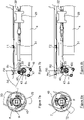
- FIG. 7a and 7b illustrate the connector 21 (partially cut away) and the arming/disarming mechanism 2 towards the DISARM disarming position.
- motor 23 is actuated by control 51 and door computer 14 ( figure 1 ) so that the translational movement T1 of the drive rods 31 and 32 causes the control ring 43 to pivot in rotation R1 according to a decocking angle Ad (relative to a reference R 0 ) for which the grabs 7 are not in a blocking position on the threshold fitting 21i.
- the grabs 7 and therefore the connections 21, 22 are released: the door can be lifted to uncouple the connections then opened with the arm 12 ( figure 1 ) under nominal conditions.
- FIGS. 8a and 8b which take up the superior views of the figures 7a and 7b in the ARM position.
- the door 1 is in the closed position and the grabs 7 are locked in an angular position blocking on the threshold fittings 21i by rotation of the control ring 43 according to an arming angle i.
- the connecting rods 31, 32 are actuated according to a blocking kinematics triggered by the control 52 and the door computer 14 ( figure 1 ) via the electric motor 23.
- the rotational drive causes a mobile sub-assembly of one of the parts of each connection to pivot between two extreme positions, a locking position in which the sub-assembly is arranged in a housing of the other part according to a blocking conformation and a releasable position in which the subassembly and the housing have complementary conformations.
Landscapes
- Engineering & Computer Science (AREA)
- Aviation & Aerospace Engineering (AREA)
- Business, Economics & Management (AREA)
- Emergency Management (AREA)
- Mechanical Engineering (AREA)
- Lock And Its Accessories (AREA)
- Emergency Lowering Means (AREA)
- Power-Operated Mechanisms For Wings (AREA)
- Electric Cable Arrangement Between Relatively Moving Parts (AREA)
Claims (17)
- Anordnung aus einer Flugzeugtür (1), einer Flugzeugtür-Notrutsche (3), einem Flugzeugkabinenboden (6) und einem Mechanismus zum Scharfschalten / Entschärfen der Notrutsche (3) in Verbindung mit dem Kabinenboden des Flugzeugs (6), dadurch gekennzeichnet, dass sie zwei lösbare Verbinder (21, 22) umfasst, die beiderseits des Unterteils (1i) der Tür (1) angeordnet sind und jeweils aus zwei Verbinderhälften (21s, 22s; 21i, 22i) bestehen, die koaxial entlang einer zum Boden senkrechten Achse sind, einer sogenannten oberen Verbinderhälfte (21s, 22s), die mit der Tür (1) fest verbunden ist und Mittel zum Anhängen (33) an der Notrutsche (3) aufweist, einer sogenannten unteren Verbinderhälfte (21i, 22i), die am Kabinenboden (6) befestigt ist, sowie aus einem Greifer zur Verriegelung/Entriegelung (7) der oberen Verbinderhälfte (21s, 22s) auf der unteren Verbinderhälfte (21i, 22i), dadurch, dass jeder Greifer (7) ein Teil (72) umfasst, das entlang der Achse der Verbinderhälften (21s, 22s; 21i, 22i) drehbeweglich ist und geeignet ist, in der entsprechenden unteren Verbinderhälfte (21i, 22i) aufgenommen zu werden, und dadurch, dass der Mechanismus (2) außerdem eine Energiequelle (23) umfasst, die mit zwei Schubstangen (31, 32) gekoppelt ist, wobei jede Schubstange (31, 32) geeignet ist, sich durch die Energiequelle (23) parallel zum Boden translatorisch zu bewegen, um das bewegliche Teil (72) jedes Greifers (7) zwischen zwei Winkelpositionen drehend anzutreiben (R1, R2):- einer Winkelposition der Verriegelung (Aa) mit einer blockierenden Konfiguration der Wände (91) eines Basisteils (9b) der entsprechenden unteren Verbinderhälfte (21i, 22i), und- einer lösbaren Winkelposition (Ad) mit einer komplementären Konfiguration der Wände (72a, 91) des Teils (72) und des Basisteils (9b).
- Anordnung nach dem vorhergehenden Anspruch, wobei jede untere Verbinderhälfte (21i, 22i) ein Schwellenbeschlag ist, welcher einen Sockel (8) umfasst, der geeignet ist, auf dem Boden (6) befestigt zu werden, wobei der Sockel (8) so auf diesem Boden (6) ruht, dass sich kein Hohlraum zwischen dem Sockel (8) und dem Boden (6) bildet.
- Anordnung nach dem vorhergehenden Anspruch, wobei jede untere Verbinderhälfte (21i, 22i) ein sogenanntes oberes Ende (9) mit einer im Wesentlichen konischen Form aufweist, das mit Wänden versehen ist, die Schultern (91) bilden, welche sich radial erstrecken, um den Basisteil (9b) zu bilden, und, zwischen dem oberen Ende (9) und dem Sockel (8), einen zylindrischen Zwischenabschnitt (10), der bezüglich der Schultern (91) radial verjüngt ist und geeignet ist, mit dem oberen Ende (9) eine Aufnahme für das bewegliche Teil (72) des entsprechenden Greifers (7) zu bilden.
- Anordnung nach einem der vorhergehenden Ansprüche, wobei jede obere Verbinderhälfte (21s, 22s) ein Stützrohr (42), das senkrecht zum Boden (6) in einem Arm zur Befestigung (41, 41a) an der Tür (1) anbringbar ist, und einen drehbeweglichen Steuerring (43), der auf dem Stützrohr (42) angebracht ist und mit einer Antriebsschubstange (31, 32) verbunden ist, umfasst, und jeder Greifer zur Verriegelung/Entriegelung (7), der ebenfalls auf dem Stützrohr (42) angebracht ist, aus einem Gehäuse (71) und dem beweglichen Teil (72), dem sogenannten inneren Teil, das durch die Schubstange (31, 32) über den Steuerring (43) antreibbar ist, besteht.
- Anordnung nach dem vorhergehenden Anspruch, wobei das innere bewegliche Teil (72) und der Steuerring (43) über Verbindungen durch Vorsprünge (43e) und Aussparungen (72e) gekoppelt sind.
- Anordnung nach einem der Ansprüche 4 oder 5, wobei das Stützrohr (42) in dem Arm (41, 41a) durch eine elastische Dichtung (45) hindurch angebracht ist, die geeignet ist, die Fehlausrichtungen zwischen den zwei Verbinderhälften (21s, 21i; 22s, 22i) zu kompensieren.
- Anordnung nach einem der Ansprüche 4 bis 6, wobei Positionssensoren (47, 48) an dem beweglichen Steuerring (43) angebracht sind, um die Winkelposition (Aa, Ad) des Ringes (43) zu bestimmen und daraus die Position der Greifer (7) sowie den Scharfschaltungs-/Entschärfungszustand der Notrutsche (3) abzuleiten.
- Anordnung nach einem der Ansprüche 4 bis 7, wobei das Gehäuse (71) des Greifers (7) Stifte (33) aufweist, die als Mittel zum Anhängen der Notrutsch (3) dienen.
- Anordnung nach einem der Ansprüche 4 bis 8, wobei das Gehäuse (71) des Greifers (7) eine zylindrische Innenwand (73) aufweist, die eine Zentrierfläche (73a) für den Schwellenbeschlag (21i, 22i) bildet.
- Anordnung nach Anspruch 7, wobei jedes innere bewegliche Teil (72) mit einem Zielobjekt (72c) für die Positionssensoren (47, 48) des Greifers (7) versehen ist.
- Anordnung nach dem vorhergehenden Anspruch, wobei das Zielobjekt (72c) der beweglichen inneren Teile (72) eine Zuglasche bildet, die betätigbar ist, um die Notrutsche (3) im Fall einer Störung eines als Energiequelle verwendeten Elektromotors (23) scharfzuschalten oder zu entschärfen.
- Anordnung nach dem vorhergehenden Anspruch, wobei der Motor (23) ein bistabiler elektrischer Stellantrieb vom Typ eines Elektromagneten ist.
- Anordnung nach einem der vorhergehenden Ansprüche, wobei eine Leuchtanzeige (5a, 5b) den Bediener über den Scharfschaltungs-/Entschärfungszustand der Tür informiert und ein Türrechner (14) die Scharfschaltungs-/Entschärfungsvorgänge, insbesondere Scharfschaltungs-/Entschärfungs-Winkelpositionen (Aa, Ad) der oberen Verbinderhälften (21s, 22s), verwaltet.
- Verfahren zum Scharfschalten / Entschärfen einer Notrutsche (3) einer Anordnung nach einem der vorhergehenden Ansprüche, welches darin besteht, im Scharfschaltungsmodus, mit ARM bezeichnet, die Tür (1) in die geschlossene Position abzusenken, um die Verbinderhälften (21s, 21i; 22s, 22i) in Eingriff zu bringen, die lösbare Verbindungen (21, 22) bilden, die koaxial entlang einer zum Kabinenboden (6) senkrechten Achse sind, wobei die Verbinderhälften (21s, 21i; 22s, 22i) jeder Verbindung (21, 22) mit der Tür (1) bzw. dem Kabinenboden (6) fest verbunden sind, die Verbindungen (21, 22) durch einen Antrieb gemäß einer Blockierkinematik (T1, R1) zu verriegeln, die durch eine Steuerung (51) einer Energiequelle (23) ausgelöst wird, wobei die Blockierkinematik aus einem Drehantrieb (R2) um die Achse jeder Verbindung (21, 22) besteht, der durch einen translatorischen Antrieb (T2) durch Kopplung mit der Energiequelle (23) hervorgerufen wird, bis eine blockierende Konfiguration der Verbindungen (21, 22) erreicht wird, und im Fall einer Notevakuierung die Notrutsche (3), die ausschließlich an jeder Verbindung (21i, 22i) angehängt ist, abzuwickeln und aufzublasen, und im Entschärfungsmodus, mit DISARM bezeichnet, die Verbindungen durch einen mechanischen Antrieb mit umgekehrter Kinematik (T1, R1) zu entriegeln und dann die Tür (1) zu heben, um die Verbindungen (21, 22) zu entkoppeln, bevor ihre Öffnung vorgenommen wird.
- Verfahren zum Scharfschalten / Entschärfen nach Anspruch 14, wobei die Verbindungsteile (21i, 22i), die mit dem Kabinenboden (6) fest verbunden sind, Vorsprünge bilden, die aus dem Boden (6) herausragen.
- Verfahren zum Scharfschalten / Entschärfen nach einem der Ansprüche 14 oder 15, wobei die Verbindungsteile (21s, 21i; 22s, 22i) beim Absenken der Tür (1) durch eine Befestigung der mit der Tür (1) fest verbundenen Verbindungsteile (21s, 22s) über eine elastische Verbindung (45) ausgerichtet werden.
- Verfahren zum Scharfschalten / Entschärfen nach einem der Ansprüche 14 bis 16, wobei der Drehantrieb (R1, R2) ein Schwenken einer beweglichen Untereinheit (72) eines der Teile (21s, 22s) jeder Verbindung (21, 22) zwischen zwei Winkelpositionen (Ad, Aa) bewirkt, einer Verriegelungsposition, in welcher die Untereinheit (72) in einer Aufnahme (10) des anderen Teils (21i, 22i) gemäß einer blockierenden Konfiguration aufgenommen ist, und einer lösbaren Position, in welcher die Untereinheit (72) und die Aufnahme (10) komplementäre Konfigurationen aufweisen.
Applications Claiming Priority (2)
| Application Number | Priority Date | Filing Date | Title |
|---|---|---|---|
| FR1355563A FR3006995B1 (fr) | 2013-06-14 | 2013-06-14 | Procede d'armement / desarmement de toboggan de porte d'avion et mecanisme de mise en oeuvre |
| PCT/EP2014/062482 WO2014198952A1 (fr) | 2013-06-14 | 2014-06-13 | Procédé d'armement / désarmement de toboggan de porte d'avion et mécanisme de mise en oeuvre |
Publications (2)
| Publication Number | Publication Date |
|---|---|
| EP3007976A1 EP3007976A1 (de) | 2016-04-20 |
| EP3007976B1 true EP3007976B1 (de) | 2022-08-10 |
Family
ID=48874408
Family Applications (1)
| Application Number | Title | Priority Date | Filing Date |
|---|---|---|---|
| EP14736655.3A Active EP3007976B1 (de) | 2013-06-14 | 2014-06-13 | Verfahren zum sichern und entsichern einer aufblasbaren notrutsche und mechanismus zur durchführung des verfahrens |
Country Status (7)
| Country | Link |
|---|---|
| US (1) | US9783311B2 (de) |
| EP (1) | EP3007976B1 (de) |
| CN (1) | CN105283385B (de) |
| BR (1) | BR112015030238B1 (de) |
| CA (1) | CA2915292C (de) |
| FR (1) | FR3006995B1 (de) |
| WO (1) | WO2014198952A1 (de) |
Families Citing this family (16)
| Publication number | Priority date | Publication date | Assignee | Title |
|---|---|---|---|---|
| FR3004423B1 (fr) * | 2013-04-12 | 2015-05-01 | Latecoere | Procede et systeme de visualisation de l'environnement externe d'un avion, ainsi que porte d'avion equipee d'un tel systeme |
| US10329031B2 (en) * | 2016-06-17 | 2019-06-25 | Goodrich Corporation | Electricity dispersion for aircraft evacuation assemblies |
| US10703495B2 (en) | 2017-01-13 | 2020-07-07 | Goodrich Corporation | Secondary release arrangement for evacuation slide systems |
| US10556697B2 (en) | 2017-01-13 | 2020-02-11 | Goodrich Corporation | Light weight restraint for evacuation slide systems |
| US10486818B2 (en) | 2017-01-17 | 2019-11-26 | Goodrich Corporation | Shock absorbing evacuation system restraint |
| US10377499B2 (en) | 2017-01-17 | 2019-08-13 | Goodrich Corporation | Continuously restrained evacuation system |
| FR3075166B1 (fr) * | 2017-12-19 | 2019-12-27 | Latecoere | Systeme d'ouverture de porte d'avion a quadrilateres |
| FR3076281B1 (fr) * | 2017-12-28 | 2022-07-22 | Latecoere | Procede et systeme d'armement/desarmement de toboggan de porte d'avion |
| US11292571B2 (en) * | 2019-01-30 | 2022-04-05 | Airbus Operations Gmbh | Door arrangement for an aircraft segment |
| DE102019107823B4 (de) * | 2019-03-27 | 2021-12-23 | Airbus Operations Gmbh | Kabinentürsystem für ein Flugzeug sowie ein Flugzeug mit mindestens einem derartigen Kabinentürsystem |
| FR3104133B1 (fr) * | 2019-12-06 | 2021-12-10 | Latecoere | Porte d’aéronef à escamotage des moyens de retenue du dispositif d’évacuation déployable |
| CN113320680B (zh) * | 2021-05-28 | 2023-04-07 | 中国商用飞机有限责任公司 | 舱门状态监控装置 |
| CN113978737A (zh) * | 2021-11-10 | 2022-01-28 | 中航沈飞民用飞机有限责任公司 | 一种民用客机登机门逃生滑梯控制机构 |
| CN115367121A (zh) * | 2022-10-25 | 2022-11-22 | 中国民航管理干部学院 | 训练用飞机应急撤离滑梯 |
| EP4403461B1 (de) * | 2023-01-19 | 2026-02-25 | Rohr, Inc. | Verriegelungsanordnung für eine flugzeugtür |
| CN119975755B (zh) * | 2025-03-14 | 2025-10-17 | 中国商用飞机有限责任公司 | 舱门作动装置、飞行器及舱门开启方法 |
Family Cites Families (35)
| Publication number | Priority date | Publication date | Assignee | Title |
|---|---|---|---|---|
| US3463266A (en) * | 1968-04-29 | 1969-08-26 | Ind Covers Inc | Extensible escape slide |
| GB1291854A (en) * | 1969-02-07 | 1972-10-04 | British Aircraft Corp Ltd | Aircraft doors |
| GB1311878A (en) * | 1969-07-01 | 1973-03-28 | British Aircraft Corp Ltd | Escape devices for aircraft |
| US3634914A (en) | 1969-11-28 | 1972-01-18 | Mc Donnell Douglas Corp | Girt bar |
| US3744816A (en) * | 1971-04-23 | 1973-07-10 | Nissan Motor | Vehicular safety device |
| US4106729A (en) * | 1976-12-30 | 1978-08-15 | The Boeing Company | Escape slide deploying apparatus for use in an airplane |
| US4125235A (en) * | 1977-04-04 | 1978-11-14 | The Boeing Company | Apparatus for opening an aircraft door and for arming and disarming an escape slide deploying mechanism |
| US4375877A (en) * | 1980-12-31 | 1983-03-08 | The Boeing Company | Escape slide stowage and deployment system |
| US4470566A (en) * | 1982-08-20 | 1984-09-11 | The Boeing Company | Plug-type aircraft door actuating mechanism |
| EP0116543B1 (de) | 1982-08-20 | 1989-01-11 | The Boeing Company | Betätigungseinrichtung für eine flugzeugtür mit zapfenverschlussklappe |
| US4512539A (en) * | 1983-08-15 | 1985-04-23 | The Boeing Company | Escape slide deployment system |
| FR2576217B1 (fr) * | 1985-01-24 | 1987-03-06 | Aerospatiale | Mecanisme pour l'actionnement automatique d'un dispositif de sauvetage lors de l'ouverture d'une porte d'issue |
| US4720065A (en) * | 1985-01-24 | 1988-01-19 | The Boeing Company | Translatable outward opening plug-type aircraft door and actuating mechanisms therefor |
| US4726146A (en) * | 1986-08-29 | 1988-02-23 | The Boeing Company | Hold-open lock |
| US5106036A (en) * | 1990-12-04 | 1992-04-21 | The Boeing Company | Mechanism for automating escape slide girt bar engagement |
| US5156359A (en) * | 1991-06-13 | 1992-10-20 | The Boeing Company | Handle assembly for an aircraft door or the like |
| US5400985A (en) * | 1993-02-22 | 1995-03-28 | The Boeing Company | Airplane escape slide system and rotational girt bar therefor |
| US5738303A (en) * | 1995-05-15 | 1998-04-14 | The Boeing Company | Mechanism for arming, disarming and activating airplane emergency slide evacuation systems |
| CN1087702C (zh) * | 1996-08-22 | 2002-07-17 | 波音公司 | 用于备妥、解除和触发飞机紧急滑梯撤离装置的机构 |
| FR2807388B1 (fr) * | 2000-04-07 | 2002-06-28 | Aerospatiale Matra Airbus | Porte d'aeronef et aeronef equipe d'une telle porte |
| FR2824312B1 (fr) * | 2001-05-02 | 2004-07-02 | Eads Airbus Sa | Dispositif d'evacuation rapide, pour aeronef |
| US6443259B1 (en) * | 2001-10-11 | 2002-09-03 | Goodrich Corporation | Passive deployment readiness indicator for aircraft evacuation slide |
| US7090168B1 (en) | 2005-05-16 | 2006-08-15 | Air Cruisers Company | Catenary girt arrangement for emergency evacuation slides |
| GB0619615D0 (en) * | 2006-10-04 | 2006-11-15 | Airbus Uk Ltd | A door for opening and closing a door aperture in an aircraft |
| US7677494B2 (en) * | 2006-10-27 | 2010-03-16 | Honda Motor Co., Ltd. | Boarding ramp device for aircraft |
| DE102007034471B4 (de) * | 2007-07-20 | 2010-04-15 | Airbus Deutschland Gmbh | Verriegelungsvorrichtung für eine Notrutsche in einem Flugzeug |
| FR2928620B1 (fr) * | 2008-03-14 | 2012-02-03 | Latecoere | Panneau ouvrant d'aeronef, notamment une porte de cabine d'avion |
| DE602008004092D1 (de) | 2008-04-07 | 2011-02-03 | Airbus Operations Gmbh | System und Methode zur Vorbeugung einer unbeabsichtigten Notrutschenentfaltung für ein Flugzeug |
| CN101570248A (zh) * | 2009-06-04 | 2009-11-04 | 中国航空工业集团公司西安飞机设计研究所 | 一种外开式舱门的提升机构 |
| FR2975967B1 (fr) * | 2011-05-31 | 2013-07-05 | Latecoere | Dispositif d'ouverture d'urgence d'une porte d'aeronef |
| WO2013009209A1 (en) * | 2011-07-12 | 2013-01-17 | Airbus S.A.S | Device for attachment of doors of an aircraft |
| US9242737B2 (en) * | 2011-09-26 | 2016-01-26 | Zodiac Seats France | Airbag module on passenger door |
| CN104144851B (zh) * | 2012-02-29 | 2017-05-17 | 庞巴迪公司 | 用于飞机舱门的连接组件 |
| FR2998259B1 (fr) * | 2012-11-16 | 2015-03-06 | Latecoere | Procede d'ouverture / fermeture d'une porte electrique d'aeronef pour cellule pressurisee et porte de mise en oeuvre |
| EP3000720B1 (de) * | 2014-09-23 | 2019-06-19 | AIRBUS HELICOPTERS DEUTSCHLAND GmbH | Flugzeugtürbetätigungssystem |
-
2013
- 2013-06-14 FR FR1355563A patent/FR3006995B1/fr not_active Expired - Fee Related
-
2014
- 2014-06-13 BR BR112015030238-6A patent/BR112015030238B1/pt active IP Right Grant
- 2014-06-13 US US14/897,330 patent/US9783311B2/en active Active
- 2014-06-13 CA CA2915292A patent/CA2915292C/fr active Active
- 2014-06-13 WO PCT/EP2014/062482 patent/WO2014198952A1/fr not_active Ceased
- 2014-06-13 EP EP14736655.3A patent/EP3007976B1/de active Active
- 2014-06-13 CN CN201480033357.8A patent/CN105283385B/zh active Active
Also Published As
| Publication number | Publication date |
|---|---|
| EP3007976A1 (de) | 2016-04-20 |
| CA2915292A1 (fr) | 2014-12-18 |
| US9783311B2 (en) | 2017-10-10 |
| BR112015030238A2 (pt) | 2017-07-25 |
| CN105283385A (zh) | 2016-01-27 |
| WO2014198952A1 (fr) | 2014-12-18 |
| CN105283385B (zh) | 2017-09-22 |
| FR3006995B1 (fr) | 2017-03-17 |
| CA2915292C (fr) | 2021-06-22 |
| FR3006995A1 (fr) | 2014-12-19 |
| BR112015030238B1 (pt) | 2021-10-13 |
| US20160107755A1 (en) | 2016-04-21 |
Similar Documents
| Publication | Publication Date | Title |
|---|---|---|
| CA2915292C (fr) | Procede d'armement/desarmement de toboggan de porte d'avion et mecanisme de mise en oeuvre | |
| US4125235A (en) | Apparatus for opening an aircraft door and for arming and disarming an escape slide deploying mechanism | |
| US4106729A (en) | Escape slide deploying apparatus for use in an airplane | |
| EP1254834B1 (de) | Schnelle Evakuationseinheit für ein Luftfahrzeug | |
| CA2801400A1 (fr) | Nacelle pour turboreacteur avec dispositif de reprise d'efforts circonferentiels | |
| ES2936223T3 (es) | Sistema de puerta del tren de aterrizaje y método de accionamiento | |
| FR2973421A1 (fr) | Dispositif de verrouillage a detection mecanique de fermeture et ouverture | |
| EP3752445B1 (de) | Verriegelungsnocken für einen lasthaken und befestigungsvorrichtung mit einem solchen nocken | |
| EP3732103B1 (de) | Verfahren zur aktivierung/deaktivierung einer flugzeugtürrutsche und vorrichtung zur durchführung des verfahrens | |
| EP0015857A1 (de) | Vorrichtung zum motorisierten Öffnen und Verschliessen eines Portals | |
| EP0592317B1 (de) | Notausstieg mit einer Doppelkonfiguration zur Notevakuierung des Flugzeugs nach der Landung auf dem Bodem oder im Meer | |
| FR3081485A1 (fr) | Dispositif de commande de deverrouillage et d’ouverture, notamment en urgence, d’un ouvrant de vehicule. | |
| EP0631930B1 (de) | Anpassstück einer Abflugs und Landungs-Hilfeanlage eines Hubschraubers | |
| CA3089665A1 (fr) | Dispositif d'accrochage de charges pour appareil de levage | |
| WO2025008431A1 (fr) | Dispositif d'armement de toboggan de porte d'aeronef semi-plug a degagement lateral. | |
| EP4201808B1 (de) | Betätigungsanordnungen für notfallvorrichtung und flugzeug damit | |
| FR3104133A1 (fr) | Porte d’aéronef à escamotage des moyens de retenue du dispositif d’évacuation déployable | |
| FR2736703A1 (fr) | Dispositif de fermeture de securite pour vanne, comportant un verin exterieur | |
| FR2815373A1 (fr) | Dispositif de securite pour autoriser la manoeuvre manuelle d'un vantail coulissant motorise | |
| WO2023175285A1 (fr) | Vehicule equipe d'un dispositif d'aide a l'evacuation d'urgence, dispositif de retention de liquide equipe d'un tel dispositif d'aide a l'evacuation et dispositif d'aide a l'evacuation d'urgence | |
| EP0012688B1 (de) | Aus Flugzeugen abwerfbare Last | |
| EP3497006A1 (de) | System und verfahren zur befestigung einer last, wie insbesondere eines rettungsboots oder rettungsflosses, mit ermöglichung der schnellen freisetzung der last | |
| WO2025223925A1 (fr) | Dispositif de liaison de la commande d'armement/desarmement relative a une porte d'aeronef | |
| WO2025027056A1 (fr) | Mecanisme de verrouillage/deverrouillage d'ouvrant a deboitement et brise-glace lors du deverrouillage | |
| FR3002202A1 (fr) | Module de transfert de personnes et/ou de materiel entre une structure immergee et la surface |
Legal Events
| Date | Code | Title | Description |
|---|---|---|---|
| PUAI | Public reference made under article 153(3) epc to a published international application that has entered the european phase |
Free format text: ORIGINAL CODE: 0009012 |
|
| 17P | Request for examination filed |
Effective date: 20151231 |
|
| AK | Designated contracting states |
Kind code of ref document: A1 Designated state(s): AL AT BE BG CH CY CZ DE DK EE ES FI FR GB GR HR HU IE IS IT LI LT LU LV MC MK MT NL NO PL PT RO RS SE SI SK SM TR |
|
| AX | Request for extension of the european patent |
Extension state: BA ME |
|
| DAX | Request for extension of the european patent (deleted) | ||
| STAA | Information on the status of an ep patent application or granted ep patent |
Free format text: STATUS: EXAMINATION IS IN PROGRESS |
|
| 17Q | First examination report despatched |
Effective date: 20180511 |
|
| GRAP | Despatch of communication of intention to grant a patent |
Free format text: ORIGINAL CODE: EPIDOSNIGR1 |
|
| STAA | Information on the status of an ep patent application or granted ep patent |
Free format text: STATUS: GRANT OF PATENT IS INTENDED |
|
| INTG | Intention to grant announced |
Effective date: 20220218 |
|
| GRAS | Grant fee paid |
Free format text: ORIGINAL CODE: EPIDOSNIGR3 |
|
| GRAA | (expected) grant |
Free format text: ORIGINAL CODE: 0009210 |
|
| STAA | Information on the status of an ep patent application or granted ep patent |
Free format text: STATUS: THE PATENT HAS BEEN GRANTED |
|
| AK | Designated contracting states |
Kind code of ref document: B1 Designated state(s): AL AT BE BG CH CY CZ DE DK EE ES FI FR GB GR HR HU IE IS IT LI LT LU LV MC MK MT NL NO PL PT RO RS SE SI SK SM TR |
|
| REG | Reference to a national code |
Ref country code: AT Ref legal event code: REF Ref document number: 1510383 Country of ref document: AT Kind code of ref document: T Effective date: 20220815 Ref country code: CH Ref legal event code: EP |
|
| REG | Reference to a national code |
Ref country code: IE Ref legal event code: FG4D Free format text: LANGUAGE OF EP DOCUMENT: FRENCH |
|
| REG | Reference to a national code |
Ref country code: DE Ref legal event code: R096 Ref document number: 602014084566 Country of ref document: DE |
|
| REG | Reference to a national code |
Ref country code: SE Ref legal event code: TRGR |
|
| REG | Reference to a national code |
Ref country code: NL Ref legal event code: MP Effective date: 20220810 |
|
| REG | Reference to a national code |
Ref country code: LT Ref legal event code: MG9D |
|
| PG25 | Lapsed in a contracting state [announced via postgrant information from national office to epo] |
Ref country code: RS Free format text: LAPSE BECAUSE OF FAILURE TO SUBMIT A TRANSLATION OF THE DESCRIPTION OR TO PAY THE FEE WITHIN THE PRESCRIBED TIME-LIMIT Effective date: 20220810 Ref country code: PT Free format text: LAPSE BECAUSE OF FAILURE TO SUBMIT A TRANSLATION OF THE DESCRIPTION OR TO PAY THE FEE WITHIN THE PRESCRIBED TIME-LIMIT Effective date: 20221212 Ref country code: NO Free format text: LAPSE BECAUSE OF FAILURE TO SUBMIT A TRANSLATION OF THE DESCRIPTION OR TO PAY THE FEE WITHIN THE PRESCRIBED TIME-LIMIT Effective date: 20221110 Ref country code: NL Free format text: LAPSE BECAUSE OF FAILURE TO SUBMIT A TRANSLATION OF THE DESCRIPTION OR TO PAY THE FEE WITHIN THE PRESCRIBED TIME-LIMIT Effective date: 20220810 Ref country code: LV Free format text: LAPSE BECAUSE OF FAILURE TO SUBMIT A TRANSLATION OF THE DESCRIPTION OR TO PAY THE FEE WITHIN THE PRESCRIBED TIME-LIMIT Effective date: 20220810 Ref country code: LT Free format text: LAPSE BECAUSE OF FAILURE TO SUBMIT A TRANSLATION OF THE DESCRIPTION OR TO PAY THE FEE WITHIN THE PRESCRIBED TIME-LIMIT Effective date: 20220810 Ref country code: FI Free format text: LAPSE BECAUSE OF FAILURE TO SUBMIT A TRANSLATION OF THE DESCRIPTION OR TO PAY THE FEE WITHIN THE PRESCRIBED TIME-LIMIT Effective date: 20220810 Ref country code: ES Free format text: LAPSE BECAUSE OF FAILURE TO SUBMIT A TRANSLATION OF THE DESCRIPTION OR TO PAY THE FEE WITHIN THE PRESCRIBED TIME-LIMIT Effective date: 20220810 |
|
| REG | Reference to a national code |
Ref country code: AT Ref legal event code: MK05 Ref document number: 1510383 Country of ref document: AT Kind code of ref document: T Effective date: 20220810 |
|
| PG25 | Lapsed in a contracting state [announced via postgrant information from national office to epo] |
Ref country code: PL Free format text: LAPSE BECAUSE OF FAILURE TO SUBMIT A TRANSLATION OF THE DESCRIPTION OR TO PAY THE FEE WITHIN THE PRESCRIBED TIME-LIMIT Effective date: 20220810 Ref country code: IS Free format text: LAPSE BECAUSE OF FAILURE TO SUBMIT A TRANSLATION OF THE DESCRIPTION OR TO PAY THE FEE WITHIN THE PRESCRIBED TIME-LIMIT Effective date: 20221210 Ref country code: HR Free format text: LAPSE BECAUSE OF FAILURE TO SUBMIT A TRANSLATION OF THE DESCRIPTION OR TO PAY THE FEE WITHIN THE PRESCRIBED TIME-LIMIT Effective date: 20220810 Ref country code: GR Free format text: LAPSE BECAUSE OF FAILURE TO SUBMIT A TRANSLATION OF THE DESCRIPTION OR TO PAY THE FEE WITHIN THE PRESCRIBED TIME-LIMIT Effective date: 20221111 |
|
| PG25 | Lapsed in a contracting state [announced via postgrant information from national office to epo] |
Ref country code: SM Free format text: LAPSE BECAUSE OF FAILURE TO SUBMIT A TRANSLATION OF THE DESCRIPTION OR TO PAY THE FEE WITHIN THE PRESCRIBED TIME-LIMIT Effective date: 20220810 Ref country code: RO Free format text: LAPSE BECAUSE OF FAILURE TO SUBMIT A TRANSLATION OF THE DESCRIPTION OR TO PAY THE FEE WITHIN THE PRESCRIBED TIME-LIMIT Effective date: 20220810 Ref country code: DK Free format text: LAPSE BECAUSE OF FAILURE TO SUBMIT A TRANSLATION OF THE DESCRIPTION OR TO PAY THE FEE WITHIN THE PRESCRIBED TIME-LIMIT Effective date: 20220810 Ref country code: CZ Free format text: LAPSE BECAUSE OF FAILURE TO SUBMIT A TRANSLATION OF THE DESCRIPTION OR TO PAY THE FEE WITHIN THE PRESCRIBED TIME-LIMIT Effective date: 20220810 Ref country code: AT Free format text: LAPSE BECAUSE OF FAILURE TO SUBMIT A TRANSLATION OF THE DESCRIPTION OR TO PAY THE FEE WITHIN THE PRESCRIBED TIME-LIMIT Effective date: 20220810 |
|
| REG | Reference to a national code |
Ref country code: DE Ref legal event code: R097 Ref document number: 602014084566 Country of ref document: DE |
|
| PG25 | Lapsed in a contracting state [announced via postgrant information from national office to epo] |
Ref country code: SK Free format text: LAPSE BECAUSE OF FAILURE TO SUBMIT A TRANSLATION OF THE DESCRIPTION OR TO PAY THE FEE WITHIN THE PRESCRIBED TIME-LIMIT Effective date: 20220810 Ref country code: EE Free format text: LAPSE BECAUSE OF FAILURE TO SUBMIT A TRANSLATION OF THE DESCRIPTION OR TO PAY THE FEE WITHIN THE PRESCRIBED TIME-LIMIT Effective date: 20220810 |
|
| PLBE | No opposition filed within time limit |
Free format text: ORIGINAL CODE: 0009261 |
|
| STAA | Information on the status of an ep patent application or granted ep patent |
Free format text: STATUS: NO OPPOSITION FILED WITHIN TIME LIMIT |
|
| PG25 | Lapsed in a contracting state [announced via postgrant information from national office to epo] |
Ref country code: AL Free format text: LAPSE BECAUSE OF FAILURE TO SUBMIT A TRANSLATION OF THE DESCRIPTION OR TO PAY THE FEE WITHIN THE PRESCRIBED TIME-LIMIT Effective date: 20220810 |
|
| 26N | No opposition filed |
Effective date: 20230511 |
|
| PG25 | Lapsed in a contracting state [announced via postgrant information from national office to epo] |
Ref country code: SI Free format text: LAPSE BECAUSE OF FAILURE TO SUBMIT A TRANSLATION OF THE DESCRIPTION OR TO PAY THE FEE WITHIN THE PRESCRIBED TIME-LIMIT Effective date: 20220810 |
|
| PG25 | Lapsed in a contracting state [announced via postgrant information from national office to epo] |
Ref country code: MC Free format text: LAPSE BECAUSE OF FAILURE TO SUBMIT A TRANSLATION OF THE DESCRIPTION OR TO PAY THE FEE WITHIN THE PRESCRIBED TIME-LIMIT Effective date: 20220810 |
|
| PG25 | Lapsed in a contracting state [announced via postgrant information from national office to epo] |
Ref country code: MC Free format text: LAPSE BECAUSE OF FAILURE TO SUBMIT A TRANSLATION OF THE DESCRIPTION OR TO PAY THE FEE WITHIN THE PRESCRIBED TIME-LIMIT Effective date: 20220810 |
|
| REG | Reference to a national code |
Ref country code: CH Ref legal event code: PL |
|
| REG | Reference to a national code |
Ref country code: BE Ref legal event code: MM Effective date: 20230630 |
|
| GBPC | Gb: european patent ceased through non-payment of renewal fee |
Effective date: 20230613 |
|
| PG25 | Lapsed in a contracting state [announced via postgrant information from national office to epo] |
Ref country code: LU Free format text: LAPSE BECAUSE OF NON-PAYMENT OF DUE FEES Effective date: 20230613 |
|
| REG | Reference to a national code |
Ref country code: IE Ref legal event code: MM4A |
|
| PG25 | Lapsed in a contracting state [announced via postgrant information from national office to epo] |
Ref country code: LU Free format text: LAPSE BECAUSE OF NON-PAYMENT OF DUE FEES Effective date: 20230613 |
|
| PG25 | Lapsed in a contracting state [announced via postgrant information from national office to epo] |
Ref country code: IE Free format text: LAPSE BECAUSE OF NON-PAYMENT OF DUE FEES Effective date: 20230613 |
|
| PG25 | Lapsed in a contracting state [announced via postgrant information from national office to epo] |
Ref country code: IE Free format text: LAPSE BECAUSE OF NON-PAYMENT OF DUE FEES Effective date: 20230613 Ref country code: GB Free format text: LAPSE BECAUSE OF NON-PAYMENT OF DUE FEES Effective date: 20230613 Ref country code: CH Free format text: LAPSE BECAUSE OF NON-PAYMENT OF DUE FEES Effective date: 20230630 |
|
| PG25 | Lapsed in a contracting state [announced via postgrant information from national office to epo] |
Ref country code: IT Free format text: LAPSE BECAUSE OF FAILURE TO SUBMIT A TRANSLATION OF THE DESCRIPTION OR TO PAY THE FEE WITHIN THE PRESCRIBED TIME-LIMIT Effective date: 20220810 Ref country code: BE Free format text: LAPSE BECAUSE OF NON-PAYMENT OF DUE FEES Effective date: 20230630 |
|
| PG25 | Lapsed in a contracting state [announced via postgrant information from national office to epo] |
Ref country code: BG Free format text: LAPSE BECAUSE OF FAILURE TO SUBMIT A TRANSLATION OF THE DESCRIPTION OR TO PAY THE FEE WITHIN THE PRESCRIBED TIME-LIMIT Effective date: 20220810 |
|
| PG25 | Lapsed in a contracting state [announced via postgrant information from national office to epo] |
Ref country code: BG Free format text: LAPSE BECAUSE OF FAILURE TO SUBMIT A TRANSLATION OF THE DESCRIPTION OR TO PAY THE FEE WITHIN THE PRESCRIBED TIME-LIMIT Effective date: 20220810 |
|
| PGFP | Annual fee paid to national office [announced via postgrant information from national office to epo] |
Ref country code: DE Payment date: 20250617 Year of fee payment: 12 |
|
| PGFP | Annual fee paid to national office [announced via postgrant information from national office to epo] |
Ref country code: FR Payment date: 20250627 Year of fee payment: 12 |
|
| PG25 | Lapsed in a contracting state [announced via postgrant information from national office to epo] |
Ref country code: CY Free format text: LAPSE BECAUSE OF FAILURE TO SUBMIT A TRANSLATION OF THE DESCRIPTION OR TO PAY THE FEE WITHIN THE PRESCRIBED TIME-LIMIT; INVALID AB INITIO Effective date: 20140613 |
|
| PGFP | Annual fee paid to national office [announced via postgrant information from national office to epo] |
Ref country code: SE Payment date: 20250619 Year of fee payment: 12 |
|
| PG25 | Lapsed in a contracting state [announced via postgrant information from national office to epo] |
Ref country code: HU Free format text: LAPSE BECAUSE OF FAILURE TO SUBMIT A TRANSLATION OF THE DESCRIPTION OR TO PAY THE FEE WITHIN THE PRESCRIBED TIME-LIMIT; INVALID AB INITIO Effective date: 20140613 |
|
| PG25 | Lapsed in a contracting state [announced via postgrant information from national office to epo] |
Ref country code: TR Free format text: LAPSE BECAUSE OF FAILURE TO SUBMIT A TRANSLATION OF THE DESCRIPTION OR TO PAY THE FEE WITHIN THE PRESCRIBED TIME-LIMIT Effective date: 20220810 |