EP3007949B1 - Absauger zur herstellung eines vakuums mithilfe des venturi-effekts - Google Patents
Absauger zur herstellung eines vakuums mithilfe des venturi-effekts Download PDFInfo
- Publication number
- EP3007949B1 EP3007949B1 EP14811266.7A EP14811266A EP3007949B1 EP 3007949 B1 EP3007949 B1 EP 3007949B1 EP 14811266 A EP14811266 A EP 14811266A EP 3007949 B1 EP3007949 B1 EP 3007949B1
- Authority
- EP
- European Patent Office
- Prior art keywords
- motive
- aspirator
- outlet
- discharge
- inlet
- Prior art date
- Legal status (The legal status is an assumption and is not a legal conclusion. Google has not performed a legal analysis and makes no representation as to the accuracy of the status listed.)
- Active
Links
Images


Classifications
-
- B—PERFORMING OPERATIONS; TRANSPORTING
- B60—VEHICLES IN GENERAL
- B60T—VEHICLE BRAKE CONTROL SYSTEMS OR PARTS THEREOF; BRAKE CONTROL SYSTEMS OR PARTS THEREOF, IN GENERAL; ARRANGEMENT OF BRAKING ELEMENTS ON VEHICLES IN GENERAL; PORTABLE DEVICES FOR PREVENTING UNWANTED MOVEMENT OF VEHICLES; VEHICLE MODIFICATIONS TO FACILITATE COOLING OF BRAKES
- B60T13/00—Transmitting braking action from initiating means to ultimate brake actuator with power assistance or drive; Brake systems incorporating such transmitting means, e.g. air-pressure brake systems
- B60T13/10—Transmitting braking action from initiating means to ultimate brake actuator with power assistance or drive; Brake systems incorporating such transmitting means, e.g. air-pressure brake systems with fluid assistance, drive, or release
- B60T13/24—Transmitting braking action from initiating means to ultimate brake actuator with power assistance or drive; Brake systems incorporating such transmitting means, e.g. air-pressure brake systems with fluid assistance, drive, or release the fluid being gaseous
- B60T13/46—Vacuum systems
- B60T13/52—Vacuum systems indirect, i.e. vacuum booster units
-
- B—PERFORMING OPERATIONS; TRANSPORTING
- B60—VEHICLES IN GENERAL
- B60T—VEHICLE BRAKE CONTROL SYSTEMS OR PARTS THEREOF; BRAKE CONTROL SYSTEMS OR PARTS THEREOF, IN GENERAL; ARRANGEMENT OF BRAKING ELEMENTS ON VEHICLES IN GENERAL; PORTABLE DEVICES FOR PREVENTING UNWANTED MOVEMENT OF VEHICLES; VEHICLE MODIFICATIONS TO FACILITATE COOLING OF BRAKES
- B60T17/00—Component parts, details, or accessories of power brake systems not covered by groups B60T8/00, B60T13/00 or B60T15/00, or presenting other characteristic features
- B60T17/02—Arrangements of pumps or compressors, or control devices therefor
-
- Y—GENERAL TAGGING OF NEW TECHNOLOGICAL DEVELOPMENTS; GENERAL TAGGING OF CROSS-SECTIONAL TECHNOLOGIES SPANNING OVER SEVERAL SECTIONS OF THE IPC; TECHNICAL SUBJECTS COVERED BY FORMER USPC CROSS-REFERENCE ART COLLECTIONS [XRACs] AND DIGESTS
- Y10—TECHNICAL SUBJECTS COVERED BY FORMER USPC
- Y10T—TECHNICAL SUBJECTS COVERED BY FORMER US CLASSIFICATION
- Y10T137/00—Fluid handling
- Y10T137/8593—Systems
- Y10T137/87571—Multiple inlet with single outlet
- Y10T137/87587—Combining by aspiration
Definitions
- This application relates to aspirators for producing vacuum using the Venturi effect, more particularly to such aspirators having increased suction flow by increasing the perimeter of the inner passageway at the motive outlet end and the discharge inlet end for a maximum motive flow rate selected by a customer.
- Engines for example vehicle engines, are being downsized and boosted, which is reducing the available vacuum from the engine. This vacuum has many potential uses, including use by the vehicle brake booster.
- Vacuum pumps have a significant cost and weight penalty to the engine, their electric power consumption can require additional alternator capacity, and their inefficiency can hinder fuel economy improvement actions.
- Aspirators are disclosed herein that generate increased vacuum pressure and increased suction mass flow rates while decreasing the consumption of engine air.
- Such aspirators include a body defining a Venturi gap between an outlet end of a converging motive section and an inlet end of a diverging discharge section.
- the converging motive section has an elliptical- or polygonal-shaped internal cross-section motive outlet and the diverging discharge section has an elliptical- or polygonal-shaped internal cross-section discharge inlet, and the converging motive section and the diverging discharge section, together, define an inner passageway formed by hyperboloid curves connecting a motive inlet to the elliptical or polygonal-shaped motive outlet or the elliptical or polygonal-shaped discharge inlet to a discharge outlet.
- at least one of the motive inlet or the discharge outlet has a circular internal cross-section.
- the aspirators may include a suction port defining a void in fluid communication with the Venturi gap.
- a first portion of the body that defines the outlet end of the converging motive section and a second portion of the body that defines the inlet end of the diverging discharge section lay on the surface of the void and the void extends downward around the sides of both the first body portion and the second body portion.
- the exterior profile of both the first portion and the second portion of the body generally match the internal cross-section of the inlet end and the outlet end, respectively.
- the aspirators are constructed with the elliptical- or polygonal-shaped internal cross-section of the outlet end of the converging motive section having a ratio of the major axis to the minor axis of about 2 to about 4, and the elliptical- or polygonal-shaped internal cross-section of the inlet end of the diverging discharge section being offset, relative to the elliptical- or polygonal-shaped internal cross-section of the outlet end of the converging motive section, by the ratio of the difference of the discharge inlet area and the motive outlet area to the peak motive mass flow rate ((discharge inlet area - motive outlet area)/peak motive flow rate) times a constant, where the ratio is greater than 0.28.
- the Venturi gap is proportional to the (motive mass flow rate) n , wherein n is 0.25 to 0.8, and the offset between the motive outlet and the discharge inlet is proportional to the (motive mass flow rate) n , where n is 0.25 to 0.8, and the elliptical- or polygonal-shaped internal cross-section of the outlet end has an eccentricity of between 0 to, and including 1.
- n for the Venturi gap and n for the offset may both be 0.4 to 0.6.
- fluid means any liquid, suspension, colloid, gas, plasma, or combinations thereof.
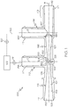
- FIGS. 1 and 2 illustrate different views of an aspirator 100.
- the aspirator 100 may be used in an engine, for example, in a vehicle's engine to provide vacuum to a device.
- the aspirator 100 is connected to a device requiring vacuum 102, and the aspirator 100 creates vacuum for said device 102 by the flow of air through a passageway 104, extending generally the length of the aspirator, designed to create the Venturi effect.
- Aspirator 100 includes a body 106 defining passageway 104 and having three or more ports that are connectable to an engine or components connected thereto.
- the ports include: (1) a motive port 108, which may be connected to a source of clean air, e.g., from the engine intake air cleaner, that is positioned upstream of a throttle; (2) a suction port 110, which can connect via an optional check valve 111 to the device requiring vacuum 102; (3) an aspirator outlet 112, which is connected to an engine intake manifold downstream of the throttle of the engine; and, optionally, (4) a bypass port 114.
- Each of the respective ports 108, 110, 112, and 114 may include a connector feature 117 on the outer surface thereof for connecting the respective port to a hose or other component in the engine.
- Check valve 111 is preferably arranged to prevent fluid from flowing from the suction port 110 to the application device 102.
- the device requiring vacuum 102 is a vehicle brake boost device, positive crankcase ventilation (PCV) device, or fuel purge device.
- the device requiring vacuum 102 is a hydraulic valve.
- the bypass port 114 may be connected to the device requiring vacuum 102 and, optionally, may include a check valve 120 in the fluid flow path 122 therebetween.
- Check valve 120 is preferably arranged to control the flow of fluid to or from the bypass port 114 to the application device 102.
- the aspirator 100 is generally a "T-shaped" aspirator defining an inner passageway along a central longitudinal axis B bisected by the suction port 110.
- the inner passageway 104 includes a first tapering portion 128 (also referred to herein as the motive cone) in the motive section 116 of the body 106 coupled to a second tapering portion 129 (also referred to herein as the discharge cone) in the discharge section 146 of the body 106.
- first tapering portion 128 and the second tapering portion 129 are aligned end to end having the motive outlet end 132 facing the discharge inlet end 134 and defining a Venturi gap 152 therebetween, which defines a fluid junction placing the suction port 110 in fluid communication with both the motive section 116 and the discharge section 146 of the inner passageway 104.
- the Venturi gap 152 as used herein means the linear distance between the motive outlet end 132 and the discharge inlet end 134.
- the vehicle manufacturer When an aspirator, such as aspirator 100, is for use in a vehicle engine, the vehicle manufacturer typically selects the size of both the motive port 108 and aspirator outlet 112 based on the tubing/hose size available for connection of the aspirator to the engine or components thereof. Additionally, the vehicle manufacturer typically selects the maximum motive flow rate available for use in the aspirator, which in turn will dictate the area of the interior opening defined at the motive outlet end 132, i.e., the motive outlet 133. Accordingly, the vehicle manufacturer's selected parameters for the particular engine dictate the ratio of the motive outlet 133 to the aspirator outlet 112.
- the disclosed aspirators 100 significantly reduce the compromise between the desire to produce high suction flow rates at low (5 kPa to 30 kPa) source/discharge pressures and increased depth of vacuum at higher (30 kPa to 60 kPa) source discharge pressures.
- This reduction in the compromise is accomplished by changing the configuration for the motive outlet 133 and the discharge inlet 135 (defined by the discharge inlet end 134) to increase the perimeter of the inner passageway 104 at the motive outlet end 132 and the discharge inlet end 134, such as presented in FIGS. 5 and 6 .
- FIGS. 5A-5B and 6 at least the interior surface of the motive outlet end 132 (the motive outlet 135) and the interior surface of the discharge inlet end 134 (the discharge inlet 135) are ellipse-shaped, but may alternately have a polygonal form.
- the interior of the inner passageway 104 extending away from the motive outlet end 132 and away from the discharge inlet end 134, in opposite directions, from the Venturi gap 152, may be constructed to have the same general shape.
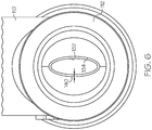
- FIG. 7 illustrates one embodiment of the shape of the internal passageway within the motive section of the aspirator, but equally, if rotated 180 degrees illustrates the internal passageway within the discharge section.
- the circular opening at the motive inlet end 130 is connected to the ellipse-shaped motive outlet 135 by hyperbola lines 170 that provide the advantage of flow lines at the motive outlet end 132 being parallel to one another.
- the motive inlet end 130 and the discharge outlet end 136 may also define ellipse-shaped or some other polygonal form openings at some point prior thereto and transition from said shapes to a circular cross-section to form a hose connecting portion, for example similar to hose-connecting portion 119, having connector features 117 on the exterior thereof.
- the suction port 110 has a central longitudinal axis C generally perpendicular to the body's central longitudinal axis B.
- the optional bypass port 114 may likewise have a central longitudinal axis D that is generally perpendicular to the body's central longitudinal axis B.
- the bypass port 114 may intersect the second tapering section 129 adjacent to, but downstream of the discharge outlet end 136.
- the body 106 may thereafter, i.e., downstream of this intersection of the bypass port, continue with a cylindrically uniform inner diameter until it terminates at the aspirator outlet 112.
- the bypass port 114 and/or the suction port 110 may be canted relative to axis B and/or to one another.
- the suction port 110 and the bypass port 114 are aligned with one another and have the same orientation relative to the body's central longitudinal axis B.
- the suction port 110 and the bypass port 114 may be offset from one another and can be positioned relative to components within the engine that they will connect to for ease of connection.
- the suction port 110 includes a suction inlet 138 and a suction outlet, which is the discharge inlet 134, and similarly to the first tapering section 128, may gradually, continuously taper as a cone or according to a hyperbolic function along its length from the larger dimensioned suction inlet 138 to a smaller dimensioned suction outlet 134.
- the bypass port 114 when present, may also gradually, continuously taper as a cone or according to a hyperbolic function along its length, in particular from a smaller dimensioned end 162 to a larger dimensioned end 160. Depending upon the attachment of the aspirator into a system, the bypass port 114 may operate with the larger dimensioned end 160 as the inlet and the smaller dimensioned end 162 as the outlet or vice versa.
- the suction port 110 includes an enlarged region defining a void 150 in fluid communication with Venturi gap 152 or conversely the Venturi gap 152 may be considered part of void 150.
- the fluid junction of the suction port 110 with inner passageway 104 is generally centered relative to the Venturi gap 152 and the void 150 is generally aligned with the suction port's central longitudinal axis C and transitions the first tapering portion 128 into the second tapering portion 129.
- the void 150 may be shaped as parallelepiped whose length is similar to the suction port's interior cross-section dimension(s), but whose bottom is an arcuate projection projecting downward away from the suction port 110.
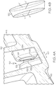
- the void In a cross-section taken transverse to the body's central longitudinal axis B along the suction port's central longitudinal axis C, the void is seen to be generally U-shaped around and/or over the discharge inlet end 134 and the motive outlet end 132 as best understood by viewing FIGS. 2 , 4A , and 5A in combination.
- the suction port extends downward around the sides of the motive outlet end 132 and the sides of the discharge inlet end 134 and defines the void 150 between all sides thereof.
- the exterior profile of the motive outlet end 132 and the discharge inlet end 134 both generally match their respective internal shapes.
- the flow of motive air through the first tapering portion 128 increases its speed, but creates low static pressure in the void 150.
- This low static pressure draws air from the suction port 110 into the Venturi gap 152 and into the discharge section 146 through the discharge inlet (suction outlet) 134.
- the aspirator 100 may be operated to meet the following geometric ratios: Representative Symbol Ratio A' suction inlet area / suction outlet area B' motive inlet area / motive outlet area C' discharge outlet area / discharge inlet area
- the ratio A' should be between 3 and 12, and the ratio B' should be greater than 4, and the ratio C' should be greater than 4.
- the ratio A' should be between 3 and 12, and the ratio B' should be greater than 4, and the ratio C' should be greater than 4.
- the outlet end of the motive cone and the inlet end of the discharge cone each have circular internal cross-sections and circular exterior profiles and thereby define a Venturi gap that is a frustum having a circular outer periphery. From this drawing one of the limitations to suction flow is illustrated - the area at the fluid junction of the suction port to the motive cone and the discharge cone.
- the area of the Venturi gap is increased by increasing the perimeter of the outlet end 132 and the inlet end 134 without increasing the overall inner dimension of the first tapering section 128 and the second tapering section 129 (preferably with no increase in the mass flow rate).
- motive outlet end 132 and discharge inlet end 134 are changed from being circular to being non-circular as described above.
- shapes that are not circular, each with a perimeter and a cross sectional area. These include polygons, or straight line segments connected to each other, non-circular curves, and even fractal curves. To minimize cost a curve is simpler and easy to manufacture and inspect, and has a desirable perimeter length.
- FIGS. 4A-AB and 5A-5B illustrate embodiments with improved fluid junctions where the suction port 110 meets the motive outlet end 132 and the discharge inlet end 134.
- the smallest area of the flow path from the suction port 110 to the Venturi gap 152 is the frustum defined between the motive outlet end 132 and the discharge inlet end 134, see FIGS. 4B and 5B .
- the outlet end 132 of the motive cone 128 and the inlet end 134 of the discharge cone 129 each have inner and outer elliptical perimeters and thereby define a Venturi gap 152 that is a frustum having an elliptical outer periphery.
- FIGS. 4A-AB and 5A-5B illustrate embodiments with improved fluid junctions where the suction port 110 meets the motive outlet end 132 and the discharge inlet end 134.
- the smallest area of the flow path from the suction port 110 to the Venturi gap 152 is the frustum defined between the motive outlet end 132 and the discharge in
- the outlet end 132 of the motive cone 128 and the inlet end 134 of the discharge cone 129 each have inner and outer generally rectangular-shaped perimeters (with rounded corners) and thereby define a Venturi gap 152 that is a frustum having a generally rectangular-shaped outer periphery. While the embodiments in the figures have the same perimeter for the outlet end 132 and the inlet end 134, i.e., both are elliptical or both are generally rectangular, the outlet end 132 and the inlet end 134 may have differently shaped perimeters, i.e., one may be elliptical while the other is generally rectangular. Additionally, the motive outlet end 132 and the discharge inlet end 134 may terminate with a rounded chamfer to improve the directionality of the flow of the fluid from the suction port 110 in to the discharge inlet end 134.
- the outlet end 132 of the motive cone 128 for each embodiment is dimensionally smaller than the inlet end 134 of the discharge cone 129. This difference in dimension is identified as offset 140.
- the offset is seen in that the length of the major axis Y of the motive outlet end 132 is less than the length of the major axis Y' of the discharge inlet end 134 and may also have a length of the minor axis X of the motive outlet end 132 that is less than the length of the minor axis X' of the discharge inlet end 134.
- the elliptical- or polygonal-shaped internal cross-section of the motive outlet end of the converging motive section has a ratio of the major axis to the minor axis of about 2 to about 4, and the elliptical- or polygonal-shaped internal cross-section of the inlet end of the diverging discharge section is offset, relative to the elliptical- or polygonal-shaped internal cross-section of the outlet end of the converging motive section, by the ratio of the difference of the discharge inlet area and the motive outlet area to the peak motive flow rate, which is then multiplied by a constant k 1 to have a unitless ratio of greater than 0.28.
- Offset ratio discharge inlet area ⁇ motive outlet area / peak motive flow rate * k 1
- k 1 c at the motive outlet end * D fluid at the motive outlet end
- c is the speed of sound
- D fluid is the density of the fluid (typically air).
- the Venturi gap between the motive outlet end and the discharge inlet end has a gap ratio defined as the area of the Venturi gap divided by the motive flow times a constant k 2 (to have a unitless ratio).
- the gap ratio is greater than 4.7.
- the elliptical- or polygonal-shaped internal cross-section of the motive outlet end 132 has an eccentricity of between 0 to, and including 1. In another embodiment, the elliptical- or polygonal-shaped internal cross-section of the outlet end has an eccentricity of between about 0.4 to, and including about 0.97.
- the outlet end 132 and the inlet end 134 are elliptical in profile thereby having a major axis (Y) and a minor axis (X).
- A is the distance from the origin to the ellipse along the major axis Y
- B is the distance from the origin to the ellipse along the minor axis X.
- the area is of 3.14 mm 2 with a perimeter of 6.28 mm.
- the ratio of perimeter to area is mathematically equal to 2 for a circular internal cross-section for the motive outlet end and the discharge inlet end.
- the perimeter can be increased while holding the cross sectional area fixed.
- This increase in perimeter provides the advantage of increasing the intersection area at the junction between the suction port, the motive cone, and the discharge cone, resulting in an increase in the suction port flow rate.
- the motive outlet end 132 and the discharge inlet end 134 are generally rectangular in profile thereby having a length and a width and hence two axes, a major axis A and a minor axis B.
- the aspirator's generally rectangular profile for the outlet end 132 and inlet end 134 include semicircular ends corresponding to the width of the rectangular portion.
- the orientation of the profile of the outlet and inlet ends 132, 134 should not be construed to be limited thereto.
- the area of this rectangle is equal to the sum of the areas of the two end semicircles plus the area of the straight section in between the semicircles.
- the perimeter of the rectangle is the lengths of the two sides plus the lengths of the semicircular ends.
- Another way to increase suction flow would be to lengthen the distance between the outlet end 132 of the motive cone 128 and the inlet end 134 of the discharge cone 129. As the motive flow travels through the Venturi gap it mixes with suction air. This combined flow has the effect of increasing the static pressure towards the discharge end of the Venturi. Lengthening this distance offers diminishing returns, and because the motive flow is largely unconstrained in the Venturi, offers the risk of turbulence and flow disturbance, which would reduce the velocity and increase static pressure. Accordingly, the increase in perimeter described above is preferred over lengthening the distance, but the two could be combined to avoid the diminishing returns.
- the aspirators disclosed herein may be molded as a monolithic body. In one embodiment, the aspirators are formed by injection molding.
- the Venturi gap 152 is a lineal distance proportional to the (motive mass flow rate) n , wherein n is 0.25 to 0.8, and the offset between the motive outlet and the discharge inlet is also proportional to the (motive mass flow rate) n , where n is 0.25 to 0.8, and the elliptical- or polygonal-shaped internal cross-section of the outlet end has an eccentricity of between 0 to, and including 1, or more preferably between about 0.4 to, and including about 0.97.
- n for the Venturi gap and n for the offset may both be 0.4 to 0.6.
- n for the Venturi gap and n for the offset are both 0.5 and the eccentricity is between about 0.4 to, and including 0.97.
- engine air i.e. filtered air
- Air exiting the aspirator at the discharge port can be connected to the engine air at a point where the pressure is lower than that of the motive port.
- the motion of the air from the motive to discharge port draws the air down the motive cone, which can be a straight cone or a hyperbolic profile as described above.
- the reduction in area causes the velocity of the air to increase. Because this is an enclosed space the laws of fluid mechanics state that the static pressure must decrease when the fluid velocity increases.
- the minimum cross sectional area of the motive cone abuts the Venturi gap.
- the discharge cone which is either a straight cone or a hyperbolic profile.
- the discharge region can continue as a straight or hyperbolic profile cone until it joins the discharge port, or it can transition to a simple cylindrical or tapered passage.
- the minimum cross sectional area end of the discharge cone is larger than that of the minimum cross section area end of the motive cone. The larger area is to provide area for the flow of air from the suction port. This change in area down the discharge cone slows the air velocity down again, with a subsequent increase in its static pressure.
- the Venturi gap connects to the suction port, which exposes air in the suction port/passage to the same low static pressure that exists in the air passing at high velocity between the motive and discharge cones.
- the pressure created here can be lower than the pressure at the discharge port, which is known already to be lower than that at the motive port.
- This low pressure may be used for a variety of applications on a vehicle, such as for evacuating a vehicle brake boost canister, as is known to those skilled in the art.
- the pressure at the discharge port is low enough to quickly lower the pressure at the application device. Since the area of the connection between the discharge cone or passage and the bypass passage is quite large relative to the connection between the suction passage and the Venturi gap, this optional connection can assist in evacuation of the application device initially.
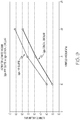
- a 3 gps aspirator having an elliptical motive outlet and an elliptical discharge inlet at the Venturi gap and a hyperboloid internal profile in the motive and discharge sections (referred to as the "hyperboloid ellipse aspirator") as illustrated in FIG. 7 was operated under conditions of 10 kPa manifold vacuum, 15 kPa manifold vacuum, and 20 kPa manifold vacuum with increasing brake boost canister vacuum and compared to a 3 gps conical circular aspirator under the same conditions.
- a conical circular aspirator is one that has a circular motive outlet and a circular discharge inlet and a conical internal profile in the motive and discharge sections.
- the hyperboloid ellipse aspirator provided a synergistic effect of the hyperboloid internal profile with the ellipse-shaped openings that exceeded the results of the conical circular aspirator.
- the hyperboloid ellipse aspirator provided higher suction flow rates over an increasing range of brake boost canister vacuum from 12 kPa to about 67 kPa.
- the hyperboloid ellipse aspirator performed generally similar to the conical circular aspirator when it was at 20 kPa manifold pressure, evidencing unexpected, superior performance.
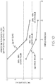
- the same aspirators compared for FIG. 8 were compared with respect to the ultimate vacuum the aspirator could generate and the time needed for the aspirator to evacuate a canister to create vacuum.
- the aspirator outlet 112 was in fluid communication with an intake manifold of the engine, the suction port was in fluid communication with a vehicle brake boost canister, and the motive inlet was connected to a source of clean air. As shown in the graph of FIG.
- the hyperboloid ellipse aspirator disclosed herein provides a deeper vacuum compared to the conical circular aspirator under the same operating conditions, i.e., at 10, 15, and 20 kPA of manifold vacuum the hyperboloid ellipse aspirator had an ultimate vacuum that was greater by at least 5 kPa.
- the hyperboloid ellipse aspirator was superior in evacuating a brake boost canister compared to the conical circular aspirator. At a manifold vacuum pressure of 10 kPa, the hyperboloid ellipse aspirator was over just under 4.5 seconds faster at evacuating the canister.
- the hyperboloid ellipse aspirator was about 2 seconds faster. Faster evacuation times at lower manifold vacuum provides for faster reaction time and improved performance. But, as seen in these graphs, not only does the aspirator with the hyperboloid elliptical profile have faster evacuation time, it also provides a deeper vacuum at manifold vacuums of 10, 15, and 20 kPa. This dual benefit was a surprising, unexpected result from changing the shapes of the motive outlet and the discharge inlet that defines the Venturi gap and using an internal passageway that changes/taper according to a hyperbolic function.
- One advantage of the aspirators disclosed herein is that a decreased amount of engine air is consumed/needed to generate the vacuum necessary to run a device requiring vacuum, which improves engine performance compared to that obtained with a vacuum pump or an aspirator with an internal circular profile.
Landscapes
- Engineering & Computer Science (AREA)
- Transportation (AREA)
- Mechanical Engineering (AREA)
- Jet Pumps And Other Pumps (AREA)
- Devices For Medical Bathing And Washing (AREA)
- Valves And Accessory Devices For Braking Systems (AREA)
Claims (14)
- Saugvorrichtung (100) umfassend:
einen Körper (106), der einen Venturi-Spalt zwischen einem Auslass-Ende eines zusammenlaufenden Antrieb-Abschnitts (116) und ein Einlass-Ende eines auseinanderlaufenden Auslass-Abschnitts (146) bildet; undeine Ansaug-Öffnung (110) in Fluidverbindung mit dem Venturi-Spalt (152); dadurch gekennzeichnet, dass der zusammenlaufende Antriebs-Abschnitt (116) einen kreisförmigen Antriebs-Einlass (130) bildet und einen ellipsen- oder polygonförmigen Antriebs-Auslass (133) bildet, undwobei der auseinanderlaufende Auslass-Abschnitt eine ellipsen- oder polygonförmige Auslass-Eingangsöffnung bildet;wobei der zusammenlaufende Antriebs-Abschnitt (116) einen inneren Durchgang bildet, der als eine hyperbolische Funktion verlaufend, von dem kreisförmigen Antriebs-Einlass (130) zum ellipsen- oder polygonförmigen Antriebs-Auslass (133) übergeht, und wobei der elliptischen- oder polygonal geformten Antriebs-Auslass (133) eine Fläche aufweist, die kleiner als die Fläche des kreisförmigen Antriebs-Einlasses (130) ist. - Saugvorrichtung gemäß Anspruch 1, wobei der auseinanderlaufende Auslass-Abschnitt ferner eine kreisförmige Auslass-Ausgangsöffnung bildet.
- Saugvorrichtung gemäß Anspruch 1, wobei sich die Ansaug-Öffnung nach unten um die Seiten des Auslass-Endes des zusammenlaufenden Antriebs-Abschnitts und die Seiten des Einlass-Endes des auseinanderlaufenden Auslass-Abschnitts erstreckt und einen Hohlraum zwischen all seinen Seiten bildet; und wobei das Außenprofil des Auslass-Endes des zusammenlaufenden Antriebs-Abschnitts und des Einlass-Endes des auseinanderlaufenden Auslass-Abschnitts im Allgemeinen deren jeweiligen inneren Form entspricht.
- Saugvorrichtung gemäß Anspruch 1, wobei das Einlass-Ende des auseinanderlaufenden Auslass-Abschnitts mit einer abgerundeten Abschrägung endet, die den Fluidstrom in die ellipsen- oder polygonförmige Auslass-Eingangsöffnung leitet.
- Saugvorrichtung gemäß Anspruch 1, wobei der ellipsen- oder polygonförmige Antriebs-Auslass eine Exzentrizität zwischen 0 und einschließlich 1 aufweist.
- Saugvorrichtung gemäß Anspruch 1, wobei der ellipsen- oder polygonförmige Antriebs-Auslass ein Hauptachsen- zu Nebenachsenverhältnis von etwa 2 bis etwa 4 aufweist und die ellipsen- oder polygonförmige Auslass-Eingangsöffnung gegenüber dem ellipsen- oder polygonförmigen Antriebs-Auslass versetzt ist um das Verhältnis der Differenz der Fläche der Auslass-Eingangsöffnung und der Fläche des Antriebs-Auslasses zum Spitzenwert der Antriebsflussrate ((Fläche der Auslass-Eingangsöffnung - Fläche des Antriebs-Auslasses) / Spitzenwert der Antriebsflussrate) mal einer Konstante, die größer ist als 0,28, wobei die Konstante gleich der Schallgeschwindigkeit mal der Dichte des Fluids am Antriebs-Auslass ist.
- Saugvorrichtung gemäß Anspruch 1, wobei der Venturi-Spalt proportional zum (Antriebs-Massendurchfluss)n ist, wobei n zwischen 0,25 und 0,8 ist.
- Saugvorrichtung gemäß Anspruch 1, der Venturi-Spalt proportional zum (Antriebs-Massendurchfluss)n ist, wobei n zwischen 0,4 und 0,6 ist.
- Saugvorrichtung gemäß Anspruch 8, wobei der ellipsen- oder polygonförmige Antriebs-Auslass eine Exzentrizität zwischen 0 und 1 einschließlich aufweist.
- Saugvorrichtung gemäß Anspruch 9, wobei der ellipsen- oder polygonförmige Antriebs-Auslass eine Exzentrizität zwischen etwa 0,4 und etwa 0,97 einschließlich aufweist.
- Saugvorrichtung gemäß Anspruch 1, wobei der Versatz zwischen dem Antriebs-Auslass und der Auslass-Eingangsöffnung proportional zum (Antriebs-Massendurchfluss)n ist, wobei n zwischen 0,25 bis 0,8 ist.
- Saugvorrichtung gemäß Anspruch 1, wobei der auseinanderlaufende Auslass-Abschnitt einen inneren Durchgang bildet, der in Form von hyperbolischen Kurven verläuft, der die Auslass-Eingangsöffnung mit einer Auslass-Ausgangsöffnung verbindet.
- Saugvorrichtung gemäß Anspruch 12, wobei der Antriebs-Auslass und die Auslass-Eingangsöffnung jeweils eine Exzentrizität zwischen etwa 0 und etwal einschließlich haben, und die Auslass-Eingangsöffnung relativ versetzt ist zur Antriebs-Auslass um einen Wert proportional zum (Antriebs-Massendurchfluss)n, wobei n zwischen 0,25 bis 0.8 ist.
- Saugvorrichtung gemäß Anspruch 1, wobei der Versatz zwischen dem Antriebs-Auslass und der Auslass-Eingangsöffnung proportional ist zum (Antriebs-Massendurchfluss)n, wobei n zwischen 0,4 bis 0,6 ist.
Applications Claiming Priority (3)
| Application Number | Priority Date | Filing Date | Title |
|---|---|---|---|
| US201361833746P | 2013-06-11 | 2013-06-11 | |
| US14/294,727 US9827963B2 (en) | 2013-06-11 | 2014-06-03 | Aspirators for producing vacuum using the Venturi effect |
| PCT/US2014/041250 WO2014200834A1 (en) | 2013-06-11 | 2014-06-06 | Aspirators for producing vacuum using the venturi effect |
Publications (3)
| Publication Number | Publication Date |
|---|---|
| EP3007949A1 EP3007949A1 (de) | 2016-04-20 |
| EP3007949A4 EP3007949A4 (de) | 2017-05-03 |
| EP3007949B1 true EP3007949B1 (de) | 2018-05-30 |
Family
ID=52004437
Family Applications (1)
| Application Number | Title | Priority Date | Filing Date |
|---|---|---|---|
| EP14811266.7A Active EP3007949B1 (de) | 2013-06-11 | 2014-06-06 | Absauger zur herstellung eines vakuums mithilfe des venturi-effekts |
Country Status (7)
| Country | Link |
|---|---|
| US (3) | US9827963B2 (de) |
| EP (1) | EP3007949B1 (de) |
| JP (1) | JP6470741B2 (de) |
| KR (1) | KR102074029B1 (de) |
| CN (1) | CN104309596B (de) |
| BR (1) | BR112015030922B1 (de) |
| WO (1) | WO2014200834A1 (de) |
Families Citing this family (37)
| Publication number | Priority date | Publication date | Assignee | Title |
|---|---|---|---|---|
| US9228785B2 (en) | 2010-05-04 | 2016-01-05 | Alexander Poltorak | Fractal heat transfer device |
| US20190277416A1 (en) * | 2012-02-20 | 2019-09-12 | Nyloncraft Incorporated | High mass flow check valve aspirator |
| US9827963B2 (en) * | 2013-06-11 | 2017-11-28 | Dayco Ip Holdings, Llc | Aspirators for producing vacuum using the Venturi effect |
| US10221867B2 (en) * | 2013-12-10 | 2019-03-05 | Dayco Ip Holdings, Llc | Flow control for aspirators producing vacuum using the venturi effect |
| CN105934616B (zh) | 2014-01-20 | 2018-02-02 | 戴科知识产权控股有限责任公司 | 具有改进的密封构件的止回阀 |
| CN106458190B (zh) | 2014-05-30 | 2019-12-06 | 戴科知识产权控股有限责任公司 | 具有喷射器、气动控制阀和可选择的吸气器的真空创建系统 |
| KR102217432B1 (ko) | 2014-06-06 | 2021-02-18 | 데이코 아이피 홀딩스 엘엘시 | 벤튜리 장치 및/또는 체크 밸브에서의 소음 감쇠 |
| BR112016028244B1 (pt) | 2014-06-09 | 2022-10-25 | Dayco Ip Holdings, Llc | Dispositivo venturi e sistema |
| KR102240986B1 (ko) * | 2014-07-10 | 2021-04-15 | 데이코 아이피 홀딩스 엘엘시 | 이중 벤튜리 장치 |
| US9732871B2 (en) | 2014-07-17 | 2017-08-15 | Dayco Ip Holdings, Llc | Aspirated relief valve for a turbocharging system |
| US9657748B2 (en) | 2014-08-06 | 2017-05-23 | Dayco Ip Holdings, Llc | Pneumatically actuated vacuum pump having multiple venturi gaps and check valves |
| WO2016032843A1 (en) | 2014-08-27 | 2016-03-03 | Dayco Ip Holdings, Llc | Low-cost evacuator for an engine having tuned venturi gaps |
| US9581060B2 (en) | 2014-12-01 | 2017-02-28 | Dayco Ip Holdings, Llc | Evacuator system for supplying high suction vacuum or high suction flow rate |
| US9828953B2 (en) | 2014-12-01 | 2017-11-28 | Dayco Ip Holdings, Llc | Evacuator system having multi-port evacuator |
| KR102255542B1 (ko) | 2015-01-09 | 2021-05-24 | 데이코 아이피 홀딩스 엘엘시 | 크랭크케이스를 환기하는 흡출기 |
| US10151283B2 (en) * | 2015-02-25 | 2018-12-11 | Dayco Ip Holdings, Llc | Evacuator with motive fin |
| WO2016145078A1 (en) * | 2015-03-09 | 2016-09-15 | Dayco Ip Holdings, Llc | Devices for producing vacuum using the venturi effect |
| BR112017022110B1 (pt) * | 2015-04-13 | 2023-03-21 | Dayco Ip Holdings, Llc | Dispositivos para produção de vácuo utilizando o efeito venturi e sistema incluindo um dispositivo para produzir vácuo utilizando o efeito venturi |
| US9816532B2 (en) * | 2015-06-11 | 2017-11-14 | Ford Global Technologies, Llc | Aspirator for internal combustion engine having integrated flow bypass and check valve |
| KR102400685B1 (ko) * | 2015-06-23 | 2022-05-20 | 데이코 아이피 홀딩스 엘엘시 | 벤튜리 장치 또는 체크 밸브를 몰딩 후 처리하는 방법 |
| EP3325817B1 (de) * | 2015-07-17 | 2021-03-03 | Dayco IP Holdings, LLC | Vorrichtungen zur herstellung eines vakuums mithilfe des venturi-effekts mit mehreren unterdurchgängen und antriebsausgängen im antriebsabschnitt |
| BR112018004023B1 (pt) * | 2015-08-28 | 2022-09-20 | Dayco Ip Holdings, Llc | Restritores utilizando o efeito venturi |
| US10190455B2 (en) * | 2015-10-28 | 2019-01-29 | Dayco Ip Holdings, Llc | Venturi devices resistant to ice formation for producing vacuum from crankcase gases |
| US9802591B2 (en) | 2015-11-13 | 2017-10-31 | Ford Global Technologies, Llc | Method and system for an aspirator for a brake booster |
| US9796368B2 (en) | 2015-11-13 | 2017-10-24 | Ford Global Technologies, Llc | Method and system for an aspirator for a brake booster |
| US9885296B2 (en) | 2015-11-18 | 2018-02-06 | Ford Global Technologies, Llc | Method and system for vacuum generation using a throttle body comprising a slidable throttle valve |
| US10060365B2 (en) | 2015-11-18 | 2018-08-28 | Ford Global Technologies, Llc | Method and system for vacuum generation using a throttle body comprising a slidable throttle valve |
| WO2018013668A1 (en) | 2016-07-12 | 2018-01-18 | Alexander Poltorak | System and method for maintaining efficiency of a heat sink |
| EP3516275B1 (de) * | 2016-09-21 | 2021-06-23 | Dayco IP Holdings, LLC | Ventilschieber mit in einem venturispalt einer venturivorrichtung zur vakuumerzeugung |
| WO2018156590A1 (en) * | 2017-02-21 | 2018-08-30 | Dlhbowles, Inc. | Vacuum generator/amplifier for gas applications and brake booster generation method |
| EP3685041B1 (de) | 2017-09-21 | 2023-05-10 | Dayco IP Holdings, LLC | Elektromagnetisch betätigte vakuumpumpe für ein motorsystem und system damit |
| KR101883766B1 (ko) | 2018-01-10 | 2018-08-30 | 강명호 | 아스피레이터 |
| US11415086B2 (en) | 2020-09-07 | 2022-08-16 | Dayco Ip Holdings, Llc | Three port, five-way magnetically latching valve for fuel vapor management systems and systems incorporating same |
| EP4210985A1 (de) | 2020-09-07 | 2023-07-19 | Dayco IP Holdings, LLC | Magnetisch verriegelbares ventil für kraftstoffdampfverwaltungssysteme und systeme damit |
| US11408380B2 (en) | 2020-12-24 | 2022-08-09 | Dayco Ip Holdings, Llc | Devices for producing vacuum using the Venturi effect having a hollow fletch |
| US11614098B2 (en) | 2020-12-24 | 2023-03-28 | Dayco Ip Holdings, Llc | Devices for producing vacuum using the Venturi effect having a solid fletch |
| WO2022178346A1 (en) | 2021-02-22 | 2022-08-25 | Dayco Ip Holdings, Llc | System and methods for a fuel tank pressure control pump |
Family Cites Families (32)
| Publication number | Priority date | Publication date | Assignee | Title |
|---|---|---|---|---|
| US1845969A (en) | 1928-04-02 | 1932-02-16 | Trico Products Corp | Suction augmenting device |
| US3234932A (en) | 1960-09-19 | 1966-02-15 | Forrest M Bird | Respirator |
| US3754841A (en) | 1971-05-14 | 1973-08-28 | Bendix Corp | Vacuum intensified brake booster system |
| DE2717685C3 (de) | 1977-04-21 | 1981-04-02 | Audi Nsu Auto Union Ag, 7107 Neckarsulm | Brennkraftmaschine für Kraftfahrzeuge |
| US4499034A (en) | 1982-09-02 | 1985-02-12 | The United States Of America As Represented By The United States Department Of Energy | Vortex-augmented cooling tower-windmill combination |
| US4554786A (en) | 1982-09-16 | 1985-11-26 | Nissin Kogyo Kabushiki Kaisha | Vacuum source device for vacuum booster for vehicles |
| AU545569B2 (en) | 1982-09-16 | 1985-07-18 | Honda Giken Kogyo Kabushiki Kaisha | Vacuum source device |
| US4519423A (en) * | 1983-07-08 | 1985-05-28 | University Of Southern California | Mixing apparatus using a noncircular jet of small aspect ratio |
| US5108266A (en) | 1991-05-29 | 1992-04-28 | Allied-Signal Inc. | Check valve with aspirating function |
| US5188141A (en) | 1991-12-03 | 1993-02-23 | Siemens Automotive Limited | Vacuum boost valve |
| US5291916A (en) | 1992-12-28 | 1994-03-08 | Excel Industries, Inc. | Check valve |
| DE4310761C2 (de) | 1993-04-01 | 1995-10-12 | Kayser A Gmbh & Co Kg | Strahlpumpe |
| DE69535095D1 (de) * | 1995-02-23 | 2006-08-10 | Ecolab Inc | Vorrichtung zum austeilen von gebrauchsfertiger visköser lösung sowie deren verwendung zum austeilen |
| US6035881A (en) | 1997-05-15 | 2000-03-14 | Walter Alfmeier Ag Prazisions-Baugruppenelemente | Checkvalve unit |
| JP2001295800A (ja) * | 1999-12-08 | 2001-10-26 | Myotoku Ltd | エゼクタ式真空発生器 |
| KR20030021636A (ko) * | 2001-09-07 | 2003-03-15 | 현대자동차주식회사 | 차량용 브레이크시스템의 보조진공장치 |
| US20060016477A1 (en) | 2004-07-23 | 2006-01-26 | Algis Zaparackas | Vacuum enhancing check valve |
| SE528482C2 (sv) | 2005-05-25 | 2006-11-28 | Gm Global Tech Operations Inc | Bromsservosystem i en förbränningsmotor av typ Otto |
| KR100767486B1 (ko) | 2006-06-26 | 2007-10-17 | 현대자동차주식회사 | 차량용 브레이크 부압 증폭기 |
| JP2008128150A (ja) | 2006-11-23 | 2008-06-05 | Aisan Ind Co Ltd | エゼクタおよびそれを用いたブレーキブースタ用負圧供給装置 |
| KR100941808B1 (ko) * | 2008-07-11 | 2010-02-10 | 현대자동차주식회사 | 브레이크 부스터 부압 조절 장치 |
| US20110186151A1 (en) | 2010-02-04 | 2011-08-04 | Bernard Joseph Sparazynski | Check valve |
| US8925520B2 (en) | 2010-03-10 | 2015-01-06 | Ford Global Technologies, Llc | Intake system including vacuum aspirator |
| US10337628B2 (en) | 2012-02-20 | 2019-07-02 | Nyloncraft Incorporated | High mass flow check valve aspirator |
| US9022007B2 (en) | 2012-03-09 | 2015-05-05 | Ford Global Technologies, Llc | Throttle valve system for an engine |
| US8783231B2 (en) | 2012-03-12 | 2014-07-22 | Ford Global Technologies, Llc | Venturi for vapor purge |
| US9827963B2 (en) * | 2013-06-11 | 2017-11-28 | Dayco Ip Holdings, Llc | Aspirators for producing vacuum using the Venturi effect |
| WO2016032843A1 (en) * | 2014-08-27 | 2016-03-03 | Dayco Ip Holdings, Llc | Low-cost evacuator for an engine having tuned venturi gaps |
| KR102255542B1 (ko) * | 2015-01-09 | 2021-05-24 | 데이코 아이피 홀딩스 엘엘시 | 크랭크케이스를 환기하는 흡출기 |
| US10151283B2 (en) * | 2015-02-25 | 2018-12-11 | Dayco Ip Holdings, Llc | Evacuator with motive fin |
| BR112017022110B1 (pt) * | 2015-04-13 | 2023-03-21 | Dayco Ip Holdings, Llc | Dispositivos para produção de vácuo utilizando o efeito venturi e sistema incluindo um dispositivo para produzir vácuo utilizando o efeito venturi |
| KR102400685B1 (ko) * | 2015-06-23 | 2022-05-20 | 데이코 아이피 홀딩스 엘엘시 | 벤튜리 장치 또는 체크 밸브를 몰딩 후 처리하는 방법 |
-
2014
- 2014-06-03 US US14/294,727 patent/US9827963B2/en active Active
- 2014-06-06 JP JP2016519556A patent/JP6470741B2/ja active Active
- 2014-06-06 EP EP14811266.7A patent/EP3007949B1/de active Active
- 2014-06-06 KR KR1020157035301A patent/KR102074029B1/ko active IP Right Grant
- 2014-06-06 BR BR112015030922-4A patent/BR112015030922B1/pt active IP Right Grant
- 2014-06-06 WO PCT/US2014/041250 patent/WO2014200834A1/en active Application Filing
- 2014-06-11 CN CN201410413220.7A patent/CN104309596B/zh active Active
-
2017
- 2017-10-24 US US15/791,561 patent/US10336305B2/en active Active
-
2019
- 2019-05-06 US US16/403,845 patent/US10525952B2/en active Active
Non-Patent Citations (1)
| Title |
|---|
| None * |
Also Published As
| Publication number | Publication date |
|---|---|
| BR112015030922A2 (de) | 2017-07-25 |
| WO2014200834A8 (en) | 2015-09-03 |
| US10336305B2 (en) | 2019-07-02 |
| US10525952B2 (en) | 2020-01-07 |
| US9827963B2 (en) | 2017-11-28 |
| JP6470741B2 (ja) | 2019-02-13 |
| EP3007949A1 (de) | 2016-04-20 |
| US20180043875A1 (en) | 2018-02-15 |
| CN104309596B (zh) | 2018-06-05 |
| CN104309596A (zh) | 2015-01-28 |
| EP3007949A4 (de) | 2017-05-03 |
| BR112015030922B1 (pt) | 2023-04-11 |
| WO2014200834A1 (en) | 2014-12-18 |
| US20190256070A1 (en) | 2019-08-22 |
| US20140360607A1 (en) | 2014-12-11 |
| KR20160018556A (ko) | 2016-02-17 |
| JP2016523200A (ja) | 2016-08-08 |
| KR102074029B1 (ko) | 2020-02-05 |
Similar Documents
| Publication | Publication Date | Title |
|---|---|---|
| EP3007949B1 (de) | Absauger zur herstellung eines vakuums mithilfe des venturi-effekts | |
| EP3516275B1 (de) | Ventilschieber mit in einem venturispalt einer venturivorrichtung zur vakuumerzeugung | |
| US10724550B2 (en) | Venturi devices with dual Venturi flow paths | |
| US10443627B2 (en) | Vacuum producing device having a suction passageway and a discharge passageway entering through the same wall | |
| EP3325817B1 (de) | Vorrichtungen zur herstellung eines vakuums mithilfe des venturi-effekts mit mehreren unterdurchgängen und antriebsausgängen im antriebsabschnitt | |
| EP3283025B1 (de) | Vorrichtung zur herstellung eines vakuums mithilfe des venturi-effekts | |
| CN108361438A (zh) | 旁通止回阀以及具有该旁通止回阀的文丘里装置 | |
| JP4347859B2 (ja) | オイルポンプ | |
| CN109311466B (zh) | 用于产生真空的装置中的旁通阀 | |
| US11408380B2 (en) | Devices for producing vacuum using the Venturi effect having a hollow fletch | |
| US20220205460A1 (en) | Devices for producing vacuum using the venturi effect having a solid fletch |
Legal Events
| Date | Code | Title | Description |
|---|---|---|---|
| PUAI | Public reference made under article 153(3) epc to a published international application that has entered the european phase |
Free format text: ORIGINAL CODE: 0009012 |
|
| 17P | Request for examination filed |
Effective date: 20160107 |
|
| AK | Designated contracting states |
Kind code of ref document: A1 Designated state(s): AL AT BE BG CH CY CZ DE DK EE ES FI FR GB GR HR HU IE IS IT LI LT LU LV MC MK MT NL NO PL PT RO RS SE SI SK SM TR |
|
| AX | Request for extension of the european patent |
Extension state: BA ME |
|
| DAX | Request for extension of the european patent (deleted) | ||
| A4 | Supplementary search report drawn up and despatched |
Effective date: 20170405 |
|
| RIC1 | Information provided on ipc code assigned before grant |
Ipc: B60T 13/52 20060101AFI20170330BHEP |
|
| GRAP | Despatch of communication of intention to grant a patent |
Free format text: ORIGINAL CODE: EPIDOSNIGR1 |
|
| INTG | Intention to grant announced |
Effective date: 20171215 |
|
| GRAS | Grant fee paid |
Free format text: ORIGINAL CODE: EPIDOSNIGR3 |
|
| GRAA | (expected) grant |
Free format text: ORIGINAL CODE: 0009210 |
|
| AK | Designated contracting states |
Kind code of ref document: B1 Designated state(s): AL AT BE BG CH CY CZ DE DK EE ES FI FR GB GR HR HU IE IS IT LI LT LU LV MC MK MT NL NO PL PT RO RS SE SI SK SM TR |
|
| REG | Reference to a national code |
Ref country code: GB Ref legal event code: FG4D |
|
| REG | Reference to a national code |
Ref country code: CH Ref legal event code: EP |
|
| REG | Reference to a national code |
Ref country code: AT Ref legal event code: REF Ref document number: 1003295 Country of ref document: AT Kind code of ref document: T Effective date: 20180615 |
|
| REG | Reference to a national code |
Ref country code: IE Ref legal event code: FG4D |
|
| REG | Reference to a national code |
Ref country code: DE Ref legal event code: R096 Ref document number: 602014026409 Country of ref document: DE |
|
| REG | Reference to a national code |
Ref country code: NL Ref legal event code: MP Effective date: 20180530 |
|
| REG | Reference to a national code |
Ref country code: LT Ref legal event code: MG4D |
|
| PG25 | Lapsed in a contracting state [announced via postgrant information from national office to epo] |
Ref country code: NO Free format text: LAPSE BECAUSE OF FAILURE TO SUBMIT A TRANSLATION OF THE DESCRIPTION OR TO PAY THE FEE WITHIN THE PRESCRIBED TIME-LIMIT Effective date: 20180830 Ref country code: FI Free format text: LAPSE BECAUSE OF FAILURE TO SUBMIT A TRANSLATION OF THE DESCRIPTION OR TO PAY THE FEE WITHIN THE PRESCRIBED TIME-LIMIT Effective date: 20180530 Ref country code: BG Free format text: LAPSE BECAUSE OF FAILURE TO SUBMIT A TRANSLATION OF THE DESCRIPTION OR TO PAY THE FEE WITHIN THE PRESCRIBED TIME-LIMIT Effective date: 20180830 Ref country code: SE Free format text: LAPSE BECAUSE OF FAILURE TO SUBMIT A TRANSLATION OF THE DESCRIPTION OR TO PAY THE FEE WITHIN THE PRESCRIBED TIME-LIMIT Effective date: 20180530 Ref country code: CY Free format text: LAPSE BECAUSE OF FAILURE TO SUBMIT A TRANSLATION OF THE DESCRIPTION OR TO PAY THE FEE WITHIN THE PRESCRIBED TIME-LIMIT Effective date: 20180530 Ref country code: ES Free format text: LAPSE BECAUSE OF FAILURE TO SUBMIT A TRANSLATION OF THE DESCRIPTION OR TO PAY THE FEE WITHIN THE PRESCRIBED TIME-LIMIT Effective date: 20180530 Ref country code: LT Free format text: LAPSE BECAUSE OF FAILURE TO SUBMIT A TRANSLATION OF THE DESCRIPTION OR TO PAY THE FEE WITHIN THE PRESCRIBED TIME-LIMIT Effective date: 20180530 |
|
| PG25 | Lapsed in a contracting state [announced via postgrant information from national office to epo] |
Ref country code: RS Free format text: LAPSE BECAUSE OF FAILURE TO SUBMIT A TRANSLATION OF THE DESCRIPTION OR TO PAY THE FEE WITHIN THE PRESCRIBED TIME-LIMIT Effective date: 20180530 Ref country code: GR Free format text: LAPSE BECAUSE OF FAILURE TO SUBMIT A TRANSLATION OF THE DESCRIPTION OR TO PAY THE FEE WITHIN THE PRESCRIBED TIME-LIMIT Effective date: 20180831 Ref country code: HR Free format text: LAPSE BECAUSE OF FAILURE TO SUBMIT A TRANSLATION OF THE DESCRIPTION OR TO PAY THE FEE WITHIN THE PRESCRIBED TIME-LIMIT Effective date: 20180530 Ref country code: LV Free format text: LAPSE BECAUSE OF FAILURE TO SUBMIT A TRANSLATION OF THE DESCRIPTION OR TO PAY THE FEE WITHIN THE PRESCRIBED TIME-LIMIT Effective date: 20180530 |
|
| REG | Reference to a national code |
Ref country code: AT Ref legal event code: MK05 Ref document number: 1003295 Country of ref document: AT Kind code of ref document: T Effective date: 20180530 |
|
| PG25 | Lapsed in a contracting state [announced via postgrant information from national office to epo] |
Ref country code: NL Free format text: LAPSE BECAUSE OF FAILURE TO SUBMIT A TRANSLATION OF THE DESCRIPTION OR TO PAY THE FEE WITHIN THE PRESCRIBED TIME-LIMIT Effective date: 20180530 |
|
| PG25 | Lapsed in a contracting state [announced via postgrant information from national office to epo] |
Ref country code: SK Free format text: LAPSE BECAUSE OF FAILURE TO SUBMIT A TRANSLATION OF THE DESCRIPTION OR TO PAY THE FEE WITHIN THE PRESCRIBED TIME-LIMIT Effective date: 20180530 Ref country code: RO Free format text: LAPSE BECAUSE OF FAILURE TO SUBMIT A TRANSLATION OF THE DESCRIPTION OR TO PAY THE FEE WITHIN THE PRESCRIBED TIME-LIMIT Effective date: 20180530 Ref country code: CZ Free format text: LAPSE BECAUSE OF FAILURE TO SUBMIT A TRANSLATION OF THE DESCRIPTION OR TO PAY THE FEE WITHIN THE PRESCRIBED TIME-LIMIT Effective date: 20180530 Ref country code: DK Free format text: LAPSE BECAUSE OF FAILURE TO SUBMIT A TRANSLATION OF THE DESCRIPTION OR TO PAY THE FEE WITHIN THE PRESCRIBED TIME-LIMIT Effective date: 20180530 Ref country code: AT Free format text: LAPSE BECAUSE OF FAILURE TO SUBMIT A TRANSLATION OF THE DESCRIPTION OR TO PAY THE FEE WITHIN THE PRESCRIBED TIME-LIMIT Effective date: 20180530 Ref country code: EE Free format text: LAPSE BECAUSE OF FAILURE TO SUBMIT A TRANSLATION OF THE DESCRIPTION OR TO PAY THE FEE WITHIN THE PRESCRIBED TIME-LIMIT Effective date: 20180530 Ref country code: PL Free format text: LAPSE BECAUSE OF FAILURE TO SUBMIT A TRANSLATION OF THE DESCRIPTION OR TO PAY THE FEE WITHIN THE PRESCRIBED TIME-LIMIT Effective date: 20180530 |
|
| REG | Reference to a national code |
Ref country code: CH Ref legal event code: PL |
|
| PG25 | Lapsed in a contracting state [announced via postgrant information from national office to epo] |
Ref country code: SM Free format text: LAPSE BECAUSE OF FAILURE TO SUBMIT A TRANSLATION OF THE DESCRIPTION OR TO PAY THE FEE WITHIN THE PRESCRIBED TIME-LIMIT Effective date: 20180530 Ref country code: IT Free format text: LAPSE BECAUSE OF FAILURE TO SUBMIT A TRANSLATION OF THE DESCRIPTION OR TO PAY THE FEE WITHIN THE PRESCRIBED TIME-LIMIT Effective date: 20180530 |
|
| REG | Reference to a national code |
Ref country code: DE Ref legal event code: R097 Ref document number: 602014026409 Country of ref document: DE |
|
| REG | Reference to a national code |
Ref country code: BE Ref legal event code: MM Effective date: 20180630 |
|
| REG | Reference to a national code |
Ref country code: IE Ref legal event code: MM4A |
|
| PG25 | Lapsed in a contracting state [announced via postgrant information from national office to epo] |
Ref country code: MC Free format text: LAPSE BECAUSE OF FAILURE TO SUBMIT A TRANSLATION OF THE DESCRIPTION OR TO PAY THE FEE WITHIN THE PRESCRIBED TIME-LIMIT Effective date: 20180530 Ref country code: LU Free format text: LAPSE BECAUSE OF NON-PAYMENT OF DUE FEES Effective date: 20180606 |
|
| PLBE | No opposition filed within time limit |
Free format text: ORIGINAL CODE: 0009261 |
|
| STAA | Information on the status of an ep patent application or granted ep patent |
Free format text: STATUS: NO OPPOSITION FILED WITHIN TIME LIMIT |
|
| GBPC | Gb: european patent ceased through non-payment of renewal fee |
Effective date: 20180830 |
|
| PG25 | Lapsed in a contracting state [announced via postgrant information from national office to epo] |
Ref country code: IE Free format text: LAPSE BECAUSE OF NON-PAYMENT OF DUE FEES Effective date: 20180606 Ref country code: CH Free format text: LAPSE BECAUSE OF NON-PAYMENT OF DUE FEES Effective date: 20180630 Ref country code: LI Free format text: LAPSE BECAUSE OF NON-PAYMENT OF DUE FEES Effective date: 20180630 Ref country code: FR Free format text: LAPSE BECAUSE OF NON-PAYMENT OF DUE FEES Effective date: 20180730 |
|
| 26N | No opposition filed |
Effective date: 20190301 |
|
| PG25 | Lapsed in a contracting state [announced via postgrant information from national office to epo] |
Ref country code: BE Free format text: LAPSE BECAUSE OF NON-PAYMENT OF DUE FEES Effective date: 20180630 Ref country code: SI Free format text: LAPSE BECAUSE OF FAILURE TO SUBMIT A TRANSLATION OF THE DESCRIPTION OR TO PAY THE FEE WITHIN THE PRESCRIBED TIME-LIMIT Effective date: 20180530 |
|
| PG25 | Lapsed in a contracting state [announced via postgrant information from national office to epo] |
Ref country code: GB Free format text: LAPSE BECAUSE OF NON-PAYMENT OF DUE FEES Effective date: 20180830 |
|
| PG25 | Lapsed in a contracting state [announced via postgrant information from national office to epo] |
Ref country code: AL Free format text: LAPSE BECAUSE OF FAILURE TO SUBMIT A TRANSLATION OF THE DESCRIPTION OR TO PAY THE FEE WITHIN THE PRESCRIBED TIME-LIMIT Effective date: 20180530 |
|
| PG25 | Lapsed in a contracting state [announced via postgrant information from national office to epo] |
Ref country code: MT Free format text: LAPSE BECAUSE OF NON-PAYMENT OF DUE FEES Effective date: 20180606 |
|
| PG25 | Lapsed in a contracting state [announced via postgrant information from national office to epo] |
Ref country code: TR Free format text: LAPSE BECAUSE OF FAILURE TO SUBMIT A TRANSLATION OF THE DESCRIPTION OR TO PAY THE FEE WITHIN THE PRESCRIBED TIME-LIMIT Effective date: 20180530 |
|
| PG25 | Lapsed in a contracting state [announced via postgrant information from national office to epo] |
Ref country code: PT Free format text: LAPSE BECAUSE OF FAILURE TO SUBMIT A TRANSLATION OF THE DESCRIPTION OR TO PAY THE FEE WITHIN THE PRESCRIBED TIME-LIMIT Effective date: 20180530 |
|
| PG25 | Lapsed in a contracting state [announced via postgrant information from national office to epo] |
Ref country code: HU Free format text: LAPSE BECAUSE OF FAILURE TO SUBMIT A TRANSLATION OF THE DESCRIPTION OR TO PAY THE FEE WITHIN THE PRESCRIBED TIME-LIMIT; INVALID AB INITIO Effective date: 20140606 Ref country code: MK Free format text: LAPSE BECAUSE OF NON-PAYMENT OF DUE FEES Effective date: 20180530 |
|
| PG25 | Lapsed in a contracting state [announced via postgrant information from national office to epo] |
Ref country code: IS Free format text: LAPSE BECAUSE OF FAILURE TO SUBMIT A TRANSLATION OF THE DESCRIPTION OR TO PAY THE FEE WITHIN THE PRESCRIBED TIME-LIMIT Effective date: 20180930 |
|
| P01 | Opt-out of the competence of the unified patent court (upc) registered |
Effective date: 20230522 |
|
| PGFP | Annual fee paid to national office [announced via postgrant information from national office to epo] |
Ref country code: DE Payment date: 20230628 Year of fee payment: 10 |