EP3006819B2 - Led-leuchte mit verstellbarem halteelement sowie anordnung zur lichtabgabe mit einer solchen led-leuchte - Google Patents
Led-leuchte mit verstellbarem halteelement sowie anordnung zur lichtabgabe mit einer solchen led-leuchte Download PDFInfo
- Publication number
- EP3006819B2 EP3006819B2 EP15188707.2A EP15188707A EP3006819B2 EP 3006819 B2 EP3006819 B2 EP 3006819B2 EP 15188707 A EP15188707 A EP 15188707A EP 3006819 B2 EP3006819 B2 EP 3006819B2
- Authority
- EP
- European Patent Office
- Prior art keywords
- led lamp
- retaining element
- lamp
- open position
- projection
- Prior art date
- Legal status (The legal status is an assumption and is not a legal conclusion. Google has not performed a legal analysis and makes no representation as to the accuracy of the status listed.)
- Active
Links
Images


Classifications
-
- F—MECHANICAL ENGINEERING; LIGHTING; HEATING; WEAPONS; BLASTING
- F21—LIGHTING
- F21S—NON-PORTABLE LIGHTING DEVICES; SYSTEMS THEREOF; VEHICLE LIGHTING DEVICES SPECIALLY ADAPTED FOR VEHICLE EXTERIORS
- F21S8/00—Lighting devices intended for fixed installation
- F21S8/03—Lighting devices intended for fixed installation of surface-mounted type
- F21S8/038—Lighting devices intended for fixed installation of surface-mounted type intended to be mounted on a light track
-
- F—MECHANICAL ENGINEERING; LIGHTING; HEATING; WEAPONS; BLASTING
- F21—LIGHTING
- F21S—NON-PORTABLE LIGHTING DEVICES; SYSTEMS THEREOF; VEHICLE LIGHTING DEVICES SPECIALLY ADAPTED FOR VEHICLE EXTERIORS
- F21S4/00—Lighting devices or systems using a string or strip of light sources
- F21S4/20—Lighting devices or systems using a string or strip of light sources with light sources held by or within elongate supports
- F21S4/28—Lighting devices or systems using a string or strip of light sources with light sources held by or within elongate supports rigid, e.g. LED bars
-
- F—MECHANICAL ENGINEERING; LIGHTING; HEATING; WEAPONS; BLASTING
- F21—LIGHTING
- F21V—FUNCTIONAL FEATURES OR DETAILS OF LIGHTING DEVICES OR SYSTEMS THEREOF; STRUCTURAL COMBINATIONS OF LIGHTING DEVICES WITH OTHER ARTICLES, NOT OTHERWISE PROVIDED FOR
- F21V21/00—Supporting, suspending, or attaching arrangements for lighting devices; Hand grips
- F21V21/14—Adjustable mountings
-
- F—MECHANICAL ENGINEERING; LIGHTING; HEATING; WEAPONS; BLASTING
- F21—LIGHTING
- F21V—FUNCTIONAL FEATURES OR DETAILS OF LIGHTING DEVICES OR SYSTEMS THEREOF; STRUCTURAL COMBINATIONS OF LIGHTING DEVICES WITH OTHER ARTICLES, NOT OTHERWISE PROVIDED FOR
- F21V21/00—Supporting, suspending, or attaching arrangements for lighting devices; Hand grips
- F21V21/34—Supporting elements displaceable along a guiding element
- F21V21/35—Supporting elements displaceable along a guiding element with direct electrical contact between the supporting element and electric conductors running along the guiding element
-
- F—MECHANICAL ENGINEERING; LIGHTING; HEATING; WEAPONS; BLASTING
- F21—LIGHTING
- F21V—FUNCTIONAL FEATURES OR DETAILS OF LIGHTING DEVICES OR SYSTEMS THEREOF; STRUCTURAL COMBINATIONS OF LIGHTING DEVICES WITH OTHER ARTICLES, NOT OTHERWISE PROVIDED FOR
- F21V21/00—Supporting, suspending, or attaching arrangements for lighting devices; Hand grips
- F21V21/02—Wall, ceiling, or floor bases; Fixing pendants or arms to the bases
- F21V21/025—Elongated bases having a U-shaped cross section
-
- F—MECHANICAL ENGINEERING; LIGHTING; HEATING; WEAPONS; BLASTING
- F21—LIGHTING
- F21Y—INDEXING SCHEME ASSOCIATED WITH SUBCLASSES F21K, F21L, F21S and F21V, RELATING TO THE FORM OR THE KIND OF THE LIGHT SOURCES OR OF THE COLOUR OF THE LIGHT EMITTED
- F21Y2103/00—Elongate light sources, e.g. fluorescent tubes
- F21Y2103/10—Elongate light sources, e.g. fluorescent tubes comprising a linear array of point-like light-generating elements
-
- F—MECHANICAL ENGINEERING; LIGHTING; HEATING; WEAPONS; BLASTING
- F21—LIGHTING
- F21Y—INDEXING SCHEME ASSOCIATED WITH SUBCLASSES F21K, F21L, F21S and F21V, RELATING TO THE FORM OR THE KIND OF THE LIGHT SOURCES OR OF THE COLOUR OF THE LIGHT EMITTED
- F21Y2115/00—Light-generating elements of semiconductor light sources
- F21Y2115/10—Light-emitting diodes [LED]
Definitions
- the invention relates to an LED lamp (LED: light-emitting diode) with a holding element for holding the lamp on a lamp carrier element, as well as a corresponding arrangement with such a lamp carrier element and such an LED lamp.
- LED light-emitting diode
- the support rail has a substantially U-shaped cross section that is open at the bottom. Electrical lines, which are used to supply the bar light with electricity, run inside the mounting rail.
- the bar light has a profile-like support element on which a retaining element is rotatably arranged, which is used to hold the bar light on the support rail.
- the holding element protrudes upwards beyond the carrier element of the bar light.
- the bar light is attached to the support rail from below, the holding element being inserted into the receiving area of the support rail formed by the U-shape of the support rail.
- the holding element is then rotated from an open position into a holding position. In the holding position, the bar light is arranged mechanically supported on the mounting rail.
- an electrical connection between the electrical lines of the support rail and the bar light is established by the holding element in the holding position.
- the holding element is moved from the holding position to the open position. As a result, the mechanical holder and also the electrical connection are canceled and the bar light can be easily removed from the mounting rail.
- Predecessor models of the bar light were equipped with fluorescent lamps as light sources instead of LEDs.
- the corresponding holding element was actuated from the underside of the bar luminaire.
- the holding element of the LED bar light therefore has an actuating arm which protrudes laterally from the carrier element of the bar light and can be actuated from the side.
- the actuating arm and the support element of the lamp are designed in such a way that in the holding position the actuating arm and thus the holding element as a whole are locked, so that the LED bar lamp is prevented from becoming detached from the mounting rail.
- the holding element To transport the LED bar light, the holding element is placed in the holding position, so that the holding element is prevented from twisting in an uncontrolled manner during transport. Therefore, in order to assemble the LED bar light, it is first necessary to move the holding element from the holding position into the open position.
- an LED bar light with a rotary tap element for holding the light on a mounting rail is known; the rotary tap element can be moved back and forth between a contacting position and an assembly position and has a laterally protruding actuating element.
- a safety device is used to secure the rotary tap element in the contacting position.
- the invention is based on the object of specifying a corresponding improved LED lamp or a corresponding improved arrangement for emitting light; In particular, easier handling when mounting the LED light on the light carrier element should be made possible.
- an LED lamp which has a holding element for holding the lamp on a lamp carrier element, the holding element relative to the rest of the LED lamp manually between a holding position that is used to hold the LED lamp on the lamp carrier -Element is used and an open position, which is used to release the bracket, is mounted so that it can move back and forth.
- the holding element has a projection which is designed to secure the open position.
- the holding element is held in the open position, in particular by static friction.
- a comparatively small amount of force is sufficient to adjust the holding element from the open position to the holding position during the assembly of the LED lamp on the lamp carrier element.
- no lock has to be released for this purpose.
- the holding element has an arm area which is designed to be elastic with respect to the rest of the holding element, the projection being designed on the arm area.
- the projection is preferably curved in a convex manner shaped. This makes it possible, in a particularly suitable manner, that only a small amount of force has to be applied to move the holding element out of the open position.
- the LED luminaire also has an elongated carrier element which extends along a longitudinal axis, the holding element being arranged on the carrier element such that it can rotate about an axis of rotation, in particular perpendicular to the longitudinal axis. Because of the elongated carrier element, the securing of the holding element in the open position is particularly suitable in this case.
- the carrier element preferably has a groove which extends in particular parallel to the longitudinal axis, the projection being arranged so as to engage in the groove in the open position of the holding element.
- the projection is guided particularly well during a movement of the holding element out of the open position.
- this design makes it possible to have a particularly suitable effect that, in an initial phase of the movement of the holding element out of the open position, a resistance to movement initially increases slightly, as a result of which the securing in the open position is particularly reliable.
- the arm region is preferably aligned in a first approximation parallel to the groove. In this way, particularly suitable force relationships for generating the fuse can be brought about.
- static friction is preferably brought about by the interaction between the projection and the groove. In this way it can be achieved in particular that only a small force has to be applied to move the holding element out of the open position. This is advantageous with regard to handling, in particular when installing the LED light on the light carrier element.
- the holding element has an actuating arm for manual adjustment of the holding element from the open position into the holding position. This enables particularly simple handling.
- the projection is arranged opposite the actuating arm with respect to the axis of rotation.
- the LED light is preferably designed in such a way that the holding element is secured in the holding position by a latching connection. As a result, the risk that the LED light mounted as intended on the light carrier element will come off unintentionally is particularly small.
- an arrangement for emitting light which has a light carrier element and an LED light according to the invention.
- the arrangement is preferably designed as a light strip system, the light carrier element being designed as a mounting rail and the LED light as a bar light.
- the holding element is preferably designed to form a mechanical and an electrical connection between the lamp carrier element and the LED lamp in the holding position. This enables particularly simple assembly of the LED light.
- the carrier element is preferably designed in the manner of a profile, it having a recess, in particular in the form of a feed-through opening, through which the actuating arm extends. This allows a protected and space-saving design as well as an advantageous design of the arrangement.
- the present invention relates to an LED lamp and an arrangement for emitting light with such an LED lamp and a lamp carrier element.
- the LED light hereinafter also referred to as “light” for short, can be in the form of an LED bar light and the light carrier element in the form of a support rail, the arrangement in particular representing a light strip system.
- a corresponding trunking system is as such, for example, from the Scriptures DE 10 2010 003 805 A1 known and unless otherwise shown below, the LED light and the arrangement can be designed, for example, as described in this document.
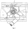
- Fig. 1 shows a perspective sketch of part of a lamp according to the invention.
- the lamp has an elongated carrier element 4 which extends along a longitudinal axis L.
- the carrier element 4 is preferably designed in the manner of a profile, so that the axis defined by the profile shape extends parallel to the longitudinal axis L.
- the luminaire is elongated overall, so that it extends along the longitudinal axis L.
- the luminaire can furthermore have an LED light source 8 which is arranged on the carrier element 4, as well as an optical element 9 for influencing a light generated by the LED light source 8;
- the optical element 9 is also preferably arranged on the carrier element 4.
- the lamp is intended to be mounted for operation on the lamp carrier element, here the mounting rail (not shown in the figures), in particular parallel to the mounting rail.
- the support rail preferably has a substantially U-shaped cross section that is open at the bottom. In particular, electrical lines that are used to supply power to the lamp are laid in the mounting rail.
- the lamp has a holding element 1 which is used to hold the lamp on the mounting rail.
- the holding element 1 is mounted so that it can be moved back and forth between a holding position and an open position manually with respect to the rest of the lamp, in particular with respect to the carrier element 4.
- the holding position is used to hold the lamp on the mounting rail.
- the open position is used to release this bracket. (In Fig. 2 the holding element 1 is not shown.)
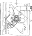
- Fig. 3 shows a sketch of a plan view of an area around the holding element 1, the holding element 1 being in the open position;
- Fig. 4 shows a corresponding sketch, the holding element 1 being in the holding position.
- the holding element 1 can have engagement elements 15 which, in the holding position for holding the lamp, grip over corresponding shoulder surfaces of the support rail. In the open position, on the other hand, the engagement elements 15 are not arranged above the shoulder surfaces, so that the lamp can be moved downwards unhindered and thus released from the support rail.
- the holding element 1 has an actuating arm 6 for manual adjustment of the holding element 1 from the open position into the holding position.
- the actuating arm 6 has in particular a grip area 65 for manual gripping, the grip area 65 preferably having a groove-shaped surface area for easier gripping.
- the carrier element 4 can preferably have a recess 7, in particular in the form of a feed-through opening, through which the actuating arm 6 extends, namely preferably both in the open position and in the holding position.
- the design is preferably such that the holding element 1 in the holding position forms both a mechanical and an electrical connection between the support rail and the lamp.
- the holding element 1 can have electrical contacts for this purpose, which are designed to contact the electrical lines running in the support rail in the holding position.
- the element corresponding to the holding element 1 shown here is therefore referred to as a "rotary tap”.
- the holding element 1 is arranged on the carrier element 2 such that it can rotate about an axis of rotation D, which is in particular oriented perpendicular to the longitudinal axis L.
- the axis of rotation D is preferably oriented vertically when the lamp is oriented relative to the vertical as intended for operation.
- the design is such that the holding element 1 can be rotated from the open position into the holding position by rotating about the axis of rotation D.
- a rotation through an angle that is between 20 ° and 80 °, in particular between 30 ° and 60 °, can be provided.
- the axis of rotation D runs transversely to the longitudinal axis L in a middle third with respect to the extent of the carrier element 4.
- the holding element 1 has a projection 2 which is used to secure the open position. In this way it can be achieved that the holding element 1 remains in the open position, even if the lamp is moved, for example during transport.
- the luminaire can be delivered to a user of the trunking system in a state in which the holding element is in the open position.
- the design is preferably such that, in the open position of the holding element 1, the interaction between the projection 2 and the carrier element 4 causes static friction, by which the holding element 1 is secured in its position in the open position.
- the projection 2 is initially guided a little along the carrier element 4, but then occurs in the further course of the movement due to the rotary movement of the holding element 1 free; A particularly small force is then sufficient to continue the movement into the holding position.
- the holding element 1 has an arm region 3 which is designed to be elastic or resilient with respect to the rest of the holding element 1, the projection 2 being formed on the arm region 3.
- the projection 2 presses elastically against the carrier element 4 in a particularly suitable manner and the open position is thus secured.
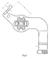
- Fig. 5 shows a perspective sketch of a separated lower sub-area of the holding element 1, this sub-area including both the actuating arm 6 and the arm area 3.
- Fig. 6 shows a sketch of a plan view of the separated lower portion.
- Particularly suitable force ratios can be achieved if the arm region 3 has a distance ⁇ from the axis of rotation D which is at least 25%, preferably at least 20% of the extent of the carrier element 4 transversely to the longitudinal axis L.
- the projection 2 is preferably convexly curved. In this way it can be achieved that the initiation of the release process, by means of which the holding element 1 is moved out of the open position, can be carried out particularly smoothly. A particularly suitable interaction between the projection 2 and the carrier element 4 can be brought about if the design is such that the convex curvature of the projection 2 presses against a surface area of the carrier element 4.
- the carrier element 4 preferably has a groove 5 which extends in particular parallel to the longitudinal axis L, the projection 2 being arranged to engage in the groove 5 in the open position of the holding element 1.
- the design is such that the projection 2 in the open position in a - in Fig. 3 - the direction R presses against the groove 5, which is directed perpendicular to the axis of rotation D, preferably at least substantially also perpendicular to the longitudinal axis L;
- the projection 2 preferably presses into the groove 5. In this way, the above-mentioned static friction between the projection 2 and the carrier element 4 can be brought about in a particularly suitable manner.
- a particularly suitable elastic abutment can be achieved if, in the open position, the arm region 3 is aligned parallel to the groove 5 or to the longitudinal axis L, at least in a first approximation.
- This design makes it possible, in particular, to initially increase the frictional force slightly when initiating the release process by which the holding element 1 is moved out of the open position, since the arm region 3 is deflected further out of its rest position. In this way, a particularly reliable securing of the open position can be achieved.
- This design also makes it possible that no separate structure has to be formed on the profile-like carrier element 4 in order to achieve the interaction between the projection 2 and the carrier element 4. This is advantageous in terms of production technology.
- the design is preferably also such that the arm region 3 with the projection 2 does not engage in the groove 5 when the holding element 1 is in the holding position.
- the arm region 3 preferably has a length ⁇ that is smaller than the distance ⁇ that is formed between the arm region 3 and the axis of rotation D.
- ⁇ that is formed between the arm region 3 and the axis of rotation D.
- the convex curvature of the projection 2 preferably has a radius of curvature which is smaller than 30% of the distance ⁇ , preferably smaller than 20%.
- the projection 2 is arranged opposite the actuating arm 6 or the grip area 65 with respect to the axis of rotation D.
- the lamp is preferably designed in such a way that the holding element 1 is secured in the holding position by a latching connection.
- the actuating arm 6 has a protrusion 61 for this purpose, in particular in the form of an elongated bead, which in the holding position interacts with an edge region of the recess 7 to form the latching connection.
- the bead is accordingly preferably aligned parallel to the longitudinal axis L.
Landscapes
- Engineering & Computer Science (AREA)
- General Engineering & Computer Science (AREA)
- Fastening Of Light Sources Or Lamp Holders (AREA)
- Non-Portable Lighting Devices Or Systems Thereof (AREA)
Description
- Die Erfindung betrifft eine LED-Leuchte (LED: Licht emittierende Diode) mit einem Halteelement zur Halterung der Leuchte an einem Leuchtenträger-Element, sowie eine entsprechende Anordnung mit einem solchen Leuchtenträger-Element und einer solchen LED-Leuchte.
- Die Anmelderin vertreibt unter dem Namen TECTON eine entsprechende Anordnung in Form eines Lichtbandsystems mit einer Tragschiene, die ein entsprechendes Leuchtenträger-Element darstellt, sowie mit einer LED-Balkenleuchte, die eine entsprechende LED-Leuchte darstellt. Die Tragschiene weist einen, im Wesentlichen U-förmigen, nach unten offenen Querschnitt auf. Im Inneren der Tragschiene verlaufen elektrische Leitungen, die zur elektrischen Versorgung der Balkenleuchte dienen. Die Balkenleuchte weist ein profilartiges Trägerelement auf, an dem drehbeweglich ein Halteelement angeordnet ist, das zur Halterung der Balkenleuchte an der Tragschiene dient. In der Schrift
DE 10 2010 003 805 A1 ist ein entsprechendes Lichtbandsystem beschrieben. - Das Halteelement ragt dabei nach oben über das Trägerelement der Balkenleuchte hinaus. Zur Verbindung der Balkenleuchte mit der Tragschiene wird die Balkenleuchte von unten an der Tragschiene angesetzt, wobei das Halteelement in den durch die U-Form der Tragschiene gebildeten Aufnahmebereich der Tragschiene eingeführt wird. Anschließend wird das Halteelement aus einer Offen-Position in eine Halte-Position gedreht. In der Halte-Position ist die Balkenleuchte mechanisch an der Tragschiene gehaltert angeordnet. Außerdem ist durch das Halteelement in der Halte-Position eine elektrische Verbindung zwischen den elektrischen Leitungen der Tragschiene und der Balkenleuchte hergestellt. Zum Abnehmen der Balkenleuchte von der Tragschiene wird das Halteelement aus der Halte-Position in die Offen-Position verstellt. Hierdurch wird die mechanische Halterung und auch die elektrische Verbindung aufgehoben und die Balkenleuchte kann ohne Weiteres von der Tragschiene entfernt werden.
- Vorgänger-Modelle der Balkenleuchte waren anstelle von LEDs mit Leuchtstofflampen als Lichtquellen ausgestattet. Bei diesen Leuchten erfolgte die Betätigung des entsprechenden Halteelements von der Unterseite der Balkenleuchte her. Im Fall der LED-Balkenleuchte wäre eine solche Gestaltung jedoch ungeeignet, da für eine gleichmäßige Lichtabgabe im Fall von LEDs in der Regel erwünscht ist, dass Letztere in einer quasi kontinuierlichen Reihe über die gesamte Länge der Leuchte hinweg angeordnet sind. Deshalb weist das Halteelement der LED-Balkenleuchte einen Betätigungsarm auf, der seitlich aus dem Trägerelement der Balkenleuchte herausragt und von der Seite her betätigt werden kann. Der Betätigungsarm und das Trägerelement der Leuchte sind dabei derart gestaltet, dass in der Halte-Position der Betätigungsarm und damit das Halteelement als Ganzes verriegelt ist, so dass ein selbstständiges Lösen der LED-Balkenleuchte von der Tragschiene verhindert ist.
- Für einen Transport der LED-Balkenleuchte wird das Halteelement in die Halte-Position gestellt, so dass verhindert ist, dass sich das Halteelement während des Transports unkontrolliert verdreht. Daher ist es zur Montage der LED-Balkenleuchte zunächst erforderlich, das Halteelement aus der Halte-Position in die Offen-Position zu verstellen.
- Aus der
DE 20 2012 100 629 U1 ist eine LED-Balkenleuchte mit einem Drehabgriffs-Element zur Halterung der Leuchte an einer Tragschiene bekannt; das Drehabgriffs-Element ist zwischen einer Kontaktierungsposition und einer Montageposition hin-und her bewegbar und weist ein seitlich abstehendes Betätigungselement auf. Dabei dient zur Sicherung des Drehabgriff-Elements in der Kontaktierungsposition eine Sicherungseinrichtung. - Der Erfindung liegt die Aufgabe zugrunde, eine entsprechende verbesserte LED-Leuchte bzw. eine entsprechende verbesserte Anordnung zur Lichtabgabe anzugeben; insbesondere soll eine erleichterte Handhabung beim Montieren der LED-Leuchte an dem Leuchtenträger-Element ermöglicht sein.
- Diese Aufgabe wird gemäß der Erfindung mit den in den unabhängigen Ansprüchen genannten Gegenständen gelöst. Besondere Ausführungsarten der Erfindung sind in den abhängigen Ansprüchen angegeben.
- Gemäß der Erfindung ist eine LED-Leuchte vorgesehen, die ein Halteelement zur Halterung der Leuchte an einem Leuchtenträger-Element aufweist, wobei das Halteelement gegenüber der restlichen LED-Leuchte manuell zwischen einer Halte-Position, die zur Halterung der LED-Leuchte an dem Leuchtenträger-Element dient und einer Offen-Position, die zum Lösen der Halterung dient, hin- und her beweglich gelagert ist. Das Halteelement weist dabei einen Vorsprung auf, der zur Sicherung der Offen-Position ausgestaltet ist.
- Durch diese Gestaltung lässt sich herstellungstechnisch vorteilhaft erzielen, dass das Halteelement in der Offen-Position gehalten ist, insbesondere durch Haftreibung. Zum Verstellen des Halteelements aus der Offen-Position in die Halte-Position im Rahmen der Montage der LED-Leuchte an dem Leuchtenträger-Element ist ein vergleichsweise geringer Kraftaufwand ausreichend. Es muss hierzu insbesondere keine Verriegelung gelöst werden.
- Erfindungsgemäß weist das Halteelement einen Armbereich auf, der elastisch gegenüber dem restlichen Halteelement ausgebildet ist, wobei der Vorsprung an dem Armbereich ausgebildet ist. Hierdurch lassen sich besonders geeignete Kraftverhältnisse für die Sicherung des Halteelements in der Offen-Position erzielen. Insbesondere lässt sich auf diese Weise die Wahrscheinlichkeit dafür verringern, dass sich das Halteelement im Fall einer Erschütterung oder dergleichen ungewollt aus der Offen-Position heraus bewegt.
- Vorzugsweise ist der Vorsprung konvex gewölbt geformt. Hierdurch lässt sich besonders geeignet bewirken, dass zum Bewegen des Halteelements aus der Offen-Position lediglich ein geringer Kraftaufwand aufgebracht werden muss.
- Erfindungsgemäß weist die LED-Leuchte außerdem ein längliches Trägerelement auf, das sich entlang einer Längsachse erstreckt, wobei das Halteelement um eine, insbesondere senkrecht zu der Längsachse orientierte Drehachse drehbeweglich an dem Trägerelement angeordnet ist. Aufgrund des länglichen Trägerelements eignet sich die Sicherung des Halteelements in der Offen-Position in diesem Fall besonders.
- Vorzugsweise weist dabei das Trägerelement eine Nut auf, die sich insbesondere parallel zu der Längsachse erstreckt, wobei in der Offen-Position des Halteelements der Vorsprung in die Nut eingreifend angeordnet ist. Hierdurch lässt sich erzielen, dass der Vorsprung während einer Bewegung des Halteelements aus der Offen-Position heraus besonders gut geführt ist. Außerdem lässt sich durch diese Gestaltung besonders geeignet bewirken, dass in einer Anfangsphase der Bewegung des Halteelements aus der Offen-Position heraus ein Bewegungswiderstand zunächst geringfügig zunimmt, wodurch die Sicherung in der Offen-Position besonders zuverlässig ist.
- Vorzugsweise ist in der Offen-Position des Halteelements der Armbereich in erster Näherung parallel zu der Nut ausgerichtet. Hierdurch lassen sich besonders geeignete Kraftverhältnisse zur Erzeugung der Sicherung bewirken.
- Vorzugsweise ist in der Offen-Position des Halteelements durch die Wechselwirkung zwischen dem Vorsprung und der Nut eine Haftreibung bewirkt. Hierdurch lässt sich insbesondere erzielen, dass zum Bewegen des Halteelements aus der Offen-Position heraus lediglich eine geringe Kraft aufgewendet werden muss. Dies ist vorteilhaft mit Bezug auf die Handhabung, insbesondere bei der Montage der LED-Leuchte an dem Leuchtenträger-Element.
- Erfindungsgemäß weist das Halteelement einen Betätigungsarm zum manuellen Verstellen des Halteelements aus der Offen-Position in die Halte-Position auf. Hierdurch ist eine besonders einfache Handhabung ermöglicht.
- Erfindungsgemäß ist dabei der Vorsprung mit Bezug auf die Drehachse dem Betätigungsarm gegenüberliegend angeordnet.
- Vorzugsweise ist die LED-Leuchte derart gestaltet, dass das Halteelement in der Halte-Position durch eine Rastverbindung gesichert ist. Hierdurch ist die Gefahr, dass sich die an dem Leuchtenträger-Element wie vorgesehen montierte LED-Leuchte ungewollt löst, besonders klein.
- Gemäß einem weiteren Aspekt der Erfindung ist eine Anordnung zur Lichtabgabe vorgesehen, die ein Leuchtenträger-Element und eine erfindungsgemäße LED-Leuchte aufweist. Vorzugsweise ist dabei die Anordnung als Lichtbandsystem gestaltet, wobei das Leuchtenträger-Element als Tragschiene gestaltet ist und die LED-Leuchte als Balkenleuchte.
- Vorzugsweise ist das Halteelement dazu ausgestaltet, in der Halte-Position eine mechanische und eine elektrische Verbindung zwischen dem Leuchtenträger-Element und der LED-Leuchte zu bilden. Hierdurch ist eine besonders einfache Montage der LED-Leuchte ermöglicht.
- Vorzugsweise ist das Trägerelement profilartig gestaltet, wobei es eine Ausnehmung, insbesondere in Form einer Durchführungsöffnung aufweist, durch die sich der Betätigungsarm hindurch erstreckt. Dies erlaubt eine geschützte und dabei raumsparende Gestaltung sowie ein vorteilhaftes Design der Anordnung.
- Die Erfindung wird im Folgenden anhand eines Ausführungsbeispiels und mit Bezug auf die Zeichnungen näher erläutert. Es zeigen:
- Fig. 1
- eine perspektivische Skizze eines Bereichs um das Halteelement gemäß einem Ausführungsbeispiel einer erfindungsgemäßen LED-Leuchte,
- Fig. 2
- eine Skizze eines Querschnitts normal zu der Längsachse des Trägerelements der Leuchte, wobei das Trägerelement, die LED-Lichtquelle und ein optisches Element der Leuchte skizziert sind,
- Fig. 3
- eine Skizze einer Ansicht von oben, wobei sich das Halteelement in der Offen-Position befindet,
- Fig. 4
- eine Skizze einer Ansicht von oben, wobei sich das Halteelement in der Halte-Position befindet,
- Fig. 5
- eine perspektivische Skizze eines separierten unteren Teilbereichs des Halteelements und
- Fig. 6
- eine Skizze einer Aufsicht auf den separierten unteren Teilbereich.
- Die vorliegende Erfindung betrifft eine LED-Leuchte und eine Anordnung zur Lichtabgabe mit einer solchen LED-Leuchte und einem Leuchtenträger-Element. Insbesondere kann die LED-Leuchte, hier im Folgenden auch kurz als "Leuchte" bezeichnet, in Form einer LED-Balkenleuchte gegeben sein und das Leuchtenträger-Element in Form einer Tragschiene, wobei die Anordnung insbesondere ein Lichtbandsystem darstellt. Ein entsprechendes Lichtbandsystem ist als solches beispielsweise aus der Schrift
DE 10 2010 003 805 A1 bekannt und soweit im Folgenden nicht anders dargestellt, können die LED-Leuchte und die Anordnung beispielsweise so gestaltet sein wie in dieser Schrift beschrieben. -
Fig. 1 zeigt eine perspektivische Skizze eines Teils einer erfindungsgemäßen Leuchte. Im gezeigten Beispiel weist die Leuchte ein längliches Trägerelement 4 auf, das sich entlang einer Längsachse L erstreckt. Vorzugsweise ist das Trägerelement 4 profilartig gestaltet, so dass sich die durch die Profilform festgelegte Achse parallel zu der Längsachse L erstreckt. Dabei ist die Leuchte insgesamt länglich, so dass sie sich entlang der Längsachse L erstreckt. - In
Fig. 2 ist eine Skizze eines Querschnitts normal zu der Längsachse L skizziert; wie beispielhaft gezeigt, kann die Leuchte weiterhin eine LED-Lichtquelle 8 aufweisen, die an dem Trägerelement 4 angeordnet ist, sowie ein optisches Element 9 zur Beeinflussung eines von der LED-Lichtquelle 8 erzeugten Lichts; auch das optische Element 9 ist vorzugsweise an dem Trägerelement 4 angeordnet. - Die Leuchte ist dafür vorgesehen, zum Betrieb an dem Leuchtenträger-Element, hier der (in den Figuren nicht gezeigten) Tragschiene montiert zu werden, insbesondere parallel zu der Tragschiene. Die Tragschiene weist vorzugsweise einen im Wesentlichen U-förmigen Querschnitt auf, der nach unten offen ist. In der Tragschiene sind insbesondere elektrische Leitungen verlegt, die zur Stromversorgung der Leuchte dienen.
- Die Leuchte weist ein Halteelement 1 auf, das zur Halterung der Leuchte an der Tragschiene dient. Das Halteelement 1 ist gegenüber der restlichen Leuchte, insbesondere gegenüber dem Trägerelement 4 manuell zwischen einer Halte-Position und einer Offen-Position hin und her beweglich gelagert. Die Halte-Position dient dabei zur Halterung der Leuchte an der Tragschiene. Die Offen-Position dient zum Lösen dieser Halterung. (In
Fig. 2 ist das Halteelement 1 nicht eingezeichnet.) -
Fig. 3 zeigt eine Skizze einer Aufsicht auf einen Bereich um das Halteelement 1, wobei sich das Halteelement 1 in der Offen-Position befindet;Fig. 4 zeigt eine entsprechende Skizze, wobei sich das Halteelement 1 in der Halte-Position befindet. Beispielsweise kann das Halteelement 1 Eingreifelemente 15 aufweisen, die in der Halte-Position zur Halterung der Leuchte über entsprechende Schulterflächen der Tragschiene greifen. In der Offen-Position hingegen sind die Eingreifelemente 15 nicht über den Schulterflächen angeordnet, so dass die Leuchte ungehindert nach unten bewegt und so von der Tragschiene gelöst werden kann. - Erfindungsgemäß weist das Halteelement 1 einen Betätigungsarm 6 zum manuellen Verstellen des Halteelements 1 aus der Offen-Position in die Halte-Position auf. Der Betätigungsarm 6 weist insbesondere einen Griffbereich 65 zum manuellen Angriff auf, wobei der Griffbereich 65 vorzugsweise einen rillen-förmigen Oberflächenbereich zum erleichterten Angriff aufweist. Dabei kann das Trägerelement 4 vorzugsweise eine Ausnehmung 7, insbesondere in Form einer Durchführungsöffnung aufweisen, durch die sich der Betätigungsarm 6 hindurch erstreckt, und zwar vorzugsweise sowohl in der Offen-Position, als auch in der Halte-Position.
- Vorzugsweise ist die Gestaltung derart, dass das Halteelement 1 in der Halte-Position sowohl eine mechanische, als auch eine elektrische Verbindung zwischen der Tragschiene und der Leuchte bildet. Insbesondere kann das Halteelement 1 hierzu elektrische Kontakte aufweisen, die dazu ausgebildet sind, in der Halte-Position die in der Tragschiene verlaufenden elektrischen Leitungen zu kontaktieren. In der erwähnten Schrift
DE 10 2010 003 805 A1 ist daher das zu dem hier gezeigten Halteelement 1 korrespondierende Element als "Drehabgriff" bezeichnet. - Das Halteelement 1 ist beim gezeigten Beispiel um eine, insbesondere senkrecht zu der Längsachse L orientierte Drehachse D drehbeweglich an dem Trägerelement 2 angeordnet. Vorzugsweise ist die Drehachse D vertikal orientiert, wenn die die Leuchte wie für einen Betrieb vorgesehen gegenüber der Vertikalen ausgerichtet ist. Insbesondere ist die Gestaltung derart, dass sich das Halteelement 1 durch eine Drehung um die Drehachse D aus der Offen-Position in die Halte-Position drehen lässt. Beispielsweise kann dabei eine Drehung um einen Winkel vorgesehen sein, der zwischen 20° und 80° beträgt, insbesondere zwischen 30° und 60°.
- Beim gezeigten Beispiel verläuft die Drehachse D mit Bezug auf die Erstreckung des Trägerelements 4 quer zur Längsachse L in einem mittleren Drittel.
- Das Halteelement 1 weist einen Vorsprung 2 auf, der zur Sicherung der Offen-Position dient. Auf diese Weise lässt sich erzielen, dass das Halteelement 1 in der Offen-Position verbleibt, auch wenn die Leuchte, beispielsweise bei einem Transport, bewegt wird. So lässt sich die Leuchte insbesondere in einem Zustand zu einem Nutzer des Lichtbandsystems liefern, in dem sich das Halteelement in der Offen-Position befindet. Insbesondere ist es dann für den Nutzer nicht erforderlich, zur Montage der Leuchte zunächst das Halteelement in die Offen-Position zu bewegen. Vielmehr kann die Leuchte unmittelbar von unten an der Tragschiene angesetzt werden und anschließend das Halteelement 1 aus der Offen-Position in die Halte-Position bewegt bzw. gedreht werden.
- Vorzugsweise ist die Gestaltung derart, dass in der Offen-Position des Halteelements 1 durch die Wechselwirkung zwischen dem Vorsprung 2 und dem Trägerelement 4 eine Haftreibung bewirkt ist, durch die das Halteelement 1 in der Offen-Position in seiner Lage gesichert ist.
- Wenn das Halteelement 1 aus der Offen-Position in die Halte-Position gedreht wird, wird beim gezeigten Beispiel der Vorsprung 2 zunächst ein Stück weit an dem Trägerelement 4 entlang geführt, kommt dann jedoch im weiteren Verlauf der Bewegung jedoch aufgrund der Drehbewegung des Halteelements 1 frei; zur Fortführung der Bewegung in die Halte-Position ist dann eine besonders geringe Kraft ausreichend.
- In der Offen-Position ist also insbesondere keine Verriegelung des Halteelements 1 gegeben; zum Bewegen des Halteelements 1 aus der Offen-Position in die Halte-Position ist also keine Verriegelung aufzuheben.
- Erfindungsgemäß weist das Halteelement 1 einen Armbereich 3 auf, der elastisch bzw. federnd gegenüber dem restlichen Halteelement 1 ausgebildet ist, wobei der Vorsprung 2 an dem Armbereich 3 ausgebildet ist. Hierdurch lässt sich erzielen, dass der Vorsprung 2 besonders geeignet elastisch gegen das Trägerelement 4 drückt und so die Offen-Position gesichert wird. Hierdurch lässt sich insbesondere erzielen, dass zum manuellen Bewegen bzw. Drehen des Halteelements 1 aus der Offen-Position in die Halte-Position lediglich eine vergleichsweise geringe Kraft ausgeübt werden muss, aber die Offen-Position dennoch gut gesichert ist.
-
Fig. 5 zeigt eine perspektivische Skizze eines separierten unteren Teilbereichs des Halteelements 1, wobei dieser Teilbereich sowohl den Betätigungsarm 6 umfasst, als auch den Armbereich 3.Fig. 6 zeigt eine Skizze einer Aufsicht auf den separierten unteren Teilbereich. Besonders geeignete Kraftverhältnisse lassen sich erzielen, wenn der Armbereich 3 von der Drehachse D einen Abstand δ aufweist, der wenigstens 25%, vorzugsweise wenigstens 20% der Erstreckung des Trägerelements 4 quer zur Längsachse L beträgt. - Weiterhin vorzugsweise ist der Vorsprung 2 konvex gewölbt geformt. Hierdurch lässt sich erzielen, dass die Einleitung des Lösevorgangs, durch den das Halteelement 1 aus der Offen-Position heraus bewegt wird, besonders leichtgängig zu bewerkstelligen ist. Eine besonders geeignete Wechselwirkung zwischen dem Vorsprung 2 und dem Trägerelement 4 lässt sich bewirken, wenn die Gestaltung derart ist, dass der Vorsprung 2 mit seiner konvexen Wölbung gegen einen Oberflächenbereich des Trägerelements 4 drückt.
- Wie im gezeigten Beispiel der Fall, weist das Trägerelement 4 vorzugsweise eine Nut 5 auf, die sich insbesondere parallel zu der Längsachse L erstreckt, wobei in der Offen-Position des Halteelements 1 der Vorsprung 2 in die Nut 5 eingreifend angeordnet ist. Insbesondere ist die Gestaltung hierbei derart, dass der Vorsprung 2 in der Offen-Position in einer - in
Fig. 3 bezeichneten - Richtung R gegen die Nut 5 drückt, die senkrecht zu der Drehachse D gerichtet ist, vorzugsweise zumindest im Wesentlichen auch senkrecht zu der Längsachse L; wie im gezeigten Beispiel der Fall, drückt hierbei der Vorsprung 2 vorzugsweise in die Nut 5 hinein. Hierdurch lässt sich die oben erwähnte Haftreibung zwischen dem Vorsprung 2 und dem Trägerelement 4 besonders geeignet bewirken. - Eine besonders geeignete elastische Anlage lässt sich erzielen, wenn in der Offen-Position der Armbereich 3 zumindest in erster Näherung parallel zu der Nut 5 bzw. zu der Längsachse L ausgerichtet ist. Durch diese Gestaltung lässt sich insbesondere erzielen, dass bei der Einleitung des Lösevorgangs, durch den das Halteelement 1 aus der Offen-Position heraus bewegt wird, die Reibungskraft zunächst geringfügig zunimmt, da der Armbereich 3 weiter aus seiner Ruheposition heraus ausgelenkt wird. Hierdurch lässt sich eine besonders zuverlässige Sicherung der Offen-Position erzielen.
- Diese Gestaltung ermöglicht außerdem, dass an dem profilartigen Trägerelement 4 keine gesonderte Struktur zur Erzielung der Wechselwirkung zwischen dem Vorsprung 2 und dem Trägerelement 4 ausgebildet werden muss. Dies ist herstellungstechnisch vorteilhaft.
- Vorzugsweise ist die Gestaltung weiterhin derart, dass der Armbereich 3 mit dem Vorsprung 2 nicht in die Nut 5 eingreift, wenn sich das Halteelement 1 in der Halte-Position befindet.
- Vorzugsweise weist hierzu der Armbereich 3 eine Länge λ auf, die kleiner ist als der Abstand δ, der zwischen dem Armbereich 3 und der Drehachse D gebildet ist. Insbesondere kann vorgesehen sein, dass hierbei die folgende Beziehung erfüllt ist: 1/4 δ ≤ λ ≤ 3/4 δ.
- Die konvexe Wölbung des Vorsprungs 2 weist vorzugsweise einen Krümmungsradius auf, der kleiner ist als 30% des Abstands δ, vorzugsweise kleiner als 20%.
- Wie beim gezeigten Beispiel der Fall, ist erfindungsgemäß der Vorsprung 2 mit Bezug auf die Drehachse D dem Betätigungsarm 6 bzw. dem Griffbereich 65 gegenüberliegend angeordnet.
- Weiterhin ist die Leuchte vorzugsweise derart gestaltet, dass das Halteelement 1 in der Halte-Position durch eine Rastverbindung gesichert ist. Im gezeigten Beispiel weist hierzu der Betätigungsarm 6 eine Vorwölbung 61, insbesondere in Form eines länglichen Wulstes auf, der in der Halte-Position mit einem Kantenbereich der Ausnehmung 7 zur Bildung der Rastverbindung wechselwirkt. In der Halte-Position ist dementsprechend vorzugsweise der Wulst parallel zur Längsachse L ausgerichtet. Bei der Bewegung des Halteelements 1 in die Halte-Position springt zuletzt der Wulst hinter den Kantenbereich der Ausnehmung 7, so dass hierdurch die Rastverbindung hergestellt ist.
Claims (11)
- LED-Leuchte, aufweisend- ein Halteelement (1) zur Halterung der Leuchte an einem Leuchtenträger-Element,wobei das Halteelement (1) gegenüber der restlichen LED-Leuchte manuell zwischen einer Halte-Position, die zur Halterung der LED-Leuchte an dem Leuchtenträger-Element dient und einer Offen-Position, die zum Lösen der Halterung dient, hin- und her beweglich gelagert ist,
wobei das Halteelement (1) einen Vorsprung (2) aufweist, der zur Sicherung der Offen-Position ausgestaltet ist,
wobei das Halteelement (1) einen Armbereich (3) aufweist, der elastisch gegenüber dem restlichen Halteelement (1) ausgebildet ist, wobei der Vorsprung (2) an dem Armbereich (3) ausgebildet ist,
wobei die Leuchte ein längliches Trägerelement (4) aufweist, das sich entlang einer Längsachse (L) erstreckt,
wobei das Halteelement (1) um eine Drehachse (D) drehbeweglich an dem Trägerelement (4) angeordnet ist, und
wobei das Halteelement (1) einen Betätigungsarm (6) zum manuellen Verstellen des Halteelements (1) aus der Offen-Position in die Halte-Position aufweist,
dadurch gekennzeichnet,
dass der Vorsprung (2) mit Bezug auf die Drehachse (D) dem Betätigungsarm (6) gegenüberliegend angeordnet ist. - LED-Leuchte nach Anspruch 1,
wobei die Drehachse (D) senkrecht zu der Längsachse (L) orientiert ist. - LED-Leuchte nach Anspruch 1 oder 2,
bei der der Vorsprung (2) konvex gewölbt geformt ist. - LED-Leuchte nach einem der Ansprüche 1 bis 3,
bei der das Trägerelement (4) eine Nut (5) aufweist, die sich insbesondere parallel zu der Längsachse (L) erstreckt, wobei in der Offen-Position des Halteelements (1) der Vorsprung (2) in die Nut (5) eingreifend angeordnet ist. - LED-Leuchte nach Anspruch 4,
bei der in der Offen-Position des Halteelements (1) der Armbereich (3) in erster Näherung parallel zu der Nut (5) ausgerichtet ist. - LED-Leuchte nach Anspruch 4 oder 5,
bei der in der Offen-Position des Halteelements (1) durch die Wechselwirkung zwischen dem Vorsprung (2) und der Nut (5) eine Haftreibung bewirkt ist. - LED-Leuchte nach einem der vorhergehenden Ansprüche,
die derart gestaltet ist, dass das Halteelement (1) in der Halte-Position durch eine Rastverbindung gesichert ist. - Anordnung zur Lichtabgabe, aufweisend- ein Leuchtenträger-Element und- eine LED-Leuchte nach einem der vorhergehenden Ansprüche.
- Anordnung nach Anspruch 8,
in Form eines Lichtbandsystems, wobei das Leuchtenträger-Element als Tragschiene gestaltet ist und die LED-Leuchte als Balkenleuchte gestaltet ist. - Anordnung nach Anspruch 8 oder 9,
bei der das Halteelement (1) dazu ausgestaltet ist, in der Halte-Position eine mechanische und eine elektrische Verbindung zwischen dem Leuchtenträger-Element und der LED-Leuchte zu bilden. - Anordnung nach einem der Ansprüche 8 bis 10,
wobei das Trägerelement (4) profilartig gestaltet ist und eine Ausnehmung (7), insbesondere in Form einer Durchführungsöffnung aufweist, durch die sich ein Betätigungsarm (6) hindurch erstreckt.
Applications Claiming Priority (1)
| Application Number | Priority Date | Filing Date | Title |
|---|---|---|---|
| DE202014104800.6U DE202014104800U1 (de) | 2014-10-07 | 2014-10-07 | LED-Leuchte mit verstellbarem Halteelement sowie Anordnung zur Lichtabgabe mit einer solchen LED-Leuchte |
Publications (3)
| Publication Number | Publication Date |
|---|---|
| EP3006819A1 EP3006819A1 (de) | 2016-04-13 |
| EP3006819B1 EP3006819B1 (de) | 2017-06-07 |
| EP3006819B2 true EP3006819B2 (de) | 2021-06-16 |
Family
ID=54288671
Family Applications (1)
| Application Number | Title | Priority Date | Filing Date |
|---|---|---|---|
| EP15188707.2A Active EP3006819B2 (de) | 2014-10-07 | 2015-10-07 | Led-leuchte mit verstellbarem halteelement sowie anordnung zur lichtabgabe mit einer solchen led-leuchte |
Country Status (3)
| Country | Link |
|---|---|
| EP (1) | EP3006819B2 (de) |
| AT (1) | AT15351U1 (de) |
| DE (1) | DE202014104800U1 (de) |
Families Citing this family (5)
| Publication number | Priority date | Publication date | Assignee | Title |
|---|---|---|---|---|
| DE202018101484U1 (de) * | 2018-03-16 | 2018-04-20 | Ridi Leuchten Gmbh | Geradlinige Leuchte |
| DE102020128275A1 (de) | 2020-10-28 | 2022-04-28 | Zumtobel Lighting Gmbh | Elektrisches modul zum anschluss an eine tragschiene |
| DE102021112403A1 (de) | 2021-05-12 | 2022-11-17 | Zumtobel Lighting Gmbh | Elektrisches Modul zum Anschließen an eine Tragschiene |
| DE102021129803A1 (de) | 2021-11-16 | 2023-05-17 | Zumtobel Lighting Gmbh | Kontaktierungselement zum Anschluss eines elektrischen oder elektronischen Moduls an eine längliche Leuchtentragschiene |
| DE102022109984A1 (de) | 2022-04-26 | 2023-10-26 | Zumtobel Lighting Gmbh | Elektrisches modul zum anschliessen an eine tragschiene und kontaktierungselement hierfür |
Citations (5)
| Publication number | Priority date | Publication date | Assignee | Title |
|---|---|---|---|---|
| DE2132133A1 (de) † | 1970-06-30 | 1972-02-03 | Staff & Schwarz Gmbh | Adapter fuer Stromabnehmer,wie Leuchten,elektrische Geraete od.dgl. |
| DE3214911A1 (de) † | 1982-04-22 | 1983-10-27 | Elektra GmbH & Co KG, 4904 Enger | Adapter fuer stromschienen |
| DE4300402A1 (de) † | 1993-01-09 | 1994-07-14 | Erco Leuchten | Adapter zur lösbaren Halterung in einer Stromschiene |
| DE69411904T2 (de) † | 1993-04-16 | 1999-02-18 | Nordic Aluminium Oy, Kirkkonummi | Stromentnahmeadapter für eine stromschiene |
| DE10061939A1 (de) † | 2000-12-13 | 2002-06-20 | Woehner Gmbh & Co Kg | Rasthebeleinrichtung, insbesondere für Sammelschienenadapter |
Family Cites Families (4)
| Publication number | Priority date | Publication date | Assignee | Title |
|---|---|---|---|---|
| DE2411976C2 (de) * | 1974-03-13 | 1983-05-11 | Erco Leuchten GmbH, 5880 Lüdenscheid | Adapter für ein- oder mehrphasige Stromentnahmeschienen |
| DE10319510B4 (de) * | 2003-04-30 | 2016-12-29 | Zumtobel Lighting Gmbh | Stromschienensystem für Leuchten und Verriegelungselement zur Verwendung in einem Stromschienensystem |
| DE102010003805A1 (de) | 2010-04-09 | 2011-10-13 | Zumtobel Lighting Gmbh | Leuchte mit LEDs und den LEDs zugeordneten Linsen |
| DE202012100629U1 (de) * | 2012-02-24 | 2013-05-27 | Zumtobel Lighting Gmbh | Balkenleuchte zum mechanischen und elektrischen Anschluss an eine Tragschiene |
-
2014
- 2014-10-07 DE DE202014104800.6U patent/DE202014104800U1/de not_active Expired - Lifetime
- 2014-12-05 AT ATGM425/2014U patent/AT15351U1/de not_active IP Right Cessation
-
2015
- 2015-10-07 EP EP15188707.2A patent/EP3006819B2/de active Active
Patent Citations (5)
| Publication number | Priority date | Publication date | Assignee | Title |
|---|---|---|---|---|
| DE2132133A1 (de) † | 1970-06-30 | 1972-02-03 | Staff & Schwarz Gmbh | Adapter fuer Stromabnehmer,wie Leuchten,elektrische Geraete od.dgl. |
| DE3214911A1 (de) † | 1982-04-22 | 1983-10-27 | Elektra GmbH & Co KG, 4904 Enger | Adapter fuer stromschienen |
| DE4300402A1 (de) † | 1993-01-09 | 1994-07-14 | Erco Leuchten | Adapter zur lösbaren Halterung in einer Stromschiene |
| DE69411904T2 (de) † | 1993-04-16 | 1999-02-18 | Nordic Aluminium Oy, Kirkkonummi | Stromentnahmeadapter für eine stromschiene |
| DE10061939A1 (de) † | 2000-12-13 | 2002-06-20 | Woehner Gmbh & Co Kg | Rasthebeleinrichtung, insbesondere für Sammelschienenadapter |
Also Published As
| Publication number | Publication date |
|---|---|
| AT15351U1 (de) | 2017-07-15 |
| DE202014104800U1 (de) | 2016-01-11 |
| EP3006819A1 (de) | 2016-04-13 |
| EP3006819B1 (de) | 2017-06-07 |
Similar Documents
| Publication | Publication Date | Title |
|---|---|---|
| EP3006819B2 (de) | Led-leuchte mit verstellbarem halteelement sowie anordnung zur lichtabgabe mit einer solchen led-leuchte | |
| AT514403B1 (de) | Beleuchtungsvorrichtung für einen Fahrzeugscheinwerfer sowie Fahrzeugscheinwerfer | |
| AT516170B1 (de) | Beleuchtungsvorrichtung mit darin verriegelbarer lichtleiteranordnung | |
| EP2748514B1 (de) | Leuchteneinheit für eine leuchte, sowie leuchte | |
| EP3006816B1 (de) | Längliche led-leuchte mit optischem element | |
| EP3114400B1 (de) | Leuchte bzw. beleuchtungsanordnung mit länglichem trägerelement und lösbar befestigbarem leuchtmodul | |
| DE102020105973A1 (de) | Kabelklemme | |
| EP2622262B1 (de) | Leuchtmodulanordnung mit einer led auf einer platine | |
| EP2365597B1 (de) | Drahthalter für eine Leuchte | |
| AT14512U1 (de) | LED-Leuchte | |
| DE102012006164B4 (de) | Vorrichtung zur Deckenmontage eines Elektrogeräts | |
| DE102012219135A1 (de) | Reflektorlampe | |
| EP2175188B1 (de) | Leuchte | |
| EP3007291B1 (de) | Drahthalter für eine leuchte | |
| DE102012007298B4 (de) | Vorrichtung zum höhenverstellbaren Abhängen eines elektrischen Gerätes | |
| EP3412965B1 (de) | Einbauleuchte | |
| EP2208192B1 (de) | Piktogramm-leuchte | |
| DE10234459B4 (de) | Verbindungselement zum Befestigen eines optischen Leuchtenbauteils an einer Leuchte und Leuchte | |
| AT513724B1 (de) | Vorrichtung zum Festlegen einer Lampe | |
| EP2453170B1 (de) | Befestigungsvorrichtung für Sensoren an Leuchten | |
| DE102014207405A1 (de) | System zur Montage einer Leuchte an einem Träger | |
| WO2010102827A1 (de) | Lampenfassung | |
| DE202013104142U1 (de) | Leuchtenklemme und Leuchte mit einer Leuchtenklemme | |
| DE202012003111U1 (de) | Vorrichtung zur Deckenmontage eines Elektrogeräts | |
| DE102013215171A1 (de) | Federelement zur Leuchtenmontage |
Legal Events
| Date | Code | Title | Description |
|---|---|---|---|
| PUAI | Public reference made under article 153(3) epc to a published international application that has entered the european phase |
Free format text: ORIGINAL CODE: 0009012 |
|
| AK | Designated contracting states |
Kind code of ref document: A1 Designated state(s): AL AT BE BG CH CY CZ DE DK EE ES FI FR GB GR HR HU IE IS IT LI LT LU LV MC MK MT NL NO PL PT RO RS SE SI SK SM TR |
|
| AX | Request for extension of the european patent |
Extension state: BA ME |
|
| 17P | Request for examination filed |
Effective date: 20160930 |
|
| RBV | Designated contracting states (corrected) |
Designated state(s): AL AT BE BG CH CY CZ DE DK EE ES FI FR GB GR HR HU IE IS IT LI LT LU LV MC MK MT NL NO PL PT RO RS SE SI SK SM TR |
|
| GRAP | Despatch of communication of intention to grant a patent |
Free format text: ORIGINAL CODE: EPIDOSNIGR1 |
|
| STAA | Information on the status of an ep patent application or granted ep patent |
Free format text: STATUS: GRANT OF PATENT IS INTENDED |
|
| RIC1 | Information provided on ipc code assigned before grant |
Ipc: F21S 8/00 20060101AFI20170105BHEP Ipc: H01R 25/14 20060101ALI20170105BHEP Ipc: F21S 4/28 20160101ALI20170105BHEP Ipc: F21Y 115/10 20160101ALN20170105BHEP Ipc: F21V 21/02 20060101ALN20170105BHEP Ipc: F21Y 103/10 20160101ALN20170105BHEP Ipc: F21Y 101/00 20160101ALN20170105BHEP Ipc: F21V 21/35 20060101ALI20170105BHEP |
|
| INTG | Intention to grant announced |
Effective date: 20170206 |
|
| GRAS | Grant fee paid |
Free format text: ORIGINAL CODE: EPIDOSNIGR3 |
|
| AK | Designated contracting states |
Kind code of ref document: B1 Designated state(s): AL AT BE BG CH CY CZ DE DK EE ES FI FR GB GR HR HU IE IS IT LI LT LU LV MC MK MT NL NO PL PT RO RS SE SI SK SM TR |
|
| REG | Reference to a national code |
Ref country code: GB Ref legal event code: FG4D Free format text: NOT ENGLISH |
|
| GRAA | (expected) grant |
Free format text: ORIGINAL CODE: 0009210 |
|
| REG | Reference to a national code |
Ref country code: CH Ref legal event code: EP Ref country code: AT Ref legal event code: REF Ref document number: 899508 Country of ref document: AT Kind code of ref document: T Effective date: 20170615 |
|
| STAA | Information on the status of an ep patent application or granted ep patent |
Free format text: STATUS: THE PATENT HAS BEEN GRANTED |
|
| REG | Reference to a national code |
Ref country code: IE Ref legal event code: FG4D Free format text: LANGUAGE OF EP DOCUMENT: GERMAN |
|
| REG | Reference to a national code |
Ref country code: DE Ref legal event code: R096 Ref document number: 502015001171 Country of ref document: DE |
|
| REG | Reference to a national code |
Ref country code: CH Ref legal event code: NV Representative=s name: FELBER UND PARTNER AG, CH |
|
| REG | Reference to a national code |
Ref country code: NL Ref legal event code: MP Effective date: 20170607 |
|
| REG | Reference to a national code |
Ref country code: LT Ref legal event code: MG4D |
|
| PG25 | Lapsed in a contracting state [announced via postgrant information from national office to epo] |
Ref country code: ES Free format text: LAPSE BECAUSE OF FAILURE TO SUBMIT A TRANSLATION OF THE DESCRIPTION OR TO PAY THE FEE WITHIN THE PRESCRIBED TIME-LIMIT Effective date: 20170607 Ref country code: FI Free format text: LAPSE BECAUSE OF FAILURE TO SUBMIT A TRANSLATION OF THE DESCRIPTION OR TO PAY THE FEE WITHIN THE PRESCRIBED TIME-LIMIT Effective date: 20170607 Ref country code: HR Free format text: LAPSE BECAUSE OF FAILURE TO SUBMIT A TRANSLATION OF THE DESCRIPTION OR TO PAY THE FEE WITHIN THE PRESCRIBED TIME-LIMIT Effective date: 20170607 Ref country code: NO Free format text: LAPSE BECAUSE OF FAILURE TO SUBMIT A TRANSLATION OF THE DESCRIPTION OR TO PAY THE FEE WITHIN THE PRESCRIBED TIME-LIMIT Effective date: 20170907 Ref country code: LT Free format text: LAPSE BECAUSE OF FAILURE TO SUBMIT A TRANSLATION OF THE DESCRIPTION OR TO PAY THE FEE WITHIN THE PRESCRIBED TIME-LIMIT Effective date: 20170607 Ref country code: GR Free format text: LAPSE BECAUSE OF FAILURE TO SUBMIT A TRANSLATION OF THE DESCRIPTION OR TO PAY THE FEE WITHIN THE PRESCRIBED TIME-LIMIT Effective date: 20170908 |
|
| REG | Reference to a national code |
Ref country code: FR Ref legal event code: PLFP Year of fee payment: 3 |
|
| PG25 | Lapsed in a contracting state [announced via postgrant information from national office to epo] |
Ref country code: BG Free format text: LAPSE BECAUSE OF FAILURE TO SUBMIT A TRANSLATION OF THE DESCRIPTION OR TO PAY THE FEE WITHIN THE PRESCRIBED TIME-LIMIT Effective date: 20170907 Ref country code: LV Free format text: LAPSE BECAUSE OF FAILURE TO SUBMIT A TRANSLATION OF THE DESCRIPTION OR TO PAY THE FEE WITHIN THE PRESCRIBED TIME-LIMIT Effective date: 20170607 Ref country code: NL Free format text: LAPSE BECAUSE OF FAILURE TO SUBMIT A TRANSLATION OF THE DESCRIPTION OR TO PAY THE FEE WITHIN THE PRESCRIBED TIME-LIMIT Effective date: 20170607 Ref country code: SE Free format text: LAPSE BECAUSE OF FAILURE TO SUBMIT A TRANSLATION OF THE DESCRIPTION OR TO PAY THE FEE WITHIN THE PRESCRIBED TIME-LIMIT Effective date: 20170607 Ref country code: RS Free format text: LAPSE BECAUSE OF FAILURE TO SUBMIT A TRANSLATION OF THE DESCRIPTION OR TO PAY THE FEE WITHIN THE PRESCRIBED TIME-LIMIT Effective date: 20170607 |
|
| PG25 | Lapsed in a contracting state [announced via postgrant information from national office to epo] |
Ref country code: SK Free format text: LAPSE BECAUSE OF FAILURE TO SUBMIT A TRANSLATION OF THE DESCRIPTION OR TO PAY THE FEE WITHIN THE PRESCRIBED TIME-LIMIT Effective date: 20170607 Ref country code: EE Free format text: LAPSE BECAUSE OF FAILURE TO SUBMIT A TRANSLATION OF THE DESCRIPTION OR TO PAY THE FEE WITHIN THE PRESCRIBED TIME-LIMIT Effective date: 20170607 Ref country code: CZ Free format text: LAPSE BECAUSE OF FAILURE TO SUBMIT A TRANSLATION OF THE DESCRIPTION OR TO PAY THE FEE WITHIN THE PRESCRIBED TIME-LIMIT Effective date: 20170607 Ref country code: RO Free format text: LAPSE BECAUSE OF FAILURE TO SUBMIT A TRANSLATION OF THE DESCRIPTION OR TO PAY THE FEE WITHIN THE PRESCRIBED TIME-LIMIT Effective date: 20170607 |
|
| PG25 | Lapsed in a contracting state [announced via postgrant information from national office to epo] |
Ref country code: SM Free format text: LAPSE BECAUSE OF FAILURE TO SUBMIT A TRANSLATION OF THE DESCRIPTION OR TO PAY THE FEE WITHIN THE PRESCRIBED TIME-LIMIT Effective date: 20170607 Ref country code: PL Free format text: LAPSE BECAUSE OF FAILURE TO SUBMIT A TRANSLATION OF THE DESCRIPTION OR TO PAY THE FEE WITHIN THE PRESCRIBED TIME-LIMIT Effective date: 20170607 Ref country code: IS Free format text: LAPSE BECAUSE OF FAILURE TO SUBMIT A TRANSLATION OF THE DESCRIPTION OR TO PAY THE FEE WITHIN THE PRESCRIBED TIME-LIMIT Effective date: 20171007 Ref country code: IT Free format text: LAPSE BECAUSE OF FAILURE TO SUBMIT A TRANSLATION OF THE DESCRIPTION OR TO PAY THE FEE WITHIN THE PRESCRIBED TIME-LIMIT Effective date: 20170607 |
|
| REG | Reference to a national code |
Ref country code: DE Ref legal event code: R026 Ref document number: 502015001171 Country of ref document: DE |
|
| PLBI | Opposition filed |
Free format text: ORIGINAL CODE: 0009260 |
|
| PLAX | Notice of opposition and request to file observation + time limit sent |
Free format text: ORIGINAL CODE: EPIDOSNOBS2 |
|
| 26 | Opposition filed |
Opponent name: HUSSNAETTER, WOLFGANG Effective date: 20180307 |
|
| PG25 | Lapsed in a contracting state [announced via postgrant information from national office to epo] |
Ref country code: DK Free format text: LAPSE BECAUSE OF FAILURE TO SUBMIT A TRANSLATION OF THE DESCRIPTION OR TO PAY THE FEE WITHIN THE PRESCRIBED TIME-LIMIT Effective date: 20170607 |
|
| PG25 | Lapsed in a contracting state [announced via postgrant information from national office to epo] |
Ref country code: SI Free format text: LAPSE BECAUSE OF FAILURE TO SUBMIT A TRANSLATION OF THE DESCRIPTION OR TO PAY THE FEE WITHIN THE PRESCRIBED TIME-LIMIT Effective date: 20170607 Ref country code: MC Free format text: LAPSE BECAUSE OF FAILURE TO SUBMIT A TRANSLATION OF THE DESCRIPTION OR TO PAY THE FEE WITHIN THE PRESCRIBED TIME-LIMIT Effective date: 20170607 |
|
| PLBB | Reply of patent proprietor to notice(s) of opposition received |
Free format text: ORIGINAL CODE: EPIDOSNOBS3 |
|
| REG | Reference to a national code |
Ref country code: IE Ref legal event code: MM4A |
|
| PG25 | Lapsed in a contracting state [announced via postgrant information from national office to epo] |
Ref country code: LU Free format text: LAPSE BECAUSE OF NON-PAYMENT OF DUE FEES Effective date: 20171007 |
|
| REG | Reference to a national code |
Ref country code: BE Ref legal event code: MM Effective date: 20171031 |
|
| PG25 | Lapsed in a contracting state [announced via postgrant information from national office to epo] |
Ref country code: BE Free format text: LAPSE BECAUSE OF NON-PAYMENT OF DUE FEES Effective date: 20171031 |
|
| PG25 | Lapsed in a contracting state [announced via postgrant information from national office to epo] |
Ref country code: MT Free format text: LAPSE BECAUSE OF FAILURE TO SUBMIT A TRANSLATION OF THE DESCRIPTION OR TO PAY THE FEE WITHIN THE PRESCRIBED TIME-LIMIT Effective date: 20170607 |
|
| REG | Reference to a national code |
Ref country code: FR Ref legal event code: PLFP Year of fee payment: 4 |
|
| PG25 | Lapsed in a contracting state [announced via postgrant information from national office to epo] |
Ref country code: IE Free format text: LAPSE BECAUSE OF NON-PAYMENT OF DUE FEES Effective date: 20171007 |
|
| PG25 | Lapsed in a contracting state [announced via postgrant information from national office to epo] |
Ref country code: HU Free format text: LAPSE BECAUSE OF FAILURE TO SUBMIT A TRANSLATION OF THE DESCRIPTION OR TO PAY THE FEE WITHIN THE PRESCRIBED TIME-LIMIT; INVALID AB INITIO Effective date: 20151007 |
|
| REG | Reference to a national code |
Ref country code: CH Ref legal event code: PK Free format text: BERICHTIGUNGEN |
|
| RIC2 | Information provided on ipc code assigned after grant |
Ipc: F21S 4/28 20160101ALI20190614BHEP Ipc: F21V 21/02 20060101ALN20190614BHEP Ipc: H01R 25/14 20060101ALI20190614BHEP Ipc: F21Y 115/10 20160101ALN20190614BHEP Ipc: F21V 21/35 20060101ALI20190614BHEP Ipc: F21Y 101/00 20160101ALN20190614BHEP Ipc: F21Y 103/10 20160101ALN20190614BHEP Ipc: F21S 8/00 20060101AFI20190614BHEP |
|
| APBM | Appeal reference recorded |
Free format text: ORIGINAL CODE: EPIDOSNREFNO |
|
| APBP | Date of receipt of notice of appeal recorded |
Free format text: ORIGINAL CODE: EPIDOSNNOA2O |
|
| APAH | Appeal reference modified |
Free format text: ORIGINAL CODE: EPIDOSCREFNO |
|
| APBM | Appeal reference recorded |
Free format text: ORIGINAL CODE: EPIDOSNREFNO |
|
| APBP | Date of receipt of notice of appeal recorded |
Free format text: ORIGINAL CODE: EPIDOSNNOA2O |
|
| REG | Reference to a national code |
Ref country code: CH Ref legal event code: PK Free format text: BERICHTIGUNGEN |
|
| RIC2 | Information provided on ipc code assigned after grant |
Ipc: F21Y 101/00 20160101ALI20190904BHEP Ipc: F21Y 103/10 20160101ALI20190904BHEP Ipc: F21V 21/35 20060101ALI20190904BHEP Ipc: F21V 21/02 20060101ALI20190904BHEP Ipc: H01R 25/14 20060101ALI20190904BHEP Ipc: F21Y 115/10 20160101ALI20190904BHEP Ipc: F21S 4/28 20160101ALI20190904BHEP Ipc: F21S 8/00 20060101AFI20190904BHEP |
|
| PG25 | Lapsed in a contracting state [announced via postgrant information from national office to epo] |
Ref country code: CY Free format text: LAPSE BECAUSE OF FAILURE TO SUBMIT A TRANSLATION OF THE DESCRIPTION OR TO PAY THE FEE WITHIN THE PRESCRIBED TIME-LIMIT Effective date: 20170607 |
|
| APBQ | Date of receipt of statement of grounds of appeal recorded |
Free format text: ORIGINAL CODE: EPIDOSNNOA3O |
|
| PG25 | Lapsed in a contracting state [announced via postgrant information from national office to epo] |
Ref country code: MK Free format text: LAPSE BECAUSE OF FAILURE TO SUBMIT A TRANSLATION OF THE DESCRIPTION OR TO PAY THE FEE WITHIN THE PRESCRIBED TIME-LIMIT Effective date: 20170607 |
|
| PG25 | Lapsed in a contracting state [announced via postgrant information from national office to epo] |
Ref country code: TR Free format text: LAPSE BECAUSE OF FAILURE TO SUBMIT A TRANSLATION OF THE DESCRIPTION OR TO PAY THE FEE WITHIN THE PRESCRIBED TIME-LIMIT Effective date: 20170607 |
|
| PG25 | Lapsed in a contracting state [announced via postgrant information from national office to epo] |
Ref country code: PT Free format text: LAPSE BECAUSE OF FAILURE TO SUBMIT A TRANSLATION OF THE DESCRIPTION OR TO PAY THE FEE WITHIN THE PRESCRIBED TIME-LIMIT Effective date: 20170607 |
|
| PG25 | Lapsed in a contracting state [announced via postgrant information from national office to epo] |
Ref country code: AL Free format text: LAPSE BECAUSE OF FAILURE TO SUBMIT A TRANSLATION OF THE DESCRIPTION OR TO PAY THE FEE WITHIN THE PRESCRIBED TIME-LIMIT Effective date: 20170607 |
|
| APBU | Appeal procedure closed |
Free format text: ORIGINAL CODE: EPIDOSNNOA9O |
|
| PUAH | Patent maintained in amended form |
Free format text: ORIGINAL CODE: 0009272 |
|
| STAA | Information on the status of an ep patent application or granted ep patent |
Free format text: STATUS: PATENT MAINTAINED AS AMENDED |
|
| 27A | Patent maintained in amended form |
Effective date: 20210616 |
|
| AK | Designated contracting states |
Kind code of ref document: B2 Designated state(s): AL AT BE BG CH CY CZ DE DK EE ES FI FR GB GR HR HU IE IS IT LI LT LU LV MC MK MT NL NO PL PT RO RS SE SI SK SM TR |
|
| REG | Reference to a national code |
Ref country code: DE Ref legal event code: R102 Ref document number: 502015001171 Country of ref document: DE |
|
| P01 | Opt-out of the competence of the unified patent court (upc) registered |
Effective date: 20230530 |
|
| PGFP | Annual fee paid to national office [announced via postgrant information from national office to epo] |
Ref country code: AT Payment date: 20241018 Year of fee payment: 10 |
|
| REG | Reference to a national code |
Ref country code: CH Ref legal event code: U11 Free format text: ST27 STATUS EVENT CODE: U-0-0-U10-U11 (AS PROVIDED BY THE NATIONAL OFFICE) Effective date: 20251101 |
|
| PGFP | Annual fee paid to national office [announced via postgrant information from national office to epo] |
Ref country code: DE Payment date: 20251028 Year of fee payment: 11 |
|
| PGFP | Annual fee paid to national office [announced via postgrant information from national office to epo] |
Ref country code: GB Payment date: 20251023 Year of fee payment: 11 |
|
| PGFP | Annual fee paid to national office [announced via postgrant information from national office to epo] |
Ref country code: FR Payment date: 20251027 Year of fee payment: 11 |
|
| PGFP | Annual fee paid to national office [announced via postgrant information from national office to epo] |
Ref country code: CH Payment date: 20251101 Year of fee payment: 11 |