EP3006635A1 - Bodenstehendes sanitärobjekt mit zwei befestigern - Google Patents
Bodenstehendes sanitärobjekt mit zwei befestigern Download PDFInfo
- Publication number
- EP3006635A1 EP3006635A1 EP15401098.7A EP15401098A EP3006635A1 EP 3006635 A1 EP3006635 A1 EP 3006635A1 EP 15401098 A EP15401098 A EP 15401098A EP 3006635 A1 EP3006635 A1 EP 3006635A1
- Authority
- EP
- European Patent Office
- Prior art keywords
- sanitary object
- fasteners
- floor
- wall
- sanitary
- Prior art date
- Legal status (The legal status is an assumption and is not a legal conclusion. Google has not performed a legal analysis and makes no representation as to the accuracy of the status listed.)
- Granted
Links
Images



Classifications
-
- E—FIXED CONSTRUCTIONS
- E03—WATER SUPPLY; SEWERAGE
- E03D—WATER-CLOSETS OR URINALS WITH FLUSHING DEVICES; FLUSHING VALVES THEREFOR
- E03D11/00—Other component parts of water-closets, e.g. noise-reducing means in the flushing system, flushing pipes mounted in the bowl, seals for the bowl outlet, devices preventing overflow of the bowl contents; devices forming a water seal in the bowl after flushing, devices eliminating obstructions in the bowl outlet or preventing backflow of water and excrements from the waterpipe
- E03D11/13—Parts or details of bowls; Special adaptations of pipe joints or couplings for use with bowls, e.g. provisions in bowl construction preventing backflow of waste-water from the bowl in the flushing pipe or cistern, provisions for a secondary flushing, for noise-reducing
- E03D11/16—Means for connecting the bowl to the floor, e.g. to a floor outlet
-
- A—HUMAN NECESSITIES
- A47—FURNITURE; DOMESTIC ARTICLES OR APPLIANCES; COFFEE MILLS; SPICE MILLS; SUCTION CLEANERS IN GENERAL
- A47K—SANITARY EQUIPMENT; ACCESSORIES THEREFOR, e.g. TOILET ACCESSORIES
- A47K3/00—Baths; Showers; Appurtenances therefor
- A47K3/16—Devices for fastening baths to floors or walls; Adjustable bath feet ; Lining panels or attachments therefor
-
- E—FIXED CONSTRUCTIONS
- E03—WATER SUPPLY; SEWERAGE
- E03D—WATER-CLOSETS OR URINALS WITH FLUSHING DEVICES; FLUSHING VALVES THEREFOR
- E03D11/00—Other component parts of water-closets, e.g. noise-reducing means in the flushing system, flushing pipes mounted in the bowl, seals for the bowl outlet, devices preventing overflow of the bowl contents; devices forming a water seal in the bowl after flushing, devices eliminating obstructions in the bowl outlet or preventing backflow of water and excrements from the waterpipe
- E03D11/13—Parts or details of bowls; Special adaptations of pipe joints or couplings for use with bowls, e.g. provisions in bowl construction preventing backflow of waste-water from the bowl in the flushing pipe or cistern, provisions for a secondary flushing, for noise-reducing
- E03D11/14—Means for connecting the bowl to the wall, e.g. to a wall outlet
Definitions
- the invention relates to a floor-standing sanitary object with two fasteners for fixing the sanitary object on a floor or on a wall. Even when attached to a wall, the sanitary object is placed on a floor adjacent to the wall.
- the sanitary object is in particular a floor-standing toilet or a floor-standing bidet.
- the object of the invention is to propose a floor-standing sanitary object with two fasteners, which allow easy attachment of the sanitary object and are adaptable to sanitary objects of different shape and dimensions.
- the floor-standing sanitary object according to the invention in particular a toilet or a bidet, has two undercuts, which are oriented oppositely preferably arranged in the sanitary object.
- the undercuts can also be formed by a hole or a hole edge.
- “Opposite oriented” means that the two undercuts are facing each other or facing away, so that fasteners can attack from different sides of the undercuts.
- the undercuts on inner sides of side walls of the sanitary object in particular near a bottom or a back, arranged.
- the rear side of the sanitary object faces a wall, wherein there is a distance between the rear side of the sanitary object and the wall, or the sanitary object can rest against the wall with its rear side when the sanitary object is fastened in the intended manner.
- the sanitary object according to the invention comprises two fasteners, each with a base part, which can be fastened on the floor or on the wall for fastening the fasteners, on or to which the sanitary object is to be fastened.
- the base parts of the two fasteners can be fixed for example with screws and with the help of dowels on the floor or on the wall, with other fasteners, for example by gluing, are possible.
- the two fasteners of the sanitary object according to the invention on the rear engagement elements which are referred to here as a snapper.
- a snapper When placing the sanitary object in a designated location in a snap, especially from the top of the floor or by moving the sanitary object on the floor to the wall, snap the snap of the two fasteners on the two undercuts of the sanitary object and engage behind the undercuts of the sanitary object.
- the two fasteners thereby hold the sanitary object on the floor or on the wall.
- the snap direction is the direction in which the sanitary object must be moved to snap in, the movement being in particular a pure translational movement.
- the fastener and the sanitary object can also be designed so that it is also possible in addition to the intended Einschnappides to install the sanitary object slightly obliquely or postpone. There is therefore a directional tolerance with regard to the joining movement.
- the two fasteners of the sanitary object according to the invention on spring elements which act on the snapper in the rear grip on the undercuts of the sanitary object.
- the spring elements make it possible for the snappers to spring back when the sanitary object is placed on, until the snappers, by means of springs of the spring elements, come into rear grip on the undercuts of the sanitary object, i. until the snappers of the two fasteners snap resiliently against the undercuts of the sanitary object.
- the two fasteners are in particular identical or mirror-symmetrical.
- the invention makes it possible to fasten a floor-standing sanitary object with two fasteners arranged in the sanitary object and thus not visible.
- the attachment takes place after attachment of the two fasteners on a floor or on a wall simply by placing the sanitary object from above by pushing the sanitary object on the floor to the wall, wherein the sanitary object adjacent to the wall or with Distance to the wall can be fastened.
- the two fasteners can be fixed in a matched to a width of the sanitary object or a distance between the two undercuts of the sanitary object distance from each other on the floor or on the wall, whereby an adaptation to the sanitary object is possible or the two fasteners with different sanitary objects used are.
- a preferred embodiment of the invention provides that the fasteners have facilities for the sanitary object, which are rigid with the base parts of the fastener.
- the systems can be integral parts of the basic parts.
- the systems are in particular substantially perpendicular to the Einschnapputter, so limit a movement transverse to the Einschnappides.
- the attachments of the two fasteners allow play-free positioning of the sanitary object, in particular in the lateral direction, when the undercuts are located on inner sides of side walls of the sanitary object and the sanitary object rests with the insides of its side walls against the installations of the two fasteners when the sanitary object is fastened in the intended manner is.
- This embodiment of the invention avoids mobility of the sanitary object, for example in the lateral direction, when the sanitary object is fastened with the two fasteners. Also, the inclusion of acting transversely to the Einschnapputter forces is improved.
- An embodiment of the invention provides a leaf spring as a spring element, which has the advantage of a defined spring direction.
- the leaf spring can also be made of plastic, it is a one-piece design of the fastener made of plastic or metal, for example.
- compound embodiments, for example, with the base parts and the snappers made of plastic and spring elements made of metal are preferred.
- the leaf spring between the base and snapper is arranged so that the leaf spring forms a resilient cantilever with the snapper.
- the cantilever deviates in a spring direction, in particular substantially perpendicular to the Einschnappides when the sanitary object is placed or postponed.
- An embodiment of the invention provides a Hintergriff Structure the snapper at an acute angle to a spring direction of the spring elements, ie to a direction of movement of the snapper when springs before.
- the back surfaces are the areas of the snapper that behind the undercuts of the sanitary object.
- the Schugrifffchen can be flat and thus have a constant angle to the spring direction, or they can be curved, for example, so that changes their angle to the spring direction in the course of Hintergriff lake.
- an "acute angle” is meant an angle of less than 90 degrees, in particular less than 40 degrees. Due to the acute-angled orientation of the backgrip surfaces to the spring direction, a good grip of the sanitary object is ensured.
- the backgrip surfaces can be aligned at an acute angle, so that the sanitary object can not be released by pulling.
- the snappers must be brought out of engagement with the spring force of the spring elements out of the undercuts of the sanitary object.
- the Händfchen are arranged at an acute angle, that while they hold the sanitary object to the undercuts against accidental release, for example, when pushed against the sanitary object, the sanitary object can be solved by a sufficient tensile force.
- the acute angle to the spring direction of the spring elements alignment of Hintergrifffchen the snapper also has the advantage that the snap compensate for tolerances and feathers so far when snapping until the Deutschengriff lake rest against the undercuts of the sanitary object.
- An embodiment of the invention provides that the snapper have Abdschreib vom against which the undercuts of the sanitary object encounter when the sanitary object is placed.
- the undercuts push the latches against the spring force of the spring elements on the Abdschreib lake to the side, so that the undercuts of the sanitary object on the latches of the fasteners pass and snap the snapper by the spring elements resiliently behind the undercuts, ie get into rear grip on the undercuts when the Undercuts when placing the sanitary object have overcome the snapper.
- the Abdschreib vom preferably run at a dull angle as Deutschengriff lake to a spring direction of the spring elements, the Abdschreib vom may be flat or curved, in the latter case, the angle of the Abdschreibfest changes to the spring direction of the spring elements on the Abdschreib construction.
- the obtuse angle of the Abdschreib vom to the spring direction of the spring elements of the fastener, the sanitary object can be easily put on and the snap snap easily at the undercuts.
- An embodiment of the invention provides angle fasteners with which the fasteners can be fastened at an angle to the floor or to the wall. This embodiment of the invention allows a change in an orientation of the fastener.
- An embodiment of the invention provides an adapter which can be fixed to the sanitary object and which has one or the undercut.
- This embodiment of the invention makes it possible to provide a sanitary object which has no (suitable) undercut for the fasteners with such an undercut or an attachment of the undercuts at a suitable location of the sanitary object if the sanitary object does not have its own undercut there.
- Figures 1 and 2 show a fastener 1 for a floor-standing sanitary object, which has two fasteners 1 for its attachment according to the invention.
- the sanitary object is a toilet, another possibility is a bidet.
- the fastener 1 has a leaf spring made of steel as a spring element 2, whose one end with a snapper 3 made of plastic and the other end with a base 4, also made of plastic, is encapsulated.
- the base 4 is a verripptes part having a flat base plate 5 with a not visible in the drawing hole for the passage of a screw not shown for fastening the base 4 and the fastener 1.
- Side ribs 6 and a transverse rib 7, which connects the side ribs 6 and in which the other end of the spring element 2 is rigidly received, have edges in a plane perpendicular to the base plate 5 level, which form a plant 8 of the base part 4 for the sanitary object.
- the spring element 2 forming leaf spring extends at an acute angle to the system 8 and thus almost perpendicular to the bottom plate 5 of the base. 4
- the snapper 3 has in side view the shape of a wedge with a long, convexly curved and here designated as Abdschreib construction 9 surface which extends at an acute angle to the spring element 2 forming the leaf spring. Due to the curvature, the angle at which the Abdschreib designs 9 extends to the spring element 2, changes over a length of Abdschreib construction 9. At one of the base 4 facing edge of the Abdschreib construction 9, the snapper 3 has a Schugriff Structure 10, which at a dull angle the Abdschreib materials 9 extends to the spring element 2 forming the leaf spring.
- a floor-standing toilet has been chosen as a floor-standing sanitary object, however, as mentioned, another floor-standing sanitary object is possible, for example a floor-standing bidet.
- FIG. 3 are fragments of two side walls 11 of the sanitary object to see, which have on their inner sides blocks 12, whose rear side 13 of the sanitary object facing away from undercuts 14 form.
- the rear 13 of the sanitary object refers to the side which faces a wall 15 when the sanitary object is placed in the intended manner.
- the two blocks 12 with the undercuts 14 face each other, which can generally be understood as oppositely oriented.
- the sanitary object has two equal fasteners 1, as one in Figures 1 and 2 is shown, to its attachment.
- the base parts 4 of the fasteners 1 are attached to the wall 15, so that the Base plates 5 abut the wall 15.
- the attachment takes place for example with screws not visible in the drawing, which are inserted through the holes in the base plates 5 of the base parts 4 of the fastener 1 and anchored, for example, with dowels in the wall 15.
- the side ribs 6 of the base parts 4 hide the screws, which is why the screws are not visible in the drawing.
- Other fasteners are possible, for example, the fasteners 1 can be placed on anchored in the wall 15 and protruding from the wall 15 threaded bolts and fastened with nuts screwed. Another attachment is gluing.
- the systems 8 of the base parts 4 of the fasteners 1 are arranged in parallel, facing away from each other, and the fasteners 1 are fastened to the wall 15 at such a distance from each other that a distance between the attachments 8 of the fasteners 1 is an inside distance of the side walls 11 of the sanitary object at the rear side thereof 13 corresponds.
- a distance between the attachments 8 of the fasteners 1 is an inside distance of the side walls 11 of the sanitary object at the rear side thereof 13 corresponds.
- the sliding of the sanitary object to the wall 15, in which the side walls 11 of the sanitary object with the blocks 12 on the inner sides on the opposite sides of the snapper 3 and the systems 8 of the base parts 4 of the two fasteners. 1 move along, can also be considered as placing the sanitary object on the two fasteners 1.
- the Schubir lake 10 of the snapper 3 extend at an acute angle to the spring direction F of the spring elements 2. This ensures a good grip of the sanitary object on the wall 15.
- the Schugriff lake 10 extend more acute angle to the spring direction F of the spring elements 2 than the Abdgurdon 9, so that the sanitary object easier to put on the fasteners 1 and push to the wall 15, as it can be removed from the wall 15.
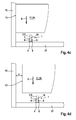
- FIGS. 4a, b show a fastening of the sanitary object 16, of which FIG. 3 Fragments of side walls 11 shows, on the wall 15.
- Standing on a floor 17 sanitary object 16 is pushed to the wall 15 and thereby placed on the two fasteners 1 or postponed.
- FIG. 4a are the two fasteners 1 as in FIG. 3 attached to the wall 15.
- FIG. 4b the two fasteners 1 are fixed with Winkelbefestigern 18 on the floor 17.
- the fasteners 1 can be fastened by a distance from the wall 15.
- FIG. 6 shows one of the fasteners 1 with an angle fastener 18.
- the angle fastener 18 is a ribbed block, which has the shape of a right triangle in side view.
- the angle fastener 18 has a foot plate 19 with a slot 20 for its attachment to the floor 17.
- the angle fastener 18 has a bearing plate 21 for the base plate 5 of the fastener 1.
- the angle fastener 18 has groove-shaped claws 22, in which the base plate 5 of the fastener 1 is laterally inserted.
- the angle fastener 18 allows for an angular attachment of the fastener 1, for example on the floor 17, so that the fastener 1 does not project perpendicularly from the floor 17, but runs parallel to the floor 17, as in FIG. 4b you can see.
- the sanitary object 16 can also put on top of the fastener 1.
- the fasteners 1 are fixed upright on the floor 17 and the sanitary object 16 is placed as mentioned from above.
- the sanitary object 16 is thereby fixed to the floor 17.
- An attachment of the sanitary object 16 with a distance d from the wall 15 is possible, such as FIG. 4d shows.
- Figure 4c shows a fitting with the back 13 on the wall 15 attachment of the sanitary object 16 on the floor 17.
- the attachment of the sanitary object 16 with the two fasteners 1, which are secured with the Winkelbefestigern 18 on the floor 17, as it FIG. 4b shows allows attachment of the sanitary object 16 at a distance from the wall 15 or with the back 13 adjacent to the wall 15.
- the invention provides two adapters 23 which FIG. 5 shows.
- the adapter 23 has a plate 24 with an undercut 25 having block 26 corresponding to the block 12 with the undercut 14 on the inner sides of the inner walls 11 of the sanitary object 16.
- the plate 24 of the adapter 23 has a slot 27, with which the adapter 23 on the inside of the side wall 11 can be screwed.
- the plate 24 of the adapter 23 is angled so that it engages behind the back 13 of the side walls 11 of the sanitary object 16. Without the angling, the adapter 23 can be displaced not only in height, but also in the longitudinal direction on the sanitary object 16 and thereby adapt to the arrangement of the fasteners 1.
Landscapes
- Health & Medical Sciences (AREA)
- Public Health (AREA)
- Life Sciences & Earth Sciences (AREA)
- Engineering & Computer Science (AREA)
- Hydrology & Water Resources (AREA)
- Water Supply & Treatment (AREA)
- Epidemiology (AREA)
- General Health & Medical Sciences (AREA)
- Toilet Supplies (AREA)
- Connection Of Plates (AREA)
- Supports Or Holders For Household Use (AREA)
- Clamps And Clips (AREA)
Abstract
Description
- Die Erfindung betrifft ein bodenstehendes Sanitärobjekt mit zwei Befestigern zur Befestigung des Sanitärobjekts auf einem Boden oder an einer Wand. Auch bei einer Befestigung an einer Wand steht das Sanitärobjekt auf einem an die Wand angrenzenden Boden. Das Sanitärobjekt ist insbesondere eine bodenstehende Toilette oder ein bodenstehendes Bidet.
- Aus ästhetischen Gründen wird zunehmend gefordert, Befestigungen von Sanitärobjekten unsichtbar im Sanitärobjekt anzuordnen.
- Aufgabe der Erfindung ist, ein bodenstehendes Sanitärobjekt mit zwei Befestigern vorzuschlagen, die eine einfache Befestigung des Sanitärobjekts ermöglichen und an Sanitärobjekte unterschiedlicher Form und Abmessungen anpassbar sind.
- Diese Aufgabe wird erfindungsgemäß durch die Merkmale des Anspruchs 1 gelöst. Das erfindungsgemäße, bodenstehende Sanitärobjekt, insbesondere eine Toilette oder ein Bidet, weist zwei Hinterschneidungen auf, die einander entgegengesetzt orientiert vorzugsweise im Sanitärobjekt angeordnet sind. Die Hinterschneidungen können auch von einem Loch bzw. einem Lochrand gebildet sein. "Einander entgegengesetzt orientiert" bedeutet, dass die beiden Hinterschneidungen einander zu- oder abgewandt sind, so dass Befestiger von verschiedenen Seiten an den Hinterschneidungen angreifen können. Vorzugsweise sind die Hinterschneidungen an Innenseiten von Seitenwänden des Sanitärobjekts, insbesondere nahe einer Unterseite oder einer Rückseite, angeordnet. Mit der Unterseite steht das Sanitärobjekt auf einem Boden auf, wenn es in vorgesehener Weise befestigt ist. Die Rückseite des Sanitärobjekts ist einer Wand zugewandt, wobei ein Abstand zwischen der Rückseite des Sanitärobjekts und der Wand bestehen oder das Sanitärobjekt mit seiner Rückseite an der Wand anliegen kann, wenn das Sanitärobjekt in vorgesehener Weise befestigt ist.
- Des Weiteren weist das erfindungsgemäße Sanitärobjekt zwei Befestiger mit je einem Grundteil auf, das zur Befestigung der Befestiger auf dem Boden oder an der Wand befestigbar ist, auf dem oder an der das Sanitärobjekt befestigt werden soll. Die Grundteile der beiden Befestiger können beispielsweise mit Schrauben und mit Hilfe von Dübeln auf dem Boden oder an der Wand befestigt werden, wobei auch andere Befestigungen, beispielsweise durch Kleben, möglich sind.
- Des Weiteren weisen die beiden Befestiger des erfindungsgemäßen Sanitärobjekts Hintergreifelemente auf, die hier als Schnapper bezeichnet werden. Bei einem Aufsetzen des Sanitärobjekts an einer vorgesehenen Stelle in einer Einschnapprichtung, insbesondere von oben auf den Boden oder durch Verschieben des Sanitärobjekts auf dem Boden zur Wand, schnappen die Schnapper der beiden Befestiger an den beiden Hinterschneidungen des Sanitärobjekts ein und hintergreifen die Hinterschneidungen des Sanitärobjekts. Die beiden Befestiger halten dadurch das Sanitärobjekt auf dem Boden oder an der Wand. Die Einschnapprichtung ist die Richtung, in die das Sanitärobjekt zum Einschnappen bewegt werden muss, wobei die Bewegung insbesondere eine reine Translationsbewegung ist. Die Befestiger und das Sanitärobjekt können auch so gestaltet sein, dass es neben der vorgesehenen Einschnapprichtung auch möglich ist, das Sanitärobjekt etwas schräg aufzusetzen oder aufzuschieben. Es besteht also bezüglich der Fügebewegung eine Richtungstoleranz.
- Des Weiteren weisen die beiden Befestiger des erfindungsgemäßen Sanitärobjekts Federelemente auf, die die Schnapper in Hintergriff an den Hinterschneidungen des Sanitärobjekts beaufschlagen. Die Federelemente ermöglichen ein Rückfedern bzw. Ausweichen der Schnapper beim Aufsetzen des Sanitärobjekts, bis die Schnapper durch Federn der Federelemente in Hintergriff an den Hinterschneidungen des Sanitärobjekts gelangen, d.h. bis die Schnapper der beiden Befestiger federnd an den Hinterschneidungen des Sanitärobjekts einschnappen.
- Die beiden Befestiger sind insbesondere identisch oder spiegelsymmetrisch ausgebildet.
- Die Erfindung ermöglicht ein Befestigen eines bodenstehenden Sanitärobjekts mit zwei im Sanitärobjekt angeordneten und damit nicht sichtbaren Befestigern. Die Befestigung erfolgt nach Befestigung der beiden Befestiger auf einem Boden oder an einer Wand einfach durch Aufsetzen des Sanitärobjekts von oben durch Schieben des Sanitärobjekts auf dem Boden zur Wand, wobei das Sanitärobjekt an der Wand anliegend oder mit Abstand zur Wand befestigbar ist. Die beiden Befestiger lassen sich in einem an eine Breite des Sanitärobjekts bzw. einen Abstand der beiden Hinterschneidungen des Sanitärobjekts angepassten Abstand voneinander auf dem Boden oder an der Wand befestigen, wodurch eine Anpassung an das Sanitärobjekt möglich ist bzw. die beiden Befestiger mit verschiedenen Sanitärobjekten verwendbar sind. Bei einer Befestigung der beiden Befestiger an der Wand ist auch eine Anpassung an eine Höhe der Hinterschneidungen des Sanitärobjekts möglich.
- Eine bevorzugte Ausgestaltung der Erfindung sieht vor, dass die Befestiger Anlagen für das Sanitärobjekt aufweisen, die starr mit den Grundteilen der Befestiger sind. Die Anlagen können einstückige Bestandteile der Grundteile sein. Die Anlagen stehen insbesondere im Wesentlichen senkrecht zur Einschnapprichtung, begrenzen also eine Bewegung quer zur Einschnapprichtung. Die Anlagen der beiden Befestiger ermöglichen ein spielfreies Positionieren des Sanitärobjekts insbesondere in seitlicher Richtung, wenn sich die Hinterschneidungen an Innenseiten von Seitenwänden des Sanitärobjekts befinden und das Sanitärobjekt mit den Innenseiten seiner Seitenwände an den Anlagen der beiden Befestiger anliegt, wenn das Sanitärobjekt in vorgesehener Weise befestigt ist. Diese Ausgestaltung der Erfindung vermeidet eine Beweglichkeit des Sanitärobjekts, beispielsweise in seitlicher Richtung, wenn das Sanitärobjekt mit den beiden Befestigern befestigt ist. Auch wird die Aufnahme von quer zur Einschnapprichtung wirkenden Kräften verbessert.
- Eine Ausgestaltung der Erfindung sieht eine Blattfeder als Federelement vor, die den Vorteil einer definierten Federrichtung aufweist. Außer aus Metall kann die Blattfeder auch aus Kunststoff bestehen, es ist eine einstückige Ausführung der Befestiger aus beispielsweise Kunststoff oder Metall möglich. Bevorzugt sind allerdings Verbundausführungen, beispielsweise mit den Grundteilen und den Schnappern aus Kunststoff und Federelementen aus Metall. Vorzugsweise ist die Blattfeder zwischen Grundteil und Schnapper angeordnet, so dass die Blattfeder mit dem Schnapper einen federnden Kragarm bildet. Der Kragarm weicht in einer Federrichtung insbesondere im Wesentlichen senkrecht zur Einschnapprichtung aus, wenn das Sanitärobjekt aufgesetzt oder aufgeschoben wird.
- Eine Ausgestaltung der Erfindung sieht eine Hintergrifffläche der Schnapper spitzwinklig zu einer Federrichtung der Federelemente, also zu einer Bewegungsrichtung der Schnapper beim Federn, vor. Die Hintergriffflächen sind die Flächen der Schnapper, die die Hinterschneidungen des Sanitärobjekts hintergreifen. Die Hintergriffflächen können eben sein und damit einen konstanten Winkel zur Federrichtung aufweisen, oder sie können beispielsweise gekrümmt sein, so dass sich ihr Winkel zur Federrichtung im Verlauf der Hintergriffflächen ändert. Mit einem "spitzen Winkel" ist ein Winkel von weniger als 90 Grad, insbesondere von weniger als 40 Grad, gemeint. Durch die spitzwinklige Ausrichtung der Hintergriffflächen zur Federrichtung ist ein guter Halt des Sanitärobjekts gewährleistet. Die Hintergriffflächen können so spitzwinklig ausgerichtet sein, dass sich das Sanitärobjekt nicht durch Zug lösen lässt, zum Lösen des Sanitärobjekts müssen in diesem Fall die Schnapper in anderer Weise gegen die Federkraft der Federelemente außer Eingriff von den Hinterschneidungen des Sanitärobjekts gebracht werden. Vorzugsweise sind die Hintergriffflächen so spitzwinklig angeordnet, dass sie zwar das Sanitärobjekt an den Hinterschneidungen gegen unbeabsichtigtes Lösen beispielsweise bei einem Stoßen gegen das Sanitärobjekt halten, sich das Sanitärobjekt allerdings durch eine ausreichende Zugkraft lösen lässt. Die zur Federrichtung der Federelemente spitzwinklige Ausrichtung der Hintergriffflächen der Schnapper hat auch den Vorteil, dass die Schnapper Toleranzen ausgleichen und beim Einschnappen so weit federn, bis die Hintergriffflächen an den Hinterschneidungen des Sanitärobjekts anliegen.
- Eine Ausgestaltung der Erfindung sieht vor, dass die Schnapper Abdrückflächen aufweisen, gegen die die Hinterschneidungen des Sanitärobjekts stoßen, wenn das Sanitärobjekt aufgesetzt wird. Die Hinterschneidungen drücken die Schnapper gegen die Federkraft der Federelemente an den Abdrückflächen zur Seite, so dass die Hinterschneidungen des Sanitärobjekts an den Schnappern der Befestiger vorbeitreten und die Schnapper durch die Federelemente federnd hinter den Hinterschneidungen einschnappen, d.h. in Hintergriff an den Hinterschneidungen gelangen, wenn die Hinterschneidungen beim Aufsetzen des Sanitärobjekts die Schnapper überwunden haben. Die Abdrückflächen verlaufen vorzugsweise in einem stumpferen Winkel als Hintergriffflächen zu einer Federrichtung der Federelemente, wobei die Abdrückflächen eben oder gekrümmt sein können, wobei sich in letzterem Fall der Winkel der Abdrückflächen zur Federrichtung der Federelemente über die Abdrückfläche ändert. Durch den stumpferen Winkel der Abdrückflächen zur Federrichtung der Federelemente der Befestiger lässt sich das Sanitärobjekt leicht aufsetzen und die Schnapper schnappen leichtgängig an den Hinterschneidungen ein.
- Eine Ausgestaltung der Erfindung sieht Winkelbefestiger vor, mit denen die Befestiger in einem Winkel auf dem Boden oder an der Wand befestigbar sind. Diese Ausgestaltung der Erfindung ermöglicht eine Änderung einer Ausrichtung der Befestiger.
- Eine Ausgestaltung der Erfindung sieht einen Adapter vor, der an dem Sanitärobjekt festlegbar ist und der eine bzw. die Hinterschneidung aufweist. Diese Ausgestaltung der Erfindung ermöglicht, ein Sanitärobjekt, das keine (geeignete) Hinterschneidung für die Befestiger aufweist, mit einer solchen Hinterschneidung zu versehen oder eine Anbringung der Hinterschneidungen an geeigneter Stelle des Sanitärobjekts, wenn das Sanitärobjekt dort keine eigene Hinterschneidung aufweist.
- Die Erfindung wird nachfolgend anhand eines in der Zeichnung dargestellten Ausführungsbeispiels näher erläutert. Es zeigen:
- Figur 1
- einen Befestiger für ein bodenstehendes Sanitärobjekt gemäß der Erfindung in perspektivischer Darstellung;
- Figur 2
- eine Seitenansicht des Befestigers aus
Figur 1 ; - Figur 3
- einen Ausbruch eines erfindungsgemäßen bodenstehenden Sanitärobjekts mit zwei Befestigern in Draufsicht;
- Figuren 4a-d
- Befestigungen eines bodenstehenden Sanitärobjekts mit zwei Befestigern gemäß der Erfindung in Seitenansicht;
- Figur 5
- das bodenstehende Sanitärobjekt aus
Figur 4a mit Adaptern gemäß der Erfindung in perspektivischer Darstellung; und - Figur 6
- einen Befestiger des bodenstehenden Sanitärobjekts aus
Figur 4b mit einem Winkelbefestiger gemäß der Erfindung. -
Figuren 1 und 2 zeigen einen Befestiger 1 für ein bodenstehendes Sanitärobjekt, das zu seiner Befestigung gemäß der Erfindung zwei Befestiger 1 aufweist. Im Ausführungsbeispiel ist das Sanitärobjekt eine Toilette, eine andere Möglichkeit ist ein Bidet. - Der Befestiger 1 weist eine Blattfeder aus Stahl als Federelement 2 auf, deren eines Ende mit einem Schnapper 3 aus Kunststoff und deren anderes Ende mit einem Grundteil 4, ebenfalls aus Kunststoff, umspritzt ist.
- Das Grundteil 4 ist ein verripptes Teil, das eine ebene Grundplatte 5 mit einem in der Zeichnung nicht sichtbaren Loch zum Durchstecken einer nicht gezeichneten Schraube zur Befestigung des Grundteils 4 und des Befestigers 1 aufweist. Seitenrippen 6 und eine Querrippe 7, die die Seitenrippen 6 verbindet und in der das andere Ende des Federelements 2 starr aufgenommen ist, weisen Ränder in einer zur Grundplatte 5 senkrechten Ebene auf, die eine Anlage 8 des Grundteils 4 für das Sanitärobjekt bilden. Die das Federelement 2 bildende Blattfeder verläuft in einem spitzen Winkel zur Anlage 8 und damit nahezu senkrecht zur Bodenplatte 5 des Grundteils 4.
- Der Schnapper 3 weist in Seitenansicht die Form eines Keils mit einer langen, konvex gekrümmten und hier als Abdrückfläche 9 bezeichneten Fläche auf, die in einem spitzen Winkel zu der das Federelement 2 bildenden Blattfeder verläuft. Aufgrund der Krümmung ändert sich der Winkel, in dem die Abdrückfläche 9 zum Federelement 2 verläuft, über eine Länge der Abdrückfläche 9. An einem dem Grundteil 4 zugewandten Rand der Abdrückfläche 9 weist der Schnapper 3 eine Hintergrifffläche 10 auf, die in einem stumpferen Winkel als die Abdrückfläche 9 zu der das Federelement 2 bildenden Blattfeder verläuft.
- Für die Darstellung der Erfindung ist als bodenstehendes Sanitärobjekt eine bodenstehende Toilette gewählt worden, es ist allerdings wie erwähnt auch ein anderes bodenstehendes Sanitärobjekt möglich, beispielsweise ein bodenstehendes Bidet. In
Figur 3 sind Bruchstücke zweier Seitenwände 11 des Sanitärobjekts zu sehen, die an ihren Innenseiten Blöcke 12 aufweisen, deren eine Rückseite 13 des Sanitärobjekts abgewandten Seiten Hinterschneidungen 14 bilden. Als Rückseite 13 des Sanitärobjekts wird die Seite bezeichnet, die einer Wand 15 zugewandt ist, wenn das Sanitärobjekt in vorgesehener Weise aufgestellt ist. Die beiden Blöcke 12 mit den Hinterschneidungen 14 sind einander zugewandt, was allgemein auch als entgegengesetzt orientiert aufgefasst werden kann. - Das Sanitärobjekt weist zwei gleiche Befestiger 1, wie einer in
Figuren 1 und 2 gezeigt ist, zu seiner Befestigung auf. Zur Befestigung des Sanitärobjekts an der Wand 15 werden die Grundteile 4 der Befestiger 1 an der Wand 15 befestigt, so dass die Grundplatten 5 an der Wand 15 anliegen. Die Befestigung erfolgt beispielsweise mit in der Zeichnung nicht sichtbaren Schrauben, die durch die Löcher in den Grundplatten 5 der Grundteile 4 der Befestiger 1 gesteckt und beispielsweise mit Dübeln in der Wand 15 verankert sind. Die Seitenrippen 6 der Grundteile 4 verdecken die Schrauben, weswegen die Schrauben in der Zeichnung nicht zu sehen sind. Andere Befestigungen sind möglich, beispielsweise können die Befestiger 1 auf in der Wand 15 verankerte und aus der Wand 15 vorstehende Gewindebolzen aufgesetzt und mit aufgeschraubten Muttern befestigt werden. Eine weitere Befestigungsmöglichkeit ist Kleben. - Die Anlagen 8 der Grundteile 4 der Befestiger 1 sind parallel angeordnet, einander abgewandt und die Befestiger 1 werden mit einem solchen Abstand voneinander an der Wand 15 befestigt, dass ein Abstand der Anlagen 8 der Befestiger 1 einem Innenabstand der Seitenwände 11 des Sanitärobjekts an dessen Rückseite 13 entspricht. Zur Befestigung wird das auf einem Boden stehende Sanitärobjekt mit seiner Rückseite 13 an die Wand 15 in Einschnapprichtung E geschoben. Dabei bewegen sich die Seitenwände 11 des Sanitärobjekts an einander abgewandten Seiten der Schnapper 3 der Befestiger 1, also an den Hintergriffflächen 10 der Schnapper 3 vorbei an die Anlagen 8 der Grundteile 4 der Befestiger 1. Die Anlagen 8 der Grundteile 4 der Befestiger 1 positionieren das Sanitärobjekt an seiner Rückseite 13 in seitlicher Richtung an der Wand 15. Sie verhindern eine Verschiebung quer zur Einschnapprichtung E.
- Beim Verschieben des Sanitärobjekts zur Wand 15 stoßen die Blöcke 12 an den Innenseiten 11 des Sanitärobjekts gegen die Abdrückflächen 9 der Schnapper 3 und drücken die Schnapper 3 der Befestiger 1 gegen eine Federkraft der Federelemente 2 zur Seite, so dass die Blöcke 12 an den Schnappern 3 vorbeitreten können. Wenn die Blöcke 12 die Schnapper 3 überwunden haben, federn die Schnapper 3 nach außen, so dass die Hintergriffflächen 10 der Schnapper 3 gegen die Blöcke 12 stoßen und die Blöcke 12 an den Hinterschneidungen 14 hintergreifen. Dadurch ist das Sanitärobjekt an der Wand 15 befestigt. Die Schnapper 3 federn so weit nach außen, bis ihre Hintergriffflächen 10 an den Blöcken 12 anliegen. Der schräge Verlauf der Hintergriffflächen 10 bewirkt einen Toleranzausgleich eines Abstands der Blöcke 12 von der Wand 15.
- Das Schieben des Sanitärobjekts zur Wand 15, bei dem sich die Seitenwände 11 des Sanitärobjekts mit den Blöcken 12 an den Innenseiten an den einander abgewandten Seiten der Schnapper 3 und den Anlagen 8 der Grundteile 4 der beiden Befestiger 1 entlang bewegen, kann auch als Aufsetzen des Sanitärobjekts auf die beiden Befestiger 1 aufgefasst werden. Die Hintergriffflächen 10 der Schnapper 3 verlaufen spitzwinklig zur Federrichtung F der Federelemente 2. Dadurch ist ein guter Halt des Sanitärobjekts an der Wand 15 gewährleistet. Die Hintergriffflächen 10 verlaufen spitzwinkliger zur Federrichtung F der Federelemente 2 als die Abdrückflächen 9, so dass sich das Sanitärobjekt leichter auf die Befestiger 1 aufsetzen und zur Wand 15 schieben, als es sich von der Wand 15 entfernen lässt. Ein unbeabsichtigtes Lösen des Sanitärobjekts von der Wand 15 beispielsweise durch unbeabsichtigtes seitliches Stoßen gegen das Sanitärobjekt wird dadurch vermieden. Gleichzeitig können quer zur Einschnapprichtung E auftretende Kräfte zusätzlich von den Anlagen 8 auf das Grundteil 4 übertragen werden. Zum Lösen von der Wand 15 muss das Sanitärobjekt mit einer großen Kraft von der Wand 15 gezogen werden. Die Kraft zum Lösen des Sanitärobjekts von der Wand 15 ist ein Mehrfaches größer als die Kraft zum Schieben zur Wand 15 zum Aufsetzen des Sanitärobjekts auf die Befestiger 1 und zum Einschnappen der Schnapper 3 an den Hinterschneidungen 14 des Sanitärobjekts. Das Sanitärobjekt kann auch durch Hebeln von der Wand 15 gelöst werden, indem das Sanitärobjekt an einer der Wand 15 und der Rückseite 13 fernen Stelle zur Seite gedrückt wird.
- Die
Figuren 4a, b zeigen ein Befestigen des Sanitärobjekts 16, von demFigur 3 Bruchstücke von Seitenwänden 11 zeigt, an der Wand 15. Das auf einem Boden 17 stehende Sanitärobjekt 16 wird zur Wand 15 geschoben und dabei auf die beiden Befestiger 1 aufgesetzt bzw. aufgeschoben. InFigur 4a sind die beiden Befestiger 1 wie inFigur 3 an der Wand 15 befestigt. InFigur 4b sind die beiden Befestiger 1 mit Winkelbefestigern 18 auf dem Boden 17 befestigt. Die Befestiger 1 lassen sich dadurch mit Abstand von der Wand 15 befestigen. -
Figur 6 zeigt einen der Befestiger 1 mit einem Winkelbefestiger 18. Der Winkelbefestiger 18 ist ein verrippter Bock, der in Seitenansicht die Form eines rechtwinkligen Dreiecks aufweist. Der Winkelbefestiger 18 weist eine Fußplatte 19 mit einem Langloch 20 zu seiner Befestigung auf dem Boden 17 auf. Rechtwinklig zur Fußplatte 19 weist der Winkelbefestiger 18 eine Anlageplatte 21 für die Grundplatte 5 des Befestigers 1 auf. An Rändern der Anlageplatte 21 weist der Winkelbefestiger 18 nutförmige Krallen 22 auf, in die die Grundplatte 5 des Befestigers 1 seitlich einschiebbar ist. Der Winkelbefestiger 18 ermöglicht eine Winkelbefestigung des Befestigers 1 beispielsweise auf dem Boden 17, so dass der Befestiger 1 nicht senkrecht vom Boden 17 absteht, sondern parallel zum Boden 17 verläuft, wie es inFigur 4b zu sehen ist. - Wie die
Figuren 4c, d zeigen, lässt sich das Sanitärobjekt 16 auch von oben auf die Befestiger 1 aufsetzen. Dazu werden die Befestiger 1 nach oben stehend auf dem Boden 17 befestigt und das Sanitärobjekt 16 wird wie erwähnt von oben aufgesetzt. Das Sanitärobjekt 16 ist dadurch auf dem Boden 17 befestigt. Eine Befestigung des Sanitärobjekts 16 mit einem Abstand d von der Wand 15 ist möglich, wieFigur 4d zeigt.Figur 4c zeigt eine mit der Rückseite 13 an der Wand 15 anliegende Befestigung des Sanitärobjekts 16 auf dem Boden 17. Auch die Befestigung des Sanitärobjekts 16 mit den beiden Befestigern 1, die mit den Winkelbefestigern 18 auf dem Boden 17 befestigt sind, wie esFigur 4b zeigt, ermöglicht eine Befestigung des Sanitärobjekts 16 mit Abstand von der Wand 15 oder mit der Rückseite 13 an der Wand 15 anliegend. - Für ein Sanitärobjekt 16, das keine Hinterschneidung für den Hintergriff der Schnapper 3 der Befestiger 1 aufweist oder jedenfalls nicht an geeigneter Stelle, sieht die Erfindung zwei Adapter 23 vor, die
Figur 5 zeigt. Der Adapter 23 weist eine Platte 24 mit einem eine Hinterschneidung 25 aufweisenden Klotz 26 entsprechend dem Block 12 mit der Hinterschneidung 14 an den Innenseiten der Innenwände 11 des Sanitärobjekts 16 auf. Zur Befestigung an der Innenseite der Innenwände 11 des Sanitärobjekts 16 weist die Platte 24 des Adapters 23 ein Langloch 27 auf, mit dem der Adapter 23 an der Innenseite der Seitenwand 11 anschraubbar ist. Andere Befestigungsmöglichkeiten sind möglich. In der dargestellten Ausführungsform ist die Platte 24 des Adapters 23 abgewinkelt, so dass sie die Rückseite 13 der Seitenwände 11 des Sanitärobjekts 16 hintergreift. Ohne die Abwinklung lässt sich der Adapter 23 nicht nur in der Höhe, sondern auch in Längsrichtung am Sanitärobjekt 16 versetzen und dadurch an die Anordnung der Befestiger 1 anpassen. -
- 1
- Befestiger
- 2
- Federelement
- 3
- Schnapper
- 4
- Grundteil
- 5
- Grundplatte
- 6
- Seitenrippe
- 7
- Querrippe
- 8
- Anlage
- 9
- Abdrückfläche
- 10
- Hintergrifffläche
- 11
- Seitenwand eines Sanitärobjekts
- 12
- Block
- 13
- Rückseite einer Seitenwand 11 eines Sanitärobjekts
- 14
- Hinterschneidung
- 15
- Wand
- 16
- Sanitärobjekt
- 17
- Boden
- 18
- Winkelbefestiger
- 19
- Fußplatte
- 20
- Langloch
- 21
- Anlageplatte
- 22
- Kralle
- 23
- Adapter
- 24
- Platte
- 25
- Hinterschneidung
- 26
- Klotz
- 27
- Langloch
- d
- Abstand eines Sanitärobjekts 16 von einer Wand 15
- E
- Einschnapprichtung
- F
- Federrichtung
Claims (7)
- Bodenstehendes Sanitärobjekt mit zwei Hinterschneidungen (14) und mit zwei Befestigern (1) zur Befestigung des Sanitärobjekts (16) auf einem Boden (17) oder an einer Wand (15), wobei die Befestiger (1) ein Grundteil (4), das zur Befestigung auf dem Boden (17) oder an der Wand (15) ausgebildet und vorgesehen ist, einen Schnapper (3), der zum Einschnappen an und zum Hintergeifen der Hinterschneidungen (14) des Sanitärobjekts (16) ausgebildet und vorgesehen ist, und ein Federelement (2), das die Schnapper (3) in den Hintergriff an den Hinterschneidungen (14) des Sanitärobjekts (16) beaufschlagt, aufweisen.
- Sanitärobjekt nach Anspruch 1, dadurch gekennzeichnet, dass jeder Befestiger (1) eine Anlage (8) für das Sanitärobjekt (16) aufweist, die starr mit dem Grundteil (4) ist, wobei die Anlagen (8) insbesondere im Wesentlichen senkrecht zu einer Einschnapprichtung (E) und einander abgewandt stehen, und wobei das Sanitärobjekt (16) derart an den Anlagen (8) anliegt, dass eine Verschiebung quer zur Einschnapprichtung (E) verhindert wird.
- Sanitärobjekt nach Anspruch 1 oder 2, dadurch gekennzeichnet, dass das Federelement (2) eine Blattfeder ist.
- Sanitärobjekt nach einem der Ansprüche 1-3, dadurch gekennzeichnet, dass der Schnapper (3) eine Abdrückfläche (9) aufweist, an der das Sanitärobjekt (1) den Schnapper (3) gegen eine Federkraft des Federelements (2) zur Seite drückt, bis der Schnapper (3) an der Hinterschneidung (14) einschnappt und sie hintergreift, wenn das Sanitärobjekt (16) auf den Befestiger (1) aufgesetzt wird.
- Sanitärobjekt nach einem der vorhergehenden Ansprüche, dadurch gekennzeichnet, dass eine Hintergrifffläche (10) des Schnappers (3) in einem spitzeren Winkel zu einer Federrichtung des Federelements (2) verläuft als eine Abdrückfläche (9) des Schnappers (3).
- Sanitärobjekt nach einem der vorhergehenden Ansprüche, dadurch gekennzeichnet, dass der Befestiger (1) einen Winkelbefestiger (18) zu einer Winkelbefestigung des Befestigers (1) aufweist.
- Sanitärobjekt nach einem der vorhergehenden Ansprüche, dadurch gekennzeichnet, dass das Sanitärobjekt (16) einen Adapter (23) aufweist, der an dem Sanitärobjekt (16) festlegbar ist und der eine Hinterschneidung (25) aufweist.
Priority Applications (1)
| Application Number | Priority Date | Filing Date | Title |
|---|---|---|---|
| PL15401098T PL3006635T3 (pl) | 2014-10-09 | 2015-10-02 | Stojący na podłodze obiekt przedmiot sanitarny z dwoma łącznikami |
Applications Claiming Priority (2)
| Application Number | Priority Date | Filing Date | Title |
|---|---|---|---|
| DE102014014756 | 2014-10-09 | ||
| DE102015112456.4A DE102015112456A1 (de) | 2014-10-09 | 2015-07-30 | Bodenstehendes Sanitärobjekt mit zwei Befestigern |
Publications (2)
| Publication Number | Publication Date |
|---|---|
| EP3006635A1 true EP3006635A1 (de) | 2016-04-13 |
| EP3006635B1 EP3006635B1 (de) | 2019-11-27 |
Family
ID=54360415
Family Applications (1)
| Application Number | Title | Priority Date | Filing Date |
|---|---|---|---|
| EP15401098.7A Active EP3006635B1 (de) | 2014-10-09 | 2015-10-02 | Bodenstehendes sanitärobjekt mit zwei befestigern |
Country Status (5)
| Country | Link |
|---|---|
| EP (1) | EP3006635B1 (de) |
| CN (1) | CN105507406B (de) |
| DE (1) | DE102015112456A1 (de) |
| ES (1) | ES2760260T3 (de) |
| PL (1) | PL3006635T3 (de) |
Cited By (6)
| Publication number | Priority date | Publication date | Assignee | Title |
|---|---|---|---|---|
| EP3296474A1 (de) * | 2016-09-20 | 2018-03-21 | fischerwerke GmbH & Co. KG | Befestigungseinrichtung für ein wandhängendes sanitärobjekt, befestigungsanordnung und verfahren zur montage eines wandhängenden sanitärobjekts |
| EP3296473A1 (de) * | 2016-09-20 | 2018-03-21 | fischerwerke GmbH & Co. KG | Befestigungseinrichtung für ein wandhängendes sanitärobjekt, befestigungsanordnung und verfahren zur demontage eines wandhängenden sanitärobjekts |
| EP3388589A1 (de) * | 2017-04-10 | 2018-10-17 | fischerwerke GmbH & Co. KG | Befestigungsvorrichtung und befestigungsanordnung |
| WO2020058276A1 (en) | 2018-09-20 | 2020-03-26 | Sanitea S.R.L. | Kit for mounting floor-standing sanitary fixtures, system comprising said kit and related method |
| EP4060136A1 (de) | 2021-03-16 | 2022-09-21 | Sanitea S.R.L. | Bausatz zur befestigung von sanitärarmaturen, system mit diesem bausatz und montageverfahren |
| EP4786695A1 (de) | 2025-02-03 | 2026-08-05 | Sanitea S.R.L. | Kit zur befestigung von sanitärartikeln, system mit diesem kit und montageverfahren |
Citations (3)
| Publication number | Priority date | Publication date | Assignee | Title |
|---|---|---|---|---|
| CH443169A (de) * | 1965-08-13 | 1967-08-31 | Kera Werke Ag | Sanitärer Apparat mit Befestigungseinrichtung |
| DE2117777A1 (de) * | 1971-04-13 | 1972-10-19 | Müller, Hans, 7000 Stuttgart | Vorrichtung zum Befestigen eines Beckens auf dem Fußboden |
| DE202010009280U1 (de) * | 2010-06-18 | 2011-12-22 | Fischer Italia S.R.L. | Befestigungsvorrichtung zur Befestigung eines wandhängenden Sanitärobjekts |
Family Cites Families (4)
| Publication number | Priority date | Publication date | Assignee | Title |
|---|---|---|---|---|
| AT507336B1 (de) * | 2008-09-25 | 2010-07-15 | Neuhofer Franz Jun | Vorrichtung zur befestigung einer abschlussleiste |
| CN201453043U (zh) * | 2009-03-06 | 2010-05-12 | 王剑伟 | 一种淋浴房低盆盆体与裙边的连接结构 |
| CN102434549B (zh) * | 2011-08-30 | 2015-01-28 | 深圳市江波龙电子有限公司 | 卡扣件、基座以及卡扣配合体 |
| CN203404180U (zh) * | 2013-06-26 | 2014-01-22 | 朱成祥 | 一种新型卡接结构 |
-
2015
- 2015-07-30 DE DE102015112456.4A patent/DE102015112456A1/de not_active Withdrawn
- 2015-10-02 EP EP15401098.7A patent/EP3006635B1/de active Active
- 2015-10-02 ES ES15401098T patent/ES2760260T3/es active Active
- 2015-10-02 PL PL15401098T patent/PL3006635T3/pl unknown
- 2015-10-09 CN CN201510647576.1A patent/CN105507406B/zh active Active
Patent Citations (3)
| Publication number | Priority date | Publication date | Assignee | Title |
|---|---|---|---|---|
| CH443169A (de) * | 1965-08-13 | 1967-08-31 | Kera Werke Ag | Sanitärer Apparat mit Befestigungseinrichtung |
| DE2117777A1 (de) * | 1971-04-13 | 1972-10-19 | Müller, Hans, 7000 Stuttgart | Vorrichtung zum Befestigen eines Beckens auf dem Fußboden |
| DE202010009280U1 (de) * | 2010-06-18 | 2011-12-22 | Fischer Italia S.R.L. | Befestigungsvorrichtung zur Befestigung eines wandhängenden Sanitärobjekts |
Cited By (6)
| Publication number | Priority date | Publication date | Assignee | Title |
|---|---|---|---|---|
| EP3296474A1 (de) * | 2016-09-20 | 2018-03-21 | fischerwerke GmbH & Co. KG | Befestigungseinrichtung für ein wandhängendes sanitärobjekt, befestigungsanordnung und verfahren zur montage eines wandhängenden sanitärobjekts |
| EP3296473A1 (de) * | 2016-09-20 | 2018-03-21 | fischerwerke GmbH & Co. KG | Befestigungseinrichtung für ein wandhängendes sanitärobjekt, befestigungsanordnung und verfahren zur demontage eines wandhängenden sanitärobjekts |
| EP3388589A1 (de) * | 2017-04-10 | 2018-10-17 | fischerwerke GmbH & Co. KG | Befestigungsvorrichtung und befestigungsanordnung |
| WO2020058276A1 (en) | 2018-09-20 | 2020-03-26 | Sanitea S.R.L. | Kit for mounting floor-standing sanitary fixtures, system comprising said kit and related method |
| EP4060136A1 (de) | 2021-03-16 | 2022-09-21 | Sanitea S.R.L. | Bausatz zur befestigung von sanitärarmaturen, system mit diesem bausatz und montageverfahren |
| EP4786695A1 (de) | 2025-02-03 | 2026-08-05 | Sanitea S.R.L. | Kit zur befestigung von sanitärartikeln, system mit diesem kit und montageverfahren |
Also Published As
| Publication number | Publication date |
|---|---|
| PL3006635T3 (pl) | 2020-06-01 |
| DE102015112456A1 (de) | 2016-04-14 |
| ES2760260T3 (es) | 2020-05-13 |
| CN105507406B (zh) | 2019-12-27 |
| CN105507406A (zh) | 2016-04-20 |
| EP3006635B1 (de) | 2019-11-27 |
Similar Documents
| Publication | Publication Date | Title |
|---|---|---|
| EP3006635B1 (de) | Bodenstehendes sanitärobjekt mit zwei befestigern | |
| EP1415056B1 (de) | Paneel sowie Befestigungssystem für Paneele | |
| DE102008003744B3 (de) | Abstützung für ein System zum Befestigen einer Schiene und System zum Befestigen einer Schiene | |
| EP1601881B1 (de) | Beschlag mit arretiervorrichtung | |
| DE102010028653A1 (de) | System zum Befestigen eines Anbauteiles an Montagegeschienen | |
| DE102009043993B4 (de) | Hilfsvorrichtung zur Befestigung eines Distanzelementes an einem Bodenbrett | |
| DE69514817T2 (de) | Tragvorrichtung für abgehängte decken | |
| DE202009017769U1 (de) | Vorrichtung zum Festlegen des Randes eines Bodenbelags an einer Profilkonstruktion | |
| DE102009030768A1 (de) | Befestigungseinrichtung zu einer Schraubbefestigung an einer Montageschiene | |
| DE202023104114U1 (de) | Halteklammer sowie Befestigungs- und Installationssystem zur Montage von Montageschienen | |
| EP2295654A1 (de) | Bodenablauf und Verfahren zur Montage eines Bodenablaufs | |
| DE19722778C1 (de) | Verankerungseinheit | |
| DE102014112529A1 (de) | Mechanische Verbindung für Paneele und Verfahren zur Montage einer Verriegelungsfeder in einem Paneel | |
| DE202007003061U1 (de) | Montageverbinder und Montageeinheit | |
| DE202008015077U1 (de) | Adapter zur Befestigung von Solarmodulen, mit Adapter befestigte Solarmodule und Werkzeug zum Lösen der Befestigung | |
| DE102016124988A1 (de) | Beschlag für das Verlegen von Terrassendielen | |
| DE3445880A1 (de) | Schubkasten aus kunststoff | |
| EP2345086A2 (de) | Adapter zur befestigung von solarmodulen, mit adaptern befestigte solarmodule und verfahren zur befestigung von solarmodulen | |
| DE202011106955U1 (de) | Vorrichtung zur Befestigung von, insbesondere solartechnischen, Anlagen | |
| DE29900999U1 (de) | Befestigungselement | |
| EP3146123B1 (de) | Fugenabdeckvorrichtung | |
| DE10326704A1 (de) | Befestigungsmittel für Paneele | |
| DE19744340A1 (de) | Modulares Verkleidungssystem | |
| DE10158614A1 (de) | Rollenbefestigung | |
| DE202010013189U1 (de) | Vorrichtung zum Befestigen einer Profilierleiste |
Legal Events
| Date | Code | Title | Description |
|---|---|---|---|
| PUAI | Public reference made under article 153(3) epc to a published international application that has entered the european phase |
Free format text: ORIGINAL CODE: 0009012 |
|
| AK | Designated contracting states |
Kind code of ref document: A1 Designated state(s): AL AT BE BG CH CY CZ DE DK EE ES FI FR GB GR HR HU IE IS IT LI LT LU LV MC MK MT NL NO PL PT RO RS SE SI SK SM TR |
|
| AX | Request for extension of the european patent |
Extension state: BA ME |
|
| 17P | Request for examination filed |
Effective date: 20160927 |
|
| RBV | Designated contracting states (corrected) |
Designated state(s): AL AT BE BG CH CY CZ DE DK EE ES FI FR GB GR HR HU IE IS IT LI LT LU LV MC MK MT NL NO PL PT RO RS SE SI SK SM TR |
|
| GRAP | Despatch of communication of intention to grant a patent |
Free format text: ORIGINAL CODE: EPIDOSNIGR1 |
|
| STAA | Information on the status of an ep patent application or granted ep patent |
Free format text: STATUS: GRANT OF PATENT IS INTENDED |
|
| GRAJ | Information related to disapproval of communication of intention to grant by the applicant or resumption of examination proceedings by the epo deleted |
Free format text: ORIGINAL CODE: EPIDOSDIGR1 |
|
| STAA | Information on the status of an ep patent application or granted ep patent |
Free format text: STATUS: REQUEST FOR EXAMINATION WAS MADE |
|
| GRAJ | Information related to disapproval of communication of intention to grant by the applicant or resumption of examination proceedings by the epo deleted |
Free format text: ORIGINAL CODE: EPIDOSDIGR1 |
|
| GRAP | Despatch of communication of intention to grant a patent |
Free format text: ORIGINAL CODE: EPIDOSNIGR1 |
|
| INTG | Intention to grant announced |
Effective date: 20190522 |
|
| INTC | Intention to grant announced (deleted) | ||
| GRAP | Despatch of communication of intention to grant a patent |
Free format text: ORIGINAL CODE: EPIDOSNIGR1 |
|
| STAA | Information on the status of an ep patent application or granted ep patent |
Free format text: STATUS: GRANT OF PATENT IS INTENDED |
|
| INTG | Intention to grant announced |
Effective date: 20190612 |
|
| INTC | Intention to grant announced (deleted) | ||
| INTG | Intention to grant announced |
Effective date: 20190709 |
|
| GRAS | Grant fee paid |
Free format text: ORIGINAL CODE: EPIDOSNIGR3 |
|
| GRAA | (expected) grant |
Free format text: ORIGINAL CODE: 0009210 |
|
| STAA | Information on the status of an ep patent application or granted ep patent |
Free format text: STATUS: THE PATENT HAS BEEN GRANTED |
|
| AK | Designated contracting states |
Kind code of ref document: B1 Designated state(s): AL AT BE BG CH CY CZ DE DK EE ES FI FR GB GR HR HU IE IS IT LI LT LU LV MC MK MT NL NO PL PT RO RS SE SI SK SM TR |
|
| REG | Reference to a national code |
Ref country code: GB Ref legal event code: FG4D Free format text: NOT ENGLISH |
|
| REG | Reference to a national code |
Ref country code: CH Ref legal event code: EP |
|
| REG | Reference to a national code |
Ref country code: AT Ref legal event code: REF Ref document number: 1206795 Country of ref document: AT Kind code of ref document: T Effective date: 20191215 |
|
| REG | Reference to a national code |
Ref country code: DE Ref legal event code: R096 Ref document number: 502015011048 Country of ref document: DE |
|
| REG | Reference to a national code |
Ref country code: IE Ref legal event code: FG4D Free format text: LANGUAGE OF EP DOCUMENT: GERMAN |
|
| REG | Reference to a national code |
Ref country code: NL Ref legal event code: FP |
|
| REG | Reference to a national code |
Ref country code: LT Ref legal event code: MG4D |
|
| PG25 | Lapsed in a contracting state [announced via postgrant information from national office to epo] |
Ref country code: GR Free format text: LAPSE BECAUSE OF FAILURE TO SUBMIT A TRANSLATION OF THE DESCRIPTION OR TO PAY THE FEE WITHIN THE PRESCRIBED TIME-LIMIT Effective date: 20200228 Ref country code: NO Free format text: LAPSE BECAUSE OF FAILURE TO SUBMIT A TRANSLATION OF THE DESCRIPTION OR TO PAY THE FEE WITHIN THE PRESCRIBED TIME-LIMIT Effective date: 20200227 Ref country code: SE Free format text: LAPSE BECAUSE OF FAILURE TO SUBMIT A TRANSLATION OF THE DESCRIPTION OR TO PAY THE FEE WITHIN THE PRESCRIBED TIME-LIMIT Effective date: 20191127 Ref country code: LV Free format text: LAPSE BECAUSE OF FAILURE TO SUBMIT A TRANSLATION OF THE DESCRIPTION OR TO PAY THE FEE WITHIN THE PRESCRIBED TIME-LIMIT Effective date: 20191127 Ref country code: BG Free format text: LAPSE BECAUSE OF FAILURE TO SUBMIT A TRANSLATION OF THE DESCRIPTION OR TO PAY THE FEE WITHIN THE PRESCRIBED TIME-LIMIT Effective date: 20200227 Ref country code: FI Free format text: LAPSE BECAUSE OF FAILURE TO SUBMIT A TRANSLATION OF THE DESCRIPTION OR TO PAY THE FEE WITHIN THE PRESCRIBED TIME-LIMIT Effective date: 20191127 Ref country code: LT Free format text: LAPSE BECAUSE OF FAILURE TO SUBMIT A TRANSLATION OF THE DESCRIPTION OR TO PAY THE FEE WITHIN THE PRESCRIBED TIME-LIMIT Effective date: 20191127 |
|
| REG | Reference to a national code |
Ref country code: ES Ref legal event code: FG2A Ref document number: 2760260 Country of ref document: ES Kind code of ref document: T3 Effective date: 20200513 |
|
| PG25 | Lapsed in a contracting state [announced via postgrant information from national office to epo] |
Ref country code: IS Free format text: LAPSE BECAUSE OF FAILURE TO SUBMIT A TRANSLATION OF THE DESCRIPTION OR TO PAY THE FEE WITHIN THE PRESCRIBED TIME-LIMIT Effective date: 20200327 Ref country code: HR Free format text: LAPSE BECAUSE OF FAILURE TO SUBMIT A TRANSLATION OF THE DESCRIPTION OR TO PAY THE FEE WITHIN THE PRESCRIBED TIME-LIMIT Effective date: 20191127 Ref country code: RS Free format text: LAPSE BECAUSE OF FAILURE TO SUBMIT A TRANSLATION OF THE DESCRIPTION OR TO PAY THE FEE WITHIN THE PRESCRIBED TIME-LIMIT Effective date: 20191127 |
|
| PG25 | Lapsed in a contracting state [announced via postgrant information from national office to epo] |
Ref country code: AL Free format text: LAPSE BECAUSE OF FAILURE TO SUBMIT A TRANSLATION OF THE DESCRIPTION OR TO PAY THE FEE WITHIN THE PRESCRIBED TIME-LIMIT Effective date: 20191127 |
|
| PG25 | Lapsed in a contracting state [announced via postgrant information from national office to epo] |
Ref country code: CZ Free format text: LAPSE BECAUSE OF FAILURE TO SUBMIT A TRANSLATION OF THE DESCRIPTION OR TO PAY THE FEE WITHIN THE PRESCRIBED TIME-LIMIT Effective date: 20191127 Ref country code: RO Free format text: LAPSE BECAUSE OF FAILURE TO SUBMIT A TRANSLATION OF THE DESCRIPTION OR TO PAY THE FEE WITHIN THE PRESCRIBED TIME-LIMIT Effective date: 20191127 Ref country code: EE Free format text: LAPSE BECAUSE OF FAILURE TO SUBMIT A TRANSLATION OF THE DESCRIPTION OR TO PAY THE FEE WITHIN THE PRESCRIBED TIME-LIMIT Effective date: 20191127 Ref country code: PT Free format text: LAPSE BECAUSE OF FAILURE TO SUBMIT A TRANSLATION OF THE DESCRIPTION OR TO PAY THE FEE WITHIN THE PRESCRIBED TIME-LIMIT Effective date: 20200419 Ref country code: DK Free format text: LAPSE BECAUSE OF FAILURE TO SUBMIT A TRANSLATION OF THE DESCRIPTION OR TO PAY THE FEE WITHIN THE PRESCRIBED TIME-LIMIT Effective date: 20191127 |
|
| REG | Reference to a national code |
Ref country code: DE Ref legal event code: R097 Ref document number: 502015011048 Country of ref document: DE |
|
| PG25 | Lapsed in a contracting state [announced via postgrant information from national office to epo] |
Ref country code: SM Free format text: LAPSE BECAUSE OF FAILURE TO SUBMIT A TRANSLATION OF THE DESCRIPTION OR TO PAY THE FEE WITHIN THE PRESCRIBED TIME-LIMIT Effective date: 20191127 Ref country code: SK Free format text: LAPSE BECAUSE OF FAILURE TO SUBMIT A TRANSLATION OF THE DESCRIPTION OR TO PAY THE FEE WITHIN THE PRESCRIBED TIME-LIMIT Effective date: 20191127 |
|
| PLBE | No opposition filed within time limit |
Free format text: ORIGINAL CODE: 0009261 |
|
| STAA | Information on the status of an ep patent application or granted ep patent |
Free format text: STATUS: NO OPPOSITION FILED WITHIN TIME LIMIT |
|
| 26N | No opposition filed |
Effective date: 20200828 |
|
| PG25 | Lapsed in a contracting state [announced via postgrant information from national office to epo] |
Ref country code: SI Free format text: LAPSE BECAUSE OF FAILURE TO SUBMIT A TRANSLATION OF THE DESCRIPTION OR TO PAY THE FEE WITHIN THE PRESCRIBED TIME-LIMIT Effective date: 20191127 |
|
| PG25 | Lapsed in a contracting state [announced via postgrant information from national office to epo] |
Ref country code: LU Free format text: LAPSE BECAUSE OF NON-PAYMENT OF DUE FEES Effective date: 20201002 Ref country code: MC Free format text: LAPSE BECAUSE OF FAILURE TO SUBMIT A TRANSLATION OF THE DESCRIPTION OR TO PAY THE FEE WITHIN THE PRESCRIBED TIME-LIMIT Effective date: 20191127 |
|
| REG | Reference to a national code |
Ref country code: BE Ref legal event code: MM Effective date: 20201031 |
|
| PG25 | Lapsed in a contracting state [announced via postgrant information from national office to epo] |
Ref country code: BE Free format text: LAPSE BECAUSE OF NON-PAYMENT OF DUE FEES Effective date: 20201031 |
|
| PG25 | Lapsed in a contracting state [announced via postgrant information from national office to epo] |
Ref country code: IE Free format text: LAPSE BECAUSE OF NON-PAYMENT OF DUE FEES Effective date: 20201002 |
|
| REG | Reference to a national code |
Ref country code: AT Ref legal event code: MM01 Ref document number: 1206795 Country of ref document: AT Kind code of ref document: T Effective date: 20201002 |
|
| PG25 | Lapsed in a contracting state [announced via postgrant information from national office to epo] |
Ref country code: AT Free format text: LAPSE BECAUSE OF NON-PAYMENT OF DUE FEES Effective date: 20201002 |
|
| PG25 | Lapsed in a contracting state [announced via postgrant information from national office to epo] |
Ref country code: MT Free format text: LAPSE BECAUSE OF FAILURE TO SUBMIT A TRANSLATION OF THE DESCRIPTION OR TO PAY THE FEE WITHIN THE PRESCRIBED TIME-LIMIT Effective date: 20191127 Ref country code: CY Free format text: LAPSE BECAUSE OF FAILURE TO SUBMIT A TRANSLATION OF THE DESCRIPTION OR TO PAY THE FEE WITHIN THE PRESCRIBED TIME-LIMIT Effective date: 20191127 |
|
| PG25 | Lapsed in a contracting state [announced via postgrant information from national office to epo] |
Ref country code: MK Free format text: LAPSE BECAUSE OF FAILURE TO SUBMIT A TRANSLATION OF THE DESCRIPTION OR TO PAY THE FEE WITHIN THE PRESCRIBED TIME-LIMIT Effective date: 20191127 |
|
| PGFP | Annual fee paid to national office [announced via postgrant information from national office to epo] |
Ref country code: CH Payment date: 20221024 Year of fee payment: 8 |
|
| PGFP | Annual fee paid to national office [announced via postgrant information from national office to epo] |
Ref country code: NL Payment date: 20231019 Year of fee payment: 9 |
|
| REG | Reference to a national code |
Ref country code: CH Ref legal event code: PL |
|
| PG25 | Lapsed in a contracting state [announced via postgrant information from national office to epo] |
Ref country code: CH Free format text: LAPSE BECAUSE OF NON-PAYMENT OF DUE FEES Effective date: 20231031 |
|
| PG25 | Lapsed in a contracting state [announced via postgrant information from national office to epo] |
Ref country code: CH Free format text: LAPSE BECAUSE OF NON-PAYMENT OF DUE FEES Effective date: 20231031 |
|
| REG | Reference to a national code |
Ref country code: NL Ref legal event code: MM Effective date: 20241101 |
|
| PG25 | Lapsed in a contracting state [announced via postgrant information from national office to epo] |
Ref country code: NL Free format text: LAPSE BECAUSE OF NON-PAYMENT OF DUE FEES Effective date: 20241101 |
|
| PGFP | Annual fee paid to national office [announced via postgrant information from national office to epo] |
Ref country code: PL Payment date: 20250923 Year of fee payment: 11 Ref country code: TR Payment date: 20250923 Year of fee payment: 11 |
|
| PGFP | Annual fee paid to national office [announced via postgrant information from national office to epo] |
Ref country code: DE Payment date: 20250905 Year of fee payment: 11 |
|
| PGFP | Annual fee paid to national office [announced via postgrant information from national office to epo] |
Ref country code: GB Payment date: 20251022 Year of fee payment: 11 |
|
| PGFP | Annual fee paid to national office [announced via postgrant information from national office to epo] |
Ref country code: IT Payment date: 20251024 Year of fee payment: 11 |
|
| PGFP | Annual fee paid to national office [announced via postgrant information from national office to epo] |
Ref country code: FR Payment date: 20251030 Year of fee payment: 11 |
|
| PGFP | Annual fee paid to national office [announced via postgrant information from national office to epo] |
Ref country code: ES Payment date: 20251210 Year of fee payment: 11 |