EP3005360B1 - Compensation d'erreur dans representations decomposées d'un champ sonore - Google Patents
Compensation d'erreur dans representations decomposées d'un champ sonore Download PDFInfo
- Publication number
- EP3005360B1 EP3005360B1 EP14734328.9A EP14734328A EP3005360B1 EP 3005360 B1 EP3005360 B1 EP 3005360B1 EP 14734328 A EP14734328 A EP 14734328A EP 3005360 B1 EP3005360 B1 EP 3005360B1
- Authority
- EP
- European Patent Office
- Prior art keywords
- vectors
- matrix
- spherical harmonic
- harmonic coefficients
- audio
- Prior art date
- Legal status (The legal status is an assumption and is not a legal conclusion. Google has not performed a legal analysis and makes no representation as to the accuracy of the status listed.)
- Active
Links
Images


Classifications
-
- H—ELECTRICITY
- H04—ELECTRIC COMMUNICATION TECHNIQUE
- H04S—STEREOPHONIC SYSTEMS
- H04S5/00—Pseudo-stereo systems, e.g. in which additional channel signals are derived from monophonic signals by means of phase shifting, time delay or reverberation
- H04S5/005—Pseudo-stereo systems, e.g. in which additional channel signals are derived from monophonic signals by means of phase shifting, time delay or reverberation of the pseudo five- or more-channel type, e.g. virtual surround
-
- G—PHYSICS
- G06—COMPUTING; CALCULATING OR COUNTING
- G06F—ELECTRIC DIGITAL DATA PROCESSING
- G06F17/00—Digital computing or data processing equipment or methods, specially adapted for specific functions
- G06F17/10—Complex mathematical operations
- G06F17/16—Matrix or vector computation, e.g. matrix-matrix or matrix-vector multiplication, matrix factorization
-
- G—PHYSICS
- G10—MUSICAL INSTRUMENTS; ACOUSTICS
- G10L—SPEECH ANALYSIS OR SYNTHESIS; SPEECH RECOGNITION; SPEECH OR VOICE PROCESSING; SPEECH OR AUDIO CODING OR DECODING
- G10L19/00—Speech or audio signals analysis-synthesis techniques for redundancy reduction, e.g. in vocoders; Coding or decoding of speech or audio signals, using source filter models or psychoacoustic analysis
- G10L19/002—Dynamic bit allocation
-
- G—PHYSICS
- G10—MUSICAL INSTRUMENTS; ACOUSTICS
- G10L—SPEECH ANALYSIS OR SYNTHESIS; SPEECH RECOGNITION; SPEECH OR VOICE PROCESSING; SPEECH OR AUDIO CODING OR DECODING
- G10L19/00—Speech or audio signals analysis-synthesis techniques for redundancy reduction, e.g. in vocoders; Coding or decoding of speech or audio signals, using source filter models or psychoacoustic analysis
- G10L19/008—Multichannel audio signal coding or decoding using interchannel correlation to reduce redundancy, e.g. joint-stereo, intensity-coding or matrixing
-
- G—PHYSICS
- G10—MUSICAL INSTRUMENTS; ACOUSTICS
- G10L—SPEECH ANALYSIS OR SYNTHESIS; SPEECH RECOGNITION; SPEECH OR VOICE PROCESSING; SPEECH OR AUDIO CODING OR DECODING
- G10L19/00—Speech or audio signals analysis-synthesis techniques for redundancy reduction, e.g. in vocoders; Coding or decoding of speech or audio signals, using source filter models or psychoacoustic analysis
- G10L19/02—Speech or audio signals analysis-synthesis techniques for redundancy reduction, e.g. in vocoders; Coding or decoding of speech or audio signals, using source filter models or psychoacoustic analysis using spectral analysis, e.g. transform vocoders or subband vocoders
- G10L19/0204—Speech or audio signals analysis-synthesis techniques for redundancy reduction, e.g. in vocoders; Coding or decoding of speech or audio signals, using source filter models or psychoacoustic analysis using spectral analysis, e.g. transform vocoders or subband vocoders using subband decomposition
-
- G—PHYSICS
- G10—MUSICAL INSTRUMENTS; ACOUSTICS
- G10L—SPEECH ANALYSIS OR SYNTHESIS; SPEECH RECOGNITION; SPEECH OR VOICE PROCESSING; SPEECH OR AUDIO CODING OR DECODING
- G10L19/00—Speech or audio signals analysis-synthesis techniques for redundancy reduction, e.g. in vocoders; Coding or decoding of speech or audio signals, using source filter models or psychoacoustic analysis
- G10L19/02—Speech or audio signals analysis-synthesis techniques for redundancy reduction, e.g. in vocoders; Coding or decoding of speech or audio signals, using source filter models or psychoacoustic analysis using spectral analysis, e.g. transform vocoders or subband vocoders
- G10L19/032—Quantisation or dequantisation of spectral components
- G10L19/038—Vector quantisation, e.g. TwinVQ audio
-
- G—PHYSICS
- G10—MUSICAL INSTRUMENTS; ACOUSTICS
- G10L—SPEECH ANALYSIS OR SYNTHESIS; SPEECH RECOGNITION; SPEECH OR VOICE PROCESSING; SPEECH OR AUDIO CODING OR DECODING
- G10L19/00—Speech or audio signals analysis-synthesis techniques for redundancy reduction, e.g. in vocoders; Coding or decoding of speech or audio signals, using source filter models or psychoacoustic analysis
- G10L19/04—Speech or audio signals analysis-synthesis techniques for redundancy reduction, e.g. in vocoders; Coding or decoding of speech or audio signals, using source filter models or psychoacoustic analysis using predictive techniques
- G10L19/06—Determination or coding of the spectral characteristics, e.g. of the short-term prediction coefficients
-
- G—PHYSICS
- G10—MUSICAL INSTRUMENTS; ACOUSTICS
- G10L—SPEECH ANALYSIS OR SYNTHESIS; SPEECH RECOGNITION; SPEECH OR VOICE PROCESSING; SPEECH OR AUDIO CODING OR DECODING
- G10L19/00—Speech or audio signals analysis-synthesis techniques for redundancy reduction, e.g. in vocoders; Coding or decoding of speech or audio signals, using source filter models or psychoacoustic analysis
- G10L19/04—Speech or audio signals analysis-synthesis techniques for redundancy reduction, e.g. in vocoders; Coding or decoding of speech or audio signals, using source filter models or psychoacoustic analysis using predictive techniques
- G10L19/16—Vocoder architecture
- G10L19/167—Audio streaming, i.e. formatting and decoding of an encoded audio signal representation into a data stream for transmission or storage purposes
-
- G—PHYSICS
- G10—MUSICAL INSTRUMENTS; ACOUSTICS
- G10L—SPEECH ANALYSIS OR SYNTHESIS; SPEECH RECOGNITION; SPEECH OR VOICE PROCESSING; SPEECH OR AUDIO CODING OR DECODING
- G10L19/00—Speech or audio signals analysis-synthesis techniques for redundancy reduction, e.g. in vocoders; Coding or decoding of speech or audio signals, using source filter models or psychoacoustic analysis
- G10L19/04—Speech or audio signals analysis-synthesis techniques for redundancy reduction, e.g. in vocoders; Coding or decoding of speech or audio signals, using source filter models or psychoacoustic analysis using predictive techniques
- G10L19/16—Vocoder architecture
- G10L19/18—Vocoders using multiple modes
- G10L19/20—Vocoders using multiple modes using sound class specific coding, hybrid encoders or object based coding
-
- G—PHYSICS
- G10—MUSICAL INSTRUMENTS; ACOUSTICS
- G10L—SPEECH ANALYSIS OR SYNTHESIS; SPEECH RECOGNITION; SPEECH OR VOICE PROCESSING; SPEECH OR AUDIO CODING OR DECODING
- G10L25/00—Speech or voice analysis techniques not restricted to a single one of groups G10L15/00 - G10L21/00
- G10L25/03—Speech or voice analysis techniques not restricted to a single one of groups G10L15/00 - G10L21/00 characterised by the type of extracted parameters
- G10L25/18—Speech or voice analysis techniques not restricted to a single one of groups G10L15/00 - G10L21/00 characterised by the type of extracted parameters the extracted parameters being spectral information of each sub-band
-
- H—ELECTRICITY
- H04—ELECTRIC COMMUNICATION TECHNIQUE
- H04R—LOUDSPEAKERS, MICROPHONES, GRAMOPHONE PICK-UPS OR LIKE ACOUSTIC ELECTROMECHANICAL TRANSDUCERS; DEAF-AID SETS; PUBLIC ADDRESS SYSTEMS
- H04R5/00—Stereophonic arrangements
-
- H—ELECTRICITY
- H04—ELECTRIC COMMUNICATION TECHNIQUE
- H04S—STEREOPHONIC SYSTEMS
- H04S7/00—Indicating arrangements; Control arrangements, e.g. balance control
- H04S7/30—Control circuits for electronic adaptation of the sound field
-
- H—ELECTRICITY
- H04—ELECTRIC COMMUNICATION TECHNIQUE
- H04S—STEREOPHONIC SYSTEMS
- H04S7/00—Indicating arrangements; Control arrangements, e.g. balance control
- H04S7/30—Control circuits for electronic adaptation of the sound field
- H04S7/302—Electronic adaptation of stereophonic sound system to listener position or orientation
- H04S7/303—Tracking of listener position or orientation
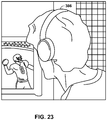
- H04S7/304—For headphones
-
- H—ELECTRICITY
- H04—ELECTRIC COMMUNICATION TECHNIQUE
- H04S—STEREOPHONIC SYSTEMS
- H04S7/00—Indicating arrangements; Control arrangements, e.g. balance control
- H04S7/40—Visual indication of stereophonic sound image
-
- G—PHYSICS
- G10—MUSICAL INSTRUMENTS; ACOUSTICS
- G10L—SPEECH ANALYSIS OR SYNTHESIS; SPEECH RECOGNITION; SPEECH OR VOICE PROCESSING; SPEECH OR AUDIO CODING OR DECODING
- G10L19/00—Speech or audio signals analysis-synthesis techniques for redundancy reduction, e.g. in vocoders; Coding or decoding of speech or audio signals, using source filter models or psychoacoustic analysis
- G10L2019/0001—Codebooks
- G10L2019/0004—Design or structure of the codebook
- G10L2019/0005—Multi-stage vector quantisation
-
- H—ELECTRICITY
- H04—ELECTRIC COMMUNICATION TECHNIQUE
- H04R—LOUDSPEAKERS, MICROPHONES, GRAMOPHONE PICK-UPS OR LIKE ACOUSTIC ELECTROMECHANICAL TRANSDUCERS; DEAF-AID SETS; PUBLIC ADDRESS SYSTEMS
- H04R2205/00—Details of stereophonic arrangements covered by H04R5/00 but not provided for in any of its subgroups
- H04R2205/021—Aspects relating to docking-station type assemblies to obtain an acoustical effect, e.g. the type of connection to external loudspeakers or housings, frequency improvement
-
- H—ELECTRICITY
- H04—ELECTRIC COMMUNICATION TECHNIQUE
- H04S—STEREOPHONIC SYSTEMS
- H04S2400/00—Details of stereophonic systems covered by H04S but not provided for in its groups
- H04S2400/01—Multi-channel, i.e. more than two input channels, sound reproduction with two speakers wherein the multi-channel information is substantially preserved
-
- H—ELECTRICITY
- H04—ELECTRIC COMMUNICATION TECHNIQUE
- H04S—STEREOPHONIC SYSTEMS
- H04S2400/00—Details of stereophonic systems covered by H04S but not provided for in its groups
- H04S2400/15—Aspects of sound capture and related signal processing for recording or reproduction
-
- H—ELECTRICITY
- H04—ELECTRIC COMMUNICATION TECHNIQUE
- H04S—STEREOPHONIC SYSTEMS
- H04S2420/00—Techniques used stereophonic systems covered by H04S but not provided for in its groups
- H04S2420/01—Enhancing the perception of the sound image or of the spatial distribution using head related transfer functions [HRTF's] or equivalents thereof, e.g. interaural time difference [ITD] or interaural level difference [ILD]
-
- H—ELECTRICITY
- H04—ELECTRIC COMMUNICATION TECHNIQUE
- H04S—STEREOPHONIC SYSTEMS
- H04S2420/00—Techniques used stereophonic systems covered by H04S but not provided for in its groups
- H04S2420/03—Application of parametric coding in stereophonic audio systems
-
- H—ELECTRICITY
- H04—ELECTRIC COMMUNICATION TECHNIQUE
- H04S—STEREOPHONIC SYSTEMS
- H04S2420/00—Techniques used stereophonic systems covered by H04S but not provided for in its groups
- H04S2420/11—Application of ambisonics in stereophonic audio systems
Definitions
- This disclosure relate to audio data and, more specifically, compression of audio data.
- a higher order ambisonics (HOA) signal (often represented by a plurality of spherical harmonic coefficients (SHC) or other hierarchical elements) is a three-dimensional representation of a soundfield.
- This HOA or SHC representation may represent this soundfield in a manner that is independent of the local speaker geometry used to playback a multi-channel audio signal rendered from this SHC signal.
- This SHC signal may also facilitate backwards compatibility as this SHC signal may be rendered to well-known and highly adopted multi-channel formats, such as a 5.1 audio channel format or a 7.1 audio channel format.
- the SHC representation may therefore enable a better representation of a soundfield that also accommodates backward compatibility.
- EP 2 234 104 A1 discloses quantizing first vectors representing a sound field and further compensating for quantization error introduced into the first vectors in second vectors that are also representative of the same sound field.
- a method comprises obtaining one or more first vectors describing distinct components of the soundfield and one or more second vectors describing background components of the soundfield, both the one or more first vectors and the one or more second vectors generated at least by performing a transformation with respect to the plurality of spherical harmonic coefficients.
- a device comprises one or more processors configured to determine one or more first vectors describing distinct components of the soundfield and one or more second vectors describing background components of the soundfield, both the one or more first vectors and the one or more second vectors generated at least by performing a transformation with respect to the plurality of spherical harmonic coefficients.
- a device comprises means for obtaining one or more first vectors describing distinct components of the soundfield and one or more second vectors describing background components of the soundfield, both the one or more first vectors and the one or more second vectors generated at least by performing a transformation with respect to the plurality of spherical harmonic coefficients, and means for storing the one or more first vectors.
- a non-transitory computer-readable storage medium has stored thereon instructions that, when executed, cause one or more processors to obtain one or more first vectors describing distinct components of the soundfield and one or more second vectors describing background components of the soundfield, both the one or more first vectors and the one or more second vectors generated at least by performing a transformation with respect to the plurality of spherical harmonic coefficients.
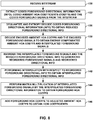
- a method comprises selecting one of a plurality of decompression schemes based on the indication of whether an compressed version of spherical harmonic coefficients representative of a sound field are generated from a synthetic audio object, and decompressing the compressed version of the spherical harmonic coefficients using the selected one of the plurality of decompression schemes.
- a device comprises one or more processors configured to select one of a plurality of decompression schemes based on the indication of whether an compressed version of spherical harmonic coefficients representative of a sound field are generated from a synthetic audio object, and decompress the compressed version of the spherical harmonic coefficients using the selected one of the plurality of decompression schemes.
- a device comprises means for selecting one of a plurality of decompression schemes based on the indication of whether an compressed version of spherical harmonic coefficients representative of a sound field are generated from a synthetic audio object, and means for decompressing the compressed version of the spherical harmonic coefficients using the selected one of the plurality of decompression schemes.
- a non-transitory computer-readable storage medium has stored thereon instructions that, when executed, cause one or more processors of an integrated decoding device to select one of a plurality of decompression schemes based on the indication of whether an compressed version of spherical harmonic coefficients representative of a sound field are generated from a synthetic audio object, and decompress the compressed version of the spherical harmonic coefficients using the selected one of the plurality of decompression schemes.
- a method comprises obtaining an indication of whether spherical harmonic coefficients representative of a sound field are generated from a synthetic audio object.
- a device comprises one or more processors configured to obtain an indication of whether spherical harmonic coefficients representative of a sound field are generated from a synthetic audio object.
- a device comprises means for storing spherical harmonic coefficients representative of a sound field, and means for obtaining an indication of whether the spherical harmonic coefficients are generated from a synthetic audio object.
- anon-transitory computer-readable storage medium has stored thereon instructions that, when executed, cause one or more processors to obtain an indication of whether spherical harmonic coefficients representative of a sound field are generated from a synthetic audio object.
- a method comprises quantizing one or more first vectors representative of one or more components of a sound field, and compensating for error introduced due to the quantization of the one or more first vectors in one or more second vectors that are also representative of the same one or more components of the sound field.
- a device comprises one or more processors configured to quantize one or more first vectors representative of one or more components of a sound field, and compensate for error introduced due to the quantization of the one or more first vectors in one or more second vectors that are also representative of the same one or more components of the sound field.
- a device comprises means for quantizing one or more first vectors representative of one or more components of a sound field, and means for compensating for error introduced due to the quantization of the one or more first vectors in one or more second vectors that are also representative of the same one or more components of the sound field.
- a non-transitory computer-readable storage medium has stored thereon instructions that, when executed, cause one or more processors to quantize one or more first vectors representative of one or more components of a sound field, and compensate for error introduced due to the quantization of the one or more first vectors in one or more second vectors that are also representative of the same one or more components of the sound field.
- a method comprises performing, based on a target bitrate, order reduction with respect to a plurality of spherical harmonic coefficients or decompositions thereof to generate reduced spherical harmonic coefficients or the reduced decompositions thereof, wherein the plurality of spherical harmonic coefficients represent a sound field.
- a device comprises one or more processors configured to perform, based on a target bitrate, order reduction with respect to a plurality of spherical harmonic coefficients or decompositions thereof to generate reduced spherical harmonic coefficients or the reduced decompositions thereof, wherein the plurality of spherical harmonic coefficients represent a sound field.
- a device comprises means for storing a plurality of spherical harmonic coefficients or decompositions thereof, and means for performing, based on a target bitrate, order reduction with respect to the plurality of spherical harmonic coefficients or decompositions thereof to generate reduced spherical harmonic coefficients or the reduced decompositions thereof, wherein the plurality of spherical harmonic coefficients represent a sound field.
- a non-transitory computer-readable storage medium has stored thereon instructions that, when executed, cause one or more processors to perform, based on a target bitrate, order reduction with respect to a plurality of spherical harmonic coefficients or decompositions thereof to generate reduced spherical harmonic coefficients or the reduced decompositions thereof, wherein the plurality of spherical harmonic coefficients represent a sound field.
- a method comprises obtaining a first non-zero set of coefficients of a vector that represent a distinct component of the sound field, the vector having been decomposed from a plurality of spherical harmonic coefficients that describe a sound field.
- a device comprises one or more processors configured to obtain a first non-zero set of coefficients of a vector that represent a distinct component of a sound field, the vector having been decomposed from a plurality of spherical harmonic coefficients that describe the sound field.
- a device comprises means for obtaining a first non-zero set of coefficients of a vector that represent a distinct component of a sound field, the vector having been decomposed from a plurality of spherical harmonic coefficients that describe the sound field, and means for storing the first non-zero set of coefficients.
- a non-transitory computer-readable storage medium has stored thereon instructions that, when executed, cause one or more processors to determine a first non-zero set of coefficients of a vector that represent a distinct component of a sound field, the vector having been decomposed from a plurality of spherical harmonic coefficients that describe the sound field.
- a method comprises obtaining, from a bitstream, at least one of one or more vectors decomposed from spherical harmonic coefficients that were recombined with background spherical harmonic coefficients, wherein the spherical harmonic coefficients describe a sound field, and wherein the background spherical harmonic coefficients described one or more background components of the same sound field.
- a device comprises one or more processors configured to determine, from a bitstream, at least one of one or more vectors decomposed from spherical harmonic coefficients that were recombined with background spherical harmonic coefficients, wherein the spherical harmonic coefficients describe a sound field, and wherein the background spherical harmonic coefficients described one or more background components of the same sound field.
- a device comprises means for obtaining , from a bitstream, at least one of one or more vectors decomposed from spherical harmonic coefficients that were recombined with background spherical harmonic coefficients, wherein the spherical harmonic coefficients describe a sound field, and wherein the background spherical harmonic coefficients described one or more background components of the same sound field.
- a non-transitory computer-readable storage medium has stored thereon instructions that, when executed, cause one or more processors to obtain, from a bitstream, at least one of one or more vectors decomposed from spherical harmonic coefficients that were recombined with background spherical harmonic coefficients, wherein the spherical harmonic coefficients describe a sound field, and wherein the background spherical harmonic coefficients described one or more background components of the same sound field.
- a method comprises identifying one or more distinct audio objects from one or more spherical harmonic coefficients (SHC) associated with the audio objects based on a directionality determined for one or more of the audio objects.
- SHC spherical harmonic coefficients
- a device comprises one or more processors configured to identify one or more distinct audio objects from one or more spherical harmonic coefficients (SHC) associated with the audio objects based on a directionality determined for one or more of the audio objects.
- SHC spherical harmonic coefficients
- a device comprises means for storing one or more spherical harmonic coefficients (SHC), and means for identifying one or more distinct audio objects from the one or more spherical harmonic coefficients (SHC) associated with the audio objects based on a directionality determined for one or more of the audio objects.
- SHC spherical harmonic coefficients
- a non-transitory computer-readable storage medium has stored thereon instructions that, when executed, cause one or more processors to identify one or more distinct audio objects from one or more spherical harmonic coefficients (SHC) associated with the audio objects based on a directionality determined for one or more of the audio objects.
- SHC spherical harmonic coefficients
- a method comprises performing a vector-based synthesis with respect to a plurality of spherical harmonic coefficients to generate decomposed representations of the plurality of spherical harmonic coefficients representative of one or more audio objects and corresponding directional information, wherein the spherical harmonic coefficients are associated with an order and describe a sound field, determining distinct and background directional information from the directional information, reducing an order of the directional information associated with the background audio objects to generate transformed background directional information, applying compensation to increase values of the transformed directional information to preserve an overall energy of the sound field.
- a device comprises one or more processors configured to perform a vector-based synthesis with respect to a plurality of spherical harmonic coefficients to generate decomposed representations of the plurality of spherical harmonic coefficients representative of one or more audio objects and corresponding directional information, wherein the spherical harmonic coefficients are associated with an order and describe a sound field, determine distinct and background directional information from the directional information, reduce an order of the directional information associated with the background audio objects to generate transformed background directional information, apply compensation to increase values of the transformed directional information to preserve an overall energy of the sound field.
- a device comprises means for performing a vector-based synthesis with respect to a plurality of spherical harmonic coefficients to generate decomposed representations of the plurality of spherical harmonic coefficients representative of one or more audio objects and corresponding directional information, wherein the spherical harmonic coefficients are associated with an order and describe a sound field, means for determining distinct and background directional information from the directional information, means for reducing an order of the directional information associated with the background audio objects to generate transformed background directional information, and means for applying compensation to increase values of the transformed directional information to preserve an overall energy of the sound field.
- a non-transitory computer-readable storage medium has stored thereon instructions that, when executed, cause one or more processors to perform a vector-based synthesis with respect to a plurality of spherical harmonic coefficients to generate decomposed representations of the plurality of spherical harmonic coefficients representative of one or more audio objects and corresponding directional information, wherein the spherical harmonic coefficients are associated with an order and describe a sound field, determine distinct and background directional information from the directional information, reduce an order of the directional information associated with the background audio objects to generate transformed background directional information, and apply compensation to increase values of the transformed directional information to preserve an overall energy of the sound field.
- a method comprises obtaining decomposed interpolated spherical harmonic coefficients for a time segment by, at least in part, performing an interpolation with respect to a first decomposition of a first plurality of spherical harmonic coefficients and a second decomposition of a second plurality of spherical harmonic coefficients.
- a device comprises one or more processors configured to obtain decomposed interpolated spherical harmonic coefficients for a time segment by, at least in part, performing an interpolation with respect to a first decomposition of a first plurality of spherical harmonic coefficients and a second decomposition of a second plurality of spherical harmonic coefficients.
- a device comprises means for storing a first plurality of spherical harmonic coefficients and a second plurality of spherical harmonic coefficients, and means for obtain decomposed interpolated spherical harmonic coefficients for a time segment by, at least in part, performing an interpolation with respect to a first decomposition of the first plurality of spherical harmonic coefficients and the second decomposition of a second plurality of spherical harmonic coefficients.
- a non-transitory computer-readable storage medium has stored thereon instructions that, when executed, cause one or more processors to obtain decomposed interpolated spherical harmonic coefficients for a time segment by, at least in part, performing an interpolation with respect to a first decomposition of a first plurality of spherical harmonic coefficients and a second decomposition of a second plurality of spherical harmonic coefficients.
- a method comprises obtaining a bitstream comprising a compressed version of a spatial component of a sound field, the spatial component generated by performing a vector based synthesis with respect to a plurality of spherical harmonic coefficients.
- a device comprises one or more processors configured to obtain a bitstream comprising a compressed version of a spatial component of a sound field, the spatial component generated by performing a vector based synthesis with respect to a plurality of spherical harmonic coefficients.
- a device comprises means for obtaining a bitstream comprising a compressed version of a spatial component of a sound field, the spatial component generated by performing a vector based synthesis with respect to a plurality of spherical harmonic coefficients, and means for storing the bitstream.
- a non-transitory computer-readable storage medium has stored thereon instructions that when executed cause one or more processors to obtain a bitstream comprising a compressed version of a spatial component of a sound field, the spatial component generated by performing a vector based synthesis with respect to a plurality of spherical harmonic coefficients.
- a method comprises generating a bitstream comprising a compressed version of a spatial component of a sound field, the spatial component generated by performing a vector based synthesis with respect to a plurality of spherical harmonic coefficients.
- a device comprises one or more processors configured to generate a bitstream comprising a compressed version of a spatial component of a sound field, the spatial component generated by performing a vector based synthesis with respect to a plurality of spherical harmonic coefficients.
- a device comprises means for generating a bitstream comprising a compressed version of a spatial component of a sound field, the spatial component generated by performing a vector based synthesis with respect to a plurality of spherical harmonic coefficients, and means for storing the bitstream.
- a non-transitory computer-readable storage medium has instructions that when executed cause one or more processors to generate a bitstream comprising a compressed version of a spatial component of a sound field, the spatial component generated by performing a vector based synthesis with respect to a plurality of spherical harmonic coefficients.
- a method comprises identifying a Huffman codebook to use when decompressing a compressed version of a spatial component of a plurality of compressed spatial components based on an order of the compressed version of the spatial component relative to remaining ones of the plurality of compressed spatial components, the spatial component generated by performing a vector based synthesis with respect to a plurality of spherical harmonic coefficients.
- a device comprises one or more processors configured to identify a Huffman codebook to use when decompressing a compressed version of a spatial component of a plurality of compressed spatial components based on an order of the compressed version of the spatial component relative to remaining ones of the plurality of compressed spatial components, the spatial component generated by performing a vector based synthesis with respect to a plurality of spherical harmonic coefficients.
- a device comprises means for identifying a Huffman codebook to use when decompressing a compressed version of a spatial component of a plurality of compressed spatial components based on an order of the compressed version of the spatial component relative to remaining ones of the plurality of compressed spatial components, the spatial component generated by performing a vector based synthesis with respect to a plurality of spherical harmonic coefficients, and means for string the plurality of compressed spatial components.
- a non-transitory computer-readable storage medium has stored thereon instructions that when executed cause one or more processors to identify a Huffman codebook to use when decompressing a spatial component of a plurality of spatial components based on an order of the spatial component relative to remaining ones of the plurality of spatial components, the spatial component generated by performing a vector based synthesis with respect to a plurality of spherical harmonic coefficients.
- a method comprises identifying a Huffman codebook to use when compressing a spatial component of a plurality of spatial components based on an order of the spatial component relative to remaining ones of the plurality of spatial components, the spatial component generated by performing a vector based synthesis with respect to a plurality of spherical harmonic coefficients.
- a device comprises one or more processors configured to identify a Huffman codebook to use when compressing a spatial component of a plurality of spatial components based on an order of the spatial component relative to remaining ones of the plurality of spatial components, the spatial component generated by performing a vector based synthesis with respect to a plurality of spherical harmonic coefficients.
- a device comprises means for storing a Huffman codebook, and means for identifying the Huffman codebook to use when compressing a spatial component of a plurality of spatial components based on an order of the spatial component relative to remaining ones of the plurality of spatial components, the spatial component generated by performing a vector based synthesis with respect to a plurality of spherical harmonic coefficients.
- a non-transitory computer-readable storage medium has stored thereon instructions that, when executed, cause one or more processors to identify a Huffman codebook to use when compressing a spatial component of a plurality of spatial components based on an order of the spatial component relative to remaining ones of the plurality of spatial components, the spatial component generated by performing a vector based synthesis with respect to a plurality of spherical harmonic coefficients.
- a method comprises determining a quantization step size to be used when compressing a spatial component of a sound field, the spatial component generated by performing a vector based synthesis with respect to a plurality of spherical harmonic coefficients.
- a device comprises one or more processors configured to determine a quantization step size to be used when compressing a spatial component of a sound field, the spatial component generated by performing a vector based synthesis with respect to a plurality of spherical harmonic coefficients.
- a device comprises means for determining a quantization step size to be used when compressing a spatial component of a sound field, the spatial component generated by performing a vector based synthesis with respect to a plurality of spherical harmonic coefficients, and means for storing the quantization step size.
- a non-transitory computer-readable storage medium has stored thereon instructions that when executed cause one or more processors to determine a quantization step size to be used when compressing a spatial component of a sound field, the spatial component generated by performing a vector based synthesis with respect to a plurality of spherical harmonic coefficients.
- surround sound formats are mostly 'channel' based in that they implicitly specify feeds to loudspeakers in certain geometrical coordinates.
- These include the popular 5.1 format (which includes the following six channels: front left (FL), front right (FR), center or front center, back left or surround left, back right or surround right, and low frequency effects (LFE)), the growing 7.1 format, various formats that includes height speakers such as the 7.1.4 format and the 22.2 format (e.g., for use with the Ultra High Definition Television standard).
- Non-consumer formats can span any number of speakers (in symmetric and non-symmetric geometries) often termed 'surround arrays'.
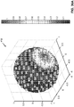
- One example of such an array includes 32 loudspeakers positioned on co-ordinates on the corners of a truncated icosohedron.
- the input to a future MPEG encoder is optionally one of three possible formats: (i) traditional channel-based audio (as discussed above), which is meant to be played through loudspeakers at pre-specified positions; (ii) object-based audio, which involves discrete pulse-code-modulation (PCM) data for single audio objects with associated metadata containing their location coordinates (amongst other information); and (iii) scene-based audio, which involves representing the soundfield using coefficients of spherical harmonic basis functions (also called “spherical harmonic coefficients" or SHC, "Higher Order Ambisonics” or HOA, and "HOA coefficients").
- PCM pulse-code-modulation
- a hierarchical set of elements may be used to represent a soundfield.
- the hierarchical set of elements may refer to a set of elements in which the elements are ordered such that a basic set of lower-ordered elements provides a full representation of the modeled soundfield. As the set is extended to include higher-order elements, the representation becomes more detailed, increasing resolution.
- SHC spherical harmonic coefficients
- the term in square brackets is a frequency-domain representation of the signal (i.e., S ( ⁇ , r r , ⁇ r , ⁇ r )) which can be approximated by various time-frequency transformations, such as the discrete Fourier transform (DFT), the discrete cosine transform (DCT), or a wavelet transform.
- DFT discrete Fourier transform
- DCT discrete cosine transform
- wavelet transform a frequency-domain representation of the signal
- hierarchical sets include sets of wavelet transform coefficients and other sets of coefficients of multiresolution basis functions.
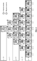
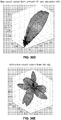
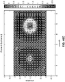
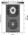
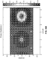
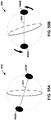
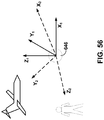
- the spherical harmonic basis functions are shown in three-dimensional coordinate space with both the order and the suborder shown.
- the SHC A n m k can either be physically acquired (e.g., recorded) by various microphone array configurations or, alternatively, they can be derived from channel-based or object-based descriptions of the soundfield.
- the SHC represent scene-based audio, where the SHC may be input to an audio encoder to obtain encoded SHC that may promote more efficient transmission or storage. For example, a fourth-order representation involving (1+4) 2 (25, and hence fourth order) coefficients may be used.
- the SHC may be derived from a microphone recording using a microphone.
- Various examples of how SHC may be derived from microphone arrays are described in Poletti, M., "Three-Dimensional Surround Sound Systems Based on Spherical Harmonics," J. Audio Eng. Soc., Vol. 53, No. 11, 2005 November, pp. 1004-1025 .
- a n m k g ⁇ ⁇ 4 ⁇ ik h n 2 kr s Y n m * ⁇ s ⁇ s , where i is ⁇ 1 , h n 2 ⁇ is the spherical Hankel function (of the second kind) of order n, and ⁇ r s , ⁇ s , ⁇ s ⁇ is the location of the object.
- Knowing the object source energy g ( ⁇ ) as a function of frequency allows us to convert each PCM object and its location into the SHC A n m k . Further, it can be shown (since the above is a linear and orthogonal decomposition) that the A n m k coefficients for each object are additive. In this manner, a multitude of PCM objects can be represented by the A n m k coefficients (e.g., as a sum of the coefficient vectors for the individual objects).
- these coefficients contain information about the soundfield (the pressure as a function of 3D coordinates), and the above represents the transformation from individual objects to a representation of the overall soundfield, in the vicinity of the observation point ⁇ r r , ⁇ r , ⁇ r ⁇ .
- the remaining figures are described below in the context of object-based and SHC-based audio coding.
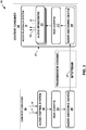
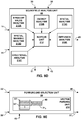
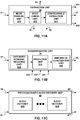
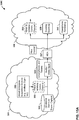
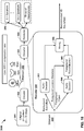
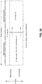
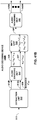
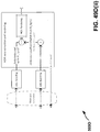
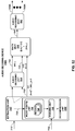
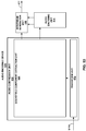
- FIG. 3 is a diagram illustrating a system 10 that may perform various aspects of the techniques described in this disclosure.
- the system 10 includes a content creator 12 and a content consumer 14. While described in the context of the content creator 12 and the content consumer 14, the techniques may be implemented in any context in which SHCs (which may also be referred to as HOA coefficients) or any other hierarchical representation of a soundfield are encoded to form a bitstream representative of the audio data.
- the content creator 12 may represent any form of computing device capable of implementing the techniques described in this disclosure, including a handset (or cellular phone), a tablet computer, a smart phone, or a desktop computer to provide a few examples.
- the content consumer 14 may represent any form of computing device capable of implementing the techniques described in this disclosure, including a handset (or cellular phone), a tablet computer, a smart phone, a set-top box, or a desktop computer to provide a few examples.
- the content creator 12 may represent a movie studio or other entity that may generate multi-channel audio content for consumption by content consumers, such as the content consumer 14.
- the content creator 12 may represent an individual user who would like to compress HOA coefficients 11. Often, this content creator generates audio content in conjunction with video content.
- the content consumer 14 represents an individual that owns or has access to an audio playback system, which may refer to any form of audio playback system capable of rendering SHC for play back as multi-channel audio content.
- the content consumer 14 includes an audio playback system 16.
- the content creator 12 includes an audio editing system 18.
- the content creator 12 obtain live recordings 7 in various formats (including directly as HOA coefficients) and audio objects 9, which the content creator 12 may edit using audio editing system 18.
- the content creator may, during the editing process, render HOA coefficients 11 from audio objects 9, listening to the rendered speaker feeds in an attempt to identify various aspects of the soundfield that require further editing.
- the content creator 12 may then edit HOA coefficients 11 (potentially indirectly through manipulation of different ones of the audio objects 9 from which the source HOA coefficients may be derived in the manner described above).
- the content creator 12 may employ the audio editing system 18 to generate the HOA coefficients 11.
- the audio editing system 18 represents any system capable of editing audio data and outputting this audio data as one or more source spherical harmonic coefficients.
- the content creator 12 may generate a bitstream 21 based on the HOA coefficients 11. That is, the content creator 12 includes an audio encoding device 20 that represents a device configured to encode or otherwise compress HOA coefficients 11 in accordance with various aspects of the techniques described in this disclosure to generate the bitstream 21.
- the audio encoding device 20 may generate the bitstream 21 for transmission, as one example, across a transmission channel, which may be a wired or wireless channel, a data storage device, or the like.
- the bitstream 21 may represent an encoded version of the HOA coefficients 11 and may include a primary bitstream and another side bitstream, which may be referred to as side channel information.
- the audio encoding device 20 may be configured to encode the HOA coefficients 11 based on a vector-based synthesis or a directional-based synthesis. To determine whether to perform the vector-based synthesis methodology or a directional-based synthesis methodology, the audio encoding device 20 may determine, based at least in part on the HOA coefficients 11, whether the HOA coefficients 11 were generated via a natural recording of a soundfield (e.g., live recording 7) or produced artificially (i.e., synthetically) from, as one example, audio objects 9, such as a PCM object. When the HOA coefficients 11 were generated form the audio objects 9, the audio encoding device 20 may encode the HOA coefficients 11 using the directional-based synthesis methodology.
- a natural recording of a soundfield e.g., live recording 7
- audio objects 9 such as a PCM object
- the audio encoding device 20 may encode the HOA coefficients 11 based on the vector-based synthesis methodology.
- vector-based or directional-based synthesis methodology may be deployed. There may be other cases where either or both may be useful for natural recordings, artificially generated content or a mixture of the two (hybrid content).
- both methodologies simultaneously for coding a single time-frame of HOA coefficients.
- the audio encoding device 20 may be configured to encode the HOA coefficients 11 using a vector-based synthesis methodology involving application of a linear invertible transform (LIT).
- LIT linear invertible transform
- One example of the linear invertible transform is referred to as a "singular value decomposition" (or "SVD").
- SVD singular value decomposition
- the audio encoding device 20 may apply SVD to the HOA coefficients 11 to determine a decomposed version of the HOA coefficients 11.
- the audio encoding device 20 may then analyze the decomposed version of the HOA coefficients 11 to identify various parameters, which may facilitate reordering of the decomposed version of the HOA coefficients 11.
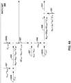
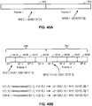
- the audio encoding device 20 may then reorder the decomposed version of the HOA coefficients 11 based on the identified parameters, where such reordering, as described in further detail below, may improve coding efficiency given that the transformation may reorder the HOA coefficients across frames of the HOA coefficients (where a frame commonly includes M samples of the HOA coefficients 11 and M is, in some examples, set to 1024).
- the audio encoding device 20 may select those of the decomposed version of the HOA coefficients 11 representative of foreground (or, in other words, distinct, predominant or salient) components of the soundfield.
- the audio encoding device 20 may specify the decomposed version of the HOA coefficients 11 representative of the foreground components as an audio object and associated directional information.
- the audio encoding device 20 may also perform a soundfield analysis with respect to the HOA coefficients 11 in order, at least in part, to identify those of the HOA coefficients 11 representative of one or more background (or, in other words, ambient) components of the soundfield.
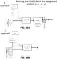
- the audio encoding device 20 may perform energy compensation with respect to the background components given that, in some examples, the background components may only include a subset of any given sample of the HOA coefficients 11 (e.g., such as those corresponding to zero and first order spherical basis functions and not those corresponding to second or higher order spherical basis functions).
- the audio encoding device 20 may augment (e.g., add/subtract energy to/from) the remaining background HOA coefficients of the HOA coefficients 11 to compensate for the change in overall energy that results from performing the order reduction.
- the audio encoding device 20 may next perform a form of psychoacoustic encoding (such as MPEG surround, MPEG-AAC, MPEG-USAC or other known forms of psychoacoustic encoding) with respect to each of the HOA coefficients 11 representative of background components and each of the foreground audio objects.
- the audio encoding device 20 may perform a form of interpolation with respect to the foreground directional information and then perform an order reduction with respect to the interpolated foreground directional information to generate order reduced foreground directional information.
- the audio encoding device 20 may further perform, in some examples, a quantization with respect to the order reduced foreground directional information, outputting coded foreground directional information.
- this quantization may comprise a scalar/entropy quantization.
- the audio encoding device 20 may then form the bitstream 21 to include the encoded background components, the encoded foreground audio objects, and the quantized directional information.
- the audio encoding device 20 may then transmit or otherwise output the bitstream 21 to the content consumer 14.
- the content creator 12 may output the bitstream 21 to an intermediate device positioned between the content creator 12 and the content consumer 14.
- This intermediate device may store the bitstream 21 for later delivery to the content consumer 14, which may request this bitstream.
- the intermediate device may comprise a file server, a web server, a desktop computer, a laptop computer, a tablet computer, a mobile phone, a smart phone, or any other device capable of storing the bitstream 21 for later retrieval by an audio decoder.
- This intermediate device may reside in a content delivery network capable of streaming the bitstream 21 (and possibly in conjunction with transmitting a corresponding video data bitstream) to subscribers, such as the content consumer 14, requesting the bitstream 21.
- the content creator 12 may store the bitstream 21 to a storage medium, such as a compact disc, a digital video disc, a high definition video disc or other storage media, most of which are capable of being read by a computer and therefore may be referred to as computer-readable storage media or non-transitory computer-readable storage media.
- a storage medium such as a compact disc, a digital video disc, a high definition video disc or other storage media, most of which are capable of being read by a computer and therefore may be referred to as computer-readable storage media or non-transitory computer-readable storage media.
- the transmission channel may refer to those channels by which content stored to these mediums are transmitted (and may include retail stores and other store-based delivery mechanism). In any event, the techniques of this disclosure should not therefore be limited in this respect to the example of FIG. 3 .
- the content consumer 14 includes the audio playback system 16.
- the audio playback system 16 may represent any audio playback system capable of playing back multi-channel audio data.
- the audio playback system 16 may include a number of different renderers 22.
- the renderers 22 may each provide for a different form of rendering, where the different forms of rendering may include one or more of the various ways of performing vector-base amplitude panning (VBAP), and/or one or more of the various ways of performing soundfield synthesis.
- VBAP vector-base amplitude panning
- a and/or B means "A or B", or both "A and B".
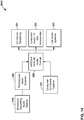
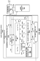
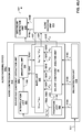
- the audio playback system 16 may further include an audio decoding device 24.
- the audio decoding device 24 may represent a device configured to decode HOA coefficients 11' from the bitstream 21, where the HOA coefficients 11' may be similar to the HOA coefficients 11 but differ due to lossy operations (e.g., quantization) and/or transmission via the transmission channel. That is, the audio decoding device 24 may dequantize the foreground directional information specified in the bitstream 21, while also performing psychoacoustic decoding with respect to the foreground audio objects specified in the bitstream 21 and the encoded HOA coefficients representative of background components.
- the audio decoding device 24 may further perform interpolation with respect to the decoded foreground directional information and then determine the HOA coefficients representative of the foreground components based on the decoded foreground audio objects and the interpolated foreground directional information. The audio decoding device 24 may then determine the HOA coefficients 11' based on the determined HOA coefficients representative of the foreground components and the decoded HOA coefficients representative of the background components.
- the audio playback system 16 may, after decoding the bitstream 21 to obtain the HOA coefficients 11' and render the HOA coefficients 11' to output loudspeaker feeds 25.
- the loudspeaker feeds 25 may drive one or more loudspeakers (which are not shown in the example of FIG. 3 for ease of illustration purposes).
- the audio playback system 16 may obtain loudspeaker information 13 indicative of a number of loudspeakers and/or a spatial geometry of the loudspeakers. In some instances, the audio playback system 16 may obtain the loudspeaker information 13 using a reference microphone and driving the loudspeakers in such a manner as to dynamically determine the loudspeaker information 13. In other instances or in conjunction with the dynamic determination of the loudspeaker information 13, the audio playback system 16 may prompt a user to interface with the audio playback system 16 and input the loudspeaker information 16.
- the audio playback system 16 may then select one of the audio renderers 22 based on the loudspeaker information 13. In some instances, the audio playback system 16 may, when none of the audio renderers 22 are within some threshold similarity measure (loudspeaker geometry wise) to that specified in the loudspeaker information 13, the audio playback system 16 may generate the one of audio renderers 22 based on the loudspeaker information 13. The audio playback system 16 may, in some instances, generate the one of audio renderers 22 based on the loudspeaker information 13 without first attempting to select an existing one of the audio renderers 22.
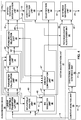
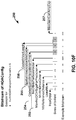
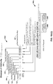
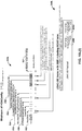
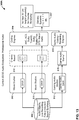
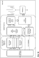
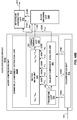
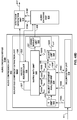
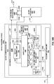
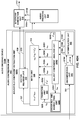
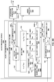
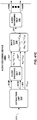
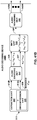
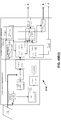
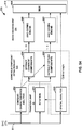
- FIG. 4 is a block diagram illustrating, in more detail, one example of the audio encoding device 20 shown in the example of FIG. 3 that may perform various aspects of the techniques described in this disclosure.
- the audio encoding device 20 includes a content analysis unit 26, a vector-based synthesis methodology unit 27 and a directional-based synthesis methodology unit 28.
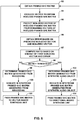
- the content analysis unit 26 represents a unit configured to analyze the content of the HOA coefficients 11 to identify whether the HOA coefficients 11 represent content generated from a live recording or an audio object.
- the content analysis unit 26 may determine whether the HOA coefficients 11 were generated from a recording of an actual soundfield or from an artificial audio object.
- the content analysis unit 26 may make this determination in various ways. For example, the content analysis unit 26 may code (N+1) 2 -1 channels and predict the last remaining channel (which may be represented as a vector).
- the content analysis unit 26 may apply scalars to at least some of the (N+1) 2 -1 channels and add the resulting values to determine the last remaining channel. Furthermore, in this example, the content analysis unit 26 may determine an accuracy of the predicted channel.
- the HOA coefficients 11 are likely to be generated from a synthetic audio object. In contrast, if the accuracy of the predicted channel is relatively low (e.g., the accuracy is below the particular threshold), the HOA coefficients 11 are more likely to represent a recorded soundfield. For instance, in this example, if a signal-to-noise ratio (SNR) of the predicted channel is over 100 decibels (dbs), the HOA coefficients 11 are more likely to represent a soundfield generated from a synthetic audio object. In contrast, the SNR of a soundfield recorded using an eigen microphone may be 5 to 20 dbs. Thus, there may be an apparent demarcation in SNR ratios between soundfield represented by the HOA coefficients 11 generated from an actual direct recording and from a synthetic audio object.
- SNR signal-to-noise ratio
- the content analysis unit 26 may then predicted the first non-zero vector of the reduced framed HOA coefficients from remaining vectors of the reduced framed HOA coefficients.
- the first non-zero vector may refer to a first vector going from the first-order (and considering each of the order-dependent sub-orders) to the fourth-order (and considering each of the order-dependent sub-orders) that has values other than zero.
- the first non-zero vector of the reduced framed HOA coefficients refers to those of HOA coefficients 11 associated with the first order, zero-sub-order spherical harmonic basis function. While described with respect to the first non-zero vector, the techniques may predict other vectors of the reduced framed HOA coefficients from the remaining vectors of the reduced framed HOA coefficients.
- the content analysis unit 26 may predict those of the reduced framed HOA coefficients associated with a first-order, first-sub-order spherical harmonic basis function or a first-order, negative-first-order spherical harmonic basis function. As yet other examples, the content analysis unit 26 may predict those of the reduced framed HOA coefficients associated with a second-order, zero-order spherical harmonic basis function.
- the content analysis unit 26 may operate in accordance with the following equation: ⁇ i ⁇ i v i , where i is from 1 to (N + 1) 2 -2, which is 23 for a fourth order representation, ⁇ i denotes some constant for the i -th vector, and v i refers to the i -th vector.
- the content analysis unit 26 may obtain an error based on the predicted first non-zero vector and the actual non-zero vector. In some examples, the content analysis unit 26 subtracts the predicted first non-zero vector from the actual first non-zero vector to derive the error.
- the content analysis unit 26 may compute the error as a sum of the absolute value of the differences between each entry in the predicted first non-zero vector and the actual first non-zero vector.
- the content analysis unit 26 may compute a ratio based on an energy of the actual first non-zero vector and the error. The content analysis unit 26 may determine this energy by squaring each entry of the first non-zero vector and adding the squared entries to one another. The content analysis unit 26 may then compare this ratio to a threshold. When the ratio does not exceed the threshold, the content analysis unit 26 may determine that the framed HOA coefficients 11 is generated from a recording and indicate in the bitstream that the corresponding coded representation of the HOA coefficients 11 was generated from a recording. When the ratio exceeds the threshold, the content analysis unit 26 may determine that the framed HOA coefficients 11 is generated from a synthetic audio object and indicate in the bitstream that the corresponding coded representation of the framed HOA coefficients 11 was generated from a synthetic audio object.
- the indication of whether the framed HOA coefficients 11 was generated from a recording or a synthetic audio object may comprise a single bit for each frame.
- the single bit may indicate that different encodings were used for each frame effectively toggling between different ways by which to encode the corresponding frame.
- the content analysis unit 26 passes the HOA coefficients 11 to the vector-based synthesis unit 27.
- the content analysis unit 26 passes the HOA coefficients 11 to the directional-based synthesis unit 28.
- the directional-based synthesis unit 28 may represent a unit configured to perform a directional-based synthesis of the HOA coefficients 11 to generate a directional-based bitstream 21.
- the techniques are based on coding the HOA coefficients using a front-end classifier.
- the classifier may work as follows: Start with a framed SH matrix say 4 th order , frame size of 1024 , which may also be referred to as framed HOA coefficients or as HOA coefficients ⁇ where a matrix of size 25 ⁇ 1024 is obtained . Exclude the 1 st vector 0 th order SH ⁇ so there is a matrix of size 24 ⁇ 1024. Predict the first non ⁇ zero vector in the matrix a 1 ⁇ 1024 size vector ⁇ from the rest of the vectors in the matrix 23 vectors of size 1 ⁇ 1024 .
- the underlying soundfield (at that frame) is sparse/synthetic. Else, the underlying soundfield is a recorded (using say a mic array) soundfield.
- the decision is a 1 bit decision, that is sent over the bitstream for each frame.
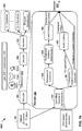
- the vector-based synthesis unit 27 may include a linear invertible transform (LIT) unit 30, a parameter calculation unit 32, a reorder unit 34, a foreground selection unit 36, an energy compensation unit 38, a psychoacoustic audio coder unit 40, a bitstream generation unit 42, a soundfield analysis unit 44, a coefficient reduction unit 46, a background (BG) selection unit 48, a spatio-temporal interpolation unit 50, and a quantization unit 52.
- LIT linear invertible transform
- the linear invertible transform (LIT) unit 30 receives the HOA coefficients 11 in the form of HOA channels, each channel representative of a block or frame of a coefficient associated with a given order, sub-order of the spherical basis functions (which may be denoted as HOA[ k ], where k may denote the current frame or block of samples).
- the matrix of HOA coefficients 11 may have dimensions D: M x ( N +1) 2 .
- the LIT unit 30 may represent a unit configured to perform a form of analysis referred to as singular value decomposition. While described with respect to SVD, the techniques described in this disclosure may be performed with respect to any similar transformation or decomposition that provides for sets of linearly uncorrelated, energy compacted output. Also, reference to "sets” in this disclosure is generally intended to refer to non-zero sets unless specifically stated to the contrary and is not intended to refer to the classical mathematical definition of sets that includes the so-called "empty set.”
- PCA principal component analysis
- Principal components Linearly uncorrelated variables represent variables that do not have a linear statistical relationship (or dependence) to one another.
- principal components may be described as having a small degree of statistical correlation to one another. In any event, the number of so-called principal components is less than or equal to the number of original variables.
- the transformation is defined in such a way that the first principal component has the largest possible variance (or, in other words, accounts for as much of the variability in the data as possible), and each succeeding component in turn has the highest variance possible under the constraint that this successive component be orthogonal to (which may be restated as uncorrelated with) the preceding components.
- PCA may perform a form of order-reduction, which in terms of the HOA coefficients 11 may result in the compression of the HOA coefficients 11.
- PCA may be referred to by a number of different names, such as discrete Karhunen-Loeve transform, the Hotelling transform, proper orthogonal decomposition (POD), and eigenvalue decomposition (EVD) to name a few examples.
- Properties of such operations that are conducive to the underlying goal of compressing audio data are 'energy compaction' and 'decorrelation' of the multichannel audio data.
- the LIT unit 30 performs a singular value decomposition (which, again, may be referred to as "SVD") to transform the HOA coefficients 11 into two or more sets of transformed HOA coefficients. These "sets" of transformed HOA coefficients may include vectors of transformed HOA coefficients.
- the LIT unit 30 may perform the SVD with respect to the HOA coefficients 11 to generate a so-called V matrix, an S matrix, and a U matrix.
- SVD in linear algebra, may represent a factorization of a y-by-z real or complex matrix X (where X may represent multi-channel audio data, such as the HOA coefficients 11) in the following form:
- X USV *
- U may represent an y-by-y real or complex unitary matrix, where the y columns of U are commonly known as the left-singular vectors of the multi-channel audio data.
- S may represent an y-by-z rectangular diagonal matrix with non-negative real numbers on the diagonal, where the diagonal values of S are commonly known as the singular values of the multi-channel audio data.
- V* (which may denote a conjugate transpose of V) may represent an z-by-z real or complex unitary matrix, where the z columns of V* are commonly known as the right-singular vectors of the multi-channel audio data.
- the techniques may be applied to any form of multi-channel audio data.
- the audio encoding device 20 may perform a singular value decomposition with respect to multi-channel audio data representative of at least a portion of soundfield to generate a U matrix representative of left-singular vectors of the multi-channel audio data, an S matrix representative of singular values of the multi-channel audio data and a V matrix representative of right-singular vectors of the multi-channel audio data, and representing the multi-channel audio data as a function of at least a portion of one or more of the U matrix, the S matrix and the V matrix.
- the V* matrix in the SVD mathematical expression referenced above is denoted as the conjugate transpose of the V matrix to reflect that SVD may be applied to matrices comprising complex numbers.
- the complex conjugate of the V matrix (or, in other words, the V* matrix) may be considered to be the transpose of the V matrix.
- the HOA coefficients 11 comprise real-numbers with the result that the V matrix is output through SVD rather than the V* matrix.
- reference to the V matrix should be understood to refer to the transpose of the V matrix where appropriate.
- the techniques may be applied in a similar fashion to HOA coefficients 11 having complex coefficients, where the output of the SVD is the V* matrix. Accordingly, the techniques should not be limited in this respect to only provide for application of SVD to generate a V matrix, but may include application of SVD to HOA coefficients 11 having complex components to generate a V* matrix.
- the LIT unit 30 may perform a block-wise form of SVD with respect to each block (which may refer to a frame) of higher-order ambisonics (HOA) audio data (where this ambisonics audio data includes blocks or samples of the HOA coefficients 11 or any other form of multi-channel audio data).
- HOA ambisonics
- M may be used to denote the length of an audio frame in samples. For example, when an audio frame includes 1024 audio samples, M equals 1024.
- the LIT unit 30 may therefore perform a block-wise SVD with respect to a block the HOA coefficients 11 having M-by-(N+1) 2 HOA coefficients, where N, again, denotes the order of the HOA audio data.
- the LIT unit 30 may generate, through performing this SVD, a V matrix, an S matrix, and a U matrix, where each of matrixes may represent the respective V, S and U matrixes described above.
- the linear invertible transform unit 30 may perform SVD with respect to the HOA coefficients 11 to output US[k] vectors 33 (which may represent a combined version of the S vectors and the U vectors) having dimensions D: M x ( N +1) 2 , and V[k] vectors 35 having dimensions D: ( N +1) 2 x ( N +1) 2 .
- US[k] vectors 33 which may represent a combined version of the S vectors and the U vectors
- V[k] vectors 35 having dimensions D: ( N +1) 2 x ( N +1) 2 .
- Individual vector elements in the US[k] matrix may also be termed X PS ( k ) while individual vectors of the V[k] matrix may also be termed v ( k ).
- U, S and V matrices may reveal that these matrices carry or represent spatial and temporal characteristics of the underlying soundfield represented above by X.
- Each of the N vectors in U may represent normalized separated audio signals as a function of time (for the time period represented by M samples), that are orthogonal to each other and that have been decoupled from any spatial characteristics (which may also be referred to as directional information).
- the spatial characteristics, representing spatial shape and position (r, theta, phi) width may instead be represented by individual i th vectors , v ( i ) ( k ), in the V matrix (each of length (N+1) 2 ).
- the LIT unit 30 may apply the linear invertible transform to derivatives of the HOA coefficients 11.
- the LIT unit 30 may apply SVD with respect to a power spectral density matrix derived from the HOA coefficients 11.
- PSD power spectral density matrix
- the hoaFrame notation refers to a frame of the HOA coefficients 11.
- the LIT unit 30 may, after applying the SVD (svd) to the PSD, may obtain an S[ k ] 2 matrix (S_squared) and a V[ k ] matrix.
- the S[ k ] 2 matrix may denote a squared S[k] matrix, whereupon the LIT unit 30 may apply a square root operation to the S[ k ] 2 matrix to obtain the S[k] matrix.
- the LIT unit 30 may, in some instances, perform quantization with respect to the V[ k ] matrix to obtain a quantized V[ k ] matrix (which may be denoted as V[ k ]' matrix).
- the LIT unit 30 may obtain the U[k] matrix by first multiplying the S[ k ] matrix by the quantized V[ k ]' matrix to obtain an SV [k]' matrix. The LIT unit 30 may next obtain the pseudo-inverse (pinv) of the SV[ k ]' matrix and then multiply the HOA coefficients 11 by the pseudo-inverse of the SV[ k ]' matrix to obtain the U[k] matrix.
- the LIT unit 30 may potentially reduce the computational complexity of performing the SVD in terms of one or more of processor cycles and storage space, while achieving the same source audio encoding efficiency as if the SVD were applied directly to the HOA coefficients. That is, the above described PSD-type SVD may be potentially less computational demanding because the SVD is done on an F*F matrix (with F the number of HOA coefficients). Compared to a M * F matrix with M is the framelength, i.e., 1024 or more samples.
- the complexity of an SVD may now, through application to the PSD rather than the HOA coefficients 11, be around O(L ⁇ 3) compared to O(M*L ⁇ 2) when applied to the HOA coefficients 11 (where O(*) denotes the big-O notation of computation complexity common to the computer-science arts).
- the parameter calculation unit 32 represents unit configured to calculate various parameters, such as a correlation parameter (R), directional properties parameters ( ⁇ , ⁇ , r), and an energy property (e). Each of these parameters for the current frame may be denoted as R [ k ], ⁇ [ k ], ⁇ [ k ], r [ k ] and e[k].
- the parameter calculation unit 32 may perform an energy analysis and/or correlation (or so-called cross-correlation) with respect to the US[k] vectors 33 to identify these parameters.
- the parameter calculation unit 32 may also determine these parameters for the previous frame, where the previous frame parameters may be denoted R [ k -1], ⁇ [ k- 1], ⁇ [ k -1] , r [ k -1] and e [ k -1], based on the previous frame of US[ k -1] vector and V[ k -1] vectors.
- the parameter calculation unit 32 may output the current parameters 37 and the previous parameters 39 to reorder unit 34.
- the parameter calculation unit 32 may perform an energy analysis with respect to each of the L first US[k] vectors 33 corresponding to a first time and each of the second US[ k -1] vectors 33 corresponding to a second time, computing a root mean squared energy for at least a portion of (but often the entire) first audio frame and a portion of (but often the entire) second audio frame and thereby generate 2L energies, one for each of the L first US[k] vectors 33 of the first audio frame and one for each of the second US[ k -1] vectors 33 of the second audio frame.
- the parameter calculation unit 32 may perform a cross-correlation between some portion of (if not the entire) set of samples for each of the first US[k] vectors 33 and each of the second US[ k -1] vectors 33.
- Cross-correlation may refer to cross-correlation as understood in the signal processing arts. In other words, cross-correlation may refer to a measure of similarity between two waveforms (which in this case is defined as a discrete set of M samples) as a function of a time-lag applied to one of them.
- the parameter calculation unit 32 compares the last L samples of each the first US[k] vectors 27, turn-wise, to the first L samples of each of the remaining ones of the second US[ k -1] vectors 33 to determine a correlation parameter.
- a "turn-wise" operation refers to an element by element operation made with respect to a first set of elements and a second set of elements, where the operation draws one element from each of the first and second sets of elements "in-turn" according to an ordering of the sets.
- the parameter calculation unit 32 may also analyze the V[ k ] and/or V[ k -1] vectors 35 to determine directional property parameters. These directional property parameters may provide an indication of movement and location of the audio object represented by the corresponding US[k] and/or US[ k -1] vectors 33.
- the parameter calculation unit 32 may provide any combination of the foregoing current parameters 37 (determined with respect to the US[k] vectors 33 and/or the V[k] vectors 35) and any combination of the previous parameters 39 (determined with respect to the US[ k -1] vectors 33 and/or the V[ k -1] vectors 35) to the reorder unit 34.
- the SVD decomposition does not guarantee that the audio signal/object represented by the p-th vector in US[ k -1] vectors 33, which may be denoted as the US[ k -1][p] vector (or, alternatively, as X PS ( p ) ( k - 1)), will be the same audio signal /object (progressed in time) represented by the p-th vector in the US[k] vectors 33, which may also be denoted as US[k][p] vectors 33 (or, alternatively as X PS ( p ) ( k )) .
- the parameters calculated by the parameter calculation unit 32 may be used by the reorder unit 34 to re-order the audio objects to represent their natural evaluation or continuity over time.
- the reorder unit 34 may then compare each of the parameters 37 from the first US[k] vectors 33 turn-wise against each of the parameters 39 for the second US[ k -1] vectors 33.
- the reorder unit 34 may reorder (using, as one example, a Hungarian algorithm) the various vectors within the US[ k ] matrix 33 and the V[ k ] matrix 35 based on the current parameters 37 and the previous parameters 39 to output a reordered US[k] matrix 33' (which may be denoted mathematically as US [ k ]) and a reordered V[k] matrix 35' (which may be denoted mathematically as V [ k ]) to a foreground sound (or predominant sound - PS) selection unit 36 ("foreground selection unit 36") and an energy compensation unit 38.
- the reorder unit 34 may represent a unit configured to reorder the vectors within the US[k] matrix 33 to generate reordered US[k] matrix 33'.
- the reorder unit 34 may reorder the US[k] matrix 33 because the order of the US[k] vectors 33 (where, again, each vector of the US[k] vectors 33, which again may alternatively be denoted as X PS ( p ) ( k ) , may represent one or more distinct (or, in other words, predominant) mono-audio object present in the soundfield) may vary from portions of the audio data.
- the position of vectors corresponding to these distinct mono-audio objects as represented in the US[k] matrix 33 as derived may vary from audio frame-to-audio frame due to application of SVD to the frames and the varying saliency of each audio object form frame-to-frame.
- Passing vectors within the US[k] matrix 33 directly to the psychoacoustic audio coder unit 40 without reordering the vectors within the US[k] matrix 33 from audio frame-to audio frame may reduce the extent of the compression achievable for some compression schemes, such as legacy compression schemes that perform better when mono-audio objects are continuous (channel-wise, which is defined in this example by the positional order of the vectors within the US[k] matrix 33 relative to one another) across audio frames.
- legacy compression schemes which is defined in this example by the positional order of the vectors within the US[k] matrix 33 relative to one another
- the encoding of the vectors within the US[k] matrix 33 may reduce the quality of the audio data when decoded.
- AAC encoders which may be represented in the example of FIG.
- the psychoacoustic audio coder unit 40 may more efficiently compress the reordered one or more vectors within the US[k] matrix 33' from frame-to-frame in comparison to the compression achieved when directly encoding the vectors within the US[k] matrix 33 from frame-to-frame. While described above with respect to AAC encoders, the techniques may be performed with respect to any encoder that provides better compression when mono-audio objects are specified across frames in a specific order or position (channel-wise).
- Various aspects of the techniques may, in this way, enable audio encoding device 12 to reorder one or more vectors (e.g., the vectors within the US[k] matrix 33 to generate reordered one or more vectors within the reordered US[k] matrix 33' and thereby facilitate compression of the vectors within the US[k] matrix 33 by a legacy audio encoder, such as the psychoacoustic audio coder unit 40).
- a legacy audio encoder such as the psychoacoustic audio coder unit 40.
- the reorder unit 34 may reorder one or more vectors within the US[k] matrix 33 from a first audio frame subsequent in time to the second frame to which one or more second vectors within the US[ k -1] matrix 33 correspond based on the current parameters 37 and previous parameters 39. While described in the context of a first audio frame being subsequent in time to the second audio frame, the first audio frame may precede in time the second audio frame. Accordingly, the techniques should not be limited to the example described in this disclosure.
- each of the p vectors within the US[ k ] matrix 33 is denoted as US[ k ][ p ], where k denotes whether the corresponding vector is from the k -th frame or the previous ( k -1)-th frame and p denotes the row of the vector relative to vectors of the same audio frame (where the US[k] matrix has (N+1) 2 such vectors).
- N is determined to be one
- p may denote vectors one (1) through (4).
- the reorder unit 34 compares the energy computed for US[ k -1][1] to the energy computed for each of US[ k ][1], US[ k ][2], US[ k ][3], US[ k ][4], the energy computed for US[ k -1][2] to the energy computed for each of US[ k ][1], US[ k ][2], US[ k ][3], US[ k ][4], etc.
- the reorder unit 34 may then discard one or more of the second US[ k -1] vectors 33 of the second preceding audio frame (time-wise).
- the reorder unit 34 may determine, based on the energy comparison that the energy computed for US[ k -1][1] is similar to the energy computed for each of US[ k ][1] and US[ k ][2], the energy computed for US[ k -1][2] is similar to the energy computed for each of US[ k ][1] and US[ k ][2], the energy computed for US[ k- 1][3] is similar to the energy computed for each of US[ k ][3] and US[ k ][4], and the energy computed for US[ k -1][4] is similar to the energy computed for each of US[ k ][3] and US[ k ][4]. In some examples, the reorder unit 34 may perform further energy analysis to identify a similarity between each of the first vectors of the US[ k ] matrix 33 and each of the second vectors of the US[ k -1] matrix 33.
- the reorder unit 32 may reorder the vectors based on the current parameters 37 and the previous parameters 39 relating to cross-correlation.
- the reorder unit 34 may determine the following exemplary correlation expressed in Table 3 based on these cross-correlation parameters: Table 3 Vector Under Consideration Correlates To US[ k -1][1] US[ k ][2] US[ k -1][2] US[ k ][1] US[ k -1][3] US[ k ][3] US[ k -1][4] US[ k ][4]
- the reorder unit 34 determines, as one example, that US[ k -1][1] vector correlates to the differently positioned US[ k ][2] vector, the US[ k- 1][2] vector correlates to the differently positioned US[ k ][1] vector, the US[ k -1][3] vector correlates to the similarly positioned US[ k ][3] vector, and the US[ k -1][4] vector correlates to the similarly positioned US[ k ][4] vector.
- the reorder unit 34 determines what may be referred to as reorder information describing how to reorder the first vectors of the US[k] matrix 33 such that the US[ k ][2] vector is repositioned in the first row of the first vectors of the US[ k ] matrix 33 and the US[ k ][1] vector is repositioned in the second row of the first US[k] vectors 33.
- the reorder unit 34 may then reorder the first vectors of the US[k] matrix 33 based on this reorder information to generate the reordered US[ k ] matrix 33'.
- the reorder unit 34 may, although not shown in the example of FIG. 4 , provide this reorder information to the bitstream generation device 42, which may generate the bitstream 21 to include this reorder information so that the audio decoding device, such as the audio decoding device 24 shown in the example of FIGS. 3 and 5 , may determine how to reorder the reordered vectors of the US[k] matrix 33' so as to recover the vectors of the US[k] matrix 33.
- the reorder unit 32 may only perform this analysis only with respect to energy parameters to determine the reorder information, perform this analysis only with respect to cross-correlation parameters to determine the reorder information, or perform the analysis with respect to both the energy parameters and the cross-correlation parameters in the manner described above.
- the techniques may employ other types of processes for determining correlation that do not involve performing one or both of an energy comparison and/or a cross-correlation. Accordingly, the techniques should not be limited in this respect to the examples set forth above.
- parameters obtained from the parameter calculation unit 32 can also be used (either concurrently/jointly or sequentially) with energy and cross-correlation parameters obtained from US[k] and US[k-1] to determine the correct ordering of the vectors in US.
- the parameter calculation unit 34 may determine that the vectors of the V[k] matrix 35 are correlated as specified in the following Table 4: Table 4 Vector Under Consideration Correlates To V[ k -1][1] V[ k ][2] V[ k -1][2] V[ k ][1] V[ k -1][3] V[ k ][3] V[ k -1][4] V[ k ][4]
- the reorder unit 34 determines, as one example, that V[ k -1][1] vector correlates to the differently positioned V[ k ][2] vector, the V[ k -1][2] vector correlates to the differently positioned V[ k ][1] vector, the V[ k -1][3] vector correlates to the similarly positioned V[ k ][3] vector, and the V[ k -1][4] vector correlates to the similarly positioned V[ k ][4] vector.
- the reorder unit 34 may output the reordered version of the vectors of the V[k] matrix 35 as a reordered V[k] matrix 35'.
- the same re-ordering that is applied to the vectors in the US matrix is also applied to the vectors in the V matrix.
- any analysis used in reordering the V vectors may be used in conjunction with any analysis used to reorder the US vectors.
- the reorder unit 34 may also perform this analysis with respect to the V[ k ] vectors 35 based on the cross-correlation parameters and the energy parameters in a manner similar to that described above with respect to the V[ k ] vectors 35.
- the V[ k ] vectors 35 may provide information relating to the directionality of the corresponding US[ k ] vectors 33.
- the reorder unit 34 may identify correlations between V[ k ] vectors 35 and V[ k -1] vectors 35 based on an analysis of corresponding directional properties parameters. That is, in some examples, audio object move within a soundfield in a continuous manner when moving or that stays in a relatively stable location.
- the reorder unit 34 may identify those vectors of the V[ k ] matrix 35 and the V[ k -1] matrix 35 that exhibit some known physically realistic motion or that stay stationary within the soundfield as correlated, reordering the US[k] vectors 33 and the V[k] vectors 35 based on this directional properties correlation. In any event, the reorder unit 34 may output the reordered US[k] vectors 33' and the reordered V[ k ] vectors 35' to the foreground selection unit 36.
- the techniques may employ other types of processes for determining correct order that do not involve performing one or both of an energy comparison and/or a cross-correlation. Accordingly, the techniques should not be limited in this respect to the examples set forth above.
- the V vectors may be reordered differently than the US vectors, where separate syntax elements may be generated to indicate the reordering of the US vectors and the reordering of the V vectors.
- the V vectors may not be reordered and only the US vectors may be reordered given that the V vectors may not be psychoacoustically encoded.
- An embodiment where the re-ordering of the vectors of the V matrix and the vectors of US matrix are different are when the intention is to swap audio objects in space - i.e. move them away from the original recorded position (when the underlying soundfield was a natural recording) or the artistically intended position (when the underlying soundfield is an artificial mix of objects).
- A may be the sound of a cat "meow” emanating from the "left" part of soundfield and B may be the sound of a dog "woof” emanating from the "right” part of the soundfield.
- the position of the two sound sources is swapped. After swapping A (the "meow”) emanates from the right part of the soundfield, and B (“the woof”) emanates from the left part of the soundfield.
- the soundfield analysis unit 44 may represent a unit configured to perform a soundfield analysis with respect to the HOA coefficients 11 so as to potentially achieve a target bitrate 41.
- the soundfield analysis unit 44 may, based on this analysis and/or on a received target bitrate 41, determine the total number of psychoacoustic coder instantiations (which may be a function of the total number of ambient or background channels (BG TOT ) and the number of foreground channels or, in other words, predominant channels.
- the total number of psychoacoustic coder instantiations can be denoted as numHOATransportChannels.
- the background channel information 42 may also be referred to as ambient channel information 43.
- Each of the channels that remains from numHOATransportChannels - nBGa may either be an "additional background/ambient channel", an "active vector based predominant channel", an “active directional based predominant signal” or “completely inactive”.
- these channel types may be indicated (as a "ChannelType") syntax element by two bits (e.g. 00:additional background channel; 01:vector based predominant signal; 10: inactive signal; 11: directional based signal).
- the total number of background or ambient signals, nBGa may be given by (MinAmbHoaOrder +1) 2 + the number of times the index 00 (in the above example) appears as a channel type in the bitstream for that frame.
- the soundfield analysis unit 44 may select the number of background (or, in other words, ambient) channels and the number of foreground (or, in other words, predominant) channels based on the target bitrate 41, selecting more background and/or foreground channels when the target bitrate 41 is relatively higher (e.g., when the target bitrate 41 equals or is greater than 512 Kbps).
- the numHOATransportChannels may be set to 8 while the MinAmbHoaOrder may be set to 1 in the header section of the bitstream (which is described in more detail with respect to FIGS. 10-10O(ii) ).
- the foreground/predominant signals can be one of either vector based or directional based signals, as described above.
- the total number of vector based predominant signals for a frame may be given by the number of times the ChannelType index is 01, in the bitstream of that frame, in the above example.
- a corresponding information of which of the possible HOA coefficients (beyond the first four) may be represented in that channel.
- This information, for fourth order HOA content may be an index to indicate between 5-25 (the first four 1-4 may be sent all the time when minAmbHoaOrder is set to 1, hence only need to indicate one between 5-25). This information could thus be sent using a 5 bits syntax element (for 4 th order content), which may be denoted as "CodedAmbCoeffIdx.”
- all of the foreground/predominant signals are vector based signals.
- the soundfield analysis unit 44 outputs the background channel information 43 and the HOA coefficients 11 to the background (BG) selection unit 46, the background channel information 43 to coefficient reduction unit 46 and the bitstream generation unit 42, and the nFG 45 to a foreground selection unit 36.
- the soundfield analysis unit 44 may select, based on an analysis of the vectors of the US[k] matrix 33 and the target bitrate 41, a variable nFG number of these components having the greatest value. In other words, the soundfield analysis unit 44 may determine a value for a variable A (which may be similar or substantially similar to N BG ), which separates two subspaces, by analyzing the slope of the curve created by the descending diagonal values of the vectors of the S[k] matrix 33, where the large singular values represent foreground or distinct sounds and the low singular values represent background components of the soundfield. That is, the variable A may segment the overall soundfield into a foreground subspace and a background subspace.
- a variable A which may be similar or substantially similar to N BG
- the soundfield analysis unit 44 may use a first and a second derivative of the singular value curve.
- the soundfield analysis unit 44 may also limit the value for the variable A to be between one and five.
- the soundfield analysis unit 44 may limit the value of the variable A to be between one and (N+1) 2 .
- the soundfield analysis unit 44 may pre-define the value for the variable A, such as to a value of four. In any event, based on the value of A, the soundfield analysis unit 44 determines the total number of foreground channels (nFG) 45, the order of the background soundfield (N BG ) and the number (nBGa) and the indices (i) of additional BG HOA channels to send.
- the soundfield analysis unit 44 may determine the energy of the vectors in the V[ k ] matrix 35 on a per vector basis. The soundfield analysis unit 44 may determine the energy for each of the vectors in the V[ k ] matrix 35 and identify those having a high energy as foreground components.
- the soundfield analysis unit 44 may perform various other analyses with respect to the HOA coefficients 11, including a spatial energy analysis, a spatial masking analysis, a diffusion analysis or other forms of auditory analyses.
- the soundfield analysis unit 44 may perform the spatial energy analysis through transformation of the HOA coefficients 11 into the spatial domain and identifying areas of high energy representative of directional components of the soundfield that should be preserved.
- the soundfield analysis unit 44 may perform the perceptual spatial masking analysis in a manner similar to that of the spatial energy analysis, except that the soundfield analysis unit 44 may identify spatial areas that are masked by spatially proximate higher energy sounds.
- the soundfield analysis unit 44 may then, based on perceptually masked areas, identify fewer foreground components in some instances.
- the soundfield analysis unit 44 may further perform a diffusion analysis with respect to the HOA coefficients 11 to identify areas of diffuse energy that may represent background components of the soundfield.
- the soundfield analysis unit 44 may also represent a unit configured to determine saliency, distinctness or predominance of audio data representing a soundfield, using directionality-based information associated with the audio data. While energy-based determinations may improve rendering of a soundfield decomposed by SVD to identify distinct audio components of the soundfield, energy-based determinations may also cause a device to erroneously identify background audio components as distinct audio components, in cases where the background audio components exhibit a high energy level. That is, a solely energy-based separation of distinct and background audio components may not be robust, as energetic (e.g., louder) background audio components may be incorrectly identified as being distinct audio components.
- various aspects of the techniques described in this disclosure may enable the soundfield analysis unit 44 to perform a directionality-based analysis of the HOA coefficients 11 to separate foreground and ambient audio components from decomposed versions of the HOA coefficients 11.
- the soundfield analysis unit 44 may represent a unit configured or otherwise operable to identify distinct (or foreground) elements from background elements included in one or more of the vectors in the US[k] matrix 33 and the vectors in the V[k] matrix 35.
- the most energetic components e.g., the first few vectors of one or more of the US[k] matrix 33 and the V[k] matrix 35 or vectors derived therefrom
- the most energetic components may be treated as distinct components.
- the most energetic components (which are represented by vectors) of one or more of the vectors in the US[k] matrix 33 and the vectors in the V[k] matrix 35 may not, in all scenarios, represent the components/signals that are the most directional.
- the soundfield analysis unit 44 may implement one or more aspects of the techniques described herein to identify foreground/direct/predominant elements based on the directionality of the vectors of one or more of the vectors in the US[k] matrix 33 and the vectors in the V[k] matrix 35 or vectors derived therefrom. In some examples, the soundfield analysis unit 44 may identify or select as distinct audio components (where the components may also be referred to as "objects"), one or more vectors based on both energy and directionality of the vectors.
- the soundfield analysis unit 44 may identify those vectors of one or more of the vectors in the US[ k ] matrix 33 and the vectors in the V[ k ] matrix 35 (or vectors derived therefrom) that display both high energy and high directionality (e.g., represented as a directionality quotient) as distinct audio components.
- the soundfield analysis unit 44 may determine that the particular vector represents background (or ambient) audio components of the soundfield represented by the HOA coefficients 11.
- the soundfield analysis unit 44 may identify distinct audio objects (which, as noted above, may also be referred to as "components") based on directionality, by performing the following operations.
- the soundfield analysis unit 44 may multiply (e.g., using one or more matrix multiplication processes) vectors in the S[k] matrix (which may be derived from the US[k] vectors 33 or, although not shown in the example of FIG. 4 separately output by the LIT unit 30) by the vectors in the V[k] matrix 35. By multiplying the V[k] matrix 35 and the S[k] vectors, the soundfield analysis unit 44 may obtain VS[ k ] matrix.
- the soundfield analysis unit 44 may square (i.e., exponentiate by a power of two) at least some of the entries of each of the vectors in the VS[ k ] matrix. In some instances, the soundfield analysis unit 44 may sum those squared entries of each vector that are associated with an order greater than 1.
- the soundfield analysis unit 44 may, with respect to each vector, square the entries of each vector beginning at the fifth entry and ending at the twenty-fifth entry, summing the squared entries to determine a directionality quotient (or a directionality indicator). Each summing operation may result in a directionality quotient for a corresponding vector.
- the soundfield analysis unit 44 may determine that those entries of each row that are associated with an order less than or equal to 1, namely, the first through fourth entries, are more generally directed to the amount of energy and less to the directionality of those entries.
- the lower order ambisonics associated with an order of zero or one correspond to spherical basis functions that, as illustrated in FIG. 1 and FIG. 2 , do not provide much in terms of the direction of the pressure wave, but rather provide some volume (which is representative of energy).
- the operations described in the example above may also be expressed according to the following pseudo-code.
- the pseudo-code below includes annotations, in the form of comment statements that are included within consecutive instances of the character strings "/*" and "*/" (without quotes).
- U S V svd audioframe , ’ecom ′ ;
- VS V * S ; /*
- the next line is directed to analyzing each row independently, and summing the values in the first (as one example) row from the fifth entry to the twenty-fifth entry to determine a directionality quotient or directionality metric for a corresponding vector. Square the entries before summing.
- the entries in each row that are associated with an order greater than 1 are associated with higher order ambisonics, and are thus more likely to be directional.
- the soundfield analysis unit 44 may select entries of each vector of the VS[ k ] matrix decomposed from those of the HOA coefficients 11 corresponding to a spherical basis function having an order greater than one. The soundfield analysis unit 44 may then square these entries for each vector of the VS[ k ] matrix, summing the squared entries to identify, compute or otherwise determine a directionality metric or quotient for each vector of the VS[ k ] matrix. Next, the soundfield analysis unit 44 may sort the vectors of the VS[ k ] matrix based on the respective directionality metrics of each of the vectors.
- the soundfield analysis unit 44 may sort these vectors in a descending order of directionality metrics, such that those vectors with the highest corresponding directionality are first and those vectors with the lowest corresponding directionality are last. The soundfield analysis unit 44 may then select the a non-zero subset of the vectors having the highest relative directionality metric.
- the soundfield analysis unit 44 may perform any combination of the foregoing analyses to determine the total number of psychoacoustic coder instantiations (which may be a function of the total number of ambient or background channels (BG TOT ) and the number of foreground channels.
- the soundfield analysis unit 44 may, based on any combination of the foregoing analyses, determine the total number of foreground channels (nFG) 45, the order of the background soundfield (N BG ) and the number (nBGa) and indices (i) of additional BG HOA channels to send (which may collectively be denoted as background channel information 43 in the example of FIG. 4 ).
- the soundfield analysis unit 44 may perform this analysis every M-samples, which may be restated as on a frame-by-frame basis.
- the value for A may vary from frame to frame.
- An instance of a bitstream where the decision is made every M-samples is shown in FIGS. 10-10O(ii) .
- the soundfield analysis unit 44 may perform this analysis more than once per frame, analyzing two or more portions of the frame. Accordingly, the techniques should not be limited in this respect to the examples described in this disclosure.
- the background selection unit 48 may represent a unit configured to determine background or ambient HOA coefficients 47 based on the background channel information (e.g., the background soundfield (N BG ) and the number (nBGa) and the indices (i) of additional BG HOA channels to send). For example, when N BG equals one, the background selection unit 48 may select the HOA coefficients 11 for each sample of the audio frame having an order equal to or less than one.
- the background channel information e.g., the background soundfield (N BG ) and the number (nBGa) and the indices (i) of additional BG HOA channels to send. For example, when N BG equals one, the background selection unit 48 may select the HOA coefficients 11 for each sample of the audio frame having an order equal to or less than one.
- the background selection unit 48 may, in this example, then select the HOA coefficients 11 having an index identified by one of the indices (i) as additional BG HOA coefficients, where the nBGa is provided to the bitstream generation unit 42 to be specified in the bitstream 21 so as to enable the audio decoding device, such as the audio decoding device 24 shown in the example of FIG. 3 , to parse the BG HOA coefficients 47 from the bitstream 21.
- the background selection unit 48 may then output the ambient HOA coefficients 47 to the energy compensation unit 38.
- the ambient HOA coefficients 47 may have dimensions D: M x [( N BG +1) 2 + nBGa ].
- the foreground selection unit 36 may represent a unit configured to select those of the reordered US[ k ] matrix 33' and the reordered V[ k ] matrix 35' that represent foreground or distinct components of the soundfield based on nFG 45 (which may represent a one or more indices identifying these foreground vectors).
- the foreground selection unit 36 may output nFG signals 49 (which may be denoted as a reordered US[ k ] 1, ..., nFG 49, FG 1, ..., nfG [ k ] 49, or X PS 1..
- nFG k 49 the psychoacoustic audio coder unit 40
- the nFG signals 49 may have dimensions D: M x nFG and each represent mono-audio objects.
- the foreground selection unit 36 may also output the reordered V[ k ] matrix 35' (or v (1..
- V[ k ] matrix 35' corresponding to foreground components of the soundfield to the spatio-temporal interpolation unit 50, where those of the reordered V[ k ] matrix 35' corresponding to the foreground components may be denoted as foreground V[ k ] matrix 51 k (which may be mathematically denoted as V 1,...,n FG [ k ]) having dimensions D: ( N +1) 2 x nFG.
- the energy compensation unit 38 may represent a unit configured to perform energy compensation with respect to the ambient HOA coefficients 47 to compensate for energy loss due to removal of various ones of the HOA channels by the background selection unit 48.
- the energy compensation unit 38 may perform an energy analysis with respect to one or more of the reordered US[ k ] matrix 33', the reordered V[ k ] matrix 35', the nFG signals 49, the foreground V[ k ] vectors 51 k and the ambient HOA coefficients 47 and then perform energy compensation based on this energy analysis to generate energy compensated ambient HOA coefficients 47'.
- the energy compensation unit 38 may output the energy compensated ambient HOA coefficients 47' to the psychoacoustic audio coder unit 40.
- the energy compensation unit 38 may be used to compensate for possible reductions in the overall energy of the background sound components of the soundfield caused by reducing the order of the ambient components of the soundfield described by the HOA coefficients 11 to generate the order-reduced ambient HOA coefficients 47 (which, in some examples, have an order less than N in terms of only included coefficients corresponding to spherical basis functions having the following orders/sub-orders: [( N BG +1) 2 + nBGa ]).
- the energy compensation unit 38 compensates for this loss of energy by determining a compensation gain in the form of amplification values to apply to each of the [( N BG +1) 2 + nBGa ] columns of the ambient HOA coefficients 47 in order to increase the root mean-squared (RMS) energy of the ambient HOA coefficients 47 to equal or at least more nearly approximate the RMS of the HOA coefficients 11 (as determined through aggregate energy analysis of one or more of the reordered US[k] matrix 33', the reordered V[ k ] matrix 35', the nFG signals 49, the foreground V[ k ] vectors 51 k and the order-reduced ambient HOA coefficients 47), prior to outputting ambient HOA coefficients 47 to the psychoacoustic audio coder unit 40.
- RMS root mean-squared
- the energy compensation unit 38 may identify the RMS for each row and/or column of on one or more of the reordered US[ k ] matrix 33' and the reordered V[ k ] matrix 35'.
- the energy compensation unit 38 may also identify the RMS for each row and/or column of one or more of the selected foreground channels, which may include the nFG signals 49 and the foreground V[ k ] vectors 51 k , and the order-reduced ambient HOA coefficients 47.
- the RMS for each row and/or column of the one or more of the reordered US[ k ] matrix 33' and the reordered V[ k ] matrix 35' may be stored to a vector denoted RMS FULL
- the RMS for each row and/or column of one or more of the nFG signals 49, the foreground V[ k ] vectors 51 k , and the order-reduced ambient HOA coefficients 47 may be stored to a vector denoted RMS REDUCED .
- the energy compensation unit 38 may then apply this amplification value vector Z or various portions thereof to one or more of the nFG signals 49, the foreground V[ k ] vectors 51 k , and the order-reduced ambient HOA coefficients 47.
- the energy compensation unit 38 may first apply a reference spherical harmonics coefficients (SHC) renderer to the columns.
- SHC reference spherical harmonics coefficients
- Application of the reference SHC renderer by the energy compensation unit 38 allows for determination of RMS in the SHC domain to determine the energy of the overall soundfield described by each row and/or column of the frame represented by rows and/or columns of one or more of the reordered US[ k ] matrix 33', the reordered V[ k ] matrix 35', the nFG signals 49, the foreground V[ k ] vectors 51 k , and the order-reduced ambient HOA coefficients 47, as described in more detail below.
- the spatio-temporal interpolation unit 50 may represent a unit configured to receive the foreground V[ k ] vectors 51 k for the k'th frame and the foreground V[ k -1] vectors 51 k -1 for the previous frame (hence the k-1 notation) and perform spatio-temporal interpolation to generate interpolated foreground V[ k ] vectors.
- the spatio-temporal interpolation unit 50 may recombine the nFG signals 49 with the foreground V[ k ] vectors 51 k to recover reordered foreground HOA coefficients.
- the spatio-temporal interpolation unit 50 may then divide the reordered foreground HOA coefficients by the interpolated V[ k ] vectors to generate interpolated nFG signals 49'.
- the spatio-temporal interpolation unit 50 may also output those of the foreground V[k] vectors 51 k that were used to generate the interpolated foreground V[ k ] vectors so that an audio decoding device, such as the audio decoding device 24, may generate the interpolated foreground V[ k ] vectors and thereby recover the foreground V[ k ] vectors 51 k .
- the spatio-temporal interpolation unit 50 may represent a unit that interpolates a first portion of a first audio frame from some other portions of the first audio frame and a second temporally subsequent or preceding audio frame.
- the portions may be denoted as sub-frames, where interpolation as performed with respect to sub-frames is described in more detail below with respect to FIGS. 45-46E .
- the spatio-temporal interpolation unit 50 may operate with respect to some last number of samples of the previous frame and some first number of samples of the subsequent frame, as described in more detail with respect to FIGS. 37-39 .
- the spatio-temporal interpolation unit 50 may, in performing this interpolation, reduce the number of samples of the foreground V[ k ] vectors 51 k that are required to be specified in the bitstream 21, as only those of the foreground V[ k ] vectors 51 k that are used to generate the interpolated V[ k ] vectors represent a subset of the foreground V[ k ] vectors 51 k .
- various aspects of the techniques described in this disclosure may provide for interpolation of one or more portions of the first audio frame, where each of the portions may represent decomposed versions of the HOA coefficients 11.
- the nFG signals 49 may not be continuous from frame to frame due to the block-wise nature in which the SVD or other LIT is performed.
- certain discontinuities may exist in the resulting transformed HOA coefficients as evidence for example by the unordered nature of the US[ k ] matrix 33 and V[ k ] matrix 35.
- the discontinuity may be reduced given that interpolation may have a smoothing effect that potentially reduces any artifacts introduced due to frame boundaries (or, in other words, segmentation of the HOA coefficients 11 into frames).
- Using the foreground V[ k ] vectors 51 k to perform this interpolation and then generating the interpolated nFG signals 49' based on the interpolated foreground V[ k ] vectors 51 k from the recovered reordered HOA coefficients may smooth at least some effects due to the frame-by-frame operation as well as due to reordering the nFG signals 49.
- the spatio-temporal interpolation unit 50 may interpolate one or more sub-frames of a first audio frame from a first decomposition, e.g., foreground V[ k ] vectors 51 k , of a portion of a first plurality of the HOA coefficients 11 included in the first frame and a second decomposition, e.g., foreground V[ k ] vectors 51 k- 1 , of a portion of a second plurality of the HOA coefficients 11 included in a second frame to generate decomposed interpolated spherical harmonic coefficients for the one or more subframes.
- a first decomposition e.g., foreground V[ k ] vectors 51 k
- a second decomposition e.g., foreground V[ k ] vectors 51 k- 1
- the first decomposition comprises the first foreground V[ k ] vectors 51 k representative of right-singular vectors of the portion of the HOA coefficients 11.
- the second decomposition comprises the second foreground V[k] vectors 51 k representative of right-singular vectors of the portion of the HOA coefficients 11.
- spherical harmonics-based 3D audio may be a parametric representation of the 3D pressure field in terms of orthogonal basis functions on a sphere.
- N the order of the representation, the potentially higher the spatial resolution, and often the larger the number of spherical harmonics (SH) coefficients (for a total of (N+1) 2 coefficients).
- SH spherical harmonics
- a bandwidth compression of the coefficients may be required for being able to transmit and store the coefficients efficiently.
- This techniques directed in this disclosure may provide a frame-based, dimensionality reduction process using Singular Value Decomposition (SVD).
- the SVD analysis may decompose each frame of coefficients into three matrices U, S and V.
- the techniques may handle some of the vectors in US[k] matrix as foreground components of the underlying soundfield.
- these vectors in U S[ k ] matrix
- these discontinuities may lead to significant artifacts when the components are fed through transform-audio-coders.
- the techniques described in this disclosure may address this discontinuity. That is, the techniques may be based on the observation that the V matrix can be interpreted as orthogonal spatial axes in the Spherical Harmonics domain.
- the U[ k ] matrix may represent a projection of the Spherical Harmonics (HOA) data in terms of those basis functions, where the discontinuity can be attributed to orthogonal spatial axis (V[ k ]) that change every frame - and are therefore discontinuous themselves.
- HOA Spherical Harmonics
- V[ k ] orthogonal spatial axis
- the SVD may be considered of as a matching pursuit algorithm.
- the techniques described in this disclosure may enable the spatio-temporal interpolation unit 50 to maintain the continuity between the basis functions (V[ k ]) from frame to frame - by interpolating between them.
- l could indicate subframes consisting of multiple samples. When, for example, a frame is divided into four subframes, l may comprise values of 1, 2, 3 and 4, for each one of the subframes.
- the value of l may be signaled as a field termed "CodedSpatialInterpolationTime" through a bitstream - so that the interpolation operation may be replicated in the decoder.
- the w ( l ) may comprise values of the interpolation weights. When the interpolation is linear, w ( l ) may vary linearly and monotonically between 0 and 1, as a function of l . In other instances, w ( l ) may vary between 0 and 1 in a non-linear but monotonic fashion (such as a quarter cycle of a raised cosine) as a function of l .
- the function, w ( l ), may be indexed between a few different possibilities of functions and signaled in the bitstream as a field termed "SpatialInterpolationMethod" such that the identical interpolation operation may be replicated by the decoder.
- w ( l ) When w ( l ) is a value close to 0, the output, v ( l ) may be highly weighted or influenced by v ( k - 1). Whereas when w ( l ) is a value close to 1, it ensures that the output, v ( l ) , is highly weighted or influenced by v ( k - 1).
- the coefficient reduction unit 46 may represent a unit configured to perform coefficient reduction with respect to the remaining foreground V[ k ] vectors 53 based on the background channel information 43 to output reduced foreground V[ k ] vectors 55 to the quantization unit 52.
- the reduced foreground V[ k ] vectors 55 may have dimensions D: [( N +1) 2 - ( N BG +1) 2 -nBGa] x nFG.
- the coefficient reduction unit 46 may, in this respect, represent a unit configured to reduce the number of coefficients of the remaining foreground V[ k ] vectors 53. In other words, coefficient reduction unit 46 may represent a unit configured to eliminate those coefficients of the foreground V[ k ] vectors (that form the remaining foreground V[ k ] vectors 53) having little to no directional information. As described above, in some examples, those coefficients of the distinct or, in other words, foreground V[ k ] vectors corresponding to a first and zero order basis functions (which may be denoted as N BG ) provide little directional information and therefore can be removed from the foreground V vectors (through a process that may be referred to as "coefficient reduction").
- BG TOT may identify not only the (N BG +1) 2 but the TotalOfAddAmbHOAChan, which may collectively be referred to as the background channel information 43.
- the coefficient reduction unit 46 may then remove those coefficients corresponding to the (N BG +1) 2 and the TotalOfAddAmbHOAChan from the remaining foreground V[k] vectors 53 to generate a smaller dimensional V[k] matrix 55 of size ((N+1) 2 - (BG TOT ) x nFG, which may also be referred to as the reduced foreground V[k] vectors 55.
- the quantization unit 52 may represent a unit configured to perform any form of quantization to compress the reduced foreground V[k] vectors 55 to generate coded foreground V[ k ] vectors 57, outputting these coded foreground V[ k ] vectors 57 to the bitstream generation unit 42.
- the quantization unit 52 may represent a unit configured to compress a spatial component of the soundfield, i.e., one or more of the reduced foreground V[ k ] vectors 55 in this example.
- the reduced foreground V[ k ] vectors 55 are assumed to include two row vectors having, as a result of the coefficient reduction, less than 25 elements each (which implies a fourth order HOA representation of the soundfield).
- any number of vectors may be included in the reduced foreground V[ k ] vectors 55 up to (n+1) 2 , where n denotes the order of the HOA representation of the soundfield.
- the quantization unit 52 may perform any form of quantization that results in compression of the reduced foreground V[ k ] vectors 55.
- the quantization unit 52 may receive the reduced foreground V[ k ] vectors 55 and perform a compression scheme to generate coded foreground V[ k ] vectors 57.
- This compression scheme may involve any conceivable compression scheme for compressing elements of a vector or data generally, and should not be limited to the example described below in more detail.
- the quantization unit 52 may perform, as an example, a compression scheme that includes one or more of transforming floating point representations of each element of the reduced foreground V[ k ] vectors 55 to integer representations of each element of the reduced foreground V[k] vectors 55, uniform quantization of the integer representations of the reduced foreground V[ k ] vectors 55 and categorization and coding of the quantized integer representations of the remaining foreground V[ k ] vectors 55.
- a compression scheme that includes one or more of transforming floating point representations of each element of the reduced foreground V[ k ] vectors 55 to integer representations of each element of the reduced foreground V[k] vectors 55, uniform quantization of the integer representations of the reduced foreground V[ k ] vectors 55 and categorization and coding of the quantized integer representations of the remaining foreground V[ k ] vectors 55.
- various of the one or more processes of this compression scheme may be dynamically controlled by parameters to achieve or nearly achieve, as one example, a target bitrate for the resulting bitstream 21.
- each of the reduced foreground V[ k ] vectors 55 may be coded independently.
- each element of each reduced foreground V[ k ] vectors 55 may be coded using the same coding mode (defined by various sub-modes).
- this coding scheme may first involve transforming the floating point representations of each element (which is, in some examples, a 32-bit floating point number) of each of the reduced foreground V[ k ] vectors 55 to a 16-bit integer representation.
- the quantization unit 52 may perform this floating-point-to-integer-transformation by multiplying each element of a given one of the reduced foreground V[ k ] vectors 55 by 2 15 , which is, in some examples, performed by a right shift by 15.
- the quantization unit 52 may then perform uniform quantization with respect to all of the elements of the given one of the reduced foreground V[ k ] vectors 55.
- the quantization unit 52 may identify a quantization step size based on a value, which may be denoted as an nbits parameter.
- the quantization unit 52 may dynamically determine this nbits parameter based on the target bitrate 41.
- the quantization unit 52 may determining the quantization step size as a function of this nbits parameter. As one example, the quantization unit 52 may determine the quantization step size (denoted as "delta" or " ⁇ " in this disclosure) as equal to 2 16- nbits .
- nbits if nbits equals six, delta equals 2 10 and there are 2 6 quantization levels.
- the quantized vector element v q equals [ v / ⁇ ] and -2 nbits- 1 ⁇ v q ⁇ 2 nbits- 1 .
- the quantization unit 52 may then perform categorization and residual coding of the quantized vector elements.
- the quantization unit 52 may then Huffman code this category index cid , while also identifying a sign bit that indicates whether v q is a positive value or a negative value.
- the quantization unit 52 may then block code this residual with cid -1 bits.
- the quantization unit 52 may select different Huffman code books for different values of nbits when coding the cid.
- the quantization unit 52 may provide a different Huffman coding table for nbits values 6, ..., 15.
- the quantization unit 52 may include five different Huffman code books for each of the different nbits values ranging from 6, ..., 15 for a total of 50 Huffman code books.
- the quantization unit 52 may include a plurality of different Huffman code books to accommodate coding of the cid in a number of different statistical contexts.
- the quantization unit 52 may, for each of the nbits values, include a first Huffman code book for coding vector elements one through four, a second Huffman code book for coding vector elements five through nine, a third Huffman code book for coding vector elements nine and above.
- These first three Huffman code books may be used when the one of the reduced foreground V[ k ] vectors 55 to be compressed is not predicted from a temporally subsequent corresponding one of the reduced foreground V[ k ] vectors 55 and is not representative of spatial information of a synthetic audio object (one defined, for example, originally by a pulse code modulated (PCM) audio object).
- PCM pulse code modulated
- the quantization unit 52 may additionally include, for each of the nbits values, a fourth Huffman code book for coding the one of the reduced foreground V[ k ] vectors 55 when this one of the reduced foreground V[ k ] vectors 55 is predicted from a temporally subsequent corresponding one of the reduced foreground V[ k ] vectors 55.
- the quantization unit 52 may also include, for each of the nbits values, a fifth Huffman code book for coding the one of the reduced foreground V[ k ] vectors 55 when this one of the reduced foreground V[ k ] vectors 55 is representative of a synthetic audio object.
- the various Huffman code books may be developed for each of these different statistical contexts, i.e., the non-predicted and non-synthetic context, the predicted context and the synthetic context in this example.
- Pred mode HT info HT table 0 0 HT5 0 1 HT ⁇ 1,2,3 ⁇ 1 0 HT4 1 1 HT5
- the prediction mode indicates whether prediction was performed for the current vector
- the Huffman Table indicates additional Huffman code book (or table) information used to select one of Huffman tables one through five.
- the following table further illustrates this Huffman table selection process given various statistical contexts or scenarios. Recording Synthetic W/O Pred HT ⁇ 1,2,3 ⁇ HT5 With Pred HT4 HT5
- the "Recording" column indicates the coding context when the vector is representative of an audio object that was recorded while the "Synthetic” column indicates a coding context for when the vector is representative of a synthetic audio object.
- the "W/O Pred” row indicates the coding context when prediction is not performed with respect to the vector elements, while the "With Pred” row indicates the coding context when prediction is performed with respect to the vector elements.
- the quantization unit 52 selects HT ⁇ 1, 2, 3 ⁇ when the vector is representative of a recorded audio object and prediction is not performed with respect to the vector elements.
- the quantization unit 52 selects HT5 when the audio object is representative of a synthetic audio object and prediction is not performed with respect to the vector elements.
- the quantization unit 52 selects HT4 when the vector is representative of a recorded audio object and prediction is performed with respect to the vector elements.
- the quantization unit 52 selects HT5 when the audio object is representative of a synthetic audio object and prediction is performed with respect to the vector elements.
- the quantization unit 52 may perform the above noted scalar quantization and/or Huffman encoding to compress the reduced foreground V[ k ] vectors 55, outputting the coded foreground V[ k ] vectors 57, which may be referred to as side channel information 57.
- This side channel information 57 may include syntax elements used to code the remaining foreground V[ k ] vectors 55.
- the quantization unit 52 may output the side channel information 57 in a manner similar to that shown in the example of one of FIGS. 10B and 10C .
- the quantization unit 52 may generate syntax elements for the side channel information 57.
- the quantization unit 52 may specify a syntax element in a header of an access unit (which may include one or more frames) denoting which of the plurality of configuration modes was selected.
- quantization unit 52 may specify this syntax element on a per frame basis or any other periodic basis or non-periodic basis (such as once for the entire bitstream).
- this syntax element may comprise two bits indicating which of the four configuration modes were selected for specifying the non-zero set of coefficients of the reduced foreground V[ k ] vectors 55 to represent the directional aspects of this distinct component.
- the syntax element may be denoted as "codedVVecLength.”
- the quantization unit 52 may signal or otherwise specify in the bitstream which of the four configuration modes were used to specify the coded foreground V[ k ] vectors 57 in the bitstream.
- the techniques should not be limited to four configuration modes but to any number of configuration modes, including a single configuration mode or a plurality of configuration modes.
- the scalar/entropy quantization unit 53 may also specify the flag 63 as another syntax element in the side channel information 57.
- the psychoacoustic audio coder unit 40 included within the audio encoding device 20 may represent multiple instances of a psychoacoustic audio coder, each of which is used to encode a different audio object or HOA channel of each of the energy compensated ambient HOA coefficients 47' and the interpolated nFG signals 49' to generate encoded ambient HOA coefficients 59 and encoded nFG signals 61.
- the psychoacoustic audio coder unit 40 may output the encoded ambient HOA coefficients 59 and the encoded nFG signals 61 to the bitstream generation unit 42.
- this psychoacoustic audio coder unit 40 may represent one or more instances of an advanced audio coding (AAC) encoding unit.
- the psychoacoustic audio coder unit 40 may encode each column or row of the energy compensated ambient HOA coefficients 47' and the interpolated nFG signals 49'.
- the psychoacoustic audio coder unit 40 may invoke an instance of an AAC encoding unit for each of the order/sub-order combinations remaining in the energy compensated ambient HOA coefficients 47' and the interpolated nFG signals 49'.
- the audio encoding unit 14 may audio encode the energy compensated ambient HOA coefficients 47' using a lower target bitrate than that used to encode the interpolated nFG signals 49', thereby potentially compressing the energy compensated ambient HOA coefficients 47' more in comparison to the interpolated nFG signals 49'.
- the bitstream generation unit 42 included within the audio encoding device 20 represents a unit that formats data to conform to a known format (which may refer to a format known by a decoding device), thereby generating the vector-based bitstream 21.
- the bitstream generation unit 42 may represent a multiplexer in some examples, which may receive the coded foreground V[ k ] vectors 57, the encoded ambient HOA coefficients 59, the encoded nFG signals 61 and the background channel information 43. The bitstream generation unit 42 may then generate a bitstream 21 based on the coded foreground V[ k ] vectors 57, the encoded ambient HOA coefficients 59, the encoded nFG signals 61 and the background channel information 43.
- the bitstream 21 may include a primary or main bitstream and one or more side channel bitstreams.
- the audio encoding device 20 may also include a bitstream output unit that switches the bitstream output from the audio encoding device 20 (e.g., between the directional-based bitstream 21 and the vector-based bitstream 21) based on whether a current frame is to be encoded using the directional-based synthesis or the vector-based synthesis.
- This bitstream output unit may perform this switch based on the syntax element output by the content analysis unit 26 indicating whether a directional-based synthesis was performed (as a result of detecting that the HOA coefficients 11 were generated from a synthetic audio object) or a vector-based synthesis was performed (as a result of detecting that the HOA coefficients were recorded).
- the bitstream output unit may specify the correct header syntax to indicate this switch or current encoding used for the current frame along with the respective one of the bitstreams 21.
- various aspects of the techniques may also enable the audio encoding device 20 to determine whether HOA coefficients 11 are generated from a synthetic audio object. These aspects of the techniques may enable the audio encoding device 20 to be configured to obtain an indication of whether spherical harmonic coefficients representative of a sound field are generated from a synthetic audio object.
- the audio encoding device 20 is further configured to determine whether the spherical harmonic coefficients are generated from the synthetic audio object.
- the audio encoding device 20 is configured to exclude a first vector from a framed spherical harmonic coefficient matrix storing at least a portion of the spherical harmonic coefficients representative of the sound field to obtain a reduced framed spherical harmonic coefficient matrix.
- the audio encoding device 20 is configured to exclude a first vector from a framed spherical harmonic coefficient matrix storing at least a portion of the spherical harmonic coefficients representative of the sound field to obtain a reduced framed spherical harmonic coefficient matrix, and predict a vector of the reduced framed spherical harmonic coefficient matrix based on remaining vectors of the reduced framed spherical harmonic coefficient matrix.
- the audio encoding device 20 is configured to exclude a first vector from a framed spherical harmonic coefficient matrix storing at least a portion of the spherical harmonic coefficients representative of the sound field to obtain a reduced framed spherical harmonic coefficient matrix, and predict a vector of the reduced framed spherical harmonic coefficient matrix based, at least in part, on a sum of remaining vectors of the reduced framed spherical harmonic coefficient matrix.
- the audio encoding device 20 is configured to predict a vector of a framed spherical harmonic coefficient matrix storing at least a portion of the spherical harmonic coefficients based, at least in part, on a sum of remaining vectors of the framed spherical harmonic coefficient matrix.
- the audio encoding device 20 is configured to further configured to predict a vector of a framed spherical harmonic coefficient matrix storing at least a portion of the spherical harmonic coefficients based, at least in part, on a sum of remaining vectors of the framed spherical harmonic coefficient matrix, and compute an error based on the predicted vector.
- the audio encoding device 20 is configured to configured to predict a vector of a framed spherical harmonic coefficient matrix storing at least a portion of the spherical harmonic coefficients based, at least in part, on a sum of remaining vectors of the framed spherical harmonic coefficient matrix, and compute an error based on the predicted vector and the corresponding vector of the framed spherical harmonic coefficient matrix.
- the audio encoding device 20 is configured to configured to predict a vector of a framed spherical harmonic coefficient matrix storing at least a portion of the spherical harmonic coefficients based, at least in part, on a sum of remaining vectors of the framed spherical harmonic coefficient matrix, and compute an error as a sum of the absolute value of the difference of the predicted vector and the corresponding vector of the framed spherical harmonic coefficient matrix.
- the audio encoding device 20 is configured to configured to predict a vector of a framed spherical harmonic coefficient matrix storing at least a portion of the spherical harmonic coefficients based, at least in part, on a sum of remaining vectors of the framed spherical harmonic coefficient matrix, compute an error based on the predicted vector and the corresponding vector of the framed spherical harmonic coefficient matrix, compute a ratio based on an energy of the corresponding vector of the framed spherical harmonic coefficient matrix and the error, and compare the ratio to a threshold to determine whether the spherical harmonic coefficients representative of the sound field are generated from the synthetic audio object.
- the audio encoding device 20 is configured to configured to specify the indication in a bitstream 21 that stores a compressed version of the spherical harmonic coefficients.
- the various techniques may enable the audio encoding device 20 to perform a transformation with respect to the HOA coefficients 11.
- the audio encoding device 20 may be configured to obtain one or more first vectors describing distinct components of the soundfield and one or more second vectors describing background components of the soundfield, both the one or more first vectors and the one or more second vectors generated at least by performing a transformation with respect to the plurality of spherical harmonic coefficients 11.
- the audio encoding device 20 wherein the transformation comprises a singular value decomposition that generates a U matrix representative of left-singular vectors of the plurality of spherical harmonic coefficients, an S matrix representative of singular values of the plurality of spherical harmonic coefficients and a V matrix representative of right-singular vectors of the plurality of spherical harmonic coefficients 11.
- the audio encoding device 20 wherein the one or more first vectors comprise one or more audio encoded U DIST * S DIST vectors that, prior to audio encoding, were generated by multiplying one or more audio encoded U DIST vectors of a U matrix by one or more S DIST vectors of an S matrix, and wherein the U matrix and the S matrix are generated at least by performing the singular value decomposition with respect to the plurality of spherical harmonic coefficients.
- the audio encoding device 20 wherein the one or more first vectors comprise one or more audio encoded U DIST * S DIST vectors that, prior to audio encoding, were generated by multiplying one or more audio encoded U DIST vectors of a U matrix by one or more S DIST vectors of an S matrix, and one or more V T DIST vectors of a transpose of a V matrix, and wherein the U matrix and the S matrix and the V matrix are generated at least by performing the singular value decomposition with respect to the plurality of spherical harmonic coefficients 11.
- the audio encoding device 20 wherein the one or more first vectors comprise one or more U DIST * S DIST vectors that, prior to audio encoding, were generated by multiplying one or more audio encoded U DIST vectors of a U matrix by one or more S DIST vectors of an S matrix, and one or more V T DIST vectors of a transpose of a V matrix, wherein the U matrix, the S matrix and the V matrix were generated at least by performing the singular value decomposition with respect to the plurality of spherical harmonic coefficients, and wherein the audio encoding device 20 is further configured to obtain a value D indicating the number of vectors to be extracted from a bitstream to form the one or more U DIST * S DIST vectors and the one or more V T DIST vectors.
- the audio encoding device 20 wherein the one or more first vectors comprise one or more U DIST * S DIST vectors that, prior to audio encoding, were generated by multiplying one or more audio encoded U DIST vectors of a U matrix by one or more S DIST vectors of an S matrix, and one or more V T DIST vectors of a transpose of a V matrix, wherein the U matrix, the S matrix and the V matrix were generated at least by performing the singular value decomposition with respect to the plurality of spherical harmonic coefficients, and wherein the audio encoding device 20 is further configured to obtain a value D on an audio-frame-by-audio-frame basis that indicates the number of vectors to be extracted from a bitstream to form the one or more U DIST * S DIST vectors and the one or more V T DIST vectors.
- the audio encoding device 20 wherein the transformation comprises a principal component analysis to identify the distinct components of the soundfield and the background components of the soundfield.
- Various aspects of the techniques described in this disclosure may provide for the audio encoding device 20 configured to compensate for quantization error.
- the audio encoding device 20 may be configured to quantize one or more first vectors representative of one or more components of a sound field, and compensate for error introduced due to the quantization of the one or more first vectors in one or more second vectors that are also representative of the same one or more components of the sound field.
- the audio encoding device is configured to quantize one or more vectors from a transpose of a V matrix generated at least in part by performing a singular value decomposition with respect to a plurality of spherical harmonic coefficients that describe the sound field.
- the audio encoding device is further configured to perform a singular value decomposition with respect to a plurality of spherical harmonic coefficients representative of a sound field to generate a U matrix representative of left-singular vectors of the plurality of spherical harmonic coefficients, an S matrix representative of singular values of the plurality of spherical harmonic coefficients and a V matrix representative of right-singular vectors of the plurality of spherical harmonic coefficients, and configured to quantize one or more vectors from a transpose of the V matrix.
- the audio encoding device is further configured to perform a singular value decomposition with respect to a plurality of spherical harmonic coefficients representative of a sound field to generate a U matrix representative of left-singular vectors of the plurality of spherical harmonic coefficients, an S matrix representative of singular values of the plurality of spherical harmonic coefficients and a V matrix representative of right-singular vectors of the plurality of spherical harmonic coefficients, configured to quantize one or more vectors from a transpose of the V matrix, and configured to compensate for the error introduced due to the quantization in one or more U * S vectors computed by multiplying one or more U vectors of the U matrix by one or more S vectors of the S matrix.
- the audio encoding device is further configured to perform a singular value decomposition with respect to a plurality of spherical harmonic coefficients representative of a sound field to generate a U matrix representative of left-singular vectors of the plurality of spherical harmonic coefficients, an S matrix representative of singular values of the plurality of spherical harmonic coefficients and a V matrix representative of right-singular vectors of the plurality of spherical harmonic coefficients, determine one or more U DIST vectors of the U matrix, each of which corresponds to a distinct component of the sound field, determine one or more S DIST vectors of the S matrix, each of which corresponds to the same distinct component of the sound field, and determine one or more V T DIST vectors of a transpose of the V matrix, each of which corresponds to the same distinct component of the sound field, configured to quantize the one or more V T DIST vectors to generate one or more V T Q_DIST vectors, and configured to compensate for the error introduced due
- the audio encoding device is configured to determine distinct spherical harmonic coefficients based on the one or more U DIST vectors, the one or more S DIST vectors and the one or more V T DIST vectors, and perform a pseudo inverse with respect to the V T Q_DIST vectors to divide the distinct spherical harmonic coefficients by the one or more V T Q_DIST vectors and thereby generate error compensated one or more U C_DIST * S C_DIST vectors that compensate at least in part for the error introduced through the quantization of the V T DIST vectors.
- the audio encoding device is further configured to perform a singular value decomposition with respect to a plurality of spherical harmonic coefficients representative of a sound field to generate a U matrix representative of left-singular vectors of the plurality of spherical harmonic coefficients, an S matrix representative of singular values of the plurality of spherical harmonic coefficients and a V matrix representative of right-singular vectors of the plurality of spherical harmonic coefficients, determine one or more U BG vectors of the U matrix that describe one or more background components of the sound field and one or more U DIST vectors of the U matrix that describe one or more distinct components of the sound field, determine one or more S BG vectors of the S matrix that describe the one or more background components of the sound field and one or more S DIST vectors of the S matrix that describe the one or more distinct components of the sound field, and determine one or more V T DIST vectors and one or more V T BG vectors of a transpose of the V matrix,
- the audio encoding device is configured to determine the error based on the V T DIST vectors and one or more U DIST * S DIST vectors formed by multiplying the U DIST vectors by the S DIST vectors, and add the determined error to the background spherical harmonic coefficients to generate the error compensated background spherical harmonic coefficients.
- the audio encoding device is configured to compensate for the error introduced due to the quantization of the one or more first vectors in one or more second vectors that are also representative of the same one or more components of the sound field to generate one or more error compensated second vectors, and further configured to generate a bitstream to include the one or more error compensated second vectors and the quantized one or more first vectors.
- the audio encoding device is configured to compensate for the error introduced due to the quantization of the one or more first vectors in one or more second vectors that are also representative of the same one or more components of the sound field to generate one or more error compensated second vectors, and further configured to audio encode the one or more error compensated second vectors, and generate a bitstream to include the audio encoded one or more error compensated second vectors and the quantized one or more first vectors.
- the various aspects of the techniques may further enable the audio encoding device 20 to generate reduced spherical harmonic coefficients or decompositions thereof.
- the audio encoding device 20 may be configured to perform, based on a target bitrate, order reduction with respect to a plurality of spherical harmonic coefficients or decompositions thereof to generate reduced spherical harmonic coefficients or the reduced decompositions thereof, wherein the plurality of spherical harmonic coefficients represent a sound field.
- the audio encoding device 20 is further configured to, prior to performing the order reduction, perform a singular value decomposition with respect to the plurality of spherical harmonic coefficients to identify one or more first vectors that describe distinct components of the sound field and one or more second vectors that identify background components of the sound field, and configured to perform the order reduction with respect to the one or more first vectors, the one or more second vectors or both the one or more first vectors and the one or more second vectors.
- the audio encoding device 20 is further configured to performing a content analysis with respect to the plurality of spherical harmonic coefficients or the decompositions thereof, and configured to perform, based on the target bitrate and the content analysis, the order reduction with respect to the plurality of spherical harmonic coefficients or the decompositions thereof to generate the reduced spherical harmonic coefficients or the reduced decompositions thereof.
- the audio encoding device 20 is configured to perform a spatial analysis with respect to the plurality of spherical harmonic coefficients or the decompositions thereof.
- the audio encoding device 20 is configured to perform a diffusion analysis with respect to the plurality of spherical harmonic coefficients or the decompositions thereof.
- the audio encoding device 20 is the one or more processors are configured to perform a spatial analysis and a diffusion analysis with respect to the plurality of spherical harmonic coefficients or the decompositions thereof.
- the audio encoding device 20 is further configured to specify one or more orders and/or one or more sub-orders of spherical basis functions to which those of the reduced spherical harmonic coefficients or the reduced decompositions thereof correspond in a bitstream that includes the reduced spherical harmonic coefficients or the reduced decompositions thereof.
- the reduced spherical harmonic coefficients or the reduced decompositions thereof have less values than the plurality of spherical harmonic coefficients or the decompositions thereof.
- the audio encoding device 20 is configured to remove those of the plurality of spherical harmonic coefficients or vectors of the decompositions thereof having a specified order and/or sub-order to generate the reduced spherical harmonic coefficients or the reduced decompositions thereof.
- the audio encoding device 20 is configured to zero out those of the plurality of spherical harmonic coefficients or those vectors of the decomposition thereof having a specified order and/or sub-order to generate the reduced spherical harmonic coefficients or the reduced decompositions thereof.
- the audio encoding device 20 may also allow for the audio encoding device 20 to be configured to represent distinct components of the soundfield.
- the audio encoding device 20 is configured to obtain a first non-zero set of coefficients of a vector to be used to represent a distinct component of a sound field, wherein the vector is decomposed from a plurality of spherical harmonic coefficients describing the sound field.
- the audio encoding device 20 is configured to determine the first non-zero set of the coefficients of the vector to include all of the coefficients.
- the audio encoding device 20 is configured to determine the first non-zero set of coefficients as those of the coefficients corresponding to an order greater than an order of a basis function to which one or more of the plurality of spherical harmonic coefficients correspond.
- the audio encoding device 20 is configured to determine the first non-zero set of coefficients to include those of the coefficients corresponding to an order greater than an order of a basis function to which one or more of the plurality of spherical harmonic coefficients correspond and excluding at least one of the coefficients corresponding to an order greater than the order of the basis function to which the one or more of the plurality of spherical harmonic coefficients correspond.
- the audio encoding device 20 is configured to determine the first non-zero set of coefficients to include all of the coefficients except for at least one of the coefficients corresponding to an order greater than an order of a basis function to which one or more of the plurality of spherical harmonic coefficients correspond.
- the audio encoding device 20 is further configured to specify the first non-zero set of the coefficients of the vector in side channel information.
- the audio encoding device 20 is further configured to specify the first non-zero set of the coefficients of the vector in side channel information without audio encoding the first non-zero set of the coefficients of the vector.
- the vector comprises a vector decomposed from the plurality of spherical harmonic coefficients using vector based synthesis.
- the vector based synthesis comprises a singular value decomposition.
- the vector comprises a V vector decomposed from the plurality of spherical harmonic coefficients using singular value decomposition.
- the audio encoding device 20 is further configured to select one of a plurality of configuration modes by which to specify the non-zero set of coefficients of the vector, and specify the non-zero set of the coefficients of the vector based on the selected one of the plurality of configuration modes.
- the one of the plurality of configuration modes indicates that the non-zero set of the coefficients includes all of the coefficients.
- the one of the plurality of configuration modes indicates that the non-zero set of coefficients include those of the coefficients corresponding to an order greater than an order of a basis function to which one or more of the plurality of spherical harmonic coefficients correspond.
- the one of the plurality of configuration modes indicates that the non-zero set of the coefficients include those of the coefficients corresponding to an order greater than an order of a basis function to which one or more of the plurality of spherical harmonic coefficients correspond and exclude at least one of the coefficients corresponding to an order greater than the order of the basis function to which the one or more of the plurality of spherical harmonic coefficients correspond,
- the one of the plurality of configuration modes indicates that the non-zero set of coefficients include all of the coefficients except for at least one of the coefficients.
- the audio encoding device 20 is further configured to specify the selected one of the plurality of configuration modes in a bitstream.
- the audio encoding device 20 may also allow for the audio encoding device 20 to be configured to represent that distinct component of the soundfield in various way.
- the audio encoding device 20 is configured to obtain a first non-zero set of coefficients of a vector that represent a distinct component of a sound field, the vector having been decomposed from a plurality of spherical harmonic coefficients that describe the sound field.
- the first non-zero set of the coefficients includes all of the coefficients of the vector.
- the first non-zero set of coefficients include those of the coefficients corresponding to an order greater than an order of a basis function to which one or more of the plurality of spherical harmonic coefficients correspond.
- the first non-zero set of the coefficients include those of the coefficients corresponding to an order greater than an order of a basis function to which one or more of the plurality of spherical harmonic coefficients correspond and exclude at least one of the coefficients corresponding to an order greater than the order of the basis function to which the one or more of the plurality of spherical harmonic coefficients correspond.
- the first non-zero set of coefficients include all of the coefficients except for at least one of the coefficients identified as not have sufficient directional information.
- the audio encoding device 20 is further configured to extract the first non-zero set of the coefficients as a first portion of the vector.
- the audio encoding device 20 is further configured to extract the first non-zero set of the vector from side channel information, and obtain a recomposed version of the plurality of spherical harmonic coefficients based on the first non-zero set of the coefficients of the vector.
- the vector comprises a vector decomposed from the plurality of spherical harmonic coefficients using vector based synthesis.
- the vector based synthesis comprises singular value decomposition.
- the audio encoding device 20 is further configured to determine one of a plurality of configuration modes by which to extract the non-zero set of coefficients of the vector in accordance with the one of the plurality of configuration modes, and extract the non-zero set of the coefficients of the vector based on the obtained one of the plurality of configuration modes.
- the one of the plurality of configuration modes indicates that the non-zero set of the coefficients includes all of the coefficients.
- the one of the plurality of configuration modes indicates that the non-zero set of coefficients include those of the coefficients corresponding to an order greater than an order of a basis function to which one or more of the plurality of spherical harmonic coefficients correspond.
- the one of the plurality of configuration modes indicates that the non-zero set of the coefficients include those of the coefficients corresponding to an order greater than an order of a basis function to which one or more of the plurality of spherical harmonic coefficients correspond and exclude at least one of the coefficients corresponding to an order greater than the order of the basis function to which the one or more of the plurality of spherical harmonic coefficients correspond,
- the one of the plurality of configuration modes indicates that the non-zero set of coefficients include all of the coefficients except for at least one of the coefficients.
- the audio encoding device 20 is configured to determine the one of the plurality of configuration modes based on a value signaled in a bitstream.
- the audio encoding device 20 may also, in some instances, enable the audio encoding device 20 to identify one or more distinct audio objects (or, in other words, predominant audio objects).
- the audio encoding device 20 may be configured to identify one or more distinct audio objects from one or more spherical harmonic coefficients (SHC) associated with the audio objects based on a directionality determined for one or more of the audio objects.
- SHC spherical harmonic coefficients
- the audio encoding device 20 is further configured to determine the directionality of the one or more audio objects based on the spherical harmonic coefficients associated with the audio objects.
- the audio encoding device 20 is further configured to perform a singular value decomposition with respect to the spherical harmonic coefficients to generate a U matrix representative of left-singular vectors of the plurality of spherical harmonic coefficients, an S matrix representative of singular values of the plurality of spherical harmonic coefficients and a V matrix representative of right-singular vectors of the plurality of spherical harmonic coefficients, and represent the plurality of spherical harmonic coefficients as a function of at least a portion of one or more of the U matrix, the S matrix and the V matrix, wherein the audio encoding device 20 is configured to determine the respective directionality of the one or more audio objects is based at least in part on the V matrix.
- the audio encoding device 20 is further configured to reorder one or more vectors of the V matrix such that vectors having a greater directionality quotient are positioned above vectors having a lesser directionality quotient in the reordered V matrix.
- the audio encoding device 20 is further configured to determine that the vectors having the greater directionality quotient include greater directional information than the vectors having the lesser directionality quotient.
- the audio encoding device 20 is further configured to multiply the V matrix by the S matrix to generate a VS matrix, the VS matrix including one or more vectors.
- the audio encoding device 20 is further configured to select entries of each row of the VS matrix that are associated with an order greater than 14, square each of the selected entries to form corresponding squared entries, and for each row of the VS matrix, sum all of the squared entries to determine a directionality quotient for a corresponding vector.
- the audio encoding device 20 is configured to select the entries of each row of the VS matrix associated with the order greater than 14 comprises selecting all entries beginning at a 18th entry of each row of the VS matrix and ending at a 38th entry of each row of the VS matrix.
- the audio encoding device 20 is further configured to select a subset of the vectors of the VS matrix to represent the distinct audio objects. In these and other instances, the audio encoding device 20 is configured to select four vectors of the VS matrix, and wherein the selected four vectors have the four greatest directionality quotients of all of the vectors of the VS matrix.
- the audio encoding device 20 is configured to determine that the selected subset of the vectors represent the distinct audio objects is based on both the directionality and an energy of each vector.
- the audio encoding device 20 is further configured to perform an energy comparison between one or more first vectors and one or more second vectors representative of the distinct audio objects to determine reordered one or more first vectors, wherein the one or more first vectors describe the distinct audio objects a first portion of audio data and the one or more second vectors describe the distinct audio objects in a second portion of the audio data.
- the audio encoding device 20 is further configured to perform a cross-correlation between one or more first vectors and one or more second vectors representative of the distinct audio objects to determine reordered one or more first vectors, wherein the one or more first vectors describe the distinct audio objects a first portion of audio data and the one or more second vectors describe the distinct audio objects in a second portion of the audio data.
- the audio encoding device 20 may be configured to perform energy compensation with respect to decompositions of the HOA coefficients 11.
- the audio encoding device 20 may be configured to perform a vector-based synthesis with respect to a plurality of spherical harmonic coefficients to generate decomposed representations of the plurality of spherical harmonic coefficients representative of one or more audio objects and corresponding directional information, wherein the spherical harmonic coefficients are associated with an order and describe a sound field, determine distinct and background directional information from the directional information, reduce an order of the directional information associated with the background audio objects to generate transformed background directional information, apply compensation to increase values of the transformed directional information to preserve an overall energy of the sound field.
- the audio encoding device 20 may be configured to perform a singular value decomposition with respect to a plurality of spherical harmonic coefficients to generate a U matrix and an S matrix representative of the audio objects and a V matrix representative of the directional information, determine distinct column vectors of the V matrix and background column vectors of the V matrix, reduce an order of the background column vectors of the V matrix to generate transformed background column vectors of the V matrix, and apply the compensation to increase values of the transformed background column vectors of the V matrix to preserve an overall energy of the sound field.
- the audio encoding device 20 is further configured to determine a number of salient singular values of the S matrix, wherein a number of the distinct column vectors of the V matrix is the number of salient singular values of the S matrix.
- the audio encoding device 20 is configured to determine a reduced order for the spherical harmonics coefficients, and zero values for rows of the background column vectors of the V matrix associated with an order that is greater than the reduced order.
- the audio encoding device 20 is further configured to combine background columns of the U matrix, background columns of the S matrix, and a transpose of the transformed background columns of the V matrix to generate modified spherical harmonic coefficients.
- the modified spherical harmonic coefficients describe one or more background components of the sound field.
- the audio encoding device 20 is configured to determine a first energy of a vector of the background column vectors of the V matrix and a second energy of a vector of the transformed background column vectors of the V matrix, and apply an amplification value to each element of the vector of the transformed background column vectors of the V matrix, wherein the amplification value comprises a ratio of the first energy to the second energy.
- the audio encoding device 20 is configured to determine a first root mean-squared energy of a vector of the background column vectors of the V matrix and a second root mean-squared energy of a vector of the transformed background column vectors of the V matrix, and apply an amplification value to each element of the vector of the transformed background column vectors of the V matrix, wherein the amplification value comprises a ratio of the first energy to the second energy.
- the audio encoding device 20 may also enable the audio encoding device 20 to perform interpolation with respect to decomposed versions of the HOA coefficients 11.
- the audio encoding device 20 may be configured to obtain decomposed interpolated spherical harmonic coefficients for a time segment by, at least in part, performing an interpolation with respect to a first decomposition of a first plurality of spherical harmonic coefficients and a second decomposition of a second plurality of spherical harmonic coefficients.
- the first decomposition comprises a first V matrix representative of right-singular vectors of the first plurality of spherical harmonic coefficients.
- the second decomposition comprises a second V matrix representative of right-singular vectors of the second plurality of spherical harmonic coefficients.
- the first decomposition comprises a first V matrix representative of right-singular vectors of the first plurality of spherical harmonic coefficients
- the second decomposition comprises a second V matrix representative of right-singular vectors of the second plurality of spherical harmonic coefficients.
- the time segment comprises a sub-frame of an audio frame.
- the time segment comprises a time sample of an audio frame.
- the audio encoding device 20 is configured to obtain an interpolated decomposition of the first decomposition and the second decomposition for a spherical harmonic coefficient of the first plurality of spherical harmonic coefficients.
- the audio encoding device 20 is configured to obtain interpolated decompositions of the first decomposition for a first portion of the first plurality of spherical harmonic coefficients included in the first frame and the second decomposition for a second portion of the second plurality of spherical harmonic coefficients included in the second frame, and the audio encoding device 20 is further configured to apply the interpolated decompositions to a first time component of the first portion of the first plurality of spherical harmonic coefficients included in the first frame to generate a first artificial time component of the first plurality of spherical harmonic coefficients, and apply the respective interpolated decompositions to a second time component of the second portion of the second plurality of spherical harmonic coefficients included in the second frame to generate a second artificial time component of the second plurality of spherical harmonic coefficients included.
- the first time component is generated by performing a vector-based synthesis with respect to the first plurality of spherical harmonic coefficients.
- the second time component is generated by performing a vector-based synthesis with respect to the second plurality of spherical harmonic coefficients.
- the audio encoding device 20 is further configured to receive the first artificial time component and the second artificial time component, compute interpolated decompositions of the first decomposition for the first portion of the first plurality of spherical harmonic coefficients and the second decomposition for the second portion of the second plurality of spherical harmonic coefficients, and apply inverses of the interpolated decompositions to the first artificial time component to recover the first time component and to the second artificial time component to recover the second time component.
- the audio encoding device 20 is configured to interpolate a first spatial component of the first plurality of spherical harmonic coefficients and the second spatial component of the second plurality of spherical harmonic coefficients.
- the first spatial component comprises a first U matrix representative of left-singular vectors of the first plurality of spherical harmonic coefficients.
- the second spatial component comprises a second U matrix representative of left-singular vectors of the second plurality of spherical harmonic coefficients.
- the first spatial component is representative of M time segments of spherical harmonic coefficients for the first plurality of spherical harmonic coefficients and the second spatial component is representative of M time segments of spherical harmonic coefficients for the second plurality of spherical harmonic coefficients.
- the first spatial component is representative of M time segments of spherical harmonic coefficients for the first plurality of spherical harmonic coefficients and the second spatial component is representative of M time segments of spherical harmonic coefficients for the second plurality of spherical harmonic coefficients, and the audio encoding device 20 is configured to interpolate the last N elements of the first spatial component and the first N elements of the second spatial component.
- the second plurality of spherical harmonic coefficients are subsequent to the first plurality of spherical harmonic coefficients in the time domain.
- the audio encoding device 20 is further configured to decompose the first plurality of spherical harmonic coefficients to generate the first decomposition of the first plurality of spherical harmonic coefficients.
- the audio encoding device 20 is further configured to decompose the second plurality of spherical harmonic coefficients to generate the second decomposition of the second plurality of spherical harmonic coefficients.
- the audio encoding device 20 is further configured to perform a singular value decomposition with respect to the first plurality of spherical harmonic coefficients to generate a U matrix representative of left-singular vectors of the first plurality of spherical harmonic coefficients, an S matrix representative of singular values of the first plurality of spherical harmonic coefficients and a V matrix representative of right-singular vectors of the first plurality of spherical harmonic coefficients.
- the audio encoding device 20 is further configured to perform a singular value decomposition with respect to the second plurality of spherical harmonic coefficients to generate a U matrix representative of left-singular vectors of the second plurality of spherical harmonic coefficients, an S matrix representative of singular values of the second plurality of spherical harmonic coefficients and a V matrix representative of right-singular vectors of the second plurality of spherical harmonic coefficients.
- the first and second plurality of spherical harmonic coefficients each represent a planar wave representation of the sound field.
- the first and second plurality of spherical harmonic coefficients each represent one or more mono-audio objects mixed together.
- the first and second plurality of spherical harmonic coefficients each comprise respective first and second spherical harmonic coefficients that represent a three dimensional sound field.
- the first and second plurality of spherical harmonic coefficients are each associated with at least one spherical basis function having an order greater than one.
- the first and second plurality of spherical harmonic coefficients are each associated with at least one spherical basis function having an order equal to four.
- the interpolation is a weighted interpolation of the first decomposition and second decomposition, wherein weights of the weighted interpolation applied to the first decomposition are inversely proportional to a time represented by vectors of the first and second decomposition and wherein weights of the weighted interpolation applied to the second decomposition are proportional to a time represented by vectors of the first and second decomposition.
- the decomposed interpolated spherical harmonic coefficients smooth at least one of spatial components and time components of the first plurality of spherical harmonic coefficients and the second plurality of spherical harmonic coefficients.
- the interpolation comprises a linear interpolation. In these and other instances, the interpolation comprises a non-linear interpolation. In these and other instances, the interpolation comprises a cosine interpolation. In these and other instances, the interpolation comprises a weighted cosine interpolation. In these and other instances, the interpolation comprises a cubic interpolation. In these and other instances, the interpolation comprises an Adaptive Spline Interpolation. In these and other instances, the interpolation comprises a minimal curvature interpolation.
- the audio encoding device 20 is further configured to generate a bitstream that includes a representation of the decomposed interpolated spherical harmonic coefficients for the time segment, and an indication of a type of the interpolation.
- the indication comprises one or more bits that map to the type of interpolation.
- various aspects of the techniques described in this disclosure may enable the audio encoding device 20 to be configured to obtain a bitstream that includes a representation of the decomposed interpolated spherical harmonic coefficients for the time segment, and an indication of a type of the interpolation.
- the indication comprises one or more bits that map to the type of interpolation.
- the audio encoding device 20 may represent one embodiment of the techniques in that the audio encoding device 20 may, in some instances, be configured to generate a bitstream comprising a compressed version of a spatial component of a sound field, the spatial component generated by performing a vector based synthesis with respect to a plurality of spherical harmonic coefficients.
- the audio encoding device 20 is further configured to generate the bitstream to include a field specifying a prediction mode used when compressing the spatial component.
- the audio encoding device 20 is configured to generate the bitstream to include Huffman table information specifying a Huffman table used when compressing the spatial component.
- the audio encoding device 20 is configured to generate the bitstream to include a field indicating a value that expresses a quantization step size or a variable thereof used when compressing the spatial component.
- the value comprises an nbits value.
- the audio encoding device 20 is configured to generate the bitstream to include a compressed version of a plurality of spatial components of the sound field of which the compressed version of the spatial component is included, where the value expresses the quantization step size or a variable thereof used when compressing the plurality of spatial components.
- the audio encoding device 20 is further configured to generate the bitstream to include a Huffman code to represent a category identifier that identifies a compression category to which the spatial component corresponds.
- the audio encoding device 20 is configured to generate the bitstream to include a sign bit identifying whether the spatial component is a positive value or a negative value.
- the audio encoding device 20 is configured to generate the bitstream to include a Huffman code to represent a residual value of the spatial component.
- the vector based synthesis comprises a singular value decomposition.
- the audio encoding device 20 may further implement various aspects of the techniques in that the audio encoding device 20 may, in some instances, be configured to identify a Huffman codebook to use when compressing a spatial component of a plurality of spatial components based on an order of the spatial component relative to remaining ones of the plurality of spatial components, the spatial component generated by performing a vector based synthesis with respect to a plurality of spherical harmonic coefficients.
- the audio encoding device 20 is configured to identify the Huffman codebook based on a prediction mode used when compressing the spatial component.
- a compressed version of the spatial component is represented in a bitstream using, at least in part, Huffman table information identifying the Huffman codebook.
- a compressed version of the spatial component is represented in a bitstream using, at least in part, a field indicating a value that expresses a quantization step size or a variable thereof used when compressing the spatial component.
- the value comprises an nbits value.
- the bitstream comprises a compressed version of a plurality of spatial components of the sound field of which the compressed version of the spatial component is included, and the value expresses the quantization step size or a variable thereof used when compressing the plurality of spatial components.
- a compressed version of the spatial component is represented in a bitstream using, at least in part, a Huffman code selected form the identified Huffman codebook to represent a category identifier that identifies a compression category to which the spatial component corresponds.
- a compressed version of the spatial component is represented in a bitstream using, at least in part, a sign bit identifying whether the spatial component is a positive value or a negative value.
- a compressed version of the spatial component is represented in a bitstream using, at least in part, a Huffman code selected form the identified Huffman codebook to represent a residual value of the spatial component.
- the audio encoding device 20 is further configured to compress the spatial component based on the identified Huffman codebook to generate a compressed version of the spatial component, and generate the bitstream to include the compressed version of the spatial component.
- the audio encoding device 20 may, in some instances, implement various aspects of the techniques in that the audio encoding device 20 may be configured to determine a quantization step size to be used when compressing a spatial component of a sound field, the spatial component generated by performing a vector based synthesis with respect to a plurality of spherical harmonic coefficients.
- the audio encoding device 20 is further configured to determine the quantization step size based on a target bit rate.
- the audio encoding device 20 is configured to determine an estimate of a number of bits used to represent the spatial component, and determine the quantization step size based on a difference between the estimate and a target bit rate.
- the audio encoding device 20 is configured to determine an estimate of a number of bits used to represent the spatial component, determine a difference between the estimate and a target bit rate, and determine the quantization step size by adding the difference to the target bit rate.
- the audio encoding device 20 is configured to calculate the estimated of the number of bits that are to be generated for the spatial component given a code book corresponding to the target bit rate.
- the audio encoding device 20 is configured to calculate the estimated of the number of bits that are to be generated for the spatial component given a coding mode used when compressing the spatial component.
- the audio encoding device 20 is configured to calculate a first estimate of the number of bits that are to be generated for the spatial component given a first coding mode to be used when compressing the spatial component, calculate a second estimate of the number of bits that are to be generated for the spatial component given a second coding mode to be used when compressing the spatial component, select the one of the first estimate and the second estimate having a least number of bits to be used as the determined estimate of the number of bits.
- the audio encoding device 20 is configured to identify a category identifier identifying a category to which the spatial component corresponds, identify a bit length of a residual value for the spatial component that would result when compressing the spatial component corresponding to the category, and determine the estimate of the number of bits by, at least in part, adding a number of bits used to represent the category identifier to the bit length of the residual value.
- the audio encoding device 20 is further configured to select one of a plurality of code books to be used when compressing the spatial component.
- the audio encoding device 20 is further configured to determine an estimate of a number of bits used to represent the spatial component using each of the plurality of code books, and select the one of the plurality of code books that resulted in the determined estimate having the least number of bits.
- the audio encoding device 20 is further configured to determine an estimate of a number of bits used to represent the spatial component using one or more of the plurality of code books, the one or more of the plurality of code books selected based on an order of elements of the spatial component to be compressed relative to other elements of the spatial component.
- the audio encoding device 20 is further configured to determine an estimate of a number of bits used to represent the spatial component using one of the plurality of code books designed to be used when the spatial component is not predicted from a subsequent spatial component.
- the audio encoding device 20 is further configured to determine an estimate of a number of bits used to represent the spatial component using one of the plurality of code books designed to be used when the spatial component is predicted from a subsequent spatial component.
- the audio encoding device 20 is further configured to determine an estimate of a number of bits used to represent the spatial component using one of the plurality of code books designed to be used when the spatial component is representative of a synthetic audio object in the sound field.
- the synthetic audio object comprises a pulse code modulated (PCM) audio object.
- PCM pulse code modulated
- the audio encoding device 20 is further configured to determine an estimate of a number of bits used to represent the spatial component using one of the plurality of code books designed to be used when the spatial component is representative of a recorded audio object in the sound field.
- the audio encoding device 20 may perform a method or otherwise comprise means to perform each step of the method for which the audio encoding device 20 is configured to perform
- these means may comprise one or more processors.
- the one or more processors may represent a special purpose processor configured by way of instructions stored to a non-transitory computer-readable storage medium.
- various aspects of the techniques in each of the sets of encoding examples may provide for a non-transitory computer-readable storage medium having stored thereon instructions that, when executed, cause the one or more processors to perform the method for which the audio encoding device 20 has been configured to perform.
- FIG. 5 is a block diagram illustrating the audio decoding device 24 of FIG. 3 in more detail.
- the audio decoding device 24 may include an extraction unit 72, a directionality-based reconstruction unit 90 and a vector-based reconstruction unit 92.
- the extraction unit 72 may represent a unit configured to receive the bitstream 21 and extract the various encoded versions (e.g., a directional-based encoded version or a vector-based encoded version) of the HOA coefficients 11.
- the extraction unit 72 may determine from the above noted syntax element (e.g., the ChannelType syntax element shown in the examples of FIGS. 10E and 10H(i)-10O(ii) ) whether the HOA coefficients 11 were encoded via the various versions.
- the extraction unit 72 may extract the directional-based version of the HOA coefficients 11 and the syntax elements associated with this encoded version (which is denoted as directional-based information 91 in the example of FIG.
- This directional-based reconstruction unit 90 may represent a unit configured to reconstruct the HOA coefficients in the form of HOA coefficients 11' based on the directional-based information 91.
- the bitstream and the arrangement of syntax elements within the bitstream is described below in more detail with respect to the example of FIGS. 10A-10O(ii) and 11 .
- the extraction unit 72 may extract the coded foreground V[ k ] vectors 57, the encoded ambient HOA coefficients 59 and the encoded nFG signals 59.
- the extraction unit 72 may pass the coded foreground V[ k ] vectors 57 to the quantization unit 74 and the encoded ambient HOA coefficients 59 along with the encoded nFG signals 61 to the psychoacoustic decoding unit 80.
- the extraction unit 72 may obtain the side channel information 57, which includes the syntax element denoted codedVVecLength.
- the extraction unit 72 may parse the codedVVecLength from the side channel information 57.
- the extraction unit 72 may be configured to operate in any one of the above described configuration modes based on the codedVVecLength syntax element.
- the extraction unit 72 then operates in accordance with any one of configuration modes to parse a compressed form of the reduced foreground V[ k ] vectors 55 k from the side channel information 57.
- the extraction unit 72 may operate in accordance with the switch statement presented in the following pseudo-code with the syntax presented in the following syntax table for VVectorData:
- the first switch statement with the four cases provides for a way by which to determine the V T DIST vector length in terms of the number (VVecLength) and indices of coefficients (VVecCoeffId).
- the first case, case 0, indicates that all of the coefficients for the V T DIST vectors (NumOfHoaCoeffs) are specified.
- the second case, case 1, indicates that only those coefficients of the V T DIST vector corresponding to the number greater than a MinNumOfCoeffsForAmbHOA are specified, which may denote what is referred to as (N DIST + 1) 2 - (N BG + 1) 2 above.
- NumOfContAddAmbHoaChan coefficients identified in ContAddAmbHoaChan are substracted.
- the list ContAddAmbHoaChan specifies additional channels (where "channels" refer to a particular coefficient corresponding to a certain order, sub-order combination) corresponding to an order that exceeds the order MinAmbHoaOrder.
- the third case, case 2 indicates that those coefficients of the V T DIST vector corresponding to the number greater than a MinNumOfCoeffsForAmbHOA are specified, which may denote what is referred to as (N DIST + 1) 2 - (N BG + 1) 2 above.
- the fourth case, case 3 indicates that those coefficients of the V T DIST vector left after removing coefficients identified by NumOfContAddAmbHoaChan are specified. Both the VVecLength as well as the VVecCoeffId list is valid for all VVectors within on HOAFrame.
- NbitsQ or, as denoted above, nbits
- an NbitsQ value of greater or equals 6 may result in application of Huffman decoding.
- the cid value referred to above may be equal to the two least significant bits of the NbitsQ value.
- the prediction mode discussed above is denoted as the PFlag in the above syntax table, while the HT info bit is denoted as the CbFlag in the above syntax table.
- the remaining syntax specifies how the decoding occurs in a manner substantially similar to that described above.
- FIGS. 10H(i)-10O(ii) are described in more detail below with respect to FIGS. 10H(i)-10O(ii) .
- the vector-based reconstruction unit 92 represents a unit configured to perform operations reciprocal to those described above with respect to the vector-based synthesis unit 27 so as to reconstruct the HOA coefficients 11'.
- the vector based reconstruction unit 92 may include a quantization unit 74, a spatio-temporal interpolation unit 76, a foreground formulation unit 78, a psychoacoustic decoding unit 80, a HOA coefficient formulation unit 82 and a reorder unit 84.
- the quantization unit 74 may represent a unit configured to operate in a manner reciprocal to the quantization unit 52 shown in the example of FIG. 4 so as to dequantize the coded foreground V[ k ] vectors 57 and thereby generate reduced foreground V[ k ] vectors 55 k .
- the dequantization unit 74 may, in some examples, perform a form of entropy decoding and scalar dequantization in a manner reciprocal to that described above with respect to the quantization unit 52.
- the dequantization unit 74 may forward the reduced foreground V[ k ] vectors 55 k to the reorder unit 84.
- the psychoacoustic decoding unit 80 may operate in a manner reciprocal to the psychoacoustic audio coding unit 40 shown in the example of FIG. 4 so as to decode the encoded ambient HOA coefficients 59 and the encoded nFG signals 61 and thereby generate energy compensated ambient HOA coefficients 47' and the interpolated nFG signals 49' (which may also be referred to as interpolated nFG audio objects 49').
- the psychoacoustic decoding unit 80 may pass the energy compensated ambient HOA coefficients 47' to HOA coefficient formulation unit 82 and the nFG signals 49' to the reorder 84.
- the reorder unit 84 may represent a unit configured to operate in a manner similar reciprocal to that described above with respect to the reorder unit 34.
- the reorder unit 84 may receive syntax elements indicative of the original order of the foreground components of the HOA coefficients 11.
- the reorder unit 84 may, based on these reorder syntax elements, reorder the interpolated nFG signals 49' and the reduced foreground V[ k ] vectors 55 k to generate reordered nFG signals 49" and reordered foreground V[ k ] vectors 55 k '.
- the reorder unit 84 may output the reordered nFG signals 49" to the foreground formulation unit 78 and the reordered foreground V[ k ] vectors 55 k ' to the spatio-temporal interpolation unit 76.
- the spatio-temporal interpolation unit 76 may operate in a manner similar to that described above with respect to the spatio-temporal interpolation unit 50.
- the spatio-temporal interpolation unit 76 may receive the reordered foreground V[ k ] vectors 55 k ' and perform the spatio-temporal interpolation with respect to the reordered foreground V[ k ] vectors 55 k ' and reordered foreground V[ k -1] vectors 55 k -1 ' to generate interpolated foreground V[ k ] vectors 55 k ".
- the spatio-temporal interpolation unit 76 may forward the interpolated foreground V[ k ] vectors 55 k " to the foreground formulation unit 78.
- the foreground formulation unit 78 may represent a unit configured to perform matrix multiplication with respect to the interpolated foreground V[ k ] vectors 55 k " and the reordered nFG signals 49" to generate the foreground HOA coefficients 65.
- the foreground formulation unit 78 may perform a matrix multiplication of the reordered nFG signals 49" by the interpolated foreground V[ k ] vectors 55 k ".
- the HOA coefficient formulation unit 82 may represent a unit configured to add the foreground HOA coefficients 65 to the ambient HOA channels 47' so as to obtain the HOA coefficients 11', where the prime notation reflects that these HOA coefficients 11' may be similar to but not the same as the HOA coefficients 11.
- the differences between the HOA coefficients 11 and 11' may result from loss due to transmission over a lossy transmission medium, quantization or other lossy operations.
- the techniques may enable an audio decoding device, such as the audio decoding device 24, to determine, from a bitstream, quantized directional information, an encoded foreground audio object, and encoded ambient higher order ambisonic (HOA) coefficients, wherein the quantized directional information and the encoded foreground audio object represent foreground HOA coefficients describing a foreground component of a soundfield, and wherein the encoded ambient HOA coefficients describe an ambient component of the soundfield, dequantize the quantized directional information to generate directional information, perform spatio-temporal interpolation with respect to the directional information to generate interpolated directional information, audio decode the encoded foreground audio object to generate a foreground audio object and the encoded ambient HOA coefficients to generate ambient HOA coefficients, determine the foreground HOA coefficients as a function of the interpolated directional information and the foreground audio object, and determine HOA coefficients as a function of the foreground HOA coefficients and the ambient HOA coefficients.
- the audio decoding device 24 may be configured to select one of a plurality of decompression schemes based on the indication of whether an compressed version of spherical harmonic coefficients representative of a sound field are generated from a synthetic audio object, and decompress the compressed version of the spherical harmonic coefficients using the selected one of the plurality of decompression schemes.
- the audio decoding device 24 comprises an integrated decoder.
- the audio decoding device 24 may be configured to obtain an indication of whether spherical harmonic coefficients representative of a sound field are generated from a synthetic audio object.
- the audio decoding device 24 is configured to obtain the indication from a bitstream that stores a compressed version of the spherical harmonic coefficients.
- the audio decoding device 24 may be configured to determine one or more first vectors describing distinct components of the soundfield and one or more second vectors describing background components of the soundfield, both the one or more first vectors and the one or more second vectors generated at least by performing a transformation with respect to the plurality of spherical harmonic coefficients.
- the audio decoding device 24 wherein the transformation comprises a singular value decomposition that generates a U matrix representative of left-singular vectors of the plurality of spherical harmonic coefficients, an S matrix representative of singular values of the plurality of spherical harmonic coefficients and a V matrix representative of right-singular vectors of the plurality of spherical harmonic coefficients.
- the audio decoding device 24 wherein the one or more first vectors comprise one or more audio encoded U DIST * S DIST vectors that, prior to audio encoding, were generated by multiplying one or more audio encoded U DIST vectors of a U matrix by one or more S DIST vectors of an S matrix, and wherein the U matrix and the S matrix are generated at least by performing the singular value decomposition with respect to the plurality of spherical harmonic coefficients.
- the audio decoding device 24 is further configured to audio decode the one or more audio encoded U DIST * S DIST vectors to generate an audio decoded version of the one or more audio encoded U DIST * S DIST vectors.
- the audio decoding device 24 wherein the one or more first vectors comprise one or more audio encoded U DIST * S DIST vectors that, prior to audio encoding, were generated by multiplying one or more audio encoded U DIST vectors of a U matrix by one or more S DIST vectors of an S matrix, and one or more V T DIST vectors of a transpose of a V matrix, and wherein the U matrix and the S matrix and the V matrix are generated at least by performing the singular value decomposition with respect to the plurality of spherical harmonic coefficients.
- the audio decoding device 24 is further configured to audio decode the one or more audio encoded U DIST * S DIST vectors to generate an audio decoded version of the one or more audio encoded U DIST * S DIST vectors.
- the audio decoding device 24 further configured to multiply the U DIST * S DIST vectors by the V T DIST vectors to recover those of the plurality of spherical harmonics representative of the distinct components of the soundfield.
- the audio decoding device 24 wherein the one or more second vectors comprise one or more audio encoded U BG * S BG * V T BG vectors that, prior to audio encoding, were generating by multiplying U BG vectors included within a U matrix by S BG vectors included within an S matrix and then by V T BG vectors included within a transpose of a V matrix, and wherein the S matrix, the U matrix and the V matrix were each generated at least by performing the singular value decomposition with respect to the plurality of spherical harmonic coefficients.
- the audio decoding device 24 wherein the one or more second vectors comprise one or more audio encoded U BG * S BG * V T BG vectors that, prior to audio encoding, were generating by multiplying U BG vectors included within a U matrix by S BG vectors included within an S matrix and then by V T BG vectors included within a transpose of a V matrix, wherein the S matrix, the U matrix and the V matrix were generated at least by performing the singular value decomposition with respect to the plurality of spherical harmonic coefficients, and wherein the audio decoding device 24 is further configured to audio decode the one or more audio encoded U BG * S BG * V T BG vectors to generate one or more audio decoded U BG * S BG * V T BG vectors.
- the audio decoding device 24 wherein the one or more first vectors comprise one or more audio encoded U DIST * S DIST vectors that, prior to audio encoding, were generated by multiplying one or more audio encoded U DIST vectors of a U matrix by one or more S DIST vectors of an S matrix, and one or more V T DIST vectors of a transpose of a V matrix, wherein the U matrix, the S matrix and the V matrix were generated at least by performing the singular value decomposition with respect to the plurality of spherical harmonic coefficients, and wherein the audio decoding device 24 is further configured to audio decode the one or more audio encoded U DIST * S DIST vectors to generate the one or more U DIST * S DIST vectors, and multiply the U DIST * S DIST vectors by the V T DIST vectors to recover those of the plurality of spherical harmonic coefficients that describe the distinct components of the soundfield, wherein the one or more second vectors comprise one or more audio encoded U
- the audio decoding device 24 wherein the one or more first vectors comprise one or more U DIST * S DIST vectors that, prior to audio encoding, were generated by multiplying one or more audio encoded U DIST vectors of a U matrix by one or more S DIST vectors of an S matrix, and one or more V T DIST vectors of a transpose of a V matrix, wherein the U matrix, the S matrix and the V matrix were generated at least by performing the singular value decomposition with respect to the plurality of spherical harmonic coefficients, and wherein the audio decoding device 20 is further configured to obtain a value D indicating the number of vectors to be extracted from a bitstream to form the one or more U DIST * S DIST vectors and the one or more V T DIST vectors.
- the audio decoding device 24 wherein the one or more first vectors comprise one or more U DIST * S DIST vectors that, prior to audio encoding, were generated by multiplying one or more audio encoded U DIST vectors of a U matrix by one or more S DIST vectors of an S matrix, and one or more V T DIST vectors of a transpose of a V matrix, wherein the U matrix, the S matrix and the V matrix were generated at least by performing the singular value decomposition with respect to the plurality of spherical harmonic coefficients, and wherein the audio decoding device 24 is further configured to obtain a value D on an audio-frame-by-audio-frame basis that indicates the number of vectors to be extracted from a bitstream to form the one or more U DIST * S DIST vectors and the one or more V T DIST vectors.
- the audio decoding device 24 wherein the transformation comprises a principal component analysis to identify the distinct components of the soundfield and the background components of the soundfield.
- the audio decoding device 24 may also enable the audio encoding device 24 to perform interpolation with respect to decomposed versions of the HOA coefficients.
- the audio decoding device 24 may be configured to obtain decomposed interpolated spherical harmonic coefficients for a time segment by, at least in part, performing an interpolation with respect to a first decomposition of a first plurality of spherical harmonic coefficients and a second decomposition of a second plurality of spherical harmonic coefficients.
- the first decomposition comprises a first V matrix representative of right-singular vectors of the first plurality of spherical harmonic coefficients.
- the second decomposition comprises a second V matrix representative of right-singular vectors of the second plurality of spherical harmonic coefficients.
- the first decomposition comprises a first V matrix representative of right-singular vectors of the first plurality of spherical harmonic coefficients
- the second decomposition comprises a second V matrix representative of right-singular vectors of the second plurality of spherical harmonic coefficients.
- the time segment comprises a sub-frame of an audio frame.
- the time segment comprises a time sample of an audio frame.
- the audio decoding device 24 is configured to obtain an interpolated decomposition of the first decomposition and the second decomposition for a spherical harmonic coefficient of the first plurality of spherical harmonic coefficients.
- the audio decoding device 24 is configured to obtain interpolated decompositions of the first decomposition for a first portion of the first plurality of spherical harmonic coefficients included in the first frame and the second decomposition for a second portion of the second plurality of spherical harmonic coefficients included in the second frame, and the audio decoding device 24 is further configured to apply the interpolated decompositions to a first time component of the first portion of the first plurality of spherical harmonic coefficients included in the first frame to generate a first artificial time component of the first plurality of spherical harmonic coefficients, and apply the respective interpolated decompositions to a second time component of the second portion of the second plurality of spherical harmonic coefficients included in the second frame to generate a second artificial time component of the second plurality of spherical harmonic coefficients included.
- the first time component is generated by performing a vector-based synthesis with respect to the first plurality of spherical harmonic coefficients.
- the second time component is generated by performing a vector-based synthesis with respect to the second plurality of spherical harmonic coefficients.
- the audio decoding device 24 is further configured to receive the first artificial time component and the second artificial time component, compute interpolated decompositions of the first decomposition for the first portion of the first plurality of spherical harmonic coefficients and the second decomposition for the second portion of the second plurality of spherical harmonic coefficients, and apply inverses of the interpolated decompositions to the first artificial time component to recover the first time component and to the second artificial time component to recover the second time component.
- the audio decoding device 24 is configured to interpolate a first spatial component of the first plurality of spherical harmonic coefficients and the second spatial component of the second plurality of spherical harmonic coefficients.
- the first spatial component comprises a first U matrix representative of left-singular vectors of the first plurality of spherical harmonic coefficients.
- the second spatial component comprises a second U matrix representative of left-singular vectors of the second plurality of spherical harmonic coefficients.
- the first spatial component is representative of M time segments of spherical harmonic coefficients for the first plurality of spherical harmonic coefficients and the second spatial component is representative of M time segments of spherical harmonic coefficients for the second plurality of spherical harmonic coefficients.
- the first spatial component is representative of M time segments of spherical harmonic coefficients for the first plurality of spherical harmonic coefficients and the second spatial component is representative of M time segments of spherical harmonic coefficients for the second plurality of spherical harmonic coefficients
- the audio decoding device 24 is configured to interpolate the last N elements of the first spatial component and the first N elements of the second spatial component.
- the second plurality of spherical harmonic coefficients are subsequent to the first plurality of spherical harmonic coefficients in the time domain.
- the audio decoding device 24 is further configured to decompose the first plurality of spherical harmonic coefficients to generate the first decomposition of the first plurality of spherical harmonic coefficients.
- the audio decoding device 24 is further configured to decompose the second plurality of spherical harmonic coefficients to generate the second decomposition of the second plurality of spherical harmonic coefficients.
- the audio decoding device 24 is further configured to perform a singular value decomposition with respect to the first plurality of spherical harmonic coefficients to generate a U matrix representative of left-singular vectors of the first plurality of spherical harmonic coefficients, an S matrix representative of singular values of the first plurality of spherical harmonic coefficients and a V matrix representative of right-singular vectors of the first plurality of spherical harmonic coefficients.
- the audio decoding device 24 is further configured to perform a singular value decomposition with respect to the second plurality of spherical harmonic coefficients to generate a U matrix representative of left-singular vectors of the second plurality of spherical harmonic coefficients, an S matrix representative of singular values of the second plurality of spherical harmonic coefficients and a V matrix representative of right-singular vectors of the second plurality of spherical harmonic coefficients.
- the first and second plurality of spherical harmonic coefficients each represent a planar wave representation of the sound field.
- the first and second plurality of spherical harmonic coefficients each represent one or more mono-audio objects mixed together.
- the first and second plurality of spherical harmonic coefficients each comprise respective first and second spherical harmonic coefficients that represent a three dimensional sound field.
- the first and second plurality of spherical harmonic coefficients are each associated with at least one spherical basis function having an order greater than one.
- the first and second plurality of spherical harmonic coefficients are each associated with at least one spherical basis function having an order equal to four.
- the interpolation is a weighted interpolation of the first decomposition and second decomposition, wherein weights of the weighted interpolation applied to the first decomposition are inversely proportional to a time represented by vectors of the first and second decomposition and wherein weights of the weighted interpolation applied to the second decomposition are proportional to a time represented by vectors of the first and second decomposition.
- the decomposed interpolated spherical harmonic coefficients smooth at least one of spatial components and time components of the first plurality of spherical harmonic coefficients and the second plurality of spherical harmonic coefficients.
- the interpolation comprises a linear interpolation. In these and other instances, the interpolation comprises a non-linear interpolation. In these and other instances, the interpolation comprises a cosine interpolation. In these and other instances, the interpolation comprises a weighted cosine interpolation. In these and other instances, the interpolation comprises a cubic interpolation. In these and other instances, the interpolation comprises an Adaptive Spline Interpolation. In these and other instances, the interpolation comprises a minimal curvature interpolation.
- the audio decoding device 24 is further configured to generate a bitstream that includes a representation of the decomposed interpolated spherical harmonic coefficients for the time segment, and an indication of a type of the interpolation.
- the indication comprises one or more bits that map to the type of interpolation.
- the audio decoding device 24 is further configured to obtain a bitstream that includes a representation of the decomposed interpolated spherical harmonic coefficients for the time segment, and an indication of a type of the interpolation.
- the indication comprises one or more bits that map to the type of interpolation.
- Various aspects of the techniques may, in some instances, further enable the audio decoding device 24 to be configured to obtain a bitstream comprising a compressed version of a spatial component of a sound field, the spatial component generated by performing a vector based synthesis with respect to a plurality of spherical harmonic coefficients.
- the compressed version of the spatial component is represented in the bitstream using, at least in part, a field specifying a prediction mode used when compressing the spatial component.
- the compressed version of the spatial component is represented in the bitstream using, at least in part, Huffman table information specifying a Huffman table used when compressing the spatial component.
- the compressed version of the spatial component is represented in the bitstream using, at least in part, a field indicating a value that expresses a quantization step size or a variable thereof used when compressing the spatial component.
- the value comprises an nbits value.
- the bitstream comprises a compressed version of a plurality of spatial components of the sound field of which the compressed version of the spatial component is included, and the value expresses the quantization step size or a variable thereof used when compressing the plurality of spatial components.
- the compressed version of the spatial component is represented in the bitstream using, at least in part, a Huffman code to represent a category identifier that identifies a compression category to which the spatial component corresponds.
- the compressed version of the spatial component is represented in the bitstream using, at least in part, a sign bit identifying whether the spatial component is a positive value or a negative value.
- the compressed version of the spatial component is represented in the bitstream using, at least in part, a Huffman code to represent a residual value of the spatial component.
- the device comprises an audio decoding device.
- Various aspects of the techniques may also enable the audio decoding device 24 to identify a Huffman codebook to use when decompressing a compressed version of a spatial component of a plurality of compressed spatial components based on an order of the compressed version of the spatial component relative to remaining ones of the plurality of compressed spatial components, the spatial component generated by performing a vector based synthesis with respect to a plurality of spherical harmonic coefficients.
- the audio decoding device 24 is configured to obtain a bitstream comprising the compressed version of a spatial component of a sound field, and decompress the compressed version of the spatial component using, at least in part, the identified Huffman codebook to obtain the spatial component.
- the compressed version of the spatial component is represented in the bitstream using, at least in part, a field specifying a prediction mode used when compressing the spatial component, and the audio decoding device 24 is configured to decompress the compressed version of the spatial component based, at least in part, on the prediction mode to obtain the spatial component.
- the compressed version of the spatial component is represented in the bitstream using, at least in part, Huffman table information specifying a Huffman table used when compressing the spatial component, and the audio decoding device 24 is configured to decompress the compressed version of the spatial component based, at least in part, on the Huffman table information.
- the compressed version of the spatial component is represented in the bitstream using, at least in part, a field indicating a value that expresses a quantization step size or a variable thereof used when compressing the spatial component, and the audio decoding device 24 is configured to decompress the compressed version of the spatial component based, at least in part, on the value.
- the value comprises an nbits value.
- the bitstream comprises a compressed version of a plurality of spatial components of the sound field of which the compressed version of the spatial component is included
- the value expresses the quantization step size or a variable thereof used when compressing the plurality of spatial components
- the audio decoding device 24 is configured to decompress the plurality of compressed version of the spatial component based, at least in part, on the value.
- the compressed version of the spatial component is represented in the bitstream using, at least in part, a Huffman code to represent a category identifier that identifies a compression category to which the spatial component corresponds and the audio decoding device 24 is configured to decompress the compressed version of the spatial component based, at least in part, on the Huffman code.
- the compressed version of the spatial component is represented in the bitstream using, at least in part, a sign bit identifying whether the spatial component is a positive value or a negative value
- the audio decoding device 24 is configured to decompress the compressed version of the spatial component based, at least in part, on the sign bit.
- the compressed version of the spatial component is represented in the bitstream using, at least in part, a Huffman code to represent a residual value of the spatial component and the audio decoding device 24 is configured to decompress the compressed version of the spatial component based, at least in part, on the Huffman code included in the identified Huffman codebook.
- the audio decoding device 24 may perform a method or otherwise comprise means to perform each step of the method for which the audio decoding device 24 is configured to perform
- these means may comprise one or more processors.
- the one or more processors may represent a special purpose processor configured by way of instructions stored to a non-transitory computer-readable storage medium.
- various aspects of the techniques in each of the sets of encoding examples may provide for a non-transitory computer-readable storage medium having stored thereon instructions that, when executed, cause the one or more processors to perform the method for which the audio decoding device 24 has been configured to perform.
- FIG. 6 is a flowchart illustrating exemplary operation of a content analysis unit of an audio encoding device, such as the content analysis unit 26 shown in the example of FIG. 4 , in performing various aspects of the techniques described in this disclosure.
- the content analysis unit 26 may then predicted the first non-zero vector of the reduced framed HOA coefficients from remaining vectors of the reduced framed HOA coefficients (95). After predicting the first non-zero vector, the content analysis unit 26 may obtain an error based on the predicted first non-zero vector and the actual non-zero vector (96). Once the error is obtained, the content analysis unit 26 may compute a ratio based on an energy of the actual first non-zero vector and the error (97). The content analysis unit 26 may then compare this ratio to a threshold (98).
- the content analysis unit 26 may determine that the framed SHC matrix 11 is generated from a recording and indicate in the bitstream that the corresponding coded representation of the SHC matrix 11 was generated from a recording (100, 101).
- the content analysis unit 26 may determine that the framed SHC matrix 11 is generated from a synthetic audio object and indicate in the bitstream that the corresponding coded representation of the SHC matrix 11 was generated from a synthetic audio object (102, 103).
- the content analysis unit 26 passes the framed SHC matrix 11 to the vector-based synthesis unit 27 (101).
- the content analysis unit 26 passes the framed SHC matrix 11 to the directional-based synthesis unit 28 (104).
- FIG. 7 is a flowchart illustrating exemplary operation of an audio encoding device, such as the audio encoding device 20 shown in the example of FIG. 4 , in performing various aspects of the vector-based synthesis techniques described in this disclosure.
- the audio encoding device 20 receives the HOA coefficients 11 (106).
- the audio encoding device 20 may invoke the LIT unit 30, which may apply a LIT with respect to the HOA coefficients to output transformed HOA coefficients (e.g., in the case of SVD, the transformed HOA coefficients may comprise the US[ k ] vectors 33 and the V[ k ] vectors 35) (107).
- the audio encoding device 20 may next invoke the parameter calculation unit 32 to perform the above described analysis with respect to any combination of the US[ k ] vectors 33, US[ k -1] vectors 33, the V[ k ] and/or V[ k -1] vectors 35 to identify various parameters in the manner described above. That is, the parameter calculation unit 32 may determine at least one parameter based on an analysis of the transformed HOA coefficients 33/35 (108).
- the audio encoding device 20 may then invoke the reorder unit 34, which may reorder the transformed HOA coefficients (which, again in the context of SVD, may refer to the US[ k ] vectors 33 and the V[ k ] vectors 35) based on the parameter to generate reordered transformed HOA coefficients 33'/35' (or, in other words, the US[ k ] vectors 33' and the V[ k ] vectors 35'), as described above (109).
- the audio encoding device 20 may, during any of the foregoing operations or subsequent operations, also invoke the soundfield analysis unit 44.
- the soundfield analysis unit 44 may, as described above, perform a soundfield analysis with respect to the HOA coefficients 11 and/or the transformed HOA coefficients 33/35 to determine the total number of foreground channels (nFG) 45, the order of the background soundfield (N BG ) and the number (nBGa) and indices (i) of additional BG HOA channels to send (which may collectively be denoted as background channel information 43 in the example of FIG. 4 ) (110).
- the audio encoding device 20 may also invoke the background selection unit 48.
- the background selection unit 48 may determine background or ambient HOA coefficients 47 based on the background channel information 43 (112).
- the audio encoding device 20 may further invoke the foreground selection unit 36, which may select those of the reordered US[ k ] vectors 33' and the reordered V[ k ] vectors 35' that represent foreground or distinct components of the soundfield based on nFG 45 (which may represent a one or more indices identifying these foreground vectors) (113).
- the audio encoding device 20 may invoke the energy compensation unit 38.
- the energy compensation unit 38 may perform energy compensation with respect to the ambient HOA coefficients 47 to compensate for energy loss due to removal of various ones of the HOA channels by the background selection unit 48 (114) and thereby generate energy compensated ambient HOA coefficients 47'.
- the audio encoding device 20 also then invoke the spatio-temporal interpolation unit 50.
- the spatio-temporal interpolation unit 50 may perform spatio-temporal interpolation with respect to the reordered transformed HOA coefficients 33'/35' to obtain the interpolated foreground signals 49' (which may also be referred to as the "interpolated nFG signals 49"') and the remaining foreground directional information 53 (which may also be referred to as the "V[ k ] vectors 53”) (116).
- the audio encoding device 20 may then invoke the coefficient reduction unit 46.
- the coefficient reduction unit 46 may perform coefficient reduction with respect to the remaining foreground V[ k ] vectors 53 based on the background channel information 43 to obtain reduced foreground directional information 55 (which may also be referred to as the reduced foreground V[ k ] vectors 55) (118).
- the audio encoding device 20 may then invoke the quantization unit 52 to compress, in the manner described above, the reduced foreground V[ k ] vectors 55 and generate coded foreground V[ k ] vectors 57 (120).
- the audio encoding device 20 may also invoke the psychoacoustic audio coder unit 40.
- the psychoacoustic audio coder unit 40 may psychoacoustic code each vector of the energy compensated ambient HOA coefficients 47' and the interpolated nFG signals 49' to generate encoded ambient HOA coefficients 59 and encoded nFG signals 61.
- the audio encoding device may then invoke the bitstream generation unit 42.
- the bitstream generation unit 42 may generate the bitstream 21 based on the coded foreground directional information 57, the coded ambient HOA coefficients 59, the coded nFG signals 61 and the background channel information 43.
- FIG. 8 is a flow chart illustrating exemplary operation of an audio decoding device, such as the audio decoding device 24 shown in FIG. 5 , in performing various aspects of the techniques described in this disclosure.
- the audio decoding device 24 may receive the bitstream 21 (130).
- the audio decoding device 24 may invoke the extraction unit 72.
- the extraction device 72 may parse this bitstream to retrieve the above noted information, passing this information to the vector-based reconstruction unit 92.
- the extraction unit 72 may extract the coded foreground directional information 57 (which, again, may also be referred to as the coded foreground V[ k ] vectors 57), the coded ambient HOA coefficients 59 and the coded foreground signals (which may also be referred to as the coded foreground nFG signals 59 or the coded foreground audio objects 59) from the bitstream 21 in the manner described above (132).
- the audio decoding device 24 may further invoke the quantization unit 74.
- the quantization unit 74 may entropy decode and dequantize the coded foreground directional information 57 to obtain reduced foreground directional information 55 k (136).
- the audio decoding device 24 may also invoke the psychoacoustic decoding unit 80.
- the psychoacoustic audio coding unit 80 may decode the encoded ambient HOA coefficients 59 and the encoded foreground signals 61 to obtain energy compensated ambient HOA coefficients 47' and the interpolated foreground signals 49' (138).
- the psychoacoustic decoding unit 80 may pass the energy compensated ambient HOA coefficients 47' to HOA coefficient formulation unit 82 and the nFG signals 49' to the reorder unit 84.
- the reorder unit 84 may receive syntax elements indicative of the original order of the foreground components of the HOA coefficients 11. The reorder unit 84 may, based on these reorder syntax elements, reorder the interpolated nFG signals 49' and the reduced foreground V[ k ] vectors 55 k to generate reordered nFG signals 49" and reordered foreground V[ k ] vectors 55 k ' (140). The reorder unit 84 may output the reordered nFG signals 49" to the foreground formulation unit 78 and the reordered foreground V[ k ] vectors 55 k ' to the spatio-temporal interpolation unit 76.
- the audio decoding device 24 may next invoke the spatio-temporal interpolation unit 76.
- the spatio-temporal interpolation unit 76 may receive the reordered foreground directional information 55 k ' and perform the spatio-temporal interpolation with respect to the reduced foreground directional information 55 k /55 k -1 to generate the interpolated foreground directional information 55 k " (142).
- the spatio-temporal interpolation unit 76 may forward the interpolated foreground V[ k ] vectors 55 k " to the foreground formulation unit 718.
- the audio decoding device 24 may invoke the foreground formulation unit 78.
- the foreground formulation unit 78 may perform matrix multiplication the interpolated foreground signals 49" by the interpolated foreground directional information 55 k " to obtain the foreground HOA coefficients 65 (144).
- the audio decoding device 24 may also invoke the HOA coefficient formulation unit 82.
- the HOA coefficient formulation unit 82 may add the foreground HOA coefficients 65 to ambient HOA channels 47' so as to obtain the HOA coefficients 11' (146).
- FIGS. 9A-9L are block diagrams illustrating various aspects of the audio encoding device 20 of the example of FIG. 4 in more detail.
- FIG. 9A is a block diagram illustrating the LIT unit 30 of the audio encoding device 20 in more detail. As shown in the example of FIG. 9A , the LIT unit 30 may include multiple different linear invertible transforms 200-200N.
- the LIT unit 30 may include, to provide a few examples, a singular value decomposition (SVD) transform 200A (“SVD 200A”), a principle component analysis (PCA) transform 200B (“PCA 200B”), a Karhunen-Loève transform (KLT) 200C (“KLT 200C”), a fast Fourier transform (FFT) 200D (“FFT 200D”) and a discrete cosine transform (DCT) 200N (“DCT 200N”).
- the LIT unit 30 may invoke any one of these linear invertible transforms 200 to apply the respective transform with respect to the HOA coefficients 11 and generate respective transformed HOA coefficients 33/35.
- the LIT unit 30 may apply the linear invertible transforms 200 to derivatives of the HOA coefficients 11.
- the LIT unit 30 may apply the SVD 200 with respect to a power spectral density matrix derived from the HOA coefficients 11.
- the power spectral density matrix may be denoted as PSD and obtained through matrix multiplication of the transpose of the hoaFrame to the hoaFrame, as outlined in the pseudo-code that follows below.
- the hoaFrame notation refers to a frame of the HOA coefficients 11.
- the LIT unit 30 may, after applying the SVD 200 (svd) to the PSD, may obtain an S[ k ] 2 matrix (S_squared) and a V[ k ] matrix.
- the S[ k ] 2 matrix may denote a squared S[k] matrix, whereupon the LIT unit 30 (or, alternatively, the SVD unit 200 as one example) may apply a square root operation to the S[ k ] 2 matrix to obtain the S[ k ] matrix.
- the SVD unit 200 may, in some instances, perform quantization with respect to the V[ k ] matrix to obtain a quantized V[ k ] matrix (which may be denoted as V[ k ]' matrix).
- the LIT unit 30 may obtain the U[ k ] matrix by first multiplying the S[ k ] matrix by the quantized V[ k ]' matrix to obtain an SV[ k ]' matrix. The LIT unit 30 may next obtain the pseudo-inverse (pinv) of the SV[ k ]' matrix and then multiply the HOA coefficients 11 by the pseudo-inverse of the SV[ k ]' matrix to obtain the U[ k ] matrix.
- PSD hoaFrame ′ * hoaFrame
- V S_square svd PSD ’econ’
- S sqrt S_squared
- U hoaFrame * pinv S * V ′ ;
- the LIT unit 30 may potentially reduce the computational complexity of performing the SVD in terms of one or more of processor cycles and storage space, while achieving the same source audio encoding efficiency as if the SVD were applied directly to the HOA coefficients. That is, the above described PSD-type SVD may be potentially less computational demanding because the SVD is done on an F*F matrix (with F the number of HOA coefficients). Compared to a M * F matrix with M is the framelength, i.e., 1024 or more samples.
- the complexity of an SVD may now, through application to the PSD rather than the HOA coefficients 11, be around O(L ⁇ 3) compared to O(M*L ⁇ 2) when applied to the HOA coefficients 11 (where O(*) denotes the big-O notation of computation complexity common to the computer-science arts).
- FIG. 9B is a block diagram illustrating the parameter calculation unit 32 of the audio encoding device 20 in more detail.
- the parameter calculation unit 32 may include an energy analysis unit 202 and a cross-correlation unit 204.
- the energy analysis unit 202 may perform the above described energy analysis with respect to one or more of the US[ k ] vectors 33 and the V[ k ] vectors 35 to generate one or more of the correlation parameter ( R ), the directional properties parameters ( ⁇ , ⁇ , r ), and the energy property ( e ) for one or more of the current frame ( k ) or the previous frame ( k -1).
- the cross-correlation unit 204 may perform the above described cross-correlation with respect to one or more of the US[ k ] vectors 33 and the V[ k ] vectors 35 to generate one or more of the correlation parameter ( R ), the directional properties parameters ( ⁇ , ⁇ , r ), and the energy property ( e ) for one or more of the current frame ( k ) or the previous frame ( k -1).
- the parameter calculation unit 32 may output the current frame parameters 37 and the previous frame parameters 39.
- FIG. 9C is a block diagram illustrating the reorder unit 34 of the audio encoding device 20 in more detail.
- the reorder unit 34 includes a parameter evaluation unit 206 and a vector reorder unit 208.
- the parameter evaluation unit 206 represents a unit configured to evaluate the previous frame parameters 39 and the current frame parameters 37 in the manner described above to generate reorder indices 205.
- the reorder indices 205 include indices identifying how the vectors of US[ k ] vectors 33 and the vectors of the V[ k ] vectors 35 are to be reordered (e.g., by index pairs with the first index of the pair identifying the index of the current vector location and the second index of the pair identifying the reordered location of the vector).
- the vector reorder unit 208 represents a unit configured to reorder the US[ k ] vectors 33 and the V[ k ] vectors 35 in accordance with the reorder indices 205.
- the reorder unit 34 may output the reordered US[ k ] vectors 33' and the reordered V[ k ] vectors 35', while also passing the reorder indices 205 as one or more syntax elements to the bitstream generation unit 42.
- FIG. 9D is a block diagram illustrating the soundfield analysis unit 44 of the audio encoding device 20 in more detail.
- the soundfield analysis unit 44 may include a singular value analysis unit 210A, an energy analysis unit 210B, a spatial analysis unit 210C, a spatial masking analysis unit 210D, a diffusion analysis unit 210E and a directional analysis unit 210F.
- the singular value analysis unit 210A may represent a unit configured to analyze the slope of the curve created by the descending diagonal values of S vectors (forming part of the US[ k ] vectors 33), where the large singular values represent foreground or distinct sounds and the low singular values represent background components of the soundfield, as described above.
- the energy analysis unit 210B may represent a unit configured to determine the energy of the V[ k ] vectors 35 on a per vector basis.
- the spatial analysis unit 210C may represent a unit configured to perform the spatial energy analysis described above through transformation of the HOA coefficients 11 into the spatial domain and identifying areas of high energy representative of directional components of the soundfield that should be preserved.
- the spatial masking analysis unit 210D may represent a unit configured to perform the spatial masking analysis in a manner similar to that of the spatial energy analysis, except that the spatial masking analysis unit 210D may identify spatial areas that are masked by spatially proximate higher energy sounds.
- the diffusion analysis unit 210E may represent a unit configured to perform the above described diffusion analysis with respect to the HOA coefficients 11 to identify areas of diffuse energy that may represent background components of the soundfield.
- the directional analysis unit 210F may represent a unit configured to perform the directional analysis noted above that involves computing the VS[ k ] vectors, and squaring and summing each entry of each of these VS[ k ] vectors to identify a directionality quotient.
- the directional analysis unit 210F may provide this directionality quotient for each of the VS[ k ] vectors to the background/foreground (BG/FG) identification (ID) unit 212.
- BG/FG background/foreground identification
- the soundfield analysis unit 44 may also include the BG/FG ID unit 212, which may represent a unit configured to determine the total number of foreground channels (nFG) 45, the order of the background soundfield (N BG ) and the number (nBGa) and indices (i) of additional BG HOA channels to send (which may collectively be denoted as background channel information 43 in the example of FIG. 4 ) based on any combination of the analysis output by any combination of analysis units 210-210F.
- the BG/FG ID unit 212 may determine the nFG 45 and the background channel information 43 so as to achieve the target bitrate 41.
- FIG. 9E is a block diagram illustrating the foreground selection unit 36 of the audio encoding device 20 in more detail.
- the foreground selection unit 36 includes a vector parsing unit 214 that may parse or otherwise extract the foreground US[ k ] vectors 49 and the foreground V[ k ] vectors 51 k identified by the nFG syntax element 45 from the reordered US[ k ] vectors 33' and the reordered V[ k ] vectors 35'.
- the vector parsing unit 214 may parse the various vectors representative of the foreground components of the soundfield identified by the soundfield analysis unit 44 and specified by the nFG syntax element 45 (which may also be referred to as foreground channel information 45).
- the vector parsing unit 214 may select, in some instances, non-consecutive vectors within the foreground US[ k ] vectors 49 and the foreground V[ k ] vectors 51 k to represent the foreground components of the soundfield. Moreover, the vector parsing unit 214 may select, in some instances, the same vectors (position-wise) of the foreground US[ k ] vectors 49 and the foreground V[ k ] vectors 51 k to represent the foreground components of the soundfield.
- FIG. 9F is a block diagram illustrating the background selection unit 48 of the audio encoding device 20 in more detail.
- the background selection unit 48 may determine background or ambient HOA coefficients 47 based on the background channel information (e.g., the background soundfield (N BG ) and the number (nBGa) and the indices (i) of additional BG HOA channels to send). For example, when N BG equals one, the background selection unit 48 may select the HOA coefficients 11 for each sample of the audio frame having an order equal to or less than one.
- the background selection unit 48 may, in this example, then select the HOA coefficients 11 having an index identified by one of the indices (i) as additional BG HOA coefficients, where the nBGa is provided to the bitstream generation unit 42 to be specified in the bitstream 21 so as to enable the audio decoding device, such as the audio decoding device 24 shown in the example of FIG. 5 , to parse the BG HOA coefficients 47 from the bitstream 21.
- the background selection unit 48 may then output the ambient HOA coefficients 47 to the energy compensation unit 38.
- the ambient HOA coefficients 47 may have dimensions D: M x [( N BG +1) 2 + nBGa ].
- FIG. 9G is a block diagram illustrating the energy compensation unit 38 of the audio encoding device 20 in more detail.
- the energy compensation unit 38 may represent a unit configured to perform energy compensation with respect to the ambient HOA coefficients 47 to compensate for energy loss due to removal of various ones of the HOA channels by the background selection unit 48.
- the energy compensation unit 38 may include an energy determination unit 218, an energy analysis unit 220 and an energy amplification unit 222.
- the energy determination unit 218 may represent a unit configured to identify the RMS for each row and/or column of on one or more of the reordered US[ k ] matrix 33' and the reordered V[ k ] matrix 35'.
- the energy determination unit 38 may also identify the RMS for each row and/or column of one or more of the selected foreground channels, which may include the nFG signals 49 and the foreground V[ k ] vectors 51 k , and the order-reduced ambient HOA coefficients 47.
- the RMS for each row and/or column of the one or more of the reordered US[ k ] matrix 33' and the reordered V[ k ] matrix 35' may be stored to a vector denoted RMS FULL , while the RMS for each row and/or column of one or more of the nFG signals 49, the foreground V[ k ] vectors 51 k , and the order-reduced ambient HOA coefficients 47 may be stored to a vector denoted RMS REDUCED .
- the energy determination unit 218 may first apply a reference spherical harmonics coefficients (SHC) renderer to the columns.
- SHC reference spherical harmonics coefficients
- Application of the reference SHC renderer by the energy determination unit 218 allows for determination of RMS in the SHC domain to determine the energy of the overall soundfield described by each row and/or column of the frame represented by rows and/or columns of one or more of the reordered US[ k ] matrix 33', the reordered V[ k ] matrix 35', the nFG signals 49, the foreground V[ k ] vectors 51 k , and the order-reduced ambient HOA coefficients 47.
- the energy determination unit 38 may pass this RMS FULL and RHS REDUCED vectors to the energy analysis unit 220.
- the energy analysis unit 220 may then pass this amplification value vector Z to the energy amplification unit 222.
- the energy amplification unit 222 may represent a unit configured to apply this amplification value vector Z or various portions thereof to one or more of the nFG signals 49, the foreground V[ k ] vectors 51 k , and the order-reduced ambient HOA coefficients 47.
- FIG. 9H is a block diagram illustrating, in more detail, the spatio-temporal interpolation unit 50 of the audio encoding device 20 shown in the example of FIG. 4 .
- the spatio-temporal interpolation unit 50 may represent a unit configured to receive the foreground V[ k ] vectors 51 k for the k'th frame and the foreground V[ k -1] vectors 51 k- 1 for the previous frame (hence the k-1 notation) and perform spatio-temporal interpolation to generate interpolated foreground V[ k ] vectors.
- the spatio-temporal interpolation unit 50 may include a V interpolation unit 224 and a foreground adaptation unit 226.
- the V interpolation unit 224 may select a portion of the current foreground V[ k ] vectors 51 k to interpolate based on the remaining portions of the current foreground V[ k ] vectors 51 k and the previous foreground V[ k -1] vectors 51 k -1 .
- the V interpolation unit 224 may select the portion to be one or more of the above noted sub-frames or only a single undefined portion that may vary on a frame-by-frame basis.
- the V interpolation unit 224 may, in some instances, select a single 128 sample portion of the 1024 samples of the current foreground V[ k ] vectors 51 k to interpolate.
- the V interpolation unit 224 may then convert each of the vectors in the current foreground V[ k ] vectors 51 k and the previous foreground V[ k -1] vectors 51 k -1 to separate spatial maps by projecting the vectors onto a sphere (using a projection matrix such as a T-design matrix). The V interpolation unit 224 may then interpret the vectors in V as shapes on a sphere. To interpolate the V matrices for the 256 sample portion, the V interpolation unit 224 may then interpolate these spatial shapes - and then transform them back to the spherical harmonic domain vectors via the inverse of the projection matrix. The techniques of this disclosure may, in this manner, provide a smooth transition between V matrices.
- the V interpolation unit 224 may then generate the remaining V[ k ] vectors 53, which represent the foreground V[ k ] vectors 51 k after being modified to remove the interpolated portion of the foreground V[ k ] vectors 51 k .
- the V interpolation unit 224 may then pass the interpolated foreground V[k] vectors 51 k ' to the nFG adaptation unit 226.
- the V interpolation unit 224 may generate a syntax element denoted CodedSpatialInterpolationTime 254, which identifies the duration or, in other words, time of the interpolation (e.g., in terms of a number of samples).
- the V interpolation unit 224 may also generate another syntax element denoted SpatialInterpolationMethod 255, which may identify a type of interpolation performed (or, in some instances, whether interpolation was or was not performed).
- the spatio-temporal interpolation unit 50 may output these syntax elements 254 and 255 to the bitstream generation unit 42.
- the nFG adaptation unit 226 may represent a unit configured to generated the adapted nFG signals 49'.
- the nFG adaptation unit 226 may generate the adapted nFG signals 49' by first obtaining the foreground HOA coefficients through multiplication of the nFG signals 49 by the foreground V[k] vectors 51 k . After obtaining the foreground HOA coefficients, the nFG adaptation unit 226 may divide the foreground HOA coefficients by the interpolated foreground V[k] vectors 53 to obtain the adapted nFG signals 49' (which may be referred to as the interpolated nFG signals 49' given that these signals are derived from the interpolated foreground V[ k ] vectors 51 k ').
- FIG. 9I is a block diagram illustrating, in more detail, the coefficient reduction unit 46 of the audio encoding device 20 shown in the example of FIG. 4 .
- the coefficient reduction unit 46 may represent a unit configured to perform coefficient reduction with respect to the remaining foreground V[ k ] vectors 53 based on the background channel information 43 to output reduced foreground V[ k ] vectors 55 to the quantization unit 52.
- the reduced foreground V[ k ] vectors 55 may have dimensions D: N + 1 2 ⁇ N BG + 1 2 ⁇ nBGa ⁇ nFG .
- the coefficient reduction unit 46 may include a coefficient minimizing unit 228, which may represent a unit configured to reduce or otherwise minimize the size of each of the remaining foreground V[ k ] vectors 53 by removing any coefficients that are accounted for in the background HOA coefficients 47 (as identified by the background channel information 43).
- the coefficient minimizing unit 228 may remove those coefficients identified by the background channel information 43 to obtain the reduced foreground V[ k ] vectors 55.
- FIG. 9J is a block diagram illustrating, in more detail, the psychoacoustic audio coder unit 40 of the audio encoding device 20 shown in the example of FIG. 4 .
- the psychoacoustic audio coder unit 40 may represent a unit configured to perform psychoacoustic encoding with respect to the energy compensated background HOA coefficients 47'and the interpolated nFG signals 49'. As shown in the example of FIG.
- the psychoacoustic audio coder unit 40 may invoke multiple instances of a psychoacoustic audio encoders 40A-40N to audio encode each of the channels of the energy compensated background HOA coefficients 47' (where a channel in this context refers to coefficients for all of the samples in the frame corresponding to a particular order/sub-order spherical basis function) and each signal of the interpolated nFG signals 49'.
- the psychoacoustic audio coder unit 40 instantiates or otherwise includes (when implemented in hardware) audio encoders 40A-40N of sufficient number to separately encode each channel of the energy compensated background HOA coefficients 47' (or nBGa plus the total number of indices (i)) and each signal of the interpolated nFG signals 49' (or nFG) for a total of nBGa plus the total number of indices (i) of additional ambient HOA channels plus nFG.
- the audio encoders 40A-40N may output the encoded background HOA coefficients 59 and the encoded nFG signals 61.
- FIG. 9K is a block diagram illustrating, in more detail, the quantization unit 52 of the audio encoding device 20 shown in the example of FIG. 4 .
- the quantization unit 52 includes a uniform quantization unit 230, a nbits unit 232, a prediction unit 234, a prediction mode unit 236 ("Pred Mode Unit 236"), a category and residual coding unit 238, and a Huffman table selection unit 240.
- the uniform quantization unit 230 represents a unit configured to perform the uniform quantization described above with respect to one of the spatial components (which may represent any one of the reduced foreground V[k] vectors 55).
- the nbits unit 232 represents a unit configured to determine the nbits parameter or value.
- the prediction unit 234 represents a unit configured to perform prediction with respect to the quantized spatial component.
- the prediction unit 234 may perform prediction by performing an element-wise subtraction of the current one of the reduced foreground V[ k ] vectors 55 by a temporally subsequent corresponding one of the reduced foreground V[ k ] vectors 55 (which may be denoted as reduced foreground V[ k- 1] vectors 55).
- the result of this prediction may be referred to as a predicted spatial component.
- the prediction mode unit 236 may represent a unit configured to select the prediction mode.
- the Huffman table selection unit 240 may represent a unit configured to select an appropriate Huffman table for coding of the cid.
- the prediction mode unit 236 and the Huffman table selection unit 240 may operate, as one example, in accordance with the following pseudo-code:
- Category and residual coding unit 238 may represent a unit configured to perform the categorization and residual coding of a predicted spatial component or the quantized spatial component (when prediction is disabled) in the manner described in more detail above.
- the quantization unit 52 may output various parameters or values for inclusion either in the bitstream 21 or side information (which may itself be a bitstream separate from the bitstream 21). Assuming the information is specified in the side channel information, the scalar/entropy quantization unit 50 may output the nbits value as nbits value 233, the prediction mode as prediction mode 237 and the Huffman table information as Huffman table information 241 to bitstream generation unit 42 along with the compressed version of the spatial component (shown as coded foreground V[ k ] vectors 57 in the example of FIG. 4 ), which in this example may refer to the Huffman code selected to encode the cid , the sign bit, and the block coded residual.
- the scalar/entropy quantization unit 50 may output the nbits value as nbits value 233, the prediction mode as prediction mode 237 and the Huffman table information as Huffman table information 241 to bitstream generation unit 42 along with the compressed version of the spatial component (shown as coded
- the nbits value may be specified once in the side channel information for all of the coded foreground V[ k ] vectors 57, while the prediction mode and the Huffman table information may be specified for each one of the coded foreground V[ k ] vectors 57.
- the portion of the bitstream that specifies the compressed version of the spatial component is shown in more in the example of FIGS. 10B and/or 10C.
- FIG. 9L is a block diagram illustrating, in more detail, the bitstream generation unit 42 of the audio encoding device 20 shown in the example of FIG. 4 .
- the bitstream generation unit 42 may include a main channel information generation unit 242 and a side channel information generation unit 244.
- the main channel information generation unit 242 may generate a main bitstream 21 that includes one or more, if not all, of reorder indices 205, the CodedSpatialInterpolationTime syntax element 254, the SpatialInterpolationMethod syntax element 255 the encoded background HOA coefficients 59, and the encoded nFG signals 61.
- the side channel information generation unit 244 may represent a unit configured to generate a side channel bitstream 21B that may include one or more, if not all, of the nbits value 233, the prediction mode 237, the Huffman table information 241 and the coded foreground V[k] vectors 57.
- the bitstreams 21 and 21B may be collectively referred to as the bitstream 21.
- the bitstream 21 may only refer to the main channel bitstream 21, while the bitstream 21B may be referred to as side channel information 21B.
- FIGS. 10-10O(ii) are diagrams illustrating portions of the bitstream or side channel information that may specify the compressed spatial components in more detail.
- a portion 250 includes a renderer identifier ("renderer ID") field 251 and a HOADecoderConfig field 252.
- the renderer ID field 251 may represent a field that stores an ID of the renderer that has been used for the mixing of the HOA content.
- the HOADecoderConfig field 252 may represent a field configured to store information to initialize the HOA spatial decoder.
- the HOADecoderConfig field 252 further includes a directional information ("direction info") field 253, a CodedSpatialInterpolationTime field 254, a SpatialInterpolationMethod field 255, a CodedVVecLength field 256 and a gain info field 257.
- the directional information field 253 may represent a field that stores information for configuring the directional-based synthesis decoder.
- the CodedSpatialInterpolationTime field 254 may represent a field that stores a time of the spatio-temporal interpolation of the vector-based signals.
- the SpatialInterpolationMethod field 255 may represent a field that stores an indication of the interpolation type applied during the spatio-temporal interpolation of the vector-based signals.
- the CodedVVecLength field 256 may represent a field that stores a length of the transmitted data vector used to synthesize the vector-based signals.
- the gain info field 257 represents a field that stores information indicative of a gain correction applied to the signals.
- the portion 258A represents a portion of the side-information channel, where the portion 258A includes a frame header 259 that includes a number of bytes field 260 and an nbits field 261.
- the number of bytes field 260 may represent a field to express the number of bytes included in the frame for specifying spatial components v1 through vn including the zeros for byte alignment field 264.
- the nbits field 261 represents a field that may specify the nbits value identified for use in decompressing the spatial components v1-vn.
- the portion 258A may include sub-bitstreams for v1-vn, each of which includes a prediction mode field 262, a Huffman Table information field 263 and a corresponding one of the compressed spatial components v1-vn.
- the prediction mode field 262 may represent a field to store an indication of whether prediction was performed with respect to the corresponding one of the compressed spatial components v1-vn.
- the Huffman table information field 263 represents a field to indicate, at least in part, which Huffman table is to be used to decode various aspects of the corresponding one of the compressed spatial components v1-vn.
- the techniques may enable audio encoding device 20 to obtain a bitstream comprising a compressed version of a spatial component of a soundfield, the spatial component generated by performing a vector based synthesis with respect to a plurality of spherical harmonic coefficients.
- FIG. 10C is a diagram illustrating an alternative example of a portion 258B of the side channel information that may specify the compressed spatial components in more detail.
- the portion 258B includes a frame header 259 that includes an Nbits field 261.
- the Nbits field 261 represents a field that may specify an nbits value identified for use in decompressing the spatial components v1-vn.
- the portion 258B may include sub-bitstreams for v1-vn, each of which includes a prediction mode field 262, a Huffman Table information field 263 and a corresponding one of the compressed spatial components v1-vn.
- the prediction mode field 262 may represent a field to store an indication of whether prediction was performed with respect to the corresponding one of the compressed spatial components v1-vn.
- the Huffman table information field 263 represents a field to indicate, at least in part, which Huffman table is to be used to decode various aspects of the corresponding one of the compressed spatial components v1-vn.
- Nbits field 261 in the illustrated example includes subfields A 265, B 266, and C 267.
- a 265 and B 266 are each 1 bit sub-fields
- C 267 is a 2 bit sub-field.
- Other examples may include differently-sized sub-fields 265, 266, and 267.
- the A field 265 and the B field 266 may represent fields that store first and second most significant bits of the Nbits field 261, while the C field 267 may represent a field that stores the least significant bits of the Nbits field 261.
- the portion 258B may also include an AddAmbHoaInfoChannel field 268.
- the AddAmbHoaInfoChannel field 268 may represent a field that stores information for the additional ambient HOA coefficients. As shown in the example of FIG. 10C , the AddAmbHoaInfoChannel 268 includes a CodedAmbCoeffIdx field 246, an AmbCoeffIdxTransition field 247.
- the CodedAmbCoeffIdx field 246 may represent a field that stores an index of an additional ambient HOA coefficient.
- the AmbCoeffIdxTransition field 247 may represent a field configured to store data indicative whether, in this frame, an additional ambient HOA coefficient is either being faded in or faded out.
- FIG. 10C(i) is a diagram illustrating an alternative example of a portion 258B' of the side channel information that may specify the compressed spatial components in more detail.
- the portion 258B' includes a frame header 259 that includes an Nbits field 261.
- the Nbits field 261 represents a field that may specify an nbits value identified for use in decompressing the spatial components v1-vn.
- the portion 258B' may include sub-bitstreams for v1-vn, each of which includes a Huffman Table information field 263 and a corresponding one of the compressed directional components v1-vn without including the prediction mode field 262. In all other respects, the portion 258B' may be similar to the portion 258B.
- FIG. 10D is a diagram illustrating a portion 258C of the bitstream 21 in more detail.
- the portion 258C is similar to the portion 258, except that the frame header 259 and the zero byte alignment 264 have been removed, while the Nbits 261 field has been added before each of the bitstreams for v1-vn, as shown in the example of FIG. 10D .
- FIG. 10D(i) is a diagram illustrating a portion 258C' of the bitstream 21 in more detail.
- the portion 258C' is similar to the portion 258C except that the portion 258C' does not include the prediction mode field 262 for each of the V vectors v1-vn.
- FIG. 10E is a diagram illustrating a portion 258D of the bitstream 21 in more detail.
- the portion 258D is similar to the portion 258B, except that the frame header 259 and the zero byte alignment 264 have been removed, while the Nbits 261 field has been added before each of the bitstreams for v1-vn, as shown in the example of FIG. 10E .
- FIG. 10E(i) is a diagram illustrating a portion 258D' of the bitstream 21 in more detail.
- the portion 258D' is similar to the portion 258D except that the portion 258D' does not include the prediction mode field 262 for each of the V vectors v1-vn.
- the audio encoding device 20 may generate a bitstream 21 that does not include the prediction mode field 262 for each compressed V vector, as demonstrated with respect to the examples of FIGS. 10C(i), 10D(i) and 10E(i) .
- FIG. 10F is a diagram illustrating, in a different manner, the portion 250 of the bitstream 21 shown in the example of FIG. 10A .
- the portion 250 shown in the example of FIG. 10D includes an HOAOrder field (which was not shown in the example of FIG. 10F for ease of illustration purposes), a MinAmbHoaOrder field (which again was not shown in the example of FIG. 10 for ease of illustration purposes), the direction info field 253, the CodedSpatialInterpolationTime field 254, the SpatialInterpolationMethod field 255, the CodedVVecLength field 256 and the gain info field 257.
- HOAOrder field which was not shown in the example of FIG. 10F for ease of illustration purposes
- MinAmbHoaOrder field which again was not shown in the example of FIG. 10 for ease of illustration purposes
- the direction info field 253 the CodedSpatialInterpolationTime field 254
- the SpatialInterpolationMethod field 255 the CodedVVe
- the CodedSpatialInterpolationTime field 254 may comprise a three bit field
- the SpatialInterpolationMethod field 255 may comprise a one bit field
- the CodedVVecLength field 256 may comprise two bit field.
- FIG. 10G is a diagram illustrating a portion 248 of the bitstream 21 in more detail.
- the portion 248 represents a unified speech/audio coder (USAC) three-dimensional (3D) payload including an HOAframe field 249 (which may also be denoted as the sideband information, side channel information, or side channel bitstream).
- HOAframe field 249 which may also be denoted as the sideband information, side channel information, or side channel bitstream.
- the expanded view of the HOAFrame field 249 may be similar to the portion 258B of the bitstream 21 shown in the example of FIG. 10C .
- the "ChannelSideInfoData" includes a ChannelType field 269, which was not shown in the example of FIG. 10C for ease of illustration purposes, the A field 265 denoted as "ba" in the example of FIG.
- the ChannelType field indicates whether the channel is a direction-based signal, a vector-based signal or an additional ambient HOA coefficient.
- AddAmbHoaInfoChannel fields 268 with the different V vector bitstreams denoted in grey (e.g., "bitstream for v1" and "bitstream for v2").
- FIGS. 10H(i)-10O(ii) are diagrams illustrating another various example portions 248H-248O of the bitstream 21 along with accompanying HOAconfig portions 250H-2500 in more detail.
- FIGS. 10H(i) and 10H(ii) illustrate a first example bitstream 248H and accompanying HOA config portion 250H having been generated to correspond with case 0 in the above pseudo-code.
- the HOAconfig portion 250H includes a CodedVVecLength syntax element 256 set to indicate that all elements of a V vector are coded, e.g., all 16 V vector elements.
- the HOAconfig portion 250H also includes a SpatialInterpolationMethod syntax element 255 set to indicate that the interpolation function of the spatio-temporal interpolation is a raised cosine.
- the HOAconfig portion 250H moreover includes a CodedSpatialInterpolationTime 254 set to indicate an interpolated sample duration of 256.
- the HOAconfig portion 250H further includes a MinAmbHoaOrder syntax element 150 set to indicate that the MinimumHOA order of the ambient HOA content is one, where the audio decoding device 24 may derive a MinNumofCoeffsForAmbHOA syntax element to be equal to (1+1) 2 or four.
- the portion 248H includes a unified speech and audio coding (USAC) three-dimensional (USAC-3D) audio frame in which two HOA frames 249A and 249B are stored in a USAC extension payload given that two audio frames are stored within one USAC-3D frame when spectral band replication (SBR) is enabled.
- the audio decoding device 24 may derive a number of flexible transport channels as a function of a numHOATransportChannels syntax element and a MinNumOfCoeffsForAmbHOA syntax element.
- the numHOATransportChannels syntax element is equal to 7 and the MinNumOfCoeffsForAmbHOA syntax element is equal to four, where number of flexible transport channels is equal to the numHOATransportChannels syntax element minus the MinNumOfCoeffsForAmbHOA syntax element (or three).
- FIG. 10H(ii) illustrates the frames 249A and 249B in more detail.
- frame 249A includes ChannelSideInfoData (CSID) fields 154-154C, an HOAGainCorrectionData (HOAGCD) fields, VVectorData fields 156 and 156B and HOAPredictionInfo fields.
- the CSID field 154 includes the unitC 267, bb 266 and ba265 along with the ChannelType 269, each of which are set to the corresponding values 01, 1, 0 and 01 shown in the example of FIG. 10H(i) .
- the CSID field 154B includes the unitC 267, bb 266 and ba265 along with the ChannelType 269, each of which are set to the corresponding values 01, 1, 0 and 01 shown in the example of FIG. 10H(ii) .
- the CSID field 154C includes the ChannelType field 269 having a value of 3.
- Each of the CSID fields 154-154C correspond to the respective one of the transport channels 1, 2 and 3.
- each CSID field 154-154C indicates whether the corresponding payload 156 and 156B are direction-based signals (when the corresponding ChannelType is equal to zero), vector-based signals (when the corresponding ChannelType is equal to one), an additional Ambient HOA coefficient (when the corresponding ChannelType is equal to two), or empty (when the ChannelType is equal to three).
- the frame 249A includes two vector-based signals (given the ChannelType 269 equal to 1 in the CSID fields 154 and 154B) and an empty (given the ChannelType 269 equal to 3 in the CSID fields 154C).
- the audio decoding device 24 may determine that all 16 V vector elements are encoded.
- the VVectorData 156 and 156B each includes all 16 vector elements, each of them uniformly quantized with 8 bits.
- the CSID field 154 and 154B are the same as that in frame 249, while the CSID field 154C of the frame 249B switched to a ChannelType of one.
- the CSID field 154C of the frame 249B therefore includes the Cbflag 267, the Pflag 267 (indicating Huffman encoding) and Nbits 261 (equal to twelve).
- the frame 249B includes a third VVectorData field 156C that includes 16 V vector elements, each of them uniformly quantized with 12 bits and Huffman coded.
- FIGS. 10I(i) and 10I(ii) illustrate a second example bitstream 248I and accompanying HOA config portion 250I having been generated to correspond with case 0 in the above in the above pseudo-code.
- the HOAconfig portion 250I includes a CodedVVecLength syntax element 256 set to indicate that all elements of a V vector are coded, e.g., all 16 V vector elements.
- the HOAconfig portion 250I also includes a SpatialInterpolationMethod syntax element 255 set to indicate that the interpolation function of the spatio-temporal interpolation is a raised cosine.
- the HOAconfig portion 250I moreover includes a CodedSpatialInterpolationTime 254 set to indicate an interpolated sample duration of 256.
- the HOAconfig portion 250I further includes a MinAmbHoaOrder syntax element 150 set to indicate that the MinimumHOA order of the ambient HOA content is one, where the audio decoding device 24 may derive a MinNumofCoeffsForAmbHOA syntax element to be equal to (1+1) 2 or four.
- the audio decoding device 24 may also derive a MaxNoofAddActiveAmbCoeffs syntax element as set to a difference between the NumOfHoaCoeff syntax element and the MinNumOfCoeffsForAmbHOA, which is assumed in this example to equal 16-4 or 12.
- the portion 248H includes a USAC-3D audio frame in which two HOA frames 249C and 249D are stored in a USAC extension payload given that two audio frames are stored within one USAC-3D frame when spectral band replication (SBR) is enabled.
- the audio decoding device 24 may derive a number of flexible transport channels as a function of a numHOATransportChannels syntax element and a MinNumOfCoeffsForAmbHOA syntax element.
- the numHOATransportChannels syntax element is equal to 7 and the MinNumOfCoeffsForAmbHOA syntax element is equal to four, where number of flexible transport channels is equal to the numHOATransportChannels syntax element minus the MinNumOfCoeffsForAmbHOA syntax element (or three).
- FIG. 10I(ii) illustrates the frames 249C and 249D in more detail.
- the frame 249C includes CSID fields 154-154C and VVectorData fields 156.
- the CSID field 154 includes the CodedAmbCoeffIdx 246, the AmbCoeffIdxTransition 247 (where the double asterisk (**) indicates that, for flexible transport channel Nr.
- the audio decoding device 24 may derive the AmbCoeffIdx as equal to the CodedAmbCoeffIdx+1+MinNumOfCoeffsForAmbHOA or 5 in this example.
- the CSID field 154B includes unitC 267, bb 266 and ba265 along with the ChannelType 269, each of which are set to the corresponding values 01, 1, 0 and 01 shown in the example of FIG. 10I(ii) .
- the CSID field 154C includes the ChannelType field 269 having a value of 3.
- the frame 249C includes a single vector-based signal (given the ChannelType 269 equal to 1 in the CSID fields 154B) and an empty (given the ChannelType 269 equal to 3 in the CSID fields 154C).
- the audio decoding device 24 may determine that all 16 V vector elements are encoded.
- the VVectorData 156 includes all 16 vector elements, each of them uniformly quantized with 8 bits.
- the CSID field 154 includes an AmbCoeffIdxTransition 247 indicating that no transition has occurred and therefore the CodedAmbCoeffIdx 246 may be implied from the previous frame and need not be signaled or otherwise specified again.
- the CSID field 154B and 154C of the frame 249D are the same as that for the frame 249C and thus, like the frame 249C, the frame 249D includes a single VVectorData field 156, which includes all 16 vector elements, each of them uniformly quantized with 8 bits.
- FIGS. 10J(i) and 10J(ii) illustrate a first example bitstream 248J and accompanying HOA config portion 250J having been generated to correspond with case 1 in the above pseudo-code.
- the HOAconfig portion 250J includes a CodedVVecLength syntax element 256 set to indicate that all elements of a V vector are coded, except for the elements 1 through a MinNumOfCoeffsForAmbHOA syntax elements and those elements specified in a ContAddAmbHoaChan syntax element (assumed to be zero in this example).
- the HOAconfig portion 250J also includes a SpatialInterpolationMethod syntax element 255 set to indicate that the interpolation function of the spatio-temporal interpolation is a raised cosine.
- the HOAconfig portion 250J moreover includes a CodedSpatialInterpolationTime 254 set to indicate an interpolated sample duration of 256.
- the HOAconfig portion 250J further includes a MinAmbHoaOrder syntax element 150 set to indicate that the MinimumHOA order of the ambient HOA content is one, where the audio decoding device 24 may derive a MinNumofCoeffsForAmbHOA syntax element to be equal to (1+1) 2 or four.
- the portion 248J includes a USAC-3D audio frame in which two HOA frames 249E and 249F are stored in a USAC extension payload given that two audio frames are stored within one USAC-3D frame when spectral band replication (SBR) is enabled.
- the audio decoding device 24 may derive a number of flexible transport channels as a function of a numHOATransportChannels syntax element and a MinNumOfCoeffsForAmbHOA syntax element.
- the numHOATransportChannels syntax element is equal to 7 and the MinNumOfCoeffsForAmbHOA syntax element is equal to four, where number of flexible transport channels is equal to the numHOATransportChannels syntax element minus the MinNumOfCoeffsForAmbHOA syntax element (or three).
- FIG. 10J(ii) illustrates the frames 249E and 249F in more detail.
- frame 249E includes CSID fields 154-154C and VVectorData fields 156 and 156B.
- the CSID field 154 includes the unitC 267, bb 266 and ba265 along with the ChannelType 269, each of which are set to the corresponding values 01, 1, 0 and 01 shown in the example of FIG. 10J(i) .
- the CSID field 154B includes the unitC 267, bb 266 and ba265 along with the ChannelType 269, each of which are set to the corresponding values 01, 1, 0 and 01 shown in the example of FIG. 10J(ii) .
- the CSID field 154C includes the ChannelType field 269 having a value of 3. Each of the CSID fields 154-154C correspond to the respective one of the transport channels 1, 2 and 3.
- the frame 249E includes two vector-based signals (given the ChannelType 269 equal to 1 in the CSID fields 154 and 154B) and an empty (given the ChannelType 269 equal to 3 in the CSID fields 154C).
- the VVectorData 156 and 156B each includes all 12 vector elements, each of them uniformly quantized with 8 bits.
- the CSID field 154 and 154B are the same as that in frame 249E, while the CSID field 154C of the frame 249F switched to a ChannelType of one.
- the CSID field 154C of the frame 249B therefore includes the Cbflag 267, the Pflag 267 (indicating Huffman encoding) and Nbits 261 (equal to twelve).
- the frame 249F includes a third VVectorData field 156C that includes 12 V vector elements, each of them uniformly quantized with 12 bits and Huffman coded.
- FIGS. 10K(i) and 10K(ii) illustrate a second example bitstream 248K and accompanying HOA config portion 250K having been generated to correspond with case 1 in the above pseudo-code.
- the HOAconfig portions 250K includes a CodedVVecLength syntax element 256 set to indicate that all elements of a V vector are coded, except for the elements 1 through a MinNumOfCoeffsForAmbHOA syntax elements and those elements specified in a ContAddAmbHoaChan syntax element (assumed to be one in this example).
- the HOAconfig portion 250K also includes a SpatialInterpolationMethod syntax element 255 set to indicate that the interpolation function of the spatio-temporal interpolation is a raised cosine.
- the HOAconfig portion 250K moreover includes a CodedSpatialInterpolationTime 254 set to indicate an interpolated sample duration of 256.
- the HOAconfig portion 250K further includes a MinAmbHoaOrder syntax element 150 set to indicate that the MinimumHOA order of the ambient HOA content is one, where the audio decoding device 24 may derive a MinNumofCoeffsForAmbHOA syntax element to be equal to (1+1) 2 or four.
- the audio decoding device 24 may also derive a MaxNoOfAddActiveAmbCoeffs syntax element as set to a difference between the NumOfHoaCoeff syntax element and the MinNumOfCoeffsForAmbHOA, which is assumed in this example to equal 16-4 or 12.
- the portion 248K includes a USAC-3D audio frame in which two HOA frames 249G and 249H are stored in a USAC extension payload given that two audio frames are stored within one USAC-3D frame when spectral band replication (SBR) is enabled.
- the audio decoding device 24 may derive a number of flexible transport channels as a function of a numHOATransportChannels syntax element and a MinNumOfCoeffsForAmbHOA syntax element.
- the numHOATransportChannels syntax element is equal to 7 and the MinNumOfCoeffsForAmbHOA syntax element is equal to four, where number of flexible transport channels is equal to the numHOATransportChannels syntax element minus the MinNumOfCoefFsForAmbHOA syntax element (or three).
- FIG. 10K(ii) illustrates the frames 249G and 249H in more detail.
- the frame 249G includes CSID fields 154-154C and VVectorData fields 156.
- the CSID field 154 includes the CodedAmbCoeffldx 246, the AmbCoeffIdxTransition 247 (where the double asterisk (**) indicates that, for flexible transport channel Nr.
- the audio decoding device 24 may derive the AmbCoeffldx as equal to the CodedAmbCoeffIdx+1+MinNumOfCoeffsForAmbHOA or 5 in this example.
- the CSID field 154B includes unitC 267, bb 266 and ba265 along with the ChannelType 269, each of which are set to the corresponding values 01, 1, 0 and 01 shown in the example of FIG. 10K(ii) .
- the CSID field 154C includes the ChannelType field 269 having a value of 3.
- the frame 249G includes a single vector-based signal (given the ChannelType 269 equal to 1 in the CSID fields 154B) and an empty (given the ChannelType 269 equal to 3 in the CSID fields 154C).
- the VVectorData 156 includes all 11 vector elements, each of them uniformly quantized with 8 bits.
- the CSID field 154 includes an AmbCoeffIdxTransition 247 indicating that no transition has occurred and therefore the CodedAmbCoeffldx 246 may be implied from the previous frame and need not be signaled or otherwise specified again.
- the CSID field 154B and 154C of the frame 249H are the same as that for the frame 249G and thus, like the frame 249G, the frame 249H includes a single VVectorData field 156, which includes 11 vector elements, each of them uniformly quantized with 8 bits.
- FIGS. 10L(i) and 10L(ii) illustrate a first example bitstream 248L and accompanying HOA config portion 250L having been generated to correspond with case 2 in the above pseudo-code.
- the HOAconfig portion 250L also includes a SpatialInterpolationMethod syntax element 255 set to indicate that the interpolation function of the spatio-temporal interpolation is a raised cosine.
- the HOAconfig portion 250L moreover includes a CodedSpatialInterpolationTime 254 set to indicate an interpolated sample duration of 256.
- the HOAconfig portion 250L further includes a MinAmbHoaOrder syntax element 150 set to indicate that the MinimumHOA order of the ambient HOA content is one, where the audio decoding device 24 may derive a MinNumofCoeffsForAmbHOA syntax element to be equal to (1+1) 2 or four.
- the portion 248L includes a USAC -3D audio frame in which two HOA frames 249I and 249J are stored in a USAC extension payload given that two audio frames are stored within one USAC-3D frame when spectral band replication (SBR) is enabled.
- the audio decoding device 24 may derive a number of flexible transport channels as a function of a numHOATransportChannels syntax element and a MinNumOfCoeffsForAmbHOA syntax element.
- the numHOATransportChannels syntax element is equal to 7 and the MinNumOfCoeffsForAmbHOA syntax element is equal to four, where number of flexible transport channels is equal to the numHOATransportChannels syntax element minus the MinNumOfCoeffsForAmbHOA syntax element (or three).
- FIG. 10L(ii) illustrates the frames 249I and 249J in more detail.
- frame 249I includes CSID fields 154-154C and VVectorData fields 156 and 156B.
- the CSID field 154 includes the unitC 267, bb 266 and ba265 along with the ChannelType 269, each of which are set to the corresponding values 01, 1, 0 and 01 shown in the example of FIG. 10J(i) .
- the CSID field 154B includes the unitC 267, bb 266 and ba265 along with the ChannelType 269, each of which are set to the corresponding values 01, 1, 0 and 01 shown in the example of FIG. 10L(ii) .
- the CSID field 154C includes the ChannelType field 269 having a value of 3.
- Each of the CSID fields 154-154C correspond to the respective one of the transport channels 1, 2 and 3.
- the frame 249I includes two vector-based signals (given the ChannelType 269 equal to 1 in the CSID fields 154 and 154B) and an empty (given the ChannelType 269 equal to 3 in the CSID fields 154C).
- the audio decoding device 24 may determine that 12 V vector elements are encoded.
- the VVectorData 156 and 156B each includes 12 vector elements, each of them uniformly quantized with 8 bits.
- the CSID field 154 and 154B are the same as that in frame 249I, while the CSID field 154C of the frame 249F switched to a ChannelType of one.
- the CSID field 154C of the frame 249B therefore includes the Cbflag 267, the Pflag 267 (indicating Huffman encoding) and Nbits 261 (equal to twelve).
- the frame 249F includes a third VVectorData field 156C that includes 12 V vector elements, each of them uniformly quantized with 12 bits and Huffman coded.
- FIGS. 10M(i) and 10M(ii) illustrate a second example bitstream 248M and accompanying HOA config portion 250M having been generated to correspond with case 2 in the above pseudo-code.
- the HOAconfig portion 250M also includes a SpatialInterpolationMethod syntax element 255 set to indicate that the interpolation function of the spatio-temporal interpolation is a raised cosine.
- the HOAconfig portion 250M moreover includes a CodedSpatialInterpolationTime 254 set to indicate an interpolated sample duration of 256.
- the HOAconfig portion 250M further includes a MinAmbHoaOrder syntax element 150 set to indicate that the MinimumHOA order of the ambient HOA content is one, where the audio decoding device 24 may derive a MinNumofCoeffsForAmbHOA syntax element to be equal to (1+1) 2 or four.
- the audio decoding device 24 may also derive a MaxNoOfAddActiveAmbCoeffs syntax element as set to a difference between the NumOfHoaCoeff syntax element and the MinNumOfCoeffsForAmbHOA, which is assumed in this example to equal 16-4 or 12.
- the portion 248M includes a USAC-3D audio frame in which two HOA frames 249K and 249L are stored in a USAC extension payload given that two audio frames are stored within one USAC-3D frame when spectral band replication (SBR) is enabled.
- the audio decoding device 24 may derive a number of flexible transport channels as a function of a numHOATransportChannels syntax element and a MinNumOfCoeffsForAmbHOA syntax element.
- the numHOATransportChannels syntax element is equal to 7 and the MinNumOfCoeffsForAmbHOA syntax element is equal to four, where number of flexible transport channels is equal to the numHOATransportChannels syntax element minus the MinNumOfCoeffsForAmbHOA syntax element (or three).
- FIG. 10M(ii) illustrates the frames 249K and 249L in more detail.
- the frame 249K includes CSID fields 154-154C and a VVectorData field 156.
- the CSID field 154 includes the CodedAmbCoeffIdx 246, the AmbCoeffIdxTransition 247 (where the double asterisk (**) indicates that, for flexible transport channel Nr.
- the audio decoding device 24 may derive the AmbCoeffIdx as equal to the CodedAmbCoeffIdx+1+MinNumOfCoeffsForAmbHOA or 5 in this example.
- the CSID field 154B includes unitC 267, bb 266 and ba265 along with the ChannelType 269, each of which are set to the corresponding values 01, 1, 0 and 01 shown in the example of FIG. 10M(ii) .
- the CSID field 154C includes the ChannelType field 269 having a value of 3.
- the frame 249K includes a single vector-based signal (given the ChannelType 269 equal to 1 in the CSID fields 154B) and an empty (given the ChannelType 269 equal to 3 in the CSID fields 154C).
- the audio decoding device 24 may determine that 12 V vector elements are encoded.
- the VVectorData 156 includes 12 vector elements, each of them uniformly quantized with 8 bits.
- the CSID field 154 includes an AmbCoeffIdxTransition 247 indicating that no transition has occurred and therefore the CodedAmbCoeffIdx 246 may be implied from the previous frame and need not be signaled or otherwise specified again.
- the CSID field 154B and 154C of the frame 249L are the same as that for the frame 249K and thus, like the frame 249K, the frame 249L includes a single VVectorData field 156, which includes 12 vector elements, each of them uniformly quantized with 8 bits.
- FIGS. 10N(i) and 10N(ii) illustrate a first example bitstream 248N and accompanying HOA config portion 250N having been generated to correspond with case 3 in the above pseudo-code.
- the HOAconfig portion 250N includes a CodedVVecLength syntax element 256 set to indicate that all elements of a V vector are coded, except for those elements specified in a ContAddAmbHoaChan syntax element (which is assumed to be zero in this example).
- the HOAconfig portion 250N also includes a SpatialInterpolationMethod syntax element 255 set to indicate that the interpolation function of the spatio-temporal interpolation is a raised cosine.
- the HOAconfig portion 250N moreover includes a CodedSpatialInterpolationTime 254 set to indicate an interpolated sample duration of 256.
- the HOAconfig portion 250N further includes a MinAmbHoaOrder syntax element 150 set to indicate that the MinimumHOA order of the ambient HOA content is one, where the audio decoding device 24 may derive a MinNumofCoeffsForAmbHOA syntax element to be equal to (1+1) 2 or four.
- the portion 248N includes a USAC-3D audio frame in which two HOA frames 249M and 249N are stored in a USAC extension payload given that two audio frames are stored within one USAC-3D frame when spectral band replication (SBR) is enabled.
- the audio decoding device 24 may derive a number of flexible transport channels as a function of a numHOATransportChannels syntax element and a MinNumOfCoeffsForAmbHOA syntax element.
- the numHOATransportChannels syntax element is equal to 7 and the MinNumOfCoeffsForAmbHOA syntax element is equal to four, where number of flexible transport channels is equal to the numHOATransportChannels syntax element minus the MinNumOfCoeffsForAmbHOA syntax element (or three).
- FIG. 10N(ii) illustrates the frames 249M and 249N in more detail.
- frame 249M includes CSID fields 154-154C and VVectorData fields 156 and 156B.
- the CSID field 154 includes the unitC 267, bb 266 and ba265 along with the ChannelType 269, each of which are set to the corresponding values 01, 1, 0 and 01 shown in the example of FIG. 10J(i) .
- the CSID field 154B includes the unitC 267, bb 266 and ba265 along with the ChannelType 269, each of which are set to the corresponding values 01, 1, 0 and 01 shown in the example of FIG. 10N(ii) .
- the CSID field 154C includes the ChannelType field 269 having a value of 3. Each of the CSID fields 154-154C correspond to the respective one of the transport channels 1, 2 and 3.
- the frame 249M includes two vector-based signals (given the ChannelType 269 equal to 1 in the CSID fields 154 and 154B) and an empty (given the ChannelType 269 equal to 3 in the CSID fields 154C).
- the audio decoding device 24 may determine that 16 V vector elements are encoded.
- the VVectorData 156 and 156B each includes 16 vector elements, each of them uniformly quantized with 8 bits.
- the CSID field 154 and 154B are the same as that in frame 249M, while the CSID field 154C of the frame 249F switched to a ChannelType of one.
- the CSID field 154C of the frame 249B therefore includes the Cbflag 267, the Pflag 267 (indicating Huffman encoding) and Nbits 261 (equal to twelve).
- the frame 249F includes a third VVectorData field 156C that includes 16 V vector elements, each of them uniformly quantized with 12 bits and Huffman coded.
- FIGS. 10O(i) and 10O(ii) illustrate a second example bitstream 2480 and accompanying HOA config portion 2500 having been generated to correspond with case 3 in the above pseudo-code.
- the HOAconfig portion 2500 includes a CodedVVecLength syntax element 256 set to indicate that all elements of a V vector are coded, except for those elements specified in a ContAddAmbHoaChan syntax element (which is assumed to be one in this example).
- the HOAconfig portion 2500 also includes a SpatialInterpolationMethod syntax element 255 set to indicate that the interpolation function of the spatio-temporal interpolation is a raised cosine.
- the HOAconfig portion 2500 moreover includes a CodedSpatialInterpolationTime 254 set to indicate an interpolated sample duration of 256.
- the HOAconfig portion 2500 further includes a MinAmbHoaOrder syntax element 150 set to indicate that the MinimumHOA order of the ambient HOA content is one, where the audio decoding device 24 may derive a MinNumofCoeffsForAmbHOA syntax element to be equal to (1+1) 2 or four.
- the audio decoding device 24 may also derive a MaxNoOfAddActiveAmbCoeffs syntax element as set to a difference between the NumOfHoaCoeff syntax element and the MinNumOfCoeffsForAmbHOA, which is assumed in this example to equal 16-4 or 12.
- the portion 2480 includes a USAC-3D audio frame in which two HOA frames 2490 and 249P are stored in a USAC extension payload given that two audio frames are stored within one USAC-3D frame when spectral band replication (SBR) is enabled.
- the audio decoding device 24 may derive a number of flexible transport channels as a function of a numHOATransportChannels syntax element and a MinNumOfCoeffsForAmbHOA syntax element.
- the numHOATransportChannels syntax element is equal to 7 and the MinNumOfCoeffsForAmbHOA syntax element is equal to four, where number of flexible transport channels is equal to the numHOATransportChannels syntax element minus the MinNumOfCoeffsForAmbHOA syntax element (or three).
- FIG. 10O(ii) illustrates the frames 2490 and 249P in more detail.
- the frame 2490 includes CSID fields 154-154C and a VVectorData field 156.
- the CSID field 154 includes the CodedAmbCoeffIdx 246, the AmbCoeffIdxTransition 247 (where the double asterisk (**) indicates that, for flexible transport channel Nr.
- the audio decoding device 24 may derive the AmbCoeffIdx as equal to the CodedAmbCoeffIdx+1+MinNumOfCoeffsForAmbHOA or 5 in this example.
- the CSID field 154B includes unitC 267, bb 266 and ba265 along with the ChannelType 269, each of which are set to the corresponding values 01, 1, 0 and 01 shown in the example of FIG. 10O(ii) .
- the CSID field 154C includes the ChannelType field 269 having a value of 3.
- the frame 2490 includes a single vector-based signal (given the ChannelType 269 equal to 1 in the CSID fields 154B) and an empty (given the ChannelType 269 equal to 3 in the CSID fields 154C).
- the audio decoding device 24 may determine that 16 minus the one specified by the ContAddAmbHoaChan syntax element (e.g., where the vector element associated with an index of 6 is specified as the ContAddAmbHoaChan syntax element) or 15 V vector elements are encoded.
- the VVectorData 156 includes 15 vector elements, each of them uniformly quantized with 8 bits.
- the CSID field 154 includes an AmbCoeffIdxTransition 247 indicating that no transition has occurred and therefore the CodedAmbCoeffIdx 246 may be implied from the previous frame and need not be signaled or otherwise specified again.
- the CSID field 154B and 154C of the frame 249P are the same as that for the frame 2490 and thus, like the frame 2490, the frame 249P includes a single VVectorData field 156, which includes 15 vector elements, each of them uniformly quantized with 8 bits.
- FIGS. 11A-11G are block diagrams illustrating, in more detail, various units of the audio decoding device 24 shown in the example of FIG. 5 .
- FIG. 11A is a block diagram illustrating, in more detail, the extraction unit 72 of the audio decoding device 24.
- the extraction unit 72 may include a mode parsing unit 270, a mode configuration unit 272 ("mode config unit 272"), and a configurable extraction unit 274.
- the mode parsing unit 270 may represent a unit configured to parse the above noted syntax element indicative of a coding mode (e.g., the ChannelType syntax element shown in the example of FIG. 10E ) used to encode the HOA coefficients 11 so as to form bitstream 21.
- the mode parsing unit 270 may pass the determine syntax element to the mode configuration unit 272.
- the mode configuration unit 272 may represent a unit configured to configure the configurable extraction unit 274 based on the parsed syntax element.
- the mode configuration unit 272 may configure the configurable extraction unit 274 to extract a direction-based coded representation of the HOA coefficients 11 from the bitstream 21 or extract a vector-based coded representation of the HOA coefficients 11 from the bitstream 21 based on the parsed syntax element.
- the configurable extraction unit 274 may extract the directional-based version of the HOA coefficients 11 and the syntax elements associated with this encoded version (which is denoted as direction-based information 91 in the example of FIG. 11A ).
- This direction-based information 91 may include the directional info 253 shown in the example of FIG. 10D and direction-based SideChannelInfoData shown in the example of FIG. 10E as defined by a ChannelType equal to zero.
- the configurable extraction unit 274 may extract the coded foreground V[k] vectors 57, the encoded ambient HOA coefficients 59 and the encoded nFG signals 59.
- the configurable extraction unit 274 may also, upon determining that the syntax element indicates that the HOA coefficients 11 were encoded using a vector-based synthesis, extract the CodedSpatialInterpolationTime syntax element 254 and the SpatialInterpolationMethod syntax element 255 from the bitstream 21, passing these syntax elements 254 and 255 to the spatio-temporal interpolation unit 76.
- FIG. 11B is a block diagram illustrating, in more detail, the quantization unit 74 of the audio decoding device 24 shown in the example of FIG. 5 .
- the quantization unit 74 may represent a unit configured to operate in a manner reciprocal to the quantization unit 52 shown in the example of FIG. 4 so as to entropy decode and dequantize the coded foreground V[k] vectors 57 and thereby generate reduced foreground V[k] vectors 55 k .
- the scalar/entropy dequantization unit 984 may include a category/residual decoding unit 276, a prediction unit 278 and a uniform dequantization unit 280.
- the category/residual decoding unit 276 may represent a unit configured to perform Huffman decoding with respect to the coded foreground V[k] vectors 57 using the Huffman table identified by the Huffman table information 241 (which is, as noted above, expressed as a syntax element in the bitstream 21).
- the category/residual decoding unit 276 may output quantized foreground V[k] vectors to the prediction unit 278.
- the prediction unit 278 may represent a unit configured to perform prediction with respect to the quantized foreground V[k] vectors based on the prediction mode 237, outputting augmented quantized foreground V[ k ] vectors to the uniform dequantization unit 280.
- the uniform dequantization unit 280 may represent a unit configured to perform dequantization with respect to the augmented quantized foreground V[ k ] vectors based on the nbits value 233, outputting the reduced foreground V[ k ] vectors 55 k
- FIG. 11C is a block diagram illustrating, in more detail, the psychoacoustic decoding unit 80 of the audio decoding device 24 shown in the example of FIG. 5 .
- the psychoacoustic decoding unit 80 may operate in a manner reciprocal to the psychoacoustic audio coding unit 40 shown in the example of FIG. 4 so as to decode the encoded ambient HOA coefficients 59 and the encoded nFG signals 61 and thereby generate energy compensated ambient HOA coefficients 47' and the interpolated nFG signals 49' (which may also be referred to as interpolated nFG audio objects 49').
- the psychoacoustic decoding unit 80 may pass the energy compensated ambient HOA coefficients 47' to HOA coefficient formulation unit 82 and the nFG signals 49' to the reorder 84.
- the psychoacoustic decoding unit 80 may include a plurality of audio decoders 80-80N similar to the psychoacoustic audio coding unit 40.
- the audio decoders 80-80N may be instantiated by or otherwise included within the psychoacoustic audio coding unit 40 in sufficient quantity to support, as noted above, concurrent decoding of each channel of the background HOA coefficients 47' and each signal of the nFG signals 49'.
- FIG. 11D is a block diagram illustrating, in more detail, the reorder unit 84 of the audio decoding device 24 shown in the example of FIG. 5 .
- the reorder unit 84 may represent a unit configured to operate in a manner similar reciprocal to that described above with respect to the reorder unit 34.
- the reorder unit 84 may include a vector reorder unit 282, which may represent a unit configured to receive syntax elements 205 indicative of the original order of the foreground components of the HOA coefficients 11.
- the extraction unit 72 may parse these syntax elements 205 from the bitstream 21 and pass the syntax element 205 to the reorder unit 84.
- the vector reorder unit 282 may, based on these reorder syntax elements 205, reorder the interpolated nFG signals 49' and the reduced foreground V[k] vectors 55 k to generate reordered nFG signals 49" and reordered foreground V[ k ] vectors 55 k '.
- the reorder unit 84 may output the reordered nFG signals 49" to the foreground formulation unit 78 and the reordered foreground V[ k ] vectors 55 k ' to the spatio-temporal interpolation unit 76.
- FIG. 11E is a block diagram illustrating, in more detail, the spatio-temporal interpolation unit 76 of the audio decoding device 24 shown in the example of FIG. 5 .
- the spatio-temporal interpolation unit 76 may operate in a manner similar to that described above with respect to the spatio-temporal interpolation unit 50.
- the spatio-temporal interpolation unit 76 may include a V interpolation unit 284, which may represent a unit configured to receive the reordered foreground V[ k ] vectors 55 k ' and perform the spatio-temporal interpolation with respect to the reordered foreground V[ k ] vectors 55 k ' and reordered foreground V[ k -1] vectors 55 k -1 ' to generate interpolated foreground V[ k ] vectors 55 k ".
- the V interpolation unit 284 may perform interpolation based on the CodedSpatialInterpolationTime syntax element 254 and the SpatialInterpolationMethod syntax element 255.
- the V interpolation unit 285 may interpolate the V vectors over the duration specified by the CodedSpatialInterpolationTime syntax element 254 using the type of interpolation identified by the SpatialInterpolationMethod syntax element 255.
- the spatio-temporal interpolation unit 76 may forward the interpolated foreground V[ k ] vectors 55 k " to the foreground formulation unit 78.
- FIG. 11F is a block diagram illustrating, in more detail, the foreground formulation unit 78 of the audio decoding device 24 shown in the example of FIG. 5 .
- the foreground formulation unit 78 may include a multiplication unit 286, which may represent a unit configured to perform matrix multiplication with respect to the interpolated foreground V[ k ] vectors 55 k " and the reordered nFG signals 49" to generate the foreground HOA coefficients 65.
- FIG. 11G is a block diagram illustrating, in more detail, the HOA coefficient formulation unit 82 of the audio decoding device 24 shown in the example of FIG. 5 .
- the HOA coefficient formulation unit 82 may include an addition unit 288, which may represent a unit configured to add the foreground HOA coefficients 65 to the ambient HOA channels 47' so as to obtain the HOA coefficients 11'.
- FIG. 12 is a diagram illustrating an example audio ecosystem that may perform various aspects of the techniques described in this disclosure.
- audio ecosystem 300 may include acquisition 301, editing 302, coding, 303, transmission 304, and playback 305.
- Acquisition 301 may represent the techniques of audio ecosystem 300 where audio content is acquired.
- acquisition 301 include, but are not limited to recording sound (e.g., live sound), audio generation (e.g., audio objects, foley production, sound synthesis, simulations), and the like.
- sound may be recorded at concerts, sporting events, and when conducting surveillance.
- audio may be generated when performing simulations, and authored/mixing (e.g., moves, games).
- Audio objects may be as used in Hollywood (e.g., IMAX studios).
- acquisition 301 may be performed by a content creator, such as content creator 12 of FIG. 3 .
- Editing 302 may represent the techniques of audio ecosystem 300 where the audio content is edited and/or modified.
- the audio content may be edited by combining multiple units of audio content into a single unit of audio content.
- the audio content may be edited by adjusting the actual audio content (e.g., adjusting the levels of one or more frequency components of the audio content).
- editing 302 may be performed by an audio editing system, such as audio editing system 18 of FIG. 3 .
- editing 302 may be performed on a mobile device, such as one or more of the mobile devices illustrated in FIG. 29 .
- Coding, 303 may represent the techniques of audio ecosystem 300 where the audio content is coded in to a representation of the audio content.
- the representation of the audio content may be a bitstream, such as bitstream 21 of FIG. 3 .
- coding 302 may be performed by an audio encoding device, such as audio encoding device 20 of FIG. 3 .
- Transmission 304 may represent the elements of audio ecosystem 300 where the audio content is transported from a content creator to a content consumer.
- the audio content may be transported in real-time or near real-time.
- the audio content may be streamed to the content consumer.
- the audio content may be transported by coding the audio content onto a media, such as a computer-readable storage medium.
- the audio content may be stored on a disc, drive, and the like (e.g., a blu-ray disk, a memory card, a hard drive, etc.)
- Playback 305 may represent the techniques of audio ecosystem 300 where the audio content is rendered and played back to the content consumer.
- playback 305 may include rendering a 3D soundfield based on one or more aspects of a playback environment. In other words, playback 305 may be based on a local acoustic landscape.
- FIG. 13 is a diagram illustrating one example of the audio ecosystem of FIG. 12 in more detail.
- audio ecosystem 300 may include audio content 308, movie studios 310, music studios 311, gaming audio studios 312, channel based audio content 313, coding engines 314, game audio stems 315, game audio coding / rendering engines 316, and delivery systems 317.
- An example gaming audio studio 312 is illustrated in FIG. 26 .
- Some example game audio coding / rendering engines 316 are illustrated in FIG. 27 .
- movie studios 310, music studios 311, and gaming audio studios 312 may receive audio content 308.
- audio content 308 may represent the output of acquisition 301 of FIG. 12 .
- Movie studios 310 may output channel based audio content 313 (e.g., in 2.0, 5.1, and 7.1) such as by using a digital audio workstation (DAW).
- DAW digital audio workstation
- Music studios 310 may output channel based audio content 313 (e.g., in 2.0, and 5.1) such as by using a DAW.
- coding engines 314 may receive and encode the channel based audio content 313 based one or more codecs (e.g., AAC, AC3, Dolby True HD, Dolby Digital Plus, and DTS Master Audio) for output by delivery systems 317. In this way, coding engines 314 may be an example of coding 303 of FIG. 12 .
- Gaming audio studios 312 may output one or more game audio stems 315, such as by using a DAW.
- Game audio coding / rendering engines 316 may code and or render the audio stems 315 into channel based audio content for output by delivery systems 317.
- the output of movie studios 310, music studios 311, and gaming audio studios 312 may represent the output of editing 302 of FIG. 12 .
- the output of coding engines 314 and/or game audio coding / rendering engines 316 may be transported to delivery systems 317 via the techniques of transmission 304 of FIG. 12 .
- FIG. 14 is a diagram illustrating another example of the audio ecosystem of FIG. 12 in more detail.
- audio ecosystem 300B may include broadcast recording audio objects 319, professional audio systems 320, consumer on-device capture 322, HOA audio format 323, on-device rendering 324, consumer audio, TV, and accessories 325, and car audio systems 326.
- broadcast recording audio objects 319, professional audio systems 320, and consumer on-device capture 322 may all code their output using HOA audio format 323.
- the audio content may be coded using HOA audio format 323 into a single representation that may be played back using on-device rendering 324, consumer audio, TV, and accessories 325, and car audio systems 326.
- the single representation of the audio content may be played back at a generic audio playback system (i.e., as opposed to requiring a particular configuration such as 5.1, 7.1, etc.).
- FIGS. 15A and 15B are diagrams illustrating other examples of the audio ecosystem of FIG. 12 in more detail.
- audio ecosystem 300C may include acquisition elements 331, and playback elements 336.
- Acquisition elements 331 may include wired and/or wireless acquisition devices 332 (e.g., Eigen microphones), on-device surround sound capture 334, and mobile devices 335 (e.g., smartphones and tablets).
- wired and/or wireless acquisition devices 332 may be coupled to mobile device 335 via wired and/or wireless communication channel(s) 333.
- mobile device 335 may be used to acquire a soundfield. For instance, mobile device 335 may acquire a soundfield via wired and/or wireless acquisition devices 332 and/or on-device surround sound capture 334 (e.g., a plurality of microphones integrated into mobile device 335). Mobile device 335 may then code the acquired soundfield into HOAs 337 for playback by one or more of playback elements 336. For instance, a user of mobile device 335 may record (acquire a soundfield of) a live event (e.g., a meeting, a conference, a play, a concert, etc.), and code the recording into HOAs.
- a live event e.g., a meeting, a conference, a play, a concert, etc.
- Mobile device 335 may also utilize one or more of playback elements 336 to playback the HOA coded soundfield. For instance, mobile device 335 may decode the HOA coded soundfield and output a signal to one or more of playback elements 336 that causes the one or more of playback elements 336 to recreate the soundfield.
- mobile device 335 may utilize wireless and/or wireless communication channels 338 to output the signal to one or more speakers (e.g., speaker arrays, sound bars, etc.).
- mobile device 335 may utilize docking solutions 339 to output the signal to one or more docking stations and/or one or more docked speakers (e.g., sound systems in smart cars and/or homes).
- mobile device 335 may utilize headphone rendering 340 to output the signal to a set of headphones, e.g., to create realistic binaural sound.
- a particular mobile device 335 may both acquire a 3D soundfield and playback the same 3D soundfield at a later time.
- mobile device 335 may acquire a 3D soundfield, encode the 3D soundfield into HOA, and transmit the encoded 3D soundfield to one or more other devices (e.g., other mobile devices and/or other non-mobile devices) for playback.
- audio ecosystem 300D may include audio content 343, game studios 344, coded audio content 345, rendering engines 346, and delivery systems 347.
- game studios 344 may include one or more DAWs which may support editing of HOA signals.
- the one or more DAWs may include HOA plugins and/or tools which may be configured to operate with (e.g., work with) one or more game audio systems.
- game studios 344 may output new stem formats that support HOA.
- game studios 344 may output coded audio content 345 to rendering engines 346 which may render a soundfield for playback by delivery systems 347.
- FIG. 16 is a diagram illustrating an example audio encoding device that may perform various aspects of the techniques described in this disclosure.
- audio ecosystem 300E may include original 3D audio content 351, encoder 352, bitstream 353, decoder 354, renderer 355, and playback elements 356.
- encoder 352 may include soundfield analysis and decomposition 357, background extraction 358, background saliency determination 359, audio coding 360, foreground / distinct audio extraction 361, and audio coding 362.
- encoder 352 may be configured to perform operations similar to audio encoding device 20 of FIGS. 3 and 4 .
- soundfield analysis and decomposition 357 may be configured to perform operations similar to soundfield analysis unit 44 of FIG. 4 .
- background extraction 358 and background saliency determination 359 may be configured to perform operations similar to BG selection unit 48 of FIG. 4 .
- audio coding 360 and audio coding 362 may be configured to perform operations similar to psychoacoustic audio coder unit 40 of FIG. 4 .
- foreground / distinct audio extraction 361 may be configured to perform operations similar to foreground selection unit 36 of FIG. 4 .
- foreground / distinct audio extraction 361 may analyze audio content corresponding to video frame 390 of FIG. 33 . For instance, foreground / distinct audio extraction 361may determine that audio content corresponding to regions 391A-391C is foreground audio.
- encoder 352 may be configured to encode original content 351, which may have a bitrate of 25-75 Mbps, into bitstream 353, which may have a bitrate of 256kbps - 1.2Mbps.
- FIG. 17 is a diagram illustrating one example of the audio encoding device of FIG. 16 in more detail.
- FIG. 18 is a diagram illustrating an example audio decoding device that may perform various aspects of the techniques described in this disclosure.
- audio ecosystem 300E may include original 3D audio content 351, encoder 352, bitstream 353, decoder 354, renderer 355, and playback elements 356.
- decoder 354 may include audio decoder 363, audio decoder 364, foreground reconstruction 365, and mixing 366.
- decoder 354 may be configured to perform operations similar to audio decoding device 24 of FIGS. 3 and 5 .
- audio decoder 363, audio decoder 364 may be configured to perform operations similar to psychoacoustic decoding unit 80 of FIG. 5 .
- foreground reconstruction 365 may be configured to perform operations similar to foreground formulation unit 78 of FIG. 5 .
- decoder 354 may be configured to receive and decode bitstream 353 and output the resulting reconstructed 3D soundfield to renderer 355 which may then cause one or more of playback elements 356 to output a representation of original 3D content 351.
- FIG. 19 is a diagram illustrating one example of the audio decoding device of FIG. 18 in more detail.
- FIGS. 20A-20G are diagrams illustrating example audio acquisition devices that may perform various aspects of the techniques described in this disclosure.
- FIG. 20A illustrates Eigen microphone 370 which may include a plurality of microphones that are collectively configured to record a 3D soundfield.
- the plurality of microphones of Eigen microphone 370 may be located on the surface of a substantially spherical ball with a radius of approximately 4cm.
- the audio encoding device 20 may be integrated into the Eigen microphone so as to output a bitstream 17 directly from the microphone 370.
- FIG. 20B illustrates production truck 372 which may be configured to receive a signal from one or more microphones, such as one or more Eigen microphones 370.
- Production truck 372 may also include an audio encoder, such as audio encoder 20 of FIG. 3 .
- FIGS. 20C-20E illustrate mobile device 374 which may include a plurality of microphones that are collectively configured to record a 3D soundfield.
- the plurality of microphone may have X, Y, Z diversity.
- mobile device 374 may include microphone 376 which may be rotated to provide X, Y, Z diversity with respect to one or more other microphones of mobile device 374.
- Mobile device 374 may also include an audio encoder, such as audio encoder 20 of FIG. 3 .
- FIG. 20F illustrates a ruggedized video capture device 378 which may be configured to record a 3D soundfield.
- ruggedized video capture device 378 may be attached to a helmet of a user engaged in an activity.
- ruggedized video capture device 378 may be attached to a helmet of a user whitewater rafting.
- ruggedized video capture device 378 may capture a 3D soundfield that represents the action all around the user (e.g., water crashing behind the user, another rafter speaking in-front of the user, etc).
- FIG. 20G illustrates accessory enhanced mobile device 380 which may be configured to record a 3D soundfield.
- mobile device 380 may be similar to mobile device 335 of FIG. 15 , with the addition of one or more accessories.
- an Eigen microphone may be attached to mobile device 335 of FIG. 15 to form accessory enhanced mobile device 380.
- accessory enhanced mobile device 380 may capture a higher quality version of the 3D soundfield than just using sound capture components integral to accessory enhanced mobile device 380.
- FIGS. 21A-21E are diagrams illustrating example audio playback devices that may perform various aspects of the techniques described in this disclosure.
- FIGS. 21A and 21B illustrates a plurality of speakers 382 and sound bars 384.
- speakers 382 and/or sound bars 384 may be arranged in any arbitrary configuration while still playing back a 3D soundfield.
- FIGS. 21C-21E illustrate a plurality of headphone playback devices 386-386C. Headphone playback devices 386-386C may be coupled to a decoder via either a wired or a wireless connection.
- a single generic representation of a soundfield may be utilized to render the soundfield on any combination of speakers 382, sound bars 384, and headphone playback devices 386-386C.
- FIGS. 22A-22H are diagrams illustrating example audio playback environments in accordance with one or more techniques described in this disclosure.
- FIG. 22A illustrates a 5.1 speaker playback environment
- FIG. 22B illustrates a 2.0 (e.g., stereo) speaker playback environment
- FIG. 22C illustrates a 9.1 speaker playback environment with full height front loudspeakers
- FIGS. 22D and 22E each illustrate a 22.2 speaker playback environment
- FIG. 22F illustrates a 16.0 speaker playback environment
- FIG. 22G illustrates an automotive speaker playback environment
- FIG. 22H illustrates a mobile device with ear bud playback environment.
- a single generic representation of a soundfield may be utilized to render the soundfield on any of the playback environments illustrated in FIGS. 22A-22H .
- the techniques of this disclosure enable a rendered to render a soundfield from a generic representation for playback on playback environments other than those illustrated in FIGS. 22A-22H . For instance, if design considerations prohibit proper placement of speakers according to a 7.1 speaker playback environment (e.g., if it is not possible to place a right surround speaker), the techniques of this disclosure enable a render to compensate with the other 6 speakers such that playback may be achieved on a 6.1 speaker playback environment.
- a user may watch a sports game while wearing headphones 386.
- the 3D soundfield of the sports game may be acquired (e.g., one or more Eigen microphones may be placed in and/or around the baseball stadium illustrated in FIG.
- HOA coefficients corresponding to the 3D soundfield may be obtained and transmitted to a decoder, the decoder may determine reconstruct the 3D soundfield based on the HOA coefficients and output the reconstructed the 3D soundfield to a renderer, the renderer may obtain an indication as to the type of playback environment (e.g., headphones), and render the reconstructed the 3D soundfield into signals that cause the headphones to output a representation of the 3D soundfield of the sports game.
- the renderer may obtain an indication as to the type of playback environment in accordance with the techniques of FIG. 25 . In this way, the renderer may to "adapt" for various speaker locations, numbers type, size, and also ideally equalize for the local environment.
- FIG. 28 is a diagram illustrating a speaker configuration that may be simulated by headphones in accordance with one or more techniques described in this disclosure. As illustrated by FIG. 28 , techniques of this disclosure may enable a user wearing headphones 389 to experience a soundfield as if the soundfield was played back by speakers 388. In this way, a user may listen to a 3D soundfield without sound being output to a large area.
- FIG. 30 is a diagram illustrating a video frame associated with a 3D soundfield which may be processed in accordance with one or more techniques described in this disclosure.
- FIGS. 31A-31M are diagrams illustrating graphs 400A-400M showing various simulation results of performing synthetic or recorded categorization of the soundfield in accordance with various aspects of the techniques described in this disclosure.
- each of graphs 400A-400M include a threshold 402 that is denoted by a dotted line and a respective audio object 404A-404M (collectively, "the audio objects 404") denoted by a dashed line.
- the content analysis unit 26 determines that the corresponding one of the audio objects 404 represents an audio object that has been recorded. As shown in the examples of FIGS. 31B , 31D-31H and 31J-31L , the content analysis unit 26 determines that audio objects 404B, 404D-404H, 404J-404L are below the threshold 402 (at least +90% of the time and often 100% of the time) and therefore represent recorded audio objects. As shown in the examples of FIGS. 31A , 31C and 31I , the content analysis unit 26 determines that the audio objects 404A, 404C and 404I exceed the threshold 402 and therefore represent synthetic audio objects.
- the audio object 404M represents a mixed synthetic/recorded audio object, having some synthetic portions (e.g., above the threshold 402) and some synthetic portions (e.g., below the threshold 402).
- the content analysis unit 26 in this instance identifies the synthetic and recorded portions of the audio object 404M with the result that the audio encoding device 20 generates the bitstream 21 to include both a directionality-based encoded audio data and a vector-based encoded audio data.
- FIG. 32 is a diagram illustrating a graph 406 of singular values from an S matrix decomposed from higher order ambisonic coefficients in accordance with the techniques described in this disclosure. As shown in FIG. 32 , the non-zero singular values having large values are few.
- the soundfield analysis unit 44 of FIG. 4 may analyze these singular values to determine the nFG foreground (or, in other words, predominant) components (often, represented by vectors) of the reordered US[ k ] vectors 33' and the reordered V[ k ] vectors 35'.
- FIGS. 33A and 33B are diagrams illustrating respective graphs 410A and 410B showing a potential impact reordering has when encoding the vectors describing foreground components of the soundfield in accordance with the techniques described in this disclosure.
- Graph 410A shows the result of encoding at least some of the unordered (or, in other words, the original) US[k] vectors 33
- graph 410B shows the result of encoding the corresponding ones of the ordered US[ k ] vectors 33'.
- the top plot in each of graphs 410A and 410B show the error in encoding, where there is likely only noticeable error in the graph 410B at frame boundaries. Accordingly, the reordering techniques described in this disclosure may facilitate or otherwise promote coding of mono-audio objects using a legacy audio coder.
- FIGS. 34 and 35 are conceptual diagrams illustrating differences between solely energy-based and directionality-based identification of distinct audio objects, in accordance with this disclosure.
- vectors that exhibit greater energy are identified as being distinct audio objects, regardless of the directionality.
- audio objects that are positioned according to higher energy values are determined to be "in foreground,” regardless of the directionality (e.g., represented by directionality quotients plotted on an x-axis).
- FIG. 35 illustrates identification of distinct audio objects based on both of directionality and energy, such as in accordance with techniques implemented by the soundfield analysis unit 44 of FIG. 4 .
- greater directionality quotients are plotted towards the left of the x-axis, and greater energy levels are plotted toward the top of the y-axis.
- the soundfield analysis unit 44 may determine that distinct audio objects (e.g., that are "in foreground") are associated with vector data plotted relatively towards the top left of the graph.
- the soundfield analysis unit 44 may determine that those vectors that are plotted in the top left quadrant of the graph are associated with distinct audio objects.
- FIGS. 36A-36F are diagrams illustrating projections of at least a portion of decomposed version of spherical harmonic coefficients into the spatial domain so as to perform interpolation in accordance with various aspects of the techniques described in this disclosure.
- FIG. 36A is a diagram illustrating projection of one or more of the V[ k ] vectors 35 onto a sphere 412.
- each number identifies a different spherical harmonic coefficient projected onto the sphere (possibly associated with one row and/or column of the V matrix 19').
- the different colors suggest a direction of a distinct audio component, where the lighter (and progressively darker) color denotes the primary direction of the distinct component.
- the spatio-temporal interpolation unit 50 of the audio encoding device 20 shown in the example of FIG. 4 may perform spatio-temporal interpolation between each of the red points to generate the sphere shown in the example of FIG. 36A .
- FIG. 36B is a diagram illustrating projection of one or more of the V[ k ] vectors 35 onto a beam.
- the spatio-temporal interpolation unit 50 may project one row and/or column of the V[ k ] vectors 35 or multiple rows and/or columns of the V[ k ] vectors 35 to generate the beam 414 shown in the example of FIG. 36B .
- FIG. 36C is a diagram illustrating a cross section of a projection of one or more vectors of one or more of the V[ k ] vectors 35 onto a sphere, such as the sphere 412 shown in the example of FIG. 36 .
- FIGS. 36D-36G Shown in FIGS. 36D-36G are examples of snapshots of time (over 1 frame of about 20 milliseconds) when different sound sources (bee, helicopter, electronic music, and people in a stadium) may be illustrated in a three-dimensional space.
- the techniques described in this disclosure allow for the representation of these different sound sources to be identified and represented using a single US[k] vector and a single V[k] vector.
- the temporal variability of the sound sources are represented in the US[k] vector while the spatial distribution of each sound source is represented by the single V[k] vector.
- One V[k] vector may represent the width, location and size of the sound source.
- the single V[k] vector may be represented as a linear combination of spherical harmonic basis functions.
- the representation of the sound sources are based on transforming the single V vector into a spatial coordinate system. Similar methods of illustrating sound sources are used in FIGS. 36-36C .
- FIG. 37 illustrates a representation of techniques for obtaining a spatio-temporal interpolation as described herein.
- the spatio-temporal interpolation unit 50 of the audio encoding device 20 shown in the example of FIG. 4 may perform the spatio-temporal interpolation described below in more detail.
- the spatio-temporal interpolation may include obtaining higher-resolution spatial components in both the spatial and time dimensions.
- the spatial components may be based on an orthogonal decomposition of a multi-dimensional signal comprised of higher-order ambisonic (HOA) coefficients (or, as HOA coefficients may also be referred, "spherical harmonic coefficients").
- HOA ambisonic
- vectors V 1 and V 2 represent corresponding vectors of two different spatial components of a multi-dimensional signal.
- the spatial components may be obtained by a block-wise decomposition of the multi-dimensional signal.
- the spatial components result from performing a block-wise form of SVD with respect to each block (which may refer to a frame) of higher-order ambisonics (HOA) audio data (where this ambisonics audio data includes blocks, samples or any other form of multi-channel audio data).
- HOA ambisonics
- a variable M may be used to denote the length of an audio frame in samples.
- V 1 and V 2 may represent corresponding vectors of the foreground V[k] vectors 51 k and the foreground V[ k -1] vectors 51 k -1 for sequential blocks of the HOA coefficients 11.
- V 1 may, for instance, represent a first vector of the foreground V[ k -1] vectors 51 k -1 for a first frame ( k -1), while V 2 may represent a first vector of a foreground V[ k ] vectors 51 k for a second and subsequent frame ( k ).
- V 1 and V 2 may represent a spatial component for a single audio object included in the multi-dimensional signal.
- Interpolated vectors V x for each x is obtained by weighting V 1 and V 2 according to a number of time segments or "time samples", x, for a temporal component of the multi-dimensional signal to which the interpolated vectors V x may be applied to smooth the temporal (and, hence, in some cases the spatial) component.
- smoothing the nFG signals 49 may be obtained by doing a vector division of each time sample vector (e.g., a sample of the HOA coefficients 11) with the corresponding interpolated V x .
- V 1 is weighted proportionally lower along the time dimension due to the V 2 occurring subsequent in time to V 1 . That is, although the foreground V[ k -1] vectors 51 k -1 are spatial components of the decomposition, temporally sequential foreground V[ k ] vectors 51 k represent different values of the spatial component over time. Accordingly, the weight of V 1 diminishes while the weight of V 2 grows as x increases along t.
- d 1 and d 2 represent weights.
- FIG. 38 is a block diagram illustrating artificial US matrices, US 1 and US 2 , for sequential SVD blocks for a multi-dimensional signal according to techniques described herein. Interpolated V-vectors may be applied to the row vectors of the artificial US matrices to recover the original multi-dimensional signal.
- the spatio-temporal interpolation unit 50 may multiply the pseudo-inverse of the interpolated foreground V[ k ] vectors 53 to the result of multiplying nFG signals 49 by the foreground V[ k ] vectors 51 k (which may be denoted as foreground HOA coefficients) to obtain K/2 interpolated samples, which may be used in place of the K/2 samples of the nFG signals as the first K/2 samples as shown in the example of FIG. 38 of the U 2 matrix.
- FIG. 39 is a block diagram illustrating decomposition of subsequent frames of a higher-order ambisonics (HOA) signal using Singular Value Decomposition and smoothing of the spatio-temporal components according to techniques described in this disclosure.
- US-matrices that are artificially smoothed U-matrices at frame n-1 and frame n may be obtained by application of interpolated V-vectors as illustrated. Each gray row or column vectors represents one audio object.
- the instantaneous C VEC k is created by taking each of the vector based signals represented in X VEC k and multiplying it with its corresponding (dequantized) spatial vector, V VEC k .
- Each V VEC k is represented in M VEC k .
- M vector based signals each of which will have dimension given by the frame-length, P .
- C VEC km X VEC km M VEC km T T which, produces a matrix of (L + 1)2 by P.
- the V-vector from the previous frame and the V-vector from the current frame may be interpolated using linear (or non-linear) interpolation to produce a higher-resolution (in time) interpolated V-vector over a particular time segment.
- the spatio temporal interpolation unit 76 may perform this interpolation, where the spatio-temporal interpolation unit 76 may then multiple the US vector in the current frame with the higher-resolution interpolated V-vector to produce the HOA matrix over that particular time segment.
- the spatio-temporal interpolation unit 76 may multiply the US vector with the V-vector of the current frame to create a first HOA matrix.
- the decoder may additionally multiply the US vector with the V-vector from the previous frame to create a second HOA matrix.
- the spatio-temporal interpolation unit 76 may then apply linear (or non-linear) interpolation to the first and second HOA matrices over a particular time segment. The output of this interpolation may match that of the multiplication of the US vector with an interpolated V-vector, provided common input matrices/vectors.
- the techniques may enable the audio encoding device 20 and/or the audio decoding device 24 to be configured to operate in accordance with the following clauses.
- FIGS. 40A-40J are each a block diagram illustrating example audio encoding devices 510A-510J that may perform various aspects of the techniques described in this disclosure to compress spherical harmonic coefficients describing two or three dimensional soundfields.
- the audio encoding devices 510A and 510B each, in some examples, represents any device capable of encoding audio data, such as a desktop computer, a laptop computer, a workstation, a tablet or slate computer, a dedicated audio recording device, a cellular phone (including so-called "smart phones”), a personal media player device, a personal gaming device, or any other type of device capable of encoding audio data.
- the various components or units referenced below as being included within the devices 510A-510J may actually form separate devices that are external from the devices 510A-510J.
- the techniques may be implemented or otherwise performed by a system comprising multiple devices, where each of these devices may each include one or more of the various components or units described in more detail below. Accordingly, the techniques should not be limited to the examples of FIG. 40A-40J .
- the audio encoding devices 510A-510J represent alternative audio encoding devices to that described above with respect to the examples of FIGS. 3 and 4 .
- audio encoding devices 510A-510J various similarities in terms of operation are noted with respect to the various units 30-52 of the audio encoding device 20 described above with respect to FIG. 4 .
- the audio encoding devices 510A-510J may, as described below, operate in a manner substantially similar to the audio encoding device 20 although with slight derivations or modifications.
- the audio encoding device 510A comprises an audio compression unit 512, an audio encoding unit 514 and a bitstream generation unit 516.
- the audio compression unit 512 may represent a unit that compresses spherical harmonic coefficients (SHC) 511 ("SHC 511 "), which may also be denoted as higher-order ambisonics (HOA) coefficients 511.
- SHC spherical harmonic coefficients
- HOA higher-order ambisonics
- the audio compression unit 512 may In some instances, the audio compression unit 512 represents a unit that may losslessly compresses or perform lossy compression with respect to the SHC 511.
- the SHC 511 may represent a plurality of SHCs, where at least one of the plurality of SHC correspond to a spherical basis function having an order greater than one (where SHC of this variety are referred to as higher order ambisonics (HOA) so as to distinguish from lower order ambisonics of which one example is the so-called "B-format"), as described in more detail above. While the audio compression unit 512 may losslessly compress the SHC 511, in some examples, the audio compression unit 512 removes those of the SHC 511 that are not salient or relevant in describing the soundfield when reproduced (in that some may not be capable of being heard by the human auditory system). In this sense, the lossy nature of this compression may not overly impact the perceived quality of the soundfield when reproduced from the compressed version of the SHC 511.
- HOA higher order ambisonics
- the audio compression unit includes a decomposition unit 518 and a soundfield component extraction unit 520.
- the decomposition unit 518 may be similar to the linear invertible transform unit 30 of the audio encoding device 20. That is, the decomposition unit 518 may represent a unit configured to perform a form of analysis referred to as singular value decomposition. While described with respect to SVD, the techniques may be performed with respect to any similar transformation or decomposition that provides for sets of linearly uncorrelated data. Also, reference to "sets" in this disclosure is intended to refer to "non-zero" sets unless specifically stated to the contrary and is not intended to refer to the classical mathematical definition of sets that includes the so-called "empty set.”
- the decomposition unit 518 performs a singular value decomposition (which, again, may be denoted by its initialism "SVD") to transform the spherical harmonic coefficients 511 into two or more sets of transformed spherical harmonic coefficients.
- the decomposition unit 518 may perform the SVD with respect to the SHC 511 to generate a so-called V matrix 519, an S matrix 519B and a U matrix 519C.
- the decomposition unit 518 outputs each of the matrices separately rather than outputting the US[ k ] vectors in combined form as discussed above with respect to the linear invertible transform unit 30.
- the V* matrix in the SVD mathematical expression referenced above is denoted as the conjugate transpose of the V matrix to reflect that SVD may be applied to matrices comprising complex numbers.
- the complex conjugate of the V matrix (or, in other words, the V* matrix) may be considered equal to the V matrix.
- the SHC 511 comprise real-numbers with the result that the V matrix is output through SVD rather than the V* matrix.
- the techniques may be applied in a similar fashion to SHC 511 having complex coefficients, where the output of the SVD is the V* matrix. Accordingly, the techniques should not be limited in this respect to only providing for application of SVD to generate a V matrix, but may include application of SVD to SHC 511 having complex components to generate a V* matrix.
- the decomposition unit 518 may perform a block-wise form of SVD with respect to each block (which may refer to a frame) of higher-order ambisonics (HOA) audio data (where this ambisonics audio data includes blocks or samples of the SHC 511 or any other form of multi-channel audio data).
- a variable M may be used to denote the length of an audio frame in samples. For example, when an audio frame includes 1024 audio samples, M equals 1024.
- the decomposition unit 518 may therefore perform a block-wise SVD with respect to a block the SHC 511 having M-by-(N+1) 2 SHC, where N, again, denotes the order of the HOA audio data.
- the decomposition unit 518 may generate, through performing this SVD, V matrix 519, S matrix 519B and U matrix 519C, where each of matrixes 519-519C (“matrixes 519") may represent the respective V, S and U matrixes described in more detail above.
- the decomposition unit 518 may pass or output these matrixes 519A to soundfield component extraction unit 520.
- the V matrix 519A may be of size (N+1) 2 -by-(N+1) 2
- the S matrix 519B may be of size (N+1) 2 -by-(N+1) 2
- the U matrix may be of size M-by-(N+1) 2 , where M refers to the number of samples in an audio frame.
- a typical value for M is 1024, although the techniques of this disclosure should not be limited to this typical value for M.
- the soundfield component extraction unit 520 may represent a unit configured to determine and then extract distinct components of the soundfield and background components of the soundfield, effectively separating the distinct components of the soundfield from the background components of the soundfield.
- the soundfield component extraction unit 520 may perform many of the operations described above with respect to the soundfield analysis unit 44, the background selection unit 48 and the foreground selection unit 36 of the audio encoding device 20 shown in the example of FIG. 4 .
- distinct components of the soundfield require higher order (relative to background components of the soundfield) basis functions (and therefore more SHC) to accurately represent the distinct nature of these components
- separating the distinct components from the background components may enable more bits to be allocated to the distinct components and less bits (relatively, speaking) to be allocated to the background components. Accordingly, through application of this transformation (in the form of SVD or any other form of transform, including PCA), the techniques described in this disclosure may facilitate the allocation of bits to various SHC, and thereby compression of the SHC 511.
- the techniques may also enable, as described in more detail below with respect to FIG. 40B , order reduction of the background components of the soundfield given that higher order basis functions are not, in some examples, required to represent these background portions of the soundfield given the diffuse or background nature of these components.
- the techniques may therefore enable compression of diffuse or background aspects of the soundfield while preserving the salient distinct components or aspects of the soundfield through application of SVD to the SHC 511.
- the soundfield component extraction unit 520 includes a transpose unit 522, a salient component analysis unit 524 and a math unit 526.
- the transpose unit 522 represents a unit configured to transpose the V matric 519A to generate a transpose of the V matrix 519, which is denoted as the "V T matrix 523.”
- the transpose unit 522 may output this V T matrix 523 to the math unit 526.
- the V T matrix 523 may be of size (N+1) 2 -by-(N+1) 2 .
- the salient component analysis unit 524 represents a unit configured to perform a salience analysis with respect to the S matrix 519B.
- the salient component analysis unit 524 may, in this respect, perform operations similar to those described above with respect to the soundfield analysis unit 44 of the audio encoding device 20 shown in the example of FIG. 4 .
- the salient component analysis unit 524 may analyze the diagonal values of the S matrix 519B, selecting a variable D number of these components having the greatest value.
- the salient component analysis unit 524 may determine the value D, which separates the two subspaces (e.g., the foreground or predominant subspace and the background or ambient subspace), by analyzing the slope of the curve created by the descending diagonal values of S, where the large singular values represent foreground or distinct sounds and the low singular values represent background components of the soundfield.
- the salient component analysis unit 524 may use a first and a second derivative of the singular value curve.
- the salient component analysis unit 524 may also limit the number D to be between one and five.
- the salient component analysis unit 524 may limit the number D to be between one and (N+1) 2 .
- the salient component analysis unit 524 may pre-define the number D, such as to a value of four. In any event, once the number D is estimated, the salient component analysis unit 24 extracts the foreground and background subspace from the matrices U, V and S.
- the salient component analysis unit 524 may perform this analysis every M-samples, which may be restated as on a frame-by-frame basis.
- D may vary from frame to frame.
- the salient component analysis unit 24 may perform this analysis more than once per frame, analyzing two or more portions of the frame. Accordingly, the techniques should not be limited in this respect to the examples described in this disclosure.
- the salient component analysis unit 524 may analyze the singular values of the diagonal matrix, which is denoted as the S matrix 519B in the example of FIG. 40 , identifying those values having a relative value greater than the other values of the diagonal S matrix 519B.
- the salient component analysis unit 524 may identify D values, extracting these values to generate the S DIST matrix 525A and the S BG matrix 525B.
- the S DIST matrix 525A may represent a diagonal matrix comprising D columns having (N+1) 2 of the original S matrix 519B.
- the S BG matrix 525B may represent a matrix having (N+1) 2 -D columns, each of which includes (N+1) 2 transformed spherical harmonic coefficients of the original S matrix 519B.
- the salient component analysis unit 524 may truncate this matrix to generate an S DIST matrix having D columns having D values of the original S matrix 519B, given that the S matrix 519B is a diagonal matrix and the (N+1) 2 values of the D columns after the D th value in each column is often a value of zero.
- the techniques may be implemented with respect to truncated versions of these S DIST matrix 525A and a truncated version of this S BG matrix 525B. Accordingly, the techniques of this disclosure should not be limited in this respect.
- the S DIST matrix 525A may be of a size D-by-(N+1) 2
- the S BG matrix 525B may be of a size (N+1) 2 -D-by-(N+1) 2
- the S DIST matrix 525A may include those principal components or, in other words, singular values that are determined to be salient in terms of being distinct (DIST) audio components of the soundfield
- the S BG matrix 525B may include those singular values that are determined to be background (BG) or, in other words, ambient or non-distinct-audio components of the soundfield. While shown as being separate matrixes 525A and 525B in the example of FIG.
- the matrixes 525A and 525B may be specified as a single matrix using the variable D to denote the number of columns (from left-to-right) of this single matrix that represent the S DIST matrix 525.
- the variable D may be set to four.
- the salient component analysis unit 524 may also analyze the U matrix 519C to generate the U DIST matrix 525C and the U BG matrix 525D. Often, the salient component analysis unit 524 may analyze the S matrix 519B to identify the variable D, generating the U DIST matrix 525C and the U BG matrix 525B based on the variable D. That is, after identifying the D columns of the S matrix 519B that are salient, the salient component analysis unit 524 may split the U matrix 519C based on this determined variable D.
- the salient component analysis unit 524 may generate the U DIST matrix 525C to include the D columns (from left-to-right) of the (N+1) 2 transformed spherical harmonic coefficients of the original U matrix 519C and the U BG matrix 525D to include the remaining (N+1) 2 -D columns of the (N+1) 2 transformed spherical harmonic coefficients of the original U matrix 519C.
- the U DIST matrix 525C may be of a size of M-by-D
- the U BG matrix 525D may be of a size of M-by-(N+1) 2 -D. While shown as being separate matrixes 525C and 525D in the example of FIG. 40 , the matrixes 525C and 525D may be specified as a single matrix using the variable D to denote the number of columns (from left-to-right) of this single matrix that represent the U DIST matrix 525B.
- the salient component analysis unit 524 may also analyze the V T matrix 523 to generate the V T DIST matrix 525E and the V T BG matrix 525F. Often, the salient component analysis unit 524 may analyze the S matrix 519B to identify the variable D, generating the V T DIST matrix 525E and the V BG matrix 525F based on the variable D. That is, after identifying the D columns of the S matrix 519B that are salient, the salient component analysis unit 254 may split the V matrix 519A based on this determined variable D.
- the salient component analysis unit 524 may generate the V T DIST matrix 525E to include the (N+1) 2 rows (from top-to-bottom) of the D values of the original V T matrix 523 and the V T BG matrix 525F to include the remaining (N+1) 2 rows of the (N+1) 2 -D values of the original V T matrix 523.
- the V T DIST matrix 525E may be of a size of (N+1) 2 -by-D
- the V T BG matrix 525D may be of a size of (N+1) 2 -by-(N+1) 2 -D. While shown as being separate matrixes 525E and 525F in the example of FIG.
- the matrixes 525E and 525F may be specified as a single matrix using the variable D to denote the number of columns (from left-to-right) of this single matrix that represent the V DIST matrix 525E.
- the salient component analysis unit 524 may output the S DIST matrix 525, the S BG matrix 525B, the U DIST matrix 525C, the U BG matrix 525D and the V T BG matrix 525F to the math unit 526, while also outputting the V T DIST matrix 525E to the bitstream generation unit 516.
- the math unit 526 may represent a unit configured to perform matrix multiplications or any other mathematical operation capable of being performed with respect to one or more matrices (or vectors). More specifically, as shown in the example of FIG. 40 , the math unit 526 may represent a unit configured to perform a matrix multiplication to multiply the U DIST matrix 525C by the S DIST matrix 525A to generate a U DIST * S DIST vectors 527 of size M-by-D.
- the matrix math unit 526 may also represent a unit configured to perform a matrix multiplication to multiply the U BG matrix 525D by the S BG matrix 525B and then by the V T BG matrix 525F to generate U BG * S BG * V T BG matrix 525F to generate background spherical harmonic coefficients 531 of size of size M-by-(N+1) 2 (which may represent those of spherical harmonic coefficients 511 representative of background components of the soundfield).
- the math unit 526 may output the U DIST * S DIST vectors 527 and the background spherical harmonic coefficients 531 to the audio encoding unit 514.
- the audio encoding device 510 therefore differs from the audio encoding device 20 in that the audio encoding device 510 includes this math unit 526 configured to generate the U DIST * S DIST vectors 527 and the background spherical harmonic coefficients 531 through matrix multiplication at the end of the encoding process.
- the linear invertible transform unit 30 of the audio encoding device 20 performs the multiplication of the U and S matrices to output the US[ k ] vectors 33 at the relative beginning of the encoding process, which may facilitate later operations, such as reordering, not shown in the example of FIG. 40 .
- the audio encoding device 20 rather than recover the background SHC 531 at the end of the encoding process, selects the background HOA coefficients 47 directly from the HOA coefficients 11, thereby potentially avoiding matrix multiplications to recover the background SHC 531.
- the audio encoding unit 514 may represent a unit that performs a form of encoding to further compress the U DIST * S DIST vectors 527 and the background spherical harmonic coefficients 531.
- the audio encoding unit 514 may operate in a manner substantially similar to the psychoacoustic audio coder unit 40 of the audio encoding device 20 shown in the example of FIG. 4 .
- this audio encoding unit 514 may represent one or more instances of an advanced audio coding (AAC) encoding unit.
- AAC advanced audio coding
- the audio encoding unit 514 may encode each column or row of the U DIST * S DIST vectors 527.
- the audio encoding unit 14 may output an encoded version of the U DIST * S DIST vectors 527 (denoted "encoded U DIST * S DIST vectors 515") and an encoded version of the background spherical harmonic coefficients 531 (denoted "encoded background spherical harmonic coefficients 515B") to the bitstream generation unit 516.
- the audio encoding unit 514 may audio encode the background spherical harmonic coefficients 531 using a lower target bitrate than that used to encode the U DIST * S DIST vectors 527, thereby potentially compressing the background spherical harmonic coefficients 531 more in comparison to the U DIST * S DIST vectors 527.
- the bitstream generation unit 516 represents a unit that formats data to conform to a known format (which may refer to a format known by a decoding device), thereby generating the bitstream 517.
- the bitstream generation unit 42 may operate in a manner substantially similar to that described above with respect to the bitstream generation unit 42 of the audio encoding device 24 shown in the example of FIG. 4 .
- the bitstream generation unit 516 may include a multiplexer that multiplexes the encoded U DIST * S DIST vectors 515, the encoded background spherical harmonic coefficients 515B and the V T DIST matrix 525E.
- FIG. 40B is a block diagram illustrating an example audio encoding device 510B that may perform various aspects of the techniques described in this disclosure to compress spherical harmonic coefficients describing two or three dimensional soundfields.
- the audio encoding device 510B may be similar to audio encoding device 510in that audio encoding device 510B includes an audio compression unit 512, an audio encoding unit 514 and a bitstream generation unit 516.
- the audio compression unit 512 of the audio encoding device 510B may be similar to that of the audio encoding device 510 in that the audio compression unit 512 includes a decomposition unit 518.
- the audio compression unit 512 of the audio encoding device 510B may differ from the audio compression unit 512 of the audio encoding device 510 in that the soundfield component extraction unit 520 includes an additional unit, denoted as order reduction unit 528A ("order reduct unit 528"). For this reason, the soundfield component extraction unit 520 of the audio encoding device 510B is denoted as the "soundfield component extraction unit 520B.”
- the order reduction unit 528A represents a unit configured to perform additional order reduction of the background spherical harmonic coefficients 531.
- the order reduction unit 528A may rotate the soundfield represented the background spherical harmonic coefficients 531 to reduce the number of the background spherical harmonic coefficients 531 necessary to represent the soundfield.
- the order reduction unit 528A may remove, eliminate or otherwise delete (often by zeroing out) those of the background spherical harmonic coefficients 531 corresponding to higher order spherical basis functions.
- the order reduction unit 528A may perform operations similar to the background selection unit 48 of the audio encoding device 20 shown in the example of FIG. 4 .
- the order reduction unit 528A may output a reduced version of the background spherical harmonic coefficients 531 (denoted as "reduced background spherical harmonic coefficients 529") to the audio encoding unit 514, which may perform audio encoding in the manner described above to encode the reduced background spherical harmonic coefficients 529 and thereby generate the encoded reduced background spherical harmonic coefficients 515B.
- any of the audio encoding devices 510A-510J may perform a method or otherwise comprise means to perform each step of the method for which the audio encoding device 510A-510J is configured to perform
- these means may comprise one or more processors.
- the one or more processors may represent a special purpose processor configured by way of instructions stored to a non-transitory computer-readable storage medium.
- various aspects of the techniques in each of the sets of encoding examples may provide for a non-transitory computer-readable storage medium having stored thereon instructions that, when executed, cause the one or more processors to perform the method for which the audio encoding device 510A-510J has been configured to perform.
- a clause 132567-17 may be derived from the foregoing clause 132567-1 to be a method comprising performing a singular value decomposition with respect to a plurality of spherical harmonic coefficients representative of a sound field to generate a U matrix representative of left-singular vectors of the plurality of spherical harmonic coefficients, an S matrix representative of singular values of the plurality of spherical harmonic coefficients and a V matrix representative of right-singular vectors of the plurality of spherical harmonic coefficients, and representing the plurality of spherical harmonic coefficients as a function of at least a portion of one or more of the U matrix, the S matrix and the V matrix.
- a clause 132567-18 may be derived from the foregoing clause 132567-1 to be a device, such as the audio encoding device 510B, comprising means for performing a singular value decomposition with respect to a plurality of spherical harmonic coefficients representative of a sound field to generate a U matrix representative of left-singular vectors of the plurality of spherical harmonic coefficients, an S matrix representative of singular values of the plurality of spherical harmonic coefficients and a V matrix representative of right-singular vectors of the plurality of spherical harmonic coefficients, and means for representing the plurality of spherical harmonic coefficients as a function of at least a portion of one or more of the U matrix, the S matrix and the V matrix.
- a clause 132567-18 may be derived from the foregoing clause 132567-1 to be a non-transitory computer-readable storage medium having stored thereon instructions that, when executed, cause one or more processor to perform a singular value decomposition with respect to a plurality of spherical harmonic coefficients representative of a sound field to generate a U matrix representative of left-singular vectors of the plurality of spherical harmonic coefficients, an S matrix representative of singular values of the plurality of spherical harmonic coefficients and a V matrix representative of right-singular vectors of the plurality of spherical harmonic coefficients, and represent the plurality of spherical harmonic coefficients as a function of at least a portion of one or more of the U matrix, the S matrix and the V matrix.
- FIG. 40C is a block diagram illustrating example audio encoding devices 510C that may perform various aspects of the techniques described in this disclosure to compress spherical harmonic coefficients describing two or three dimensional soundfields.
- the audio encoding device 510C may be similar to audio encoding device 510B in that audio encoding device 510C includes an audio compression unit 512, an audio encoding unit 514 and a bitstream generation unit 516.
- the audio compression unit 512 of the audio encoding device 510C may be similar to that of the audio encoding device 510B in that the audio compression unit 512 includes a decomposition unit 518.
- the audio compression unit 512 of the audio encoding device 510C may, however, differ from the audio compression unit 512 of the audio encoding device 510B in that the soundfield component extraction unit 520 includes an additional unit, denoted as vector reorder unit 532. For this reason, the soundfield component extraction unit 520 of the audio encoding device 510C is denoted as the "soundfield component extraction unit 520C".
- the vector reorder unit 532 may represent a unit configured to reorder the U DIST * S DIST vectors 527 to generate reordered one or more U DIST * S DIST vectors 533. In this respect, the vector reorder unit 532 may operate in a manner similar to that described above with respect to the reorder unit 34 of the audio encoding device 20 shown in the example of FIG. 4 .
- the soundfield component extraction unit 520C may invoke the vector reorder unit 532 to reorder the U DIST * S DIST vectors 527 because the order of the U DIST * S DIST vectors 527 (where each vector of the U DIST * S DIST vectors 527 may represent one or more distinct mono-audio object present in the soundfield) may vary from portions of the audio data for the reason noted above.
- the audio compression unit 512 in some examples, operates on these portions of the audio data generally referred to as audio frames (which may have M samples of the spherical harmonic coefficients 511, where M is, in some examples, set to 1024), the position of vectors corresponding to these distinct mono-audio objects as represented in the U matrix 519C from which the U DIST * S DIST vectors 527 are derived may vary from audio frame-to-audio frame.
- Passing these U DIST * S DIST vectors 527 directly to the audio encoding unit 514 without reordering these U DIST * S DIST vectors 527 from audio frame-to audio frame may reduce the extent of the compression achievable for some compression schemes, such as legacy compression schemes that perform better when mono-audio objects correlate (channel-wise, which is defined in this example by the order of the U DIST * S DIST vectors 527 relative to one another) across audio frames.
- legacy compression schemes which is defined in this example by the order of the U DIST * S DIST vectors 527 relative to one another
- the encoding of the U DIST * S DIST vectors 527 may reduce the quality of the audio data when recovered.
- AAC encoders which may be represented in the example of FIG.
- the audio encoding unit 514 may more efficiently compress the reordered one or more U DIST * S DIST vectors 533 from frame-to-frame in comparison to the compression achieved when directly encoding the U DIST * S DIST vectors 527 from frame-to-frame. While described above with respect to AAC encoders, the techniques may be performed with respect to any encoder that provides better compression when mono-audio objects are specified across frames in a specific order or position (channel-wise).
- the techniques may enable audio encoding device 510C to reorder one or more vectors (i.e., the U DIST * S DIST vectors 527 to generate reordered one or more vectors U DIST * S DIST vectors 533 and thereby facilitate compression of U DIST * S DIST vectors 527 by a legacy audio encoder, such as audio encoding unit 514.
- the audio encoding device 510C may further perform the techniques described in this disclosure to audio encode the reordered one or more U DIST * S DIST vectors 533 using the audio encoding unit 514 to generate an encoded version 515A of the reordered one or more U DIST * S DIST vectors 533.
- the soundfield component extraction unit 520C may invoke the vector reorder unit 532 to reorder one or more first U DIST * S DIST vectors 527 from a first audio frame subsequent in time to the second frame to which one or more second U DIST * S DIST vectors 527 correspond. While described in the context of a first audio frame being subsequent in time to the second audio frame, the first audio frame may precede in time the second audio frame. Accordingly, the techniques should not be limited to the example described in this disclosure.
- the vector reorder unit 532 may first perform an energy analysis with respect to each of the first U DIST * S DIST vectors 527 and the second U DIST * S DIST vectors 527, computing a root mean squared energy for at least a portion of (but often the entire) first audio frame and a portion of (but often the entire) second audio frame and thereby generate (assuming D to be four) eight energies, one for each of the first U DIST * S DIST vectors 527 of the first audio frame and one for each of the second U DIST * S DIST vectors 527 of the second audio frame. The vector reorder unit 532 may then compare each energy from the first U DIST * S DIST vectors 527 turn-wise against each of the second U DIST * S DIST vectors 527 as described above with respect to Tables 1-4.
- the ordering of the vectors from frame to frame may not be guaranteed to be consistent.
- the decomposition which when properly performed may be referred to as an "ideal decomposition”
- the decomposition may result in the separation of the two objects such that one vector would represent one object in the U matrix.
- the vectors may alternate in position in the U matrix (and correspondingly in the S and V matrix) from frame-to-frame.
- the vector reorder unit 532 may inverse the phase using phase inversion (by dot multiplying each element of the inverted vector by minus or negative one).
- frame-by-frame into the same "AAC/Audio Coding engine” may require the order to be identified (or, in other words, the signals to be matched), the phase to be rectified, and careful interpolation at frame boundaries to be applied.
- the underlying audio codec may produce extremely harsh artifacts including those known as 'temporal smearing' or 'pre-echo'.
- the audio encoding device 510C may apply multiple methodologies to identify/match vectors, using energy and cross-correlation at frame boundaries of the vectors.
- the audio encoding device 510C may also ensure that a phase change of 180 degrees-which often appears at frame boundaries-is corrected.
- the vector reorder unit 532 may apply a form of fade-in/fade-out interpolation window between the vectors to ensure smooth transition between the frames.
- the audio encoding device 530C may reorder one or more vectors to generate reordered one or more first vectors and thereby facilitate encoding by a legacy audio encoder, wherein the one or more vectors describe represent distinct components of a soundfield, and audio encode the reordered one or more vectors using the legacy audio encoder to generate an encoded version of the reordered one or more vectors.
- FIG. 40D is a block diagram illustrating an example audio encoding device 510D that may perform various aspects of the techniques described in this disclosure to compress spherical harmonic coefficients describing two or three dimensional soundfields.
- the audio encoding device 510D may be similar to audio encoding device 510C in that audio encoding device 510D includes an audio compression unit 512, an audio encoding unit 514 and a bitstream generation unit 516.
- the audio compression unit 512 of the audio encoding device 510D may be similar to that of the audio encoding device 510C in that the audio compression unit 512 includes a decomposition unit 518.
- the audio compression unit 512 of the audio encoding device 510D may, however, differ from the audio compression unit 512 of the audio encoding device 510C in that the soundfield component extraction unit 520 includes an additional unit, denoted as quantization unit 534 ("quant unit 534"). For this reason, the soundfield component extraction unit 520 of the audio encoding device 510D is denoted as the "soundfield component extraction unit 520D.”
- the quantization unit 534 represents a unit configured to quantize the one or more V T DIST vectors 525E and/or the one or more V T BG vectors 525F to generate corresponding one or more V T Q_DIST vectors 525G and/or one or more V T Q_BG vectors 525H.
- the quantization unit 534 may quantize (which is a signal processing term for mathematical rounding through elimination of bits used to represent a value) the one or more V T DIST vectors 525E so as to reduce the number of bits that are used to represent the one or more V T DIST vectors 525E in the bitstream 517.
- the quantization unit 534 may quantize the 32-bit values of the one or more V T DIST vectors 525E, replacing these 32-bit values with rounded 16-bit values to generate one or more V T Q_DIST vectors 525G.
- the quantization unit 534 may operate in a manner similar to that described above with respect to quantization unit 52 of the audio encoding device 20 shown in the example of FIG. 4 .
- Quantization of this nature may introduce error into the representation of the soundfield that varies according to the coarseness of the quantization.
- the more bits used to represent the one or more V T DIST vectors 525E may result in less quantization error.
- the quantization error due to quantization of the V T DIST vectors 525E (which may be denoted "E DIST ") may be determined by subtracting the one or more V T DIST vectors 525E from the one or more V T Q_DIST vectors 525G.
- the audio encoding device 510D may compensate for one or more of the E DIST quantization errors by projecting the E DIST error into or otherwise modifying one or more of the U DIST * S DIST vectors 527 or the background spherical harmonic coefficients 531 generated by multiplying the one or more U BG vectors 525D by the one or more S BG vectors 525B and then by the one or more V T BG vectors 525F.
- the audio encoding device 510D may only compensate for the E DIST error in the U DIST * S DIST vectors 527.
- the audio encoding device 510D may only compensate for the E BG error in the background spherical harmonic coefficients.
- the audio encoding device 510D may compensate for the E DIST error in both the U DIST * S DIST vectors 527 and the background spherical harmonic coefficients.
- the salient component analysis unit 524 may be configured to output the one or more S DIST vectors 525, the one or more S BG vectors 525B, the one or more U DIST vectors 525C, the one or more U BG vectors 525D, the one or more V T DIST vectors 525E and the one or more V T BG vectors 525F to the math unit 526.
- the salient component analysis unit 524 may also output the one or more V T DIST vectors 525E to the quantization unit 534.
- the quantization unit 534 may quantize the one or more V T DIST vectors 525E to generate one or more V T Q_DIST vectors 525G.
- the quantization unit 534 may provide the one or more V T Q_DIST vectors 525G to math unit 526, while also providing the one or more V T Q_DIST vectors 525G to the vector reordering unit 532 (as described above).
- the vector reorder unit 532 may operate with respect to the one or more V T Q_DIST vectors 525G in a manner similar to that described above with respect to the V T DIST vectors 525E.
- the math unit 526 may first determine distinct spherical harmonic coefficients that describe distinct components of the soundfield and background spherical harmonic coefficients that described background components of the soundfield.
- the matrix math unit 526 may be configured to determine the distinct spherical harmonic coefficients by multiplying the one or more U DIST 525C vectors by the one or more S DIST vectors 525A and then by the one or more V T DIST vectors 525E.
- the math unit 526 may be configured to determine the background spherical harmonic coefficients by multiplying the one or more U BG 525D vectors by the one or more S BG vectors 525A and then by the one or more V T BG vectors 525E.
- the math unit 526 may then determine one or more compensated U DIST * S DIST vectors 527' (which may be similar to the U DIST * S DIST vectors 527 except that these vectors include values to compensate for the E DIST error) by performing a pseudo inverse operation with respect to the one or more V T Q_DIST vectors 525G and then multiplying the distinct spherical harmonics by the pseudo inverse of the one or more V T Q_DIST vectors 525G.
- the vector reorder unit 532 may operate in the manner described above to generate reordered vectors 527', which are then audio encoded by audio encoding unit 515A to generate audio encoded reordered vectors 515', again as described above.
- the math unit 526 may next project the E DIST error to the background spherical harmonic coefficients.
- the math unit 526 may, to perform this projection, determine or otherwise recover the original spherical harmonic coefficients 511 by adding the distinct spherical harmonic coefficients to the background spherical harmonic coefficients.
- the math unit 526 may then subtract the quantized distinct spherical harmonic coefficients (which may be generated by multiplying the U DIST vectors 525C by the S DIST vectors 525A and then by the V T Q_DIST vectors 525G) and the background spherical harmonic coefficients from the spherical harmonic coefficients 511 to determine the remaining error due to quantization of the V T DIST vectors 519.
- the math unit 526 may then add this error to the quantized background spherical harmonic coefficients to generate compensated quantized background spherical harmonic coefficients 531'.
- the order reduction unit 528A may perform as described above to reduce the compensated quantized background spherical harmonic coefficients 531' to reduced background spherical harmonic coefficients 529', which may be audio encoded by the audio encoding unit 514 in the manner described above to generate audio encoded reduced background spherical harmonic coefficients 515B'.
- the techniques may enable the audio encoding device 510D to quantizing one or more first vectors, such as V T DIST vectors 525E, representative of one or more components of a soundfield and compensate for error introduced due to the quantization of the one or more first vectors in one or more second vectors, such as the U DIST * S DIST vectors 527 and/or the vectors of background spherical harmonic coefficients 531, that are also representative of the same one or more components of the soundfield.
- V T DIST vectors 525E representative of one or more components of a soundfield
- the techniques may provide this quantization error compensation in accordance with the following clauses.
- the techniques described in this disclosure may enable the audio encoding device 10D to quantize the first few vectors of the U matrix (multiplied by the corresponding singular values of the S matrix) as well as the corresponding vectors of the V vector. This will comprise the 'foreground' or 'distinct' components of the soundfield.
- the techniques may then enable the audio encoding device 510D to code the U*S vectors using a 'black-box' audio-coding engine, such as an AAC encoder.
- the V vector may either be scalar or vector quantized.
- some of the remaining vectors in the U matrix may be multiplied with the corresponding singular values of the S matrix and V matrix and also coded using a 'black-box' audio-coding engine. These will comprise the 'background' components of the soundfield.
- a simple 16 bit scalar quantization of the V vectors may result in approximately 80kbps overhead for 4th order (25 coefficients) and 160 kbps for 6th order (49 coefficients). More coarse quantization may result in larger quantization errors.
- the techniques described in this disclosure may compensate for the quantization error of the V vectors - by 'projecting' the quantization error of the V vector onto the foreground and background components.
- the techniques in this disclosure may include calculating a quantized version of the actual V vector.
- US will be replaced by a single set of vectors U.
- H_f UV.
- the techniques are attempting to recreate H_f as closely as possible.
- the techniques may also enable the audio encoding device to project the error due to quantizing V into the background elements.
- H H_f +e + H_b
- FIG. 40E is a block diagram illustrating an example audio encoding device 510E that may perform various aspects of the techniques described in this disclosure to compress spherical harmonic coefficients describing two or three dimensional soundfields.
- the audio encoding device 510E may be similar to audio encoding device 510D in that audio encoding device 510E includes an audio compression unit 512, an audio encoding unit 514 and a bitstream generation unit 516.
- the audio compression unit 512 of the audio encoding device 510E may be similar to that of the audio encoding device 510D in that the audio compression unit 512 includes a decomposition unit 518.
- the audio compression unit 512 of the audio encoding device 510E may, however, differ from the audio compression unit 512 of the audio encoding device 510D in that the math unit 526 of soundfield component extraction unit 520 performs additional aspects of the techniques described in this disclosure to further reduce the V matrix 519A prior to including the reduced version of the transpose of the V matrix 519A in the bitstream 517. For this reason, the soundfield component extraction unit 520 of the audio encoding device 510E is denoted as the "soundfield component extraction unit 520E.”
- the order reduction unit 528 rather than forward the reduced background spherical harmonic coefficients 529' to the audio encoding unit 514, returns the reduced background spherical harmonic coefficients 529' to the math unit 526.
- these reduced background spherical harmonic coefficients 529' may have been reduced by removing those of the coefficients corresponding to spherical basis functions having one or more identified orders and/or sub-orders.
- the reduced order of the reduced background spherical harmonic coefficients 529' may be denoted by the variable N BG .
- the order of this decomposition of the spherical harmonic coefficients describing distinct components of the soundfield (which may be denoted by the variable N DIST ) may be greater than the background order, N BG .
- N BG may commonly be less than N DIST .
- N BG may be less than N DIST is that it is assumed that the background components do not have much directionality such that higher order spherical basis functions are not required, thereby enabling the order reduction and resulting in N BG being less than N DIST .
- the reordered one or more V T Q_DIST vectors 539 may consume considerable bandwidth.
- each of the reordered one or more V T Q_DIST vectors 539 when quantized to 16-bit scalar values, may consume approximately 20 Kbps for fourth order Ambisonics audio data (where each vector has 25 coefficients) and 40 Kbps for sixth order Ambisonics audio data (where each vector has 49 coefficients).
- the soundfield component extraction unit 520E may reduce the amount of bits that need to be specified for spherical harmonic coefficients or decompositions thereof, such as the reordered one or more V T Q_DIST vectors 539.
- the math unit 526 may determine, based on the order reduced spherical harmonic coefficients 529', those of the reordered V T Q_DIST vectors 539 that are to be removed and recombined with the order reduced spherical harmonic coefficients 529' and those of the reordered V T Q_DIST vectors 539 that are to form the V T SMALL vectors 521.
- the math unit 526 may determine an order of the order reduced spherical harmonic coefficients 529', where this order may be denoted N BG .
- the reordered V T Q_DIST vectors 539 may be of an order denoted by the variable N DIST , where N DIST is greater than the order N BG .
- the math unit 526 may then parse the first N BG orders of the reordered V T Q_DIST vectors 539, removing those vectors specifying decomposed spherical harmonic coefficients corresponding to spherical basis functions having an order less than or equal to N BG .
- V T Q_DIST vectors 539 may then be used to form intermediate spherical harmonic coefficients by multiplying those of the reordered U DIST * S DIST vectors 533' representative of decomposed versions of the spherical harmonic coefficients 511 corresponding to spherical basis functions having an order less than or equal to N BG by the removed reordered V T Q_DIST vectors 539 to form the intermediate distinct spherical harmonic coefficients.
- the math unit 526 may then generate modified background spherical harmonic coefficients 537 by adding the intermediate distinct spherical harmonic coefficients to the order reduced spherical harmonic coefficients 529'.
- the math unit 526 may then pass this modified background spherical harmonic coefficients 537 to the audio encoding unit 514, which audio encodes these coefficients 537 to form audio encoded modified background spherical harmonic coefficients 515B'.
- the math unit 526 may then pass the one or more V T SMALL vectors 521, which may represent those vectors 539 representative of a decomposed form of the spherical harmonic coefficients 511 corresponding to spherical basis functions having an order greater than N BG and less than or equal to N DIST .
- the math unit 526 may perform operations similar to the coefficient reduction unit 46 of the audio encoding device 20 shown in the example of FIG. 4 .
- the math unit 526 may pass the one or more V T SMALL vectors 521 to the bitstream generation unit 516, which may generate the bitstream 517 to include the V T SMALL vectors 521 often in their original non-audio encoded form.
- V T SMALL vectors 521 includes less vectors than the reordered V T Q_DIST vectors 539
- the techniques may facilitate allocation of less bits to the reordered V T Q_DIST vectors 539 by only specifying the V T SMALL vectors 521 in the bitstream 517.
- the audio encoding device 510E may quantize V T BG vectors 525F. In some instances, such as when audio encoding unit 514 is not used to compress background spherical harmonic coefficients, the audio encoding device 510E may quantize the V T BG vectors 525F.
- the techniques may enable the audio encoding device 510E to determine at least one of one or more vectors decomposed from spherical harmonic coefficients to be recombined with background spherical harmonic coefficients to reduce an amount of bits required to be allocated to the one or more vectors in a bitstream, wherein the spherical harmonic coefficients describe a soundfield, and wherein the background spherical harmonic coefficients described one or more background components of the same soundfield.
- the techniques may enable the audio encoding device 510E to be configured in a manner indicated by the following clauses.
- FIG. 40F is a block diagram illustrating example audio encoding device 510F that may perform various aspects of the techniques described in this disclosure to compress spherical harmonic coefficients describing two or three dimensional soundfields.
- the audio encoding device 510F may be similar to audio encoding device 510C in that audio encoding device 510F includes an audio compression unit 512, an audio encoding unit 514 and a bitstream generation unit 516.
- the audio compression unit 512 of the audio encoding device 510F may be similar to that of the audio encoding device 510C in that the audio compression unit 512 includes a decomposition unit 518 and a vector reorder unit 532, which may operate similarly to like units of the audio encoding device 510C.
- audio encoding device 510F may include a quantization unit 534, as described with respect to FIGS. 40D and 40E , to quantize one or more vectors of any of the U DIST vectors 525C, the U BG vectors 525D, the V T DIST vectors 525E, and the V T BG vectors 525J.
- a quantization unit 534 as described with respect to FIGS. 40D and 40E , to quantize one or more vectors of any of the U DIST vectors 525C, the U BG vectors 525D, the V T DIST vectors 525E, and the V T BG vectors 525J.
- the audio compression unit 512 of the audio encoding device 510F may, however, differ from the audio compression unit 512 of the audio encoding device 510C in that the salient component analysis unit 524 of the soundfield component extraction unit 520 may perform a content analysis to select the number of foreground components, denoted as D in the context of FIGS. 40A-40J .
- the salient component analysis unit 524 may operate with respect to the U, S and V matrixes 519 in the manner described above to identify whether the decomposed versions of the spherical harmonic coefficients were generated from synthetic audio objects or from a natural recording with a microphone. The salient component analysis unit 524 may then determine D based on this synthetic determination.
- the audio compression unit 512 of the audio encoding device 510F may differ from the audio compression unit 512 of the audio encoding device 510C in that the soundfield component extraction unit 520 may include an additional unit, an order reduction and energy preservation unit 528F (illustrated as "order red. and energy prsv. unit 528F").
- the soundfield component extraction unit 520 of the audio encoding device 510F is denoted as the "soundfield component extraction unit 520F".
- the order reduction and energy preservation unit 528F represents a unit configured to perform order reduction of the background components of V BG matrix 525H representative of the right-singular vectors of the plurality of spherical harmonic coefficients 511 while preserving the overall energy (and concomitant sound pressure) of the soundfield described in part by the full V BG matrix 525H.
- the order reduction and energy preservation unit 528F may perform operations similar to those described above with respect to the background selection unit 48 and the energy compensation unit 38 of the audio encoding device 20 shown in the example of FIG. 4 .
- the full V BG matrix 525H has dimensionality (N+1) 2 x (N+1) 2 - D, where D represents a number of principal components or, in other words, singular values that are determined to be salient in terms of being distinct audio components of the soundfield. That is, the full V BG matrix 525H includes those singular values that are determined to be background (BG) or, in other words, ambient or non-distinct-audio components of the soundfield.
- BG background
- the order reduction and energy preservation unit 528F may remove, eliminate or otherwise delete (often by zeroing out) those of the background singular values of the V BG matrix 525H corresponding to higher order spherical basis functions.
- the order reduction and energy preservation unit 528F may output a reduced version of the V BG matrix 525H (denoted as "V BG ' matrix 525I" and referred to hereinafter as "reduced V BG ' matrix 525I”) to transpose unit 522.
- the reduced V BG ' matrix 525I may have dimensionality ( ⁇ +1) 2 x (N+1) 2 - D, with ⁇ ⁇ N.
- Transpose unit 522 applies a transpose operation to the reduced V BG ' matrix 525I to generate and output a transposed reduced V T BG ' matrix 525J to math unit 526, which may operate to reconstruct the background sound components of the soundfield by computing U BG *S BG *V T BG using the U BG matrix 525D, the S BG matrix 525B, and transposed reduced V T BG ' matrix 525J.
- the order reduction and energy preservation unit 528F is further configured to compensate for possible reductions in the overall energy of the background sound components of the soundfield caused by reducing the order of the full V BG matrix 525H to generate the reduced V BG ' matrix 525I.
- the order reduction and energy preservation unit 528F compensates by determining a compensation gain in the form of amplification values to apply to each of the (N+1) 2 - D columns of reduced V BG' matrix 525I in order to increase the root mean-squared (RMS) energy of reduced V BG ' matrix 525I to equal or at least more nearly approximate the RMS of the full V BG matrix 525H, prior to outputting reduced V BG ' matrix 525I to transpose unit 522.
- RMS root mean-squared
- the order reduction and energy preservation unit 528F may output reduced V BG ' matrix 525I including energy compensation to transpose unit 522 to equalize (or nearly equalize) the RMS of reduced V BG ' matrix 525I with that of full V BG matrix 525H.
- the output dimensionality of reduced V BG ' matrix 525I including energy compensation may be ( ⁇ +1) 2 x (N+1) 2 - D.
- the order reduction and energy preservation unit 528F may first apply a reference spherical harmonics coefficients (SHC) renderer to the columns.
- SHC reference spherical harmonics coefficients
- the order reduction and energy preservation unit 528F may apply the reference SHC renderer to each column of the full V BG matrix 525H and to each reduced column of the reduced V BG ' matrix 525I, determine respective RMS values for the column and the reduced column, and determine the amplification value for the column as the ratio of the RMS value for the column to the RMS value to the reduced column.
- order reduction to reduced V BG ' matrix 525I proceeds column-wise coincident to energy preservation. This may be expressed in pseudocode as follows:
- numChannels may represent (N+1) 2 - D
- numBG may represent ( ⁇ +1) 2
- V may represent V BG matrix 525H
- V_out may represent reduced V BG ' matrix 525I
- R may represent the reference SHC renderer of the order reduction and energy preservation unit 528F.
- the dimensionality of V may be (N+1) 2 x (N+1) 2 - D and the dimensionality of V_out may be ( ⁇ +1) 2 x (N+1) 2 - D.
- the audio encoding device 510F may, when representing the plurality of spherical harmonic coefficients 511, reconstruct the background sound components using an order-reduced V BG ' matrix 525I that includes compensation for energy that may be lost as a result to the order reduction process.
- FIG. 40G is a block diagram illustrating example audio encoding device 510G that may perform various aspects of the techniques described in this disclosure to compress spherical harmonic coefficients describing two or three dimensional soundfields.
- the audio encoding device 510G includes a soundfield component extraction unit 520F.
- the soundfield component extraction unit 520F includes a salient component analysis unit 524G.
- the audio compression unit 512 of the audio encoding device 510G may, however, differ from the audio compression unit 512 of the audio encoding device 10F in that the audio compression unit 512 of the audio encoding device 510G includes a salient component analysis unit 524G.
- the salient component analysis unit 524G may represent a unit configured to determine saliency or distinctness of audio data representing a soundfield, using directionality-based information associated with the audio data.
- While energy-based determinations may improve rendering of a soundfield decomposed by SVD to identify distinct audio components of the soundfield, energy-based determinations may also cause a device to erroneously identify background audio components as distinct audio components, in cases where the background audio components exhibit a high energy level. That is, a solely energy-based separation of distinct and background audio components may not be robust, as energetic (e.g., louder) background audio components may be incorrectly identified as being distinct audio components.
- various aspects of the techniques described in this disclosure may enable the salient component analysis unit 524G to perform a directionality-based analysis of the SHC 511 to separate distinct and background audio components from decomposed versions of the SHC 511.
- the salient component analysis unit 524G may, in the example of FIG. 40H , represent a unit configured or otherwise operable to separate distinct (or foreground) elements from background elements included in one or more of the V matrix 519, the S matrix 519B, and the U matrix 519C, similar to the salient component analysis units 524 of previously described audio encoding devices 510-510F.
- the most energetic components e.g., the first few vectors of one or more of the V, S and U matrices 519-519C or a matrix derived therefrom
- the most energetic components which are represented by vectors
- the most energetic components which are represented by vectors
- the matrices 519-519C may not, in all scenarios, represent the components/signals that are the most directional.
- the salient component analysis unit 524G may implement one or more aspects of the techniques described herein to identify foreground elements based on the directionality of the vectors of one or more of the matrices 519-519C or a matrix derived therefrom.
- the salient component analysis unit 524G may identify or select as distinct audio components (where the components may also be referred to as "objects"), one or more vectors based on both energy and directionality of the vectors.
- the salient component analysis unit 524G may identify those vectors of one or more of the matrices 519-519C (or a matrix derived therefrom) that display both high energy and high directionality (e.g., represented as a directionality quotient) as distinct audio components.
- the salient component analysis unit 524G may determine that a particular vector is relatively less directional when compared to other vectors of one or more of the matrices 519-519C (or a matrix derived therefrom), then regardless of the energy level associated with the particular vector, the salient component analysis unit 524G may determine that the particular vector represents background (or ambient) audio components of the soundfield represented by the SHC 511.
- the salient component analysis unit 524G may perform operations similar to those described above with respect to the soundfield analysis unit 44 of the audio encoding device 20 shown in the example of FIG. 4 .
- the salient component analysis unit 524G may identify distinct audio objects (which, as noted above, may also be referred to as "components") based on directionality, by performing the following operations.
- the salient component analysis unit 524G may multiply (e.g., using one or more matrix multiplication processes) the V matrix 519A by the S matrix 519B. By multiplying the V matrix 519A and the S matrix 519B, the salient component analysis unit 524G may obtain a VS matrix. Additionally, the salient component analysis unit 524G may square (i.e., exponentiate by a power of two) at least some of the entries of each of the vectors (which may be a row) of the VS matrix.
- the salient component analysis unit 524G may sum those squared entries of each vector that are associated with an order greater than 1. As one example, if each vector of the matrix includes 25 entries, the salient component analysis unit 524G may, with respect to each vector, square the entries of each vector beginning at the fifth entry and ending at the twenty-fifth entry, summing the squared entries to determine a directionality quotient (or a directionality indicator). Each summing operation may result in a directionality quotient for a corresponding vector. In this example, the salient component analysis unit 524G may determine that those entries of each row that are associated with an order less than or equal to 1, namely, the first through fourth entries, are more generally directed to the amount of energy and less to the directionality of those entries.
- the lower order ambisonics associated with an order of zero or one correspond to spherical basis functions that, as illustrated in FIG. 1 and FIG. 2 , do not provide much in terms of the direction of the pressure wave, but rather provide some volume (which is representative of energy).
- the operations described in the example above may also be expressed according to the following pseudo-code.
- the pseudo-code below includes annotations, in the form of comment statements that are included within consecutive instances of the character strings "/*" and "*/" (without quotes).
- U S V svd audioframe , ′ ecom ′ ;
- VS V * S ; /*
- the next line is directed to analyzing each row independently, and summing the values in the first (as one example) row from the fifth entry to the twenty-fifth entry to determine a directionality quotient or directionality metric for a corresponding vector. Square the entries before summing.
- the salient component analysis unit 524G may select entries of each vector of the VS matrix decomposed from those of the SHC 511 corresponding to a spherical basis function having an order greater than one. The salient component analysis unit 524G may then square these entries for each vector of the VS matrix, summing the squared entries to identify, compute or otherwise determine a directionality metric or quotient for each vector of the VS matrix. Next, the salient component analysis unit 524G may sort the vectors of the VS matrix based on the respective directionality metrics of each of the vectors.
- the salient component analysis unit 524G may sort these vectors in a descending order of directionality metrics, such that those vectors with the highest corresponding directionality are first and those vectors with the lowest corresponding directionality are last. The salient component analysis unit 524G may then select the a non-zero subset of the vectors having the highest relative directionality metric.
- the audio encoding device 510G may identify or otherwise use a predetermined number of the vectors of the VS matrix as distinct audio components. For instance, after selecting entries 5 through 25 of each row of the VS matrix and squaring and summing the selected entries to determine the relative directionality metric for each respective vector, the salient component analysis unit 524G may implement further selection among the vectors to identify vectors that represent distinct audio components. In some examples, the salient component analysis unit 524G may select a predetermined number of the vectors of the VS matrix, by comparing the directionality quotients of the vectors.
- the salient component analysis unit 524G may select the four vectors represented in the VS matrix that have the four highest directionality quotients (and which are the first four vectors of the sorted VS matrix). In turn, the salient component analysis unit 524G may determine that the four selected vectors represent the four most distinct audio objects associated with the corresponding SHC representation of the soundfield.
- the salient component analysis unit 524G may reorder the vectors derived from the VS matrix, to reflect the distinctness of the four selected vectors, as described above. In one example, the salient component analysis unit 524G may reorder the vectors such that the four selected entries are relocated to the top of the VS matrix. For instance, the salient component analysis unit 524G may modify the VS matrix such that all of the four selected entries are positioned in a first (or topmost) row of the resulting reordered VS matrix. Although described herein with respect to the salient component analysis unit 524G, in various implementations, other components of the audio encoding device 510G, such as the vector reorder unit 532, may perform the reordering.
- the salient component analysis unit 524G may communicate the resulting matrix (i.e., the VS matrix, reordered or not, as the case may be) to the bitstream generation unit 516.
- the bitstream generation unit 516 may use the VS matrix 525K to generate the bitstream 517.
- the bitstream generation unit 516 may use the top row of the reordered version of VS matrix 525K as distinct audio objects, such as by quantizing or discarding the remaining vectors of the reordered version of VS matrix 525K.
- the bitstream generation unit 16 may treat the remaining vectors as ambient or background audio data.
- the bitstream generation unit 516 may distinguish distinct audio data from background audio data, based on the particular entries (e.g., the 5 th through 25 th entries) of each row of the VS matrix 525K, as selected by the salient component analysis unit 524G. For instance, the bitstream generation unit 516 may generate the bitstream 517 by quantizing or discarding the first four entries of each row of the VS matrix 525K.
- the audio encoding device 510G and/or components thereof, such as the salient component analysis unit 524G may implement techniques of this disclosure to determine or otherwise utilize the ratios of the energies of higher and lower coefficients of audio data, in order to distinguish between distinct audio objects and background audio data representative of the soundfield.
- the salient component analysis unit 524G may utilize the energy ratios based on values of the various entries of the VS matrix 525K generated by the salient component analysis unit 524H.
- the salient component analysis unit 524G may generate the VS matrix 525K to provide information on both the directionality and the overall energy of the various components of the audio data, in the form of vectors and related data (e.g., directionality quotients). More specifically, the V matrix 519A may provide information related to directionality determinations, while the S matrix 519B may provide information related to overall energy determinations for the components of the audio data.
- the salient component analysis unit 524G may generate the VS matrix 525K using the reordered V T DIST vectors 539. In these examples, the salient component analysis unit 524G may determine distinctness based on the V matrix 519, prior to any modification based on the S matrix 519B. In other words, according to these examples, the salient component analysis unit 524G may determine directionality using only the V matrix 519, without performing the step of generating the VS matrix 525K. More specifically, the V matrix 519A may provide information on the manner in which components (e.g., vectors of the V matrix 519) of the audio data are mixed, and potentially, information on various synergistic effects of the data conveyed by the vectors.
- components e.g., vectors of the V matrix 519
- the V matrix 519A may provide information on the "direction of arrival" of various audio components represented by the vectors, such as the direction of arrival of each audio component, as relayed to the audio encoding device 510G by an EigenMike®.
- component of audio data may be used interchangeably with “entry” of any of the matrices 519 or any matrices derived therefrom.
- the salient component analysis unit 524G may supplement or augment the SHC representations with extraneous information to make various determinations described herein.
- the salient component analysis unit 524G may augment the SHC with extraneous information in order to determine saliency of various audio components represented in the matrixes 519-519C.
- the salient component analysis unit 524G and/or the vector reorder unit 532 may augment the HOA with extraneous data to distinguish between distinct audio objects and background audio data.
- the salient component analysis unit 524G may detect that portions (e.g., distinct audio objects) of the audio data display Keynesian energy.
- portions e.g., distinct audio objects
- An example of such distinct objects may be associated with a human voice that modulates.
- the salient component analysis unit 524G may determine that the energy of the modulating data, as a ratio to the energies of the remaining components, remains approximately constant (e.g., constant within a threshold range) or approximately stationary over time.
- the energy characteristics of distinct audio components with Keynesian energy e.g. those associated with the modulating voice
- the salient component analysis unit 524G may implement techniques of this disclosure to determine a directionality or an aperture of the distance object represented as a vector in the various matrices.
- the salient component analysis unit 524G may determine that characteristics such as directionality and/or aperture are unlikely to change substantially across audio frames.
- the aperture represents a ratio of the higher order coefficients to lower order coefficients, within the audio data.
- Each row of the V matrix 519A may include vectors that correspond to particular SHC.
- the salient component analysis unit 524G may determine that the lower order SHC (e.g., associated with an order less than or equal to 1) tend to represent ambient data, while the higher order entries tend to represent distinct data.
- the salient component analysis unit 524G may determine that, in many instances, the higher order SHC (e.g., associated with an order greater than 1) display greater energy, and that the energy ratio of the higher order to lower order SHC remains substantially similar (or approximately constant) from audio frame to audio frame.
- the higher order SHC e.g., associated with an order greater than 1
- the energy ratio of the higher order to lower order SHC remains substantially similar (or approximately constant) from audio frame to audio frame.
- One or more components of the salient component analysis unit 524G may determine characteristics of the audio data such as directionality and aperture, using the V matrix 519.
- components of the audio encoding device 510G such as the salient component analysis unit 524G, may implement the techniques described herein to determine saliency and/or distinguish distinct audio objects from background audio, using directionality-based information.
- the salient component analysis unit 524G may arrive at more robust determinations than in cases of a device configured to determine saliency and/or distinctness using only energy-based data.
- the salient component analysis unit 524G may implement the techniques of this disclosure to use directionality in addition to other characteristics, such as energy, to determine saliency and/or distinctness of particular components of the audio data, as represented by vectors of one or more of the matrices 519-519C (or any matrix derived therefrom).
- a method includes identifying one or more distinct audio objects from one or more spherical harmonic coefficients (SHC) associated with the audio objects based on a directionality determined for one or more of the audio objects. In one example, the method further includes determining the directionality of the one or more audio objects based on the spherical harmonic coefficients associated with the audio objects.
- SHC spherical harmonic coefficients
- the method further includes performing a singular value decomposition with respect to the spherical harmonic coefficients to generate a U matrix representative of left-singular vectors of the plurality of spherical harmonic coefficients, an S matrix representative of singular values of the plurality of spherical harmonic coefficients and a V matrix representative of right-singular vectors of the plurality of spherical harmonic coefficients; and representing the plurality of spherical harmonic coefficients as a function of at least a portion of one or more of the U matrix, the S matrix and the V matrix, wherein determining the respective directionality of the one or more audio objects is based at least in part on the V matrix.
- the method further includes reordering one or more vectors of the V matrix such that vectors having a greater directionality quotient are positioned above vectors having a lesser directionality quotient in the reordered V matrix. In one example, the method further includes determining that the vectors having the greater directionality quotient include greater directional information than the vectors having the lesser directionality quotient. In one example, the method further includes multiplying the V matrix by the S matrix to generate a VS matrix, the VS matrix including one or more vectors.
- the method further includes selecting entries of each row of the VS matrix that are associated with an order greater than 1, squaring each of the selected entries to form corresponding squared entries, and for each row of the VS matrix, summing all of the squared entries to determine a directionality quotient for a corresponding vector.
- each row of the VS matrix includes 25 entries.
- selecting the entries of each row of the VS matrix associated with the order greater than 1 includes selecting all entries beginning at a 5th entry of each row of the VS matrix and ending at a 25th entry of each row of the VS matrix.
- the method further includes selecting a subset of the vectors of the VS matrix to represent the distinct audio objects.
- selecting the subset includes selecting four vectors of the VS matrix, and the selected four vectors have the four greatest directionality quotients of all of the vectors of the VS matrix.
- determining that the selected subset of the vectors represent the distinct audio objects is based on both the directionality and an energy of each vector.
- a method includes identifying one or more distinct audio objects from one or more spherical harmonic coefficients associated with the audio objects, based on a directionality and an energy determined for one or more of the audio objects. In one example, the method further includes determining one or both of the directionality and the energy of the one or more audio objects based on the spherical harmonic coefficients associated with the audio objects.
- the method further includes performing a singular value decomposition with respect to the spherical harmonic coefficients representative of the soundfield to generate a U matrix representative of left-singular vectors of the plurality of spherical harmonic coefficients, an S matrix representative of singular values of the plurality of spherical harmonic coefficients and a V matrix representative of right-singular vectors of the plurality of spherical harmonic coefficients, and representing the plurality of spherical harmonic coefficients as a function of at least a portion of one or more of the U matrix, the S matrix and the V matrix, wherein determining the respective directionality of the one or more audio objects is based at least in part on the V matrix, and wherein determining the respective energy of the one or more audio objects is based at least in part on the S matrix.
- the method further includes multiplying the V matrix by the S matrix to generate a VS matrix, the VS matrix including one or more vectors.
- the method further includes selecting entries of each row of the VS matrix that are associated with an order greater than 1, squaring each of the selected entries to form corresponding squared entries, and for each row of the VS matrix, summing all of the squared entries to generate a directionality quotient for a corresponding vector of the VS matrix.
- each row of the VS matrix includes 25 entries.
- selecting the entries of each row of the VS matrix associated with the order greater than 1 comprises selecting all entries beginning at a 5th entry of each row of the VS matrix and ending at a 25th entry of each row of the VS matrix.
- the method further includes selecting a subset of the vectors to represent distinct audio objects.
- selecting the subset comprises selecting four vectors of the VS matrix, and the selected four vectors have the four greatest directionality quotients of all of the vectors of the VS matrix.
- determining that the selected subset of the vectors represent the distinct audio objects is based on both the directionality and an energy of each vector.
- a method includes determining, using directionality-based information, one or more first vectors describing distinct components of the soundfield and one or more second vectors describing background components of the soundfield, both the one or more first vectors and the one or more second vectors generated at least by performing a transformation with respect to the plurality of spherical harmonic coefficients.
- the transformation comprises a singular value decomposition that generates a U matrix representative of left-singular vectors of the plurality of spherical harmonic coefficients, an S matrix representative of singular values of the plurality of spherical harmonic coefficients and a V matrix representative of right-singular vectors of the plurality of spherical harmonic coefficients.
- the transformation comprises a principal component analysis to identify the distinct components of the soundfield and the background components of the soundfield.
- a device is configured or otherwise operable to perform any of the techniques described herein or any combination of the techniques.
- a computer-readable storage medium is encoded with instructions that, when executed, cause one or more processors to perform any of the techniques described herein or any combination of the techniques.
- a device includes means to perform any of the techniques described herein or any combination of the techniques.
- the foregoing aspects of the techniques may enable the audio encoding device 510G to be configured to operate in accordance with the following clauses.
- FIG. 40H is a block diagram illustrating example audio encoding device 510H that may perform various aspects of the techniques described in this disclosure to compress spherical harmonic coefficients describing two or three dimensional soundfields.
- the audio encoding device 510H may be similar to audio encoding device 510G in that audio encoding device 510H includes an audio compression unit 512, an audio encoding unit 514 and a bitstream generation unit 516.
- the audio compression unit 512 of the audio encoding device 510H may be similar to that of the audio encoding device 510G in that the audio compression unit 512 includes a decomposition unit 518 and a soundfield component extraction unit 520G, which may operate similarly to like units of the audio encoding device 510G.
- audio encoding device 510H may include a quantization unit 534, as described with respect to FIGS. 40D-40E , to quantize one or more vectors of any of the U DIST vectors 525C, the U BG vectors 525D, the V T DIST vectors 525E, and the V T BG vectors 525J.
- a quantization unit 534 as described with respect to FIGS. 40D-40E , to quantize one or more vectors of any of the U DIST vectors 525C, the U BG vectors 525D, the V T DIST vectors 525E, and the V T BG vectors 525J.
- the audio compression unit 512 of the audio encoding device 510H may, however, differ from the audio compression unit 512 of the audio encoding device 510G in that the audio compression unit 512 of the audio encoding device 510H includes an additional unit denoted as interpolation unit 550.
- the interpolation unit 550 may represent a unit that interpolates sub-frames of a first audio frame from the sub-frames of the first audio frame and a second temporally subsequent or preceding audio frame, as described in more detail below with respect to FIGS. 45 and 45B .
- the interpolation unit 550 may, in performing this interpolation, reduce computational complexity (in terms of processing cycles and/or memory consumption) by potentially reducing the extent to which the decomposition unit 518 is required to decompose SHC 511. In this respect, the interpolation unit 550 may perform operations similar to those described above with respect to the spatio-temporal interpolation unit 50 of the audio encoding device 24 shown in the example of FIG. 4 .
- the singular value decomposition performed by the decomposition unit 518 is potentially very processor and/or memory intensive, while also, in some examples, taking extensive amounts of time to decompose the SHC 511, especially as the order of the SHC 511 increases.
- the techniques described in this disclosure may provide for interpolation of one or more sub-frames of the first audio frame, where each of the sub-frames may represent decomposed versions of the SHC 511. Rather than perform the SVD with respect to the entire frame, the techniques may enable the decomposition unit 518 to decompose a first sub-frame of a first audio frame, generating a V matrix 519'.
- the decomposition unit 518 may also decompose a second sub-frame of a second audio frame, where this second audio frame may be temporally subsequent to or temporally preceding the first audio frame.
- the decomposition unit 518 may output a V matrix 519' for this sub-frame of the second audio frame.
- the interpolation unit 550 may then interpolate the remaining sub-frames of the first audio frame based on the V matrices 519' decomposed from the first and second sub-frames, outputting V matrix 519, S matrix 519B and U matrix 519C, where the decompositions for the remaining sub-frames may be computed based on the SHC 511, the V matrix 519A for the first audio frame and the interpolated V matrices 519 for the remaining sub-frames of the first audio frame.
- the interpolation may therefore avoid computation of the decompositions for the remaining sub-frames of the first audio frame.
- the U matrix 519C may not be continuous from frame to frame, where distinct components of the U matrix 519C decomposed from a first audio frame of the SHC 511 may be specified in different rows and/or columns than in the U matrix 519C decomposed from a second audio frame of the SHC 511.
- the discontinuity may be reduced given that a linear interpolation may have a smoothing effect that may reduce any artifacts introduced due to frame boundaries (or, in other words, segmentation of the SHC 511 into frames).
- Using the V matrix 519' to perform this interpolation and then recovering the U matrixes 519C based on the interpolated V matrix 519' from the SHC 511 may smooth any effects from reordering the U matrix 519C.
- the interpolation unit 550 may interpolate one or more sub-frames of a first audio frame from a first decomposition, e.g., the V matrix 519', of a portion of a first plurality of spherical harmonic coefficients 511 included in the first frame and a second decomposition, e.g., V matrix 519', of a portion of a second plurality of spherical harmonic coefficients 511 included in a second frame to generate decomposed interpolated spherical harmonic coefficients for the one or more sub-frames.
- a first decomposition e.g., the V matrix 519'
- V matrix 519' e.g., V matrix 519'
- the first decomposition comprises the first V matrix 519' representative of right-singular vectors of the portion of the first plurality of spherical harmonic coefficients 511.
- the second decomposition comprises the second V matrix 519' representative of right-singular vectors of the portion of the second plurality of spherical harmonic coefficients.
- the interpolation unit 550 may perform a temporal interpolation with respect to the one or more sub-frames based on the first V matrix 519' and the second V matrix 519'. That is, the interpolation unit 550 may temporally interpolate, for example, the second, third and fourth sub-frames out of four total sub-frames for the first audio frame based on a V matrix 519' decomposed from the first sub-frame of the first audio frame and the V matrix 519' decomposed from the first sub-frame of the second audio frame.
- this temporal interpolation is a linear temporal interpolation, where the V matrix 519' decomposed from the first sub-frame of the first audio frame is weighted more heavily when interpolating the second sub-frame of the first audio frame than when interpolating the fourth sub-frame of the first audio frame.
- the V matrices 519' may be weighted evenly.
- the V matrix 519' decomposed from the first sub-frame of the second audio frame may be more heavily weighted than the V matrix 519' decomposed from the first sub-frame of the first audio frame.
- the linear temporal interpolation may weight the V matrices 519' given the proximity of the one of the sub-frames of the first audio frame to be interpolated.
- the V matrix 519' decomposed from the first sub-frame of the first audio frame is weighted more heavily given its proximity to the second sub-frame to be interpolated than the V matrix 519' decomposed from the first sub-frame of the second audio frame.
- the weights may be equivalent for this reason when interpolating the third sub-frame based on the V matrices 519'.
- the weight applied to the V matrix 519' decomposed from the first sub-frame of the second audio frame may be greater than that applied to the V matrix 519' decomposed from the first sub-frame of the first audio frame given that the fourth sub-frame to be interpolated is more proximate to the first sub-frame of the second audio frame than the first sub-frame of the first audio frame.
- the portion of the first plurality of spherical harmonic coefficients may comprise two of four sub-frames of the first plurality of spherical harmonic coefficients 511.
- the portion of the second plurality of spherical harmonic coefficients 511 comprises two of four sub-frames of the second plurality of spherical harmonic coefficients 511.
- a single device e.g., audio encoding device 510H
- the decomposition unit 518 may decompose the portion of the second plurality of spherical harmonic coefficients to generate the second decompositions of the portion of the second plurality of spherical harmonic coefficients.
- two or more devices may perform the techniques described in this disclosure, where one of the two devices performs the decomposition and another one of the devices performs the interpolation in accordance with the techniques described in this disclosure.
- spherical harmonics-based 3D audio may be a parametric representation of the 3D pressure field in terms of orthogonal basis functions on a sphere.
- N the order of the representation, the potentially higher the spatial resolution, and often the larger the number of spherical harmonics (SH) coefficients (for a total of (N+1) 2 coefficients).
- SH spherical harmonics
- a bandwidth compression of the coefficients may be required for being able to transmit and store the coefficients efficiently.
- This techniques directed in this disclosure may provide a frame-based, dimensionality reduction process using Singular Value Decomposition (SVD).
- the SVD analysis may decompose each frame of coefficients into three matrices U, S and V.
- the techniques may handle some of the vectors in U as directional components of the underlying soundfield. However, when handled in this manner, these vectors (in U) are discontinuous from frame to frame - even though they represent the same distinct audio component. These discontinuities may lead to significant artifacts when the components are fed through transform-audio-coders.
- the techniques described in this disclosure may address this discontinuity. That is, the techniques may be based on the observation that the V matrix can be interpreted as orthogonal spatial axes in the Spherical Harmonics domain.
- the U matrix may represent a projection of the Spherical Harmonics (HOA) data in terms of those basis functions, where the discontinuity can be attributed to basis functions (V) that change every frame - and are therefore discontinuous themselves. This is unlike similar decomposition, such as the Fourier Transform, where the basis functions are, in some examples, constant from frame to frame. In these terms, the SVD may be considered of as a matching pursuit algorithm.
- the techniques described in this disclosure may enable the interpolation unit 550 to maintain the continuity between the basis functions (V) from frame to frame - by interpolating between them.
- the techniques enable the interpolation unit 550 to divide the frame of SH data into four subframes, as described above and further described below with respect to FIGS. 45 and 45B .
- the interpolation unit 550 may then compute the SVD for the first sub-frame.
- the interpolation unit 550 may convert the vectors in V to a spatial map by projecting the vectors onto a sphere (using a projection matrix such as a T-design matrix).
- the interpolation unit 550 may then interpret the vectors in V as shapes on a sphere.
- the interpolation unit 550 may then interpolate these spatial shapes - and then transform them back to the SH vectors via the inverse of the projection matrix.
- the techniques of this disclosure may, in this manner, provide a smooth transition between V matrices.
- the audio encoding device 510H may be configured to perform various aspects of the techniques set forth below with respect to the following clauses.
- the various audio decoding devices 24 and 540 may also perform any of the various aspects of the techniques set forth above with respect to clauses 135054-1A through 135054-22A.
- FIG. 40I is a block diagram illustrating example audio encoding device 510I that may perform various aspects of the techniques described in this disclosure to compress spherical harmonic coefficients describing two or three dimensional soundfields.
- the audio encoding device 510I may be similar to audio encoding device 510H in that audio encoding device 510I includes an audio compression unit 512, an audio encoding unit 514 and a bitstream generation unit 516.
- the audio compression unit 512 of the audio encoding device 510I may be similar to that of the audio encoding device 510H in that the audio compression unit 512 includes a decomposition unit 518 and a soundfield component extraction unit 520, which may operate similarly to like units of the audio encoding device 510H.
- audio encoding device 10I may include a quantization unit 34, as described with respect to FIGS. 3D-3E, to quantize one or more vectors of any of U DIST 25C, U BG 25D, V T D IST 25E, and V T BG 25J.
- the soundfield component extraction unit 520I of the audio encoding device 510I may include an additional module referred to as V compression unit 552.
- the V compression unit 552 may represent a unit configured to compress a spatial component of the soundfield, i.e., one or more of the V T DIST vectors 539 in this example. That is, the singular value decomposition performed with respect to the SHC may decompose the SHC (which is representative of the soundfield) into energy components represented by vectors of the S matrix, time components represented by the U matrix and spatial components represented by the V matrix.
- the V compression unit 552 may perform operations similar to those described above with respect to the quantization unit 52.
- the V T DIST vectors 539 are assumed to comprise two row vectors having 25 elements each (which implies a fourth order HOA representation of the soundfield). Although described with respect to two row vectors, any number of vectors may be included in the V T DIST vectors 539 up to (n+1) 2 , where n denotes the order of the HOA representation of the soundfield.
- the V compression unit 552 may receive the V T DIST vectors 539 and perform a compression scheme to generate compressed V T DIST vector representations 539'.
- This compression scheme may involve any conceivable compression scheme for compressing elements of a vector or data generally, and should not be limited to the example described below in more detail.
- V compression unit 552 may perform, as an example, a compression scheme that includes one or more of transforming floating point representations of each element of the V T DIST vectors 539 to integer representations of each element of the V T DIST vectors 539, uniform quantization of the integer representations of the V T DIST vectors 539 and categorization and coding of the quantized integer representations of the V T DIST vectors 539.
- Various of the one or more processes of this compression scheme may be dynamically controlled by parameters to achieve or nearly achieve, as one example, a target bitrate for the resulting bitstream 517.
- each of the V T DIST vectors 539 may be coded independently.
- each element of each V T DIST vector 539 may be coded using the same coding mode (defined by various sub-modes).
- this coding scheme may first involve transforming the floating point representations of each element (which is, in some examples, a 32-bit floating point number) of each of the V T DIST vectors 539 to a 16-bit integer representation.
- the V compression unit 552 may perform this floating-point-to-integer-transformation by multiplying each element of a given one of the V T DIST vectors 539 by 2 15 , which is, in some examples, performed by a right shift by 15.
- the V compression unit 552 may then perform uniform quantization with respect to all of the elements of the given one of the V T DIST vectors 539.
- the V compression unit 552 may identify a quantization step size based on a value, which may be denoted as an nbits parameter.
- the V compression unit 552 may dynamically determine this nbits parameter based on a target bit rate.
- the V compression unit 552 may determining the quantization step size as a function of this nbits parameter.
- the V compression unit 552 may determine the quantization step size (denoted as "delta" or " ⁇ " in this disclosure) as equal to 2 16 -nbits .
- nbits if nbits equals six, delta equals 2 10 and there are 2 6 quantization levels.
- the quantized vector element v q equals [ v / ⁇ ] and -2 nbits -1 ⁇ v q ⁇ 2 nbits -1 .
- the V compression unit 552 may then perform categorization and residual coding of the quantized vector elements.
- the V compression unit 552 may then Huffman code this category index cid, while also identifying a sign bit that indicates whether v q is a positive value or a negative value.
- the V compression unit 552 may then block code this residual with cid -1 bits.
- the V compression unit 552 may select different Huffman code books for different values of nbits when coding the cid.
- the V compression unit 552 may provide a different Huffman coding table for nbits values 6, ..., 15.
- the V compression unit 552 may include five different Huffman code books for each of the different nbits values ranging from 6, ..., 15 for a total of 50 Huffman code books.
- the V compression unit 552 may include a plurality of different Huffman code books to accommodate coding of the cid in a number of different statistical contexts.
- the V compression unit 552 may, for each of the nbits values, include a first Huffman code book for coding vector elements one through four, a second Huffman code book for coding vector elements five through nine, a third Huffman code book for coding vector elements nine and above.
- These first three Huffman code books may be used when the one of the V T DIST vectors 539 to be compressed is not predicted from a temporally subsequent corresponding one of V T DIST vectors 539 and is not representative of spatial information of a synthetic audio object (one defined, for example, originally by a pulse code modulated (PCM) audio object).
- PCM pulse code modulated
- the V compression unit 552 may additionally include, for each of the nbits values, a fourth Huffman code book for coding the one of the V T DIST vectors 539 when this one of the V T DIST vectors 539 is predicted from a temporally subsequent corresponding one of the V T DIST vectors 539.
- the V compression unit 552 may also include, for each of the nbits values, a fifth Huffman code book for coding the one of the V T DIST vectors 539 when this one of the V T DIST vectors 539 is representative of a synthetic audio object.
- the various Huffman code books may be developed for each of these different statistical contexts, i.e., the non-predicted and non-synthetic context, the predicted context and the synthetic context in this example.
- Pred mode HT info HT table 0 0 HT5 0 1 HT ⁇ 1,2,3 ⁇ 1 0 HT4 1 1 HT5
- the prediction mode indicates whether prediction was performed for the current vector
- the Huffman Table indicates additional Huffman code book (or table) information used to select one of Huffman tables one through five.
- the following table further illustrates this Huffman table selection process given various statistical contexts or scenarios. Recording Synthetic W/O Pred HT ⁇ 1,2,3 ⁇ HT5 With Pred HT4 HT5
- the "Recording" column indicates the coding context when the vector is representative of an audio object that was recorded while the "Synthetic” column indicates a coding context for when the vector is representative of a synthetic audio object.
- the "W/O Pred” row indicates the coding context when prediction is not performed with respect to the vector elements, while the "With Pred” row indicates the coding context when prediction is performed with respect to the vector elements.
- the V compression unit 552 selects HT ⁇ 1, 2, 3 ⁇ when the vector is representative of a recorded audio object and prediction is not performed with respect to the vector elements.
- the V compression unit 552 selects HT5 when the audio object is representative of a synthetic audio object and prediction is not performed with respect to the vector elements.
- the V compression unit 552 selects HT4 when the vector is representative of a recorded audio object and prediction is performed with respect to the vector elements.
- the V compression unit 552 selects HT5 when the audio object is representative of a synthetic audio object and prediction is performed with respect to the vector elements.
- the techniques may enable an audio compression device to compress a spatial component of a soundfield, where the spatial component generated by performing a vector based synthesis with respect to a plurality of spherical harmonic coefficients.
- FIG. 43 is a diagram illustrating the V compression unit 552 shown in FIG. 40I in more detail.
- the V compression unit 552 includes a uniform quantization unit 600, a nbits unit 602, a prediction unit 604, a prediction mode unit 606 ("Pred Mode Unit 606"), a category and residual coding unit 608, and a Huffman table selection unit 610.
- the uniform quantization unit 600 represents a unit configured to perform the uniform quantization described above with respect to one of the spatial components denoted as v in the example of FIG. 43 (which may represent any one of the V T DIST vectors 539).
- the nbits unit 602 represents a unit configured to determine the nbits parameter or value.
- the prediction unit 604 represents a unit configured to perform prediction with respect to the quantized spatial component denoted as v q in the example of FIG. 43 .
- the prediction unit 604 may perform prediction by performing an element-wise subtraction of the current one of the V T DIST vectors 539 by a temporally subsequent corresponding one of the V T DIST vectors 539.
- the result of this prediction may be referred to as a predicted spatial component.
- the prediction mode unit 606 may represent a unit configured to select the prediction mode.
- the Huffman table selection unit 610 may represent a unit configured to select an appropriate Huffman table for coding of the cid.
- the prediction mode unit 606 and the Huffman table selection unit 610 may operate, as one example, in accordance with the following pseudo-code:
- Category and residual coding unit 608 may represent a unit configured to perform the categorization and residual coding of a predicted spatial component or the quantized spatial component (when prediction is disabled) in the manner described in more detail above.
- the V compression unit 552 may output various parameters or values for inclusion either in the bitstream 517 or side information (which may itself be a bitstream separate from the bitstream 517). Assuming the information is specified in the bitstream 517, the V compression unit 552 may output the nbits value, the prediction mode and the Huffman table information to bitstream generation unit 516 along with the compressed version of the spatial component (shown as compressed spatial component 539' in the example of FIG. 40I ), which in this example may refer to the Huffman code selected to encode the cid, the sign bit, and the block coded residual.
- the nbits value may be specified once in the bitstream 517 for all of the V T DIST vectors 539, while the prediction mode and the Huffman table information may be specified for each one of the V T DIST vectors 539.
- the portion of the bitstream that specifies the compressed version of the spatial component is shown in the example of FIGS. 10B and 10C .
- the audio encoding device 510H may perform various aspects of the techniques set forth below with respect to the following clauses.
- the techniques may also be performed by any of the audio decoding devices 24 and/or 540.
- the audio encoding device 510H may additionally perform various aspects of the techniques set forth below with respect to the following clauses.
- various aspects of the techniques may enable the audio encoding device 510H to be configured to operate as set forth in the following clauses.
- the audio encoding device 510 may perform a method or otherwise comprise means to perform each step of the method for which the audio encoding device 510 is configured to perform
- these means may comprise one or more processors.
- the one or more processors may represent a special purpose processor configured by way of instructions stored to a non-transitory computer-readable storage medium.
- various aspects of the techniques in each of the sets of encoding examples may provide for a non-transitory computer-readable storage medium having stored thereon instructions that, when executed, cause the one or more processors to perform the method for which the audio encoding device 510 has been configured to perform.
- FIG. 40J is a block diagram illustrating example audio encoding device 510J that may perform various aspects of the techniques described in this disclosure to compress spherical harmonic coefficients describing two or three dimensional soundfields.
- the audio encoding device 510J may be similar to audio encoding device 510G in that audio encoding device 510J includes an audio compression unit 512, an audio encoding unit 514 and a bitstream generation unit 516.
- the audio compression unit 512 of the audio encoding device 510J may be similar to that of the audio encoding device 510G in that the audio compression unit 512 includes a decomposition unit 518 and a soundfield component extraction unit 520, which may operate similarly to like units of the audio encoding device 510I.
- audio encoding device 510J may include a quantization unit 534, as described with respect to FIGS. 40D-40E , to quantize one or more vectors of any of the U DIST vectors 525C, the U BG vectors 525D, the V T DIST vectors 525E, and the V T BG vectors 525J.
- a quantization unit 534 as described with respect to FIGS. 40D-40E , to quantize one or more vectors of any of the U DIST vectors 525C, the U BG vectors 525D, the V T DIST vectors 525E, and the V T BG vectors 525J.
- the audio compression unit 512 of the audio encoding device 510J may, however, differ from the audio compression unit 512 of the audio encoding device 510G in that the audio compression unit 512 of the audio encoding device 510J includes an additional unit denoted as interpolation unit 550.
- the interpolation unit 550 may represent a unit that interpolates sub-frames of a first audio frame from the sub-frames of the first audio frame and a second temporally subsequent or preceding audio frame, as described in more detail below with respect to FIGS. 45 and 45B .
- the interpolation unit 550 may, in performing this interpolation, reduce computational complexity (in terms of processing cycles and/or memory consumption) by potentially reducing the extent to which the decomposition unit 518 is required to decompose SHC 511.
- the interpolation unit 550 may operate in a manner similar to that described above with respect to the interpolation unit 550 of the audio encoding devices 510H and 510I shown in the examples of FIGS. 40H and 40I .
- the interpolation unit 200 may interpolate one or more sub-frames of a first audio frame from a first decomposition, e.g., the V matrix 19', of a portion of a first plurality of spherical harmonic coefficients 11 included in the first frame and a second decomposition, e.g., V matrix 19', of a portion of a second plurality of spherical harmonic coefficients 11 included in a second frame to generate decomposed interpolated spherical harmonic coefficients for the one or more sub-frames.
- a first decomposition e.g., the V matrix 19'
- V matrix 19' e.g., V matrix 19'
- Interpolation unit 550 may obtain decomposed interpolated spherical harmonic coefficients for a time segment by, at least in part, performing an interpolation with respect to a first decomposition of a first plurality of spherical harmonic coefficients and a second decomposition of a second plurality of spherical harmonic coefficients.
- Smoothing unit 554 may apply the decomposed interpolated spherical harmonic coefficients to smooth at least one of spatial components and time components of the first plurality of spherical harmonic coefficients and the second plurality of spherical harmonic coefficients. Smoothing unit 554 may generate smoothed U DIST matrices 525C' as described above with respect to FIGS. 37-39 .
- the first and second decompositions may refer to V 1 T 556, V 2 T 556B in FIG. 40J .
- V T or other V-vectors or V-matrices may be output in a quantized version for interpolation.
- the V vectors for the interpolation may be identical to the V vectors at the decoder, which also performs the V vector interpolation, e.g., to recover the multi-dimensional signal.
- the first decomposition comprises the first V matrix 519' representative of right-singular vectors of the portion of the first plurality of spherical harmonic coefficients 511.
- the second decomposition comprises the second V matrix 519' representative of right-singular vectors of the portion of the second plurality of spherical harmonic coefficients.
- the interpolation unit 550 may perform a temporal interpolation with respect to the one or more sub-frames based on the first V matrix 519' and the second V matrix 19'. That is, the interpolation unit 550 may temporally interpolate, for example, the second, third and fourth sub-frames out of four total sub-frames for the first audio frame based on a V matrix 519' decomposed from the first sub-frame of the first audio frame and the V matrix 519' decomposed from the first sub-frame of the second audio frame.
- this temporal interpolation is a linear temporal interpolation, where the V matrix 519' decomposed from the first sub-frame of the first audio frame is weighted more heavily when interpolating the second sub-frame of the first audio frame than when interpolating the fourth sub-frame of the first audio frame.
- the V matrices 519' may be weighted evenly.
- the V matrix 519' decomposed from the first sub-frame of the second audio frame may be more heavily weighted than the V matrix 519' decomposed from the first sub-frame of the first audio frame.
- the linear temporal interpolation may weight the V matrices 519' given the proximity of the one of the sub-frames of the first audio frame to be interpolated.
- the V matrix 519' decomposed from the first sub-frame of the first audio frame is weighted more heavily given its proximity to the second sub-frame to be interpolated than the V matrix 519' decomposed from the first sub-frame of the second audio frame.
- the weights may be equivalent for this reason when interpolating the third sub-frame based on the V matrices 519'.
- the weight applied to the V matrix 519' decomposed from the first sub-frame of the second audio frame may be greater than that applied to the V matrix 519' decomposed from the first sub-frame of the first audio frame given that the fourth sub-frame to be interpolated is more proximate to the first sub-frame of the second audio frame than the first sub-frame of the first audio frame.
- the interpolation unit 550 may project the first V matrix 519' decomposed form the first sub-frame of the first audio frame into a spatial domain to generate first projected decompositions.
- this projection includes a projection into a sphere (e.g., using a projection matrix, such as a T-design matrix).
- the interpolation unit 550 may then project the second V matrix 519' decomposed from the first sub-frame of the second audio frame into the spatial domain to generate second projected decompositions.
- the interpolation unit 550 may then spatially interpolate (which again may be a linear interpolation) the first projected decompositions and the second projected decompositions to generate a first spatially interpolated projected decomposition and a second spatially interpolated projected decomposition.
- the interpolation unit 550 may then temporally interpolate the one or more sub-frames based on the first spatially interpolated projected decomposition and the second spatially interpolated projected decomposition.
- the interpolation unit 550 may project the temporally interpolated spherical harmonic coefficients resulting from interpolating the one or more sub-frames back to a spherical harmonic domain, thereby generating the V matrix 519, the S matrix 519B and the U matrix 519C.
- the portion of the first plurality of spherical harmonic coefficients comprises a single sub-frame of the first plurality of spherical harmonic coefficients 511.
- the portion of the second plurality of spherical harmonic coefficients comprises a single sub-frame of the second plurality of spherical harmonic coefficients 511. In some examples, this single sub-frame from which the V matrices 19' are decomposed is the first sub-frame.
- the first frame is divided into four sub-frames.
- the portion of the first plurality of spherical harmonic coefficients comprises only the first sub-frame of the plurality of spherical harmonic coefficients 511.
- the second frame is divided into four sub-frames, and the portion of the second plurality of spherical harmonic coefficients 511 comprises only the first sub-frame of the second plurality of spherical harmonic coefficients 511.
- the portion of the first plurality of spherical harmonic coefficients may comprise two of four sub-frames of the first plurality of spherical harmonic coefficients 511.
- the portion of the second plurality of spherical harmonic coefficients 511 comprises two of four sub-frames of the second plurality of spherical harmonic coefficients 511.
- a single device e.g., audio encoding device 510J
- the decomposition unit 518 may decompose the portion of the second plurality of spherical harmonic coefficients to generate the second decompositions of the portion of the second plurality of spherical harmonic coefficients.
- two or more devices may perform the techniques described in this disclosure, where one of the two devices performs the decomposition and another one of the devices performs the interpolation in accordance with the techniques described in this disclosure.
- the decomposition unit 518 may perform a singular value decomposition with respect to the portion of the first plurality of spherical harmonic coefficients 511 to generate a V matrix 519' (as well as an S matrix 519B' and a U matrix 519C', which are not shown for ease of illustration purposes) representative of right-singular vectors of the first plurality of spherical harmonic coefficients 511.
- the decomposition unit 518 may perform the singular value decomposition with respect to the portion of the second plurality of spherical harmonic coefficients 511 to generate a V matrix 519' (as well as an S matrix 519B' and a U matrix 519C', which are not shown for ease of illustration purposes) representative of right-singular vectors of the second plurality of spherical harmonic coefficients.
- the first and second plurality of spherical harmonic coefficients each represent a planar wave representation of the soundfield.
- the first and second plurality of spherical harmonic coefficients 511 each represent one or more mono-audio objects mixed together.
- spherical harmonics-based 3D audio may be a parametric representation of the 3D pressure field in terms of orthogonal basis functions on a sphere.
- N the order of the representation, the potentially higher the spatial resolution, and often the larger the number of spherical harmonics (SH) coefficients (for a total of (N+1) 2 coefficients).
- SH spherical harmonics
- a bandwidth compression of the coefficients may be required for being able to transmit and store the coefficients efficiently.
- This techniques directed in this disclosure may provide a frame-based, dimensionality reduction process using Singular Value Decomposition (SVD).
- the SVD analysis may decompose each frame of coefficients into three matrices U, S and V.
- the techniques may handle some of the vectors in U as directional components of the underlying soundfield. However, when handled in this manner, these vectors (in U) are discontinuous from frame to frame - even though they represent the same distinct audio component. These discontinuities may lead to significant artifacts when the components are fed through transform-audio-coders.
- the techniques described in this disclosure may address this discontinuity. That is, the techniques may be based on the observation that the V matrix can be interpreted as orthogonal spatial axes in the Spherical Harmonics domain.
- the U matrix may represent a projection of the Spherical Harmonics (HOA) data in terms of those basis functions, where the discontinuity can be attributed to basis functions (V) that change every frame - and are therefore discontinuous themselves. This is unlike similar decomposition, such as the Fourier Transform, where the basis functions are, in some examples, constant from frame to frame. In these terms, the SVD may be considered of as a matching pursuit algorithm.
- the techniques described in this disclosure may enable the interpolation unit 550 to maintain the continuity between the basis functions (V) from frame to frame - by interpolating between them.
- the techniques enable the interpolation unit 550 to divide the frame of SH data into four subframes, as described above and further described below with respect to FIGS. 45 and 45B .
- the interpolation unit 550 may then compute the SVD for the first sub-frame.
- the interpolation unit 550 may convert the vectors in V to a spatial map by projecting the vectors onto a sphere (using a projection matrix such as a T-design matrix).
- the interpolation unit 550 may then interpret the vectors in V as shapes on a sphere.
- the interpolation unit 550 may then interpolate these spatial shapes - and then transform them back to the SH vectors via the inverse of the projection matrix.
- the techniques of this disclosure may, in this manner, provide a smooth transition between V matrices.
- FIG. 41-41D are block diagrams each illustrating an example audio decoding device 540A-540D that may perform various aspects of the techniques described in this disclosure to decode spherical harmonic coefficients describing two or three dimensional soundfields.
- the audio decoding device 540A may represents any device capable of decoding audio data, such as a desktop computer, a laptop computer, a workstation, a tablet or slate computer, a dedicated audio recording device, a cellular phone (including so-called "smart phones”), a personal media player device, a personal gaming device, or any other type of device capable of decoding audio data.
- the various components or units referenced below as being included within the device 540A may form separate devices that are external from the device 540.
- the techniques may be implemented or otherwise performed by a system comprising multiple devices, where each of these devices may each include one or more of the various components or units described in more detail below. Accordingly, the techniques should not be limited in this respect to the example of FIG. 41 .
- the audio decoding device 540A comprises an extraction unit 542, an audio decoding unit 544, a math unit 546, and an audio rendering unit 548.
- the extraction unit 542 represents a unit configured to extract the encoded reduced background spherical harmonic coefficients 515B, the encoded U DIST * S DIST vectors 515A and the V T DIST vectors 525E from the bitstream 517.
- the extraction unit 542 outputs the encoded reduced background spherical harmonic coefficients 515B and the encoded U DIST * S DIST vectors 515A to audio decoding unit 544, while also outputting and the V T DIST matrix 525E to the math unit 546.
- the extraction unit 542 may operate in a manner similar to the extraction unit 72 of the audio decoding device 24 shown in the example of FIG. 5 .
- the audio decoding unit 544 represents a unit to decode the encoded audio data (often in accordance with a reciprocal audio decoding scheme, such as an AAC decoding scheme) so as to recover the U DIST * S DIST vectors 527 and the reduced background spherical harmonic coefficients 529.
- the audio decoding unit 544 outputs the U DIST * S DIST vectors 527 and the reduced background spherical harmonic coefficients 529 to the math unit 546.
- the audio decoding unit 544 may operate in a manner similar to the psychoacoustic decoding unit 80 of the audio decoding device 24 shown in the example of FIG. 5 .
- the math unit 546 may represent a unit configured to perform matrix multiplication and addition (as well as, in some examples, any other matrix math operation).
- the math unit 546 may first perform a matrix multiplication of the U DIST * S DIST vectors 527 by the V T DIST matrix 525E.
- the math unit 546 may then add the result of the multiplication of the U DIST * S DIST vectors 527 by the V T DIST matrix 525E by the reduced background spherical harmonic coefficients 529 (which, again, may refer to the result of the multiplication of the U BG matrix 525D by the S BG matrix 525B and then by the V T BG matrix 525F) to the result of the matrix multiplication of the U DIST * S DIST vectors 527 by the V T DIST matrix 525E to generate the reduced version of the original spherical harmonic coefficients 11, which is denoted as recovered spherical harmonic coefficients 547.
- the math unit 546 may output the recovered spherical harmonic coefficients 547 to the audio rendering unit 548.
- the math unit 546 may operate in a manner similar to the foreground formulation unit 78 and the HOA coefficient formulation unit 82 of the audio decoding device 24 shown in the example of FIG. 5 .
- the audio rendering unit 548 represents a unit configured to render the channels 549A-549N (the "channels 549,” which may also be generally referred to as the "multi-channel audio data 549" or as the "loudspeaker feeds 549").
- the audio rendering unit 548 may apply a transform (often expressed in the form of a matrix) to the recovered spherical harmonic coefficients 547.
- the recovered spherical harmonic coefficients 547 describe the soundfield in three dimensions
- the recovered spherical harmonic coefficients 547 represent an audio format that facilitates rendering of the multichannel audio data 549A in a manner that is capable of accommodating most decoder-local speaker geometries (which may refer to the geometry of the speakers that will playback multi-channel audio data 549). More information regarding the rendering of the multi-channel audio data 549A is described above with respect to FIG. 48 .
- the audio rendering unit 48 may also perform a form of binauralization to binauralize the recovered spherical harmonic coefficients 549A and thereby generate two binaurally rendered channels 549. Accordingly, the techniques should not be limited to surround sound forms of multi-channel audio data, but may include binauralized multi-channel audio data.
- any of the audio decoding devices 540A-540D may perform a method or otherwise comprise means to perform each step of the method for which the audio decoding devices 540A-540D is configured to perform
- these means may comprise one or more processors.
- the one or more processors may represent a special purpose processor configured by way of instructions stored to a non-transitory computer-readable storage medium.
- various aspects of the techniques in each of the sets of encoding examples may provide for a non-transitory computer-readable storage medium having stored thereon instructions that, when executed, cause the one or more processors to perform the method for which the audio decoding devices 540A-540D has been configured to perform.
- a clause 132567-10B may be derived from the foregoing clause 132567-1B to be a method comprising A method comprising: determining one or more first vectors describing distinct components of a sound field and one or more second vectors describing background components of the sound field, both the one or more first vectors and the one or more second vectors generated at least by performing a singular value decomposition with respect to a plurality of spherical harmonic coefficients that represent the sound field.
- a clause 132567-11B may be derived from the foregoing clause 132567-1B to be a device, such as the audio decoding device 540, comprising means for determining one or more first vectors describing distinct components of the sound field and one or more second vectors describing background components of the sound field, both the one or more first vectors and the one or more second vectors generated at least by performing a singular value decomposition with respect to the plurality of spherical harmonic coefficients; and means for storing the one or more first vectors and the one or more second vectors.
- a clause 132567-12B may be derived from the foregoing clause 132567-1B to be a non-transitory computer-readable storage medium having stored thereon instructions that, when executed, cause one or more processor to determine one or more first vectors describing distinct components of a sound field and one or more second vectors describing background components of the sound field, both the one or more first vectors and the one or more second vectors generated at least by performing a singular value decomposition with respect to a plurality of spherical harmonic coefficients included within higher order ambisonics audio data that describe the sound filed.
- FIG. 41B is a block diagram illustrating an example audio decoding device 540B that may perform various aspects of the techniques described in this disclosure to decode spherical harmonic coefficients describing two or three dimensional soundfields.
- the audio decoding device 540B may be similar to the audio decoding device 540, except that, in some examples, the extraction unit 542 may extract reordered V T DIST vectors 539 rather than V T DIST vectors 525E. In other examples, the extraction unit 542 may extract the V T DIST vectors 525E and then reorder these V T DIST vectors 525E based on reorder information specified in the bitstream or inferred (through analysis of other vectors) to determine the reordered V T DIST vectors 539.
- the extraction unit 542 may operate in a manner similar to the extraction unit 72 of the audio decoding device 24 shown in the example of FIG. 5 .
- the extraction unit 542 may output the reordered V T DIST vectors 539 to the math unit 546, where the process described above with respect to recovering the spherical harmonic coefficients may be performed with respect to these reordered V T DIST vectors 539.
- the techniques may enable the audio decoding device 540B to audio decode reordered one or more vectors representative of distinct components of a soundfield, the reordered one or more vectors having been reordered to facilitate compressing the one or more vectors.
- the audio decoding device 540B may recombine the reordered one or more vectors with reordered one or more additional vectors to recover spherical harmonic coefficients representative of distinct components of the soundfield.
- the audio decoding device 540B may then recover a plurality of spherical harmonic coefficients based on the spherical harmonic coefficients representative of distinct components of the soundfield and spherical harmonic coefficients representative of background components of the soundfield.
- the audio decoding device 540B may be configured to decode reordered one or more vectors according to the following clauses.
- FIG. 41C is a block diagram illustrating another exemplary audio encoding device 540C.
- the audio decoding device 540C may represent any device capable of decoding audio data, such as a desktop computer, a laptop computer, a workstation, a tablet or slate computer, a dedicated audio recording device, a cellular phone (including so-called "smart phones"), a personal media player device, a personal gaming device, or any other type of device capable of decoding audio data.
- the audio decoding device 540C performs an audio decoding process that is reciprocal to the audio encoding process performed by any of the audio encoding devices 510B-510E with the exception of performing the order reduction (as described above with respect to the examples of FIGS. 40B-40J ), which is, in some examples, used by the audio encoding device 510B-510J to facilitate the removal of extraneous irrelevant data.
- the various components or units referenced below as being included within the device 540C may form separate devices that are external from the device 540C.
- the techniques may be implemented or otherwise performed by a system comprising multiple devices, where each of these devices may each include one or more of the various components or units described in more detail below. Accordingly, the techniques should not be limited in this respect to the example of FIG. 41C .
- the audio encoding device 540C may be similar to the audio encoding device 540B.
- the extraction unit 542 may determine the one or more V T SMALL vectors 521 from the bitstream 517 rather than reordered V T Q_DIST vectors 539 or V T DIST vectors 525E (as is the case described with respect to the audio encoding device 510 of FIG. 40 ). As a result, the extraction unit 542 may pass the V T SMALL vectors 521 to the math unit 546.
- the extraction unit 542 may determine audio encoded modified background spherical harmonic coefficients 515B' from the bitstream 517, passing these coefficients 515B' to the audio decoding unit 544, which may audio decode the encoded modified background spherical harmonic coefficients 515B to recover the modified background spherical harmonic coefficients 537.
- the audio decoding unit 544 may pass these modified background spherical harmonic coefficients 537 to the math unit 546.
- the math unit 546 may then multiply the audio decoded (and possibly unordered) U DIST * S DIST vectors 527' by the one or more V T SMALL vectors 521 to recover the higher order distinct spherical harmonic coefficients.
- the math unit 546 may then add the higher-order distinct spherical harmonic coefficients to the modified background spherical harmonic coefficients 537 to recover the plurality of the spherical harmonic coefficients 511 or some derivative thereof (which may be a derivative due to order reduction performed at the encoder unit 510E).
- the techniques may enable the audio decoding device 540C to determine, from a bitstream, at least one of one or more vectors decomposed from spherical harmonic coefficients that were recombined with background spherical harmonic coefficients to reduce an amount of bits required to be allocated to the one or more vectors in the bitstream, wherein the spherical harmonic coefficients describe a soundfield, and wherein the background spherical harmonic coefficients described one or more background components of the same soundfield.
- the audio decoding device 540C may, in some instances, be configured to determine, from a bitstream, at least one of one or more vectors decomposed from spherical harmonic coefficients that were recombined with background spherical harmonic coefficients, wherein the spherical harmonic coefficients describe a sound field, and wherein the background spherical harmonic coefficients described one or more background components of the same sound field.
- the audio decoding device 540C is configured to obtain, from the bitstream, a first portion the spherical harmonic coefficients having an order equal to N BG .
- the audio decoding device 540C is further configured to obtain, from the bitstream, a first audio encoded portion the spherical harmonic coefficients having an order equal to N BG , and audio decode the audio encoded first portion of the spherical harmonic coefficients to generate a first portion of the spherical harmonic coefficients.
- the at least one of the one or more vectors comprise one or more V T SMALL vectors, the one or more V T SMALL vectors having been determined from a transpose of a V matrix generated by performing a singular value decomposition with respect to the plurality of spherical harmonic coefficients.
- the at least one of the one or more vectors comprise one or more V T SMALL vectors, the one or more V T SMALL vectors having been determined from a transpose of a V matrix generated by performing a singular value decomposition with respect to the plurality of spherical harmonic coefficients, and the audio decoding device 540C is further configured to obtain, from the bitstream, one or more U DIST * S DIST vectors having been derived from a U matrix and an S matrix, both of which were generated by performing the singular value decomposition with respect to the plurality of spherical harmonic coefficients, and multiply the U DIST * S DIST vectors by the V T SMALL vectors.
- the at least one of the one or more vectors comprise one or more V T SMALL vectors, the one or more V T SMALL vectors having been determined from a transpose of a V matrix generated by performing a singular value decomposition with respect to the plurality of spherical harmonic coefficients
- the audio decoding device 540C is further configured to obtain, from the bitstream, one or more U DIST * S DIST vectors having been derived from a U matrix and an S matrix, both of which were generated by performing the singular value decomposition with respect to the plurality of spherical harmonic coefficients, multiply the U DIST * S DIST vectors by the V T SMALL vectors to recover higher-order distinct background spherical harmonic coefficients, and add the background spherical harmonic coefficients that include the lower-order distinct background spherical harmonic coefficients to the higher-order distinct background spherical harmonic coefficients to recover, at least in part, the plurality of spherical harmonic coefficients.
Landscapes
- Engineering & Computer Science (AREA)
- Physics & Mathematics (AREA)
- Acoustics & Sound (AREA)
- Signal Processing (AREA)
- Multimedia (AREA)
- Health & Medical Sciences (AREA)
- Computational Linguistics (AREA)
- Human Computer Interaction (AREA)
- Audiology, Speech & Language Pathology (AREA)
- Spectroscopy & Molecular Physics (AREA)
- Mathematical Physics (AREA)
- General Physics & Mathematics (AREA)
- Mathematical Analysis (AREA)
- Computational Mathematics (AREA)
- Theoretical Computer Science (AREA)
- Data Mining & Analysis (AREA)
- Mathematical Optimization (AREA)
- Pure & Applied Mathematics (AREA)
- General Engineering & Computer Science (AREA)
- Software Systems (AREA)
- Algebra (AREA)
- Computing Systems (AREA)
- Databases & Information Systems (AREA)
- Stereophonic System (AREA)
- Compression, Expansion, Code Conversion, And Decoders (AREA)
- Complex Calculations (AREA)
- General Health & Medical Sciences (AREA)
- Otolaryngology (AREA)
Claims (15)
- Procédé comprenant :la quantification d'un ou de plusieurs vecteurs représentatifs d'une ou de plusieurs composantes d'un champ sonore, dans lequel les premiers vecteurs sont décomposés linéairement à partir d'une pluralité de coefficients harmoniques sphériques représentatifs du champ sonore et définis dans un domaine d'harmoniques sphériques ; etla compensation d'une erreur introduire en raison de la quantification des un ou plusieurs vecteurs dans un ou plusieurs seconds vecteurs également représentatifs des mêmes une ou plusieurs composantes du champ sonore.
- Procédé selon la revendication 1, dans lequel la quantification des un ou plusieurs vecteurs comprend la quantification d'un ou de plusieurs vecteurs d'une transposée d'une matrice V générée au moins en partie en exécutant une décomposition linéaire relativement à une pluralité de coefficients harmoniques sphériques qui décrivent le champ sonore.
- Procédé selon la revendication 1, comprenant en outre l'exécution d'une décomposition linéaire relativement à une pluralité de coefficients harmoniques sphériques représentatifs du champ sonore pour générer une matrice U représentative de vecteurs singuliers gauches de la pluralité de coefficients harmoniques sphériques, une matrice S représentative de valeurs singulières de la pluralité de coefficients harmoniques sphériques et une matrice V représentative de vecteurs singuliers droits de la pluralité de coefficients harmoniques sphériques,
dans lequel la quantification des un ou plusieurs vecteurs comprend la quantification d'un ou de plusieurs vecteurs d'une transposée de la matrice V. - Procédé selon la revendication 1, comprenant en outre l'exécution d'une décomposition linéaire relativement à une pluralité de coefficients harmoniques sphériques représentatifs du champ sonore pour générer une matrice U représentative de vecteurs singuliers gauches de la pluralité de coefficients harmoniques sphériques, une matrice S représentative de valeurs singulières de la pluralité de coefficients harmoniques sphériques et d'une matrice V représentative de vecteurs singuliers droits de la pluralité de coefficients harmoniques sphériques,
dans lequel la quantification des un ou plusieurs vecteurs comprend la quantification d'un ou de plusieurs vecteurs d'une transposée de la matrice V ; et
dans lequel la compensation de l'erreur comprend la compensation de l'erreur introduite en raison de la quantification dans un ou plusieurs vecteurs U * S calculés en multipliant un ou plusieurs vecteurs U de la matrice U par un ou plusieurs vecteurs S de la matrice S. - Dispositif comprenant :un moyen de quantification d'un ou de plusieurs vecteurs représentatifs d'une ou de plusieurs composantes d'un champ sonore, dans lequel les premiers vecteurs sont décomposés linéairement à partir d'une pluralité de coefficients harmoniques sphériques représentatifs du champ sonore et définis dans un domaine d'harmoniques sphériques ; etun moyen de compensation d'une erreur introduire en raison de la quantification des un ou plusieurs vecteurs dans un ou plusieurs seconds vecteurs également représentatifs des mêmes une ou plusieurs composantes du champ sonore.
- Dispositif selon la revendication 5, dans lequel le moyen de quantification et le moyen de compensation comprennent un ou plusieurs processeurs, dans lequel les uns ou plusieurs processeurs sont configurés pour quantifier un ou plusieurs vecteurs d'une transposée d'une matrice V générée au moins en partie en exécutant une décomposition linéaire relativement à une pluralité de coefficients harmoniques sphériques qui décrivent le champ sonore.
- Dispositif selon la revendication 5, dans lequel le moyen de quantification et le moyen de compensation comprennent un ou plusieurs processeurs, dans lequel les uns ou plusieurs processeurs sont configurés en outre pour exécuter une décomposition linéaire relativement à une pluralité de coefficients harmoniques sphériques représentatifs du champ sonore pour générer une matrice U représentative de vecteurs singuliers gauches de la pluralité de coefficients harmoniques sphériques, une matrice S représentative de valeurs singulières de la pluralité de coefficients harmoniques sphériques et une matrice V représentative de vecteurs singuliers droits de la pluralité de coefficients harmoniques sphériques,
dans lequel les uns ou plusieurs processeurs sont configurés pour quantifier un ou plusieurs vecteurs d'une transposée de la matrice V. - Dispositif selon la revendication 5, dans lequel le moyen de quantification et le moyen de compensation comprennent un ou plusieurs processeurs, dans lequel les uns ou plusieurs processeurs sont configurés en outre pour exécuter une décomposition linéaire relativement à une pluralité de coefficients harmoniques sphériques représentatifs du champ sonore pour générer une matrice U représentative de vecteurs singuliers gauches de la pluralité de coefficients harmoniques sphériques, une matrice S représentative de valeurs singulières de la pluralité de coefficients harmoniques sphériques et une matrice V représentative de vecteurs singuliers droits de la pluralité de coefficients harmoniques sphériques,
dans lequel les uns ou plusieurs processeurs sont configurés pour quantifier un ou plusieurs vecteurs d'une transposée de la matrice V ; et
dans lequel les uns ou plusieurs processeurs sont configurés pour compenser l'erreur introduite en raison de la quantification dans un ou plusieurs U * S vecteurs calculés en multipliant un ou plusieurs vecteurs U de la matrice U par un ou plusieurs vecteurs S de la matrice S. - Dispositif selon la revendication 5, dans lequel le moyen de quantification et le moyen de compensation comprennent un ou plusieurs processeurs,
dans lequel les uns ou plusieurs processeurs sont configurés en outre pour exécuter une décomposition linéaire relativement à une pluralité de coefficients harmoniques sphériques représentatifs du champ sonore pour générer une matrice U représentative de vecteurs singuliers gauches de la pluralité de coefficients harmoniques sphériques, une matrice S représentative de valeurs singulières de la pluralité de coefficients harmoniques sphériques et une matrice V représentative de vecteurs singuliers droits de la pluralité de coefficients harmoniques sphériques, déterminer un ou plusieurs vecteurs UDIST de la matrice U, lesquels correspondent chacun à une composante distincte du champ sonore, déterminer un ou plusieurs vecteurs SDIST de la matrice S, lesquels correspondent chacun à la même composante distincte du champ sonore, et déterminer un ou plusieurs vecteurs VT DIST d'une transposée de la matrice V, lesquels correspondent chacun à la même composante distincte du champ sonore,
dans lequel les uns ou plusieurs processeurs sont configurés pour quantifier les un ou plusieurs vecteurs VT DIST pour générer un ou plusieurs vecteurs VT Q-DIST, et
dans lequel les uns ou plusieurs processeurs sont configurés en outre pour compenser l'erreur introduite en raison de la quantification dans un ou plusieurs vecteurs UDIST * SDIST calculés en multipliant les un ou plusieurs vecteurs UDIST vecteurs de la matrice U par un ou plusieurs vecteurs SDIST de la matrice S de manière à générer un ou plusieurs vecteurs UDIST * SDIST à erreur compensée. - Dispositif selon la revendication 9, dans lequel les uns ou plusieurs processeurs sont configurés pour déterminer des coefficients harmoniques sphériques distincts en fonction des un ou plusieurs vecteurs UDIST, des un ou plusieurs vecteurs SDIST et des un ou plusieurs vecteurs VT DIST, et exécuter une opération pseudo-inverse relativement aux vecteurs VT Q-DIST pour diviser les coefficients sphériques distincts par les un ou plusieurs vecteurs VT Q-DIST et ainsi générer un ou plusieurs vecteurs UC-DISTT * SC-DIST à erreur compensée qui compensent au moins en partie l'erreur introduite en raison de la quantification des vecteurs VT DIST.
- Dispositif selon la revendication 5, dans lequel le moyen de quantification et le moyen de compensation comprennent un ou plusieurs processeurs, dans lequel les uns ou plusieurs processeurs sont configurés en outre pour exécuter une décomposition linéaire relativement à une pluralité de coefficients harmoniques sphériques représentatifs du champ sonore pour générer une matrice U représentative de vecteurs singuliers gauches de la pluralité de coefficients harmoniques sphériques, une matrice S représentative de valeurs singulières de la pluralité de coefficients harmoniques sphériques et une matrice V représentative de vecteurs singuliers droits de la pluralité de coefficients harmoniques sphériques, déterminer un ou plusieurs vecteurs UBG de la matrice U qui décrivent une ou plusieurs composantes de fond du champ sonore et un ou plusieurs vecteurs UDIST de la matrice U qui décrivent une ou plusieurs composantes distinctes du champ sonore, déterminer un ou plusieurs vecteurs SBG de la matrice S qui décrivent les une ou plusieurs composantes de fond du champ sonore et un ou plusieurs vecteurs SDIST de la matrice S qui décrivent les une ou plusieurs composantes distinctes du champ sonore, et déterminer un ou plusieurs vecteurs VT DIST et un ou plusieurs vecteurs VT BG d'une transposée de la matrice V, dans lequel les vecteurs VT DIST décrivent les une ou plusieurs composantes distinctes du champ sonore et les VT BG décrivent les une ou plusieurs composantes de fond du champ sonore,
dans lequel les uns ou plusieurs processeurs sont configurés pour quantifier les un ou plusieurs vecteurs VT DIST pour générer un ou plusieurs vecteurs VT Q-DIST, et
dans lequel les uns ou plusieurs processeurs sont configurés pour compenser l'erreur introduite en raison de la quantification dans les coefficients harmoniques sphériques de fond formés en multipliant les plusieurs vecteurs UBG par les un ou plusieurs vecteurs SBG puis par les un ou plusieurs vecteurs VT BG de manière à générer des coefficients harmoniques sphériques de fond à erreur compensée. - Dispositif selon la revendication 11, dans lequel les uns ou plusieurs processeurs sont configurés pour déterminer l'erreur en fonction des vecteurs VT DIST et des un ou plusieurs vecteurs UDIST * SDIST formés en multipliant les vecteurs UDIST par les vecteurs SDIST et ajouter l'erreur déterminée aux coefficients harmoniques sphériques de fond pour générer les coefficients harmoniques sphériques de fond à erreur compensée.
- Dispositif selon la revendication 5, dans lequel le moyen de quantification et le moyen de compensation comprennent un ou plusieurs processeurs, dans lequel les uns ou plusieurs processeurs sont configurés pour compenser l'erreur introduite en raison de la quantification des un ou plusieurs vecteurs dans un ou plusieurs seconds vecteurs également représentatifs des mêmes une ou plusieurs composantes du champ sonore pour générer un ou plusieurs seconds vecteurs à erreur compensée, et
dans lequel les uns ou plusieurs processeurs sont configurés en outre pour générer un flux binaire comportant les un ou plusieurs seconds vecteurs à erreur compensée et les un ou plusieurs premiers vecteurs quantifiés. - Dispositif selon la revendication 5, dans lequel le moyen de quantification et le moyen de compensation comprennent un ou plusieurs processeurs,
dans lequel les uns ou plusieurs processeurs sont configurés pour compenser l'erreur introduite en raison de la quantification des un ou plusieurs vecteurs dans un ou plusieurs seconds vecteurs également représentatifs des mêmes une ou plusieurs composantes du champ sonore pour générer un ou plusieurs seconds vecteurs à erreur compensée, et
dans lequel les uns ou plusieurs processeurs sont configurés en outre pour effectuer un codage audio sur les un ou plusieurs seconds vecteurs à erreur compensée, et générer un flux binaire comportant les un ou plusieurs seconds vecteurs à erreur compensée à codage audio et les un ou plusieurs premiers vecteurs quantifiés. - Support de mémorisation non transitoire lisible par ordinateur sur lequel sont mémorisées des instructions qui, à leur exécution, amènent un ou plusieurs processeurs à exécuter le procédé selon l'une quelconque des revendications 1 à 4.
Applications Claiming Priority (20)
| Application Number | Priority Date | Filing Date | Title |
|---|---|---|---|
| US201361828615P | 2013-05-29 | 2013-05-29 | |
| US201361828445P | 2013-05-29 | 2013-05-29 | |
| US201361829174P | 2013-05-30 | 2013-05-30 | |
| US201361829155P | 2013-05-30 | 2013-05-30 | |
| US201361829182P | 2013-05-30 | 2013-05-30 | |
| US201361829791P | 2013-05-31 | 2013-05-31 | |
| US201361829846P | 2013-05-31 | 2013-05-31 | |
| US201361886605P | 2013-10-03 | 2013-10-03 | |
| US201361886617P | 2013-10-03 | 2013-10-03 | |
| US201361899041P | 2013-11-01 | 2013-11-01 | |
| US201361899034P | 2013-11-01 | 2013-11-01 | |
| US201461925158P | 2014-01-08 | 2014-01-08 | |
| US201461925074P | 2014-01-08 | 2014-01-08 | |
| US201461925126P | 2014-01-08 | 2014-01-08 | |
| US201461925112P | 2014-01-08 | 2014-01-08 | |
| US201461933721P | 2014-01-30 | 2014-01-30 | |
| US201461933706P | 2014-01-30 | 2014-01-30 | |
| US201462003515P | 2014-05-27 | 2014-05-27 | |
| US14/289,265 US9716959B2 (en) | 2013-05-29 | 2014-05-28 | Compensating for error in decomposed representations of sound fields |
| PCT/US2014/039999 WO2014194075A1 (fr) | 2013-05-29 | 2014-05-29 | Compensation d'erreur dans des représentations décomposées de champs acoustiques |
Publications (2)
| Publication Number | Publication Date |
|---|---|
| EP3005360A1 EP3005360A1 (fr) | 2016-04-13 |
| EP3005360B1 true EP3005360B1 (fr) | 2017-05-03 |
Family
ID=51985123
Family Applications (8)
| Application Number | Title | Priority Date | Filing Date |
|---|---|---|---|
| EP14733462.7A Active EP3005358B1 (fr) | 2013-05-29 | 2014-05-29 | Tailles de pas de quantification pour comprimer les composantes spatiales d'un champ sonore |
| EP17177230.4A Pending EP3282448A3 (fr) | 2013-05-29 | 2014-05-29 | Compression de représentations décomposées d'un champ acoustique |
| EP16183136.7A Active EP3107095B1 (fr) | 2013-05-29 | 2014-05-29 | Compression de représentations décomposées d'un champ sonore |
| EP14736510.0A Active EP3005361B1 (fr) | 2013-05-29 | 2014-05-29 | Compression des representations decomposées d'un champ sonore |
| EP16183135.9A Active EP3107094B1 (fr) | 2013-05-29 | 2014-05-29 | Compression de representations decomposees d'un champ sonore |
| EP14733873.5A Active EP3005359B1 (fr) | 2013-05-29 | 2014-05-29 | Compression de représentations decomposées d'un champ sonore |
| EP16183119.3A Withdrawn EP3107093A1 (fr) | 2013-05-29 | 2014-05-29 | Compression de représentations décomposées d'un champ acoustique |
| EP14734328.9A Active EP3005360B1 (fr) | 2013-05-29 | 2014-05-29 | Compensation d'erreur dans representations decomposées d'un champ sonore |
Family Applications Before (7)
| Application Number | Title | Priority Date | Filing Date |
|---|---|---|---|
| EP14733462.7A Active EP3005358B1 (fr) | 2013-05-29 | 2014-05-29 | Tailles de pas de quantification pour comprimer les composantes spatiales d'un champ sonore |
| EP17177230.4A Pending EP3282448A3 (fr) | 2013-05-29 | 2014-05-29 | Compression de représentations décomposées d'un champ acoustique |
| EP16183136.7A Active EP3107095B1 (fr) | 2013-05-29 | 2014-05-29 | Compression de représentations décomposées d'un champ sonore |
| EP14736510.0A Active EP3005361B1 (fr) | 2013-05-29 | 2014-05-29 | Compression des representations decomposées d'un champ sonore |
| EP16183135.9A Active EP3107094B1 (fr) | 2013-05-29 | 2014-05-29 | Compression de representations decomposees d'un champ sonore |
| EP14733873.5A Active EP3005359B1 (fr) | 2013-05-29 | 2014-05-29 | Compression de représentations decomposées d'un champ sonore |
| EP16183119.3A Withdrawn EP3107093A1 (fr) | 2013-05-29 | 2014-05-29 | Compression de représentations décomposées d'un champ acoustique |
Country Status (20)
| Country | Link |
|---|---|
| US (15) | US9854377B2 (fr) |
| EP (8) | EP3005358B1 (fr) |
| JP (6) | JP6449256B2 (fr) |
| KR (11) | KR20160016878A (fr) |
| CN (7) | CN110767242A (fr) |
| AU (1) | AU2014274076B2 (fr) |
| BR (1) | BR112015030102B1 (fr) |
| CA (1) | CA2912810C (fr) |
| ES (4) | ES2641175T3 (fr) |
| HK (1) | HK1215752A1 (fr) |
| HU (3) | HUE046520T2 (fr) |
| IL (1) | IL242648B (fr) |
| MY (1) | MY174865A (fr) |
| PH (1) | PH12015502634A1 (fr) |
| RU (1) | RU2668059C2 (fr) |
| SG (1) | SG11201509462VA (fr) |
| TW (2) | TW201509200A (fr) |
| UA (1) | UA116140C2 (fr) |
| WO (12) | WO2014194110A1 (fr) |
| ZA (1) | ZA201509227B (fr) |
Families Citing this family (115)
| Publication number | Priority date | Publication date | Assignee | Title |
|---|---|---|---|---|
| EP2665208A1 (fr) | 2012-05-14 | 2013-11-20 | Thomson Licensing | Procédé et appareil de compression et de décompression d'une représentation de signaux d'ambiophonie d'ordre supérieur |
| EP2743922A1 (fr) | 2012-12-12 | 2014-06-18 | Thomson Licensing | Procédé et appareil de compression et de décompression d'une représentation d'ambiophonie d'ordre supérieur pour un champ sonore |
| US9913064B2 (en) | 2013-02-07 | 2018-03-06 | Qualcomm Incorporated | Mapping virtual speakers to physical speakers |
| US9609452B2 (en) | 2013-02-08 | 2017-03-28 | Qualcomm Incorporated | Obtaining sparseness information for higher order ambisonic audio renderers |
| US9883310B2 (en) | 2013-02-08 | 2018-01-30 | Qualcomm Incorporated | Obtaining symmetry information for higher order ambisonic audio renderers |
| US10178489B2 (en) | 2013-02-08 | 2019-01-08 | Qualcomm Incorporated | Signaling audio rendering information in a bitstream |
| US9854377B2 (en) | 2013-05-29 | 2017-12-26 | Qualcomm Incorporated | Interpolation for decomposed representations of a sound field |
| US9466305B2 (en) | 2013-05-29 | 2016-10-11 | Qualcomm Incorporated | Performing positional analysis to code spherical harmonic coefficients |
| WO2014195190A1 (fr) * | 2013-06-05 | 2014-12-11 | Thomson Licensing | Procédé de codage de signaux audio, appareil de codage de signaux audio, procédé de décodage de signaux audio et appareil de décodage de signaux audio |
| US9489955B2 (en) | 2014-01-30 | 2016-11-08 | Qualcomm Incorporated | Indicating frame parameter reusability for coding vectors |
| US9922656B2 (en) | 2014-01-30 | 2018-03-20 | Qualcomm Incorporated | Transitioning of ambient higher-order ambisonic coefficients |
| US20150243292A1 (en) | 2014-02-25 | 2015-08-27 | Qualcomm Incorporated | Order format signaling for higher-order ambisonic audio data |
| US10412522B2 (en) | 2014-03-21 | 2019-09-10 | Qualcomm Incorporated | Inserting audio channels into descriptions of soundfields |
| EP2922057A1 (fr) * | 2014-03-21 | 2015-09-23 | Thomson Licensing | Procédé de compression d'un signal d'ordre supérieur ambisonique (HOA), procédé de décompression d'un signal HOA comprimé, appareil permettant de comprimer un signal HO et appareil de décompression d'un signal HOA comprimé |
| US9852737B2 (en) | 2014-05-16 | 2017-12-26 | Qualcomm Incorporated | Coding vectors decomposed from higher-order ambisonics audio signals |
| US10770087B2 (en) | 2014-05-16 | 2020-09-08 | Qualcomm Incorporated | Selecting codebooks for coding vectors decomposed from higher-order ambisonic audio signals |
| US9620137B2 (en) | 2014-05-16 | 2017-04-11 | Qualcomm Incorporated | Determining between scalar and vector quantization in higher order ambisonic coefficients |
| US10134403B2 (en) | 2014-05-16 | 2018-11-20 | Qualcomm Incorporated | Crossfading between higher order ambisonic signals |
| US9959876B2 (en) | 2014-05-16 | 2018-05-01 | Qualcomm Incorporated | Closed loop quantization of higher order ambisonic coefficients |
| US20150332682A1 (en) | 2014-05-16 | 2015-11-19 | Qualcomm Incorporated | Spatial relation coding for higher order ambisonic coefficients |
| US9847087B2 (en) | 2014-05-16 | 2017-12-19 | Qualcomm Incorporated | Higher order ambisonics signal compression |
| US20150347392A1 (en) * | 2014-05-29 | 2015-12-03 | International Business Machines Corporation | Real-time filtering of massive time series sets for social media trends |
| KR101941764B1 (ko) | 2014-05-30 | 2019-01-23 | 퀄컴 인코포레이티드 | 고차 앰비소닉 오디오 렌더러들에 대한 대칭성 정보의 획득 |
| EP2960903A1 (fr) * | 2014-06-27 | 2015-12-30 | Thomson Licensing | Procédé et appareil de détermination de la compression d'une représentation d'une trame de données HOA du plus petit nombre entier de bits nécessaires pour représenter des valeurs de gain non différentielles |
| US9838819B2 (en) | 2014-07-02 | 2017-12-05 | Qualcomm Incorporated | Reducing correlation between higher order ambisonic (HOA) background channels |
| US9536531B2 (en) * | 2014-08-01 | 2017-01-03 | Qualcomm Incorporated | Editing of higher-order ambisonic audio data |
| US9847088B2 (en) | 2014-08-29 | 2017-12-19 | Qualcomm Incorporated | Intermediate compression for higher order ambisonic audio data |
| US20160093308A1 (en) | 2014-09-26 | 2016-03-31 | Qualcomm Incorporated | Predictive vector quantization techniques in a higher order ambisonics (hoa) framework |
| US9747910B2 (en) | 2014-09-26 | 2017-08-29 | Qualcomm Incorporated | Switching between predictive and non-predictive quantization techniques in a higher order ambisonics (HOA) framework |
| US9875745B2 (en) | 2014-10-07 | 2018-01-23 | Qualcomm Incorporated | Normalization of ambient higher order ambisonic audio data |
| US9984693B2 (en) | 2014-10-10 | 2018-05-29 | Qualcomm Incorporated | Signaling channels for scalable coding of higher order ambisonic audio data |
| US9940937B2 (en) | 2014-10-10 | 2018-04-10 | Qualcomm Incorporated | Screen related adaptation of HOA content |
| US10140996B2 (en) | 2014-10-10 | 2018-11-27 | Qualcomm Incorporated | Signaling layers for scalable coding of higher order ambisonic audio data |
| CN106303897A (zh) | 2015-06-01 | 2017-01-04 | 杜比实验室特许公司 | 处理基于对象的音频信号 |
| CN113242448B (zh) * | 2015-06-02 | 2023-07-14 | 索尼公司 | 发送装置和方法、媒体处理装置和方法以及接收装置 |
| EP3329486B1 (fr) * | 2015-07-30 | 2020-07-29 | Dolby International AB | Procédé et appareil de génération d'une représentation d'un signal hoa de mezzanine à partir d'une représentation d'un signal hoa |
| JP6501259B2 (ja) * | 2015-08-04 | 2019-04-17 | 本田技研工業株式会社 | 音声処理装置及び音声処理方法 |
| US10693936B2 (en) * | 2015-08-25 | 2020-06-23 | Qualcomm Incorporated | Transporting coded audio data |
| US20170098452A1 (en) * | 2015-10-02 | 2017-04-06 | Dts, Inc. | Method and system for audio processing of dialog, music, effect and height objects |
| ES2903247T3 (es) | 2015-10-08 | 2022-03-31 | Dolby Int Ab | Codificación en capas y estructura de datos para representaciones comprimidas de campo sonoro o sonido ambisónico de orden superior |
| US10249312B2 (en) | 2015-10-08 | 2019-04-02 | Qualcomm Incorporated | Quantization of spatial vectors |
| US9961467B2 (en) | 2015-10-08 | 2018-05-01 | Qualcomm Incorporated | Conversion from channel-based audio to HOA |
| US9961475B2 (en) | 2015-10-08 | 2018-05-01 | Qualcomm Incorporated | Conversion from object-based audio to HOA |
| US9959880B2 (en) | 2015-10-14 | 2018-05-01 | Qualcomm Incorporated | Coding higher-order ambisonic coefficients during multiple transitions |
| US10070094B2 (en) | 2015-10-14 | 2018-09-04 | Qualcomm Incorporated | Screen related adaptation of higher order ambisonic (HOA) content |
| US10600425B2 (en) * | 2015-11-17 | 2020-03-24 | Dolby Laboratories Licensing Corporation | Method and apparatus for converting a channel-based 3D audio signal to an HOA audio signal |
| EP3174316B1 (fr) * | 2015-11-27 | 2020-02-26 | Nokia Technologies Oy | Rendu audio intelligent |
| EP3188504B1 (fr) | 2016-01-04 | 2020-07-29 | Harman Becker Automotive Systems GmbH | Reproduction multimédia pour une pluralité de destinataires |
| BR112018013526A2 (pt) * | 2016-01-08 | 2018-12-04 | Sony Corporation | aparelho e método para processamento de áudio, e, programa |
| KR102357287B1 (ko) | 2016-03-15 | 2022-02-08 | 프라운호퍼 게젤샤프트 쭈르 푀르데룽 데어 안겐반텐 포르슝 에. 베. | 음장 기술을 생성하기 위한 장치, 방법, 또는 컴퓨터 프로그램 |
| CN109526234B (zh) * | 2016-06-30 | 2023-09-01 | 杜塞尔多夫华为技术有限公司 | 对多声道音频信号进行编码和解码的装置和方法 |
| KR102561371B1 (ko) * | 2016-07-11 | 2023-08-01 | 삼성전자주식회사 | 디스플레이장치와, 기록매체 |
| US11032663B2 (en) | 2016-09-29 | 2021-06-08 | The Trustees Of Princeton University | System and method for virtual navigation of sound fields through interpolation of signals from an array of microphone assemblies |
| CN107945810B (zh) * | 2016-10-13 | 2021-12-14 | 杭州米谟科技有限公司 | 用于编码和解码hoa或多声道数据的方法和装置 |
| US20180107926A1 (en) * | 2016-10-19 | 2018-04-19 | Samsung Electronics Co., Ltd. | Method and apparatus for neural network quantization |
| US11321609B2 (en) | 2016-10-19 | 2022-05-03 | Samsung Electronics Co., Ltd | Method and apparatus for neural network quantization |
| EP3497944A1 (fr) * | 2016-10-31 | 2019-06-19 | Google LLC | Codage audio par projection |
| CN108206021B (zh) * | 2016-12-16 | 2020-12-18 | 南京青衿信息科技有限公司 | 一种后向兼容式三维声编码器、解码器及其编解码方法 |
| KR20190118212A (ko) * | 2017-01-24 | 2019-10-18 | 주식회사 알티스트 | 차량 상태 모니터링 시스템 및 방법 |
| US20180317006A1 (en) | 2017-04-28 | 2018-11-01 | Qualcomm Incorporated | Microphone configurations |
| US9820073B1 (en) | 2017-05-10 | 2017-11-14 | Tls Corp. | Extracting a common signal from multiple audio signals |
| CN110771181B (zh) * | 2017-05-15 | 2021-09-28 | 杜比实验室特许公司 | 用于将空间音频格式转换为扬声器信号的方法、系统和设备 |
| US10390166B2 (en) * | 2017-05-31 | 2019-08-20 | Qualcomm Incorporated | System and method for mixing and adjusting multi-input ambisonics |
| RU2740703C1 (ru) | 2017-07-14 | 2021-01-20 | Фраунхофер-Гезелльшафт Цур Фердерунг Дер Ангевандтен Форшунг Е.Ф. | Принцип формирования улучшенного описания звукового поля или модифицированного описания звукового поля с использованием многослойного описания |
| BR112020000779A2 (pt) | 2017-07-14 | 2020-07-14 | Fraunhofer-Gesellschaft zur Förderung der angewandten Forschung e.V. | aparelho para gerar uma descrição de campo sonoro aprimorada, aparelho para gerar uma descrição de campo sonoro modificada a partir de uma descrição de campo sonoro e metadados com relação às informações espaciais da descrição de campo sonoro, método para gerar uma descrição de campo sonoro aprimorada, método para gerar uma descrição de campo sonoro modificada a partir de uma descrição de campo sonoro e metadados com relação às informações espaciais da descrição de campo sonoro, programa de computador e descrição de campo sonoro aprimorada. |
| WO2019012131A1 (fr) | 2017-07-14 | 2019-01-17 | Fraunhofer-Gesellschaft zur Förderung der angewandten Forschung e.V. | Concept de génération d'une description de champ sonore améliorée ou d'une description de champ sonore modifiée à l'aide d'une description de champ sonore multipoint |
| US10075802B1 (en) | 2017-08-08 | 2018-09-11 | Qualcomm Incorporated | Bitrate allocation for higher order ambisonic audio data |
| US10674301B2 (en) * | 2017-08-25 | 2020-06-02 | Google Llc | Fast and memory efficient encoding of sound objects using spherical harmonic symmetries |
| US10764684B1 (en) | 2017-09-29 | 2020-09-01 | Katherine A. Franco | Binaural audio using an arbitrarily shaped microphone array |
| KR20200054978A (ko) | 2017-10-05 | 2020-05-20 | 소니 주식회사 | 부호화 장치 및 방법, 복호 장치 및 방법, 그리고 프로그램 |
| US10972851B2 (en) * | 2017-10-05 | 2021-04-06 | Qualcomm Incorporated | Spatial relation coding of higher order ambisonic coefficients |
| ES2930374T3 (es) * | 2017-11-17 | 2022-12-09 | Fraunhofer Ges Forschung | Aparato y método para codificar o decodificar parámetros de codificación de audio direccional utilizando diferentes resoluciones de tiempo/frecuencia |
| US10595146B2 (en) * | 2017-12-21 | 2020-03-17 | Verizon Patent And Licensing Inc. | Methods and systems for extracting location-diffused ambient sound from a real-world scene |
| EP3506080B1 (fr) * | 2017-12-27 | 2023-06-07 | Nokia Technologies Oy | Traitement de scène audio |
| US11409923B1 (en) * | 2018-01-22 | 2022-08-09 | Ansys, Inc | Systems and methods for generating reduced order models |
| FR3079706B1 (fr) | 2018-03-29 | 2021-06-04 | Inst Mines Telecom | Procede et systeme de diffusion d'un flux audio multicanal a des terminaux de spectateurs assistant a un evenement sportif |
| GB2572650A (en) * | 2018-04-06 | 2019-10-09 | Nokia Technologies Oy | Spatial audio parameters and associated spatial audio playback |
| US10672405B2 (en) * | 2018-05-07 | 2020-06-02 | Google Llc | Objective quality metrics for ambisonic spatial audio |
| CN108831494B (zh) * | 2018-05-29 | 2022-07-19 | 平安科技(深圳)有限公司 | 语音增强方法、装置、计算机设备及存储介质 |
| GB2574873A (en) * | 2018-06-21 | 2019-12-25 | Nokia Technologies Oy | Determination of spatial audio parameter encoding and associated decoding |
| US10999693B2 (en) | 2018-06-25 | 2021-05-04 | Qualcomm Incorporated | Rendering different portions of audio data using different renderers |
| US11798569B2 (en) | 2018-10-02 | 2023-10-24 | Qualcomm Incorporated | Flexible rendering of audio data |
| CN113302692A (zh) * | 2018-10-26 | 2021-08-24 | 弗劳恩霍夫应用研究促进协会 | 基于方向响度图的音频处理 |
| PT3874492T (pt) * | 2018-10-31 | 2024-01-09 | Nokia Technologies Oy | Determinação de codificação de parâmetro de áudio espacial e descodificação associada |
| GB2578625A (en) * | 2018-11-01 | 2020-05-20 | Nokia Technologies Oy | Apparatus, methods and computer programs for encoding spatial metadata |
| CN117809663A (zh) * | 2018-12-07 | 2024-04-02 | 弗劳恩霍夫应用研究促进协会 | 从包括至少两个声道的信号产生声场描述的装置、方法 |
| FR3090179B1 (fr) * | 2018-12-14 | 2021-04-09 | Fond B Com | Procédé d’interpolation d’un champ sonore, produit programme d’ordinateur et dispositif correspondants. |
| CN113316943B (zh) * | 2018-12-19 | 2023-06-06 | 弗劳恩霍夫应用研究促进协会 | 再现空间扩展声源的设备与方法、或从空间扩展声源生成比特流的设备与方法 |
| KR102277952B1 (ko) * | 2019-01-11 | 2021-07-19 | 브레인소프트주식회사 | 디제이 변환에 의한 주파수 추출 방법 |
| EP3706119A1 (fr) * | 2019-03-05 | 2020-09-09 | Orange | Codage audio spatialisé avec interpolation et quantification de rotations |
| GB2582748A (en) * | 2019-03-27 | 2020-10-07 | Nokia Technologies Oy | Sound field related rendering |
| RU2722223C1 (ru) * | 2019-04-16 | 2020-05-28 | Вадим Иванович Филиппов | Способ сжатия многомерных образов путем приближения элементов пространств Lp{ (0, 1]m} , p больше или равно 1 и меньше бесконечности, по системам сжатий и сдвигов одной функции рядами типа Фурье с целыми коэффциентами и целочисленное разложение элементов многомодулярных пространств |
| US20200402523A1 (en) * | 2019-06-24 | 2020-12-24 | Qualcomm Incorporated | Psychoacoustic audio coding of ambisonic audio data |
| US11538489B2 (en) * | 2019-06-24 | 2022-12-27 | Qualcomm Incorporated | Correlating scene-based audio data for psychoacoustic audio coding |
| GB2586214A (en) * | 2019-07-31 | 2021-02-17 | Nokia Technologies Oy | Quantization of spatial audio direction parameters |
| BR112022002100A2 (pt) * | 2019-08-08 | 2022-04-12 | Boomcloud 360 Inc | Bancos de filtros não lineares adaptáveis para extensão de faixa de frequência psicoacústica |
| JP2022545709A (ja) * | 2019-08-30 | 2022-10-28 | ドルビー ラボラトリーズ ライセンシング コーポレイション | マルチチャネル・オーディオ信号のチャネル識別 |
| GB2587196A (en) * | 2019-09-13 | 2021-03-24 | Nokia Technologies Oy | Determination of spatial audio parameter encoding and associated decoding |
| US11430451B2 (en) * | 2019-09-26 | 2022-08-30 | Apple Inc. | Layered coding of audio with discrete objects |
| CN110708647B (zh) * | 2019-10-29 | 2020-12-25 | 扆亮海 | 一种球面分配引导的数据匹配立体声场重构方法 |
| US11636866B2 (en) * | 2020-03-24 | 2023-04-25 | Qualcomm Incorporated | Transform ambisonic coefficients using an adaptive network |
| CN113593585A (zh) * | 2020-04-30 | 2021-11-02 | 华为技术有限公司 | 音频信号的比特分配方法和装置 |
| GB2595871A (en) * | 2020-06-09 | 2021-12-15 | Nokia Technologies Oy | The reduction of spatial audio parameters |
| FR3113993B1 (fr) * | 2020-09-09 | 2023-02-24 | Arkamys | Procédé de spatialisation sonore |
| DE112021005087T5 (de) * | 2020-09-25 | 2023-08-10 | Apple Inc. | Kodierung und dekodierung für higher-order-ambisonics |
| CN112327398B (zh) * | 2020-11-20 | 2022-03-08 | 中国科学院上海光学精密机械研究所 | 一种矢量补偿体布拉格光栅角度偏转器的制备方法 |
| US11743670B2 (en) | 2020-12-18 | 2023-08-29 | Qualcomm Incorporated | Correlation-based rendering with multiple distributed streams accounting for an occlusion for six degree of freedom applications |
| US11521623B2 (en) | 2021-01-11 | 2022-12-06 | Bank Of America Corporation | System and method for single-speaker identification in a multi-speaker environment on a low-frequency audio recording |
| CN113518299B (zh) * | 2021-04-30 | 2022-06-03 | 电子科技大学 | 一种改进的源分量及环境分量提取方法、设备及计算机可读存储介质 |
| CN113345448B (zh) * | 2021-05-12 | 2022-08-05 | 北京大学 | 一种基于独立成分分析的hoa信号压缩方法 |
| CN115376527A (zh) * | 2021-05-17 | 2022-11-22 | 华为技术有限公司 | 三维音频信号编码方法、装置和编码器 |
| CN113378063B (zh) * | 2021-07-09 | 2023-07-28 | 小红书科技有限公司 | 一种基于滑动谱分解确定内容多样性的方法和内容排序方法 |
| WO2023008831A1 (fr) * | 2021-07-27 | 2023-02-02 | 브레인소프트 주식회사 | Procédé d'extraction de fréquence de transformée de dj basé sur un procédé analytique |
| US20230051841A1 (en) * | 2021-07-30 | 2023-02-16 | Qualcomm Incorporated | Xr rendering for 3d audio content and audio codec |
| CN113647978B (zh) * | 2021-08-18 | 2023-11-21 | 重庆大学 | 一种带有截断因子的高鲁棒性符号相干系数超声成像方法 |
Family Cites Families (209)
| Publication number | Priority date | Publication date | Assignee | Title |
|---|---|---|---|---|
| IT1159034B (it) | 1983-06-10 | 1987-02-25 | Cselt Centro Studi Lab Telecom | Sintetizzatore vocale |
| US4972344A (en) | 1986-05-30 | 1990-11-20 | Finial Technology, Inc. | Dual beam optical turntable |
| US5012518A (en) * | 1989-07-26 | 1991-04-30 | Itt Corporation | Low-bit-rate speech coder using LPC data reduction processing |
| US5363050A (en) | 1990-08-31 | 1994-11-08 | Guo Wendy W | Quantitative dielectric imaging system |
| EP0520068B1 (fr) | 1991-01-08 | 1996-05-15 | Dolby Laboratories Licensing Corporation | Codeur/decodeur pour champs sonores a dimensions multiples |
| US5757927A (en) | 1992-03-02 | 1998-05-26 | Trifield Productions Ltd. | Surround sound apparatus |
| JP2626492B2 (ja) | 1993-09-13 | 1997-07-02 | 日本電気株式会社 | ベクトル量子化装置 |
| US5790759A (en) | 1995-09-19 | 1998-08-04 | Lucent Technologies Inc. | Perceptual noise masking measure based on synthesis filter frequency response |
| US5819215A (en) | 1995-10-13 | 1998-10-06 | Dobson; Kurt | Method and apparatus for wavelet based data compression having adaptive bit rate control for compression of digital audio or other sensory data |
| JP3707116B2 (ja) | 1995-10-26 | 2005-10-19 | ソニー株式会社 | 音声復号化方法及び装置 |
| US5956674A (en) | 1995-12-01 | 1999-09-21 | Digital Theater Systems, Inc. | Multi-channel predictive subband audio coder using psychoacoustic adaptive bit allocation in frequency, time and over the multiple channels |
| JP3849210B2 (ja) | 1996-09-24 | 2006-11-22 | ヤマハ株式会社 | 音声符号化復号方式 |
| US5821887A (en) | 1996-11-12 | 1998-10-13 | Intel Corporation | Method and apparatus for decoding variable length codes |
| US6167375A (en) | 1997-03-17 | 2000-12-26 | Kabushiki Kaisha Toshiba | Method for encoding and decoding a speech signal including background noise |
| US6072878A (en) | 1997-09-24 | 2000-06-06 | Sonic Solutions | Multi-channel surround sound mastering and reproduction techniques that preserve spatial harmonics |
| US6263312B1 (en) | 1997-10-03 | 2001-07-17 | Alaris, Inc. | Audio compression and decompression employing subband decomposition of residual signal and distortion reduction |
| JP3211762B2 (ja) | 1997-12-12 | 2001-09-25 | 日本電気株式会社 | 音声及び音楽符号化方式 |
| AUPP272698A0 (en) | 1998-03-31 | 1998-04-23 | Lake Dsp Pty Limited | Soundfield playback from a single speaker system |
| EP1018840A3 (fr) | 1998-12-08 | 2005-12-21 | Canon Kabushiki Kaisha | Récepteur digital et méthode |
| US6418408B1 (en) | 1999-04-05 | 2002-07-09 | Hughes Electronics Corporation | Frequency domain interpolative speech codec system |
| US6370502B1 (en) | 1999-05-27 | 2002-04-09 | America Online, Inc. | Method and system for reduction of quantization-induced block-discontinuities and general purpose audio codec |
| US6782360B1 (en) | 1999-09-22 | 2004-08-24 | Mindspeed Technologies, Inc. | Gain quantization for a CELP speech coder |
| US20020049586A1 (en) | 2000-09-11 | 2002-04-25 | Kousuke Nishio | Audio encoder, audio decoder, and broadcasting system |
| JP2002094989A (ja) | 2000-09-14 | 2002-03-29 | Pioneer Electronic Corp | ビデオ信号符号化装置及びビデオ信号符号化方法 |
| US7660424B2 (en) | 2001-02-07 | 2010-02-09 | Dolby Laboratories Licensing Corporation | Audio channel spatial translation |
| US20020169735A1 (en) * | 2001-03-07 | 2002-11-14 | David Kil | Automatic mapping from data to preprocessing algorithms |
| GB2379147B (en) | 2001-04-18 | 2003-10-22 | Univ York | Sound processing |
| US20030147539A1 (en) | 2002-01-11 | 2003-08-07 | Mh Acoustics, Llc, A Delaware Corporation | Audio system based on at least second-order eigenbeams |
| US7031894B2 (en) * | 2002-01-16 | 2006-04-18 | Timbre Technologies, Inc. | Generating a library of simulated-diffraction signals and hypothetical profiles of periodic gratings |
| US7262770B2 (en) | 2002-03-21 | 2007-08-28 | Microsoft Corporation | Graphics image rendering with radiance self-transfer for low-frequency lighting environments |
| US20030223603A1 (en) * | 2002-05-28 | 2003-12-04 | Beckman Kenneth Oren | Sound space replication |
| US8160269B2 (en) | 2003-08-27 | 2012-04-17 | Sony Computer Entertainment Inc. | Methods and apparatuses for adjusting a listening area for capturing sounds |
| DE60330198D1 (de) | 2002-09-04 | 2009-12-31 | Microsoft Corp | Entropische Kodierung mittels Anpassung des Kodierungsmodus zwischen Niveau- und Lauflängenniveau-Modus |
| FR2844894B1 (fr) | 2002-09-23 | 2004-12-17 | Remy Henri Denis Bruno | Procede et systeme de traitement d'une representation d'un champ acoustique |
| US7330812B2 (en) | 2002-10-04 | 2008-02-12 | National Research Council Of Canada | Method and apparatus for transmitting an audio stream having additional payload in a hidden sub-channel |
| FR2847376B1 (fr) | 2002-11-19 | 2005-02-04 | France Telecom | Procede de traitement de donnees sonores et dispositif d'acquisition sonore mettant en oeuvre ce procede |
| US6961696B2 (en) | 2003-02-07 | 2005-11-01 | Motorola, Inc. | Class quantization for distributed speech recognition |
| FI115324B (fi) | 2003-03-14 | 2005-04-15 | Elekta Neuromag Oy | Menetelmä ja järjestelmä monikanavaisen mittaussignaalin käsittelemiseksi |
| US7558393B2 (en) | 2003-03-18 | 2009-07-07 | Miller Iii Robert E | System and method for compatible 2D/3D (full sphere with height) surround sound reproduction |
| US7920709B1 (en) | 2003-03-25 | 2011-04-05 | Robert Hickling | Vector sound-intensity probes operating in a half-space |
| JP2005086486A (ja) * | 2003-09-09 | 2005-03-31 | Alpine Electronics Inc | オーディオ装置およびオーディオ処理方法 |
| US7433815B2 (en) | 2003-09-10 | 2008-10-07 | Dilithium Networks Pty Ltd. | Method and apparatus for voice transcoding between variable rate coders |
| US7447317B2 (en) | 2003-10-02 | 2008-11-04 | Fraunhofer-Gesellschaft Zur Foerderung Der Angewandten Forschung E.V | Compatible multi-channel coding/decoding by weighting the downmix channel |
| KR100556911B1 (ko) | 2003-12-05 | 2006-03-03 | 엘지전자 주식회사 | 무선 동영상 스트리밍 서비스를 위한 동영상 데이터의 구조 |
| KR100629997B1 (ko) | 2004-02-26 | 2006-09-27 | 엘지전자 주식회사 | 오디오 신호의 인코딩 방법 |
| US7283634B2 (en) | 2004-08-31 | 2007-10-16 | Dts, Inc. | Method of mixing audio channels using correlated outputs |
| US7630902B2 (en) | 2004-09-17 | 2009-12-08 | Digital Rise Technology Co., Ltd. | Apparatus and methods for digital audio coding using codebook application ranges |
| FR2880755A1 (fr) | 2005-01-10 | 2006-07-14 | France Telecom | Procede et dispositif d'individualisation de hrtfs par modelisation |
| KR100636229B1 (ko) | 2005-01-14 | 2006-10-19 | 학교법인 성균관대학 | 신축형 부호화를 위한 적응적 엔트로피 부호화 및 복호화방법과 그 장치 |
| WO2006106777A2 (fr) | 2005-03-30 | 2006-10-12 | Aisin Aw Co | Systeme de navigation pour vehicule |
| WO2006122146A2 (fr) | 2005-05-10 | 2006-11-16 | William Marsh Rice University | Procede et appareil utilisant la technique du 'compressed sensing' distribue |
| US8214220B2 (en) * | 2005-05-26 | 2012-07-03 | Lg Electronics Inc. | Method and apparatus for embedding spatial information and reproducing embedded signal for an audio signal |
| EP1737267B1 (fr) | 2005-06-23 | 2007-11-14 | AKG Acoustics GmbH | Méthode de modélisation d'un microphone |
| US7599840B2 (en) * | 2005-07-15 | 2009-10-06 | Microsoft Corporation | Selectively using multiple entropy models in adaptive coding and decoding |
| JP2009518659A (ja) | 2005-09-27 | 2009-05-07 | エルジー エレクトロニクス インコーポレイティド | マルチチャネルオーディオ信号の符号化/復号化方法及び装置 |
| US8510105B2 (en) | 2005-10-21 | 2013-08-13 | Nokia Corporation | Compression and decompression of data vectors |
| WO2007048900A1 (fr) * | 2005-10-27 | 2007-05-03 | France Telecom | Individualisation de hrtfs utilisant une modelisation par elements finis couplee a un modele correctif |
| US8190425B2 (en) | 2006-01-20 | 2012-05-29 | Microsoft Corporation | Complex cross-correlation parameters for multi-channel audio |
| CN101379555B (zh) | 2006-02-07 | 2013-03-13 | Lg电子株式会社 | 用于编码/解码信号的装置和方法 |
| EP1853092B1 (fr) | 2006-05-04 | 2011-10-05 | LG Electronics, Inc. | Amélioration de signaux audio stéréo par capacité de remixage |
| US8379868B2 (en) * | 2006-05-17 | 2013-02-19 | Creative Technology Ltd | Spatial audio coding based on universal spatial cues |
| US8712061B2 (en) | 2006-05-17 | 2014-04-29 | Creative Technology Ltd | Phase-amplitude 3-D stereo encoder and decoder |
| US8345899B2 (en) | 2006-05-17 | 2013-01-01 | Creative Technology Ltd | Phase-amplitude matrixed surround decoder |
| US20080004729A1 (en) | 2006-06-30 | 2008-01-03 | Nokia Corporation | Direct encoding into a directional audio coding format |
| US7877253B2 (en) | 2006-10-06 | 2011-01-25 | Qualcomm Incorporated | Systems, methods, and apparatus for frame erasure recovery |
| DE102006053919A1 (de) | 2006-10-11 | 2008-04-17 | Fraunhofer-Gesellschaft zur Förderung der angewandten Forschung e.V. | Vorrichtung und Verfahren zum Erzeugen einer Anzahl von Lautsprechersignalen für ein Lautsprecher-Array, das einen Wiedergaberaum definiert |
| US7966175B2 (en) | 2006-10-18 | 2011-06-21 | Polycom, Inc. | Fast lattice vector quantization |
| EP2095365A4 (fr) | 2006-11-24 | 2009-11-18 | Lg Electronics Inc | Procédé permettant de coder et de décoder des signaux audio basés sur des objets et appareil associé |
| EP2122613B1 (fr) * | 2006-12-07 | 2019-01-30 | LG Electronics Inc. | Procédé et appareil de traitement d'un signal audio |
| US7663623B2 (en) | 2006-12-18 | 2010-02-16 | Microsoft Corporation | Spherical harmonics scaling |
| JP2008227946A (ja) | 2007-03-13 | 2008-09-25 | Toshiba Corp | 画像復号装置 |
| US8290167B2 (en) | 2007-03-21 | 2012-10-16 | Fraunhofer-Gesellschaft Zur Foerderung Der Angewandten Forschung E.V. | Method and apparatus for conversion between multi-channel audio formats |
| US9015051B2 (en) | 2007-03-21 | 2015-04-21 | Fraunhofer-Gesellschaft Zur Foerderung Der Angewandten Forschung E.V. | Reconstruction of audio channels with direction parameters indicating direction of origin |
| US8908873B2 (en) | 2007-03-21 | 2014-12-09 | Fraunhofer-Gesellschaft Zur Foerderung Der Angewandten Forschung E.V. | Method and apparatus for conversion between multi-channel audio formats |
| EP2137973B1 (fr) | 2007-04-12 | 2019-05-01 | InterDigital VC Holdings, Inc. | Procédés et appareil d'informations d'état qualitatif de la vidéo (vui) pour le codage vidéo à échelle variable (svc) |
| US8180062B2 (en) | 2007-05-30 | 2012-05-15 | Nokia Corporation | Spatial sound zooming |
| US20080298610A1 (en) * | 2007-05-30 | 2008-12-04 | Nokia Corporation | Parameter Space Re-Panning for Spatial Audio |
| ES2593822T3 (es) * | 2007-06-08 | 2016-12-13 | Lg Electronics Inc. | Método y aparato para procesar una señal de audio |
| US7885819B2 (en) | 2007-06-29 | 2011-02-08 | Microsoft Corporation | Bitstream syntax for multi-process audio decoding |
| US8612220B2 (en) | 2007-07-03 | 2013-12-17 | France Telecom | Quantization after linear transformation combining the audio signals of a sound scene, and related coder |
| DE602007008717D1 (de) | 2007-07-30 | 2010-10-07 | Global Ip Solutions Inc | Audiodekoder mit geringer Verzögerung |
| US8463615B2 (en) | 2007-07-30 | 2013-06-11 | Google Inc. | Low-delay audio coder |
| US8566106B2 (en) | 2007-09-11 | 2013-10-22 | Voiceage Corporation | Method and device for fast algebraic codebook search in speech and audio coding |
| GB2467668B (en) | 2007-10-03 | 2011-12-07 | Creative Tech Ltd | Spatial audio analysis and synthesis for binaural reproduction and format conversion |
| US8509454B2 (en) * | 2007-11-01 | 2013-08-13 | Nokia Corporation | Focusing on a portion of an audio scene for an audio signal |
| WO2009067741A1 (fr) | 2007-11-27 | 2009-06-04 | Acouity Pty Ltd | Compression de la bande passante de représentations paramétriques du champ acoustique pour transmission et mémorisation |
| US8306007B2 (en) | 2008-01-16 | 2012-11-06 | Panasonic Corporation | Vector quantizer, vector inverse quantizer, and methods therefor |
| EP2094032A1 (fr) | 2008-02-19 | 2009-08-26 | Deutsche Thomson OHG | Signal audio, procédé et appareil pour coder ou transmettre celui-ci et procédé et appareil pour le traiter |
| EP2259253B1 (fr) | 2008-03-03 | 2017-11-15 | LG Electronics Inc. | Procédé et appareil pour traiter un signal audio |
| JP5336522B2 (ja) | 2008-03-10 | 2013-11-06 | フラウンホッファー−ゲゼルシャフト ツァ フェルダールング デァ アンゲヴァンテン フォアシュンク エー.ファオ | 瞬間的事象を有する音声信号の操作装置および操作方法 |
| US8219409B2 (en) | 2008-03-31 | 2012-07-10 | Ecole Polytechnique Federale De Lausanne | Audio wave field encoding |
| CN102077108B (zh) | 2008-04-28 | 2015-02-25 | 康奈尔大学 | 分子mri中的磁敏度精确量化 |
| US8184298B2 (en) | 2008-05-21 | 2012-05-22 | The Board Of Trustees Of The University Of Illinois | Spatial light interference microscopy and fourier transform light scattering for cell and tissue characterization |
| JP5383676B2 (ja) | 2008-05-30 | 2014-01-08 | パナソニック株式会社 | 符号化装置、復号装置およびこれらの方法 |
| CN102089634B (zh) | 2008-07-08 | 2012-11-21 | 布鲁尔及凯尔声音及振动测量公司 | 重建声学场 |
| EP2144230A1 (fr) | 2008-07-11 | 2010-01-13 | Fraunhofer-Gesellschaft zur Förderung der angewandten Forschung e.V. | Schéma de codage/décodage audio à taux bas de bits disposant des commutateurs en cascade |
| GB0817950D0 (en) | 2008-10-01 | 2008-11-05 | Univ Southampton | Apparatus and method for sound reproduction |
| JP5697301B2 (ja) * | 2008-10-01 | 2015-04-08 | 株式会社Nttドコモ | 動画像符号化装置、動画像復号装置、動画像符号化方法、動画像復号方法、動画像符号化プログラム、動画像復号プログラム、及び動画像符号化・復号システム |
| US8207890B2 (en) | 2008-10-08 | 2012-06-26 | Qualcomm Atheros, Inc. | Providing ephemeris data and clock corrections to a satellite navigation system receiver |
| US8391500B2 (en) | 2008-10-17 | 2013-03-05 | University Of Kentucky Research Foundation | Method and system for creating three-dimensional spatial audio |
| FR2938688A1 (fr) | 2008-11-18 | 2010-05-21 | France Telecom | Codage avec mise en forme du bruit dans un codeur hierarchique |
| EP2374123B1 (fr) | 2008-12-15 | 2019-04-10 | Orange | Codage perfectionne de signaux audionumeriques multicanaux |
| ES2435792T3 (es) | 2008-12-15 | 2013-12-23 | Orange | Codificación perfeccionada de señales digitales de audio multicanal |
| EP2205007B1 (fr) | 2008-12-30 | 2019-01-09 | Dolby International AB | Procédé et appareil pour le codage tridimensionnel de champ acoustique et la reconstruction optimale |
| US8332229B2 (en) | 2008-12-30 | 2012-12-11 | Stmicroelectronics Asia Pacific Pte. Ltd. | Low complexity MPEG encoding for surround sound recordings |
| WO2010086342A1 (fr) | 2009-01-28 | 2010-08-05 | Fraunhofer-Gesellschaft zur Förderung der angewandten Forschung e.V. | Encodeur audio, décodeur audio, procédé d'encodage d'informations audio d'entrée, procédé de décodage d'informations audio d'entrée et programme d'ordinateur utilisant des tables de codage améliorées |
| GB2467534B (en) * | 2009-02-04 | 2014-12-24 | Richard Furse | Sound system |
| JP5163545B2 (ja) | 2009-03-05 | 2013-03-13 | 富士通株式会社 | オーディオ復号装置及びオーディオ復号方法 |
| EP2237270B1 (fr) | 2009-03-30 | 2012-07-04 | Nuance Communications, Inc. | Procédé pour déterminer un signal de référence de bruit pour la compensation de bruit et/ou réduction du bruit |
| GB0906269D0 (en) | 2009-04-09 | 2009-05-20 | Ntnu Technology Transfer As | Optimal modal beamformer for sensor arrays |
| WO2011022027A2 (fr) | 2009-05-08 | 2011-02-24 | University Of Utah Research Foundation | Convertisseur d'énergie thermoacoustique annulaire |
| WO2010134349A1 (fr) | 2009-05-21 | 2010-11-25 | パナソニック株式会社 | Dispositif de traitement de sensations tactiles |
| BRPI1009648B1 (pt) * | 2009-06-24 | 2020-12-29 | Fraunhofer-Gesellschaft zur Förderung der angewandten Forschung e.V | decodificador de sinal de áudio, método para decodificador um sinal de áudio e programa de computador com o uso de etapas de processamento de objeto de áudio em cascata |
| PL2285139T3 (pl) | 2009-06-25 | 2020-03-31 | Dts Licensing Limited | Urządzenie i sposób konwersji przestrzennego sygnału audio |
| AU2010305313B2 (en) | 2009-10-07 | 2015-05-28 | The University Of Sydney | Reconstruction of a recorded sound field |
| AU2009353896B2 (en) | 2009-10-15 | 2013-05-23 | Widex A/S | Hearing aid with audio codec and method |
| JP5746974B2 (ja) | 2009-11-13 | 2015-07-08 | パナソニック インテレクチュアル プロパティ コーポレーション オブアメリカPanasonic Intellectual Property Corporation of America | 符号化装置、復号装置およびこれらの方法 |
| JP5427565B2 (ja) * | 2009-11-24 | 2014-02-26 | 株式会社日立製作所 | Mri装置用磁場調整 |
| GEP20146081B (en) | 2009-12-07 | 2014-04-25 | Dolby Laboratories Licensing Corp | Decoding of multichannel aufio encoded bit streams using adaptive hybrid transformation |
| EP2346028A1 (fr) * | 2009-12-17 | 2011-07-20 | Fraunhofer-Gesellschaft zur Förderung der Angewandten Forschung e.V. | Appareil et procédé de conversion d'un premier signal audio spatial paramétrique en un second signal audio spatial paramétrique |
| CN102104452B (zh) | 2009-12-22 | 2013-09-11 | 华为技术有限公司 | 信道状态信息反馈方法、信道状态信息获得方法及设备 |
| TWI557723B (zh) | 2010-02-18 | 2016-11-11 | 杜比實驗室特許公司 | 解碼方法及系統 |
| EP2539892B1 (fr) | 2010-02-26 | 2014-04-02 | Orange | Compression de flux audio multicanal |
| WO2011110594A1 (fr) | 2010-03-10 | 2011-09-15 | Fraunhofer-Gesellschaft zur Förderung der angewandten Forschung e.V. | Décodeur de signal audio, encodeur de signal audio, procédé de décodage d'un signal audio, procédé d'encodage d'un signal audio et programme informatique utilisant une adaptation dépendant du pas du contexte de codage |
| KR101953279B1 (ko) | 2010-03-26 | 2019-02-28 | 돌비 인터네셔널 에이비 | 오디오 재생을 위한 오디오 사운드필드 표현을 디코딩하는 방법 및 장치 |
| ES2656815T3 (es) | 2010-03-29 | 2018-02-28 | Fraunhofer-Gesellschaft Zur Förderung Der Angewandten Forschung | Procesador de audio espacial y procedimiento para proporcionar parámetros espaciales en base a una señal de entrada acústica |
| JP5850216B2 (ja) | 2010-04-13 | 2016-02-03 | ソニー株式会社 | 信号処理装置および方法、符号化装置および方法、復号装置および方法、並びにプログラム |
| TW201214415A (en) | 2010-05-28 | 2012-04-01 | Fraunhofer Ges Forschung | Low-delay unified speech and audio codec |
| US9053697B2 (en) | 2010-06-01 | 2015-06-09 | Qualcomm Incorporated | Systems, methods, devices, apparatus, and computer program products for audio equalization |
| US9398308B2 (en) | 2010-07-28 | 2016-07-19 | Qualcomm Incorporated | Coding motion prediction direction in video coding |
| US9208792B2 (en) | 2010-08-17 | 2015-12-08 | Qualcomm Incorporated | Systems, methods, apparatus, and computer-readable media for noise injection |
| NZ587483A (en) | 2010-08-20 | 2012-12-21 | Ind Res Ltd | Holophonic speaker system with filters that are pre-configured based on acoustic transfer functions |
| EP2609759B1 (fr) * | 2010-08-27 | 2022-05-18 | Sennheiser Electronic GmbH & Co. KG | Procédé et dispositif de reproduction de champ sonore améliorée de signaux d'entrée audio spatialement codés |
| CN101977349A (zh) | 2010-09-29 | 2011-02-16 | 华南理工大学 | Ambisonic声重发系统解码的优化改进方法 |
| US20120093323A1 (en) | 2010-10-14 | 2012-04-19 | Samsung Electronics Co., Ltd. | Audio system and method of down mixing audio signals using the same |
| WO2012050705A1 (fr) | 2010-10-14 | 2012-04-19 | Dolby Laboratories Licensing Corporation | Égalisation automatique à l'aide d'un filtrage adaptatif par domaine de fréquence et d'une convolution rapide dynamique |
| US9552840B2 (en) | 2010-10-25 | 2017-01-24 | Qualcomm Incorporated | Three-dimensional sound capturing and reproducing with multi-microphones |
| EP2451196A1 (fr) | 2010-11-05 | 2012-05-09 | Thomson Licensing | Procédé et appareil pour générer et décoder des données de champ sonore incluant des données de champ sonore d'ambiophonie d'un ordre supérieur à trois |
| EP2450880A1 (fr) | 2010-11-05 | 2012-05-09 | Thomson Licensing | Structure de données pour données audio d'ambiophonie d'ordre supérieur |
| KR101401775B1 (ko) | 2010-11-10 | 2014-05-30 | 한국전자통신연구원 | 스피커 어레이 기반 음장 합성을 이용한 음장 재생 장치 및 방법 |
| US9448289B2 (en) | 2010-11-23 | 2016-09-20 | Cornell University | Background field removal method for MRI using projection onto dipole fields |
| AR084091A1 (es) | 2010-12-03 | 2013-04-17 | Fraunhofer Ges Forschung | Adquisicion de sonido mediante la extraccion de informacion geometrica de estimativos de direccion de llegada |
| EP2464146A1 (fr) * | 2010-12-10 | 2012-06-13 | Fraunhofer-Gesellschaft zur Förderung der angewandten Forschung e.V. | Appareil et procédé de décomposition d'un signal d'entrée à l'aide d'une courbe de référence pré-calculée |
| EP2469741A1 (fr) | 2010-12-21 | 2012-06-27 | Thomson Licensing | Procédé et appareil pour coder et décoder des trames successives d'une représentation d'ambiophonie d'un champ sonore bi et tridimensionnel |
| US20120163622A1 (en) | 2010-12-28 | 2012-06-28 | Stmicroelectronics Asia Pacific Pte Ltd | Noise detection and reduction in audio devices |
| US8809663B2 (en) | 2011-01-06 | 2014-08-19 | Hank Risan | Synthetic simulation of a media recording |
| US9008176B2 (en) | 2011-01-22 | 2015-04-14 | Qualcomm Incorporated | Combined reference picture list construction for video coding |
| US20120189052A1 (en) | 2011-01-24 | 2012-07-26 | Qualcomm Incorporated | Signaling quantization parameter changes for coded units in high efficiency video coding (hevc) |
| CN103339670B (zh) * | 2011-02-03 | 2015-09-09 | 瑞典爱立信有限公司 | 确定多通道音频信号的通道间时间差 |
| US9165558B2 (en) | 2011-03-09 | 2015-10-20 | Dts Llc | System for dynamically creating and rendering audio objects |
| CN105336337B (zh) | 2011-04-21 | 2019-06-25 | 三星电子株式会社 | 针对语音信号或音频信号的量化方法以及解码方法和设备 |
| EP2541547A1 (fr) | 2011-06-30 | 2013-01-02 | Thomson Licensing | Procédé et appareil pour modifier les positions relatives d'objets de son contenu dans une représentation ambisonique d'ordre supérieur |
| TW202339510A (zh) * | 2011-07-01 | 2023-10-01 | 美商杜比實驗室特許公司 | 用於適應性音頻信號的產生、譯碼與呈現之系統與方法 |
| US8548803B2 (en) | 2011-08-08 | 2013-10-01 | The Intellisis Corporation | System and method of processing a sound signal including transforming the sound signal into a frequency-chirp domain |
| US9641951B2 (en) | 2011-08-10 | 2017-05-02 | The Johns Hopkins University | System and method for fast binaural rendering of complex acoustic scenes |
| EP2560161A1 (fr) | 2011-08-17 | 2013-02-20 | Fraunhofer-Gesellschaft zur Förderung der angewandten Forschung e.V. | Matrices de mélange optimal et utilisation de décorrelateurs dans un traitement audio spatial |
| EP2592846A1 (fr) | 2011-11-11 | 2013-05-15 | Thomson Licensing | Procédé et appareil pour traiter des signaux d'un réseau de microphones sphériques sur une sphère rigide utilisée pour générer une représentation d'ambiophonie du champ sonore |
| EP2592845A1 (fr) | 2011-11-11 | 2013-05-15 | Thomson Licensing | Procédé et appareil pour traiter des signaux d'un réseau de microphones sphériques sur une sphère rigide utilisée pour générer une représentation d'ambiophonie du champ sonore |
| EP2600343A1 (fr) | 2011-12-02 | 2013-06-05 | Fraunhofer-Gesellschaft zur Förderung der angewandten Forschung e.V. | Appareil et procédé pour flux de codage audio spatial basé sur la géométrie de fusion |
| KR101590332B1 (ko) | 2012-01-09 | 2016-02-18 | 삼성전자주식회사 | 영상장치 및 그 제어방법 |
| CN104054126B (zh) | 2012-01-19 | 2017-03-29 | 皇家飞利浦有限公司 | 空间音频渲染和编码 |
| EP2637427A1 (fr) | 2012-03-06 | 2013-09-11 | Thomson Licensing | Procédé et appareil de reproduction d'un signal audio d'ambisonique d'ordre supérieur |
| EP2645748A1 (fr) | 2012-03-28 | 2013-10-02 | Thomson Licensing | Procédé et appareil de décodage de signaux de haut-parleurs stéréo provenant d'un signal audio ambiophonique d'ordre supérieur |
| EP2839461A4 (fr) * | 2012-04-19 | 2015-12-16 | Nokia Technologies Oy | Appareil de scène audio |
| EP2665208A1 (fr) | 2012-05-14 | 2013-11-20 | Thomson Licensing | Procédé et appareil de compression et de décompression d'une représentation de signaux d'ambiophonie d'ordre supérieur |
| US20140086416A1 (en) | 2012-07-15 | 2014-03-27 | Qualcomm Incorporated | Systems, methods, apparatus, and computer-readable media for three-dimensional audio coding using basis function coefficients |
| US9190065B2 (en) | 2012-07-15 | 2015-11-17 | Qualcomm Incorporated | Systems, methods, apparatus, and computer-readable media for three-dimensional audio coding using basis function coefficients |
| US9288603B2 (en) | 2012-07-15 | 2016-03-15 | Qualcomm Incorporated | Systems, methods, apparatus, and computer-readable media for backward-compatible audio coding |
| US9473870B2 (en) | 2012-07-16 | 2016-10-18 | Qualcomm Incorporated | Loudspeaker position compensation with 3D-audio hierarchical coding |
| WO2014012945A1 (fr) | 2012-07-16 | 2014-01-23 | Thomson Licensing | Procédé et dispositif de restitution d'une représentation de champs sonores audio pour une lecture audio |
| EP2688066A1 (fr) | 2012-07-16 | 2014-01-22 | Thomson Licensing | Procédé et appareil de codage de signaux audio HOA multicanaux pour la réduction du bruit, et procédé et appareil de décodage de signaux audio HOA multicanaux pour la réduction du bruit |
| EP2875511B1 (fr) * | 2012-07-19 | 2018-02-21 | Dolby International AB | Codage audio pour améliorer le rendu de signaux audio multi-canaux |
| US9516446B2 (en) | 2012-07-20 | 2016-12-06 | Qualcomm Incorporated | Scalable downmix design for object-based surround codec with cluster analysis by synthesis |
| US9761229B2 (en) | 2012-07-20 | 2017-09-12 | Qualcomm Incorporated | Systems, methods, apparatus, and computer-readable media for audio object clustering |
| JP5967571B2 (ja) | 2012-07-26 | 2016-08-10 | 本田技研工業株式会社 | 音響信号処理装置、音響信号処理方法、及び音響信号処理プログラム |
| CN104756187B (zh) | 2012-10-30 | 2018-04-27 | 诺基亚技术有限公司 | 用于能复原的矢量量化的方法和装置 |
| US9336771B2 (en) | 2012-11-01 | 2016-05-10 | Google Inc. | Speech recognition using non-parametric models |
| EP2743922A1 (fr) | 2012-12-12 | 2014-06-18 | Thomson Licensing | Procédé et appareil de compression et de décompression d'une représentation d'ambiophonie d'ordre supérieur pour un champ sonore |
| US9913064B2 (en) | 2013-02-07 | 2018-03-06 | Qualcomm Incorporated | Mapping virtual speakers to physical speakers |
| EP2765791A1 (fr) | 2013-02-08 | 2014-08-13 | Thomson Licensing | Procédé et appareil pour déterminer des directions de sources sonores non corrélées dans une représentation d'ambiophonie d'ordre supérieur d'un champ sonore |
| US10178489B2 (en) * | 2013-02-08 | 2019-01-08 | Qualcomm Incorporated | Signaling audio rendering information in a bitstream |
| US9609452B2 (en) | 2013-02-08 | 2017-03-28 | Qualcomm Incorporated | Obtaining sparseness information for higher order ambisonic audio renderers |
| US9883310B2 (en) | 2013-02-08 | 2018-01-30 | Qualcomm Incorporated | Obtaining symmetry information for higher order ambisonic audio renderers |
| US9338420B2 (en) | 2013-02-15 | 2016-05-10 | Qualcomm Incorporated | Video analysis assisted generation of multi-channel audio data |
| CN104010265A (zh) * | 2013-02-22 | 2014-08-27 | 杜比实验室特许公司 | 音频空间渲染设备及方法 |
| US9685163B2 (en) | 2013-03-01 | 2017-06-20 | Qualcomm Incorporated | Transforming spherical harmonic coefficients |
| ES2742853T3 (es) * | 2013-03-05 | 2020-02-17 | Fraunhofer Ges Forschung | Aparato y procedimiento para la descomposición directa-ambiental de multicanal para el procesamiento de señales de audio |
| US9197962B2 (en) | 2013-03-15 | 2015-11-24 | Mh Acoustics Llc | Polyhedral audio system based on at least second-order eigenbeams |
| EP2800401A1 (fr) | 2013-04-29 | 2014-11-05 | Thomson Licensing | Procédé et appareil de compression et de décompression d'une représentation ambisonique d'ordre supérieur |
| WO2014184353A1 (fr) | 2013-05-16 | 2014-11-20 | Koninklijke Philips N.V. | Appareil de traitement audio et procédé associé |
| US9466305B2 (en) | 2013-05-29 | 2016-10-11 | Qualcomm Incorporated | Performing positional analysis to code spherical harmonic coefficients |
| US9854377B2 (en) | 2013-05-29 | 2017-12-26 | Qualcomm Incorporated | Interpolation for decomposed representations of a sound field |
| US9384741B2 (en) | 2013-05-29 | 2016-07-05 | Qualcomm Incorporated | Binauralization of rotated higher order ambisonics |
| WO2014195190A1 (fr) | 2013-06-05 | 2014-12-11 | Thomson Licensing | Procédé de codage de signaux audio, appareil de codage de signaux audio, procédé de décodage de signaux audio et appareil de décodage de signaux audio |
| WO2015000819A1 (fr) | 2013-07-05 | 2015-01-08 | Dolby International Ab | Codage amélioré de champs acoustiques utilisant une génération paramétrée de composantes |
| TWI673707B (zh) | 2013-07-19 | 2019-10-01 | 瑞典商杜比國際公司 | 將以L<sub>1</sub>個頻道為基礎之輸入聲音訊號產生至L<sub>2</sub>個揚聲器頻道之方法及裝置,以及得到一能量保留混音矩陣之方法及裝置,用以將以輸入頻道為基礎之聲音訊號混音以用於L<sub>1</sub>個聲音頻道至L<sub>2</sub>個揚聲器頻道 |
| US20150127354A1 (en) | 2013-10-03 | 2015-05-07 | Qualcomm Incorporated | Near field compensation for decomposed representations of a sound field |
| US9922656B2 (en) | 2014-01-30 | 2018-03-20 | Qualcomm Incorporated | Transitioning of ambient higher-order ambisonic coefficients |
| US9489955B2 (en) | 2014-01-30 | 2016-11-08 | Qualcomm Incorporated | Indicating frame parameter reusability for coding vectors |
| US20150243292A1 (en) * | 2014-02-25 | 2015-08-27 | Qualcomm Incorporated | Order format signaling for higher-order ambisonic audio data |
| US20150264483A1 (en) | 2014-03-14 | 2015-09-17 | Qualcomm Incorporated | Low frequency rendering of higher-order ambisonic audio data |
| US9852737B2 (en) | 2014-05-16 | 2017-12-26 | Qualcomm Incorporated | Coding vectors decomposed from higher-order ambisonics audio signals |
| US20150332682A1 (en) * | 2014-05-16 | 2015-11-19 | Qualcomm Incorporated | Spatial relation coding for higher order ambisonic coefficients |
| US10770087B2 (en) | 2014-05-16 | 2020-09-08 | Qualcomm Incorporated | Selecting codebooks for coding vectors decomposed from higher-order ambisonic audio signals |
| US9959876B2 (en) * | 2014-05-16 | 2018-05-01 | Qualcomm Incorporated | Closed loop quantization of higher order ambisonic coefficients |
| US9620137B2 (en) | 2014-05-16 | 2017-04-11 | Qualcomm Incorporated | Determining between scalar and vector quantization in higher order ambisonic coefficients |
| US10142642B2 (en) | 2014-06-04 | 2018-11-27 | Qualcomm Incorporated | Block adaptive color-space conversion coding |
| US9747910B2 (en) | 2014-09-26 | 2017-08-29 | Qualcomm Incorporated | Switching between predictive and non-predictive quantization techniques in a higher order ambisonics (HOA) framework |
| US20160093308A1 (en) | 2014-09-26 | 2016-03-31 | Qualcomm Incorporated | Predictive vector quantization techniques in a higher order ambisonics (hoa) framework |
-
2014
- 2014-05-28 US US14/289,539 patent/US9854377B2/en active Active
- 2014-05-28 US US14/289,551 patent/US9502044B2/en active Active
- 2014-05-28 US US14/289,234 patent/US9763019B2/en active Active
- 2014-05-28 US US14/289,396 patent/US9769586B2/en active Active
- 2014-05-28 US US14/289,588 patent/US20140358565A1/en not_active Abandoned
- 2014-05-28 US US14/289,440 patent/US10499176B2/en active Active
- 2014-05-28 US US14/289,265 patent/US9716959B2/en active Active
- 2014-05-28 US US14/289,549 patent/US9883312B2/en active Active
- 2014-05-28 US US14/289,477 patent/US9980074B2/en active Active
- 2014-05-28 US US14/289,522 patent/US11146903B2/en active Active
- 2014-05-28 US US14/289,174 patent/US9495968B2/en not_active Expired - Fee Related
- 2014-05-28 US US14/289,323 patent/US20140355769A1/en not_active Abandoned
- 2014-05-29 KR KR1020157036243A patent/KR20160016878A/ko not_active Application Discontinuation
- 2014-05-29 EP EP14733462.7A patent/EP3005358B1/fr active Active
- 2014-05-29 AU AU2014274076A patent/AU2014274076B2/en active Active
- 2014-05-29 CA CA2912810A patent/CA2912810C/fr active Active
- 2014-05-29 KR KR1020157036271A patent/KR20160016885A/ko not_active Application Discontinuation
- 2014-05-29 WO PCT/US2014/040048 patent/WO2014194110A1/fr active Application Filing
- 2014-05-29 KR KR1020157036244A patent/KR20160016879A/ko active IP Right Grant
- 2014-05-29 EP EP17177230.4A patent/EP3282448A3/fr active Pending
- 2014-05-29 WO PCT/US2014/040041 patent/WO2014194105A1/fr active Application Filing
- 2014-05-29 SG SG11201509462VA patent/SG11201509462VA/en unknown
- 2014-05-29 CN CN201910693832.9A patent/CN110767242A/zh active Pending
- 2014-05-29 WO PCT/US2014/040047 patent/WO2014194109A1/fr active Application Filing
- 2014-05-29 TW TW103118931A patent/TW201509200A/zh unknown
- 2014-05-29 KR KR1020157036263A patent/KR101795900B1/ko active IP Right Grant
- 2014-05-29 WO PCT/US2014/039999 patent/WO2014194075A1/fr active Application Filing
- 2014-05-29 JP JP2016516824A patent/JP6449256B2/ja active Active
- 2014-05-29 CN CN201480031031.1A patent/CN105264598B/zh active Active
- 2014-05-29 WO PCT/US2014/040008 patent/WO2014194080A1/fr active Application Filing
- 2014-05-29 ES ES14736510.0T patent/ES2641175T3/es active Active
- 2014-05-29 EP EP16183136.7A patent/EP3107095B1/fr active Active
- 2014-05-29 JP JP2016516823A patent/JP6345771B2/ja active Active
- 2014-05-29 WO PCT/US2014/040013 patent/WO2014194084A1/fr active Application Filing
- 2014-05-29 CN CN201480031114.0A patent/CN105340009B/zh active Active
- 2014-05-29 JP JP2016516813A patent/JP6185159B2/ja active Active
- 2014-05-29 KR KR1020157036200A patent/KR101929092B1/ko active IP Right Grant
- 2014-05-29 BR BR112015030102-9A patent/BR112015030102B1/pt active IP Right Grant
- 2014-05-29 KR KR1020157036199A patent/KR20160013125A/ko active Application Filing
- 2014-05-29 HU HUE16183136A patent/HUE046520T2/hu unknown
- 2014-05-29 CN CN201480032616.5A patent/CN105284131B/zh active Active
- 2014-05-29 KR KR1020157036241A patent/KR101961986B1/ko active IP Right Grant
- 2014-05-29 EP EP14736510.0A patent/EP3005361B1/fr active Active
- 2014-05-29 KR KR1020157036261A patent/KR102190201B1/ko active IP Right Grant
- 2014-05-29 CN CN201480031272.6A patent/CN105917407B/zh active Active
- 2014-05-29 HU HUE14736510A patent/HUE033545T2/hu unknown
- 2014-05-29 KR KR1020157036246A patent/KR20160016881A/ko not_active Application Discontinuation
- 2014-05-29 CN CN201480032630.5A patent/CN105284132B/zh active Active
- 2014-05-29 WO PCT/US2014/040025 patent/WO2014194090A1/fr active Application Filing
- 2014-05-29 KR KR1020157036262A patent/KR101877605B1/ko active IP Right Grant
- 2014-05-29 EP EP16183135.9A patent/EP3107094B1/fr active Active
- 2014-05-29 HU HUE16183135A patent/HUE039457T2/hu unknown
- 2014-05-29 EP EP14733873.5A patent/EP3005359B1/fr active Active
- 2014-05-29 WO PCT/US2014/040035 patent/WO2014194099A1/fr active Application Filing
- 2014-05-29 WO PCT/US2014/040061 patent/WO2014194116A1/fr active Application Filing
- 2014-05-29 RU RU2015151021A patent/RU2668059C2/ru active
- 2014-05-29 WO PCT/US2014/040042 patent/WO2014194106A1/fr active Application Filing
- 2014-05-29 ES ES16183136T patent/ES2764384T3/es active Active
- 2014-05-29 UA UAA201511755A patent/UA116140C2/uk unknown
- 2014-05-29 KR KR1020217022743A patent/KR102407554B1/ko active IP Right Grant
- 2014-05-29 EP EP16183119.3A patent/EP3107093A1/fr not_active Withdrawn
- 2014-05-29 CN CN201480031271.1A patent/CN105580072B/zh active Active
- 2014-05-29 MY MYPI2015704125A patent/MY174865A/en unknown
- 2014-05-29 ES ES16183135.9T patent/ES2689566T3/es active Active
- 2014-05-29 WO PCT/US2014/040044 patent/WO2014194107A1/fr active Application Filing
- 2014-05-29 TW TW103118935A patent/TWI645723B/zh active
- 2014-05-29 JP JP2016516821A patent/JP6121625B2/ja active Active
- 2014-05-29 ES ES14733873.5T patent/ES2635327T3/es active Active
- 2014-05-29 WO PCT/US2014/040057 patent/WO2014194115A1/fr active Application Filing
- 2014-05-29 EP EP14734328.9A patent/EP3005360B1/fr active Active
-
2015
- 2015-11-17 IL IL242648A patent/IL242648B/en active IP Right Grant
- 2015-11-26 PH PH12015502634A patent/PH12015502634A1/en unknown
- 2015-12-18 ZA ZA2015/09227A patent/ZA201509227B/en unknown
-
2016
- 2016-03-30 HK HK16103671.2A patent/HK1215752A1/zh unknown
- 2016-08-25 US US15/247,364 patent/US9774977B2/en active Active
- 2016-08-25 US US15/247,244 patent/US9749768B2/en active Active
-
2017
- 2017-03-29 JP JP2017065537A patent/JP6199519B2/ja active Active
- 2017-06-19 JP JP2017119791A patent/JP6290498B2/ja active Active
-
2021
- 2021-10-11 US US17/498,707 patent/US11962990B2/en active Active
Also Published As
Similar Documents
| Publication | Publication Date | Title |
|---|---|---|
| EP3005360B1 (fr) | Compensation d'erreur dans representations decomposées d'un champ sonore |
Legal Events
| Date | Code | Title | Description |
|---|---|---|---|
| PUAI | Public reference made under article 153(3) epc to a published international application that has entered the european phase |
Free format text: ORIGINAL CODE: 0009012 |
|
| 17P | Request for examination filed |
Effective date: 20151222 |
|
| AK | Designated contracting states |
Kind code of ref document: A1 Designated state(s): AL AT BE BG CH CY CZ DE DK EE ES FI FR GB GR HR HU IE IS IT LI LT LU LV MC MK MT NL NO PL PT RO RS SE SI SK SM TR |
|
| AX | Request for extension of the european patent |
Extension state: BA ME |
|
| DAX | Request for extension of the european patent (deleted) | ||
| REG | Reference to a national code |
Ref country code: DE Ref legal event code: R079 Ref document number: 602014009424 Country of ref document: DE Free format text: PREVIOUS MAIN CLASS: G10L0019038000 Ipc: G10L0019008000 |
|
| GRAP | Despatch of communication of intention to grant a patent |
Free format text: ORIGINAL CODE: EPIDOSNIGR1 |
|
| RIC1 | Information provided on ipc code assigned before grant |
Ipc: H04S 7/00 20060101ALI20161108BHEP Ipc: G06F 17/16 20060101ALI20161108BHEP Ipc: G10L 19/008 20130101AFI20161108BHEP |
|
| INTG | Intention to grant announced |
Effective date: 20161128 |
|
| GRAS | Grant fee paid |
Free format text: ORIGINAL CODE: EPIDOSNIGR3 |
|
| GRAA | (expected) grant |
Free format text: ORIGINAL CODE: 0009210 |
|
| AK | Designated contracting states |
Kind code of ref document: B1 Designated state(s): AL AT BE BG CH CY CZ DE DK EE ES FI FR GB GR HR HU IE IS IT LI LT LU LV MC MK MT NL NO PL PT RO RS SE SI SK SM TR |
|
| REG | Reference to a national code |
Ref country code: GB Ref legal event code: FG4D |
|
| REG | Reference to a national code |
Ref country code: AT Ref legal event code: REF Ref document number: 890788 Country of ref document: AT Kind code of ref document: T Effective date: 20170515 Ref country code: CH Ref legal event code: EP |
|
| REG | Reference to a national code |
Ref country code: FR Ref legal event code: PLFP Year of fee payment: 4 |
|
| REG | Reference to a national code |
Ref country code: IE Ref legal event code: FG4D |
|
| REG | Reference to a national code |
Ref country code: DE Ref legal event code: R096 Ref document number: 602014009424 Country of ref document: DE |
|
| REG | Reference to a national code |
Ref country code: NL Ref legal event code: MP Effective date: 20170503 |
|
| REG | Reference to a national code |
Ref country code: AT Ref legal event code: MK05 Ref document number: 890788 Country of ref document: AT Kind code of ref document: T Effective date: 20170503 |
|
| REG | Reference to a national code |
Ref country code: LT Ref legal event code: MG4D |
|
| PG25 | Lapsed in a contracting state [announced via postgrant information from national office to epo] |
Ref country code: AT Free format text: LAPSE BECAUSE OF FAILURE TO SUBMIT A TRANSLATION OF THE DESCRIPTION OR TO PAY THE FEE WITHIN THE PRESCRIBED TIME-LIMIT Effective date: 20170503 Ref country code: GR Free format text: LAPSE BECAUSE OF FAILURE TO SUBMIT A TRANSLATION OF THE DESCRIPTION OR TO PAY THE FEE WITHIN THE PRESCRIBED TIME-LIMIT Effective date: 20170804 Ref country code: ES Free format text: LAPSE BECAUSE OF FAILURE TO SUBMIT A TRANSLATION OF THE DESCRIPTION OR TO PAY THE FEE WITHIN THE PRESCRIBED TIME-LIMIT Effective date: 20170503 Ref country code: LT Free format text: LAPSE BECAUSE OF FAILURE TO SUBMIT A TRANSLATION OF THE DESCRIPTION OR TO PAY THE FEE WITHIN THE PRESCRIBED TIME-LIMIT Effective date: 20170503 Ref country code: HR Free format text: LAPSE BECAUSE OF FAILURE TO SUBMIT A TRANSLATION OF THE DESCRIPTION OR TO PAY THE FEE WITHIN THE PRESCRIBED TIME-LIMIT Effective date: 20170503 Ref country code: NO Free format text: LAPSE BECAUSE OF FAILURE TO SUBMIT A TRANSLATION OF THE DESCRIPTION OR TO PAY THE FEE WITHIN THE PRESCRIBED TIME-LIMIT Effective date: 20170803 Ref country code: FI Free format text: LAPSE BECAUSE OF FAILURE TO SUBMIT A TRANSLATION OF THE DESCRIPTION OR TO PAY THE FEE WITHIN THE PRESCRIBED TIME-LIMIT Effective date: 20170503 |
|
| PG25 | Lapsed in a contracting state [announced via postgrant information from national office to epo] |
Ref country code: PL Free format text: LAPSE BECAUSE OF FAILURE TO SUBMIT A TRANSLATION OF THE DESCRIPTION OR TO PAY THE FEE WITHIN THE PRESCRIBED TIME-LIMIT Effective date: 20170503 Ref country code: NL Free format text: LAPSE BECAUSE OF FAILURE TO SUBMIT A TRANSLATION OF THE DESCRIPTION OR TO PAY THE FEE WITHIN THE PRESCRIBED TIME-LIMIT Effective date: 20170503 Ref country code: SE Free format text: LAPSE BECAUSE OF FAILURE TO SUBMIT A TRANSLATION OF THE DESCRIPTION OR TO PAY THE FEE WITHIN THE PRESCRIBED TIME-LIMIT Effective date: 20170503 Ref country code: BG Free format text: LAPSE BECAUSE OF FAILURE TO SUBMIT A TRANSLATION OF THE DESCRIPTION OR TO PAY THE FEE WITHIN THE PRESCRIBED TIME-LIMIT Effective date: 20170803 Ref country code: RS Free format text: LAPSE BECAUSE OF FAILURE TO SUBMIT A TRANSLATION OF THE DESCRIPTION OR TO PAY THE FEE WITHIN THE PRESCRIBED TIME-LIMIT Effective date: 20170503 Ref country code: IS Free format text: LAPSE BECAUSE OF FAILURE TO SUBMIT A TRANSLATION OF THE DESCRIPTION OR TO PAY THE FEE WITHIN THE PRESCRIBED TIME-LIMIT Effective date: 20170903 Ref country code: LV Free format text: LAPSE BECAUSE OF FAILURE TO SUBMIT A TRANSLATION OF THE DESCRIPTION OR TO PAY THE FEE WITHIN THE PRESCRIBED TIME-LIMIT Effective date: 20170503 |
|
| REG | Reference to a national code |
Ref country code: CH Ref legal event code: PL |
|
| PG25 | Lapsed in a contracting state [announced via postgrant information from national office to epo] |
Ref country code: SK Free format text: LAPSE BECAUSE OF FAILURE TO SUBMIT A TRANSLATION OF THE DESCRIPTION OR TO PAY THE FEE WITHIN THE PRESCRIBED TIME-LIMIT Effective date: 20170503 Ref country code: DK Free format text: LAPSE BECAUSE OF FAILURE TO SUBMIT A TRANSLATION OF THE DESCRIPTION OR TO PAY THE FEE WITHIN THE PRESCRIBED TIME-LIMIT Effective date: 20170503 Ref country code: CZ Free format text: LAPSE BECAUSE OF FAILURE TO SUBMIT A TRANSLATION OF THE DESCRIPTION OR TO PAY THE FEE WITHIN THE PRESCRIBED TIME-LIMIT Effective date: 20170503 Ref country code: RO Free format text: LAPSE BECAUSE OF FAILURE TO SUBMIT A TRANSLATION OF THE DESCRIPTION OR TO PAY THE FEE WITHIN THE PRESCRIBED TIME-LIMIT Effective date: 20170503 Ref country code: EE Free format text: LAPSE BECAUSE OF FAILURE TO SUBMIT A TRANSLATION OF THE DESCRIPTION OR TO PAY THE FEE WITHIN THE PRESCRIBED TIME-LIMIT Effective date: 20170503 |
|
| REG | Reference to a national code |
Ref country code: DE Ref legal event code: R097 Ref document number: 602014009424 Country of ref document: DE |
|
| REG | Reference to a national code |
Ref country code: IE Ref legal event code: MM4A |
|
| PG25 | Lapsed in a contracting state [announced via postgrant information from national office to epo] |
Ref country code: IT Free format text: LAPSE BECAUSE OF FAILURE TO SUBMIT A TRANSLATION OF THE DESCRIPTION OR TO PAY THE FEE WITHIN THE PRESCRIBED TIME-LIMIT Effective date: 20170503 Ref country code: LI Free format text: LAPSE BECAUSE OF NON-PAYMENT OF DUE FEES Effective date: 20170531 Ref country code: SM Free format text: LAPSE BECAUSE OF FAILURE TO SUBMIT A TRANSLATION OF THE DESCRIPTION OR TO PAY THE FEE WITHIN THE PRESCRIBED TIME-LIMIT Effective date: 20170503 Ref country code: CH Free format text: LAPSE BECAUSE OF NON-PAYMENT OF DUE FEES Effective date: 20170531 |
|
| PLBE | No opposition filed within time limit |
Free format text: ORIGINAL CODE: 0009261 |
|
| STAA | Information on the status of an ep patent application or granted ep patent |
Free format text: STATUS: NO OPPOSITION FILED WITHIN TIME LIMIT |
|
| PG25 | Lapsed in a contracting state [announced via postgrant information from national office to epo] |
Ref country code: LU Free format text: LAPSE BECAUSE OF NON-PAYMENT OF DUE FEES Effective date: 20170529 |
|
| 26N | No opposition filed |
Effective date: 20180206 |
|
| REG | Reference to a national code |
Ref country code: FR Ref legal event code: PLFP Year of fee payment: 5 |
|
| REG | Reference to a national code |
Ref country code: BE Ref legal event code: MM Effective date: 20170531 |
|
| PG25 | Lapsed in a contracting state [announced via postgrant information from national office to epo] |
Ref country code: IE Free format text: LAPSE BECAUSE OF NON-PAYMENT OF DUE FEES Effective date: 20170529 |
|
| PG25 | Lapsed in a contracting state [announced via postgrant information from national office to epo] |
Ref country code: SI Free format text: LAPSE BECAUSE OF FAILURE TO SUBMIT A TRANSLATION OF THE DESCRIPTION OR TO PAY THE FEE WITHIN THE PRESCRIBED TIME-LIMIT Effective date: 20170503 |
|
| PG25 | Lapsed in a contracting state [announced via postgrant information from national office to epo] |
Ref country code: BE Free format text: LAPSE BECAUSE OF NON-PAYMENT OF DUE FEES Effective date: 20170531 |
|
| PGFP | Annual fee paid to national office [announced via postgrant information from national office to epo] |
Ref country code: FR Payment date: 20180416 Year of fee payment: 5 |
|
| PG25 | Lapsed in a contracting state [announced via postgrant information from national office to epo] |
Ref country code: MT Free format text: LAPSE BECAUSE OF NON-PAYMENT OF DUE FEES Effective date: 20170529 |
|
| PG25 | Lapsed in a contracting state [announced via postgrant information from national office to epo] |
Ref country code: HU Free format text: LAPSE BECAUSE OF FAILURE TO SUBMIT A TRANSLATION OF THE DESCRIPTION OR TO PAY THE FEE WITHIN THE PRESCRIBED TIME-LIMIT; INVALID AB INITIO Effective date: 20140529 Ref country code: MC Free format text: LAPSE BECAUSE OF FAILURE TO SUBMIT A TRANSLATION OF THE DESCRIPTION OR TO PAY THE FEE WITHIN THE PRESCRIBED TIME-LIMIT Effective date: 20170503 |
|
| PG25 | Lapsed in a contracting state [announced via postgrant information from national office to epo] |
Ref country code: CY Free format text: LAPSE BECAUSE OF FAILURE TO SUBMIT A TRANSLATION OF THE DESCRIPTION OR TO PAY THE FEE WITHIN THE PRESCRIBED TIME-LIMIT Effective date: 20170503 |
|
| PG25 | Lapsed in a contracting state [announced via postgrant information from national office to epo] |
Ref country code: MK Free format text: LAPSE BECAUSE OF FAILURE TO SUBMIT A TRANSLATION OF THE DESCRIPTION OR TO PAY THE FEE WITHIN THE PRESCRIBED TIME-LIMIT Effective date: 20170503 |
|
| PG25 | Lapsed in a contracting state [announced via postgrant information from national office to epo] |
Ref country code: TR Free format text: LAPSE BECAUSE OF FAILURE TO SUBMIT A TRANSLATION OF THE DESCRIPTION OR TO PAY THE FEE WITHIN THE PRESCRIBED TIME-LIMIT Effective date: 20170503 |
|
| PG25 | Lapsed in a contracting state [announced via postgrant information from national office to epo] |
Ref country code: PT Free format text: LAPSE BECAUSE OF FAILURE TO SUBMIT A TRANSLATION OF THE DESCRIPTION OR TO PAY THE FEE WITHIN THE PRESCRIBED TIME-LIMIT Effective date: 20170503 |
|
| PG25 | Lapsed in a contracting state [announced via postgrant information from national office to epo] |
Ref country code: FR Free format text: LAPSE BECAUSE OF NON-PAYMENT OF DUE FEES Effective date: 20190531 |
|
| PG25 | Lapsed in a contracting state [announced via postgrant information from national office to epo] |
Ref country code: AL Free format text: LAPSE BECAUSE OF FAILURE TO SUBMIT A TRANSLATION OF THE DESCRIPTION OR TO PAY THE FEE WITHIN THE PRESCRIBED TIME-LIMIT Effective date: 20170503 |
|
| PGFP | Annual fee paid to national office [announced via postgrant information from national office to epo] |
Ref country code: DE Payment date: 20230412 Year of fee payment: 10 |
|
| PGFP | Annual fee paid to national office [announced via postgrant information from national office to epo] |
Ref country code: GB Payment date: 20230412 Year of fee payment: 10 |