EP3005360B1 - Compensating for error in decomposed representations of sound fields - Google Patents
Compensating for error in decomposed representations of sound fields Download PDFInfo
- Publication number
- EP3005360B1 EP3005360B1 EP14734328.9A EP14734328A EP3005360B1 EP 3005360 B1 EP3005360 B1 EP 3005360B1 EP 14734328 A EP14734328 A EP 14734328A EP 3005360 B1 EP3005360 B1 EP 3005360B1
- Authority
- EP
- European Patent Office
- Prior art keywords
- vectors
- matrix
- spherical harmonic
- harmonic coefficients
- audio
- Prior art date
- Legal status (The legal status is an assumption and is not a legal conclusion. Google has not performed a legal analysis and makes no representation as to the accuracy of the status listed.)
- Active
Links
Images


Classifications
-
- H—ELECTRICITY
- H04—ELECTRIC COMMUNICATION TECHNIQUE
- H04S—STEREOPHONIC SYSTEMS
- H04S5/00—Pseudo-stereo systems, e.g. in which additional channel signals are derived from monophonic signals by means of phase shifting, time delay or reverberation
- H04S5/005—Pseudo-stereo systems, e.g. in which additional channel signals are derived from monophonic signals by means of phase shifting, time delay or reverberation of the pseudo five- or more-channel type, e.g. virtual surround
-
- G—PHYSICS
- G06—COMPUTING; CALCULATING OR COUNTING
- G06F—ELECTRIC DIGITAL DATA PROCESSING
- G06F17/00—Digital computing or data processing equipment or methods, specially adapted for specific functions
- G06F17/10—Complex mathematical operations
- G06F17/16—Matrix or vector computation, e.g. matrix-matrix or matrix-vector multiplication, matrix factorization
-
- G—PHYSICS
- G10—MUSICAL INSTRUMENTS; ACOUSTICS
- G10L—SPEECH ANALYSIS OR SYNTHESIS; SPEECH RECOGNITION; SPEECH OR VOICE PROCESSING; SPEECH OR AUDIO CODING OR DECODING
- G10L19/00—Speech or audio signals analysis-synthesis techniques for redundancy reduction, e.g. in vocoders; Coding or decoding of speech or audio signals, using source filter models or psychoacoustic analysis
- G10L19/002—Dynamic bit allocation
-
- G—PHYSICS
- G10—MUSICAL INSTRUMENTS; ACOUSTICS
- G10L—SPEECH ANALYSIS OR SYNTHESIS; SPEECH RECOGNITION; SPEECH OR VOICE PROCESSING; SPEECH OR AUDIO CODING OR DECODING
- G10L19/00—Speech or audio signals analysis-synthesis techniques for redundancy reduction, e.g. in vocoders; Coding or decoding of speech or audio signals, using source filter models or psychoacoustic analysis
- G10L19/008—Multichannel audio signal coding or decoding using interchannel correlation to reduce redundancy, e.g. joint-stereo, intensity-coding or matrixing
-
- G—PHYSICS
- G10—MUSICAL INSTRUMENTS; ACOUSTICS
- G10L—SPEECH ANALYSIS OR SYNTHESIS; SPEECH RECOGNITION; SPEECH OR VOICE PROCESSING; SPEECH OR AUDIO CODING OR DECODING
- G10L19/00—Speech or audio signals analysis-synthesis techniques for redundancy reduction, e.g. in vocoders; Coding or decoding of speech or audio signals, using source filter models or psychoacoustic analysis
- G10L19/02—Speech or audio signals analysis-synthesis techniques for redundancy reduction, e.g. in vocoders; Coding or decoding of speech or audio signals, using source filter models or psychoacoustic analysis using spectral analysis, e.g. transform vocoders or subband vocoders
- G10L19/0204—Speech or audio signals analysis-synthesis techniques for redundancy reduction, e.g. in vocoders; Coding or decoding of speech or audio signals, using source filter models or psychoacoustic analysis using spectral analysis, e.g. transform vocoders or subband vocoders using subband decomposition
-
- G—PHYSICS
- G10—MUSICAL INSTRUMENTS; ACOUSTICS
- G10L—SPEECH ANALYSIS OR SYNTHESIS; SPEECH RECOGNITION; SPEECH OR VOICE PROCESSING; SPEECH OR AUDIO CODING OR DECODING
- G10L19/00—Speech or audio signals analysis-synthesis techniques for redundancy reduction, e.g. in vocoders; Coding or decoding of speech or audio signals, using source filter models or psychoacoustic analysis
- G10L19/02—Speech or audio signals analysis-synthesis techniques for redundancy reduction, e.g. in vocoders; Coding or decoding of speech or audio signals, using source filter models or psychoacoustic analysis using spectral analysis, e.g. transform vocoders or subband vocoders
- G10L19/032—Quantisation or dequantisation of spectral components
- G10L19/038—Vector quantisation, e.g. TwinVQ audio
-
- G—PHYSICS
- G10—MUSICAL INSTRUMENTS; ACOUSTICS
- G10L—SPEECH ANALYSIS OR SYNTHESIS; SPEECH RECOGNITION; SPEECH OR VOICE PROCESSING; SPEECH OR AUDIO CODING OR DECODING
- G10L19/00—Speech or audio signals analysis-synthesis techniques for redundancy reduction, e.g. in vocoders; Coding or decoding of speech or audio signals, using source filter models or psychoacoustic analysis
- G10L19/04—Speech or audio signals analysis-synthesis techniques for redundancy reduction, e.g. in vocoders; Coding or decoding of speech or audio signals, using source filter models or psychoacoustic analysis using predictive techniques
- G10L19/06—Determination or coding of the spectral characteristics, e.g. of the short-term prediction coefficients
-
- G—PHYSICS
- G10—MUSICAL INSTRUMENTS; ACOUSTICS
- G10L—SPEECH ANALYSIS OR SYNTHESIS; SPEECH RECOGNITION; SPEECH OR VOICE PROCESSING; SPEECH OR AUDIO CODING OR DECODING
- G10L19/00—Speech or audio signals analysis-synthesis techniques for redundancy reduction, e.g. in vocoders; Coding or decoding of speech or audio signals, using source filter models or psychoacoustic analysis
- G10L19/04—Speech or audio signals analysis-synthesis techniques for redundancy reduction, e.g. in vocoders; Coding or decoding of speech or audio signals, using source filter models or psychoacoustic analysis using predictive techniques
- G10L19/16—Vocoder architecture
- G10L19/167—Audio streaming, i.e. formatting and decoding of an encoded audio signal representation into a data stream for transmission or storage purposes
-
- G—PHYSICS
- G10—MUSICAL INSTRUMENTS; ACOUSTICS
- G10L—SPEECH ANALYSIS OR SYNTHESIS; SPEECH RECOGNITION; SPEECH OR VOICE PROCESSING; SPEECH OR AUDIO CODING OR DECODING
- G10L19/00—Speech or audio signals analysis-synthesis techniques for redundancy reduction, e.g. in vocoders; Coding or decoding of speech or audio signals, using source filter models or psychoacoustic analysis
- G10L19/04—Speech or audio signals analysis-synthesis techniques for redundancy reduction, e.g. in vocoders; Coding or decoding of speech or audio signals, using source filter models or psychoacoustic analysis using predictive techniques
- G10L19/16—Vocoder architecture
- G10L19/18—Vocoders using multiple modes
- G10L19/20—Vocoders using multiple modes using sound class specific coding, hybrid encoders or object based coding
-
- G—PHYSICS
- G10—MUSICAL INSTRUMENTS; ACOUSTICS
- G10L—SPEECH ANALYSIS OR SYNTHESIS; SPEECH RECOGNITION; SPEECH OR VOICE PROCESSING; SPEECH OR AUDIO CODING OR DECODING
- G10L25/00—Speech or voice analysis techniques not restricted to a single one of groups G10L15/00 - G10L21/00
- G10L25/03—Speech or voice analysis techniques not restricted to a single one of groups G10L15/00 - G10L21/00 characterised by the type of extracted parameters
- G10L25/18—Speech or voice analysis techniques not restricted to a single one of groups G10L15/00 - G10L21/00 characterised by the type of extracted parameters the extracted parameters being spectral information of each sub-band
-
- H—ELECTRICITY
- H04—ELECTRIC COMMUNICATION TECHNIQUE
- H04R—LOUDSPEAKERS, MICROPHONES, GRAMOPHONE PICK-UPS OR LIKE ACOUSTIC ELECTROMECHANICAL TRANSDUCERS; DEAF-AID SETS; PUBLIC ADDRESS SYSTEMS
- H04R5/00—Stereophonic arrangements
-
- H—ELECTRICITY
- H04—ELECTRIC COMMUNICATION TECHNIQUE
- H04S—STEREOPHONIC SYSTEMS
- H04S7/00—Indicating arrangements; Control arrangements, e.g. balance control
- H04S7/30—Control circuits for electronic adaptation of the sound field
-
- H—ELECTRICITY
- H04—ELECTRIC COMMUNICATION TECHNIQUE
- H04S—STEREOPHONIC SYSTEMS
- H04S7/00—Indicating arrangements; Control arrangements, e.g. balance control
- H04S7/30—Control circuits for electronic adaptation of the sound field
- H04S7/302—Electronic adaptation of stereophonic sound system to listener position or orientation
- H04S7/303—Tracking of listener position or orientation
- H04S7/304—For headphones
-
- H—ELECTRICITY
- H04—ELECTRIC COMMUNICATION TECHNIQUE
- H04S—STEREOPHONIC SYSTEMS
- H04S7/00—Indicating arrangements; Control arrangements, e.g. balance control
- H04S7/40—Visual indication of stereophonic sound image
-
- G—PHYSICS
- G10—MUSICAL INSTRUMENTS; ACOUSTICS
- G10L—SPEECH ANALYSIS OR SYNTHESIS; SPEECH RECOGNITION; SPEECH OR VOICE PROCESSING; SPEECH OR AUDIO CODING OR DECODING
- G10L19/00—Speech or audio signals analysis-synthesis techniques for redundancy reduction, e.g. in vocoders; Coding or decoding of speech or audio signals, using source filter models or psychoacoustic analysis
- G10L2019/0001—Codebooks
- G10L2019/0004—Design or structure of the codebook
- G10L2019/0005—Multi-stage vector quantisation
-
- H—ELECTRICITY
- H04—ELECTRIC COMMUNICATION TECHNIQUE
- H04R—LOUDSPEAKERS, MICROPHONES, GRAMOPHONE PICK-UPS OR LIKE ACOUSTIC ELECTROMECHANICAL TRANSDUCERS; DEAF-AID SETS; PUBLIC ADDRESS SYSTEMS
- H04R2205/00—Details of stereophonic arrangements covered by H04R5/00 but not provided for in any of its subgroups
- H04R2205/021—Aspects relating to docking-station type assemblies to obtain an acoustical effect, e.g. the type of connection to external loudspeakers or housings, frequency improvement
-
- H—ELECTRICITY
- H04—ELECTRIC COMMUNICATION TECHNIQUE
- H04S—STEREOPHONIC SYSTEMS
- H04S2400/00—Details of stereophonic systems covered by H04S but not provided for in its groups
- H04S2400/01—Multi-channel, i.e. more than two input channels, sound reproduction with two speakers wherein the multi-channel information is substantially preserved
-
- H—ELECTRICITY
- H04—ELECTRIC COMMUNICATION TECHNIQUE
- H04S—STEREOPHONIC SYSTEMS
- H04S2400/00—Details of stereophonic systems covered by H04S but not provided for in its groups
- H04S2400/15—Aspects of sound capture and related signal processing for recording or reproduction
-
- H—ELECTRICITY
- H04—ELECTRIC COMMUNICATION TECHNIQUE
- H04S—STEREOPHONIC SYSTEMS
- H04S2420/00—Techniques used stereophonic systems covered by H04S but not provided for in its groups
- H04S2420/01—Enhancing the perception of the sound image or of the spatial distribution using head related transfer functions [HRTF's] or equivalents thereof, e.g. interaural time difference [ITD] or interaural level difference [ILD]
-
- H—ELECTRICITY
- H04—ELECTRIC COMMUNICATION TECHNIQUE
- H04S—STEREOPHONIC SYSTEMS
- H04S2420/00—Techniques used stereophonic systems covered by H04S but not provided for in its groups
- H04S2420/03—Application of parametric coding in stereophonic audio systems
-
- H—ELECTRICITY
- H04—ELECTRIC COMMUNICATION TECHNIQUE
- H04S—STEREOPHONIC SYSTEMS
- H04S2420/00—Techniques used stereophonic systems covered by H04S but not provided for in its groups
- H04S2420/11—Application of ambisonics in stereophonic audio systems
Landscapes
- Engineering & Computer Science (AREA)
- Physics & Mathematics (AREA)
- Signal Processing (AREA)
- Acoustics & Sound (AREA)
- Multimedia (AREA)
- Health & Medical Sciences (AREA)
- Computational Linguistics (AREA)
- Audiology, Speech & Language Pathology (AREA)
- Human Computer Interaction (AREA)
- Spectroscopy & Molecular Physics (AREA)
- Mathematical Physics (AREA)
- General Physics & Mathematics (AREA)
- Mathematical Analysis (AREA)
- Theoretical Computer Science (AREA)
- Computational Mathematics (AREA)
- Mathematical Optimization (AREA)
- Pure & Applied Mathematics (AREA)
- Data Mining & Analysis (AREA)
- Algebra (AREA)
- Databases & Information Systems (AREA)
- Software Systems (AREA)
- General Engineering & Computer Science (AREA)
- Computing Systems (AREA)
- Stereophonic System (AREA)
- Compression, Expansion, Code Conversion, And Decoders (AREA)
- General Health & Medical Sciences (AREA)
- Otolaryngology (AREA)
- Complex Calculations (AREA)
Description
- This disclosure relate to audio data and, more specifically, compression of audio data.
- A higher order ambisonics (HOA) signal (often represented by a plurality of spherical harmonic coefficients (SHC) or other hierarchical elements) is a three-dimensional representation of a soundfield. This HOA or SHC representation may represent this soundfield in a manner that is independent of the local speaker geometry used to playback a multi-channel audio signal rendered from this SHC signal. This SHC signal may also facilitate backwards compatibility as this SHC signal may be rendered to well-known and highly adopted multi-channel formats, such as a 5.1 audio channel format or a 7.1 audio channel format. The SHC representation may therefore enable a better representation of a soundfield that also accommodates backward compatibility.
EP 2 234 104 A1 - In general, techniques are described for compression and decompression of higher order ambisonic audio data. according to the independent claims. Further embodiments are according to the dependent claims.
- In one aspect, a method comprises obtaining one or more first vectors describing distinct components of the soundfield and one or more second vectors describing background components of the soundfield, both the one or more first vectors and the one or more second vectors generated at least by performing a transformation with respect to the plurality of spherical harmonic coefficients.
- In another aspect, a device comprises one or more processors configured to determine one or more first vectors describing distinct components of the soundfield and one or more second vectors describing background components of the soundfield, both the one or more first vectors and the one or more second vectors generated at least by performing a transformation with respect to the plurality of spherical harmonic coefficients.
- In another aspect, a device comprises means for obtaining one or more first vectors describing distinct components of the soundfield and one or more second vectors describing background components of the soundfield, both the one or more first vectors and the one or more second vectors generated at least by performing a transformation with respect to the plurality of spherical harmonic coefficients, and means for storing the one or more first vectors.
- In another aspect, a non-transitory computer-readable storage medium has stored thereon instructions that, when executed, cause one or more processors to obtain one or more first vectors describing distinct components of the soundfield and one or more second vectors describing background components of the soundfield, both the one or more first vectors and the one or more second vectors generated at least by performing a transformation with respect to the plurality of spherical harmonic coefficients.
- In another aspect, a method comprises selecting one of a plurality of decompression schemes based on the indication of whether an compressed version of spherical harmonic coefficients representative of a sound field are generated from a synthetic audio object, and decompressing the compressed version of the spherical harmonic coefficients using the selected one of the plurality of decompression schemes.
- In another aspect, a device comprises one or more processors configured to select one of a plurality of decompression schemes based on the indication of whether an compressed version of spherical harmonic coefficients representative of a sound field are generated from a synthetic audio object, and decompress the compressed version of the spherical harmonic coefficients using the selected one of the plurality of decompression schemes.
- In another aspect, a device comprises means for selecting one of a plurality of decompression schemes based on the indication of whether an compressed version of spherical harmonic coefficients representative of a sound field are generated from a synthetic audio object, and means for decompressing the compressed version of the spherical harmonic coefficients using the selected one of the plurality of decompression schemes.
- In another aspect, a non-transitory computer-readable storage medium has stored thereon instructions that, when executed, cause one or more processors of an integrated decoding device to select one of a plurality of decompression schemes based on the indication of whether an compressed version of spherical harmonic coefficients representative of a sound field are generated from a synthetic audio object, and decompress the compressed version of the spherical harmonic coefficients using the selected one of the plurality of decompression schemes.
- In another aspect, a method comprises obtaining an indication of whether spherical harmonic coefficients representative of a sound field are generated from a synthetic audio object.
- In another aspect, a device comprises one or more processors configured to obtain an indication of whether spherical harmonic coefficients representative of a sound field are generated from a synthetic audio object.
- In another aspect, a device comprises means for storing spherical harmonic coefficients representative of a sound field, and means for obtaining an indication of whether the spherical harmonic coefficients are generated from a synthetic audio object.
- In another aspect, anon-transitory computer-readable storage medium has stored thereon instructions that, when executed, cause one or more processors to obtain an indication of whether spherical harmonic coefficients representative of a sound field are generated from a synthetic audio object.
- In another aspect, a method comprises quantizing one or more first vectors representative of one or more components of a sound field, and compensating for error introduced due to the quantization of the one or more first vectors in one or more second vectors that are also representative of the same one or more components of the sound field.
- In another aspect, a device comprises one or more processors configured to quantize one or more first vectors representative of one or more components of a sound field, and compensate for error introduced due to the quantization of the one or more first vectors in one or more second vectors that are also representative of the same one or more components of the sound field.
- In another aspect, a device comprises means for quantizing one or more first vectors representative of one or more components of a sound field, and means for compensating for error introduced due to the quantization of the one or more first vectors in one or more second vectors that are also representative of the same one or more components of the sound field.
- In another aspect, a non-transitory computer-readable storage medium has stored thereon instructions that, when executed, cause one or more processors to quantize one or more first vectors representative of one or more components of a sound field, and compensate for error introduced due to the quantization of the one or more first vectors in one or more second vectors that are also representative of the same one or more components of the sound field.
- In another aspect, a method comprises performing, based on a target bitrate, order reduction with respect to a plurality of spherical harmonic coefficients or decompositions thereof to generate reduced spherical harmonic coefficients or the reduced decompositions thereof, wherein the plurality of spherical harmonic coefficients represent a sound field.
- In another aspect, a device comprises one or more processors configured to perform, based on a target bitrate, order reduction with respect to a plurality of spherical harmonic coefficients or decompositions thereof to generate reduced spherical harmonic coefficients or the reduced decompositions thereof, wherein the plurality of spherical harmonic coefficients represent a sound field.
- In another aspect, a device comprises means for storing a plurality of spherical harmonic coefficients or decompositions thereof, and means for performing, based on a target bitrate, order reduction with respect to the plurality of spherical harmonic coefficients or decompositions thereof to generate reduced spherical harmonic coefficients or the reduced decompositions thereof, wherein the plurality of spherical harmonic coefficients represent a sound field.
- In another aspect, a non-transitory computer-readable storage medium has stored thereon instructions that, when executed, cause one or more processors to perform, based on a target bitrate, order reduction with respect to a plurality of spherical harmonic coefficients or decompositions thereof to generate reduced spherical harmonic coefficients or the reduced decompositions thereof, wherein the plurality of spherical harmonic coefficients represent a sound field.
- In another aspect, a method comprises obtaining a first non-zero set of coefficients of a vector that represent a distinct component of the sound field, the vector having been decomposed from a plurality of spherical harmonic coefficients that describe a sound field.
- In another aspect, a device comprises one or more processors configured to obtain a first non-zero set of coefficients of a vector that represent a distinct component of a sound field, the vector having been decomposed from a plurality of spherical harmonic coefficients that describe the sound field.
- In another aspect, a device comprises means for obtaining a first non-zero set of coefficients of a vector that represent a distinct component of a sound field, the vector having been decomposed from a plurality of spherical harmonic coefficients that describe the sound field, and means for storing the first non-zero set of coefficients.
- In another aspect, a non-transitory computer-readable storage medium has stored thereon instructions that, when executed, cause one or more processors to determine a first non-zero set of coefficients of a vector that represent a distinct component of a sound field, the vector having been decomposed from a plurality of spherical harmonic coefficients that describe the sound field.
- In another aspect, a method comprises obtaining, from a bitstream, at least one of one or more vectors decomposed from spherical harmonic coefficients that were recombined with background spherical harmonic coefficients, wherein the spherical harmonic coefficients describe a sound field, and wherein the background spherical harmonic coefficients described one or more background components of the same sound field.
- In another aspect, a device comprises one or more processors configured to determine, from a bitstream, at least one of one or more vectors decomposed from spherical harmonic coefficients that were recombined with background spherical harmonic coefficients, wherein the spherical harmonic coefficients describe a sound field, and wherein the background spherical harmonic coefficients described one or more background components of the same sound field.
- In another aspect, a device comprises means for obtaining , from a bitstream, at least one of one or more vectors decomposed from spherical harmonic coefficients that were recombined with background spherical harmonic coefficients, wherein the spherical harmonic coefficients describe a sound field, and wherein the background spherical harmonic coefficients described one or more background components of the same sound field.
- In another aspect, a non-transitory computer-readable storage medium has stored thereon instructions that, when executed, cause one or more processors to obtain, from a bitstream, at least one of one or more vectors decomposed from spherical harmonic coefficients that were recombined with background spherical harmonic coefficients, wherein the spherical harmonic coefficients describe a sound field, and wherein the background spherical harmonic coefficients described one or more background components of the same sound field.
- In another aspect, a method comprises identifying one or more distinct audio objects from one or more spherical harmonic coefficients (SHC) associated with the audio objects based on a directionality determined for one or more of the audio objects.
- In another aspect, a device comprises one or more processors configured to identify one or more distinct audio objects from one or more spherical harmonic coefficients (SHC) associated with the audio objects based on a directionality determined for one or more of the audio objects.
- In another aspect, a device comprises means for storing one or more spherical harmonic coefficients (SHC), and means for identifying one or more distinct audio objects from the one or more spherical harmonic coefficients (SHC) associated with the audio objects based on a directionality determined for one or more of the audio objects.
- In another aspect, a non-transitory computer-readable storage medium has stored thereon instructions that, when executed, cause one or more processors to identify one or more distinct audio objects from one or more spherical harmonic coefficients (SHC) associated with the audio objects based on a directionality determined for one or more of the audio objects.
- In another aspect, a method comprises performing a vector-based synthesis with respect to a plurality of spherical harmonic coefficients to generate decomposed representations of the plurality of spherical harmonic coefficients representative of one or more audio objects and corresponding directional information, wherein the spherical harmonic coefficients are associated with an order and describe a sound field, determining distinct and background directional information from the directional information, reducing an order of the directional information associated with the background audio objects to generate transformed background directional information, applying compensation to increase values of the transformed directional information to preserve an overall energy of the sound field.
- In another aspect, a device comprises one or more processors configured to perform a vector-based synthesis with respect to a plurality of spherical harmonic coefficients to generate decomposed representations of the plurality of spherical harmonic coefficients representative of one or more audio objects and corresponding directional information, wherein the spherical harmonic coefficients are associated with an order and describe a sound field, determine distinct and background directional information from the directional information, reduce an order of the directional information associated with the background audio objects to generate transformed background directional information, apply compensation to increase values of the transformed directional information to preserve an overall energy of the sound field.
- In another aspect, a device comprises means for performing a vector-based synthesis with respect to a plurality of spherical harmonic coefficients to generate decomposed representations of the plurality of spherical harmonic coefficients representative of one or more audio objects and corresponding directional information, wherein the spherical harmonic coefficients are associated with an order and describe a sound field, means for determining distinct and background directional information from the directional information, means for reducing an order of the directional information associated with the background audio objects to generate transformed background directional information, and means for applying compensation to increase values of the transformed directional information to preserve an overall energy of the sound field.
- In another aspect, a non-transitory computer-readable storage medium has stored thereon instructions that, when executed, cause one or more processors to perform a vector-based synthesis with respect to a plurality of spherical harmonic coefficients to generate decomposed representations of the plurality of spherical harmonic coefficients representative of one or more audio objects and corresponding directional information, wherein the spherical harmonic coefficients are associated with an order and describe a sound field, determine distinct and background directional information from the directional information, reduce an order of the directional information associated with the background audio objects to generate transformed background directional information, and apply compensation to increase values of the transformed directional information to preserve an overall energy of the sound field.
- In another aspect, a method comprises obtaining decomposed interpolated spherical harmonic coefficients for a time segment by, at least in part, performing an interpolation with respect to a first decomposition of a first plurality of spherical harmonic coefficients and a second decomposition of a second plurality of spherical harmonic coefficients.
- In another aspect, a device comprises one or more processors configured to obtain decomposed interpolated spherical harmonic coefficients for a time segment by, at least in part, performing an interpolation with respect to a first decomposition of a first plurality of spherical harmonic coefficients and a second decomposition of a second plurality of spherical harmonic coefficients.
- In another aspect, a device comprises means for storing a first plurality of spherical harmonic coefficients and a second plurality of spherical harmonic coefficients, and means for obtain decomposed interpolated spherical harmonic coefficients for a time segment by, at least in part, performing an interpolation with respect to a first decomposition of the first plurality of spherical harmonic coefficients and the second decomposition of a second plurality of spherical harmonic coefficients.
- In another aspect, a non-transitory computer-readable storage medium has stored thereon instructions that, when executed, cause one or more processors to obtain decomposed interpolated spherical harmonic coefficients for a time segment by, at least in part, performing an interpolation with respect to a first decomposition of a first plurality of spherical harmonic coefficients and a second decomposition of a second plurality of spherical harmonic coefficients.
- In another aspect, a method comprises obtaining a bitstream comprising a compressed version of a spatial component of a sound field, the spatial component generated by performing a vector based synthesis with respect to a plurality of spherical harmonic coefficients.
- In another aspect, a device comprises one or more processors configured to obtain a bitstream comprising a compressed version of a spatial component of a sound field, the spatial component generated by performing a vector based synthesis with respect to a plurality of spherical harmonic coefficients.
- In another aspect, a device comprises means for obtaining a bitstream comprising a compressed version of a spatial component of a sound field, the spatial component generated by performing a vector based synthesis with respect to a plurality of spherical harmonic coefficients, and means for storing the bitstream.
- In another aspect, a non-transitory computer-readable storage medium has stored thereon instructions that when executed cause one or more processors to obtain a bitstream comprising a compressed version of a spatial component of a sound field, the spatial component generated by performing a vector based synthesis with respect to a plurality of spherical harmonic coefficients.
- In another aspect, a method comprises generating a bitstream comprising a compressed version of a spatial component of a sound field, the spatial component generated by performing a vector based synthesis with respect to a plurality of spherical harmonic coefficients.
- In another aspect, a device comprises one or more processors configured to generate a bitstream comprising a compressed version of a spatial component of a sound field, the spatial component generated by performing a vector based synthesis with respect to a plurality of spherical harmonic coefficients.
- In another aspect, a device comprises means for generating a bitstream comprising a compressed version of a spatial component of a sound field, the spatial component generated by performing a vector based synthesis with respect to a plurality of spherical harmonic coefficients, and means for storing the bitstream.
- In another aspect, a non-transitory computer-readable storage medium has instructions that when executed cause one or more processors to generate a bitstream comprising a compressed version of a spatial component of a sound field, the spatial component generated by performing a vector based synthesis with respect to a plurality of spherical harmonic coefficients.
- In another aspect, a method comprises identifying a Huffman codebook to use when decompressing a compressed version of a spatial component of a plurality of compressed spatial components based on an order of the compressed version of the spatial component relative to remaining ones of the plurality of compressed spatial components, the spatial component generated by performing a vector based synthesis with respect to a plurality of spherical harmonic coefficients.
- In another aspect, a device comprises one or more processors configured to identify a Huffman codebook to use when decompressing a compressed version of a spatial component of a plurality of compressed spatial components based on an order of the compressed version of the spatial component relative to remaining ones of the plurality of compressed spatial components, the spatial component generated by performing a vector based synthesis with respect to a plurality of spherical harmonic coefficients.
- In another aspect, a device comprises means for identifying a Huffman codebook to use when decompressing a compressed version of a spatial component of a plurality of compressed spatial components based on an order of the compressed version of the spatial component relative to remaining ones of the plurality of compressed spatial components, the spatial component generated by performing a vector based synthesis with respect to a plurality of spherical harmonic coefficients, and means for string the plurality of compressed spatial components.
- In another aspect, a non-transitory computer-readable storage medium has stored thereon instructions that when executed cause one or more processors to identify a Huffman codebook to use when decompressing a spatial component of a plurality of spatial components based on an order of the spatial component relative to remaining ones of the plurality of spatial components, the spatial component generated by performing a vector based synthesis with respect to a plurality of spherical harmonic coefficients.
- In another aspect, a method comprises identifying a Huffman codebook to use when compressing a spatial component of a plurality of spatial components based on an order of the spatial component relative to remaining ones of the plurality of spatial components, the spatial component generated by performing a vector based synthesis with respect to a plurality of spherical harmonic coefficients.
- In another aspect, a device comprises one or more processors configured to identify a Huffman codebook to use when compressing a spatial component of a plurality of spatial components based on an order of the spatial component relative to remaining ones of the plurality of spatial components, the spatial component generated by performing a vector based synthesis with respect to a plurality of spherical harmonic coefficients.
- In another aspect, a device comprises means for storing a Huffman codebook, and means for identifying the Huffman codebook to use when compressing a spatial component of a plurality of spatial components based on an order of the spatial component relative to remaining ones of the plurality of spatial components, the spatial component generated by performing a vector based synthesis with respect to a plurality of spherical harmonic coefficients.
- In another aspect, a non-transitory computer-readable storage medium has stored thereon instructions that, when executed, cause one or more processors to identify a Huffman codebook to use when compressing a spatial component of a plurality of spatial components based on an order of the spatial component relative to remaining ones of the plurality of spatial components, the spatial component generated by performing a vector based synthesis with respect to a plurality of spherical harmonic coefficients.
- In another aspect, a method comprises determining a quantization step size to be used when compressing a spatial component of a sound field, the spatial component generated by performing a vector based synthesis with respect to a plurality of spherical harmonic coefficients.
- In another aspect, a device comprises one or more processors configured to determine a quantization step size to be used when compressing a spatial component of a sound field, the spatial component generated by performing a vector based synthesis with respect to a plurality of spherical harmonic coefficients.
- In another aspect, a device comprises means for determining a quantization step size to be used when compressing a spatial component of a sound field, the spatial component generated by performing a vector based synthesis with respect to a plurality of spherical harmonic coefficients, and means for storing the quantization step size.
- In another aspect, a non-transitory computer-readable storage medium has stored thereon instructions that when executed cause one or more processors to determine a quantization step size to be used when compressing a spatial component of a sound field, the spatial component generated by performing a vector based synthesis with respect to a plurality of spherical harmonic coefficients.
- The details of one or more aspects of the techniques are set forth in the accompanying drawings and the description below. Other features, objects, and advantages of these techniques will be apparent from the description and drawings, and from the claims.
-
-
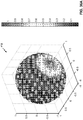
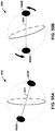
FIGS. 1 and2 are diagrams illustrating spherical harmonic basis functions of various orders and sub-orders. -
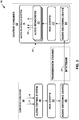
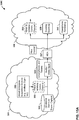
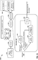
FIG. 3 is a diagram illustrating a system that may perform various aspects of the techniques described in this disclosure. -
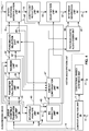
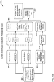
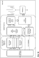
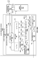
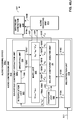
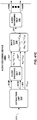
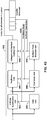
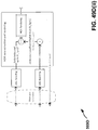
FIG. 4 is a block diagram illustrating, in more detail, one example of the audio encoding device shown in the example ofFIG. 3 that may perform various aspects of the techniques described in this disclosure. -
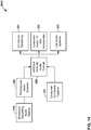
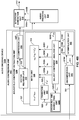
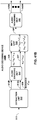
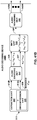
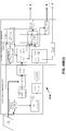
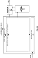
FIG. 5 is a block diagram illustrating the audio decoding device ofFIG. 3 in more detail. -
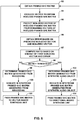
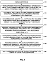
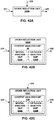
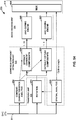
FIG. 6 is a flowchart illustrating exemplary operation of a content analysis unit of an audio encoding device in performing various aspects of the techniques described in this disclosure. -
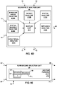
FIG. 7 is a flowchart illustrating exemplary operation of an audio encoding device in performing various aspects of the vector-based synthesis techniques described in this disclosure. -
FIG. 8 is a flow chart illustrating exemplary operation of an audio decoding device in performing various aspects of the techniques described in this disclosure. -
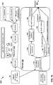
FIGS. 9A-9L are block diagrams illustrating various aspects of the audio encoding device of the example ofFIG. 4 in more detail. -
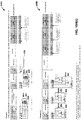
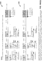
FIGS. 10A-10O(ii) are diagrams illustrating a portion of the bitstream or side channel information that may specify the compressed spatial components in more detail. -
FIGS. 11A-11G are block diagrams illustrating, in more detail, various units of the audio decoding device shown in the example ofFIG. 5 . -
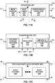
FIG. 12 is a diagram illustrating an example audio ecosystem that may perform various aspects of the techniques described in this disclosure. -
FIG. 13 is a diagram illustrating one example of the audio ecosystem ofFIG. 12 in more detail. -
FIG. 14 is a diagram illustrating one example of the audio ecosystem ofFIG. 12 in more detail. -
FIGS. 15A and15B are diagrams illustrating other examples of the audio ecosystem ofFIG. 12 in more detail. -
FIG. 16 is a diagram illustrating an example audio encoding device that may perform various aspects of the techniques described in this disclosure. -
FIG. 17 is a diagram illustrating one example of the audio encoding device ofFIG. 16 in more detail. -
FIG. 18 is a diagram illustrating an example audio decoding device that may perform various aspects of the techniques described in this disclosure. -
FIG. 19 is a diagram illustrating one example of the audio decoding device ofFIG. 18 in more detail. -
FIGS. 20A-20G are diagrams illustrating example audio acquisition devices that may perform various aspects of the techniques described in this disclosure. -
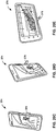
FIGS. 21A-21E are diagrams illustrating example audio playback devices that may perform various aspects of the techniques described in this disclosure. -
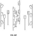
FIGS. 22A-22H are diagrams illustrating example audio playback environments in accordance with one or more techniques described in this disclosure. -
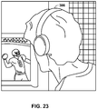
FIG. 23 is a diagram illustrating an example use case where a user may experience a 3D soundfield of a sports game while wearing headphones in accordance with one or more techniques described in this disclosure. -
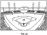
FIG. 24 is a diagram illustrating a sports stadium at which a 3D soundfield may be recorded in accordance with one or more techniques described in this disclosure. -
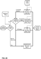
FIG. 25 is a flow diagram illustrating a technique for rendering a 3D soundfield based on a local audio landscape in accordance with one or more techniques described in this disclosure. -
FIG. 26 is a diagram illustrating an example game studio in accordance with one or more techniques described in this disclosure. -
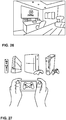
FIG. 27 is a diagram illustrating a plurality game systems which include rendering engines in accordance with one or more techniques described in this disclosure. -
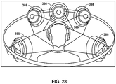
FIG. 28 is a diagram illustrating a speaker configuration that may be simulated by headphones in accordance with one or more techniques described in this disclosure. -
FIG. 29 is a diagram illustrating a plurality of mobile devices which may be used to acquire and/or edit a 3D soundfield in accordance with one or more techniques described in this disclosure. -
FIG. 30 is a diagram illustrating a video frame associated with a 3D soundfield which may be processed in accordance with one or more techniques described in this disclosure. -
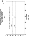
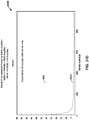
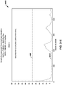
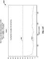
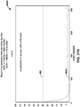
FIGS. 31A-31M are diagrams illustrating graphs showing various simulation results of performing synthetic or recorded categorization of the soundfield in accordance with various aspects of the techniques described in this disclosure. -
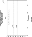
FIG. 32 is a diagram illustrating a graph of singular values from an S matrix decomposed from higher order ambisonic coefficients in accordance with the techniques described in this disclosure. -
FIGS. 33A and 33B are diagrams illustrating respective graphs showing a potential impact reordering has when encoding the vectors describing foreground components of the soundfield in accordance with the techniques described in this disclosure. -
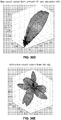
FIGS. 34 and35 are conceptual diagrams illustrating differences between solely energy-based and directionality-based identification of distinct audio objects, in accordance with this disclosure. -
FIGS. 36A-36G are diagrams illustrating projections of at least a portion of decomposed version of spherical harmonic coefficients into the spatial domain so as to perform interpolation in accordance with various aspects of the techniques described in this disclosure. -
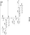
FIG. 37 illustrates a representation of techniques for obtaining a spatio-temporal interpolation as described herein. -
FIG. 38 is a block diagram illustrating artificial US matrices, US1 and US2, for sequential SVD blocks for a multi-dimensional signal according to techniques described herein. -
FIG. 39 is a block diagram illustrating decomposition of subsequent frames of a higher-order ambisonics (HOA) signal using Singular Value Decomposition and smoothing of the spatio-temporal components according to techniques described in this disclosure. -
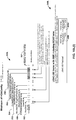
FIGS. 40A-40J are each a block diagram illustrating example audio encoding devices that may perform various aspects of the techniques described in this disclosure to compress spherical harmonic coefficients describing two or three dimensional soundfields. -
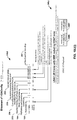
FIG. 41A-41D are block diagrams each illustrating an example audio decoding device that may perform various aspects of the techniques described in this disclosure to decode spherical harmonic coefficients describing two or three dimensional soundfields. -
FIGS. 42A-42C are each block diagrams illustrating the order reduction unit shown in the examples ofFIGS. 40B-40J in more detail. -
FIG. 43 is a diagram illustrating the V compression unit shown inFIG. 40I in more detail. -
FIG. 44 is a diagram illustration exemplary operations performed by the audio encoding device to compensate for quantization error in accordance with various aspects of the techniques described in this disclosure. -
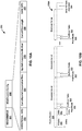
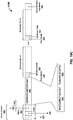
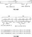
FIGS. 45A and 45B are diagrams illustrating interpolation of sub-frames from portions of two frames in accordance with various aspects of the techniques described in this disclosure. -
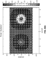
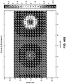
FIGS. 46A-46E are diagrams illustrating a cross section of a projection of one or more vectors of a decomposed version of a plurality of spherical harmonic coefficients having been interpolated in accordance with the techniques described in this disclosure. -
FIG. 47 is a block diagram illustrating, in more detail, the extraction unit of the audio decoding devices shown in the examplesFIGS. 41A-41D . -
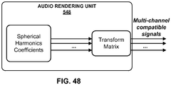
FIG. 48 is a block diagram illustrating the audio rendering unit of the audio decoding device shown in the examples ofFIGS. 41A -41D in more detail. -
FIGS. 49A-49E(ii) are diagrams illustrating respective audio coding systems that may implement various aspects of the techniques described in this disclosure. -
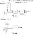
FIGS. 50A and 50B are block diagrams each illustrating one of two different approaches to potentially reduce the order of background content in accordance with the techniques described in this disclosure. -
FIG. 51 is a block diagram illustrating examples of a distinct component compression path of an audio encoding device that may implement various aspects of the techniques described in this disclosure to compress spherical harmonic coefficients. -
FIGS. 52 is a block diagram illustrating another example of an audio decoding device that may implement various aspects of the techniques described in this disclosure to reconstruct or nearly reconstruct spherical harmonic coefficients (SHC). -
FIG. 53 is a block diagram illustrating another example of an audio encoding device that may perform various aspects of the techniques described in this disclosure. -
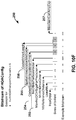
FIG. 54 is a block diagram illustrating, in more detail, an example implementation of the audio encoding device shown in the example ofFIG. 53 . -
FIGS. 55A and 55B are diagrams illustrating an example of performing various aspects of the techniques described in this disclosure to rotate a soundfield. -
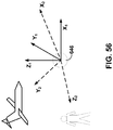
FIG. 56 is a diagram illustrating an example soundfield captured according to a first frame of reference that is then rotated in accordance with the techniques described in this disclosure to express the soundfield in terms of a second frame of reference. -
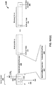
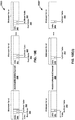
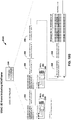
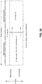
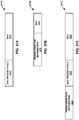
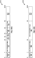
FIGS. 57A-57E are each a diagram illustrating bitstreams formed in accordance with the techniques described in this disclosure. -
FIG. 58 is a flowchart illustrating example operation of the audio encoding device shown in the example ofFIG. 53 in implementing the rotation aspects of the techniques described in this disclosure. -
FIG. 59 is a flowchart illustrating example operation of the audio encoding device shown in the example ofFIG. 53 in performing the transformation aspects of the techniques described in this disclosure. - The evolution of surround sound has made available many output formats for entertainment nowadays. Examples of such consumer surround sound formats are mostly 'channel' based in that they implicitly specify feeds to loudspeakers in certain geometrical coordinates. These include the popular 5.1 format (which includes the following six channels: front left (FL), front right (FR), center or front center, back left or surround left, back right or surround right, and low frequency effects (LFE)), the growing 7.1 format, various formats that includes height speakers such as the 7.1.4 format and the 22.2 format (e.g., for use with the Ultra High Definition Television standard). Non-consumer formats can span any number of speakers (in symmetric and non-symmetric geometries) often termed 'surround arrays'. One example of such an array includes 32 loudspeakers positioned on co-ordinates on the corners of a truncated icosohedron.
- The input to a future MPEG encoder is optionally one of three possible formats: (i) traditional channel-based audio (as discussed above), which is meant to be played through loudspeakers at pre-specified positions; (ii) object-based audio, which involves discrete pulse-code-modulation (PCM) data for single audio objects with associated metadata containing their location coordinates (amongst other information); and (iii) scene-based audio, which involves representing the soundfield using coefficients of spherical harmonic basis functions (also called "spherical harmonic coefficients" or SHC, "Higher Order Ambisonics" or HOA, and "HOA coefficients"). This future MPEG encoder may be described in more detail in a document entitled "Call for Proposals for 3D Audio," by the International Organization for Standardization/ International Electrotechnical Commission (ISO)/(IEC) JTC1/SC29/WG11/N13411, released January 2013 in Geneva, Switzerland, and available at http://mpeg.chiariglione.org/sites/default/files/files/standards/parts/docs/w13411.zip.
- There are various 'surround-sound' channel-based formats in the market. They range, for example, from the 5.1 home theatre system (which has been the most successful in terms of making inroads into living rooms beyond stereo) to the 22.2 system developed by NHK (Nippon Hoso Kyokai or Japan Broadcasting Corporation). Content creators (e.g., Hollywood studios) would like to produce the soundtrack for a movie once, and not spend the efforts to remix it for each speaker configuration. Recently, Standards Developing Organizations have been considering ways in which to provide an encoding into a standardized bitstream and a subsequent decoding that is adaptable and agnostic to the speaker geometry (and number) and acoustic conditions at the location of the playback (involving a renderer).
- To provide such flexibility for content creators, a hierarchical set of elements may be used to represent a soundfield. The hierarchical set of elements may refer to a set of elements in which the elements are ordered such that a basic set of lower-ordered elements provides a full representation of the modeled soundfield. As the set is extended to include higher-order elements, the representation becomes more detailed, increasing resolution.
- One example of a hierarchical set of elements is a set of spherical harmonic coefficients (SHC). The following expression demonstrates a description or representation of a soundfield using SHC:

- This expression shows that the pressure pi at any point {rr, θr, ϕr } of the soundfield, at time t, can be represented uniquely by the SHC,


-
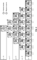
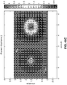
FIG. 1 is a diagram illustrating spherical harmonic basis functions from the zero order (n = 0) to the fourth order (n = 4). As can be seen, for each order, there is an expansion of suborders m which are shown but not explicitly noted in the example ofFIG. 1 for ease of illustration purposes. -
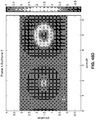
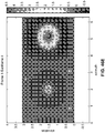
FIG. 2 is another diagram illustrating spherical harmonic basis functions from the zero order (n = 0) to the fourth order (n = 4). InFIG. 2 , the spherical harmonic basis functions are shown in three-dimensional coordinate space with both the order and the suborder shown. - The SHC

- As noted above, the SHC may be derived from a microphone recording using a microphone. Various examples of how SHC may be derived from microphone arrays are described in Poletti, M., "Three-Dimensional Surround Sound Systems Based on Spherical Harmonics," J. Audio Eng. Soc., Vol. 53, No. 11, 2005 November, pp. 1004-1025.
- To illustrate how these SHCs may be derived from an object-based description, consider the following equation. The coefficients


-
FIG. 3 is a diagram illustrating asystem 10 that may perform various aspects of the techniques described in this disclosure. As shown in the example ofFIG. 3 , thesystem 10 includes acontent creator 12 and acontent consumer 14. While described in the context of thecontent creator 12 and thecontent consumer 14, the techniques may be implemented in any context in which SHCs (which may also be referred to as HOA coefficients) or any other hierarchical representation of a soundfield are encoded to form a bitstream representative of the audio data. Moreover, thecontent creator 12 may represent any form of computing device capable of implementing the techniques described in this disclosure, including a handset (or cellular phone), a tablet computer, a smart phone, or a desktop computer to provide a few examples. Likewise, thecontent consumer 14 may represent any form of computing device capable of implementing the techniques described in this disclosure, including a handset (or cellular phone), a tablet computer, a smart phone, a set-top box, or a desktop computer to provide a few examples. - The
content creator 12 may represent a movie studio or other entity that may generate multi-channel audio content for consumption by content consumers, such as thecontent consumer 14. In some examples, thecontent creator 12 may represent an individual user who would like to compressHOA coefficients 11. Often, this content creator generates audio content in conjunction with video content. Thecontent consumer 14 represents an individual that owns or has access to an audio playback system, which may refer to any form of audio playback system capable of rendering SHC for play back as multi-channel audio content. In the example ofFIG. 3 , thecontent consumer 14 includes anaudio playback system 16. - The
content creator 12 includes anaudio editing system 18. Thecontent creator 12 obtainlive recordings 7 in various formats (including directly as HOA coefficients) andaudio objects 9, which thecontent creator 12 may edit usingaudio editing system 18. The content creator may, during the editing process, renderHOA coefficients 11 fromaudio objects 9, listening to the rendered speaker feeds in an attempt to identify various aspects of the soundfield that require further editing. Thecontent creator 12 may then edit HOA coefficients 11 (potentially indirectly through manipulation of different ones of theaudio objects 9 from which the source HOA coefficients may be derived in the manner described above). Thecontent creator 12 may employ theaudio editing system 18 to generate the HOA coefficients 11. Theaudio editing system 18 represents any system capable of editing audio data and outputting this audio data as one or more source spherical harmonic coefficients. - When the editing process is complete, the
content creator 12 may generate abitstream 21 based on the HOA coefficients 11. That is, thecontent creator 12 includes anaudio encoding device 20 that represents a device configured to encode or otherwise compressHOA coefficients 11 in accordance with various aspects of the techniques described in this disclosure to generate thebitstream 21. Theaudio encoding device 20 may generate thebitstream 21 for transmission, as one example, across a transmission channel, which may be a wired or wireless channel, a data storage device, or the like. Thebitstream 21 may represent an encoded version of the HOA coefficients 11 and may include a primary bitstream and another side bitstream, which may be referred to as side channel information. - Although described in more detail below, the
audio encoding device 20 may be configured to encode the HOA coefficients 11 based on a vector-based synthesis or a directional-based synthesis. To determine whether to perform the vector-based synthesis methodology or a directional-based synthesis methodology, theaudio encoding device 20 may determine, based at least in part on the HOA coefficients 11, whether the HOA coefficients 11 were generated via a natural recording of a soundfield (e.g., live recording 7) or produced artificially (i.e., synthetically) from, as one example,audio objects 9, such as a PCM object. When the HOA coefficients 11 were generated form the audio objects 9, theaudio encoding device 20 may encode the HOA coefficients 11 using the directional-based synthesis methodology. When the HOA coefficients 11 were captured live using, for example, an eigenmike, theaudio encoding device 20 may encode the HOA coefficients 11 based on the vector-based synthesis methodology. The above distinction represents one example of where vector-based or directional-based synthesis methodology may be deployed. There may be other cases where either or both may be useful for natural recordings, artificially generated content or a mixture of the two (hybrid content). Furthermore, it is also possible to use both methodologies simultaneously for coding a single time-frame of HOA coefficients. - Assuming for purposes of illustration that the
audio encoding device 20 determines that the HOA coefficients 11 were captured live or otherwise represent live recordings, such as thelive recording 7, theaudio encoding device 20 may be configured to encode the HOA coefficients 11 using a vector-based synthesis methodology involving application of a linear invertible transform (LIT). One example of the linear invertible transform is referred to as a "singular value decomposition" (or "SVD"). In this example, theaudio encoding device 20 may apply SVD to the HOA coefficients 11 to determine a decomposed version of the HOA coefficients 11. Theaudio encoding device 20 may then analyze the decomposed version of the HOA coefficients 11 to identify various parameters, which may facilitate reordering of the decomposed version of the HOA coefficients 11. Theaudio encoding device 20 may then reorder the decomposed version of the HOA coefficients 11 based on the identified parameters, where such reordering, as described in further detail below, may improve coding efficiency given that the transformation may reorder the HOA coefficients across frames of the HOA coefficients (where a frame commonly includes M samples of the HOA coefficients 11 and M is, in some examples, set to 1024). After reordering the decomposed version of the HOA coefficients 11, theaudio encoding device 20 may select those of the decomposed version of the HOA coefficients 11 representative of foreground (or, in other words, distinct, predominant or salient) components of the soundfield. Theaudio encoding device 20 may specify the decomposed version of the HOA coefficients 11 representative of the foreground components as an audio object and associated directional information. - The
audio encoding device 20 may also perform a soundfield analysis with respect to the HOA coefficients 11 in order, at least in part, to identify those of the HOA coefficients 11 representative of one or more background (or, in other words, ambient) components of the soundfield. Theaudio encoding device 20 may perform energy compensation with respect to the background components given that, in some examples, the background components may only include a subset of any given sample of the HOA coefficients 11 (e.g., such as those corresponding to zero and first order spherical basis functions and not those corresponding to second or higher order spherical basis functions). When order-reduction is performed, in other words, theaudio encoding device 20 may augment (e.g., add/subtract energy to/from) the remaining background HOA coefficients of the HOA coefficients 11 to compensate for the change in overall energy that results from performing the order reduction. - The
audio encoding device 20 may next perform a form of psychoacoustic encoding (such as MPEG surround, MPEG-AAC, MPEG-USAC or other known forms of psychoacoustic encoding) with respect to each of the HOA coefficients 11 representative of background components and each of the foreground audio objects. Theaudio encoding device 20 may perform a form of interpolation with respect to the foreground directional information and then perform an order reduction with respect to the interpolated foreground directional information to generate order reduced foreground directional information. Theaudio encoding device 20 may further perform, in some examples, a quantization with respect to the order reduced foreground directional information, outputting coded foreground directional information. In some instances, this quantization may comprise a scalar/entropy quantization. Theaudio encoding device 20 may then form thebitstream 21 to include the encoded background components, the encoded foreground audio objects, and the quantized directional information. Theaudio encoding device 20 may then transmit or otherwise output thebitstream 21 to thecontent consumer 14. - While shown in
FIG. 3 as being directly transmitted to thecontent consumer 14, thecontent creator 12 may output thebitstream 21 to an intermediate device positioned between thecontent creator 12 and thecontent consumer 14. This intermediate device may store thebitstream 21 for later delivery to thecontent consumer 14, which may request this bitstream. The intermediate device may comprise a file server, a web server, a desktop computer, a laptop computer, a tablet computer, a mobile phone, a smart phone, or any other device capable of storing thebitstream 21 for later retrieval by an audio decoder. This intermediate device may reside in a content delivery network capable of streaming the bitstream 21 (and possibly in conjunction with transmitting a corresponding video data bitstream) to subscribers, such as thecontent consumer 14, requesting thebitstream 21. - Alternatively, the
content creator 12 may store thebitstream 21 to a storage medium, such as a compact disc, a digital video disc, a high definition video disc or other storage media, most of which are capable of being read by a computer and therefore may be referred to as computer-readable storage media or non-transitory computer-readable storage media. In this context, the transmission channel may refer to those channels by which content stored to these mediums are transmitted (and may include retail stores and other store-based delivery mechanism). In any event, the techniques of this disclosure should not therefore be limited in this respect to the example ofFIG. 3 . - As further shown in the example of
FIG. 3 , thecontent consumer 14 includes theaudio playback system 16. Theaudio playback system 16 may represent any audio playback system capable of playing back multi-channel audio data. Theaudio playback system 16 may include a number ofdifferent renderers 22. Therenderers 22 may each provide for a different form of rendering, where the different forms of rendering may include one or more of the various ways of performing vector-base amplitude panning (VBAP), and/or one or more of the various ways of performing soundfield synthesis. As used herein, "A and/or B" means "A or B", or both "A and B". - The
audio playback system 16 may further include anaudio decoding device 24. Theaudio decoding device 24 may represent a device configured to decode HOA coefficients 11' from thebitstream 21, where the HOA coefficients 11' may be similar to the HOA coefficients 11 but differ due to lossy operations (e.g., quantization) and/or transmission via the transmission channel. That is, theaudio decoding device 24 may dequantize the foreground directional information specified in thebitstream 21, while also performing psychoacoustic decoding with respect to the foreground audio objects specified in thebitstream 21 and the encoded HOA coefficients representative of background components. Theaudio decoding device 24 may further perform interpolation with respect to the decoded foreground directional information and then determine the HOA coefficients representative of the foreground components based on the decoded foreground audio objects and the interpolated foreground directional information. Theaudio decoding device 24 may then determine the HOA coefficients 11' based on the determined HOA coefficients representative of the foreground components and the decoded HOA coefficients representative of the background components. - The
audio playback system 16 may, after decoding thebitstream 21 to obtain the HOA coefficients 11' and render the HOA coefficients 11' to output loudspeaker feeds 25. The loudspeaker feeds 25 may drive one or more loudspeakers (which are not shown in the example ofFIG. 3 for ease of illustration purposes). - To select the appropriate renderer or, in some instances, generate an appropriate renderer, the
audio playback system 16 may obtainloudspeaker information 13 indicative of a number of loudspeakers and/or a spatial geometry of the loudspeakers. In some instances, theaudio playback system 16 may obtain theloudspeaker information 13 using a reference microphone and driving the loudspeakers in such a manner as to dynamically determine theloudspeaker information 13. In other instances or in conjunction with the dynamic determination of theloudspeaker information 13, theaudio playback system 16 may prompt a user to interface with theaudio playback system 16 and input theloudspeaker information 16. - The
audio playback system 16 may then select one of theaudio renderers 22 based on theloudspeaker information 13. In some instances, theaudio playback system 16 may, when none of theaudio renderers 22 are within some threshold similarity measure (loudspeaker geometry wise) to that specified in theloudspeaker information 13, theaudio playback system 16 may generate the one ofaudio renderers 22 based on theloudspeaker information 13. Theaudio playback system 16 may, in some instances, generate the one ofaudio renderers 22 based on theloudspeaker information 13 without first attempting to select an existing one of theaudio renderers 22. -
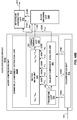
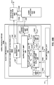
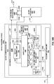
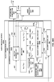
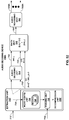
FIG. 4 is a block diagram illustrating, in more detail, one example of theaudio encoding device 20 shown in the example ofFIG. 3 that may perform various aspects of the techniques described in this disclosure. Theaudio encoding device 20 includes acontent analysis unit 26, a vector-basedsynthesis methodology unit 27 and a directional-basedsynthesis methodology unit 28. - The
content analysis unit 26 represents a unit configured to analyze the content of the HOA coefficients 11 to identify whether the HOA coefficients 11 represent content generated from a live recording or an audio object. Thecontent analysis unit 26 may determine whether the HOA coefficients 11 were generated from a recording of an actual soundfield or from an artificial audio object. Thecontent analysis unit 26 may make this determination in various ways. For example, thecontent analysis unit 26 may code (N+1)2-1 channels and predict the last remaining channel (which may be represented as a vector). Thecontent analysis unit 26 may apply scalars to at least some of the (N+1)2-1 channels and add the resulting values to determine the last remaining channel. Furthermore, in this example, thecontent analysis unit 26 may determine an accuracy of the predicted channel. In this example, if the accuracy of the predicted channel is relatively high (e.g., the accuracy exceeds a particular threshold), the HOA coefficients 11 are likely to be generated from a synthetic audio object. In contrast, if the accuracy of the predicted channel is relatively low (e.g., the accuracy is below the particular threshold), the HOA coefficients 11 are more likely to represent a recorded soundfield. For instance, in this example, if a signal-to-noise ratio (SNR) of the predicted channel is over 100 decibels (dbs), the HOA coefficients 11 are more likely to represent a soundfield generated from a synthetic audio object. In contrast, the SNR of a soundfield recorded using an eigen microphone may be 5 to 20 dbs. Thus, there may be an apparent demarcation in SNR ratios between soundfield represented by the HOA coefficients 11 generated from an actual direct recording and from a synthetic audio object. - More specifically, the
content analysis unit 26 may, when determining whether the HOA coefficients 11 representative of a soundfield are generated from a synthetic audio object, obtain a framed of HOA coefficients, which may be ofsize 25 by 1024 for a fourth order representation (i.e., N = 4). After obtaining the framed HOA coefficients (which may also be denoted herein as a framedSHC matrix 11 and subsequent framed SHC matrices may be denoted as framed SHC matrices 27B, 27C, etc.). Thecontent analysis unit 26 may then exclude the first vector of the framedHOA coefficients 11 to generate a reduced framed HOA coefficients. In some examples, this first vector excluded from the framedHOA coefficients 11 may correspond to those of the HOA coefficients 11 associated with the zero-order, zero-sub-order spherical harmonic basis function. - The
content analysis unit 26 may then predicted the first non-zero vector of the reduced framed HOA coefficients from remaining vectors of the reduced framed HOA coefficients. The first non-zero vector may refer to a first vector going from the first-order (and considering each of the order-dependent sub-orders) to the fourth-order (and considering each of the order-dependent sub-orders) that has values other than zero. In some examples, the first non-zero vector of the reduced framed HOA coefficients refers to those ofHOA coefficients 11 associated with the first order, zero-sub-order spherical harmonic basis function. While described with respect to the first non-zero vector, the techniques may predict other vectors of the reduced framed HOA coefficients from the remaining vectors of the reduced framed HOA coefficients. For example, thecontent analysis unit 26 may predict those of the reduced framed HOA coefficients associated with a first-order, first-sub-order spherical harmonic basis function or a first-order, negative-first-order spherical harmonic basis function. As yet other examples, thecontent analysis unit 26 may predict those of the reduced framed HOA coefficients associated with a second-order, zero-order spherical harmonic basis function. - To predict the first non-zero vector, the
content analysis unit 26 may operate in accordance with the following equation:
content analysis unit 26 may obtain an error based on the predicted first non-zero vector and the actual non-zero vector. In some examples, thecontent analysis unit 26 subtracts the predicted first non-zero vector from the actual first non-zero vector to derive the error. Thecontent analysis unit 26 may compute the error as a sum of the absolute value of the differences between each entry in the predicted first non-zero vector and the actual first non-zero vector. - Once the error is obtained, the
content analysis unit 26 may compute a ratio based on an energy of the actual first non-zero vector and the error. Thecontent analysis unit 26 may determine this energy by squaring each entry of the first non-zero vector and adding the squared entries to one another. Thecontent analysis unit 26 may then compare this ratio to a threshold. When the ratio does not exceed the threshold, thecontent analysis unit 26 may determine that the framedHOA coefficients 11 is generated from a recording and indicate in the bitstream that the corresponding coded representation of the HOA coefficients 11 was generated from a recording. When the ratio exceeds the threshold, thecontent analysis unit 26 may determine that the framedHOA coefficients 11 is generated from a synthetic audio object and indicate in the bitstream that the corresponding coded representation of the framedHOA coefficients 11 was generated from a synthetic audio object. - The indication of whether the framed
HOA coefficients 11 was generated from a recording or a synthetic audio object may comprise a single bit for each frame. The single bit may indicate that different encodings were used for each frame effectively toggling between different ways by which to encode the corresponding frame. In some instances, when the framedHOA coefficients 11 were generated from a recording, thecontent analysis unit 26 passes the HOA coefficients 11 to the vector-basedsynthesis unit 27. In some instances, when the framedHOA coefficients 11 were generated from a synthetic audio object, thecontent analysis unit 26 passes the HOA coefficients 11 to the directional-basedsynthesis unit 28. The directional-basedsynthesis unit 28 may represent a unit configured to perform a directional-based synthesis of the HOA coefficients 11 to generate a directional-basedbitstream 21. - In other words, the techniques are based on coding the HOA coefficients using a front-end classifier. The classifier may work as follows:


- The prediction is as follows: predictor vector = sum-over-i [alpha-i x vector-i] (where the sum over I is done over 23 indices, i=1...23)
- Then check the error: actual vector - predictor vector = error.
- If the ratio of the energy of the vector/error is large (I.e. The error is small), then the underlying soundfield (at that frame) is sparse/synthetic. Else, the underlying soundfield is a recorded (using say a mic array) soundfield.
- Depending on the recorded vs. synthetic decision, carry out encoding/decoding (which may refer to bandwidth compression) in different ways. The decision is a 1 bit decision, that is sent over the bitstream for each frame.
- As shown in the example of
FIG. 4 , the vector-basedsynthesis unit 27 may include a linear invertible transform (LIT)unit 30, aparameter calculation unit 32, areorder unit 34, aforeground selection unit 36, anenergy compensation unit 38, a psychoacousticaudio coder unit 40, abitstream generation unit 42, asoundfield analysis unit 44, acoefficient reduction unit 46, a background (BG)selection unit 48, a spatio-temporal interpolation unit 50, and aquantization unit 52. - The linear invertible transform (LIT)
unit 30 receives the HOA coefficients 11 in the form of HOA channels, each channel representative of a block or frame of a coefficient associated with a given order, sub-order of the spherical basis functions (which may be denoted as HOA[k], where k may denote the current frame or block of samples). The matrix ofHOA coefficients 11 may have dimensions D: M x (N+1)2. - That is, the
LIT unit 30 may represent a unit configured to perform a form of analysis referred to as singular value decomposition. While described with respect to SVD, the techniques described in this disclosure may be performed with respect to any similar transformation or decomposition that provides for sets of linearly uncorrelated, energy compacted output. Also, reference to "sets" in this disclosure is generally intended to refer to non-zero sets unless specifically stated to the contrary and is not intended to refer to the classical mathematical definition of sets that includes the so-called "empty set." - An alternative transformation may comprise a principal component analysis, which is often referred to as "PCA." PCA refers to a mathematical procedure that employs an orthogonal transformation to convert a set of observations of possibly correlated variables into a set of linearly uncorrelated variables referred to as principal components. Linearly uncorrelated variables represent variables that do not have a linear statistical relationship (or dependence) to one another. These principal components may be described as having a small degree of statistical correlation to one another. In any event, the number of so-called principal components is less than or equal to the number of original variables. In some examples, the transformation is defined in such a way that the first principal component has the largest possible variance (or, in other words, accounts for as much of the variability in the data as possible), and each succeeding component in turn has the highest variance possible under the constraint that this successive component be orthogonal to (which may be restated as uncorrelated with) the preceding components. PCA may perform a form of order-reduction, which in terms of the HOA coefficients 11 may result in the compression of the HOA coefficients 11. Depending on the context, PCA may be referred to by a number of different names, such as discrete Karhunen-Loeve transform, the Hotelling transform, proper orthogonal decomposition (POD), and eigenvalue decomposition (EVD) to name a few examples. Properties of such operations that are conducive to the underlying goal of compressing audio data are 'energy compaction' and 'decorrelation' of the multichannel audio data.
- In any event, the
LIT unit 30 performs a singular value decomposition (which, again, may be referred to as "SVD") to transform the HOA coefficients 11 into two or more sets of transformed HOA coefficients. These "sets" of transformed HOA coefficients may include vectors of transformed HOA coefficients. In the example ofFIG. 4 , theLIT unit 30 may perform the SVD with respect to the HOA coefficients 11 to generate a so-called V matrix, an S matrix, and a U matrix. SVD, in linear algebra, may represent a factorization of a y-by-z real or complex matrix X (where X may represent multi-channel audio data, such as the HOA coefficients 11) in the following form:
- While described in this disclosure as being applied to multi-channel audio data comprising
HOA coefficients 11, the techniques may be applied to any form of multi-channel audio data. In this way, theaudio encoding device 20 may perform a singular value decomposition with respect to multi-channel audio data representative of at least a portion of soundfield to generate a U matrix representative of left-singular vectors of the multi-channel audio data, an S matrix representative of singular values of the multi-channel audio data and a V matrix representative of right-singular vectors of the multi-channel audio data, and representing the multi-channel audio data as a function of at least a portion of one or more of the U matrix, the S matrix and the V matrix. - In some examples, the V* matrix in the SVD mathematical expression referenced above is denoted as the conjugate transpose of the V matrix to reflect that SVD may be applied to matrices comprising complex numbers. When applied to matrices comprising only real-numbers, the complex conjugate of the V matrix (or, in other words, the V* matrix) may be considered to be the transpose of the V matrix. Below it is assumed, for ease of illustration purposes, that the HOA coefficients 11 comprise real-numbers with the result that the V matrix is output through SVD rather than the V* matrix. Moreover, while denoted as the V matrix in this disclosure, reference to the V matrix should be understood to refer to the transpose of the V matrix where appropriate. While assumed to be the V matrix, the techniques may be applied in a similar fashion to
HOA coefficients 11 having complex coefficients, where the output of the SVD is the V* matrix. Accordingly, the techniques should not be limited in this respect to only provide for application of SVD to generate a V matrix, but may include application of SVD toHOA coefficients 11 having complex components to generate a V* matrix. - In any event, the
LIT unit 30 may perform a block-wise form of SVD with respect to each block (which may refer to a frame) of higher-order ambisonics (HOA) audio data (where this ambisonics audio data includes blocks or samples of the HOA coefficients 11 or any other form of multi-channel audio data). As noted above, a variable M may be used to denote the length of an audio frame in samples. For example, when an audio frame includes 1024 audio samples, M equals 1024. Although described with respect to this typical value for M, the techniques of this disclosure should not be limited to this typical value for M. TheLIT unit 30 may therefore perform a block-wise SVD with respect to a block the HOA coefficients 11 having M-by-(N+1)2 HOA coefficients, where N, again, denotes the order of the HOA audio data. TheLIT unit 30 may generate, through performing this SVD, a V matrix, an S matrix, and a U matrix, where each of matrixes may represent the respective V, S and U matrixes described above. In this way, the linearinvertible transform unit 30 may perform SVD with respect to the HOA coefficients 11 to output US[k] vectors 33 (which may represent a combined version of the S vectors and the U vectors) having dimensions D: M x (N+1)2, and V[k]vectors 35 having dimensions D: (N+1)2 x (N+1)2. Individual vector elements in the US[k] matrix may also be termed XPS (k) while individual vectors of the V[k] matrix may also be termed v(k). - An analysis of the U, S and V matrices may reveal that these matrices carry or represent spatial and temporal characteristics of the underlying soundfield represented above by X. Each of the N vectors in U (of length M samples) may represent normalized separated audio signals as a function of time (for the time period represented by M samples), that are orthogonal to each other and that have been decoupled from any spatial characteristics (which may also be referred to as directional information). The spatial characteristics, representing spatial shape and position (r, theta, phi) width may instead be represented by individual i th vectors , v (i)(k), in the V matrix (each of length (N+1)2). Both the vectors in the U matrix and the V matrix are normalized such that their root-mean-square energies are equal to unity. The energy of the audio signals in U are thus represented by the diagonal elements in S. Multiplying U and S to form US[k] (with individual vector elements XPS (k)), thus represent the audio signal with true energies. The ability of the SVD decomposition to decouple the audio time-signals (in U), their energies (in S) and their spatial characteristics (in V) may support various aspects of the techniques described in this disclosure. Further, this model of synthesizing the underlying HOA[k] coefficients, X, by a vector multiplication of US[k] and V[k] gives rise the term "vector based synthesis methodology," which is used throughout this document.
- Although described as being performed directly with respect to the HOA coefficients 11, the
LIT unit 30 may apply the linear invertible transform to derivatives of the HOA coefficients 11. For example, theLIT unit 30 may apply SVD with respect to a power spectral density matrix derived from the HOA coefficients 11. The power spectral density matrix may be denoted as PSD and obtained through matrix multiplication of the transpose of the hoaFrame to the hoaFrame, as outlined in the pseudo-code that follows below. The hoaFrame notation refers to a frame of the HOA coefficients 11. - The
LIT unit 30 may, after applying the SVD (svd) to the PSD, may obtain an S[k]2 matrix (S_squared) and a V[k] matrix. The S[k]2 matrix may denote a squared S[k] matrix, whereupon theLIT unit 30 may apply a square root operation to the S[k]2 matrix to obtain the S[k] matrix. TheLIT unit 30 may, in some instances, perform quantization with respect to the V[k] matrix to obtain a quantized V[k] matrix (which may be denoted as V[k]' matrix). TheLIT unit 30 may obtain the U[k] matrix by first multiplying the S[k] matrix by the quantized V[k]' matrix to obtain an SV [k]' matrix. TheLIT unit 30 may next obtain the pseudo-inverse (pinv) of the SV[k]' matrix and then multiply the HOA coefficients 11 by the pseudo-inverse of the SV[k]' matrix to obtain the U[k] matrix. The foregoing may be represented by the following pseud-code:


- By performing SVD with respect to the power spectral density (PSD) of the HOA coefficients rather than the coefficients themselves, the
LIT unit 30 may potentially reduce the computational complexity of performing the SVD in terms of one or more of processor cycles and storage space, while achieving the same source audio encoding efficiency as if the SVD were applied directly to the HOA coefficients. That is, the above described PSD-type SVD may be potentially less computational demanding because the SVD is done on an F*F matrix (with F the number of HOA coefficients). Compared to a M * F matrix with M is the framelength, i.e., 1024 or more samples. The complexity of an SVD may now, through application to the PSD rather than the HOA coefficients 11, be around O(L^3) compared to O(M*L^2) when applied to the HOA coefficients 11 (where O(*) denotes the big-O notation of computation complexity common to the computer-science arts). - The
parameter calculation unit 32 represents unit configured to calculate various parameters, such as a correlation parameter (R), directional properties parameters (θ, ϕ, r), and an energy property (e). Each of these parameters for the current frame may be denoted as R[k], θ[k], ϕ[k], r[k] and e[k]. Theparameter calculation unit 32 may perform an energy analysis and/or correlation (or so-called cross-correlation) with respect to the US[k]vectors 33 to identify these parameters. Theparameter calculation unit 32 may also determine these parameters for the previous frame, where the previous frame parameters may be denoted R[k-1], θ[k-1], ϕ[k-1], r[k-1] and e[k-1], based on the previous frame of US[k-1] vector and V[k-1] vectors. Theparameter calculation unit 32 may output thecurrent parameters 37 and theprevious parameters 39 to reorderunit 34. - That is, the
parameter calculation unit 32 may perform an energy analysis with respect to each of the L first US[k]vectors 33 corresponding to a first time and each of the second US[k-1]vectors 33 corresponding to a second time, computing a root mean squared energy for at least a portion of (but often the entire) first audio frame and a portion of (but often the entire) second audio frame and thereby generate 2L energies, one for each of the L first US[k]vectors 33 of the first audio frame and one for each of the second US[k-1]vectors 33 of the second audio frame. - In other examples, the
parameter calculation unit 32 may perform a cross-correlation between some portion of (if not the entire) set of samples for each of the first US[k]vectors 33 and each of the second US[k-1]vectors 33. Cross-correlation may refer to cross-correlation as understood in the signal processing arts. In other words, cross-correlation may refer to a measure of similarity between two waveforms (which in this case is defined as a discrete set of M samples) as a function of a time-lag applied to one of them. In some examples, to perform cross-correlation, theparameter calculation unit 32 compares the last L samples of each the first US[k]vectors 27, turn-wise, to the first L samples of each of the remaining ones of the second US[k-1]vectors 33 to determine a correlation parameter. As used herein, a "turn-wise" operation refers to an element by element operation made with respect to a first set of elements and a second set of elements, where the operation draws one element from each of the first and second sets of elements "in-turn" according to an ordering of the sets. - The
parameter calculation unit 32 may also analyze the V[k] and/or V[k-1]vectors 35 to determine directional property parameters. These directional property parameters may provide an indication of movement and location of the audio object represented by the corresponding US[k] and/or US[k-1]vectors 33. Theparameter calculation unit 32 may provide any combination of the foregoing current parameters 37 (determined with respect to the US[k]vectors 33 and/or the V[k] vectors 35) and any combination of the previous parameters 39 (determined with respect to the US[k-1]vectors 33 and/or the V[k-1] vectors 35) to thereorder unit 34. - The SVD decomposition does not guarantee that the audio signal/object represented by the p-th vector in US[k-1]
vectors 33, which may be denoted as the US[k-1][p] vector (or, alternatively, as XPS (p)(k - 1)), will be the same audio signal /object (progressed in time) represented by the p-th vector in the US[k]vectors 33, which may also be denoted as US[k][p] vectors 33 (or, alternatively as XPS (p)(k)). The parameters calculated by theparameter calculation unit 32 may be used by thereorder unit 34 to re-order the audio objects to represent their natural evaluation or continuity over time. - That is, the
reorder unit 34 may then compare each of theparameters 37 from the first US[k]vectors 33 turn-wise against each of theparameters 39 for the second US[k-1]vectors 33. Thereorder unit 34 may reorder (using, as one example, a Hungarian algorithm) the various vectors within the US[k]matrix 33 and the V[k]matrix 35 based on thecurrent parameters 37 and theprevious parameters 39 to output a reordered US[k]matrix 33' (which may be denoted mathematically asUS [k]) and a reordered V[k]matrix 35' (which may be denoted mathematically asV [k]) to a foreground sound (or predominant sound - PS) selection unit 36 ("foreground selection unit 36") and anenergy compensation unit 38. - In other words, the
reorder unit 34 may represent a unit configured to reorder the vectors within the US[k]matrix 33 to generate reordered US[k]matrix 33'. Thereorder unit 34 may reorder the US[k]matrix 33 because the order of the US[k] vectors 33 (where, again, each vector of the US[k]vectors 33, which again may alternatively be denoted as XPS (p)(k), may represent one or more distinct (or, in other words, predominant) mono-audio object present in the soundfield) may vary from portions of the audio data. That is, given that theaudio encoding device 12, in some examples, operates on these portions of the audio data generally referred to as audio frames, the position of vectors corresponding to these distinct mono-audio objects as represented in the US[k]matrix 33 as derived, may vary from audio frame-to-audio frame due to application of SVD to the frames and the varying saliency of each audio object form frame-to-frame. - Passing vectors within the US[k]
matrix 33 directly to the psychoacousticaudio coder unit 40 without reordering the vectors within the US[k]matrix 33 from audio frame-to audio frame may reduce the extent of the compression achievable for some compression schemes, such as legacy compression schemes that perform better when mono-audio objects are continuous (channel-wise, which is defined in this example by the positional order of the vectors within the US[k]matrix 33 relative to one another) across audio frames. Moreover, when not reordered, the encoding of the vectors within the US[k]matrix 33 may reduce the quality of the audio data when decoded. For example, AAC encoders, which may be represented in the example ofFIG. 3 by the psychoacousticaudio coder unit 40, may more efficiently compress the reordered one or more vectors within the US[k]matrix 33' from frame-to-frame in comparison to the compression achieved when directly encoding the vectors within the US[k]matrix 33 from frame-to-frame. While described above with respect to AAC encoders, the techniques may be performed with respect to any encoder that provides better compression when mono-audio objects are specified across frames in a specific order or position (channel-wise). - Various aspects of the techniques may, in this way, enable
audio encoding device 12 to reorder one or more vectors (e.g., the vectors within the US[k]matrix 33 to generate reordered one or more vectors within the reordered US[k]matrix 33' and thereby facilitate compression of the vectors within the US[k]matrix 33 by a legacy audio encoder, such as the psychoacoustic audio coder unit 40). - For example, the
reorder unit 34 may reorder one or more vectors within the US[k]matrix 33 from a first audio frame subsequent in time to the second frame to which one or more second vectors within the US[k-1]matrix 33 correspond based on thecurrent parameters 37 andprevious parameters 39. While described in the context of a first audio frame being subsequent in time to the second audio frame, the first audio frame may precede in time the second audio frame. Accordingly, the techniques should not be limited to the example described in this disclosure. - To illustrate consider the following Table 1 where each of the p vectors within the US[k]
matrix 33 is denoted as US[k][p], where k denotes whether the corresponding vector is from the k-th frame or the previous (k-1)-th frame and p denotes the row of the vector relative to vectors of the same audio frame (where the US[k] matrix has (N+1)2 such vectors). As noted above, assuming N is determined to be one, p may denote vectors one (1) through (4).Table 1 Energy Under Consideration Compared To US[k-1][1] US[k][1], US[k][2], US[k][3], US[k][4] US[k-1][2] US[k][1], US[k][2], US[k][3], US[k][4] US[k-1][3] US[k][1], US[k][2], US[k][3], US[k][4] US[k-1][4] US[k][1], US[k][2], US[k][3], US[k][4] - In the above Table 1, the
reorder unit 34 compares the energy computed for US[k-1][1] to the energy computed for each of US[k][1], US[k][2], US[k][3], US[k][4], the energy computed for US[k-1][2] to the energy computed for each of US[k][1], US[k][2], US[k][3], US[k][4], etc. Thereorder unit 34 may then discard one or more of the second US[k-1]vectors 33 of the second preceding audio frame (time-wise). To illustrate, consider the following Table 2 showing the remaining second US[k-1] vectors 33:Table 2 Vector Under Consideration Remaining Under Consideration US[k-1][1] US[k][1], US[k][2] US[k-1][2] US[k][1], US[k][2] US[k-1][3] US[k][3], US[k][4] US[k-1][4] US[k][3], US[k][4] - In the above Table 2, the
reorder unit 34 may determine, based on the energy comparison that the energy computed for US[k-1][1] is similar to the energy computed for each of US[k][1] and US[k][2], the energy computed for US[k-1][2] is similar to the energy computed for each of US[k][1] and US[k][2], the energy computed for US[k-1][3] is similar to the energy computed for each of US[k][3] and US[k][4], and the energy computed for US[k-1][4] is similar to the energy computed for each of US[k][3] and US[k][4]. In some examples, thereorder unit 34 may perform further energy analysis to identify a similarity between each of the first vectors of the US[k]matrix 33 and each of the second vectors of the US[k-1]matrix 33. - In other examples, the
reorder unit 32 may reorder the vectors based on thecurrent parameters 37 and theprevious parameters 39 relating to cross-correlation. In these examples, referring back to Table 2 above, thereorder unit 34 may determine the following exemplary correlation expressed in Table 3 based on these cross-correlation parameters:Table 3 Vector Under Consideration Correlates To US[k-1][1] US[k][2] US[k-1][2] US[k][1] US[k-1][3] US[k][3] US[k-1][4] US[k][4] - From the above Table 3, the
reorder unit 34 determines, as one example, that US[k-1][1] vector correlates to the differently positioned US[k][2] vector, the US[k-1][2] vector correlates to the differently positioned US[k][1] vector, the US[k-1][3] vector correlates to the similarly positioned US[k][3] vector, and the US[k-1][4] vector correlates to the similarly positioned US[k][4] vector. In other words, thereorder unit 34 determines what may be referred to as reorder information describing how to reorder the first vectors of the US[k]matrix 33 such that the US[k][2] vector is repositioned in the first row of the first vectors of the US[k]matrix 33 and the US[k][1] vector is repositioned in the second row of the first US[k]vectors 33. Thereorder unit 34 may then reorder the first vectors of the US[k]matrix 33 based on this reorder information to generate the reordered US[k]matrix 33'. - Additionally, the
reorder unit 34 may, although not shown in the example ofFIG. 4 , provide this reorder information to thebitstream generation device 42, which may generate thebitstream 21 to include this reorder information so that the audio decoding device, such as theaudio decoding device 24 shown in the example ofFIGS. 3 and5 , may determine how to reorder the reordered vectors of the US[k]matrix 33' so as to recover the vectors of the US[k]matrix 33. - While described above as performing a two-step process involving an analysis based first an energy-specific parameters and then cross-correlation parameters, the
reorder unit 32 may only perform this analysis only with respect to energy parameters to determine the reorder information, perform this analysis only with respect to cross-correlation parameters to determine the reorder information, or perform the analysis with respect to both the energy parameters and the cross-correlation parameters in the manner described above. Additionally, the techniques may employ other types of processes for determining correlation that do not involve performing one or both of an energy comparison and/or a cross-correlation. Accordingly, the techniques should not be limited in this respect to the examples set forth above. Moreover, other parameters obtained from the parameter calculation unit 32 (such as the spatial position parameters derived from the V vectors or correlation of the vectors in the V[k] and V[k-1]) can also be used (either concurrently/jointly or sequentially) with energy and cross-correlation parameters obtained from US[k] and US[k-1] to determine the correct ordering of the vectors in US. - As one example of using correlation of the vectors in the V matrix, the
parameter calculation unit 34 may determine that the vectors of the V[k]matrix 35 are correlated as specified in the following Table 4:Table 4 Vector Under Consideration Correlates To V[k-1][1] V[k][2] V[k-1][2] V[k][1] V[k-1][3] V[k][3] V[k-1][4] V[k][4] - From the above Table 4, the
reorder unit 34 determines, as one example, that V[k-1][1] vector correlates to the differently positioned V[k][2] vector, the V[k-1][2] vector correlates to the differently positioned V[k][1] vector, the V[k-1][3] vector correlates to the similarly positioned V[k][3] vector, and the V[k-1][4] vector correlates to the similarly positioned V[k][4] vector. Thereorder unit 34 may output the reordered version of the vectors of the V[k]matrix 35 as a reordered V[k]matrix 35'. - In some examples, the same re-ordering that is applied to the vectors in the US matrix is also applied to the vectors in the V matrix. In other words, any analysis used in reordering the V vectors may be used in conjunction with any analysis used to reorder the US vectors. To illustrate an example in which the reorder information is not solely determined with respect to the energy parameters and/or the cross-correlation parameters with respect to the US[k]
vectors 35, thereorder unit 34 may also perform this analysis with respect to the V[k]vectors 35 based on the cross-correlation parameters and the energy parameters in a manner similar to that described above with respect to the V[k]vectors 35. Moreover, while the US[k]vectors 33 do not have any directional properties, the V[k]vectors 35 may provide information relating to the directionality of the corresponding US[k]vectors 33. In this sense, thereorder unit 34 may identify correlations between V[k]vectors 35 and V[k-1]vectors 35 based on an analysis of corresponding directional properties parameters. That is, in some examples, audio object move within a soundfield in a continuous manner when moving or that stays in a relatively stable location. As such, thereorder unit 34 may identify those vectors of the V[k]matrix 35 and the V[k-1]matrix 35 that exhibit some known physically realistic motion or that stay stationary within the soundfield as correlated, reordering the US[k]vectors 33 and the V[k]vectors 35 based on this directional properties correlation. In any event, thereorder unit 34 may output the reordered US[k]vectors 33' and the reordered V[k]vectors 35' to theforeground selection unit 36. - Additionally, the techniques may employ other types of processes for determining correct order that do not involve performing one or both of an energy comparison and/or a cross-correlation. Accordingly, the techniques should not be limited in this respect to the examples set forth above.
- Although described above as reordering the vectors of the V matrix to mirror the reordering of the vectors of the US matrix, in certain instances, the V vectors may be reordered differently than the US vectors, where separate syntax elements may be generated to indicate the reordering of the US vectors and the reordering of the V vectors. In some instances, the V vectors may not be reordered and only the US vectors may be reordered given that the V vectors may not be psychoacoustically encoded.
- An embodiment where the re-ordering of the vectors of the V matrix and the vectors of US matrix are different are when the intention is to swap audio objects in space - i.e. move them away from the original recorded position (when the underlying soundfield was a natural recording) or the artistically intended position (when the underlying soundfield is an artificial mix of objects). As an example, suppose that there are two audio sources A and B, A may be the sound of a cat "meow" emanating from the "left" part of soundfield and B may be the sound of a dog "woof" emanating from the "right" part of the soundfield. When the re-ordering of the V and US are different, the position of the two sound sources is swapped. After swapping A (the "meow") emanates from the right part of the soundfield, and B ("the woof") emanates from the left part of the soundfield.
- The
soundfield analysis unit 44 may represent a unit configured to perform a soundfield analysis with respect to the HOA coefficients 11 so as to potentially achieve atarget bitrate 41. Thesoundfield analysis unit 44 may, based on this analysis and/or on a receivedtarget bitrate 41, determine the total number of psychoacoustic coder instantiations (which may be a function of the total number of ambient or background channels (BGTOT) and the number of foreground channels or, in other words, predominant channels. The total number of psychoacoustic coder instantiations can be denoted as numHOATransportChannels. Thesoundfield analysis unit 44 may also determine, again to potentially achieve thetarget bitrate 41, the total number of foreground channels (nFG) 45, the minimum order of the background (or, in other words, ambient) soundfield (NBG or, alternatively, MinAmbHoaOrder), the corresponding number of actual channels representative of the minimum order of background soundfield (nBGa = (MinAmbHoaOrder+1)2), and indices (i) of additional BG HOA channels to send (which may collectively be denoted asbackground channel information 43 in the example ofFIG. 4 ). Thebackground channel information 42 may also be referred to asambient channel information 43. Each of the channels that remains from numHOATransportChannels - nBGa, may either be an "additional background/ambient channel", an "active vector based predominant channel", an "active directional based predominant signal" or "completely inactive". In one embodiment, these channel types may be indicated (as a "ChannelType") syntax element by two bits (e.g. 00:additional background channel; 01:vector based predominant signal; 10: inactive signal; 11: directional based signal). The total number of background or ambient signals, nBGa, may be given by (MinAmbHoaOrder +1)2 + the number of times the index 00 (in the above example) appears as a channel type in the bitstream for that frame. - In any event, the
soundfield analysis unit 44 may select the number of background (or, in other words, ambient) channels and the number of foreground (or, in other words, predominant) channels based on thetarget bitrate 41, selecting more background and/or foreground channels when thetarget bitrate 41 is relatively higher (e.g., when thetarget bitrate 41 equals or is greater than 512 Kbps). In one embodiment, the numHOATransportChannels may be set to 8 while the MinAmbHoaOrder may be set to 1 in the header section of the bitstream (which is described in more detail with respect toFIGS. 10-10O(ii) ). In this scenario, at every frame, four channels may be dedicated to represent the background or ambient portion of the soundfield while the other 4 channels can, on a frame-by-frame basis vary on the type of channel - e.g., either used as an additional background/ambient channel or a foreground/predominant channel. The foreground/predominant signals can be one of either vector based or directional based signals, as described above. - In some instances, the total number of vector based predominant signals for a frame, may be given by the number of times the ChannelType index is 01, in the bitstream of that frame, in the above example. In the above embodiment, for every additional background/ambient channel (e.g., corresponding to a ChannelType of 00), a corresponding information of which of the possible HOA coefficients (beyond the first four) may be represented in that channel. This information, for fourth order HOA content, may be an index to indicate between 5-25 (the first four 1-4 may be sent all the time when minAmbHoaOrder is set to 1, hence only need to indicate one between 5-25). This information could thus be sent using a 5 bits syntax element (for 4th order content), which may be denoted as "CodedAmbCoeffIdx."
- In a second embodiment, all of the foreground/predominant signals are vector based signals. In this second embodiment, the total number of foreground/predominant signals may be given by nFG = numHOATransportChannels - [(MinAmbHoaOrder +1)2 + the number of times the index 00].
- The
soundfield analysis unit 44 outputs thebackground channel information 43 and the HOA coefficients 11 to the background (BG)selection unit 46, thebackground channel information 43 tocoefficient reduction unit 46 and thebitstream generation unit 42, and thenFG 45 to aforeground selection unit 36. - In some examples, the
soundfield analysis unit 44 may select, based on an analysis of the vectors of the US[k]matrix 33 and thetarget bitrate 41, a variable nFG number of these components having the greatest value. In other words, thesoundfield analysis unit 44 may determine a value for a variable A (which may be similar or substantially similar to NBG), which separates two subspaces, by analyzing the slope of the curve created by the descending diagonal values of the vectors of the S[k]matrix 33, where the large singular values represent foreground or distinct sounds and the low singular values represent background components of the soundfield. That is, the variable A may segment the overall soundfield into a foreground subspace and a background subspace. - In some examples, the
soundfield analysis unit 44 may use a first and a second derivative of the singular value curve. Thesoundfield analysis unit 44 may also limit the value for the variable A to be between one and five. As another example, thesoundfield analysis unit 44 may limit the value of the variable A to be between one and (N+1)2. Alternatively, thesoundfield analysis unit 44 may pre-define the value for the variable A, such as to a value of four. In any event, based on the value of A, thesoundfield analysis unit 44 determines the total number of foreground channels (nFG) 45, the order of the background soundfield (NBG) and the number (nBGa) and the indices (i) of additional BG HOA channels to send. - Furthermore, the
soundfield analysis unit 44 may determine the energy of the vectors in the V[k]matrix 35 on a per vector basis. Thesoundfield analysis unit 44 may determine the energy for each of the vectors in the V[k]matrix 35 and identify those having a high energy as foreground components. - Moreover, the
soundfield analysis unit 44 may perform various other analyses with respect to the HOA coefficients 11, including a spatial energy analysis, a spatial masking analysis, a diffusion analysis or other forms of auditory analyses. Thesoundfield analysis unit 44 may perform the spatial energy analysis through transformation of the HOA coefficients 11 into the spatial domain and identifying areas of high energy representative of directional components of the soundfield that should be preserved. Thesoundfield analysis unit 44 may perform the perceptual spatial masking analysis in a manner similar to that of the spatial energy analysis, except that thesoundfield analysis unit 44 may identify spatial areas that are masked by spatially proximate higher energy sounds. Thesoundfield analysis unit 44 may then, based on perceptually masked areas, identify fewer foreground components in some instances. Thesoundfield analysis unit 44 may further perform a diffusion analysis with respect to the HOA coefficients 11 to identify areas of diffuse energy that may represent background components of the soundfield. - The
soundfield analysis unit 44 may also represent a unit configured to determine saliency, distinctness or predominance of audio data representing a soundfield, using directionality-based information associated with the audio data. While energy-based determinations may improve rendering of a soundfield decomposed by SVD to identify distinct audio components of the soundfield, energy-based determinations may also cause a device to erroneously identify background audio components as distinct audio components, in cases where the background audio components exhibit a high energy level. That is, a solely energy-based separation of distinct and background audio components may not be robust, as energetic (e.g., louder) background audio components may be incorrectly identified as being distinct audio components. To more robustly distinguish between distinct and background audio components of the soundfield, various aspects of the techniques described in this disclosure may enable thesoundfield analysis unit 44 to perform a directionality-based analysis of the HOA coefficients 11 to separate foreground and ambient audio components from decomposed versions of the HOA coefficients 11. - In this respect, the
soundfield analysis unit 44 may represent a unit configured or otherwise operable to identify distinct (or foreground) elements from background elements included in one or more of the vectors in the US[k]matrix 33 and the vectors in the V[k]matrix 35. According to some SVD-based techniques, the most energetic components (e.g., the first few vectors of one or more of the US[k]matrix 33 and the V[k]matrix 35 or vectors derived therefrom) may be treated as distinct components. However, the most energetic components (which are represented by vectors) of one or more of the vectors in the US[k]matrix 33 and the vectors in the V[k]matrix 35 may not, in all scenarios, represent the components/signals that are the most directional. - The
soundfield analysis unit 44 may implement one or more aspects of the techniques described herein to identify foreground/direct/predominant elements based on the directionality of the vectors of one or more of the vectors in the US[k]matrix 33 and the vectors in the V[k]matrix 35 or vectors derived therefrom. In some examples, thesoundfield analysis unit 44 may identify or select as distinct audio components (where the components may also be referred to as "objects"), one or more vectors based on both energy and directionality of the vectors. For instance, thesoundfield analysis unit 44 may identify those vectors of one or more of the vectors in the US[k]matrix 33 and the vectors in the V[k] matrix 35 (or vectors derived therefrom) that display both high energy and high directionality (e.g., represented as a directionality quotient) as distinct audio components. As a result, if thesoundfield analysis unit 44 determines that a particular vector is relatively less directional when compared to other vectors of one or more of the vectors in the US[k]matrix 33 and the vectors in the V[k] matrix 35 (or vectors derived therefrom), then regardless of the energy level associated with the particular vector, thesoundfield analysis unit 44 may determine that the particular vector represents background (or ambient) audio components of the soundfield represented by the HOA coefficients 11. - In some examples, the
soundfield analysis unit 44 may identify distinct audio objects (which, as noted above, may also be referred to as "components") based on directionality, by performing the following operations. Thesoundfield analysis unit 44 may multiply (e.g., using one or more matrix multiplication processes) vectors in the S[k] matrix (which may be derived from the US[k]vectors 33 or, although not shown in the example ofFIG. 4 separately output by the LIT unit 30) by the vectors in the V[k]matrix 35. By multiplying the V[k]matrix 35 and the S[k] vectors, thesoundfield analysis unit 44 may obtain VS[k] matrix. Additionally, thesoundfield analysis unit 44 may square (i.e., exponentiate by a power of two) at least some of the entries of each of the vectors in the VS[k] matrix. In some instances, thesoundfield analysis unit 44 may sum those squared entries of each vector that are associated with an order greater than 1. - As one example, if each vector of the VS[k] matrix, which includes 25 entries, the
soundfield analysis unit 44 may, with respect to each vector, square the entries of each vector beginning at the fifth entry and ending at the twenty-fifth entry, summing the squared entries to determine a directionality quotient (or a directionality indicator). Each summing operation may result in a directionality quotient for a corresponding vector. In this example, thesoundfield analysis unit 44 may determine that those entries of each row that are associated with an order less than or equal to 1, namely, the first through fourth entries, are more generally directed to the amount of energy and less to the directionality of those entries. That is, the lower order ambisonics associated with an order of zero or one correspond to spherical basis functions that, as illustrated inFIG. 1 andFIG. 2 , do not provide much in terms of the direction of the pressure wave, but rather provide some volume (which is representative of energy). - The operations described in the example above may also be expressed according to the following pseudo-code. The pseudo-code below includes annotations, in the form of comment statements that are included within consecutive instances of the character strings "/*" and "*/" (without quotes).


- In other words, according to the above pseudo-code, the
soundfield analysis unit 44 may select entries of each vector of the VS[k] matrix decomposed from those of the HOA coefficients 11 corresponding to a spherical basis function having an order greater than one. Thesoundfield analysis unit 44 may then square these entries for each vector of the VS[k] matrix, summing the squared entries to identify, compute or otherwise determine a directionality metric or quotient for each vector of the VS[k] matrix. Next, thesoundfield analysis unit 44 may sort the vectors of the VS[k] matrix based on the respective directionality metrics of each of the vectors. Thesoundfield analysis unit 44 may sort these vectors in a descending order of directionality metrics, such that those vectors with the highest corresponding directionality are first and those vectors with the lowest corresponding directionality are last. Thesoundfield analysis unit 44 may then select the a non-zero subset of the vectors having the highest relative directionality metric. - The
soundfield analysis unit 44 may perform any combination of the foregoing analyses to determine the total number of psychoacoustic coder instantiations (which may be a function of the total number of ambient or background channels (BGTOT) and the number of foreground channels. Thesoundfield analysis unit 44 may, based on any combination of the foregoing analyses, determine the total number of foreground channels (nFG) 45, the order of the background soundfield (NBG) and the number (nBGa) and indices (i) of additional BG HOA channels to send (which may collectively be denoted asbackground channel information 43 in the example ofFIG. 4 ). - In some examples, the
soundfield analysis unit 44 may perform this analysis every M-samples, which may be restated as on a frame-by-frame basis. In this respect, the value for A may vary from frame to frame. An instance of a bitstream where the decision is made every M-samples is shown inFIGS. 10-10O(ii) . In other examples, thesoundfield analysis unit 44 may perform this analysis more than once per frame, analyzing two or more portions of the frame. Accordingly, the techniques should not be limited in this respect to the examples described in this disclosure. - The
background selection unit 48 may represent a unit configured to determine background orambient HOA coefficients 47 based on the background channel information (e.g., the background soundfield (NBG) and the number (nBGa) and the indices (i) of additional BG HOA channels to send). For example, when NBG equals one, thebackground selection unit 48 may select the HOA coefficients 11 for each sample of the audio frame having an order equal to or less than one. Thebackground selection unit 48 may, in this example, then select the HOA coefficients 11 having an index identified by one of the indices (i) as additional BG HOA coefficients, where the nBGa is provided to thebitstream generation unit 42 to be specified in thebitstream 21 so as to enable the audio decoding device, such as theaudio decoding device 24 shown in the example ofFIG. 3 , to parse theBG HOA coefficients 47 from thebitstream 21. Thebackground selection unit 48 may then output theambient HOA coefficients 47 to theenergy compensation unit 38. Theambient HOA coefficients 47 may have dimensions D: M x [(NBG +1)2+nBGa]. - The
foreground selection unit 36 may represent a unit configured to select those of the reordered US[k]matrix 33' and the reordered V[k]matrix 35' that represent foreground or distinct components of the soundfield based on nFG 45 (which may represent a one or more indices identifying these foreground vectors). Theforeground selection unit 36 may output nFG signals 49 (which may be denoted as a reordered US[k]1, ..., nFG 49, FG 1, ..., nfG[k] 49, or
audio coder unit 40, where the nFG signals 49 may have dimensions D: M x nFG and each represent mono-audio objects. Theforeground selection unit 36 may also output the reordered V[k]matrix 35' (or v (1..nFG)(k) 35') corresponding to foreground components of the soundfield to the spatio-temporal interpolation unit 50, where those of the reordered V[k]matrix 35' corresponding to the foreground components may be denoted as foreground V[k] matrix 51 k (which may be mathematically denoted asV 1,...,nFG [k]) having dimensions D: (N+1)2 x nFG. - The
energy compensation unit 38 may represent a unit configured to perform energy compensation with respect to theambient HOA coefficients 47 to compensate for energy loss due to removal of various ones of the HOA channels by thebackground selection unit 48. Theenergy compensation unit 38 may perform an energy analysis with respect to one or more of the reordered US[k]matrix 33', the reordered V[k]matrix 35', the nFG signals 49, the foreground V[k]vectors 51 k and theambient HOA coefficients 47 and then perform energy compensation based on this energy analysis to generate energy compensated ambient HOA coefficients 47'. Theenergy compensation unit 38 may output the energy compensated ambient HOA coefficients 47' to the psychoacousticaudio coder unit 40. - Effectively, the
energy compensation unit 38 may be used to compensate for possible reductions in the overall energy of the background sound components of the soundfield caused by reducing the order of the ambient components of the soundfield described by the HOA coefficients 11 to generate the order-reduced ambient HOA coefficients 47 (which, in some examples, have an order less than N in terms of only included coefficients corresponding to spherical basis functions having the following orders/sub-orders: [(NBG +1)2+nBGa]). In some examples, theenergy compensation unit 38 compensates for this loss of energy by determining a compensation gain in the form of amplification values to apply to each of the [(NBG +1)2 + nBGa] columns of theambient HOA coefficients 47 in order to increase the root mean-squared (RMS) energy of theambient HOA coefficients 47 to equal or at least more nearly approximate the RMS of the HOA coefficients 11 (as determined through aggregate energy analysis of one or more of the reordered US[k]matrix 33', the reordered V[k]matrix 35', the nFG signals 49, the foreground V[k]vectors 51 k and the order-reduced ambient HOA coefficients 47), prior to outputtingambient HOA coefficients 47 to the psychoacousticaudio coder unit 40. - In some instances, the
energy compensation unit 38 may identify the RMS for each row and/or column of on one or more of the reordered US[k]matrix 33' and the reordered V[k]matrix 35'. Theenergy compensation unit 38 may also identify the RMS for each row and/or column of one or more of the selected foreground channels, which may include the nFG signals 49 and the foreground V[k]vectors 51 k , and the order-reducedambient HOA coefficients 47. The RMS for each row and/or column of the one or more of the reordered US[k]matrix 33' and the reordered V[k]matrix 35' may be stored to a vector denoted RMSFULL, while the RMS for each row and/or column of one or more of the nFG signals 49, the foreground V[k]vectors 51 k , and the order-reducedambient HOA coefficients 47 may be stored to a vector denoted RMSREDUCED. Theenergy compensation unit 38 may then compute an amplification value vector Z, in accordance with the following equation: Z = RMSFULL /RMSREDUCED. Theenergy compensation unit 38 may then apply this amplification value vector Z or various portions thereof to one or more of the nFG signals 49, the foreground V[k]vectors 51 k , and the order-reducedambient HOA coefficients 47. In some instances, the amplification value vector Z is applied to only the order-reducedambient HOA coefficients 47 per the following equation HOABG-RED' = HOABG-REDZT, where HOABG-RED denotes the order-reducedambient HOA coefficients 47, HOABG-RED' denotes the energy compensated, reduced ambient HOA coefficients 47' and ZT denotes the transpose of the Z vector. - . In some examples, to determine each RMS of respective rows and/or columns of one or more of the reordered US[k]
matrix 33', the reordered V[k]matrix 35', the nFG signals 49, the foreground V[k]vectors 51 k , and the order-reducedambient HOA coefficients 47, theenergy compensation unit 38 may first apply a reference spherical harmonics coefficients (SHC) renderer to the columns. Application of the reference SHC renderer by theenergy compensation unit 38 allows for determination of RMS in the SHC domain to determine the energy of the overall soundfield described by each row and/or column of the frame represented by rows and/or columns of one or more of the reordered US[k]matrix 33', the reordered V[k]matrix 35', the nFG signals 49, the foreground V[k]vectors 51 k , and the order-reducedambient HOA coefficients 47, as described in more detail below. - The spatio-
temporal interpolation unit 50 may represent a unit configured to receive the foreground V[k]vectors 51 k for the k'th frame and the foreground V[k-1]vectors 51 k-1 for the previous frame (hence the k-1 notation) and perform spatio-temporal interpolation to generate interpolated foreground V[k] vectors. The spatio-temporal interpolation unit 50 may recombine the nFG signals 49 with the foreground V[k]vectors 51 k to recover reordered foreground HOA coefficients. The spatio-temporal interpolation unit 50 may then divide the reordered foreground HOA coefficients by the interpolated V[k] vectors to generate interpolated nFG signals 49'. The spatio-temporal interpolation unit 50 may also output those of the foreground V[k]vectors 51 k that were used to generate the interpolated foreground V[k] vectors so that an audio decoding device, such as theaudio decoding device 24, may generate the interpolated foreground V[k] vectors and thereby recover the foreground V[k]vectors 51 k . Those of the foreground V[k]vectors 51 k used to generate the interpolated foreground V[k] vectors are denoted as the remaining foreground V[k]vectors 53. In order to ensure that the same V[k] and V[k-1] are used at the encoder and decoder( to create the interpolated vectors V[k]) quantized/dequantized versions of these may be used at the encoder and decoder. - In this respect, the spatio-
temporal interpolation unit 50 may represent a unit that interpolates a first portion of a first audio frame from some other portions of the first audio frame and a second temporally subsequent or preceding audio frame. In some examples, the portions may be denoted as sub-frames, where interpolation as performed with respect to sub-frames is described in more detail below with respect toFIGS. 45-46E . In other examples, the spatio-temporal interpolation unit 50 may operate with respect to some last number of samples of the previous frame and some first number of samples of the subsequent frame, as described in more detail with respect toFIGS. 37-39 . The spatio-temporal interpolation unit 50 may, in performing this interpolation, reduce the number of samples of the foreground V[k]vectors 51 k that are required to be specified in thebitstream 21, as only those of the foreground V[k]vectors 51 k that are used to generate the interpolated V[k] vectors represent a subset of the foreground V[k]vectors 51 k . That is, in order to potentially make compression of the HOA coefficients 11 more efficient (by reducing the number of the foreground V[k]vectors 51 k that are specified in the bitstream 21), various aspects of the techniques described in this disclosure may provide for interpolation of one or more portions of the first audio frame, where each of the portions may represent decomposed versions of the HOA coefficients 11. - The spatio-temporal interpolation may result in a number of benefits. First, the nFG signals 49 may not be continuous from frame to frame due to the block-wise nature in which the SVD or other LIT is performed. In other words, given that the
LIT unit 30 applies the SVD on a frame-by-frame basis, certain discontinuities may exist in the resulting transformed HOA coefficients as evidence for example by the unordered nature of the US[k]matrix 33 and V[k]matrix 35. By performing this interpolation, the discontinuity may be reduced given that interpolation may have a smoothing effect that potentially reduces any artifacts introduced due to frame boundaries (or, in other words, segmentation of the HOA coefficients 11 into frames). Using the foreground V[k]vectors 51 k to perform this interpolation and then generating the interpolated nFG signals 49' based on the interpolated foreground V[k]vectors 51 k from the recovered reordered HOA coefficients may smooth at least some effects due to the frame-by-frame operation as well as due to reordering the nFG signals 49. - In operation, the spatio-
temporal interpolation unit 50 may interpolate one or more sub-frames of a first audio frame from a first decomposition, e.g., foreground V[k]vectors 51 k , of a portion of a first plurality of the HOA coefficients 11 included in the first frame and a second decomposition, e.g., foreground V[k]vectors 51 k-1, of a portion of a second plurality of the HOA coefficients 11 included in a second frame to generate decomposed interpolated spherical harmonic coefficients for the one or more subframes. - In some examples, the first decomposition comprises the first foreground V[k]
vectors 51 k representative of right-singular vectors of the portion of the HOA coefficients 11. Likewise, in some examples, the second decomposition comprises the second foreground V[k]vectors 51 k representative of right-singular vectors of the portion of the HOA coefficients 11. - In other words, spherical harmonics-based 3D audio may be a parametric representation of the 3D pressure field in terms of orthogonal basis functions on a sphere. The higher the order N of the representation, the potentially higher the spatial resolution, and often the larger the number of spherical harmonics (SH) coefficients (for a total of (N+1)2 coefficients). For many applications, a bandwidth compression of the coefficients may be required for being able to transmit and store the coefficients efficiently. This techniques directed in this disclosure may provide a frame-based, dimensionality reduction process using Singular Value Decomposition (SVD). The SVD analysis may decompose each frame of coefficients into three matrices U, S and V. In some examples, the techniques may handle some of the vectors in US[k] matrix as foreground components of the underlying soundfield. However, when handled in this manner, these vectors (in U S[k] matrix) are discontinuous from frame to frame - even though they represent the same distinct audio component. These discontinuities may lead to significant artifacts when the components are fed through transform-audio-coders.
- The techniques described in this disclosure may address this discontinuity. That is, the techniques may be based on the observation that the V matrix can be interpreted as orthogonal spatial axes in the Spherical Harmonics domain. The U[k] matrix may represent a projection of the Spherical Harmonics (HOA) data in terms of those basis functions, where the discontinuity can be attributed to orthogonal spatial axis (V[k]) that change every frame - and are therefore discontinuous themselves. This is unlike similar decomposition, such as the Fourier Transform, where the basis functions are, in some examples, constant from frame to frame. In these terms, the SVD may be considered of as a matching pursuit algorithm. The techniques described in this disclosure may enable the spatio-
temporal interpolation unit 50 to maintain the continuity between the basis functions (V[k]) from frame to frame - by interpolating between them. - As noted above, the interpolation may be performed with respect to samples. This case is generalized in the above description when the subframes comprise a single set of samples. In both the case of interpolation over samples and over subframes, the interpolation operation may take the form of the following equation:

v(l) are required and also indicates that the output of this process produces l of these vectors). Alternatively, l could indicate subframes consisting of multiple samples. When, for example, a frame is divided into four subframes, l may comprise values of 1, 2, 3 and 4, for each one of the subframes. The value of l may be signaled as a field termed "CodedSpatialInterpolationTime" through a bitstream - so that the interpolation operation may be replicated in the decoder. The w(l) may comprise values of the interpolation weights. When the interpolation is linear, w(l) may vary linearly and monotonically between 0 and 1, as a function of l. In other instances, w(l) may vary between 0 and 1 in a non-linear but monotonic fashion (such as a quarter cycle of a raised cosine) as a function of l. The function, w(l), may be indexed between a few different possibilities of functions and signaled in the bitstream as a field termed "SpatialInterpolationMethod" such that the identical interpolation operation may be replicated by the decoder. When w(l) is a value close to 0, the output,v(l) may be highly weighted or influenced by v(k - 1). Whereas when w(l) is a value close to 1, it ensures that the output,v(l) , is highly weighted or influenced by v(k - 1). - The
coefficient reduction unit 46 may represent a unit configured to perform coefficient reduction with respect to the remaining foreground V[k]vectors 53 based on thebackground channel information 43 to output reduced foreground V[k]vectors 55 to thequantization unit 52. The reduced foreground V[k]vectors 55 may have dimensions D: [(N+1)2 - (N BG+1)2-nBGa] x nFG. - The
coefficient reduction unit 46 may, in this respect, represent a unit configured to reduce the number of coefficients of the remaining foreground V[k]vectors 53. In other words,coefficient reduction unit 46 may represent a unit configured to eliminate those coefficients of the foreground V[k] vectors (that form the remaining foreground V[k] vectors 53) having little to no directional information. As described above, in some examples, those coefficients of the distinct or, in other words, foreground V[k] vectors corresponding to a first and zero order basis functions (which may be denoted as NBG) provide little directional information and therefore can be removed from the foreground V vectors (through a process that may be referred to as "coefficient reduction"). In this example, greater flexibility may be provided to not only identify these coefficients that correspond NBG but to identify additional HOA channels (which may be denoted by the variable TotalOfAddAmbHOAChan) from the set of [(NBG +1)2+1, (N+1)2]. Thesoundfield analysis unit 44 may analyze the HOA coefficients 11 to determine BGTOT, which may identify not only the (NBG+1)2 but the TotalOfAddAmbHOAChan, which may collectively be referred to as thebackground channel information 43. Thecoefficient reduction unit 46 may then remove those coefficients corresponding to the (NBG+1)2 and the TotalOfAddAmbHOAChan from the remaining foreground V[k]vectors 53 to generate a smaller dimensional V[k]matrix 55 of size ((N+1)2 - (BGTOT) x nFG, which may also be referred to as the reduced foreground V[k]vectors 55. - The
quantization unit 52 may represent a unit configured to perform any form of quantization to compress the reduced foreground V[k]vectors 55 to generate coded foreground V[k]vectors 57, outputting these coded foreground V[k]vectors 57 to thebitstream generation unit 42. In operation, thequantization unit 52 may represent a unit configured to compress a spatial component of the soundfield, i.e., one or more of the reduced foreground V[k]vectors 55 in this example. For purposes of example, the reduced foreground V[k]vectors 55 are assumed to include two row vectors having, as a result of the coefficient reduction, less than 25 elements each (which implies a fourth order HOA representation of the soundfield). Although described with respect to two row vectors, any number of vectors may be included in the reduced foreground V[k]vectors 55 up to (n+1)2, where n denotes the order of the HOA representation of the soundfield. Moreover, although described below as performing a scalar and/or entropy quantization, thequantization unit 52 may perform any form of quantization that results in compression of the reduced foreground V[k]vectors 55. - The
quantization unit 52 may receive the reduced foreground V[k]vectors 55 and perform a compression scheme to generate coded foreground V[k]vectors 57. This compression scheme may involve any conceivable compression scheme for compressing elements of a vector or data generally, and should not be limited to the example described below in more detail. Thequantization unit 52 may perform, as an example, a compression scheme that includes one or more of transforming floating point representations of each element of the reduced foreground V[k]vectors 55 to integer representations of each element of the reduced foreground V[k]vectors 55, uniform quantization of the integer representations of the reduced foreground V[k]vectors 55 and categorization and coding of the quantized integer representations of the remaining foreground V[k]vectors 55. - In some examples, various of the one or more processes of this compression scheme may be dynamically controlled by parameters to achieve or nearly achieve, as one example, a target bitrate for the resulting
bitstream 21. Given that each of the reduced foreground V[k]vectors 55 are orthonormal to one another, each of the reduced foreground V[k]vectors 55 may be coded independently. In some examples, as described in more detail below, each element of each reduced foreground V[k]vectors 55 may be coded using the same coding mode (defined by various sub-modes). - In any event, as noted above, this coding scheme may first involve transforming the floating point representations of each element (which is, in some examples, a 32-bit floating point number) of each of the reduced foreground V[k]
vectors 55 to a 16-bit integer representation. Thequantization unit 52 may perform this floating-point-to-integer-transformation by multiplying each element of a given one of the reduced foreground V[k]vectors 55 by 215, which is, in some examples, performed by a right shift by 15. - The
quantization unit 52 may then perform uniform quantization with respect to all of the elements of the given one of the reduced foreground V[k]vectors 55. Thequantization unit 52 may identify a quantization step size based on a value, which may be denoted as an nbits parameter. Thequantization unit 52 may dynamically determine this nbits parameter based on thetarget bitrate 41. Thequantization unit 52 may determining the quantization step size as a function of this nbits parameter. As one example, thequantization unit 52 may determine the quantization step size (denoted as "delta" or "Δ" in this disclosure) as equal to 216- nbits. In this example, if nbits equals six, delta equals 210 and there are 26 quantization levels. In this respect, for a vector element v, the quantized vector element vq equals [v/Δ] and -2 nbits-1 < vq < 2 nbits-1. - The
quantization unit 52 may then perform categorization and residual coding of the quantized vector elements. As one example, thequantization unit 52 may, for a given quantized vector element vq identify a category (by determining a category identifier cid) to which this element corresponds using the following equation:
quantization unit 52 may then Huffman code this category index cid, while also identifying a sign bit that indicates whether vq is a positive value or a negative value. Thequantization unit 52 may next identify a residual in this category. As one example, thequantization unit 52 may determine this residual in accordance with the following equation:
quantization unit 52 may then block code this residual with cid-1 bits. - The following example illustrates a simplified example of this categorization and residual coding process. First, assume nbits equals six so that vq ∈ [-31,31]. Next, assume the following:
cid vq Huffman Code for cid 0 0 '1' 1 -1, 1 '01' 2 -3,-2, 2,3 '000' 3 -7,-6,-5,-4, 4,5,6,7 '0010' 4 -15,-14,...,-8, 8,...,14,15 '00110' 5 -31,-30,...,-16, 16,...,30,31 '00111' cid Block Code for Residual 0 N/ A 1 0, 1 2 01,00, 10,11 3 011,010,001,000, 100,101,110,111 4 0111, 0110...,0000, 1000,...,1110,1111 5 01111, ... ,00000, 10000, ... ,11111 - » cid = 3,5,0,0,2
- » sign= 1,0,x,x,1
- » residual = 2,1,x,x,1
- » Bits for 6 = '0010' + '1' + '10'
- » Bits for -17 = '00111' + '0' + '0001'
- » Bits for 0 = '0'
- » Bits for 0 = '0'
- » Bits for 3 = '000' + '1' + '1'
- » Total bits = 7+10+1+1+5 = 24
- » Average bits = 24/5 = 4.8
- While not shown in the foregoing simplified example, the
quantization unit 52 may select different Huffman code books for different values of nbits when coding the cid. In some examples, thequantization unit 52 may provide a different Huffman coding table fornbits values 6, ..., 15. Moreover, thequantization unit 52 may include five different Huffman code books for each of the different nbits values ranging from 6, ..., 15 for a total of 50 Huffman code books. In this respect, thequantization unit 52 may include a plurality of different Huffman code books to accommodate coding of the cid in a number of different statistical contexts. - To illustrate, the
quantization unit 52 may, for each of the nbits values, include a first Huffman code book for coding vector elements one through four, a second Huffman code book for coding vector elements five through nine, a third Huffman code book for coding vector elements nine and above. These first three Huffman code books may be used when the one of the reduced foreground V[k]vectors 55 to be compressed is not predicted from a temporally subsequent corresponding one of the reduced foreground V[k]vectors 55 and is not representative of spatial information of a synthetic audio object (one defined, for example, originally by a pulse code modulated (PCM) audio object). Thequantization unit 52 may additionally include, for each of the nbits values, a fourth Huffman code book for coding the one of the reduced foreground V[k]vectors 55 when this one of the reduced foreground V[k]vectors 55 is predicted from a temporally subsequent corresponding one of the reduced foreground V[k]vectors 55. Thequantization unit 52 may also include, for each of the nbits values, a fifth Huffman code book for coding the one of the reduced foreground V[k]vectors 55 when this one of the reduced foreground V[k]vectors 55 is representative of a synthetic audio object. The various Huffman code books may be developed for each of these different statistical contexts, i.e., the non-predicted and non-synthetic context, the predicted context and the synthetic context in this example. - The following table illustrates the Huffman table selection and the bits to be specified in the bitstream to enable the decompression unit to select the appropriate Huffman table:
Pred mode HT info HT table 0 0 HT5 0 1 HT{1,2,3} 1 0 HT4 1 1 HT5 - The following table further illustrates this Huffman table selection process given various statistical contexts or scenarios.
Recording Synthetic W/O Pred HT{1,2,3} HT5 With Pred HT4 HT5 quantization unit 52 selects HT{1, 2, 3} when the vector is representative of a recorded audio object and prediction is not performed with respect to the vector elements. Thequantization unit 52 selects HT5 when the audio object is representative of a synthetic audio object and prediction is not performed with respect to the vector elements. Thequantization unit 52 selects HT4 when the vector is representative of a recorded audio object and prediction is performed with respect to the vector elements. Thequantization unit 52 selects HT5 when the audio object is representative of a synthetic audio object and prediction is performed with respect to the vector elements. - In this respect, the
quantization unit 52 may perform the above noted scalar quantization and/or Huffman encoding to compress the reduced foreground V[k]vectors 55, outputting the coded foreground V[k]vectors 57, which may be referred to asside channel information 57. Thisside channel information 57 may include syntax elements used to code the remaining foreground V[k]vectors 55. Thequantization unit 52 may output theside channel information 57 in a manner similar to that shown in the example of one ofFIGS. 10B and10C . - As noted above, the
quantization unit 52 may generate syntax elements for theside channel information 57. For example, thequantization unit 52 may specify a syntax element in a header of an access unit (which may include one or more frames) denoting which of the plurality of configuration modes was selected. Although described as being specified on a per access unit basis,quantization unit 52 may specify this syntax element on a per frame basis or any other periodic basis or non-periodic basis (such as once for the entire bitstream). In any event, this syntax element may comprise two bits indicating which of the four configuration modes were selected for specifying the non-zero set of coefficients of the reduced foreground V[k]vectors 55 to represent the directional aspects of this distinct component. The syntax element may be denoted as "codedVVecLength." In this manner, thequantization unit 52 may signal or otherwise specify in the bitstream which of the four configuration modes were used to specify the coded foreground V[k]vectors 57 in the bitstream. Although described with respect to four configuration modes, the techniques should not be limited to four configuration modes but to any number of configuration modes, including a single configuration mode or a plurality of configuration modes. The scalar/entropy quantization unit 53 may also specify the flag 63 as another syntax element in theside channel information 57. - The psychoacoustic
audio coder unit 40 included within theaudio encoding device 20 may represent multiple instances of a psychoacoustic audio coder, each of which is used to encode a different audio object or HOA channel of each of the energy compensated ambient HOA coefficients 47' and the interpolated nFG signals 49' to generate encodedambient HOA coefficients 59 and encoded nFG signals 61. The psychoacousticaudio coder unit 40 may output the encodedambient HOA coefficients 59 and the encoded nFG signals 61 to thebitstream generation unit 42. - In some instances, this psychoacoustic
audio coder unit 40 may represent one or more instances of an advanced audio coding (AAC) encoding unit. The psychoacousticaudio coder unit 40 may encode each column or row of the energy compensated ambient HOA coefficients 47' and the interpolated nFG signals 49'. Often, the psychoacousticaudio coder unit 40 may invoke an instance of an AAC encoding unit for each of the order/sub-order combinations remaining in the energy compensated ambient HOA coefficients 47' and the interpolated nFG signals 49'. More information regarding how the background sphericalharmonic coefficients 31 may be encoded using an AAC encoding unit can be found in a convention paper by Eric Hellerud, et al., entitled "Encoding Higher Order Ambisonics with AAC," presented at the 124th Convention, 2008 May 17-20 and available at: http://ro.uow.edu.au/cgi/viewcontent.cgi?article=8025&context=engpapers. In some instances, theaudio encoding unit 14 may audio encode the energy compensated ambient HOA coefficients 47' using a lower target bitrate than that used to encode the interpolated nFG signals 49', thereby potentially compressing the energy compensated ambient HOA coefficients 47' more in comparison to the interpolated nFG signals 49'. - The
bitstream generation unit 42 included within theaudio encoding device 20 represents a unit that formats data to conform to a known format (which may refer to a format known by a decoding device), thereby generating the vector-basedbitstream 21. Thebitstream generation unit 42 may represent a multiplexer in some examples, which may receive the coded foreground V[k]vectors 57, the encodedambient HOA coefficients 59, the encoded nFG signals 61 and thebackground channel information 43. Thebitstream generation unit 42 may then generate abitstream 21 based on the coded foreground V[k]vectors 57, the encodedambient HOA coefficients 59, the encoded nFG signals 61 and thebackground channel information 43. Thebitstream 21 may include a primary or main bitstream and one or more side channel bitstreams. - Although not shown in the example of
FIG. 4 , theaudio encoding device 20 may also include a bitstream output unit that switches the bitstream output from the audio encoding device 20 (e.g., between the directional-basedbitstream 21 and the vector-based bitstream 21) based on whether a current frame is to be encoded using the directional-based synthesis or the vector-based synthesis. This bitstream output unit may perform this switch based on the syntax element output by thecontent analysis unit 26 indicating whether a directional-based synthesis was performed (as a result of detecting that the HOA coefficients 11 were generated from a synthetic audio object) or a vector-based synthesis was performed (as a result of detecting that the HOA coefficients were recorded). The bitstream output unit may specify the correct header syntax to indicate this switch or current encoding used for the current frame along with the respective one of thebitstreams 21. - In some instances, various aspects of the techniques may also enable the
audio encoding device 20 to determine whether HOA coefficients 11 are generated from a synthetic audio object. These aspects of the techniques may enable theaudio encoding device 20 to be configured to obtain an indication of whether spherical harmonic coefficients representative of a sound field are generated from a synthetic audio object. - In these and other instances, the
audio encoding device 20 is further configured to determine whether the spherical harmonic coefficients are generated from the synthetic audio object. - In these and other instances, the
audio encoding device 20 is configured to exclude a first vector from a framed spherical harmonic coefficient matrix storing at least a portion of the spherical harmonic coefficients representative of the sound field to obtain a reduced framed spherical harmonic coefficient matrix. - In these and other instances, the
audio encoding device 20 is configured to exclude a first vector from a framed spherical harmonic coefficient matrix storing at least a portion of the spherical harmonic coefficients representative of the sound field to obtain a reduced framed spherical harmonic coefficient matrix, and predict a vector of the reduced framed spherical harmonic coefficient matrix based on remaining vectors of the reduced framed spherical harmonic coefficient matrix. - In these and other instances, the
audio encoding device 20 is configured to exclude a first vector from a framed spherical harmonic coefficient matrix storing at least a portion of the spherical harmonic coefficients representative of the sound field to obtain a reduced framed spherical harmonic coefficient matrix, and predict a vector of the reduced framed spherical harmonic coefficient matrix based, at least in part, on a sum of remaining vectors of the reduced framed spherical harmonic coefficient matrix. - In these and other instances, the
audio encoding device 20 is configured to predict a vector of a framed spherical harmonic coefficient matrix storing at least a portion of the spherical harmonic coefficients based, at least in part, on a sum of remaining vectors of the framed spherical harmonic coefficient matrix. - In these and other instances, the
audio encoding device 20 is configured to further configured to predict a vector of a framed spherical harmonic coefficient matrix storing at least a portion of the spherical harmonic coefficients based, at least in part, on a sum of remaining vectors of the framed spherical harmonic coefficient matrix, and compute an error based on the predicted vector. - In these and other instances, the
audio encoding device 20 is configured to configured to predict a vector of a framed spherical harmonic coefficient matrix storing at least a portion of the spherical harmonic coefficients based, at least in part, on a sum of remaining vectors of the framed spherical harmonic coefficient matrix, and compute an error based on the predicted vector and the corresponding vector of the framed spherical harmonic coefficient matrix. - In these and other instances, the
audio encoding device 20 is configured to configured to predict a vector of a framed spherical harmonic coefficient matrix storing at least a portion of the spherical harmonic coefficients based, at least in part, on a sum of remaining vectors of the framed spherical harmonic coefficient matrix, and compute an error as a sum of the absolute value of the difference of the predicted vector and the corresponding vector of the framed spherical harmonic coefficient matrix. - In these and other instances, the
audio encoding device 20 is configured to configured to predict a vector of a framed spherical harmonic coefficient matrix storing at least a portion of the spherical harmonic coefficients based, at least in part, on a sum of remaining vectors of the framed spherical harmonic coefficient matrix, compute an error based on the predicted vector and the corresponding vector of the framed spherical harmonic coefficient matrix, compute a ratio based on an energy of the corresponding vector of the framed spherical harmonic coefficient matrix and the error, and compare the ratio to a threshold to determine whether the spherical harmonic coefficients representative of the sound field are generated from the synthetic audio object. - In these and other instances, the
audio encoding device 20 is configured to configured to specify the indication in abitstream 21 that stores a compressed version of the spherical harmonic coefficients. - In some instances, the various techniques may enable the
audio encoding device 20 to perform a transformation with respect to the HOA coefficients 11. In these and other instances, theaudio encoding device 20 may be configured to obtain one or more first vectors describing distinct components of the soundfield and one or more second vectors describing background components of the soundfield, both the one or more first vectors and the one or more second vectors generated at least by performing a transformation with respect to the plurality of sphericalharmonic coefficients 11. - In these and other instances, the
audio encoding device 20, wherein the transformation comprises a singular value decomposition that generates a U matrix representative of left-singular vectors of the plurality of spherical harmonic coefficients, an S matrix representative of singular values of the plurality of spherical harmonic coefficients and a V matrix representative of right-singular vectors of the plurality of sphericalharmonic coefficients 11. - In these and other instances, the
audio encoding device 20, wherein the one or more first vectors comprise one or more audio encoded UDIST * SDIST vectors that, prior to audio encoding, were generated by multiplying one or more audio encoded UDIST vectors of a U matrix by one or more SDIST vectors of an S matrix, and wherein the U matrix and the S matrix are generated at least by performing the singular value decomposition with respect to the plurality of spherical harmonic coefficients. - In these and other instances, the
audio encoding device 20, wherein the one or more first vectors comprise one or more audio encoded UDIST * SDIST vectors that, prior to audio encoding, were generated by multiplying one or more audio encoded UDIST vectors of a U matrix by one or more SDIST vectors of an S matrix, and one or more VT DIST vectors of a transpose of a V matrix, and wherein the U matrix and the S matrix and the V matrix are generated at least by performing the singular value decomposition with respect to the plurality of sphericalharmonic coefficients 11. - In these and other instances, the
audio encoding device 20, wherein the one or more first vectors comprise one or more UDIST * SDIST vectors that, prior to audio encoding, were generated by multiplying one or more audio encoded UDIST vectors of a U matrix by one or more SDIST vectors of an S matrix, and one or more VT DIST vectors of a transpose of a V matrix, wherein the U matrix, the S matrix and the V matrix were generated at least by performing the singular value decomposition with respect to the plurality of spherical harmonic coefficients, and wherein theaudio encoding device 20 is further configured to obtain a value D indicating the number of vectors to be extracted from a bitstream to form the one or more UDIST * SDIST vectors and the one or more VT DIST vectors. - In these and other instances, the
audio encoding device 20, wherein the one or more first vectors comprise one or more UDIST * SDIST vectors that, prior to audio encoding, were generated by multiplying one or more audio encoded UDIST vectors of a U matrix by one or more SDIST vectors of an S matrix, and one or more VT DIST vectors of a transpose of a V matrix, wherein the U matrix, the S matrix and the V matrix were generated at least by performing the singular value decomposition with respect to the plurality of spherical harmonic coefficients, and wherein theaudio encoding device 20 is further configured to obtain a value D on an audio-frame-by-audio-frame basis that indicates the number of vectors to be extracted from a bitstream to form the one or more UDIST * SDIST vectors and the one or more VT DIST vectors. - In these and other instances, the
audio encoding device 20, wherein the transformation comprises a principal component analysis to identify the distinct components of the soundfield and the background components of the soundfield. - Various aspects of the techniques described in this disclosure may provide for the
audio encoding device 20 configured to compensate for quantization error. - In some instances, the
audio encoding device 20 may be configured to quantize one or more first vectors representative of one or more components of a sound field, and compensate for error introduced due to the quantization of the one or more first vectors in one or more second vectors that are also representative of the same one or more components of the sound field. - In these and other instances, the audio encoding device is configured to quantize one or more vectors from a transpose of a V matrix generated at least in part by performing a singular value decomposition with respect to a plurality of spherical harmonic coefficients that describe the sound field.
- In these and other instances, the audio encoding device is further configured to perform a singular value decomposition with respect to a plurality of spherical harmonic coefficients representative of a sound field to generate a U matrix representative of left-singular vectors of the plurality of spherical harmonic coefficients, an S matrix representative of singular values of the plurality of spherical harmonic coefficients and a V matrix representative of right-singular vectors of the plurality of spherical harmonic coefficients, and configured to quantize one or more vectors from a transpose of the V matrix.
- In these and other instances, the audio encoding device is further configured to perform a singular value decomposition with respect to a plurality of spherical harmonic coefficients representative of a sound field to generate a U matrix representative of left-singular vectors of the plurality of spherical harmonic coefficients, an S matrix representative of singular values of the plurality of spherical harmonic coefficients and a V matrix representative of right-singular vectors of the plurality of spherical harmonic coefficients, configured to quantize one or more vectors from a transpose of the V matrix, and configured to compensate for the error introduced due to the quantization in one or more U * S vectors computed by multiplying one or more U vectors of the U matrix by one or more S vectors of the S matrix.
- In these and other instances, the audio encoding device is further configured to perform a singular value decomposition with respect to a plurality of spherical harmonic coefficients representative of a sound field to generate a U matrix representative of left-singular vectors of the plurality of spherical harmonic coefficients, an S matrix representative of singular values of the plurality of spherical harmonic coefficients and a V matrix representative of right-singular vectors of the plurality of spherical harmonic coefficients, determine one or more UDIST vectors of the U matrix, each of which corresponds to a distinct component of the sound field, determine one or more SDIST vectors of the S matrix, each of which corresponds to the same distinct component of the sound field, and determine one or more VT DIST vectors of a transpose of the V matrix, each of which corresponds to the same distinct component of the sound field, configured to quantize the one or more VT DIST vectors to generate one or more VT Q_DIST vectors, and configured to compensate for the error introduced due to the quantization in one or more UDIST * SDIST vectors computed by multiplying the one or more UDIST vectors of the U matrix by one or more SDIST vectors of the S matrix so as to generate one or more error compensated UDIST * SDIST vectors.
- In these and other instances, the audio encoding device is configured to determine distinct spherical harmonic coefficients based on the one or more UDIST vectors, the one or more SDIST vectors and the one or more VT DIST vectors, and perform a pseudo inverse with respect to the VT Q_DIST vectors to divide the distinct spherical harmonic coefficients by the one or more VT Q_DIST vectors and thereby generate error compensated one or more UC_DIST * SC_DIST vectors that compensate at least in part for the error introduced through the quantization of the VT DIST vectors.
- In these and other instances, the audio encoding device is further configured to perform a singular value decomposition with respect to a plurality of spherical harmonic coefficients representative of a sound field to generate a U matrix representative of left-singular vectors of the plurality of spherical harmonic coefficients, an S matrix representative of singular values of the plurality of spherical harmonic coefficients and a V matrix representative of right-singular vectors of the plurality of spherical harmonic coefficients, determine one or more UBG vectors of the U matrix that describe one or more background components of the sound field and one or more UDIST vectors of the U matrix that describe one or more distinct components of the sound field, determine one or more SBG vectors of the S matrix that describe the one or more background components of the sound field and one or more SDIST vectors of the S matrix that describe the one or more distinct components of the sound field, and determine one or more VT DIST vectors and one or more VT BG vectors of a transpose of the V matrix, wherein the VT DIST vectors describe the one or more distinct components of the sound field and the VT BG describe the one or more background components of the sound field, configured to quantize the one or more VT DIST vectors to generate one or more VT Q_DIST vectors, and configured to compensate for the error introduced due to the quantization in background spherical harmonic coefficients formed by multiplying the one or more UBG vectors by the one or more SBG vectors and then by the one or more VT BG vectors so as to generate error compensated background spherical harmonic coefficients.
- In these and other instances, the audio encoding device is configured to determine the error based on the VT DIST vectors and one or more UDIST * SDIST vectors formed by multiplying the UDIST vectors by the SDIST vectors, and add the determined error to the background spherical harmonic coefficients to generate the error compensated background spherical harmonic coefficients.
- In these and other instances, the audio encoding device is configured to compensate for the error introduced due to the quantization of the one or more first vectors in one or more second vectors that are also representative of the same one or more components of the sound field to generate one or more error compensated second vectors, and further configured to generate a bitstream to include the one or more error compensated second vectors and the quantized one or more first vectors.
- In these and other instances, the audio encoding device is configured to compensate for the error introduced due to the quantization of the one or more first vectors in one or more second vectors that are also representative of the same one or more components of the sound field to generate one or more error compensated second vectors, and further configured to audio encode the one or more error compensated second vectors, and generate a bitstream to include the audio encoded one or more error compensated second vectors and the quantized one or more first vectors.
- The various aspects of the techniques may further enable the
audio encoding device 20 to generate reduced spherical harmonic coefficients or decompositions thereof. In some instances, theaudio encoding device 20 may be configured to perform, based on a target bitrate, order reduction with respect to a plurality of spherical harmonic coefficients or decompositions thereof to generate reduced spherical harmonic coefficients or the reduced decompositions thereof, wherein the plurality of spherical harmonic coefficients represent a sound field. - In these and other instances, the
audio encoding device 20 is further configured to, prior to performing the order reduction, perform a singular value decomposition with respect to the plurality of spherical harmonic coefficients to identify one or more first vectors that describe distinct components of the sound field and one or more second vectors that identify background components of the sound field, and configured to perform the order reduction with respect to the one or more first vectors, the one or more second vectors or both the one or more first vectors and the one or more second vectors. - In these and other instances, the
audio encoding device 20 is further configured to performing a content analysis with respect to the plurality of spherical harmonic coefficients or the decompositions thereof, and configured to perform, based on the target bitrate and the content analysis, the order reduction with respect to the plurality of spherical harmonic coefficients or the decompositions thereof to generate the reduced spherical harmonic coefficients or the reduced decompositions thereof. - In these and other instances, the
audio encoding device 20 is configured to perform a spatial analysis with respect to the plurality of spherical harmonic coefficients or the decompositions thereof. - In these and other instances, the
audio encoding device 20 is configured to perform a diffusion analysis with respect to the plurality of spherical harmonic coefficients or the decompositions thereof. - In these and other instances, the
audio encoding device 20 is the one or more processors are configured to perform a spatial analysis and a diffusion analysis with respect to the plurality of spherical harmonic coefficients or the decompositions thereof. - In these and other instances, the
audio encoding device 20 is further configured to specify one or more orders and/or one or more sub-orders of spherical basis functions to which those of the reduced spherical harmonic coefficients or the reduced decompositions thereof correspond in a bitstream that includes the reduced spherical harmonic coefficients or the reduced decompositions thereof. - In these and other instances, the reduced spherical harmonic coefficients or the reduced decompositions thereof have less values than the plurality of spherical harmonic coefficients or the decompositions thereof.
- In these and other instances, the
audio encoding device 20 is configured to remove those of the plurality of spherical harmonic coefficients or vectors of the decompositions thereof having a specified order and/or sub-order to generate the reduced spherical harmonic coefficients or the reduced decompositions thereof. - In these and other instances, the
audio encoding device 20 is configured to zero out those of the plurality of spherical harmonic coefficients or those vectors of the decomposition thereof having a specified order and/or sub-order to generate the reduced spherical harmonic coefficients or the reduced decompositions thereof. - Various aspects of the techniques may also allow for the
audio encoding device 20 to be configured to represent distinct components of the soundfield. In these and other instances, theaudio encoding device 20 is configured to obtain a first non-zero set of coefficients of a vector to be used to represent a distinct component of a sound field, wherein the vector is decomposed from a plurality of spherical harmonic coefficients describing the sound field. - In these and other instances, the
audio encoding device 20 is configured to determine the first non-zero set of the coefficients of the vector to include all of the coefficients. - In these and other instances, the
audio encoding device 20 is configured to determine the first non-zero set of coefficients as those of the coefficients corresponding to an order greater than an order of a basis function to which one or more of the plurality of spherical harmonic coefficients correspond. - In these and other instances, the
audio encoding device 20 is configured to determine the first non-zero set of coefficients to include those of the coefficients corresponding to an order greater than an order of a basis function to which one or more of the plurality of spherical harmonic coefficients correspond and excluding at least one of the coefficients corresponding to an order greater than the order of the basis function to which the one or more of the plurality of spherical harmonic coefficients correspond. - In these and other instances, the
audio encoding device 20 is configured to determine the first non-zero set of coefficients to include all of the coefficients except for at least one of the coefficients corresponding to an order greater than an order of a basis function to which one or more of the plurality of spherical harmonic coefficients correspond. - In these and other instances, the
audio encoding device 20 is further configured to specify the first non-zero set of the coefficients of the vector in side channel information. - In these and other instances, the
audio encoding device 20 is further configured to specify the first non-zero set of the coefficients of the vector in side channel information without audio encoding the first non-zero set of the coefficients of the vector. - In these and other instances, the vector comprises a vector decomposed from the plurality of spherical harmonic coefficients using vector based synthesis.
- In these and other instances, the vector based synthesis comprises a singular value decomposition.
- In these and other instances, the vector comprises a V vector decomposed from the plurality of spherical harmonic coefficients using singular value decomposition.
- In these and other instances, the
audio encoding device 20 is further configured to select one of a plurality of configuration modes by which to specify the non-zero set of coefficients of the vector, and specify the non-zero set of the coefficients of the vector based on the selected one of the plurality of configuration modes. - In these and other instances, the one of the plurality of configuration modes indicates that the non-zero set of the coefficients includes all of the coefficients.
- In these and other instances, the one of the plurality of configuration modes indicates that the non-zero set of coefficients include those of the coefficients corresponding to an order greater than an order of a basis function to which one or more of the plurality of spherical harmonic coefficients correspond.
- In these and other instances, the one of the plurality of configuration modes indicates that the non-zero set of the coefficients include those of the coefficients corresponding to an order greater than an order of a basis function to which one or more of the plurality of spherical harmonic coefficients correspond and exclude at least one of the coefficients corresponding to an order greater than the order of the basis function to which the one or more of the plurality of spherical harmonic coefficients correspond,
- In these and other instances, the one of the plurality of configuration modes indicates that the non-zero set of coefficients include all of the coefficients except for at least one of the coefficients.
- In these and other instances, the
audio encoding device 20 is further configured to specify the selected one of the plurality of configuration modes in a bitstream. - Various aspects of the techniques described in this disclosure may also allow for the
audio encoding device 20 to be configured to represent that distinct component of the soundfield in various way. In these and other instances, theaudio encoding device 20 is configured to obtain a first non-zero set of coefficients of a vector that represent a distinct component of a sound field, the vector having been decomposed from a plurality of spherical harmonic coefficients that describe the sound field. - In these and other instances, the first non-zero set of the coefficients includes all of the coefficients of the vector.
- In these and other instances, the first non-zero set of coefficients include those of the coefficients corresponding to an order greater than an order of a basis function to which one or more of the plurality of spherical harmonic coefficients correspond.
- In these and other instances, the first non-zero set of the coefficients include those of the coefficients corresponding to an order greater than an order of a basis function to which one or more of the plurality of spherical harmonic coefficients correspond and exclude at least one of the coefficients corresponding to an order greater than the order of the basis function to which the one or more of the plurality of spherical harmonic coefficients correspond.
- In these and other instances, the first non-zero set of coefficients include all of the coefficients except for at least one of the coefficients identified as not have sufficient directional information.
- In these and other instances, the
audio encoding device 20 is further configured to extract the first non-zero set of the coefficients as a first portion of the vector. - In these and other instances, the
audio encoding device 20 is further configured to extract the first non-zero set of the vector from side channel information, and obtain a recomposed version of the plurality of spherical harmonic coefficients based on the first non-zero set of the coefficients of the vector. - In these and other instances, the vector comprises a vector decomposed from the plurality of spherical harmonic coefficients using vector based synthesis.
- In these and other instances, the vector based synthesis comprises singular value decomposition.
- In these and other instances, the
audio encoding device 20 is further configured to determine one of a plurality of configuration modes by which to extract the non-zero set of coefficients of the vector in accordance with the one of the plurality of configuration modes, and extract the non-zero set of the coefficients of the vector based on the obtained one of the plurality of configuration modes. - In these and other instances, the one of the plurality of configuration modes indicates that the non-zero set of the coefficients includes all of the coefficients.
- In these and other instances, the one of the plurality of configuration modes indicates that the non-zero set of coefficients include those of the coefficients corresponding to an order greater than an order of a basis function to which one or more of the plurality of spherical harmonic coefficients correspond.
- In these and other instances, the one of the plurality of configuration modes indicates that the non-zero set of the coefficients include those of the coefficients corresponding to an order greater than an order of a basis function to which one or more of the plurality of spherical harmonic coefficients correspond and exclude at least one of the coefficients corresponding to an order greater than the order of the basis function to which the one or more of the plurality of spherical harmonic coefficients correspond,
- In these and other instances, the one of the plurality of configuration modes indicates that the non-zero set of coefficients include all of the coefficients except for at least one of the coefficients.
- In these and other instances, the
audio encoding device 20 is configured to determine the one of the plurality of configuration modes based on a value signaled in a bitstream. - Various aspects of the techniques may also, in some instances, enable the
audio encoding device 20 to identify one or more distinct audio objects (or, in other words, predominant audio objects). In some instances, theaudio encoding device 20 may be configured to identify one or more distinct audio objects from one or more spherical harmonic coefficients (SHC) associated with the audio objects based on a directionality determined for one or more of the audio objects. - In these and other instances, the
audio encoding device 20 is further configured to determine the directionality of the one or more audio objects based on the spherical harmonic coefficients associated with the audio objects. - In these and other instances, the
audio encoding device 20 is further configured to perform a singular value decomposition with respect to the spherical harmonic coefficients to generate a U matrix representative of left-singular vectors of the plurality of spherical harmonic coefficients, an S matrix representative of singular values of the plurality of spherical harmonic coefficients and a V matrix representative of right-singular vectors of the plurality of spherical harmonic coefficients, and represent the plurality of spherical harmonic coefficients as a function of at least a portion of one or more of the U matrix, the S matrix and the V matrix, wherein theaudio encoding device 20 is configured to determine the respective directionality of the one or more audio objects is based at least in part on the V matrix. - In these and other instances, the
audio encoding device 20 is further configured to reorder one or more vectors of the V matrix such that vectors having a greater directionality quotient are positioned above vectors having a lesser directionality quotient in the reordered V matrix. - In these and other instances, the
audio encoding device 20 is further configured to determine that the vectors having the greater directionality quotient include greater directional information than the vectors having the lesser directionality quotient. - In these and other instances, the
audio encoding device 20 is further configured to multiply the V matrix by the S matrix to generate a VS matrix, the VS matrix including one or more vectors. - In these and other instances, the
audio encoding device 20 is further configured to select entries of each row of the VS matrix that are associated with an order greater than 14, square each of the selected entries to form corresponding squared entries, and for each row of the VS matrix, sum all of the squared entries to determine a directionality quotient for a corresponding vector. - In these and other instances, the
audio encoding device 20 is configured to select the entries of each row of the VS matrix associated with the order greater than 14 comprises selecting all entries beginning at a 18th entry of each row of the VS matrix and ending at a 38th entry of each row of the VS matrix. - In these and other instances, the
audio encoding device 20 is further configured to select a subset of the vectors of the VS matrix to represent the distinct audio objects. In these and other instances, theaudio encoding device 20 is configured to select four vectors of the VS matrix, and wherein the selected four vectors have the four greatest directionality quotients of all of the vectors of the VS matrix. - In these and other instances, the
audio encoding device 20 is configured to determine that the selected subset of the vectors represent the distinct audio objects is based on both the directionality and an energy of each vector. - In these and other instances, the
audio encoding device 20 is further configured to perform an energy comparison between one or more first vectors and one or more second vectors representative of the distinct audio objects to determine reordered one or more first vectors, wherein the one or more first vectors describe the distinct audio objects a first portion of audio data and the one or more second vectors describe the distinct audio objects in a second portion of the audio data. - In these and other instances, the
audio encoding device 20 is further configured to perform a cross-correlation between one or more first vectors and one or more second vectors representative of the distinct audio objects to determine reordered one or more first vectors, wherein the one or more first vectors describe the distinct audio objects a first portion of audio data and the one or more second vectors describe the distinct audio objects in a second portion of the audio data. - Various aspects of the techniques may also, in some instances, enable the
audio encoding device 20 to be configured to perform energy compensation with respect to decompositions of the HOA coefficients 11. In these and other instances, theaudio encoding device 20 may be configured to perform a vector-based synthesis with respect to a plurality of spherical harmonic coefficients to generate decomposed representations of the plurality of spherical harmonic coefficients representative of one or more audio objects and corresponding directional information, wherein the spherical harmonic coefficients are associated with an order and describe a sound field, determine distinct and background directional information from the directional information, reduce an order of the directional information associated with the background audio objects to generate transformed background directional information, apply compensation to increase values of the transformed directional information to preserve an overall energy of the sound field. - In these and other instances, the
audio encoding device 20 may be configured to perform a singular value decomposition with respect to a plurality of spherical harmonic coefficients to generate a U matrix and an S matrix representative of the audio objects and a V matrix representative of the directional information, determine distinct column vectors of the V matrix and background column vectors of the V matrix, reduce an order of the background column vectors of the V matrix to generate transformed background column vectors of the V matrix, and apply the compensation to increase values of the transformed background column vectors of the V matrix to preserve an overall energy of the sound field. - In these and other instances, the
audio encoding device 20 is further configured to determine a number of salient singular values of the S matrix, wherein a number of the distinct column vectors of the V matrix is the number of salient singular values of the S matrix. - In these and other instances, the
audio encoding device 20 is configured to determine a reduced order for the spherical harmonics coefficients, and zero values for rows of the background column vectors of the V matrix associated with an order that is greater than the reduced order. - In these and other instances, the
audio encoding device 20 is further configured to combine background columns of the U matrix, background columns of the S matrix, and a transpose of the transformed background columns of the V matrix to generate modified spherical harmonic coefficients. - In these and other instances, the modified spherical harmonic coefficients describe one or more background components of the sound field.
- In these and other instances, the
audio encoding device 20 is configured to determine a first energy of a vector of the background column vectors of the V matrix and a second energy of a vector of the transformed background column vectors of the V matrix, and apply an amplification value to each element of the vector of the transformed background column vectors of the V matrix, wherein the amplification value comprises a ratio of the first energy to the second energy. - In these and other instances, the
audio encoding device 20 is configured to determine a first root mean-squared energy of a vector of the background column vectors of the V matrix and a second root mean-squared energy of a vector of the transformed background column vectors of the V matrix, and apply an amplification value to each element of the vector of the transformed background column vectors of the V matrix, wherein the amplification value comprises a ratio of the first energy to the second energy. - Various aspects of the techniques described in this disclosure may also enable the
audio encoding device 20 to perform interpolation with respect to decomposed versions of the HOA coefficients 11. In some instances, theaudio encoding device 20 may be configured to obtain decomposed interpolated spherical harmonic coefficients for a time segment by, at least in part, performing an interpolation with respect to a first decomposition of a first plurality of spherical harmonic coefficients and a second decomposition of a second plurality of spherical harmonic coefficients. - In these and other instances, the first decomposition comprises a first V matrix representative of right-singular vectors of the first plurality of spherical harmonic coefficients.
- In these and other examples, the second decomposition comprises a second V matrix representative of right-singular vectors of the second plurality of spherical harmonic coefficients.
- In these and other instances, the first decomposition comprises a first V matrix representative of right-singular vectors of the first plurality of spherical harmonic coefficients, and the second decomposition comprises a second V matrix representative of right-singular vectors of the second plurality of spherical harmonic coefficients.
- In these and other instances, the time segment comprises a sub-frame of an audio frame.
- In these and other instances, the time segment comprises a time sample of an audio frame.
- In these and other instances, the
audio encoding device 20 is configured to obtain an interpolated decomposition of the first decomposition and the second decomposition for a spherical harmonic coefficient of the first plurality of spherical harmonic coefficients. - In these and other instances, the
audio encoding device 20 is configured to obtain interpolated decompositions of the first decomposition for a first portion of the first plurality of spherical harmonic coefficients included in the first frame and the second decomposition for a second portion of the second plurality of spherical harmonic coefficients included in the second frame, and theaudio encoding device 20 is further configured to apply the interpolated decompositions to a first time component of the first portion of the first plurality of spherical harmonic coefficients included in the first frame to generate a first artificial time component of the first plurality of spherical harmonic coefficients, and apply the respective interpolated decompositions to a second time component of the second portion of the second plurality of spherical harmonic coefficients included in the second frame to generate a second artificial time component of the second plurality of spherical harmonic coefficients included. - In these and other instances, the first time component is generated by performing a vector-based synthesis with respect to the first plurality of spherical harmonic coefficients.
- In these and other instances, the second time component is generated by performing a vector-based synthesis with respect to the second plurality of spherical harmonic coefficients.
- In these and other instances, the
audio encoding device 20 is further configured to receive the first artificial time component and the second artificial time component, compute interpolated decompositions of the first decomposition for the first portion of the first plurality of spherical harmonic coefficients and the second decomposition for the second portion of the second plurality of spherical harmonic coefficients, and apply inverses of the interpolated decompositions to the first artificial time component to recover the first time component and to the second artificial time component to recover the second time component. - In these and other instances, the
audio encoding device 20 is configured to interpolate a first spatial component of the first plurality of spherical harmonic coefficients and the second spatial component of the second plurality of spherical harmonic coefficients. - In these and other instances, the first spatial component comprises a first U matrix representative of left-singular vectors of the first plurality of spherical harmonic coefficients.
- In these and other instances, the second spatial component comprises a second U matrix representative of left-singular vectors of the second plurality of spherical harmonic coefficients.
- In these and other instances, the first spatial component is representative of M time segments of spherical harmonic coefficients for the first plurality of spherical harmonic coefficients and the second spatial component is representative of M time segments of spherical harmonic coefficients for the second plurality of spherical harmonic coefficients.
- In these and other instances, the first spatial component is representative of M time segments of spherical harmonic coefficients for the first plurality of spherical harmonic coefficients and the second spatial component is representative of M time segments of spherical harmonic coefficients for the second plurality of spherical harmonic coefficients, and the
audio encoding device 20 is configured to interpolate the last N elements of the first spatial component and the first N elements of the second spatial component. - In these and other instances, the second plurality of spherical harmonic coefficients are subsequent to the first plurality of spherical harmonic coefficients in the time domain.
- In these and other instances, the
audio encoding device 20 is further configured to decompose the first plurality of spherical harmonic coefficients to generate the first decomposition of the first plurality of spherical harmonic coefficients. - In these and other instances, the
audio encoding device 20 is further configured to decompose the second plurality of spherical harmonic coefficients to generate the second decomposition of the second plurality of spherical harmonic coefficients. - In these and other instances, the
audio encoding device 20 is further configured to perform a singular value decomposition with respect to the first plurality of spherical harmonic coefficients to generate a U matrix representative of left-singular vectors of the first plurality of spherical harmonic coefficients, an S matrix representative of singular values of the first plurality of spherical harmonic coefficients and a V matrix representative of right-singular vectors of the first plurality of spherical harmonic coefficients. - In these and other instances, the
audio encoding device 20 is further configured to perform a singular value decomposition with respect to the second plurality of spherical harmonic coefficients to generate a U matrix representative of left-singular vectors of the second plurality of spherical harmonic coefficients, an S matrix representative of singular values of the second plurality of spherical harmonic coefficients and a V matrix representative of right-singular vectors of the second plurality of spherical harmonic coefficients. - In these and other instances, the first and second plurality of spherical harmonic coefficients each represent a planar wave representation of the sound field.
- In these and other instances, the first and second plurality of spherical harmonic coefficients each represent one or more mono-audio objects mixed together.
- In these and other instances, the first and second plurality of spherical harmonic coefficients each comprise respective first and second spherical harmonic coefficients that represent a three dimensional sound field.
- In these and other instances, the first and second plurality of spherical harmonic coefficients are each associated with at least one spherical basis function having an order greater than one.
- In these and other instances, the first and second plurality of spherical harmonic coefficients are each associated with at least one spherical basis function having an order equal to four.
- In these and other instances, the interpolation is a weighted interpolation of the first decomposition and second decomposition, wherein weights of the weighted interpolation applied to the first decomposition are inversely proportional to a time represented by vectors of the first and second decomposition and wherein weights of the weighted interpolation applied to the second decomposition are proportional to a time represented by vectors of the first and second decomposition.
- In these and other instances, the decomposed interpolated spherical harmonic coefficients smooth at least one of spatial components and time components of the first plurality of spherical harmonic coefficients and the second plurality of spherical harmonic coefficients.
- In these and other instances, the
audio encoding device 20 is configured to compute Us[n] = HOA(n) * (V_vec[n])-1 to obtain a scalar. - In these and other instances, the interpolation comprises a linear interpolation. In these and other instances, the interpolation comprises a non-linear interpolation. In these and other instances, the interpolation comprises a cosine interpolation. In these and other instances, the interpolation comprises a weighted cosine interpolation. In these and other instances, the interpolation comprises a cubic interpolation. In these and other instances, the interpolation comprises an Adaptive Spline Interpolation. In these and other instances, the interpolation comprises a minimal curvature interpolation.
- In these and other instances, the
audio encoding device 20 is further configured to generate a bitstream that includes a representation of the decomposed interpolated spherical harmonic coefficients for the time segment, and an indication of a type of the interpolation. - In these and other instances, the indication comprises one or more bits that map to the type of interpolation.
- In this way, various aspects of the techniques described in this disclosure may enable the
audio encoding device 20 to be configured to obtain a bitstream that includes a representation of the decomposed interpolated spherical harmonic coefficients for the time segment, and an indication of a type of the interpolation. - In these and other instances, the indication comprises one or more bits that map to the type of interpolation.
- In this respect, the
audio encoding device 20 may represent one embodiment of the techniques in that theaudio encoding device 20 may, in some instances, be configured to generate a bitstream comprising a compressed version of a spatial component of a sound field, the spatial component generated by performing a vector based synthesis with respect to a plurality of spherical harmonic coefficients. - In these and other instances, the
audio encoding device 20 is further configured to generate the bitstream to include a field specifying a prediction mode used when compressing the spatial component. - In these and other instances, the
audio encoding device 20 is configured to generate the bitstream to include Huffman table information specifying a Huffman table used when compressing the spatial component. - In these and other instances, the
audio encoding device 20 is configured to generate the bitstream to include a field indicating a value that expresses a quantization step size or a variable thereof used when compressing the spatial component. - In these and other instances, the value comprises an nbits value.
- In these and other instances, the
audio encoding device 20 is configured to generate the bitstream to include a compressed version of a plurality of spatial components of the sound field of which the compressed version of the spatial component is included, where the value expresses the quantization step size or a variable thereof used when compressing the plurality of spatial components. - In these and other instances, the
audio encoding device 20 is further configured to generate the bitstream to include a Huffman code to represent a category identifier that identifies a compression category to which the spatial component corresponds. - In these and other instances, the
audio encoding device 20 is configured to generate the bitstream to include a sign bit identifying whether the spatial component is a positive value or a negative value. - In these and other instances, the
audio encoding device 20 is configured to generate the bitstream to include a Huffman code to represent a residual value of the spatial component. - In these and other instances, the vector based synthesis comprises a singular value decomposition.
- In this respect, the
audio encoding device 20 may further implement various aspects of the techniques in that theaudio encoding device 20 may, in some instances, be configured to identify a Huffman codebook to use when compressing a spatial component of a plurality of spatial components based on an order of the spatial component relative to remaining ones of the plurality of spatial components, the spatial component generated by performing a vector based synthesis with respect to a plurality of spherical harmonic coefficients. - In these and other instances, the
audio encoding device 20 is configured to identify the Huffman codebook based on a prediction mode used when compressing the spatial component. - In these and other instances, a compressed version of the spatial component is represented in a bitstream using, at least in part, Huffman table information identifying the Huffman codebook.
- In these and other instances, a compressed version of the spatial component is represented in a bitstream using, at least in part, a field indicating a value that expresses a quantization step size or a variable thereof used when compressing the spatial component.
- In these and other instances, the value comprises an nbits value.
- In these and other instances, the bitstream comprises a compressed version of a plurality of spatial components of the sound field of which the compressed version of the spatial component is included, and the value expresses the quantization step size or a variable thereof used when compressing the plurality of spatial components.
- In these and other instances, a compressed version of the spatial component is represented in a bitstream using, at least in part, a Huffman code selected form the identified Huffman codebook to represent a category identifier that identifies a compression category to which the spatial component corresponds.
- In these and other instances, a compressed version of the spatial component is represented in a bitstream using, at least in part, a sign bit identifying whether the spatial component is a positive value or a negative value.
- In these and other instances, a compressed version of the spatial component is represented in a bitstream using, at least in part, a Huffman code selected form the identified Huffman codebook to represent a residual value of the spatial component.
- In these and other instances, the
audio encoding device 20 is further configured to compress the spatial component based on the identified Huffman codebook to generate a compressed version of the spatial component, and generate the bitstream to include the compressed version of the spatial component. - Moreover, the
audio encoding device 20 may, in some instances, implement various aspects of the techniques in that theaudio encoding device 20 may be configured to determine a quantization step size to be used when compressing a spatial component of a sound field, the spatial component generated by performing a vector based synthesis with respect to a plurality of spherical harmonic coefficients. - In these and other instances, the
audio encoding device 20 is further configured to determine the quantization step size based on a target bit rate. - In these and other instances, the
audio encoding device 20 is configured to determine an estimate of a number of bits used to represent the spatial component, and determine the quantization step size based on a difference between the estimate and a target bit rate. - In these and other instances, the
audio encoding device 20 is configured to determine an estimate of a number of bits used to represent the spatial component, determine a difference between the estimate and a target bit rate, and determine the quantization step size by adding the difference to the target bit rate. - In these and other instances, the
audio encoding device 20 is configured to calculate the estimated of the number of bits that are to be generated for the spatial component given a code book corresponding to the target bit rate. - In these and other instances, the
audio encoding device 20 is configured to calculate the estimated of the number of bits that are to be generated for the spatial component given a coding mode used when compressing the spatial component. - In these and other instances, the
audio encoding device 20 is configured to calculate a first estimate of the number of bits that are to be generated for the spatial component given a first coding mode to be used when compressing the spatial component, calculate a second estimate of the number of bits that are to be generated for the spatial component given a second coding mode to be used when compressing the spatial component, select the one of the first estimate and the second estimate having a least number of bits to be used as the determined estimate of the number of bits. - In these and other instances, the
audio encoding device 20 is configured to identify a category identifier identifying a category to which the spatial component corresponds, identify a bit length of a residual value for the spatial component that would result when compressing the spatial component corresponding to the category, and determine the estimate of the number of bits by, at least in part, adding a number of bits used to represent the category identifier to the bit length of the residual value. - In these and other instances, the
audio encoding device 20 is further configured to select one of a plurality of code books to be used when compressing the spatial component. - In these and other instances, the
audio encoding device 20 is further configured to determine an estimate of a number of bits used to represent the spatial component using each of the plurality of code books, and select the one of the plurality of code books that resulted in the determined estimate having the least number of bits. - In these and other instances, the
audio encoding device 20 is further configured to determine an estimate of a number of bits used to represent the spatial component using one or more of the plurality of code books, the one or more of the plurality of code books selected based on an order of elements of the spatial component to be compressed relative to other elements of the spatial component. - In these and other instances, the
audio encoding device 20 is further configured to determine an estimate of a number of bits used to represent the spatial component using one of the plurality of code books designed to be used when the spatial component is not predicted from a subsequent spatial component. - In these and other instances, the
audio encoding device 20 is further configured to determine an estimate of a number of bits used to represent the spatial component using one of the plurality of code books designed to be used when the spatial component is predicted from a subsequent spatial component. - In these and other instances, the
audio encoding device 20 is further configured to determine an estimate of a number of bits used to represent the spatial component using one of the plurality of code books designed to be used when the spatial component is representative of a synthetic audio object in the sound field. - In these and other instances, the synthetic audio object comprises a pulse code modulated (PCM) audio object.
- In these and other instances, the
audio encoding device 20 is further configured to determine an estimate of a number of bits used to represent the spatial component using one of the plurality of code books designed to be used when the spatial component is representative of a recorded audio object in the sound field. - In each of the various instances described above, it should be understood that the
audio encoding device 20 may perform a method or otherwise comprise means to perform each step of the method for which theaudio encoding device 20 is configured to perform In some instances, these means may comprise one or more processors. In some instances, the one or more processors may represent a special purpose processor configured by way of instructions stored to a non-transitory computer-readable storage medium. In other words, various aspects of the techniques in each of the sets of encoding examples may provide for a non-transitory computer-readable storage medium having stored thereon instructions that, when executed, cause the one or more processors to perform the method for which theaudio encoding device 20 has been configured to perform. -
FIG. 5 is a block diagram illustrating theaudio decoding device 24 ofFIG. 3 in more detail. As shown in the example ofFIG. 5 , theaudio decoding device 24 may include anextraction unit 72, a directionality-basedreconstruction unit 90 and a vector-basedreconstruction unit 92. - The
extraction unit 72 may represent a unit configured to receive thebitstream 21 and extract the various encoded versions (e.g., a directional-based encoded version or a vector-based encoded version) of the HOA coefficients 11. Theextraction unit 72 may determine from the above noted syntax element (e.g., the ChannelType syntax element shown in the examples ofFIGS. 10E and10H(i)-10O(ii) ) whether the HOA coefficients 11 were encoded via the various versions. When a directional-based encoding was performed, theextraction unit 72 may extract the directional-based version of the HOA coefficients 11 and the syntax elements associated with this encoded version (which is denoted as directional-basedinformation 91 in the example ofFIG. 5 ), passing this directional basedinformation 91 to the directional-basedreconstruction unit 90. This directional-basedreconstruction unit 90 may represent a unit configured to reconstruct the HOA coefficients in the form of HOA coefficients 11' based on the directional-basedinformation 91. The bitstream and the arrangement of syntax elements within the bitstream is described below in more detail with respect to the example ofFIGS. 10A-10O(ii) and11 . - When the syntax element indicates that the HOA coefficients 11 were encoded using a vector-based synthesis, the
extraction unit 72 may extract the coded foreground V[k]vectors 57, the encodedambient HOA coefficients 59 and the encoded nFG signals 59. Theextraction unit 72 may pass the coded foreground V[k]vectors 57 to thequantization unit 74 and the encodedambient HOA coefficients 59 along with the encoded nFG signals 61 to thepsychoacoustic decoding unit 80. - To extract the coded foreground V[k]
vectors 57, the encodedambient HOA coefficients 59 and the encoded nFG signals 59, theextraction unit 72 may obtain theside channel information 57, which includes the syntax element denoted codedVVecLength. Theextraction unit 72 may parse the codedVVecLength from theside channel information 57. Theextraction unit 72 may be configured to operate in any one of the above described configuration modes based on the codedVVecLength syntax element. - The
extraction unit 72 then operates in accordance with any one of configuration modes to parse a compressed form of the reduced foreground V[k]vectors 55 k from theside channel information 57. Theextraction unit 72 may operate in accordance with the switch statement presented in the following pseudo-code with the syntax presented in the following syntax table for VVectorData:


- In the foregoing syntax table, the first switch statement with the four cases (case 0-3) provides for a way by which to determine the VT DIST vector length in terms of the number (VVecLength) and indices of coefficients (VVecCoeffId). The first case,
case 0, indicates that all of the coefficients for the VT DIST vectors (NumOfHoaCoeffs) are specified. The second case,case 1, indicates that only those coefficients of the VT DIST vector corresponding to the number greater than a MinNumOfCoeffsForAmbHOA are specified, which may denote what is referred to as (NDIST + 1)2 - (NBG + 1)2 above. Further those NumOfContAddAmbHoaChan coefficients identified in ContAddAmbHoaChan are substracted. The list ContAddAmbHoaChan specifies additional channels (where "channels" refer to a particular coefficient corresponding to a certain order, sub-order combination) corresponding to an order that exceeds the order MinAmbHoaOrder. The third case,case 2, indicates that those coefficients of the VT DIST vector corresponding to the number greater than a MinNumOfCoeffsForAmbHOA are specified, which may denote what is referred to as (NDIST + 1)2 - (NBG + 1)2 above. The fourth case,case 3, indicates that those coefficients of the VT DIST vector left after removing coefficients identified by NumOfContAddAmbHoaChan are specified. Both the VVecLength as well as the VVecCoeffId list is valid for all VVectors within on HOAFrame. - After this switch statement, the decision of whether to perform uniform dequantization may be controlled by NbitsQ (or, as denoted above, nbits), which if equals 5, a
uniform 8 bit scalar dequantization is performed. In contrast, an NbitsQ value of greater or equals 6 may result in application of Huffman decoding. The cid value referred to above may be equal to the two least significant bits of the NbitsQ value. The prediction mode discussed above is denoted as the PFlag in the above syntax table, while the HT info bit is denoted as the CbFlag in the above syntax table. The remaining syntax specifies how the decoding occurs in a manner substantially similar to that described above. Various examples of thebitstream 21 that conforms to each of the various cases noted above are described in more detail below with respect toFIGS. 10H(i)-10O(ii) . - The vector-based
reconstruction unit 92 represents a unit configured to perform operations reciprocal to those described above with respect to the vector-basedsynthesis unit 27 so as to reconstruct the HOA coefficients 11'. The vector basedreconstruction unit 92 may include aquantization unit 74, a spatio-temporal interpolation unit 76, aforeground formulation unit 78, apsychoacoustic decoding unit 80, a HOAcoefficient formulation unit 82 and areorder unit 84. - The
quantization unit 74 may represent a unit configured to operate in a manner reciprocal to thequantization unit 52 shown in the example ofFIG. 4 so as to dequantize the coded foreground V[k]vectors 57 and thereby generate reduced foreground V[k]vectors 55 k . Thedequantization unit 74 may, in some examples, perform a form of entropy decoding and scalar dequantization in a manner reciprocal to that described above with respect to thequantization unit 52. Thedequantization unit 74 may forward the reduced foreground V[k]vectors 55 k to thereorder unit 84. - The
psychoacoustic decoding unit 80 may operate in a manner reciprocal to the psychoacousticaudio coding unit 40 shown in the example ofFIG. 4 so as to decode the encodedambient HOA coefficients 59 and the encoded nFG signals 61 and thereby generate energy compensated ambient HOA coefficients 47' and the interpolated nFG signals 49' (which may also be referred to as interpolated nFG audio objects 49'). Thepsychoacoustic decoding unit 80 may pass the energy compensated ambient HOA coefficients 47' to HOAcoefficient formulation unit 82 and the nFG signals 49' to thereorder 84. - The
reorder unit 84 may represent a unit configured to operate in a manner similar reciprocal to that described above with respect to thereorder unit 34. Thereorder unit 84 may receive syntax elements indicative of the original order of the foreground components of the HOA coefficients 11. Thereorder unit 84 may, based on these reorder syntax elements, reorder the interpolated nFG signals 49' and the reduced foreground V[k]vectors 55 k to generate reordered nFG signals 49" and reordered foreground V[k] vectors 55 k '. Thereorder unit 84 may output the reordered nFG signals 49" to theforeground formulation unit 78 and the reordered foreground V[k] vectors 55 k ' to the spatio-temporal interpolation unit 76. - The spatio-
temporal interpolation unit 76 may operate in a manner similar to that described above with respect to the spatio-temporal interpolation unit 50. The spatio-temporal interpolation unit 76 may receive the reordered foreground V[k] vectors 55 k ' and perform the spatio-temporal interpolation with respect to the reordered foreground V[k] vectors 55 k ' and reordered foreground V[k-1] vectors 55 k-1' to generate interpolated foreground V[k]vectors 55 k ". The spatio-temporal interpolation unit 76 may forward the interpolated foreground V[k]vectors 55 k " to theforeground formulation unit 78. - The
foreground formulation unit 78 may represent a unit configured to perform matrix multiplication with respect to the interpolated foreground V[k]vectors 55 k " and the reordered nFG signals 49" to generate the foreground HOA coefficients 65. Theforeground formulation unit 78 may perform a matrix multiplication of the reordered nFG signals 49" by the interpolated foreground V[k]vectors 55 k ". - The HOA
coefficient formulation unit 82 may represent a unit configured to add theforeground HOA coefficients 65 to the ambient HOA channels 47' so as to obtain the HOA coefficients 11', where the prime notation reflects that these HOA coefficients 11' may be similar to but not the same as the HOA coefficients 11. The differences between the HOA coefficients 11 and 11' may result from loss due to transmission over a lossy transmission medium, quantization or other lossy operations. - In this way, the techniques may enable an audio decoding device, such as the
audio decoding device 24, to determine, from a bitstream, quantized directional information, an encoded foreground audio object, and encoded ambient higher order ambisonic (HOA) coefficients, wherein the quantized directional information and the encoded foreground audio object represent foreground HOA coefficients describing a foreground component of a soundfield, and wherein the encoded ambient HOA coefficients describe an ambient component of the soundfield, dequantize the quantized directional information to generate directional information, perform spatio-temporal interpolation with respect to the directional information to generate interpolated directional information, audio decode the encoded foreground audio object to generate a foreground audio object and the encoded ambient HOA coefficients to generate ambient HOA coefficients, determine the foreground HOA coefficients as a function of the interpolated directional information and the foreground audio object, and determine HOA coefficients as a function of the foreground HOA coefficients and the ambient HOA coefficients. - In this way, various aspects of the techniques may enable a unified
audio decoding device 24 to switch between two different decompression schemes. In some instances, theaudio decoding device 24 may be configured to select one of a plurality of decompression schemes based on the indication of whether an compressed version of spherical harmonic coefficients representative of a sound field are generated from a synthetic audio object, and decompress the compressed version of the spherical harmonic coefficients using the selected one of the plurality of decompression schemes. In these and other instances, theaudio decoding device 24 comprises an integrated decoder. - In some instances, the
audio decoding device 24 may be configured to obtain an indication of whether spherical harmonic coefficients representative of a sound field are generated from a synthetic audio object. - In these and other instances, the
audio decoding device 24 is configured to obtain the indication from a bitstream that stores a compressed version of the spherical harmonic coefficients. - In this way, various aspects of the techniques may enable the
audio decoding device 24 to obtain vectors describing distinct and background components of the soundfield. In some instances, theaudio decoding device 24 may be configured to determine one or more first vectors describing distinct components of the soundfield and one or more second vectors describing background components of the soundfield, both the one or more first vectors and the one or more second vectors generated at least by performing a transformation with respect to the plurality of spherical harmonic coefficients. - In these and other instances, the
audio decoding device 24, wherein the transformation comprises a singular value decomposition that generates a U matrix representative of left-singular vectors of the plurality of spherical harmonic coefficients, an S matrix representative of singular values of the plurality of spherical harmonic coefficients and a V matrix representative of right-singular vectors of the plurality of spherical harmonic coefficients. - In these and other instances, the
audio decoding device 24, wherein the one or more first vectors comprise one or more audio encoded UDIST * SDIST vectors that, prior to audio encoding, were generated by multiplying one or more audio encoded UDIST vectors of a U matrix by one or more SDIST vectors of an S matrix, and wherein the U matrix and the S matrix are generated at least by performing the singular value decomposition with respect to the plurality of spherical harmonic coefficients. - In these and other instances, the
audio decoding device 24 is further configured to audio decode the one or more audio encoded UDIST * SDIST vectors to generate an audio decoded version of the one or more audio encoded UDIST * SDIST vectors. - In these and other instances, the
audio decoding device 24, wherein the one or more first vectors comprise one or more audio encoded UDIST * SDIST vectors that, prior to audio encoding, were generated by multiplying one or more audio encoded UDIST vectors of a U matrix by one or more SDIST vectors of an S matrix, and one or more VT DIST vectors of a transpose of a V matrix, and wherein the U matrix and the S matrix and the V matrix are generated at least by performing the singular value decomposition with respect to the plurality of spherical harmonic coefficients. - In these and other instances, the
audio decoding device 24 is further configured to audio decode the one or more audio encoded UDIST * SDIST vectors to generate an audio decoded version of the one or more audio encoded UDIST * SDIST vectors. - In these and other instances, the
audio decoding device 24 further configured to multiply the UDIST * SDIST vectors by the VT DIST vectors to recover those of the plurality of spherical harmonics representative of the distinct components of the soundfield. - In these and other instances, the
audio decoding device 24, wherein the one or more second vectors comprise one or more audio encoded UBG * SBG * VT BG vectors that, prior to audio encoding, were generating by multiplying UBG vectors included within a U matrix by SBG vectors included within an S matrix and then by VT BG vectors included within a transpose of a V matrix, and wherein the S matrix, the U matrix and the V matrix were each generated at least by performing the singular value decomposition with respect to the plurality of spherical harmonic coefficients. - In these and other instances, the
audio decoding device 24, wherein the one or more second vectors comprise one or more audio encoded UBG * SBG * VT BG vectors that, prior to audio encoding, were generating by multiplying UBG vectors included within a U matrix by SBG vectors included within an S matrix and then by VT BG vectors included within a transpose of a V matrix, wherein the S matrix, the U matrix and the V matrix were generated at least by performing the singular value decomposition with respect to the plurality of spherical harmonic coefficients, and wherein theaudio decoding device 24 is further configured to audio decode the one or more audio encoded UBG * SBG * VT BG vectors to generate one or more audio decoded UBG * SBG * VT BG vectors. - In these and other instances, the audio decoding device 24, wherein the one or more first vectors comprise one or more audio encoded UDIST * SDIST vectors that, prior to audio encoding, were generated by multiplying one or more audio encoded UDIST vectors of a U matrix by one or more SDIST vectors of an S matrix, and one or more VT DIST vectors of a transpose of a V matrix, wherein the U matrix, the S matrix and the V matrix were generated at least by performing the singular value decomposition with respect to the plurality of spherical harmonic coefficients, and wherein the audio decoding device 24 is further configured to audio decode the one or more audio encoded UDIST * SDIST vectors to generate the one or more UDIST * SDIST vectors, and multiply the UDIST * SDIST vectors by the VT DIST vectors to recover those of the plurality of spherical harmonic coefficients that describe the distinct components of the soundfield, wherein the one or more second vectors comprise one or more audio encoded UBG * SBG * VT BG vectors that, prior to audio encoding, were generating by multiplying UBG vectors included within the U matrix by SBG vectors included within the S matrix and then by VT BG vectors included within the transpose of the V matrix, and wherein the audio decoding device 24 is further configured to audio decode the one or more audio encoded UBG * SBG * VT BG vectors to recover at least a portion of the plurality of the spherical harmonic coefficients that describe background components of the soundfield, and add the plurality of spherical harmonic coefficients that describe the distinct components of the soundfield to the at least portion of the plurality of the spherical harmonic coefficients that describe background components of the soundfield to generate a reconstructed version of the plurality of spherical harmonic coefficients.
- In these and other instances, the
audio decoding device 24, wherein the one or more first vectors comprise one or more UDIST * SDIST vectors that, prior to audio encoding, were generated by multiplying one or more audio encoded UDIST vectors of a U matrix by one or more SDIST vectors of an S matrix, and one or more VT DIST vectors of a transpose of a V matrix, wherein the U matrix, the S matrix and the V matrix were generated at least by performing the singular value decomposition with respect to the plurality of spherical harmonic coefficients, and wherein theaudio decoding device 20 is further configured to obtain a value D indicating the number of vectors to be extracted from a bitstream to form the one or more UDIST * SDIST vectors and the one or more VT DIST vectors. - In these and other instances, the
audio decoding device 24, wherein the one or more first vectors comprise one or more UDIST * SDIST vectors that, prior to audio encoding, were generated by multiplying one or more audio encoded UDIST vectors of a U matrix by one or more SDIST vectors of an S matrix, and one or more VT DIST vectors of a transpose of a V matrix, wherein the U matrix, the S matrix and the V matrix were generated at least by performing the singular value decomposition with respect to the plurality of spherical harmonic coefficients, and wherein theaudio decoding device 24 is further configured to obtain a value D on an audio-frame-by-audio-frame basis that indicates the number of vectors to be extracted from a bitstream to form the one or more UDIST * SDIST vectors and the one or more VT DIST vectors. - In these and other instances, the
audio decoding device 24, wherein the transformation comprises a principal component analysis to identify the distinct components of the soundfield and the background components of the soundfield. - Various aspects of the techniques described in this disclosure may also enable the
audio encoding device 24 to perform interpolation with respect to decomposed versions of the HOA coefficients. In some instances, theaudio decoding device 24 may be configured to obtain decomposed interpolated spherical harmonic coefficients for a time segment by, at least in part, performing an interpolation with respect to a first decomposition of a first plurality of spherical harmonic coefficients and a second decomposition of a second plurality of spherical harmonic coefficients. - In these and other instances, the first decomposition comprises a first V matrix representative of right-singular vectors of the first plurality of spherical harmonic coefficients.
- In these and other examples, the second decomposition comprises a second V matrix representative of right-singular vectors of the second plurality of spherical harmonic coefficients.
- In these and other instances, the first decomposition comprises a first V matrix representative of right-singular vectors of the first plurality of spherical harmonic coefficients, and the second decomposition comprises a second V matrix representative of right-singular vectors of the second plurality of spherical harmonic coefficients.
- In these and other instances, the time segment comprises a sub-frame of an audio frame.
- In these and other instances, the time segment comprises a time sample of an audio frame.
- In these and other instances, the
audio decoding device 24 is configured to obtain an interpolated decomposition of the first decomposition and the second decomposition for a spherical harmonic coefficient of the first plurality of spherical harmonic coefficients. - In these and other instances, the
audio decoding device 24 is configured to obtain interpolated decompositions of the first decomposition for a first portion of the first plurality of spherical harmonic coefficients included in the first frame and the second decomposition for a second portion of the second plurality of spherical harmonic coefficients included in the second frame, and theaudio decoding device 24 is further configured to apply the interpolated decompositions to a first time component of the first portion of the first plurality of spherical harmonic coefficients included in the first frame to generate a first artificial time component of the first plurality of spherical harmonic coefficients, and apply the respective interpolated decompositions to a second time component of the second portion of the second plurality of spherical harmonic coefficients included in the second frame to generate a second artificial time component of the second plurality of spherical harmonic coefficients included. - In these and other instances, the first time component is generated by performing a vector-based synthesis with respect to the first plurality of spherical harmonic coefficients.
- In these and other instances, the second time component is generated by performing a vector-based synthesis with respect to the second plurality of spherical harmonic coefficients.
- In these and other instances, the
audio decoding device 24 is further configured to receive the first artificial time component and the second artificial time component, compute interpolated decompositions of the first decomposition for the first portion of the first plurality of spherical harmonic coefficients and the second decomposition for the second portion of the second plurality of spherical harmonic coefficients, and apply inverses of the interpolated decompositions to the first artificial time component to recover the first time component and to the second artificial time component to recover the second time component. - In these and other instances, the
audio decoding device 24 is configured to interpolate a first spatial component of the first plurality of spherical harmonic coefficients and the second spatial component of the second plurality of spherical harmonic coefficients. - In these and other instances, the first spatial component comprises a first U matrix representative of left-singular vectors of the first plurality of spherical harmonic coefficients.
- In these and other instances, the second spatial component comprises a second U matrix representative of left-singular vectors of the second plurality of spherical harmonic coefficients.
- In these and other instances, the first spatial component is representative of M time segments of spherical harmonic coefficients for the first plurality of spherical harmonic coefficients and the second spatial component is representative of M time segments of spherical harmonic coefficients for the second plurality of spherical harmonic coefficients.
- In these and other instances, the first spatial component is representative of M time segments of spherical harmonic coefficients for the first plurality of spherical harmonic coefficients and the second spatial component is representative of M time segments of spherical harmonic coefficients for the second plurality of spherical harmonic coefficients, and the
audio decoding device 24 is configured to interpolate the last N elements of the first spatial component and the first N elements of the second spatial component. - In these and other instances, the second plurality of spherical harmonic coefficients are subsequent to the first plurality of spherical harmonic coefficients in the time domain.
- In these and other instances, the
audio decoding device 24 is further configured to decompose the first plurality of spherical harmonic coefficients to generate the first decomposition of the first plurality of spherical harmonic coefficients. - In these and other instances, the
audio decoding device 24 is further configured to decompose the second plurality of spherical harmonic coefficients to generate the second decomposition of the second plurality of spherical harmonic coefficients. - In these and other instances, the
audio decoding device 24 is further configured to perform a singular value decomposition with respect to the first plurality of spherical harmonic coefficients to generate a U matrix representative of left-singular vectors of the first plurality of spherical harmonic coefficients, an S matrix representative of singular values of the first plurality of spherical harmonic coefficients and a V matrix representative of right-singular vectors of the first plurality of spherical harmonic coefficients. - In these and other instances, the
audio decoding device 24 is further configured to perform a singular value decomposition with respect to the second plurality of spherical harmonic coefficients to generate a U matrix representative of left-singular vectors of the second plurality of spherical harmonic coefficients, an S matrix representative of singular values of the second plurality of spherical harmonic coefficients and a V matrix representative of right-singular vectors of the second plurality of spherical harmonic coefficients. - In these and other instances, the first and second plurality of spherical harmonic coefficients each represent a planar wave representation of the sound field.
- In these and other instances, the first and second plurality of spherical harmonic coefficients each represent one or more mono-audio objects mixed together.
- In these and other instances, the first and second plurality of spherical harmonic coefficients each comprise respective first and second spherical harmonic coefficients that represent a three dimensional sound field.
- In these and other instances, the first and second plurality of spherical harmonic coefficients are each associated with at least one spherical basis function having an order greater than one.
- In these and other instances, the first and second plurality of spherical harmonic coefficients are each associated with at least one spherical basis function having an order equal to four.
- In these and other instances, the interpolation is a weighted interpolation of the first decomposition and second decomposition, wherein weights of the weighted interpolation applied to the first decomposition are inversely proportional to a time represented by vectors of the first and second decomposition and wherein weights of the weighted interpolation applied to the second decomposition are proportional to a time represented by vectors of the first and second decomposition.
- In these and other instances, the decomposed interpolated spherical harmonic coefficients smooth at least one of spatial components and time components of the first plurality of spherical harmonic coefficients and the second plurality of spherical harmonic coefficients.
- In these and other instances, the
audio decoding device 24 is configured to compute Us[n] = HOA(n) * (V_vec[n])-1 to obtain a scalar. - In these and other instances, the interpolation comprises a linear interpolation. In these and other instances, the interpolation comprises a non-linear interpolation. In these and other instances, the interpolation comprises a cosine interpolation. In these and other instances, the interpolation comprises a weighted cosine interpolation. In these and other instances, the interpolation comprises a cubic interpolation. In these and other instances, the interpolation comprises an Adaptive Spline Interpolation. In these and other instances, the interpolation comprises a minimal curvature interpolation.
- In these and other instances, the
audio decoding device 24 is further configured to generate a bitstream that includes a representation of the decomposed interpolated spherical harmonic coefficients for the time segment, and an indication of a type of the interpolation. - In these and other instances, the indication comprises one or more bits that map to the type of interpolation.
- In these and other instances, the
audio decoding device 24 is further configured to obtain a bitstream that includes a representation of the decomposed interpolated spherical harmonic coefficients for the time segment, and an indication of a type of the interpolation. - In these and other instances, the indication comprises one or more bits that map to the type of interpolation.
- Various aspects of the techniques may, in some instances, further enable the
audio decoding device 24 to be configured to obtain a bitstream comprising a compressed version of a spatial component of a sound field, the spatial component generated by performing a vector based synthesis with respect to a plurality of spherical harmonic coefficients. - In these and other instances, the compressed version of the spatial component is represented in the bitstream using, at least in part, a field specifying a prediction mode used when compressing the spatial component.
- In these and other instances, the compressed version of the spatial component is represented in the bitstream using, at least in part, Huffman table information specifying a Huffman table used when compressing the spatial component.
- In these and other instances, the compressed version of the spatial component is represented in the bitstream using, at least in part, a field indicating a value that expresses a quantization step size or a variable thereof used when compressing the spatial component.
- In these and other instances, the value comprises an nbits value.
- In these and other instances, the bitstream comprises a compressed version of a plurality of spatial components of the sound field of which the compressed version of the spatial component is included, and the value expresses the quantization step size or a variable thereof used when compressing the plurality of spatial components.
- In these and other instances, the compressed version of the spatial component is represented in the bitstream using, at least in part, a Huffman code to represent a category identifier that identifies a compression category to which the spatial component corresponds.
- In these and other instances, the compressed version of the spatial component is represented in the bitstream using, at least in part, a sign bit identifying whether the spatial component is a positive value or a negative value.
- In these and other instances, the compressed version of the spatial component is represented in the bitstream using, at least in part, a Huffman code to represent a residual value of the spatial component.
- In these and other instances, the device comprises an audio decoding device.
- Various aspects of the techniques may also enable the
audio decoding device 24 to identify a Huffman codebook to use when decompressing a compressed version of a spatial component of a plurality of compressed spatial components based on an order of the compressed version of the spatial component relative to remaining ones of the plurality of compressed spatial components, the spatial component generated by performing a vector based synthesis with respect to a plurality of spherical harmonic coefficients. - In these and other instances, the
audio decoding device 24 is configured to obtain a bitstream comprising the compressed version of a spatial component of a sound field, and decompress the compressed version of the spatial component using, at least in part, the identified Huffman codebook to obtain the spatial component. - In these and other instances, the compressed version of the spatial component is represented in the bitstream using, at least in part, a field specifying a prediction mode used when compressing the spatial component, and the
audio decoding device 24 is configured to decompress the compressed version of the spatial component based, at least in part, on the prediction mode to obtain the spatial component. - In these and other instances, the compressed version of the spatial component is represented in the bitstream using, at least in part, Huffman table information specifying a Huffman table used when compressing the spatial component, and the
audio decoding device 24 is configured to decompress the compressed version of the spatial component based, at least in part, on the Huffman table information. - In these and other instances, the compressed version of the spatial component is represented in the bitstream using, at least in part, a field indicating a value that expresses a quantization step size or a variable thereof used when compressing the spatial component, and the
audio decoding device 24 is configured to decompress the compressed version of the spatial component based, at least in part, on the value. - In these and other instances, the value comprises an nbits value.
- In these and other instances, the bitstream comprises a compressed version of a plurality of spatial components of the sound field of which the compressed version of the spatial component is included, the value expresses the quantization step size or a variable thereof used when compressing the plurality of spatial components and the
audio decoding device 24 is configured to decompress the plurality of compressed version of the spatial component based, at least in part, on the value. - In these and other instances, the compressed version of the spatial component is represented in the bitstream using, at least in part, a Huffman code to represent a category identifier that identifies a compression category to which the spatial component corresponds and the
audio decoding device 24 is configured to decompress the compressed version of the spatial component based, at least in part, on the Huffman code. - In these and other instances, the compressed version of the spatial component is represented in the bitstream using, at least in part, a sign bit identifying whether the spatial component is a positive value or a negative value, and the
audio decoding device 24 is configured to decompress the compressed version of the spatial component based, at least in part, on the sign bit. - In these and other instances, the compressed version of the spatial component is represented in the bitstream using, at least in part, a Huffman code to represent a residual value of the spatial component and the
audio decoding device 24 is configured to decompress the compressed version of the spatial component based, at least in part, on the Huffman code included in the identified Huffman codebook. - In each of the various instances described above, it should be understood that the
audio decoding device 24 may perform a method or otherwise comprise means to perform each step of the method for which theaudio decoding device 24 is configured to perform In some instances, these means may comprise one or more processors. In some instances, the one or more processors may represent a special purpose processor configured by way of instructions stored to a non-transitory computer-readable storage medium. In other words, various aspects of the techniques in each of the sets of encoding examples may provide for a non-transitory computer-readable storage medium having stored thereon instructions that, when executed, cause the one or more processors to perform the method for which theaudio decoding device 24 has been configured to perform. -
FIG. 6 is a flowchart illustrating exemplary operation of a content analysis unit of an audio encoding device, such as thecontent analysis unit 26 shown in the example ofFIG. 4 , in performing various aspects of the techniques described in this disclosure. - The
content analysis unit 26 may, when determining whether the HOA coefficients 11 representative of a soundfield are generated from a synthetic audio object, obtain a framed of HOA coefficients (93), which may be ofsize 25 by 1024 for a fourth order representation (i.e., N = 4). After obtaining the framed HOA coefficients (which may also be denoted herein as a framedSHC matrix 11 and subsequent framed SHC matrices may be denoted as framed SHC matrices 27B, 27C, etc.), thecontent analysis unit 26 may then exclude the first vector of the framedHOA coefficients 11 to generate a reduced framed HOA coefficients (94). - The
content analysis unit 26 may then predicted the first non-zero vector of the reduced framed HOA coefficients from remaining vectors of the reduced framed HOA coefficients (95). After predicting the first non-zero vector, thecontent analysis unit 26 may obtain an error based on the predicted first non-zero vector and the actual non-zero vector (96). Once the error is obtained, thecontent analysis unit 26 may compute a ratio based on an energy of the actual first non-zero vector and the error (97). Thecontent analysis unit 26 may then compare this ratio to a threshold (98). When the ratio does not exceed the threshold ("NO" 98), thecontent analysis unit 26 may determine that the framedSHC matrix 11 is generated from a recording and indicate in the bitstream that the corresponding coded representation of theSHC matrix 11 was generated from a recording (100, 101). When the ratio exceeds the threshold ("YES" 98), thecontent analysis unit 26 may determine that the framedSHC matrix 11 is generated from a synthetic audio object and indicate in the bitstream that the corresponding coded representation of theSHC matrix 11 was generated from a synthetic audio object (102, 103). In some instances, when the framedSHC matrix 11 were generated from a recording, thecontent analysis unit 26 passes the framedSHC matrix 11 to the vector-based synthesis unit 27 (101). In some instances, when the framedSHC matrix 11 were generated from a synthetic audio object, thecontent analysis unit 26 passes the framedSHC matrix 11 to the directional-based synthesis unit 28 (104). -
FIG. 7 is a flowchart illustrating exemplary operation of an audio encoding device, such as theaudio encoding device 20 shown in the example ofFIG. 4 , in performing various aspects of the vector-based synthesis techniques described in this disclosure. Initially, theaudio encoding device 20 receives the HOA coefficients 11 (106). Theaudio encoding device 20 may invoke theLIT unit 30, which may apply a LIT with respect to the HOA coefficients to output transformed HOA coefficients (e.g., in the case of SVD, the transformed HOA coefficients may comprise the US[k]vectors 33 and the V[k] vectors 35) (107). - The
audio encoding device 20 may next invoke theparameter calculation unit 32 to perform the above described analysis with respect to any combination of the US[k]vectors 33, US[k-1]vectors 33, the V[k] and/or V[k-1]vectors 35 to identify various parameters in the manner described above. That is, theparameter calculation unit 32 may determine at least one parameter based on an analysis of the transformedHOA coefficients 33/35 (108). - The
audio encoding device 20 may then invoke thereorder unit 34, which may reorder the transformed HOA coefficients (which, again in the context of SVD, may refer to the US[k]vectors 33 and the V[k] vectors 35) based on the parameter to generate reordered transformedHOA coefficients 33'/35' (or, in other words, the US[k]vectors 33' and the V[k]vectors 35'), as described above (109). Theaudio encoding device 20 may, during any of the foregoing operations or subsequent operations, also invoke thesoundfield analysis unit 44. Thesoundfield analysis unit 44 may, as described above, perform a soundfield analysis with respect to the HOA coefficients 11 and/or the transformedHOA coefficients 33/35 to determine the total number of foreground channels (nFG) 45, the order of the background soundfield (NBG) and the number (nBGa) and indices (i) of additional BG HOA channels to send (which may collectively be denoted asbackground channel information 43 in the example ofFIG. 4 ) (110). - The
audio encoding device 20 may also invoke thebackground selection unit 48. Thebackground selection unit 48 may determine background orambient HOA coefficients 47 based on the background channel information 43 (112). Theaudio encoding device 20 may further invoke theforeground selection unit 36, which may select those of the reordered US[k]vectors 33' and the reordered V[k]vectors 35' that represent foreground or distinct components of the soundfield based on nFG 45 (which may represent a one or more indices identifying these foreground vectors) (113). - The
audio encoding device 20 may invoke theenergy compensation unit 38. Theenergy compensation unit 38 may perform energy compensation with respect to theambient HOA coefficients 47 to compensate for energy loss due to removal of various ones of the HOA channels by the background selection unit 48 (114) and thereby generate energy compensated ambient HOA coefficients 47'. - The
audio encoding device 20 also then invoke the spatio-temporal interpolation unit 50. The spatio-temporal interpolation unit 50 may perform spatio-temporal interpolation with respect to the reordered transformedHOA coefficients 33'/35' to obtain the interpolated foreground signals 49' (which may also be referred to as the "interpolated nFG signals 49"') and the remaining foreground directional information 53 (which may also be referred to as the "V[k]vectors 53") (116). Theaudio encoding device 20 may then invoke thecoefficient reduction unit 46. Thecoefficient reduction unit 46 may perform coefficient reduction with respect to the remaining foreground V[k]vectors 53 based on thebackground channel information 43 to obtain reduced foreground directional information 55 (which may also be referred to as the reduced foreground V[k] vectors 55) (118). - The
audio encoding device 20 may then invoke thequantization unit 52 to compress, in the manner described above, the reduced foreground V[k]vectors 55 and generate coded foreground V[k] vectors 57 (120). - The
audio encoding device 20 may also invoke the psychoacousticaudio coder unit 40. The psychoacousticaudio coder unit 40 may psychoacoustic code each vector of the energy compensated ambient HOA coefficients 47' and the interpolated nFG signals 49' to generate encodedambient HOA coefficients 59 and encoded nFG signals 61. The audio encoding device may then invoke thebitstream generation unit 42. Thebitstream generation unit 42 may generate thebitstream 21 based on the coded foregrounddirectional information 57, the codedambient HOA coefficients 59, the coded nFG signals 61 and thebackground channel information 43. -
FIG. 8 is a flow chart illustrating exemplary operation of an audio decoding device, such as theaudio decoding device 24 shown inFIG. 5 , in performing various aspects of the techniques described in this disclosure. Initially, theaudio decoding device 24 may receive the bitstream 21 (130). Upon receiving the bitstream, theaudio decoding device 24 may invoke theextraction unit 72. Assuming for purposes of discussion that thebitstream 21 indicates that vector-based reconstruction is to be performed, theextraction device 72 may parse this bitstream to retrieve the above noted information, passing this information to the vector-basedreconstruction unit 92. - In other words, the
extraction unit 72 may extract the coded foreground directional information 57 (which, again, may also be referred to as the coded foreground V[k] vectors 57), the codedambient HOA coefficients 59 and the coded foreground signals (which may also be referred to as the coded foreground nFG signals 59 or the coded foreground audio objects 59) from thebitstream 21 in the manner described above (132). - The
audio decoding device 24 may further invoke thequantization unit 74. Thequantization unit 74 may entropy decode and dequantize the coded foregrounddirectional information 57 to obtain reduced foreground directional information 55 k (136). Theaudio decoding device 24 may also invoke thepsychoacoustic decoding unit 80. The psychoacousticaudio coding unit 80 may decode the encodedambient HOA coefficients 59 and the encoded foreground signals 61 to obtain energy compensated ambient HOA coefficients 47' and the interpolated foreground signals 49' (138). Thepsychoacoustic decoding unit 80 may pass the energy compensated ambient HOA coefficients 47' to HOAcoefficient formulation unit 82 and the nFG signals 49' to thereorder unit 84. - The
reorder unit 84 may receive syntax elements indicative of the original order of the foreground components of the HOA coefficients 11. Thereorder unit 84 may, based on these reorder syntax elements, reorder the interpolated nFG signals 49' and the reduced foreground V[k]vectors 55 k to generate reordered nFG signals 49" and reordered foreground V[k] vectors 55 k ' (140). Thereorder unit 84 may output the reordered nFG signals 49" to theforeground formulation unit 78 and the reordered foreground V[k] vectors 55 k ' to the spatio-temporal interpolation unit 76. - The
audio decoding device 24 may next invoke the spatio-temporal interpolation unit 76. The spatio-temporal interpolation unit 76 may receive the reordered foreground directional information 55 k ' and perform the spatio-temporal interpolation with respect to the reduced foregrounddirectional information 55 k /55 k-1 to generate the interpolated foregrounddirectional information 55 k " (142). The spatio-temporal interpolation unit 76 may forward the interpolated foreground V[k]vectors 55 k " to the foreground formulation unit 718. - The
audio decoding device 24 may invoke theforeground formulation unit 78. Theforeground formulation unit 78 may perform matrix multiplication the interpolated foreground signals 49" by the interpolated foregrounddirectional information 55 k " to obtain the foreground HOA coefficients 65 (144). Theaudio decoding device 24 may also invoke the HOAcoefficient formulation unit 82. The HOAcoefficient formulation unit 82 may add theforeground HOA coefficients 65 to ambient HOA channels 47' so as to obtain the HOA coefficients 11' (146). -
FIGS. 9A-9L are block diagrams illustrating various aspects of theaudio encoding device 20 of the example ofFIG. 4 in more detail.FIG. 9A is a block diagram illustrating theLIT unit 30 of theaudio encoding device 20 in more detail. As shown in the example ofFIG. 9A , theLIT unit 30 may include multiple different linear invertible transforms 200-200N. TheLIT unit 30 may include, to provide a few examples, a singular value decomposition (SVD) transform 200A ("SVD 200A"), a principle component analysis (PCA) transform 200B ("PCA 200B"), a Karhunen-Loève transform (KLT) 200C ("KLT 200C"), a fast Fourier transform (FFT) 200D ("FFT 200D") and a discrete cosine transform (DCT) 200N ("DCT 200N"). TheLIT unit 30 may invoke any one of these linear invertible transforms 200 to apply the respective transform with respect to the HOA coefficients 11 and generate respective transformedHOA coefficients 33/35. - Although described as being performed directly with respect to the HOA coefficients 11, the
LIT unit 30 may apply the linear invertible transforms 200 to derivatives of the HOA coefficients 11. For example, theLIT unit 30 may apply theSVD 200 with respect to a power spectral density matrix derived from the HOA coefficients 11. The power spectral density matrix may be denoted as PSD and obtained through matrix multiplication of the transpose of the hoaFrame to the hoaFrame, as outlined in the pseudo-code that follows below. The hoaFrame notation refers to a frame of the HOA coefficients 11. - The
LIT unit 30 may, after applying the SVD 200 (svd) to the PSD, may obtain an S[k]2 matrix (S_squared) and a V[k] matrix. The S[k]2 matrix may denote a squared S[k] matrix, whereupon the LIT unit 30 (or, alternatively, theSVD unit 200 as one example) may apply a square root operation to the S[k]2 matrix to obtain the S[k] matrix. TheSVD unit 200 may, in some instances, perform quantization with respect to the V[k] matrix to obtain a quantized V[k] matrix (which may be denoted as V[k]' matrix). TheLIT unit 30 may obtain the U[k] matrix by first multiplying the S[k] matrix by the quantized V[k]' matrix to obtain an SV[k]' matrix. TheLIT unit 30 may next obtain the pseudo-inverse (pinv) of the SV[k]' matrix and then multiply the HOA coefficients 11 by the pseudo-inverse of the SV[k]' matrix to obtain the U[k] matrix. The foregoing may be represented by the following pseud-code:


- By performing SVD with respect to the power spectral density (PSD) of the HOA coefficients rather than the coefficients themselves, the
LIT unit 30 may potentially reduce the computational complexity of performing the SVD in terms of one or more of processor cycles and storage space, while achieving the same source audio encoding efficiency as if the SVD were applied directly to the HOA coefficients. That is, the above described PSD-type SVD may be potentially less computational demanding because the SVD is done on an F*F matrix (with F the number of HOA coefficients). Compared to a M * F matrix with M is the framelength, i.e., 1024 or more samples. The complexity of an SVD may now, through application to the PSD rather than the HOA coefficients 11, be around O(L^3) compared to O(M*L^2) when applied to the HOA coefficients 11 (where O(*) denotes the big-O notation of computation complexity common to the computer-science arts). -
FIG. 9B is a block diagram illustrating theparameter calculation unit 32 of theaudio encoding device 20 in more detail. Theparameter calculation unit 32 may include anenergy analysis unit 202 and a cross-correlation unit 204. Theenergy analysis unit 202 may perform the above described energy analysis with respect to one or more of the US[k]vectors 33 and the V[k]vectors 35 to generate one or more of the correlation parameter (R), the directional properties parameters (θ, ϕ, r), and the energy property (e) for one or more of the current frame (k) or the previous frame (k-1). Likewise, the cross-correlation unit 204 may perform the above described cross-correlation with respect to one or more of the US[k]vectors 33 and the V[k]vectors 35 to generate one or more of the correlation parameter (R), the directional properties parameters (θ, ϕ, r), and the energy property (e) for one or more of the current frame (k) or the previous frame (k-1). Theparameter calculation unit 32 may output thecurrent frame parameters 37 and theprevious frame parameters 39. -
FIG. 9C is a block diagram illustrating thereorder unit 34 of theaudio encoding device 20 in more detail. Thereorder unit 34 includes aparameter evaluation unit 206 and avector reorder unit 208. Theparameter evaluation unit 206 represents a unit configured to evaluate theprevious frame parameters 39 and thecurrent frame parameters 37 in the manner described above to generatereorder indices 205. Thereorder indices 205 include indices identifying how the vectors of US[k]vectors 33 and the vectors of the V[k]vectors 35 are to be reordered (e.g., by index pairs with the first index of the pair identifying the index of the current vector location and the second index of the pair identifying the reordered location of the vector). Thevector reorder unit 208 represents a unit configured to reorder the US[k]vectors 33 and the V[k]vectors 35 in accordance with thereorder indices 205. Thereorder unit 34 may output the reordered US[k]vectors 33' and the reordered V[k]vectors 35', while also passing thereorder indices 205 as one or more syntax elements to thebitstream generation unit 42. -
FIG. 9D is a block diagram illustrating thesoundfield analysis unit 44 of theaudio encoding device 20 in more detail. As shown in the example ofFIG. 9D , thesoundfield analysis unit 44 may include a singularvalue analysis unit 210A, anenergy analysis unit 210B, aspatial analysis unit 210C, a spatialmasking analysis unit 210D, adiffusion analysis unit 210E and adirectional analysis unit 210F. The singularvalue analysis unit 210A may represent a unit configured to analyze the slope of the curve created by the descending diagonal values of S vectors (forming part of the US[k] vectors 33), where the large singular values represent foreground or distinct sounds and the low singular values represent background components of the soundfield, as described above. Theenergy analysis unit 210B may represent a unit configured to determine the energy of the V[k]vectors 35 on a per vector basis. - The
spatial analysis unit 210C may represent a unit configured to perform the spatial energy analysis described above through transformation of the HOA coefficients 11 into the spatial domain and identifying areas of high energy representative of directional components of the soundfield that should be preserved. The spatialmasking analysis unit 210D may represent a unit configured to perform the spatial masking analysis in a manner similar to that of the spatial energy analysis, except that the spatialmasking analysis unit 210D may identify spatial areas that are masked by spatially proximate higher energy sounds. Thediffusion analysis unit 210E may represent a unit configured to perform the above described diffusion analysis with respect to the HOA coefficients 11 to identify areas of diffuse energy that may represent background components of the soundfield. Thedirectional analysis unit 210F may represent a unit configured to perform the directional analysis noted above that involves computing the VS[k] vectors, and squaring and summing each entry of each of these VS[k] vectors to identify a directionality quotient. Thedirectional analysis unit 210F may provide this directionality quotient for each of the VS[k] vectors to the background/foreground (BG/FG) identification (ID)unit 212. - The
soundfield analysis unit 44 may also include the BG/FG ID unit 212, which may represent a unit configured to determine the total number of foreground channels (nFG) 45, the order of the background soundfield (NBG) and the number (nBGa) and indices (i) of additional BG HOA channels to send (which may collectively be denoted asbackground channel information 43 in the example ofFIG. 4 ) based on any combination of the analysis output by any combination of analysis units 210-210F. The BG/FG ID unit 212 may determine thenFG 45 and thebackground channel information 43 so as to achieve thetarget bitrate 41. -
FIG. 9E is a block diagram illustrating theforeground selection unit 36 of theaudio encoding device 20 in more detail. Theforeground selection unit 36 includes avector parsing unit 214 that may parse or otherwise extract the foreground US[k]vectors 49 and the foreground V[k]vectors 51 k identified by thenFG syntax element 45 from the reordered US[k]vectors 33' and the reordered V[k]vectors 35'. Thevector parsing unit 214 may parse the various vectors representative of the foreground components of the soundfield identified by thesoundfield analysis unit 44 and specified by the nFG syntax element 45 (which may also be referred to as foreground channel information 45). As shown in the example ofFIG. 9E , thevector parsing unit 214 may select, in some instances, non-consecutive vectors within the foreground US[k]vectors 49 and the foreground V[k]vectors 51 k to represent the foreground components of the soundfield. Moreover, thevector parsing unit 214 may select, in some instances, the same vectors (position-wise) of the foreground US[k]vectors 49 and the foreground V[k]vectors 51 k to represent the foreground components of the soundfield. -
FIG. 9F is a block diagram illustrating thebackground selection unit 48 of theaudio encoding device 20 in more detail. Thebackground selection unit 48 may determine background orambient HOA coefficients 47 based on the background channel information (e.g., the background soundfield (NBG) and the number (nBGa) and the indices (i) of additional BG HOA channels to send). For example, when NBG equals one, thebackground selection unit 48 may select the HOA coefficients 11 for each sample of the audio frame having an order equal to or less than one. Thebackground selection unit 48 may, in this example, then select the HOA coefficients 11 having an index identified by one of the indices (i) as additional BG HOA coefficients, where the nBGa is provided to thebitstream generation unit 42 to be specified in thebitstream 21 so as to enable the audio decoding device, such as theaudio decoding device 24 shown in the example ofFIG. 5 , to parse theBG HOA coefficients 47 from thebitstream 21. Thebackground selection unit 48 may then output theambient HOA coefficients 47 to theenergy compensation unit 38. Theambient HOA coefficients 47 may have dimensions D: M x [(NBG +1)2+nBGa]. -
FIG. 9G is a block diagram illustrating theenergy compensation unit 38 of theaudio encoding device 20 in more detail. Theenergy compensation unit 38 may represent a unit configured to perform energy compensation with respect to theambient HOA coefficients 47 to compensate for energy loss due to removal of various ones of the HOA channels by thebackground selection unit 48. Theenergy compensation unit 38 may include anenergy determination unit 218, anenergy analysis unit 220 and anenergy amplification unit 222. - The
energy determination unit 218 may represent a unit configured to identify the RMS for each row and/or column of on one or more of the reordered US[k]matrix 33' and the reordered V[k]matrix 35'. Theenergy determination unit 38 may also identify the RMS for each row and/or column of one or more of the selected foreground channels, which may include the nFG signals 49 and the foreground V[k]vectors 51 k , and the order-reducedambient HOA coefficients 47. The RMS for each row and/or column of the one or more of the reordered US[k]matrix 33' and the reordered V[k]matrix 35' may be stored to a vector denoted RMSFULL , while the RMS for each row and/or column of one or more of the nFG signals 49, the foreground V[k]vectors 51 k , and the order-reducedambient HOA coefficients 47 may be stored to a vector denoted RMSREDUCED. - In some examples, to determine each RMS of respective rows and/or columns of one or more of the reordered US[k]
matrix 33', the reordered V[k]matrix 35', the nFG signals 49, the foreground V[k]vectors 51 k , and the order-reducedambient HOA coefficients 47, theenergy determination unit 218 may first apply a reference spherical harmonics coefficients (SHC) renderer to the columns. Application of the reference SHC renderer by theenergy determination unit 218 allows for determination of RMS in the SHC domain to determine the energy of the overall soundfield described by each row and/or column of the frame represented by rows and/or columns of one or more of the reordered US[k]matrix 33', the reordered V[k]matrix 35', the nFG signals 49, the foreground V[k]vectors 51 k , and the order-reducedambient HOA coefficients 47. Theenergy determination unit 38 may pass this RMSFULL and RHSREDUCED vectors to theenergy analysis unit 220. - The
energy analysis unit 220 may represent a unit configured to compute an amplification value vector Z, in accordance with the following equation: Z = RMSFULL /RMSREDUCED. Theenergy analysis unit 220 may then pass this amplification value vector Z to theenergy amplification unit 222. Theenergy amplification unit 222 may represent a unit configured to apply this amplification value vector Z or various portions thereof to one or more of the nFG signals 49, the foreground V[k]vectors 51 k , and the order-reducedambient HOA coefficients 47. In some instances, the amplification value vector Z is applied to only the order-reducedambient HOA coefficients 47 per the following equation HOABG-RED' = HOABG-REDZT , where HOABG-RED denotes the order-reducedambient HOA coefficients 47, HOABC-RED' denotes the energy compensated, reduced ambient HOA coefficients 47' and ZT denotes the transpose of the Z vector. -
FIG. 9H is a block diagram illustrating, in more detail, the spatio-temporal interpolation unit 50 of theaudio encoding device 20 shown in the example ofFIG. 4 . The spatio-temporal interpolation unit 50 may represent a unit configured to receive the foreground V[k]vectors 51 k for the k'th frame and the foreground V[k-1]vectors 51 k-1 for the previous frame (hence the k-1 notation) and perform spatio-temporal interpolation to generate interpolated foreground V[k] vectors. The spatio-temporal interpolation unit 50 may include a V interpolation unit 224 and aforeground adaptation unit 226. - The V interpolation unit 224 may select a portion of the current foreground V[k]
vectors 51 k to interpolate based on the remaining portions of the current foreground V[k]vectors 51 k and the previous foreground V[k-1]vectors 51 k-1. The V interpolation unit 224 may select the portion to be one or more of the above noted sub-frames or only a single undefined portion that may vary on a frame-by-frame basis. The V interpolation unit 224 may, in some instances, select a single 128 sample portion of the 1024 samples of the current foreground V[k]vectors 51 k to interpolate. The V interpolation unit 224 may then convert each of the vectors in the current foreground V[k]vectors 51 k and the previous foreground V[k-1]vectors 51 k-1 to separate spatial maps by projecting the vectors onto a sphere (using a projection matrix such as a T-design matrix). The V interpolation unit 224 may then interpret the vectors in V as shapes on a sphere. To interpolate the V matrices for the 256 sample portion, the V interpolation unit 224 may then interpolate these spatial shapes - and then transform them back to the spherical harmonic domain vectors via the inverse of the projection matrix. The techniques of this disclosure may, in this manner, provide a smooth transition between V matrices. The V interpolation unit 224 may then generate the remaining V[k]vectors 53, which represent the foreground V[k]vectors 51 k after being modified to remove the interpolated portion of the foreground V[k]vectors 51 k . The V interpolation unit 224 may then pass the interpolated foreground V[k] vectors 51 k ' to thenFG adaptation unit 226. - When selecting a single portion to interpolation, the V interpolation unit 224 may generate a syntax element denoted
CodedSpatialInterpolationTime 254, which identifies the duration or, in other words, time of the interpolation (e.g., in terms of a number of samples). When selecting a single portion of perform the sub-frame interpolation, the V interpolation unit 224 may also generate another syntax element denotedSpatialInterpolationMethod 255, which may identify a type of interpolation performed (or, in some instances, whether interpolation was or was not performed). The spatio-temporal interpolation unit 50 may output thesesyntax elements bitstream generation unit 42. - The
nFG adaptation unit 226 may represent a unit configured to generated the adapted nFG signals 49'. ThenFG adaptation unit 226 may generate the adapted nFG signals 49' by first obtaining the foreground HOA coefficients through multiplication of the nFG signals 49 by the foreground V[k]vectors 51 k. After obtaining the foreground HOA coefficients, thenFG adaptation unit 226 may divide the foreground HOA coefficients by the interpolated foreground V[k]vectors 53 to obtain the adapted nFG signals 49' (which may be referred to as the interpolated nFG signals 49' given that these signals are derived from the interpolated foreground V[k] vectors 51 k '). -
FIG. 9I is a block diagram illustrating, in more detail, thecoefficient reduction unit 46 of theaudio encoding device 20 shown in the example ofFIG. 4 . Thecoefficient reduction unit 46 may represent a unit configured to perform coefficient reduction with respect to the remaining foreground V[k]vectors 53 based on thebackground channel information 43 to output reduced foreground V[k]vectors 55 to thequantization unit 52. The reduced foreground V[k]vectors 55 may have dimensions D:
- The
coefficient reduction unit 46 may include acoefficient minimizing unit 228, which may represent a unit configured to reduce or otherwise minimize the size of each of the remaining foreground V[k]vectors 53 by removing any coefficients that are accounted for in the background HOA coefficients 47 (as identified by the background channel information 43). Thecoefficient minimizing unit 228 may remove those coefficients identified by thebackground channel information 43 to obtain the reduced foreground V[k]vectors 55. -
FIG. 9J is a block diagram illustrating, in more detail, the psychoacousticaudio coder unit 40 of theaudio encoding device 20 shown in the example ofFIG. 4 . The psychoacousticaudio coder unit 40 may represent a unit configured to perform psychoacoustic encoding with respect to the energy compensated background HOA coefficients 47'and the interpolated nFG signals 49'. As shown in the example ofFIG. 9H , the psychoacousticaudio coder unit 40 may invoke multiple instances of apsychoacoustic audio encoders 40A-40N to audio encode each of the channels of the energy compensated background HOA coefficients 47' (where a channel in this context refers to coefficients for all of the samples in the frame corresponding to a particular order/sub-order spherical basis function) and each signal of the interpolated nFG signals 49'. In some examples, the psychoacousticaudio coder unit 40 instantiates or otherwise includes (when implemented in hardware)audio encoders 40A-40N of sufficient number to separately encode each channel of the energy compensated background HOA coefficients 47' (or nBGa plus the total number of indices (i)) and each signal of the interpolated nFG signals 49' (or nFG) for a total of nBGa plus the total number of indices (i) of additional ambient HOA channels plus nFG. Theaudio encoders 40A-40N may output the encodedbackground HOA coefficients 59 and the encoded nFG signals 61. -
FIG. 9K is a block diagram illustrating, in more detail, thequantization unit 52 of theaudio encoding device 20 shown in the example ofFIG. 4 . In the example ofFIG. 9K , thequantization unit 52 includes auniform quantization unit 230, anbits unit 232, aprediction unit 234, a prediction mode unit 236 ("Pred Mode Unit 236"), a category andresidual coding unit 238, and a Huffmantable selection unit 240. Theuniform quantization unit 230 represents a unit configured to perform the uniform quantization described above with respect to one of the spatial components (which may represent any one of the reduced foreground V[k] vectors 55). Thenbits unit 232 represents a unit configured to determine the nbits parameter or value. - The
prediction unit 234 represents a unit configured to perform prediction with respect to the quantized spatial component. Theprediction unit 234 may perform prediction by performing an element-wise subtraction of the current one of the reduced foreground V[k]vectors 55 by a temporally subsequent corresponding one of the reduced foreground V[k] vectors 55 (which may be denoted as reduced foreground V[k-1] vectors 55). The result of this prediction may be referred to as a predicted spatial component. - The
prediction mode unit 236 may represent a unit configured to select the prediction mode. The Huffmantable selection unit 240 may represent a unit configured to select an appropriate Huffman table for coding of the cid. Theprediction mode unit 236 and the Huffmantable selection unit 240 may operate, as one example, in accordance with the following pseudo-code:
        For a given nbits, retrieve all the Huffman Tables having nbits
        B00 = 0; B01 = 0; B10 = 0; B11 = 0; // initialize to compute expected bits per
        coding mode
        for m = 1:(# elements in the vector)
         // calculate expected number of bits for a vector element v(m)
         // without prediction and using Huffman Table 5
         B00 = B00 + calculate_bits(v(m), HT5);
         // without prediction and using Huffman Table {1,2,3}
         B01 = B01 + calculate_bits(v(m), HTq); q in {1,2,3}
         // calculate expected number of bits for prediction residual e(m)
         e(m) = v(m) - vp(m); // vp(m): previous frame vector element
         // with prediction and using Huffman Table 4
         B10 = B10 + calculate_bits(e(m), HT4);
         // with prediction and using Huffman Table 5
         B11 = B11 + calculate_bits(e(m), HT5);
        end
       // find a best prediction mode and Huffman table that yield minimum bits
       // best prediction mode and Huffman table are flagged by pflag and Htflag,
       respectively
        [Be, id] = min([B00 B01 B10 B11]);
        Switch id
         case 1: pflag = 0; HTflag = 0;
         case 2: pflag = 0; HTflag = 1;
         case 3: pflag = 1; HTflag = 0;
         case 4: pflag = 1; HTflag = 1;
 end
- Clause 135054-1C. A device, such as the
audio encoding device 20 or theaudio decoding device 24, comprising: one or more processors configured to obtain a plurality of higher resolution spatial components in both space and time, wherein the spatial components are based on an orthogonal decomposition of a multi-dimensional signal comprised of spherical harmonic coefficients. - Clause 135054-1D. A device, such as the
audio encoding device 20 or theaudio decoding device 24, comprising: one or more processors configured to smooth at least one of spatial components and time components of the first plurality of spherical harmonic coefficients and the second plurality of spherical harmonic coefficients. - Clause 135054-1E. A device, such as the
audio encoding device 20 or theaudio decoding device 24, comprising: one or more processors configured to obtain a plurality of higher resolution spatial components in both space and time, wherein the spatial components are based on an orthogonal decomposition of a multi-dimensional signal comprised of spherical harmonic coefficients. - Clause 135054-1G. A device, such as the
audio encoding device 20 or theaudio decoding device 24, comprising: one or more processors configured to obtain decomposed increased resolution spherical harmonic coefficients for a time segment by, at least in part, increasing a resolution with respect to a first decomposition of a first plurality of spherical harmonic coefficients and a second decomposition of a second plurality of spherical harmonic coefficients. - Clause 135054-2G. The device of clause 135054-1G, wherein the first decomposition comprises a first V matrix representative of right-singular vectors of the first plurality of spherical harmonic coefficients.
- Clause 135054-3G. The device of clause 135054-1G, wherein the second decomposition comprises a second V matrix representative of right-singular vectors of the second plurality of spherical harmonic coefficients.
- Clause 135054-4G. The device of clause 135054-1G, wherein the first decomposition comprises a first V matrix representative of right-singular vectors of the first plurality of spherical harmonic coefficients, and wherein the second decomposition comprises a second V matrix representative of right-singular vectors of the second plurality of spherical harmonic coefficients.
- Clause 135054-5G. The device of clause 135054-1G, wherein the time segment comprises a sub-frame of an audio frame.
- Clause 135054-6G. The device of clause 135054-1G, wherein the time segment comprises a time sample of an audio frame.
- Clause 135054-7G. The device of clause 135054-1G, wherein the one or more processors are configured to obtain an interpolated decomposition of the first decomposition and the second decomposition for a spherical harmonic coefficient of the first plurality of spherical harmonic coefficients.
- Clause 135054-8G. The device of clause 135054-1G, wherein the one or more processors are configured to obtain interpolated decompositions of the first decomposition for a first portion of the first plurality of spherical harmonic coefficients included in the first frame and the second decomposition for a second portion of the second plurality of spherical harmonic coefficients included in the second frame, wherein the one or more processors are further configured to apply the interpolated decompositions to a first time component of the first portion of the first plurality of spherical harmonic coefficients included in the first frame to generate a first artificial time component of the first plurality of spherical harmonic coefficients, and apply the respective interpolated decompositions to a second time component of the second portion of the second plurality of spherical harmonic coefficients included in the second frame to generate a second artificial time component of the second plurality of spherical harmonic coefficients included.
- Clause 135054-9G. The device of clause 135054-8G, wherein the first time component is generated by performing a vector-based synthesis with respect to the first plurality of spherical harmonic coefficients.
- Clause 135054-10G. The device of clause 135054-8G, wherein the second time component is generated by performing a vector-based synthesis with respect to the second plurality of spherical harmonic coefficients.
- Clause 135054-11G. The device of clause 135054-8G, wherein the one or more processors are further configured to receive the first artificial time component and the second artificial time component, compute interpolated decompositions of the first decomposition for the first portion of the first plurality of spherical harmonic coefficients and the second decomposition for the second portion of the second plurality of spherical harmonic coefficients, and apply inverses of the interpolated decompositions to the first artificial time component to recover the first time component and to the second artificial time component to recover the second time component.
- Clause 135054-12G. The device of clause 135054-1G, wherein the one or more processors are configured to interpolate a first spatial component of the first plurality of spherical harmonic coefficients and the second spatial component of the second plurality of spherical harmonic coefficients.
- Clause 135054-13G. The device of clause 135054-12G, wherein the first spatial component comprises a first U matrix representative of left-singular vectors of the first plurality of spherical harmonic coefficients.
- Clause 135054-14G. The device of clause 135054-12G, wherein the second spatial component comprises a second U matrix representative of left-singular vectors of the second plurality of spherical harmonic coefficients.
- Clause 135054-15G. The device of clause 135054-12G, wherein the first spatial component is representative of M time segments of spherical harmonic coefficients for the first plurality of spherical harmonic coefficients and the second spatial component is representative of M time segments of spherical harmonic coefficients for the second plurality of spherical harmonic coefficients.
- Clause 135054-16G. The device of clause 135054-12G, wherein the first spatial component is representative of M time segments of spherical harmonic coefficients for the first plurality of spherical harmonic coefficients and the second spatial component is representative of M time segments of spherical harmonic coefficients for the second plurality of spherical harmonic coefficients, and wherein the one or more processors are configured to obtain the decomposed interpolated spherical harmonic coefficients for the time segment comprises interpolating the last N elements of the first spatial component and the first N elements of the second spatial component.
- Clause 135054-17G. The device of clause 135054-1G, wherein the second plurality of spherical harmonic coefficients are subsequent to the first plurality of spherical harmonic coefficients in the time domain.
- Clause 135054-18G. The device of clause 135054-1G, wherein the one or more processors are further configured to decompose the first plurality of spherical harmonic coefficients to generate the first decomposition of the first plurality of spherical harmonic coefficients.
- Clause 135054-19G. The device of clause 135054-1G, wherein the one or more processors are further configured to decompose the second plurality of spherical harmonic coefficients to generate the second decomposition of the second plurality of spherical harmonic coefficients.
- Clause 135054-20G. The device of clause 135054-1G, wherein the one or more processors are further configured to perform a singular value decomposition with respect to the first plurality of spherical harmonic coefficients to generate a U matrix representative of left-singular vectors of the first plurality of spherical harmonic coefficients, an S matrix representative of singular values of the first plurality of spherical harmonic coefficients and a V matrix representative of right-singular vectors of the first plurality of spherical harmonic coefficients.
- Clause 135054-21G. The device of clause 135054-1G, wherein the one or more processors are further configured to perform a singular value decomposition with respect to the second plurality of spherical harmonic coefficients to generate a U matrix representative of left-singular vectors of the second plurality of spherical harmonic coefficients, an S matrix representative of singular values of the second plurality of spherical harmonic coefficients and a V matrix representative of right-singular vectors of the second plurality of spherical harmonic coefficients.
- Clause 135054-22G. The device of clause 135054-1G, wherein the first and second plurality of spherical harmonic coefficients each represent a planar wave representation of the sound field.
- Clause 135054-23G. The device of clause 135054-1G, wherein the first and second plurality of spherical harmonic coefficients each represent one or more mono-audio objects mixed together.
- Clause 135054-24G. The device of clause 135054-1G, wherein the first and second plurality of spherical harmonic coefficients each comprise respective first and second spherical harmonic coefficients that represent a three dimensional sound field.
- Clause 135054-25G. The device of clause 135054-1G, wherein the first and second plurality of spherical harmonic coefficients are each associated with at least one spherical basis function having an order greater than one.
- Clause 135054-26G. The device of clause 135054-1G, wherein the first and second plurality of spherical harmonic coefficients are each associated with at least one spherical basis function having an order equal to four.
- Clause 135054-27G. The device of clause 135054-1G, wherein the interpolation is a weighted interpolation of the first decomposition and second decomposition, wherein weights of the weighted interpolation applied to the first decomposition are inversely proportional to a time represented by vectors of the first and second decomposition and wherein weights of the weighted interpolation applied to the second decomposition are proportional to a time represented by vectors of the first and second decomposition.
- Clause 135054-28G. The device of clause 135054-1G, wherein the decomposed interpolated spherical harmonic coefficients smooth at least one of spatial components and time components of the first plurality of spherical harmonic coefficients and the second plurality of spherical harmonic coefficients.
- Clause 132567-1. A device, such as the audio encoding device 510 or the
audio encoding device 510B, comprising: one or more processors configured to perform a singular value decomposition with respect to a plurality of spherical harmonic coefficients representative of a sound field to generate a U matrix representative of left-singular vectors of the plurality of spherical harmonic coefficients, an S matrix representative of singular values of the plurality of spherical harmonic coefficients and a V matrix representative of right-singular vectors of the plurality of spherical harmonic coefficients, and represent the plurality of spherical harmonic coefficients as a function of at least a portion of one or more of the U matrix, the S matrix and the V matrix. - Clause 132567-2. The device of clause 132567-1, wherein the one or more processors are further configured to generate a bitstream to include the representation of the plurality of spherical harmonic coefficients as one or more vectors of the U matrix, the S matrix and the V matrix including combinations thereof or derivatives thereof.
- Clause 132567-3. The device of clause 132567-1, wherein the one or more processors are further configured to, when represent the plurality of spherical harmonic coefficients, determine one or more UDIST vectors included within the U matrix that describe distinct components of the sound field.
- Clause 132567-4. The device of clause 132567-1, wherein the one or more processors are further configured to, when representing the plurality of spherical harmonic coefficients, determine one or more UDIST vectors included within the U matrix that describe distinct components of the sound field, determine one or more SDIST vectors included within the S matrix that also describe the distinct components of the sound field, and multiply the one or more UDIST vectors and the one or more one or more SDIST vectors to generate UDIST * SDIST vectors.
- Clause 132567-5. The device of clause 132567-1, wherein the one or more processors are further configured to, when representing the plurality of spherical harmonic coefficients, determine one or more UDIST vectors included within the U matrix that describe distinct components of the sound field, determine one or more SDIST vectors included within the S matrix that also describe the distinct components of the sound field, and multiply the one or more UDIST vectors and the one or more one or more SDIST vectors to generate one or more UDIST * SDIST vectors, and wherein the one or more processors are further configured to audio encode the one or more UDIST * SDIST vectors to generate an audio encoded version of the one or more UDIST * SDIST vectors.
- Clause 132567-6. The device of clause 132567-1, wherein the one or more processors are further configured to, when representing the plurality of spherical harmonic coefficients, determine one or more UBG vectors included within the U matrix.
- Clause 132567-7. The device of clause 132567-1, wherein the one or more processors are further configured to, when representing the plurality of spherical harmonic coefficients, analyze the S matrix to identify distinct and background components of the sound field.
- Clause 132567-8. The device of clause 132567-1, wherein the one or more processors are further configured to, when representing the plurality of spherical harmonic coefficients, analyze the S matrix to identify distinct and background components of the sound field, and determine, based on the analysis of the S matrix, one or more UDIST vectors of the U matrix that describe distinct components of the sound field and one or more UBG vectors of the U matrix that describe background components of the sound field.
- Clause 132567-9. The device of clause 132567-1, wherein the one or more processors are further configured to, when representing the plurality of spherical harmonic coefficients, analyze the S matrix to identify distinct and background components of the sound field on an audio-frame-by-audio-frame basis, and determine, based on the audio-frame-by-audio-frame analysis of the S matrix, one or more UDIST vectors of the U matrix that describe distinct components of the sound field and one or more UBG vectors of the U matrix that describe background components of the sound field.
- Clause 132567-10. The device of clause 132567-1, wherein the one or more processors are further configured to, when representing the plurality of spherical harmonic coefficients, analyze the S matrix to identify distinct and background components of the sound field, determine, based on the analysis of the S matrix, one or more UDIST vectors of the U matrix that describe distinct components of the sound field and one or more UBG vectors of the U matrix that describe background components of the sound field, determining, based on the analysis of the S matrix, one or more SDIST vectors and one or more SBG vectors of the S matrix corresponding to the one or more UDIST vectors and the one or more UBG vectors, and determine, based on the analysis of the S matrix, one or more VT DIST vectors and one or more VT BG vectors of a transpose of the V matrix corresponding to the one or more UDIST vectors and the one or more UBG vectors.
- Clause 132567-11. The device of clause 132567-10, wherein the one or more processors are further configured to, when representing the plurality of spherical harmonic coefficients further, multiply the one or more UBG vectors by the one or more SBG vectors and then by one or more VT BG vectors to generate one or more UBG * SBG * VT BG vectors, and wherein the one or more processors are further configured to audio encode the UBG * SBG * VT BG vectors to generate an audio encoded version of the UBG * SBG * VT BG vectors.
- Clause 132567-12. The device of clause 132567-10, wherein the one or more processors are further configured to, when representing the plurality of spherical harmonic coefficients, multiply the one or more UBG vectors by the one or more SBG vectors and then by one or more VT BG vectors to generate one or more UBG * SBG * VT BG vectors, and perform an order reduction process to eliminate those of the coefficients of the one or more UBG * SBG * VT BG vectors associated with one or more orders of spherical harmonic basis functions and thereby generate an order-reduced version of the one or more UBG * SBG * VT BG vectors.
- Clause 132567-13. The device of clause 132567-10, wherein the one or more processors are further configured to, when representing the plurality of spherical harmonic coefficients, multiply the one or more UBG vectors by the one or more SBG vectors and then by one or more VT BG vectors to generate one or more UBG * SBG * VT BG vectors, and perform an order reduction process to eliminate those of the coefficients of the one or more UBG * SBG * VT BG vectors associated with one or more orders of spherical harmonic basis functions and thereby generate an order-reduced version of the one or more UBG * SBG * VT BG vectors, and wherein the one or more processors are further configured to audio encode the order-reduced version of the one or more UBG * SBG * VT BG vectors to generate an audio encoded version of the order-reduced one or more UBG * SBG * VT BG vectors.
- Clause 132567-14. The device of clause 132567-10, wherein the one or more processors are further configured to, when representing the plurality of spherical harmonic coefficients, multiply the one or more UBG vectors by the one or more SBG vectors and then by one or more VT BG vectors to generate one or more UBG * SBG * VT BG vectors, perform an order reduction process to eliminate those of the coefficients of the one or more UBG * SBG * VT BG vectors associated with one or more orders greater than one of spherical harmonic basis functions and thereby generate an order-reduced version of the one or more UBG * SBG * VT BG vectors, and audio encode the order-reduced version of the one or more UBG * SBG * VT BG vectors to generate an audio encoded version of the order-reduced one or more UBG * SBG * VT BG vectors.
- Clause 132567-15. The device of clause 132567-10, wherein the one or more processors are further configured to generate a bitstream to include the one or more VT DIST vectors.
- Clause 132567-16. The device of clause 132567-10, wherein the one or more processors are further configured to generate a bitstream to include the one or more VT DIST vectors without audio encoding the one or more VT DIST vectors.
- Clause 132567-1F. A device, such as the
audio encoding device 510 or 510B, comprising one or more processors to perform a singular value decomposition with respect to multi-channel audio data representative of at least a portion of the sound field to generate a U matrix representative of left-singular vectors of the multi-channel audio data, an S matrix representative of singular values of the multi-channel audio data and a V matrix representative of right-singular vectors of the multi-channel audio data, and represent the multi-channel audio data as a function of at least a portion of one or more of the U matrix, the S matrix and the V matrix. - Clause 132567-2F. The device of clause 132567-1F, wherein the multi-channel audio data comprises a plurality of spherical harmonic coefficients.
- Clause 132567-3F. The device of clause 132567-2F, wherein the one or more processors are further configured to perform as recited by any combination of the clauses 132567-2 through 132567-16.
- Clause 133143-1A. A device, such as the
audio encoding device 510C, comprising: one or more processors configured to perform an energy comparison between one or more first vectors and one or more second vectors to determine reordered one or more first vectors and facilitate extraction of the one or both of the one or more first vectors and the one or more second vectors, wherein the one or more first vectors describe distinct components of a sound field in a first portion of audio data and the one or more second vectors describe distinct components of the sound field in a second portion of the audio data. - Clause 133143-2A. The device of clause 133143-1A, wherein the one or more first vectors do not represent background components of the sound field in the first portion of the audio data, and wherein the one or more second vectors do not represent background components of the sound field in the second portion of the audio data.
- Clause 133143-3A. The device of clause 133143-1A, wherein the one or more processors are further configured to, after performing the energy comparison, perform a cross-correlation between the one or more first vectors and the one or more second vectors to identify the one or more first vectors that correlated to the one or more second vectors.
- Clause 133143-4A. The device of clause 133143-1A, wherein the one or more processors are further configured to discard one or more of the second vectors based on the energy comparison to generate reduced one or more second vectors having less vectors than the one or more second vectors, perform a cross-correlation between at least one of the one or more first vectors and the reduced one or more second vectors to identify one of the reduced one or more second vectors that correlates to the at least one of the one or more first vectors, and reorder at least one of the one or more first vectors based on the cross-correlation to generate the reordered one or more first vectors.
- Clause 133143-5A. The device of clause 133143-1A, wherein the one or more processors are further configured to discard one or more of the second vectors based on the energy comparison to generate reduced one or more second vectors having less vectors than the one or more second vectors, perform a cross-correlation between at least one of the one or more first vectors and the reduced one or more second vectors to identify one of the reduced one or more second vectors that correlates to the at least one of the one or more first vectors, reorder at least one of the one or more first vectors based on the cross-correlation to generate the reordered one or more first vectors, and encode the reordered one or more first vectors to generate the audio encoded version of the reordered one or more first vectors.
- Clause 133143-6A. The device of clause 133143-1A, wherein the one or more processors are further configured to discard one or more of the second vectors based on the energy comparison to generate reduced one or more second vectors having less vectors than the one or more second vectors, perform a cross-correlation between at least one of the one or more first vectors and the reduced one or more second vectors to identify one of the reduced one or more second vectors that correlates to the at least one of the one or more first vectors, reorder at least one of the one or more first vectors based on the cross-correlation to generate the reordered one or more first vectors, encode the reordered one or more first vectors to generate the audio encoded version of the reordered one or more first vectors, and generate a bitstream to include the encoded version of the reordered one or more first vectors.
- Clause 133143-7A. The device of claims 3A-6A, wherein the first portion of the audio data comprises a first audio frame having M samples, wherein the second portion of the audio data comprises a second audio frame having the same number, M, of samples, wherein the one or more processors are further configured to, when performing the cross-correlation, perform the cross-correlation with respect to the last M-Z values of the at least one of the one or more first vectors and the first M-Z values of each of the reduced one or more second vectors to identify one of the reduced one or more second vectors that correlates to the at least one of the one or more first vectors, and wherein Z is less than M.
- Clause 133143-8A. The device of claims 3A-6A, wherein the first portion of the audio data comprises a first audio frame having M samples, wherein the second portion of the audio data comprises a second audio frame having the same number, M, of samples, wherein the one or more processors are further configured to, when performing the cross-correlation, perform the cross-correlation with respect to the last M-Y values of the at least one of the one or more first vectors and the first M-Z values of each of the reduced one or more second vectors to identify one of the reduced one or more second vectors that correlates to the at least one of the one or more first vectors, and wherein both Z and Y are less than M.
- Clause 133143-9A. The device of claims 3A-6A, wherein the one or more processors are further configured to, when performing the cross correlation, invert at least one of the one or more first vectors and the one or more second vectors.
- Clause 133143-10A. The device of clause 133143-1A, wherein the one or more processors are further configured to perform a singular value decomposition with respect to a plurality of spherical harmonic coefficients representative of the sound field to generate the one or more first vectors and the one or more second vectors.
- Clause 133143-11A. The device of clause 133143-1A, wherein the one or more processors are further configured to perform a singular value decomposition with respect to a plurality of spherical harmonic coefficients representative of the sound field to generate a U matrix representative of left-singular vectors of the plurality of spherical harmonic coefficients, an S matrix representative of singular values of the plurality of spherical harmonic coefficients and a V matrix representative of right-singular vectors of the plurality of spherical harmonic coefficients, and generate the one or more first vectors and the one or more second vectors as a function of one or more of the U matrix, the S matrix and the V matrix.
- Clause 133143-12A. The device of clause 133143-1A, wherein the one or more processors are further configured to perform a singular value decomposition with respect to a plurality of spherical harmonic coefficients representative of the sound field to generate a U matrix representative of left-singular vectors of the plurality of spherical harmonic coefficients, an S matrix representative of singular values of the plurality of spherical harmonic coefficients and a V matrix representative of right-singular vectors of the plurality of spherical harmonic coefficients, perform a saliency analysis with respect to the S matrix to identify one or more UDIST vectors of the U matrix and one or more SDIST vectors of the S matrix, and determine the one or more first vectors and the one or more second vectors by at least in part multiplying the one or more UDIST vectors by the one or more SDIST vectors.
- Clause 133143-13A. The device of clause 133143-1A, wherein the first portion of the audio data occurs in time before the second portion of the audio data.
- Clause 133143-14A. The device of clause 133143-1A, wherein the first portion of the audio data occurs in time after the second portion of the audio data.
- Clause 133143-15A. The device of clause 133143-1A, wherein the one or more processors are further configured to, when performing the energy comparison, compute a root mean squared energy for each of the one or more first vectors and the one or more second vectors, and compare the root mean squared energy computed for at least one of the one or more first vectors to the root mean squared energy computed for each of the one or more second vectors.
- Clause 133143-16A. The device of clause 133143-1A, wherein the one or more processors are further configured to reorder at least one of the one or more first vectors based on the energy comparison to generate the reordered one or more first vectors, and wherein the one or more processors are further configured to, when reordering the first vectors, apply a fade-in/fade-out interpolation window between the one or more first vectors to ensure a smooth transition when generating the reordered one or more first vectors.
- Clause 133143-17A. The device of clause 133143-1A, wherein the one or more processors are further configured to reorder the one or more first vectors based on at least on the energy comparison to generate the reordered one or more first vectors, generate a bitstream to include the reordered one or more first vectors or an encoded version of the reordered one or more first vectors, and specify reorder information in the bitstream describing how the one or more first vectors was reordered.
- Clause 133143-18A. The device of clause 133143-1A, wherein the energy comparison facilitates extraction of the one or both of the one or more first vectors and the one or more second vectors in order to promote audio encoding of the one or both of the one or more first vectors and the one or more second vectors.
- Clause 133143-1B. The device, such as the
audio encoding device 510C, comprising: one or more processors configured to perform a cross correlation with respect to one or more first vectors and one or more second vectors to determine reordered one or more first vectors and facilitate extraction of one or both of the one or more first vectors and the one or more second vectors, wherein the one or more first vectors describe distinct components of a sound field in a first portion of audio data and the one or more second vectors describe distinct components of the sound field in a second portion of the audio data. - Clause 133143-2B. The device of clause 133143-1B, wherein the one or more first vectors do not represent background components of the sound field in the first portion of the audio data, and wherein the one or more second vectors do not represent background components of the sound field in the second portion of the audio data.
- Clause 133143-3B. The device of clause 133143-1B, wherein the one or more processors are further configured to, prior to performing the cross correlation, perform an energy comparison between the one or more first vectors and the one or more second vectors to generate reduced one or more second vectors having less vectors than the one or more second vectors, and wherein the one or more processors are further configured to, when performing the cross correlation, perform the cross correlation between the one or more first vectors and reduced one or more second vectors to facilitate audio encoding of one or both of the one or more first vectors and the one or more second vectors.
- Clause 133143-4B. The device of clause 133143-3B, wherein the one or more processors are further configured to, when performing the energy comparison, compute a root mean squared energy for each of the one or more first vectors and the one or more second vectors, and compare the root mean squared energy computed for at least one of the one or more first vectors to the root mean squared energy computed for each of the one or more second vectors.
- Clause 133143-5B. The device of clause 133143-3B, wherein the one or more processors are further configured to discard one or more of the second vectors based on the energy comparison to generate reduced one or more second vectors having less vectors than the one or more second vectors, wherein the one or more processors are further configured to, when performing the cross correlation, perform the cross correlation between at least one of the one or more first vectors and the reduced one or more second vectors to identify one of the reduced one or more second vectors that correlates to the at least one of the one or more first vectors, and wherein the one or more processors are further configured to reorder at least one of the one or more first vectors based on the cross-correlation to generate the reordered one or more first vectors.
- Clause 133143-6B. The device of clause 133143-3B, wherein the one or more processors are further configured to discard one or more of the second vectors based on the energy comparison to generate reduced one or more second vectors having less vectors than the one or more second vectors, wherein the one or more processors are further configured to, when performing the cross correlation, perform the cross correlation between at least one of the one or more first vectors and the reduced one or more second vectors to identify one of the reduced one or more second vectors that correlates to the at least one of the one or more first vectors, and wherein the one or more processors are further configured to reorder at least one of the one or more first vectors based on the cross-correlation to generate the reordered one or more first vectors, and encode the reordered one or more first vectors to generate the audio encoded version of the reordered one or more first vectors.
- Clause 133143-7B. The device of clause 133143-3B, wherein the one or more processors are further configured to discard one or more of the second vectors based on the energy comparison to generate reduced one or more second vectors having less vectors than the one or more second vectors, wherein the one or more processors are further configured to, when performing the cross correlation, perform the cross correlation between at least one of the one or more first vectors and the reduced one or more second vectors to identify one of the reduced one or more second vectors that correlates to the at least one of the one or more first vectors, and wherein the one or more processors are further configured to reordering at least one of the one or more first vectors based on the cross-correlation to generate the reordered one or more first vectors, encode the reordered one or more first vectors to generate the audio encoded version of the reordered one or more first vectors, and generate a bitstream to include the encoded version of the reordered one or more first vectors.
- Clause 133143-8B. The device of claims 3B-7B, wherein the first portion of the audio data comprises a first audio frame having M samples, wherein the second portion of the audio data comprises a second audio frame having the same number, M, of samples, wherein the one or more processors are further configured to, when performing the cross-correlation, perform the cross-correlation with respect to the last M-Z values of the at least one of the one or more first vectors and the first M-Z values of each of the reduced one or more second vectors to identify one of the reduced one or more second vectors that correlates to the at least one of the one or more first vectors, and wherein Z is less than M.
- Clause 133143-9B. The device of claims 3B-7B, wherein the first portion of the audio data comprises a first audio frame having M samples, wherein the second portion of the audio data comprises a second audio frame having the same number, M, of samples, wherein the one or more processors are further configured to, when performing the cross-correlation, perform the cross-correlation with respect to the last M-Y values of the at least one of the one or more first vectors and the first M-Z values of each of the reduced one or more second vectors to identify one of the reduced one or more second vectors that correlates to the at least one of the one or more first vectors, and wherein both Z and Y are less than M.
- Clause 133143-10B. The device of claims 1B, wherein the one or more processors are further configured to, when performing the cross correlation, invert at least one of the one or more first vectors and the one or more second vectors.
- Clause 133143-11B. The device of clause 133143-1B, wherein the one or more processors are further configured to perform a singular value decomposition with respect to a plurality of spherical harmonic coefficients representative of the sound field to generate the one or more first vectors and the one or more second vectors.
- Clause 133143-12B. The device of clause 133143-1B, wherein the one or more processors are further configured to perform a singular value decomposition with respect to a plurality of spherical harmonic coefficients representative of the sound field to generate a U matrix representative of left-singular vectors of the plurality of spherical harmonic coefficients, an S matrix representative of singular values of the plurality of spherical harmonic coefficients and a V matrix representative of right-singular vectors of the plurality of spherical harmonic coefficients, and generate the one or more first vectors and the one or more second vectors as a function of one or more of the U matrix, the S matrix and the V matrix.
- Clause 133143-13B. The device of clause 133143-1B, wherein the one or more processors are further configured to perform a singular value decomposition with respect to a plurality of spherical harmonic coefficients representative of the sound field to generate a U matrix representative of left-singular vectors of the plurality of spherical harmonic coefficients, an S matrix representative of singular values of the plurality of spherical harmonic coefficients and a V matrix representative of right-singular vectors of the plurality of spherical harmonic coefficients, perform a saliency analysis with respect to the S matrix to identify one or more UDIST vectors of the U matrix and one or more SDIST vectors of the S matrix, and determine the one or more first vectors and the one or more second vectors by at least in part multiplying the one or more UDIST vectors by the one or more SDIST vectors.
- Clause 133143-14B. The device of clause 133143-1B, wherein the one or more processors are further configured to perform a singular value decomposition with respect to a plurality of spherical harmonic coefficients representative of the sound field to generate a U matrix representative of left-singular vectors of the plurality of spherical harmonic coefficients, an S matrix representative of singular values of the plurality of spherical harmonic coefficients and a V matrix representative of right-singular vectors of the plurality of spherical harmonic coefficients, and when determining the one or more first vectors and the one or more second vectors, perform a saliency analysis with respect to the S matrix to identify one or more VDIST vectors of the V matrix as at least one of the one or more first vectors and the one or more second vectors.
- Clause 133143-15B. The device of clause 133143-1B, wherein the first portion of the audio data occurs in time before the second portion of the audio data.
- Clause 133143-16B. The device of clause 133143-1B, wherein the first portion of the audio data occurs in time after the second portion of the audio data.
- Clause 133143-17B. The device of clause 133143-1B, wherein the one or more processors are further configured to reorder at least one of the one or more first vectors based on the cross correlation to generate the reordered one or more first vectors, and when reordering the first vectors, apply a fade-in/fade-out interpolation window between the one or more first vectors to ensure a smooth transition when generating the reordered one or more first vectors.
- Clause 133143-18B. The device of clause 133143-1B, wherein the one or more processors are further configured to reorder the one or more first vectors based on at least on the cross correlation to generate the reordered one or more first vectors, generate a bitstream to include the reordered one or more first vectors or an encoded version of the reordered one or more first vectors, and specify in the bitstream how the one or more first vectors was reordered.
- Clause 133143-19B. The device of clause 133143-1B, wherein the cross correlation facilitates extraction of the one or both of the one or more first vectors and the one or more second vectors in order to promote audio encoding of the one or both of the one or more first vectors and the one or more second vectors.
- Clause 133146-1B. A device, such as the
audio encoding device 510D, comprising: one or more processors configured to quantize one or more first vectors representative of one or more distinct components of a sound field, and compensate for error introduced due to the quantization of the one or more first vectors in one or more second vectors that are also representative of the same one or more distinct components of the sound field. - Clause 133146-2B. The device of clause 133146-1B, wherein the one or more processors are configured to quantize one or more vectors from a transpose of a V matrix generated at least in part by performing a singular value decomposition with respect to a plurality of spherical harmonic coefficients that describe the sound field.
- Clause 133146-3B. The device of clause 133146-1B, wherein the one or more processors are further configured to perform a singular value decomposition with respect to a plurality of spherical harmonic coefficients representative of a sound field to generate a U matrix representative of left-singular vectors of the plurality of spherical harmonic coefficients, an S matrix representative of singular values of the plurality of spherical harmonic coefficients and a V matrix representative of right-singular vectors of the plurality of spherical harmonic coefficients, and wherein the one or more processors are configured to quantize one or more vectors from a transpose of the V matrix.
- Clause 133146-4B. The device of clause 133146-1B, wherein the one or more processors are configured to perform a singular value decomposition with respect to a plurality of spherical harmonic coefficients representative of a sound field to generate a U matrix representative of left-singular vectors of the plurality of spherical harmonic coefficients, an S matrix representative of singular values of the plurality of spherical harmonic coefficients and a V matrix representative of right-singular vectors of the plurality of spherical harmonic coefficients, wherein the one or more processors are configured to quantize one or more vectors from a transpose of the V matrix, and wherein the one or more processors are configured to compensate for the error introduced due to the quantization in one or more U * S vectors computed by multiplying one or more U vectors of the U matrix by one or more S vectors of the S matrix.
- Clause 133146-5B. The device of clause 133146-1B, wherein the one or more processors are further configured to perform a singular value decomposition with respect to a plurality of spherical harmonic coefficients representative of a sound field to generate a U matrix representative of left-singular vectors of the plurality of spherical harmonic coefficients, an S matrix representative of singular values of the plurality of spherical harmonic coefficients and a V matrix representative of right-singular vectors of the plurality of spherical harmonic coefficients, determine one or more UDIST vectors of the U matrix, each of which corresponds to one of the distinct components of the sound field, determine one or more SDIST vectors of the S matrix, each of which corresponds to the same one of the distinct components of the sound field, and determine one or more VT DIST vectors of a transpose of the V matrix, each of which corresponds to the same one of the distinct components of the sound field,
- wherein the one or more processors are configured to quantize the one or more VT DIST vectors to generate one or more VT Q_DIST vectors, and wherein the one or more processors are configured to compensate for the error introduced due to the quantization in one or more UDIST * SDIST vectors computed by multiplying the one or more UDIST vectors of the U matrix by one or more SDIST vectors of the S matrix so as to generate one or more error compensated UDIST * SDIST vectors.
- Clause 133146-6B. The device of clause 133146-5B, wherein the one or more processors are configured to determine distinct spherical harmonic coefficients based on the one or more UDIST vectors, the one or more SDIST vectors and the one or more VT DIST vectors, and perform a pseudo inverse with respect to the VT Q_DIST vectors to divide the distinct spherical harmonic coefficients by the one or more VT Q_DIST vectors and thereby generate error compensated one or more UC_DIST * SC_DIST vectors that compensate at least in part for the error introduced through the quantization of the VT DIST vectors.
- Clause 133146-7B. The device of clause 133146-5B, wherein the one or more processors are further configured to audio encode the one or more error compensated UDIST * SDIST vectors.
- Clause 133146-8B. The device of clause 133146-1B, wherein the one or more processors are further configured to perform a singular value decomposition with respect to a plurality of spherical harmonic coefficients representative of a sound field to generate a U matrix representative of left-singular vectors of the plurality of spherical harmonic coefficients, an S matrix representative of singular values of the plurality of spherical harmonic coefficients and a V matrix representative of right-singular vectors of the plurality of spherical harmonic coefficients, determine one or more UBG vectors of the U matrix that describe one or more background components of the sound field and one or more UDIST vectors of the U matrix that describe one or more distinct components of the sound field, determine one or more SBG vectors of the S matrix that describe the one or more background components of the sound field and one or more SDIST vectors of the S matrix that describe the one or more distinct components of the sound field, and determine one or more VT DIST vectors and one or more VT BG vectors of a transpose of the V matrix, wherein the VT DIST vectors describe the one or more distinct components of the sound field and the VT BG describe the one or more background components of the sound field, wherein the one or more processors are configured to quantize the one or more VT DIST vectors to generate one or more VT Q_DIST vectors, and wherein the one or more processors are further configured to compensate for at least a portion of the error introduced due to the quantization in background spherical harmonic coefficients formed by multiplying the one or more UBG vectors by the one or more SBG vectors and then by the one or more VT BG vectors so as to generate error compensated background spherical harmonic coefficients.
- Clause 133146-9B. The device of clause 133146-8B, wherein the one or more processors are configured to determine the error based on the VT DIST vectors and one or more UDIST * SDIST vectors formed by multiplying the UDIST vectors by the SDIST vectors, and add the determined error to the background spherical harmonic coefficients to generate the error compensated background spherical harmonic coefficients.
- Clause 133146-10B. The device of clause 133146-8B, wherein the one or more processors are further configured to audio encode the error compensated background spherical harmonic coefficients.
- Clause 133146-11B. The device of clause 133146-1B,
wherein the one or more processors are configured to compensate for the error introduced due to the quantization of the one or more first vectors in one or more second vectors that are also representative of the same one or more components of the sound field to generate one or more error compensated second vectors, and wherein the one or more processors are further configured to generating a bitstream to include the one or more error compensated second vectors and the quantized one or more first vectors. - Clause 133146-12B. The device of clause 133146-1B, wherein the one or more processors are configured to compensate for the error introduced due to the quantization of the one or more first vectors in one or more second vectors that are also representative of the same one or more components of the sound field to generate one or more error compensated second vectors, and wherein the one or more processors are further configured to audio encode the one or more error compensated second vectors, and generate a bitstream to include the audio encoded one or more error compensated second vectors and the quantized one or more first vectors.
- Clause 133146-1C. A device, such as the
audio encoding device 510D, comprising: one or more processors configured to quantize one or more first vectors representative of one or more distinct components of a sound field, and compensate for error introduced due to the quantization of the one or more first vectors in one or more second vectors that are representative of one or more background components of the sound field. - Clause 133146-2C. The device of clause 133146-1C, wherein the one or more processors are configured to quantize one or more vectors from a transpose of a V matrix generated at least in part by performing a singular value decomposition with respect to a plurality of spherical harmonic coefficients that describe the sound field.
- Clause 133146-3C. The device of clause 133146-1C, wherein the one or more processors are further configured to perform a singular value decomposition with respect to a plurality of spherical harmonic coefficients representative of a sound field to generate a U matrix representative of left-singular vectors of the plurality of spherical harmonic coefficients, an S matrix representative of singular values of the plurality of spherical harmonic coefficients and a V matrix representative of right-singular vectors of the plurality of spherical harmonic coefficients, and wherein the one or more processors are configured to quantize one or more vectors from a transpose of the V matrix.
- Clause 133146-4C. The device of clause 133146-1C, wherein the one or more processors are further configured to perform a singular value decomposition with respect to a plurality of spherical harmonic coefficients representative of a sound field to generate a U matrix representative of left-singular vectors of the plurality of spherical harmonic coefficients, an S matrix representative of singular values of the plurality of spherical harmonic coefficients and a V matrix representative of right-singular vectors of the plurality of spherical harmonic coefficients, determine one or more UDIST vectors of the U matrix, each of which corresponds to one of the distinct components of the sound field, determine one or more SDIST vectors of the S matrix, each of which corresponds to the same one of the distinct components of the sound field, and determine one or more VT DIST vectors of a transpose of the V matrix, each of which corresponds to the same one of the distinct components of the sound field, wherein the one or more processors are configured to quantize the one or more VT DIST vectors to generate one or more VT Q_DIST vectors, and compensate for at least a portion of the error introduced due to the quantization in one or more UDIST * SDIST vectors computed by multiplying the one or more UDIST vectors of the U matrix by one or more SDIST vectors of the S matrix so as to generate one or more error compensated UDIST * SDIST vectors.
- Clause 133146-5C. The device of clause 133146-4C, wherein the one or more processors are configured to determine distinct spherical harmonic coefficients based on the one or more UDIST vectors, the one or more SDIST vectors and the one or more VT DIST vectors, and perform a pseudo inverse with respect to the VT Q_DIST vectors to divide the distinct spherical harmonic coefficients by the one or more VT Q_DIST vectors and thereby generate one or more UC_DIST * SC_DIST vectors that compensate at least in part for the error introduced through the quantization of the VT DIST vectors.
- Clause 133146-6C. The device of clause 133146-4C, wherein the one or more processors are further configured to audio encode the one or more error compensated UDIST * SDIST vectors.
- Clause 133146-7C. The device of clause 133146-1C, wherein the one or more processors are further configured to perform a singular value decomposition with respect to a plurality of spherical harmonic coefficients representative of a sound field to generate a U matrix representative of left-singular vectors of the plurality of spherical harmonic coefficients, an S matrix representative of singular values of the plurality of spherical harmonic coefficients and a V matrix representative of right-singular vectors of the plurality of spherical harmonic coefficients, determine one or more UBG vectors of the U matrix that describe one or more background components of the sound field and one or more UDIST vectors of the U matrix that describe one or more distinct components of the sound field, determine one or more SBG vectors of the S matrix that describe the one or more background components of the sound field and one or more SDIST vectors of the S matrix that describe the one or more distinct components of the sound field, and determine one or more VT DIST vectors and one or more VT BG vectors of a transpose of the V matrix, wherein the VT DIST vectors describe the one or more distinct components of the sound field and the VT BG describe the one or more background components of the sound field, wherein the one or more processors are configured to quantize the one or more VT DIST vectors to generate one or more VT Q_DIST vectors, and wherein the one or more processors are configured to compensate for the error introduced due to the quantization in background spherical harmonic coefficients formed by multiplying the one or more UBG vectors by the one or more SBG vectors and then by the one or more VT BG vectors so as to generate error compensated background spherical harmonic coefficients.
- Clause 133146-8C. The device of clause 133146-7C, wherein the one or more processors are configured to determine the error based on the VT DIST vectors and one or more UDIST * SDIST vectors formed by multiplying the UDIST vectors by the SDIST vectors, and add the determined error to the background spherical harmonic coefficients to generate the error compensated background spherical harmonic coefficients.
- Clause 133146-9C. The device of clause 133146-7C, wherein the one or more processors are further configured to audio encode the error compensated background spherical harmonic coefficients.
- Clause 133146-10C. The device of clause 133146-1C, wherein the one or more processors are further configured to compensate for the error introduced due to the quantization of the one or more first vectors in one or more second vectors that are also representative of the same one or more components of the sound field to generate one or more error compensated second vectors, and generate a bitstream to include the one or more error compensated second vectors and the quantized one or more first vectors.
- Clause 133146-11C. The device of clause 133146-1C, wherein the one or more processors are further configured to compensate for the error introduced due to the quantization of the one or more first vectors in one or more second vectors that are also representative of the same one or more components of the sound field to generate one or more error compensated second vectors, audio encode the one or more error compensated second vectors, and generate a bitstream to include the audio encoded one or more error compensated second vectors and the quantized one or more first vectors.
- Clause 133149-1A. A device, such as the
audio encoding device 510E, comprising: one or more processors configured to determine at least one of one or more vectors decomposed from spherical harmonic coefficients to be recombined with background spherical harmonic coefficients to reduce an amount of bits required to be allocated to the one or more vectors in a bitstream, wherein the spherical harmonic coefficients describe a sound field, and wherein the background spherical harmonic coefficients described one or more background components of the same sound field. - Clause 133149-2A. The device of clause 133149-1A, wherein the one or more processors are further configured to generate a reduced set of the one or more vectors by removing the determined at least one of the one or more vectors from the one or more vectors.
- Clause 133149-3A. The device of clause 133149-1A, wherein the one or more processors are further configured to generate a reduced set of the one or more vectors by removing the determined at least one of the one or more vectors from the one or more vectors, recombine the removed at least one of the one or more vectors with the background spherical harmonic coefficients to generate modified background spherical harmonic coefficients, and generate the bitstream to include the reduced set of the one or more vectors and the modified background spherical harmonic coefficients.
- Clause 133149-4A. The device of clause 133149-3A, wherein the reduced set of the one or more vectors is included in the bitstream without first being audio encoded.
- Clause 133149-5A. The device of clause 133149-1A, wherein the one or more processors are further configured to generate a reduced set of the one or more vectors by removing the determined at least one of the one or more vectors from the one or more vectors, recombine the removed at least one of the one or more vectors with the background spherical harmonic coefficients to generate modified background spherical harmonic coefficients, audio encoding the modified background spherical harmonic coefficients, and generate the bitstream to include the reduced set of the one or more vectors and the audio encoded modified background spherical harmonic coefficients.
- Clause 133149-6A. The device of clause 133149-1A, wherein the one or more vectors comprise vectors representative of at least some aspect of one or more distinct components of the sound field.
- Clause 133149-7A. The device of clause 133149-1A, wherein the one or more vectors comprise one or more vectors from a transpose of a V matrix generated at least in part by performing a singular value decomposition with respect to the plurality of spherical harmonic coefficients that describe the sound field.
- Clause 133149-8A. The device of clause 133149-1A, wherein the one or more processors are further configured to perform a singular value decomposition with respect to the plurality of spherical harmonic coefficients to generate a U matrix representative of left-singular vectors of the plurality of spherical harmonic coefficients, an S matrix representative of singular values of the plurality of spherical harmonic coefficients and a V matrix representative of right-singular vectors of the plurality of spherical harmonic coefficients, and wherein the one or more vectors comprises one or more vectors from a transpose of the V matrix.
- Clause 133149-9A. The device of clause 133149-1A, wherein the one or more processors are further configured to perform an order reduction with respect to the background spherical harmonic coefficients so as to remove those of the background spherical harmonic coefficients corresponding to spherical basis functions having an identified order and/or sub-order, wherein the background spherical harmonic coefficients correspond to an order NBG.
- Clause 133149-10A. The device of clause 133149-1A, wherein the one or more processors are further configured to perform an order reduction with respect to the background spherical harmonic coefficients so as to remove those of the background spherical harmonic coefficients corresponding to spherical basis functions having an identified order and/or sub-order, wherein the background spherical harmonic coefficients correspond to an order NBG that is less than the order of distinct spherical harmonic coefficients, NDIST, and wherein the distinct spherical harmonic coefficients represent distinct components of the sound field.
- Clause 133149-11A. The device of clause 133149-1A, wherein the one or more processors are further configured to perform an order reduction with respect to the background spherical harmonic coefficients so as to remove those of the background spherical harmonic coefficients corresponding to spherical basis functions having an identified order and/or sub-order, wherein the background spherical harmonic coefficients correspond to an order NBG that is less than the order of distinct spherical harmonic coefficients, NDIST, and wherein the distinct spherical harmonic coefficients represent distinct components of the sound field and are not subject to the order reduction.
- Clause 133149-12A. The device of clause 133149-1A, wherein the one or more processors are further configured to perform a singular value decomposition with respect to the plurality of spherical harmonic coefficients to generate a U matrix representative of left-singular vectors of the plurality of spherical harmonic coefficients, an S matrix representative of singular values of the plurality of spherical harmonic coefficients and a V matrix representative of right-singular vectors of the plurality of spherical harmonic coefficients, and determine one or more VT DIST vectors and one or more VT BG of a transpose of the V matrix, the one or more VT DIST vectors describe one or more distinct components of the sound field and the one or more VT BG vectors describe one or more background components of the sound field, and wherein the one or more vectors includes the one or more VT DIST vectors.
- Clause 133149-13A. The device of clause 133149-1A, wherein the one or more processors are further configured to perform a singular value decomposition with respect to the plurality of spherical harmonic coefficients to generate a U matrix representative of left-singular vectors of the plurality of spherical harmonic coefficients, an S matrix representative of singular values of the plurality of spherical harmonic coefficients and a V matrix representative of right-singular vectors of the plurality of spherical harmonic coefficients, determine one or more VT DIST vectors and one or more VT BG of a transpose of the V matrix, the one or more VDIST vectors describe one or more distinct components of the sound field and the one or more VBG vectors describe one or more background components of the sound field, and quantize the one or more VT DIST vectors to generate one or more VT Q_DIST vectors, and wherein the one or more vectors includes the one or more VT Q_DIST vectors.
- Clause 133149-14A. The device of either of clause 133149-12A or clause 133149-13A, wherein the one or more processors are further configured to determine one or more UDIST vectors and one or more UBG vectors of the U matrix, the one or more UDIST vectors describe the one or more distinct components of the sound field and the one or more UBG vectors describe the one or more background components of the sound field, and determine one or more SDIST vectors and one or more SBG vectors of the S matrix, the one or more SDIST vectors describe the one or more distinct components of the sound field and the one or more SBG vectors describe the one or more background components of the sound field.
- Clause 133149-15A. The device of clause 133149-14A, wherein the one or more processors are further configured to determine the background spherical harmonic coefficients as a function of the one or more UBG vectors, the one or more SBG vectors, and the one or more VT BG, perform order reduction with respect to the background spherical harmonic coefficients to generate reduced background spherical harmonic coefficients having an order equal to NBG, multiply the one or more UDIST by the one or more SDIST vectors to generate one or more UDIST * SDIST vectors, remove the determined at least one of the one or more vectors from the one or more vectors to generate a reduced set of the one or more vectors, multiply the one or more UDIST * SDIST vectors by the removed at least one of the one or more VT DIST vectors or the one or more VT Q_DIST vectors to generate intermediate distinct spherical harmonic coefficients, and add the intermediate distinct spherical harmonic coefficients to the background spherical harmonic coefficient to recombine the removed at least one of the one or more VT DIST vectors or the one or more VT Q_DIST vectors with the background spherical harmonic coefficients.
- Clause 133149-16A. The device of clause 133149-14A, wherein the one or more processors are further configured to determine the background spherical harmonic coefficients as a function of the one or more UBG vectors, the one or more SBG vectors, and the one or more VT BG, perform order reduction with respect to the background spherical harmonic coefficients to generate reduced background spherical harmonic coefficients having an order equal to NBG, multiply the one or more UDIST by the one or more SDIST vectors to generate one or more UDIST * SDIST vectors, reorder the one or more UDIST * SDIST vectors to generate reordered one or more UDIST * SDIST vectors, remove the determined at least one of the one or more vectors from the one or more vectors to generate a reduced set of the one or more vectors, multiply the reordered one or more UDIST * SDIST vectors by the removed at least one of the one or more VT DIST vectors or the one or more VT Q_DIST vectors to generate intermediate distinct spherical harmonic coefficients, and add the intermediate distinct spherical harmonic coefficients to the background spherical harmonic coefficient to recombine the removed at least one of the one or more VT DIST vectors or the one or more VT Q_DIST vectors with the background spherical harmonic coefficients.
- Clause 133149-17A. The device of either of clause 133149-15A or clause 133149-16A, wherein the one or more processors are further configured to audio encode the background spherical harmonic coefficients after adding the intermediate distinct spherical harmonic coefficients to the background spherical harmonic coefficients, and generate the bitstream to include the audio encoded background spherical harmonic coefficients.
- Clause 133149-18A. The device of clause 133149-1A, wherein the one or more processors are further configured to perform a singular value decomposition with respect to the plurality of spherical harmonic coefficients to generate a U matrix representative of left-singular vectors of the plurality of spherical harmonic coefficients, an S matrix representative of singular values of the plurality of spherical harmonic coefficients and a V matrix representative of right-singular vectors of the plurality of spherical harmonic coefficients, determine one or more VT DIST vectors and one or more VT BG of a transpose of the V matrix, the one or more VDIST vectors describe one or more distinct components of the sound field and the one or more VBG vectors describe one or more background components of the sound field, quantize the one or more VT DIST vectors to generate one or more VT Q_DIST vectors, and reorder the one or more VT Q_DIST vectors to generate reordered one or more VT Q_DIST vectors, and wherein the one or more vectors includes the reordered one or more VT Q_DIST vectors.
        R = ReferenceRenderer;
        for m = numDist+1 : numChannels
          fullV = V(:,m); //takes one column of V => fullV
          reducedV =[fullV(1:numBG); zeros(numChannels-numBG,1)];
          alpha=sqrt(sum((fullV'*R).^2)/sum((reducedV'*R).^2));
          if isnan(alpha) || isinf(alpha), alpha = 1; end;
          V_out(:,m) = reducedV * alpha;
        end
/* The next line is directed to analyzing each row independently, and summing the values in the first (as one example) row from the fifth entry to the twenty-fifth entry to determine a directionality quotient or directionality metric for a corresponding vector. Square the entries before summing. The entries in each row that are associated with an order greater than 1 are associated with higher order ambisonics, and are thus more likely to be directional. */
- Clause 134954-1B. A device, such as the
audio encoding device 510G, comprising: one or more processors configured to identify one or more distinct audio objects from one or more spherical harmonic coefficients associated with the audio objects, based on a directionality and an energy determined for one or more of the audio objects. - Clause 134954-2B. The device of clause 134954-1B, wherein the one or more processors are further configured to determine one or both of the directionality and the energy of the one or more audio objects based on the spherical harmonic coefficients associated with the audio objects.
- Clause 134954-3B. The device of any of claims 1B or 2B or combination thereof, wherein the one or more processors are further configured to perform a singular value decomposition with respect to the spherical harmonic coefficients representative of the sound field to generate a U matrix representative of left-singular vectors of the plurality of spherical harmonic coefficients, an S matrix representative of singular values of the plurality of spherical harmonic coefficients and a V matrix representative of right-singular vectors of the plurality of spherical harmonic coefficients, and represent the plurality of spherical harmonic coefficients as a function of at least a portion of one or more of the U matrix, the S matrix and the V matrix, wherein the one or more processors are configured to determine the respective directionality of the one or more audio objects based at least in part on the V matrix, and wherein the one or more processors are configured to determine the respective energy of the one or more audio objects is based at least in part on the S matrix.
- Clause 134954-4B. The device of clause 134954-3B, wherein the one or more processors are further configured to multiply the V matrix by the S matrix to generate a VS matrix, the VS matrix including one or more vectors.
- Clause 134954-5B. The device of clause 134954-4B, wherein the one or more processors are further configured to select entries of each row of the VS matrix that are associated with an order greater than 1, square each of the selected entries to form corresponding squared entries, and for each row of the VS matrix, sum all of the squared entries to generate a directionality quotient for a corresponding vector of the VS matrix.
- Clause 134954-6B. The device of any of claims 5B and 6B or combination thereof, wherein each row of the VS matrix includes 25 entries.
- Clause 134954-7B. The device of clause 134954-6B, wherein the one or more processors are configured to select all entries beginning at a 5th entry of each row of the VS matrix and ending at a 25th entry of each row of the VS matrix.
- Clause 134954-8B. The device of any of clause 134954-6B and clause 134954-7B or combination thereof, wherein the one or more processors are further configured to select a subset of the vectors to represent distinct audio objects.
- Clause 134954-9B. The device of clause 134954-8B, wherein the one or more processors are configured to select four vectors of the VS matrix, and wherein the selected four vectors have the four greatest directionality quotients of all of the vectors of the VS matrix.
- Clause 134954-10B. The device of any of clause 134954-8B and clause 134954-9B or combination thereof, wherein the one or more processors are further configured to determine that the selected subset of the vectors represent the distinct audio objects is based on both the directionality and an energy of each vector.
- Clause 134954-1C. A device, such as the
audio encoding device 510G, comprising: one or more processors configured to determine, using directionality-based information, one or more first vectors describing distinct components of the sound field and one or more second vectors describing background components of the sound field, both the one or more first vectors and the one or more second vectors generated at least by performing a transformation with respect to the plurality of spherical harmonic coefficients. - Clause 134954-2C. The method of clause 134954-1C, wherein the transformation comprises a singular value decomposition that generates a U matrix representative of left-singular vectors of the plurality of spherical harmonic coefficients, an S matrix representative of singular values of the plurality of spherical harmonic coefficients and a V matrix representative of right-singular vectors of the plurality of spherical harmonic coefficients.
- Clause 134954-3C. The method of clause 134954-2C, further comprising the operations recited by any combination of the clause 134954-1A through clause 134954-12A and clause 134954-1B through clause 134954-9B.
- Clause 134954-4C. The method of clause 134954-1C, wherein the transformation comprises a principal component analysis to identify the distinct components of the sound field and the background components of the sound field.
- Clause 135054-1A. A device, such as the
audio encoding device 510H, comprising: one or more processors configured to interpolate one or more sub-frames of a first frame from a first decomposition of a portion of a first plurality of spherical harmonic coefficients included in the first frame and a second decomposition of a portion of a second plurality of spherical harmonic coefficients included in a second frame to generate decomposed interpolated spherical harmonic coefficients for the one or more sub-frames. - Clause 135054-2A. The device of clause 135054-1A, wherein the first decomposition comprises a first V matrix representative of right-singular vectors of the portion of the first plurality of spherical harmonic coefficients.
- Clause 135054-3A. The device of clause 135054-1A, wherein the second decomposition comprises a second V matrix representative of right-singular vectors of the portion of the second plurality of spherical harmonic coefficients.
- Clause 135054-4A. The device of clause 135054-1A, wherein the first decomposition comprises a first V matrix representative of right-singular vectors of the portion of the first plurality of spherical harmonic coefficients, and wherein the second decomposition comprises a second V matrix representative of right-singular vectors of the portion of the second plurality of spherical harmonic coefficients.
- Clause 135054-5A. The device of clause 135054-1A, wherein the one or more processors are further configured to, when interpolating the one or more sub-frames, temporally interpolate the one or more sub-frames based on the first decomposition and the second decomposition.
- Clause 135054-6A. The device of clause 135054-1A, wherein the one or more processors are further configured to, when interpolating the one or more sub-frames, project the first decomposition into a spatial domain to generate first projected decompositions, project the second decomposition into the spatial domain to generate second projected decompositions, spatially interpolate the first projected decompositions and the second projected decompositions to generate a first spatially interpolated projected decomposition and a second spatially interpolated projected decomposition, and temporally interpolate the one or more sub-frames based on the first spatially interpolated projected decomposition and the second spatially interpolated projected decomposition.
- Clause 135054-7A. The device of clause 135054-6A, wherein the one or more processors are further configured to project the temporally interpolated spherical harmonic coefficients resulting from interpolating the one or more sub-frames back to a spherical harmonic domain.
- Clause 135054-8A. The device of clause 135054-1A, wherein the portion of the first plurality of spherical harmonic coefficients comprises a single sub-frame of the first plurality of spherical harmonic coefficients.
- Clause 135054-9A. The device of clause 135054-1A, wherein the portion of the second plurality of spherical harmonic coefficients comprises a single sub-frame of the second plurality of spherical harmonic coefficients.
- Clause 135054-10A. The device of clause 135054-1A,
wherein the first frame is divided into four sub-frames, and
wherein the portion of the first plurality of spherical harmonic coefficients comprises only the first sub-frame of the first plurality of spherical harmonic coefficients. - Clause 135054-11A. The device of clause 135054-1A,
wherein the second frame is divided into four sub-frames, and
wherein the portion of the second plurality of spherical harmonic coefficients comprises only the first sub-frame of the second plurality of spherical harmonic coefficients. - Clause 135054-12A. The device of clause 135054-1A, wherein the portion of the first plurality of spherical harmonic coefficients comprises two of four sub-frames of the first plurality of spherical harmonic coefficients.
- Clause 135054-13A. The device of clause 135054-1A, wherein the portion of the second plurality of spherical harmonic coefficients comprises two of four sub-frames of the second plurality of spherical harmonic coefficients.
- Clause 135054-14A. The device of clause 135054-1A, wherein the one or more processors are further configured to decompose the portion of the first plurality of spherical harmonic coefficients to generate the first decompositions of the portion of the first plurality of spherical harmonic coefficients.
- Clause 135054-15A. The device of clause 135054-1A, wherein the one or more processors are further configured to decompose the portion of the second plurality of spherical harmonic coefficients to generate the second decompositions of the portion of the second plurality of spherical harmonic coefficients.
- Clause 135054-16A. The device of clause 135054-1A, wherein the one or more processors are further configured to perform a singular value decomposition with respect to the portion of the first plurality of spherical harmonic coefficients to generate a U matrix representative of left-singular vectors of the first plurality of spherical harmonic coefficients, an S matrix representative of singular values of the first plurality of spherical harmonic coefficients and a V matrix representative of right-singular vectors of the first plurality of spherical harmonic coefficients.
- Clause 135054-17A. The device of clause 135054-1A, wherein the one or more processors are further configured to performing a singular value decomposition with respect to the portion of the second plurality of spherical harmonic coefficients to generate a U matrix representative of left-singular vectors of the second plurality of spherical harmonic coefficients, an S matrix representative of singular values of the second plurality of spherical harmonic coefficients and a V matrix representative of right-singular vectors of the second plurality of spherical harmonic coefficients.
- Clause 135054-18A. The device of clause 135054-1A, wherein the first and second plurality of spherical harmonic coefficients each represent a planar wave representation of the sound field.
- Clause 135054-19A. The device of clause 135054-1A, wherein the first and second plurality of spherical harmonic coefficients each represent one or more mono-audio objects mixed together.
- Clause 135054-20A. The device of clause 135054-1A, wherein the first and second plurality of spherical harmonic coefficients each comprise respective first and second spherical harmonic coefficients that represent a three dimensional sound field.
- Clause 135054-21A. The device of clause 135054-1A, wherein the first and second plurality of spherical harmonic coefficients are each associated with at least one spherical basis function having an order greater than one.
- Clause 135054-22A. The device of clause 135054-1A, wherein the first and second plurality of spherical harmonic coefficients are each associated with at least one spherical basis function having an order equal to four.
| cid | vq | Huffman Code for |
| 0 | 0 | '1' |
| 1 | -1, 1 | '01' |
| 2 | -3,-2, 2,3 | '000' |
| 3 | -7,-6,-5,-4, 4,5,6,7 | '0010' |
| 4 | -15,-14,...,-8, 8,...,14,15 | '00110' |
| 5 | -31,-30,...,-16, 16,...,30,31 | '00111' |
| cid | Block Code for Residual |
| 0 | N/ |
| 1 | 0, 1 |
| 2 | 01,00, 10,11 |
| 3 | 011,010,001,000, 100,101,110,111 |
| 4 | 0111, 0110...,0000, 1000,...,1110,1111 |
| 5 | 01111, ... ,00000, 10000, ... ,11111 |
- » cid = 3,5,0,0,2
- » sign=1,0,x,x,1
- » residual = 2,1,x,x,1
- » Bits for 6 = '0010' + '1' + '10'
- » Bits for -17 = '00111' + '0' + '0001'
- » Bits for 0 = '0'
- » Bits for 0 = '0'
- » Bits for 3 = '000' + '1' + '1'
- » Total bits = 7+10+1+1+5 = 24
- » Average bits = 24/5 = 4.8
| Pred mode | HT info | HT table |
| 0 | 0 | |
| 0 | 1 | HT{1,2,3} |
| 1 | 0 | |
| 1 | 1 | HT5 |
| Recording | Synthetic | |
| W/O Pred | HT{1,2,3} | HT5 |
| With Pred | HT4 | HT5 |
        For a given nbits, retrieve all the Huffman Tables having nbits
        B00 = 0; B01 = 0; B10 = 0; B11 = 0; // initialize to compute expected bits per
        coding mode
        for m = 1:(# elements in the vector)
         // calculate expected number of bits for a vector element v(m)
         // without prediction and using Huffman Table 5
         B00 = B00 + calculate_bits(v(m), HT5);
         // without prediction and using Huffman Table {1,2,3}
         B01 = B01 + calculate_bits(v(m), HTq); q in {1,2,3}
         // calculate expected number of bits for prediction residual e(m)
         e(m) = v(m) - vp(m); // vp(m): previous frame vector element
         // with prediction and using Huffman Table 4
         B10 = B10 + calculate_bits(e(m), HT4);
         // with prediction and using Huffman Table 5
         B11 = B11 + calculate_bits(e(m), HT5);
        end
       // find a best prediction mode and Huffman table that yield minimum bits
       // best prediction mode and Huffman table are flagged by pflag and Htflag,
       respectively
        [Be, id] = min([B00 B01 B10 B11]);
        Switch id
         case 1: pflag = 0; HTflag = 0;
         case 2: pflag = 0; HTflag = 1;
         case 3: pflag = 1; HTflag = 0;
         case 4: pflag = 1; HTflag = 1;
 end
- Clause 141541-1A. A device, such as the
audio encoding device 510H, comprising: one or more processors configured to obtain a bitstream comprising a compressed version of a spatial component of a sound field, the spatial component generated by performing a vector based synthesis with respect to a plurality of spherical harmonic coefficients. - Clause 141541-2A. The device of clauses 141541-1A, wherein the compressed version of the spatial component is represented in the bitstream using, at least in part, a field specifying a prediction mode used when compressing the spatial component.
- Clause 141541-3A. The device of any combination of clause 141541-1A and clause 141541-2A, wherein the compressed version of the spatial component is represented in the bitstream using, at least in part, Huffman table information specifying a Huffman table used when compressing the spatial component.
- Clause 141541-4A. The device of any combination of clause 141541-1A through clause 141541-3A, wherein the compressed version of the spatial component is represented in the bitstream using, at least in part, a field indicating a value that expresses a quantization step size or a variable thereof used when compressing the spatial component.
- Clause 141541-5A. The device of clause 141541-4A, wherein the value comprises an nbits value.
- Clause 141541-6A. The device of any combination of clause 141541-4A and clause 141541-5A, wherein the bitstream comprises a compressed version of a plurality of spatial components of the sound field of which the compressed version of the spatial component is included, and wherein the value expresses the quantization step size or a variable thereof used when compressing the plurality of spatial components.
- Clause 141541-7A. The device of any combination of clause 141541-1A through clause 141541-6A, wherein the compressed version of the spatial component is represented in the bitstream using, at least in part, a Huffman code to represent a category identifier that identifies a compression category to which the spatial component corresponds.
- Clause 141541-8A. The device of any combination of clause 141541-1A through clause 141541-7A, wherein the compressed version of the spatial component is represented in the bitstream using, at least in part, a sign bit identifying whether the spatial component is a positive value or a negative value.
- Clause 141541-9A. The device of any combination of clause 141541-1A through clause 141541-8A, wherein the compressed version of the spatial component is represented in the bitstream using, at least in part, a Huffman code to represent a residual value of the spatial component.
- Clause 141541-10A. The device of any combination of clause 141541-1A through clause 141541-9A, wherein the device comprises an audio encoding device a bitstream generation device.
- Clause 141541-12A. The device of any combination of clause 141541-1A through clause 141541-11A, wherein the vector based synthesis comprises a singular value decomposition.
- Clause 141541-1D. A device, such as the
audio encoding device 510H, comprising: one or more processors configured to generate a bitstream comprising a compressed version of a spatial component of a sound field, the spatial component generated by performing a vector based synthesis with respect to a plurality of spherical harmonic coefficients. - Clause 141541-2D. The device of clause 141541-1D, wherein the one or more processors are further configured to, when generating the bitstream, generate the bitstream to include a field specifying a prediction mode used when compressing the spatial component.
- Clause 141541-3D. The device of any combination of clause 141541-1D and clause 141541-2D, wherein the one or more processors are further configured to, when generating the bitstream, generate the bitstream to include Huffman table information specifying a Huffman table used when compressing the spatial component.
- Clause 141541-4D. The device of any combination of clause 141541-1D through clause 141541-3D, wherein the one or more processors are further configured to, when generating the bitstream, generate the bitstream to include a field indicating a value that expresses a quantization step size or a variable thereof used when compressing the spatial component.
- Clause 141541-5D. The device of clause 141541-4D, wherein the value comprises an nbits value.
- Clause 141541-6D. The device of any combination of clause 141541-4D and clause 141541-5D, wherein the one or more processors are further configured to, when generating the bitstream, generate the bitstream to include a compressed version of a plurality of spatial components of the sound field of which the compressed version of the spatial component is included, and wherein the value expresses the quantization step size or a variable thereof used when compressing the plurality of spatial components.
- Clause 141541-7D. The device of any combination of clause 141541-1D through clause 141541-6D, wherein the one or more processors are further configured to, when generating the bitstream, generate the bitstream to include a Huffman code to represent a category identifier that identifies a compression category to which the spatial component corresponds.
- Clause 141541-8D. The device of any combination of clause 141541-1D through clause 141541-7D, wherein the one or more processors are further configured to, when generating the bitstream, generate the bitstream to include a sign bit identifying whether the spatial component is a positive value or a negative value.
- Clause 141541-9D. The device of any combination of clause 141541-1D through clause 141541-8D, wherein the one or more processors are further configured to, when generating the bitstream, generate the bitstream to include a Huffman code to represent a residual value of the spatial component.
- Clause 141541-10D. The device of any combination of clause 141541-1D through clause 141541-10D, wherein the vector based synthesis comprises a singular value decomposition.
- The
audio encoding device 510H may further be configured to implement various aspects of the techniques as set forth in the following clauses. - Clause 141541-1E. A device, such as the
audio encoding device 510H, comprising: one or more processors configured to compress a spatial component of a sound field, the spatial component generated by performing a vector based synthesis with respect to a plurality of spherical harmonic coefficients. - Clause 141541-2E. The device of clause 141541-1E, wherein the one or more processors are further configured to, when compressing the spatial component, convert the spatial component from a floating point representation to an integer representation.
- Clause 141541-3E. The device of any combination of clause 141541-1E and clause 141541-2E, wherein the one or more processors are further configured to, when compressing the spatial component, dynamically determine a value indicative of a quantization step size, and quantizing the spatial component based on the value to generate a quantized spatial component.
- Clause 141541-4E. The device of any combination of claims 1E-3E, wherein the one or more processors are further configured to, when compressing the spatial component, identify a category to which the spatial component corresponds.
- Clause 141541-5E. The device of any combination of clause 141541-1E through clause 141541-4E, wherein the one or more processors are further configured to, when compressing the spatial component, identify a residual value for the spatial component.
- Clause 141541-6E. The device of any combination of clause 141541-1E through clause 141541-5E, wherein the one or more processors are further configured to, when compressing the spatial component, perform a prediction with respect to the spatial component and a subsequent spatial component to generate a predicted spatial component.
- Clause 141541-7E. The device of any combination of clause 141541-1E, wherein the one or more processors are further configured to, when compressing the spatial component, convert the spatial component from a floating point representation to an integer representation, dynamically determine a value indicative of a quantization step size, quantize the integer representation of the spatial component based on the value to generate a quantized spatial component, identify a category to which the spatial component corresponds based on the quantized spatial component to generate a category identifier, determine a sign of the spatial component, identify a residual value for the spatial component based on the quantized spatial component and the category identifier, and generate a compressed version of the spatial component based on the category identifier, the sign and the residual value.
- Clause 141541-8E. The device of any combination of clause 141541-1E, wherein the one or more processors are further configured to, when compressing the spatial component, convert the spatial component from a floating point representation to an integer representation, dynamically determine a value indicative of a quantization step size, quantize the integer representation of the spatial component based on the value to generate a quantized spatial component, perform a prediction with respect to the spatial component and a subsequent spatial component to generate a predicted spatial component, identify a category to which the predicted spatial component corresponds based on the quantized spatial component to generate a category identifier, determine a sign of the spatial component, identify a residual value for the spatial component based on the quantized spatial component and the category identifier, and generate a compressed version of the spatial component based on the category identifier, the sign and the residual value.
- Clause 141541-9E. The device of any combination of clause 141541-1E through clause 141541-8E, wherein the vector based synthesis comprises a singular value decomposition.
- Clause 141541-1F. A device, such as the
audio encoding device 510H, comprising: one or more processors configured to identify a Huffman codebook to use when compressing a current spatial component of a plurality of spatial components based on an order of the current spatial component relative to remaining ones of the plurality of spatial components, the spatial component generated by performing a vector based synthesis with respect to a plurality of spherical harmonic coefficients. - Clause 141541-2F. The device of clause 141541-3F, wherein the one or more processors are further configured to perform any combination of the steps recited in clause 141541-1A through clause 141541-12A, clause 141541-1B through clause 141541-10B, and clause 141541-1C through clause 141541-9C.
- Clause 141541-1H. A device, such as the
audio encoding device 510H, comprising: one or more processors configured to determine a quantization step size to be used when compressing a spatial component of a sound field, the spatial component generated by performing a vector based synthesis with respect to a plurality of spherical harmonic coefficients. - Clause 141541-2H. The device of clause 141541-1H, wherein the one or more processors are further configured to, when determining the quantization step size, determine the quantization step size based on a target bit rate.
- Clause 141541-3H. The device of clause 141541-1H, wherein the one or more processors are further configured to, when selecting one of the plurality of quantization step sizes, determine an estimate of a number of bits used to represent the spatial component, and determine the quantization step size based on a difference between the estimate and a target bit rate.
- Clause 141541-4H. The device of clause 141541-1H, wherein the one or more processors are further configured to, when selecting one of the plurality of quantization step sizes, determine an estimate of a number of bits used to represent the spatial component, determine a difference between the estimate and a target bit rate, and determine the quantization step size by adding the difference to the target bit rate.
- Clause 141541-5H. The device of clause 141541-3H or clause 141541-4H, wherein the one or more processors are further configured to, when determining the estimate of the number of bits, calculate the estimated of the number of bits that are to be generated for the spatial component given a code book corresponding to the target bit rate.
- Clause 141541-6H. The device of clause 141541-3H or clause 141541-4H, wherein the one or more processors are further configured to, when determining the estimate of the number of bits, calculate the estimated of the number of bits that are to be generated for the spatial component given a coding mode used when compressing the spatial component.
- Clause 141541-7H. The device of clause 141541-3H or clause 141541-4H, wherein the one or more processors are further configured to, when determining the estimate of the number of bits, calculate a first estimate of the number of bits that are to be generated for the spatial component given a first coding mode to be used when compressing the spatial component, calculate a second estimate of the number of bits that are to be generated for the spatial component given a second coding mode to be used when compressing the spatial component, select the one of the first estimate and the second estimate having a least number of bits to be used as the determined estimate of the number of bits.
- Clause 141541-8H. The device of clause 141541-3H or clause 141541-4H, wherein the one or more processors are further configured to, when determine the estimate of the number of bits, identify a category identifier identifying a category to which the spatial component corresponds, identify a bit length of a residual value for the spatial component that would result when compressing the spatial component corresponding to the category, and determine the estimate of the number of bits by, at least in part, adding a number of bits used to represent the category identifier to the bit length of the residual value.
- Clause 141541-9H. The device of any combination of clause 141541-1H through clause 141541-8H, wherein the vector based synthesis comprises a singular value decomposition.
- Clause 141541-1J. A device, such as the
audio encoding device 510J, comprising: one or more processors configured to select one of a plurality of code books to be used when compressing a spatial component of a sound field, the spatial component generated by performing a vector based synthesis with respect to a plurality of spherical harmonic coefficients. - Clause 141541-2J. The device of clause 141541-1J, wherein the one or more processors are further configured to, when selecting one of the plurality of code books, determine an estimate of a number of bits used to represent the spatial component using each of the plurality of code books, and select the one of the plurality of code books that resulted in the determined estimate having the least number of bits.
- Clause 141541-3J. The device of clause 141541-1J, wherein the one or more processors are further configured to, when selecting one of the plurality of code books, determine an estimate of a number of bits used to represent the spatial component using one or more of the plurality of code books, the one or more of the plurality of code books selected based on an order of elements of the spatial component to be compressed relative to other elements of the spatial component.
- Clause 141541-4J. The device of clause 141541-1J, wherein the one or more processors are further configured to, when selecting one of the plurality of code books, determine an estimate of a number of bits used to represent the spatial component using one of the plurality of code books designed to be used when the spatial component is not predicted from a subsequent spatial component.
- Clause 141541-5J. The device of clause 141541-1J, wherein the one or more processors are further configured to, when selecting one of the plurality of code books, determine an estimate of a number of bits used to represent the spatial component using one of the plurality of code books designed to be used when the spatial component is predicted from a subsequent spatial component.
- Clause 141541-6J. The device of clause 141541-1J, wherein the one or more processors are further configured to, when selecting one of the plurality of code books, determine an estimate of a number of bits used to represent the spatial component using one of the plurality of code books designed to be used when the spatial component is representative of a synthetic audio object in the sound field.
- Clause 141541-7J. The device of clause 141541-1J, wherein the synthetic audio object comprises a pulse code modulated (PCM) audio object.
- Clause 141541-8J. The device of clause 141541-1J, wherein the one or more processors are further configured to, when selecting one of the plurality of code books, determine an estimate of a number of bits used to represent the spatial component using one of the plurality of code books designed to be used when the spatial component is representative of a recorded audio object in the sound field.
- Clause 141541-9J. The device of any combination of claims 1J-8J, wherein the vector based synthesis comprises a singular value decomposition.
- Clause 132567-1B. A device, such as the audio decoding device 540, comprising: one or more processors configured to determine one or more first vectors describing distinct components of the sound field and one or more second vectors describing background components of the sound field, both the one or more first vectors and the one or more second vectors generated at least by performing a singular value decomposition with respect to the plurality of spherical harmonic coefficients.
- Clause 132567-2B. The device of clause 132567-1B, wherein the one or more first vectors comprise one or more audio encoded UDIST * SDIST vectors that, prior to audio encoding, were generated by multiplying one or more audio encoded UDIST vectors of a U matrix by one or more SDIST vectors of an S matrix, wherein the U matrix and the S matrix are generated at least by performing the singular value decomposition with respect to the plurality of spherical harmonic coefficients, and wherein the one or more processors are further configured to audio decode the one or more audio encoded UDIST * SDIST vectors to generate an audio decoded version of the one or more audio encoded UDIST * SDIST vectors.
- Clause 132567-3B. The device of clause 132567-1B, wherein the one or more first vectors comprise one or more audio encoded UDIST * SDIST vectors that, prior to audio encoding, were generated by multiplying one or more audio encoded UDIST vectors of a U matrix by one or more SDIST vectors of an S matrix, and one or more VT DIST vectors of a transpose of a V matrix, wherein the U matrix and the S matrix and the V matrix are generated at least by performing the singular value decomposition with respect to the plurality of spherical harmonic coefficients, and wherein the one or more processors are further configured to audio decode the one or more audio encoded UDIST * SDIST vectors to generate an audio decoded version of the one or more audio encoded UDIST * SDIST vectors.
- Clause 132567-4B. The device of clause 132567-3B, wherein the one or more processors are further configured to multiply the UDIST * SDIST vectors by the VT DIST vectors to recover those of the plurality of spherical harmonics representative of the distinct components of the sound field.
- Clause 132567-5B. The device of clause 132567-1B, wherein the one or more second vectors comprise one or more audio encoded UBG * SBG * VT BG vectors that, prior to audio encoding, were generating by multiplying UBG vectors included within a U matrix by SBG vectors included within an S matrix and then by VT BG vectors included within a transpose of a V matrix, and wherein the S matrix, the U matrix and the V matrix were each generated at least by performing the singular value decomposition with respect to the plurality of spherical harmonic coefficients.
- Clause 132567-6B. The device of clause 132567-1B, wherein the one or more second vectors comprise one or more audio encoded UBG * SBG * VT BG vectors that, prior to audio encoding, were generating by multiplying UBG vectors included within a U matrix by SBG vectors included within an S matrix and then by VT BG vectors included within a transpose of a V matrix, and wherein the S matrix, the U matrix and the V matrix were generated at least by performing the singular value decomposition with respect to the plurality of spherical harmonic coefficients, and wherein the one or more processors are further configured to audio decode the one or more audio encoded UBG * SBG * VT BG vectors to generate one or more audio decoded UBG * SBG * VT BG vectors.
- Clause 132567-7B. The device of clause 132567-1B, wherein the one or more first vectors comprise one or more audio encoded UDIST * SDIST vectors that, prior to audio encoding, were generated by multiplying one or more audio encoded UDIST vectors of a U matrix by one or more SDIST vectors of an S matrix, and one or more VT DIST vectors of a transpose of a V matrix, wherein the U matrix, the S matrix and the V matrix were generated at least by performing the singular value decomposition with respect to the plurality of spherical harmonic coefficients, and wherein the one or more processors are further configured to audio decode the one or more audio encoded UDIST * SDIST vectors to generate the one or more UDIST * SDIST vectors, and multiply the UDIST * SDIST vectors by the VT DIST vectors to recover those of the plurality of spherical harmonic coefficients that describe the distinct components of the sound field, wherein the one or more second vectors comprise one or more audio encoded UBG * SBG * VT BG vectors that, prior to audio encoding, were generating by multiplying UBG vectors included within the U matrix by SBG vectors included within the S matrix and then by VT BG vectors included within the transpose of the V matrix, and wherein the one or more processors are further configured to audio decode the one or more audio encoded UBG * SBG * VT BG vectors to recover at least a portion of the plurality of the spherical harmonic coefficients that describe background components of the sound field, and add the plurality of spherical harmonic coefficients that describe the distinct components of the sound field to the at least portion of the plurality of the spherical harmonic coefficients that describe background components of the sound field to generate a reconstructed version of the plurality of spherical harmonic coefficients.
- Clause 132567-8B. The device of clause 132567-1B, wherein the one or more first vectors comprise one or more UDIST * SDIST vectors that, prior to audio encoding, were generated by multiplying one or more audio encoded UDIST vectors of a U matrix by one or more SDIST vectors of an S matrix, and one or more VT DIST vectors of a transpose of a V matrix, wherein the U matrix, the S matrix and the V matrix were generated at least by performing the singular value decomposition with respect to the plurality of spherical harmonic coefficients, and wherein the one or more processors are further configured to determine a value D indicating the number of vectors to be extracted from a bitstream to form the one or more UDIST * SDIST vectors and the one or more VT DIST vectors.
- Clause 132567-9B. The device of clause 132567-10B, wherein the one or more first vectors comprise one or more UDIST * SDIST vectors that, prior to audio encoding, were generated by multiplying one or more audio encoded UDIST vectors of a U matrix by one or more SDIST vectors of an S matrix, and one or more VT DIST vectors of a transpose of a V matrix, wherein the U matrix, the S matrix and the V matrix were generated at least by performing the singular value decomposition with respect to the plurality of spherical harmonic coefficients, and wherein the one or more processors are further configured to determine a value D on an audio-frame-by-audio-frame basis that indicates the number of vectors to be extracted from a bitstream to form the one or more UDIST * SDIST vectors and the one or more VT DIST vectors.
- Clause 132567-1G. A device, such as the audio decoding device 540, comprising: one or more processors configured to determine one or more first vectors describing distinct components of a sound field and one or more second vectors describing background components of the sound field, both the one or more first vectors and the one or more second vectors generated at least by performing a singular value decomposition with respect to multi-channel audio data representative of at least a portion of the sound field.
- Clause 132567-2G. The device of clause 132567-1G, wherein the multi-channel audio data comprises a plurality of spherical harmonic coefficients.
- Clause 132567-3G. The device of clause 132567-2G, wherein the one or more processors are further configured to perform any combination of the clause 132567-2B through clause 132567-9B.
- Clause 133146-1F. A device, such as the
audio encoding device 540B, comprising: one or more processors configured to determine a number of vectors corresponding to components in the sound field. - Clause 133146-2F. The device of clause 133146-1F, wherein the one or more processors are configured to determine the number of vectors after performing order reduction in accordance with any combination of the instances described above.
- Clause 133146-3F. The device of clause 133146-1F, wherein the one or more processors are further configured to perform order reduction in accordance with any combination of the instances described above.
- Clause 133146-4F. The device of clause 133146-1F, wherein the one or more processors are configured to determine the number of vectors from a value specified in a bitstream, and wherein the one or more processors are further configured to parse the bitstream based on the determined number of vectors to identify one or more vectors in the bitstream that represent distinct components of the sound field.
- Clause 133146-5F. The device of clause 133146-1F, wherein the one or more processors are configured to determine the number of vectors from a value specified in a bitstream, and wherein the one or more processors are further configured to parse the bitstream based on the determined number of vectors to identify one or more vectors in the bitstream that represent background components of the sound field.
- Clause 133143-1C. A device, such as the
audio decoding device 540B, comprising: one or more processors configured to reorder reordered one or more vectors representative of distinct components of a sound field. - Clause 133143-2C. The device of clause 133143-1C, wherein the one or more processors are further configured to determine the reordered one or more vectors, and determine reorder information describing how the reordered one or more vectors were reordered, wherein the one or more processors are further configured to, when reordering the reordered one or more vectors, reorder the reordered one or more vectors based on the determined reorder information.
- Clause 133143-3C. The device of 1C, wherein the reordered one or more vectors comprise the one or more reordered first vectors recited by any combination of claims 1A-18A or any combination of claims 1B-19B, and wherein the one or more first vectors are determined in accordance with the method recited by any combination of claims 1A-18A or any combination of claims 1B-19B.
- Clause 133143-4D. A device, such as the
audio decoding device 540B, comprising: one or more processors configured to audio decode reordered one or more vectors representative of distinct components of a sound field, the reordered one or more vectors having been reordered to facilitate compressing the one or more vectors. - Clause 133143-5D. The device of clause 133143-4D, wherein the one or more processors are further configured to recombine the reordered one or more vectors with reordered one or more additional vectors to recover spherical harmonic coefficients representative of distinct components of the sound field.
- Clause 133143-6D. The device of clause 133143-5D, wherein the one or more processors are further configured to recover a plurality of spherical harmonic coefficients based on the spherical harmonic coefficients representative of distinct components of the sound field and spherical harmonic coefficients representative of background components of the sound field.
- Clause 133143-1E. A device, such as the
audio decoding device 540B, comprising: one or more processors configured to reorder one or more vectors to generate reordered one or more first vectors and thereby facilitate encoding by a legacy audio encoder, wherein the one or more vectors describe represent distinct components of a sound field, and audio encode the reordered one or more vectors using the legacy audio encoder to generate an encoded version of the reordered one or more vectors. - Clause 133143-2E. The device of 1E, wherein the reordered one or more vectors comprise the one or more reordered first vectors recited by any combination of claims 1A-18A or any combination of claims 1B-19B, and wherein the one or more first vectors are determined in accordance with the method recited by any combination of claims 1A-18A or any combination of claims 1B-19B.


- Clause 141541-1B. A device comprising:
- one or more processors configured to obtain a bitstream comprising a compressed version of a spatial component of a sound field, the spatial component generated by performing a vector based synthesis with respect to a plurality of spherical harmonic coefficients, and decompress the compressed version of the spatial component to obtain the spatial component.
- Clause 141541-2B. The device of clause 141541-1B, wherein the compressed version of the spatial component is represented in the bitstream using, at least in part, a field specifying a prediction mode used when compressing the spatial component, and wherein the one or more processors are further configured to, when decompressing the compressed version of the spatial component, decompress the compressed version of the spatial component based, at least in part, on the prediction mode to obtain the spatial component.
- Clause 141541-3B. The device of any combination of clause 141541-1B and clause 141541-2B, wherein the compressed version of the spatial component is represented in the bitstream using, at least in part, Huffman table information specifying a Huffman table used when compressing the spatial component, and wherein the one or more processors are further configured to, when decompressing the compressed version of the spatial component, decompress the compressed version of the spatial component based, at least in part, on the Huffman table information.
- Clause 141541-4B. The device of any combination of clause 141541-1B through clause 141541-3B, wherein the compressed version of the spatial component is represented in the bitstream using, at least in part, a field indicating a value that expresses a quantization step size or a variable thereof used when compressing the spatial component, and wherein the one or more processors are further configured to, when decompressing the compressed version of the spatial component, decompress the compressed version of the spatial component based, at least in part, on the value.
- Clause 141541-5B. The device of clause 141541-4B, wherein the value comprises an nbits value.
- Clause 141541-6B. The device of any combination of clause 141541-4B and clause 141541-5B, wherein the bitstream comprises a compressed version of a plurality of spatial components of the sound field of which the compressed version of the spatial component is included, wherein the value expresses the quantization step size or a variable thereof used when compressing the plurality of spatial components and wherein the one or more processors are further configured to, when decompressing the compressed version of the spatial component, decompress the plurality of compressed version of the spatial component based, at least in part, on the value.
- Clause 141541-7B. The device of any combination of clause 141541-1B through clause 141541-6B, wherein the compressed version of the spatial component is represented in the bitstream using, at least in part, a Huffman code to represent a category identifier that identifies a compression category to which the spatial component corresponds, and wherein the one or more processors are further configured to, when decompressing the compressed version of the spatial component, decompress the compressed version of the spatial component based, at least in part, on the Huffman code.
- Clause 141541-8B. The device of any combination of clause 141541-1B through clause 141541-7B, wherein the compressed version of the spatial component is represented in the bitstream using, at least in part, a sign bit identifying whether the spatial component is a positive value or a negative value, and wherein the one or more processors are further configured to, when decompressing the compressed version of the spatial component, decompress the compressed version of the spatial component based, at least in part, on the sign bit.
- Clause 141541-9B. The device of any combination of clause 141541-1B through clause 141541-8B, wherein the compressed version of the spatial component is represented in the bitstream using, at least in part, a Huffman code to represent a residual value of the spatial component, and wherein the one or more processors are further configured to, when decompressing the compressed version of the spatial component, decompress the compressed version of the spatial component based, at least in part, on the Huffman code.
- Clause 141541-10B. The device of any combination of clause 141541-1B through clause 141541-10B, wherein the vector based synthesis comprises a singular value decomposition.
- Clause 141541-1C. A device, such as the
audio decoding device 540D, comprising: one or more processors configured to decompress a compressed version of a spatial component of a sound field, the spatial component generated by performing a vector based synthesis with respect to a plurality of spherical harmonic coefficients. - Clause 141541-2C. The device of any combination of clause 141541-1C and clause 141541-2C, wherein the one or more processors are further configured to, when decompressing the compressed version of the spatial component, obtain a category identifier identifying a category to which the spatial component was categorized when compressed, obtain a sign identifying whether the spatial component is a positive or a negative value, obtain a residual value associated with the compressed version of the spatial component, and decompress the compressed version of the spatial component based on the category identifier, the sign and the residual value.
- Clause 141541-3C. The device of clause 141541-2C, wherein the one or more processors are further configured to, when obtaining the category identifier, obtain a Huffman code representative of the category identifier, and decode the Huffman code to obtain the category identifier.
- Clause 141541-4C. The device of clause 141541-3C, wherein the one or more processors are further configured to, when decoding the Huffman code, identify a Huffman table used to decode the Huffman code based on, at least in part, a relative position of the spatial component in a vector specifying a plurality of spatial components.
- Clause 141541-5C. The device of any combination of clause 141541-3C and clause 141541-4C, wherein the one or more processors are further configured to, when decoding the Huffman code, identify a Huffman table used to decode the Huffman code based on, at least in part, a prediction mode used when compressing the spatial component.
- Clause 141541-6C. The device of any combination of clause 141541-3C through clause 141541-5C, wherein the one or more processors are further configured to, when decoding the Huffman code, identify a Huffman table used to decode the Huffman code based on, at least in part, Huffman table information associated with the compressed version of the spatial component.
- Clause 141541-7C. The device of clause 141541-3C, wherein the one or more processors are further configured to, when decoding the Huffman code, identify a Huffman table used to decode the Huffman code based on, at least in part, a relative position of the spatial component in a vector specifying a plurality of spatial components, a prediction mode used when compressing the spatial component, and Huffman table information associated with the compressed version of the spatial component.
- Clause 141541-8C. The device of clause 141541-2C, wherein the one or more processors are further configured to, when obtaining the residual value, decode a block code representative of the residual value to obtain the residual value.
- Clause 141541-9C. The device of any combination of clause 141541-1C through clause 141541-8C, wherein the vector based synthesis comprises a singular value decomposition.
- Clause 141541-1G. A device, such as the
audio decoding device 540D comprising: one or more processors configured to identify a Huffman codebook to use when decompressing a compressed version of a current spatial component of a plurality of compressed spatial components based on an order of the compressed version of the current spatial component relative to remaining ones of the plurality of compressed spatial components, the spatial component generated by performing a vector based synthesis with respect to a plurality of spherical harmonic coefficients. - Clause 141541-2G. The device of clause 141541-1G, wherein the one or more processors are further configured to perform any combination of the steps recited in the clause 141541-1D through clause 141541-10D, and clause 141541-1E through clause 141541-9E.
- Clause 133146-1E. A device, such as any of the
audio encoding devices 510B-510J, comprising one or more processors configured to perform, based on a content analysis of a plurality of spherical harmonic coefficients or decompositions thereof that describe a sound field, order reduction with respect to the plurality of spherical harmonic coefficients or the decompositions thereof to generate reduced spherical harmonic coefficients or reduced decompositions thereof. - Clause 133146-2E. The device of clause 133146-1E, wherein the one or more processors are further configured to, prior to performing the order reduction, perform a singular value decomposition with respect to the plurality of spherical harmonic coefficients to identify one or more first vectors that describe distinct components of the sound field and one or more second vectors that identify background components of the sound field, and wherein the one or more processors are configured to perform the order reduction with respect to the one or more first vectors, the one or more second vectors or both the one or more first vectors and the one or more second vectors.
- Clause 133146-3E. The device of clause 133146-1E, wherein the one or more processors are further configured to perform the content analysis with respect to the plurality of spherical harmonic coefficients or the decompositions thereof.
- Clause 133146-4E. The device of clause 133146-3E, wherein the one or more processors are configured to perform a spatial analysis with respect to the plurality of spherical harmonic coefficients or the decompositions thereof.
- Clause 133146-5E. The device of clause 133146-3E, wherein performing the content analysis comprises performing a diffusion analysis with respect to the plurality of spherical harmonic coefficients or the decompositions thereof.
- Clause 133146-6E. The device of clause 133146-3E, wherein the one or more processors are configured to perform a spatial analysis and a diffusion analysis with respect to the plurality of spherical harmonic coefficients or the decompositions thereof.
- Clause 133146-7E. The device of
claim 1, wherein the one or more processors are configured to perform, based on the content analysis of the plurality of spherical harmonic coefficients or the decompositions thereof and a target bitrate, the order reduction with respect to the plurality of spherical harmonic coefficients or the decompositions thereof to generate the reduced spherical harmonic coefficients or the reduced decompositions thereof. - Clause 133146-8E. The device of clause 133146-1E, wherein the one or more processors are further configured to audio encode the reduced spherical harmonic coefficients or decompositions thereof.
- Clause 133146-9E. The device of clause 133146-1E, wherein the one or more processors are further configured to audio encode the reduced spherical harmonic coefficients or the reduced decompositions thereof, and generate a bitstream to include the reduced spherical harmonic coefficients or the reduced decompositions thereof.
- Clause 133146-10E. The device of clause 133146-1E, wherein the one or more processors are further configured to specify one or more orders and/or one or more suborders of spherical basis functions to which those of the reduced spherical harmonic coefficients or the reduced decompositions thereof correspond in a bitstream that includes the reduced spherical harmonic coefficients or the reduced decompositions thereof.
- Clause 133146-11E. The device of clause 133146-1E, wherein the reduced spherical harmonic coefficients or the reduced decompositions thereof have less values than the plurality of spherical harmonic coefficients or the decompositions thereof.
- Clause 133146-12E. The device of clause 133146-1E, wherein the one or more processors are further configured to remove those of the plurality of spherical harmonic coefficients or vectors of the decompositions thereof having a specified order and/or sub-order to generate the reduced spherical harmonic coefficients or the reduced decompositions thereof.
- Clause 133146-13E. The device of clause 133146-1E, wherein the one or more processors are configured to zero out those of the plurality of spherical harmonic coefficients or those vectors of the decomposition thereof having a specified order and/or sub-order to generate the reduced spherical harmonic coefficients or the reduced decompositions thereof.


compress the salient foreground elements. In some instances, to save bandwidth, the
- Clause 133149-1F. A device comprising: one or more processors configured to select one of a plurality of configuration modes by which to specify a non-zero set of coefficients of a vector, the vector having been decomposed from a plurality of spherical harmonic coefficients describing a sound field and representing a distinct component of the sound field, and specify the non-zero set of the coefficients of the vector based on the selected one of the plurality of configuration modes.
- Clause 133149-2F. The device of clause 133149-1F, wherein the one of the plurality of configuration modes indicates that the non-zero set of the coefficients includes all of the coefficients.
- Clause 133149-3F. The device of clause 133149-1F, wherein the one of the plurality of configuration modes indicates that the non-zero set of coefficients include those of the coefficients corresponding to an order greater than an order of a basis function to which one or more of the plurality of spherical harmonic coefficients correspond.
- Clause 133149-4F. The device of clause 133149-1F, wherein the one of the plurality of configuration modes indicates that the non-zero set of the coefficients include those of the coefficients corresponding to an order greater than an order of a basis function to which one or more of the plurality of spherical harmonic coefficients correspond and exclude at least one of the coefficients corresponding to an order greater than the order of the basis function to which the one or more of the plurality of spherical harmonic coefficients correspond,
- Clause 133149-5F. The device of clause 133149-1F, wherein the one of the plurality of configuration modes indicates that the non-zero set of coefficients include all of the coefficients except for at least one of the coefficients.
- Clause 133149-6F. The device of clause 133149-1F, wherein the one or more processors are further configured to specify the selected one of the plurality of configuration modes in a bitstream.
- Clause 133149-1 G. A device comprising: one or more processors configured to determine one of a plurality of configuration modes by which to extract a non-zero set of coefficients of a vector in accordance with one of a plurality of configuration modes, the vector having been decomposed from a plurality of spherical harmonic coefficients describing a sound field and representing a distinct component of the sound field, and extract the non-zero set of the coefficients of the vector based on the obtained one of the plurality of configuration modes.
- Clause 133149-2G. The device of clause 133149-1G, wherein the one of the plurality of configuration modes indicates that the non-zero set of the coefficients includes all of the coefficients.
- Clause 133149-3G. The device of clause 133149-1G, wherein the one of the plurality of configuration modes indicates that the non-zero set of coefficients include those of the coefficients corresponding to an order greater than an order of a basis function to which one or more of the plurality of spherical harmonic coefficients correspond.
- Clause 133149-4G. The device of clause 133149-1G, wherein the one of the plurality of configuration modes indicates that the non-zero set of the coefficients include those of the coefficients corresponding to an order greater than an order of a basis function to which one or more of the plurality of spherical harmonic coefficients correspond and exclude at least one of the coefficients corresponding to an order greater than the order of the basis function to which the one or more of the plurality of spherical harmonic coefficients correspond,
- Clause 133149-5G. The device of clause 133149-1G, wherein the one of the plurality of configuration modes indicates that the non-zero set of coefficients include all of the coefficients except for at least one of the coefficients.
- Clause 133149-6G. The device of clause 133149-1G, wherein the one or more processors are further configured to, when determining the one of the plurality of configuration modes, determine the one of the plurality of configuration modes based on a value signaled in a bitstream.


- Clause 132512-1. A device, such as the
audio encoding device 570, comprising: wherein the one or more processors are further configured to determine whether spherical harmonic coefficients representative of a sound field are generated from a synthetic audio object. - Clause 132512-2. The device of clause 132512-1, wherein the one or more processors are further configured to, when determining whether the spherical harmonic coefficients representative of the sound field are generated from the synthetic audio object, exclude a first vector from a framed spherical harmonic coefficient matrix storing at least a portion of the spherical harmonic coefficients representative of the sound field to obtain a reduced framed spherical harmonic coefficient matrix.
- Clause 132512-3. The device of clause 132512-1, wherein the one or more processors are further configured to, when determining whether the spherical harmonic coefficients representative of the sound field are generated from the synthetic audio object, exclude a first vector from a framed spherical harmonic coefficient matrix storing at least a portion of the spherical harmonic coefficients representative of the sound field to obtain a reduced framed spherical harmonic coefficient matrix, and predict a vector of the reduced framed spherical harmonic coefficient matrix based on remaining vectors of the reduced framed spherical harmonic coefficient matrix.
- Clause 132512-4. The device of clause 132512-1, wherein the one or more processors are further configured to, when determining whether the spherical harmonic coefficients representative of the sound field are generated from the synthetic audio object, exclude a first vector from a framed spherical harmonic coefficient matrix storing at least a portion of the spherical harmonic coefficients representative of the sound field to obtain a reduced framed spherical harmonic coefficient matrix, and predict a vector of the reduced framed spherical harmonic coefficient matrix based, at least in part, on a sum of remaining vectors of the reduced framed spherical harmonic coefficient matrix.
- Clause 132512-5. The device of clause 132512-1, wherein the one or more processors are further configured to, when determining whether the spherical harmonic coefficients representative of the sound field are generated from the synthetic audio object, predict a vector of a framed spherical harmonic coefficient matrix storing at least a portion of the spherical harmonic coefficients based, at least in part, on a sum of remaining vectors of the framed spherical harmonic coefficient matrix.
- Clause 132512-6. The device of clause 132512-1, wherein the one or more processors are further configured to, when determining whether the spherical harmonic coefficients representative of the sound field are generated from the synthetic audio object, predict a vector of a framed spherical harmonic coefficient matrix storing at least a portion of the spherical harmonic coefficients based, at least in part, on a sum of remaining vectors of the framed spherical harmonic coefficient matrix, and compute an error based on the predicted vector.
- Clause 132512-7. The device of clause 132512-1, wherein the one or more processors are further configured to, when determining whether the spherical harmonic coefficients representative of the sound field are generated from the synthetic audio object, predict a vector of a framed spherical harmonic coefficient matrix storing at least a portion of the spherical harmonic coefficients based, at least in part, on a sum of remaining vectors of the framed spherical harmonic coefficient matrix, and compute an error based on the predicted vector and the corresponding vector of the framed spherical harmonic coefficient matrix.
- Clause 132512-8. The device of clause 132512-1, wherein the one or more processors are further configured to, when determining whether the spherical harmonic coefficients representative of the sound field are generated from the synthetic audio object, predict a vector of a framed spherical harmonic coefficient matrix storing at least a portion of the spherical harmonic coefficients based, at least in part, on a sum of remaining vectors of the framed spherical harmonic coefficient matrix, and compute an error as a sum of the absolute value of the difference of the predicted vector and the corresponding vector of the framed spherical harmonic coefficient matrix.
- Clause 132512-9. The device of clause 132512-1, wherein the one or more processors are further configured to, when determining whether the spherical harmonic coefficients representative of the sound field are generated from the synthetic audio object, predict a vector of a framed spherical harmonic coefficient matrix storing at least a portion of the spherical harmonic coefficients based, at least in part, on a sum of remaining vectors of the framed spherical harmonic coefficient matrix, compute an error based on the predicted vector and the corresponding vector of the framed spherical harmonic coefficient matrix, compute a ratio based on an energy of the corresponding vector of the framed spherical harmonic coefficient matrix and the error, and compare the ratio to a threshold to determine whether the spherical harmonic coefficients representative of the sound field are generated from the synthetic audio object.
- Clause 132512-10. The device of any of claims 4-9, wherein the one or more processors are further configured to, when predicting the vector, predict a first non-zero vector of the framed spherical harmonic coefficient matrix storing at least the portion of the spherical harmonic coefficients.
- Clause 132512-11. The device of any of claims 1-10, wherein the one or more processors are further configured to specify an indication of whether the spherical harmonic coefficients are generated from the synthetic audio object in a bitstream that stores a compressed version of the spherical harmonic coefficients.
- Clause 132512-12. The device of clause 132512-11, wherein the indication is a single bit.
- Clause 132512-13. The device of clause 132512-1, wherein the one or more processors are further configured to determine, based on whether the spherical harmonic coefficients are generated from a synthetic audio object, a subset of the spherical harmonic coefficients representative of distinct components of the sound field.
- Clause 132512-14. The device of clause 132512-13, wherein the one or more processors are further configured to generate a bitstream to include the subset of the spherical harmonic coefficients.
- Clause 132512-15. The device of clause 132512-13, wherein the one or more processors are further configured to audio encode the subset of the spherical harmonic coefficients, and generate a bitstream to include the audio encoded subset of the spherical harmonic coefficients.
- Clause 132512-16. The device of clause 132512-1, wherein the one or more processors are further configured to determine, based on whether the spherical harmonic coefficients are generated from a synthetic audio object, a subset of the spherical harmonic coefficients representative of background components of the sound field.
- Clause 132512-17. The device of clause 132512-16, wherein the one or more processors are further configured to generate a bitstream to include the subset of the spherical harmonic coefficients.
- Clause 132512-18. The device of clause 132512-15, wherein the one or more processors are further configured to audio encode the subset of the spherical harmonic coefficients, and generate a bitstream to include the audio encoded subset of the spherical harmonic coefficients.
- Clause 132512-18. The device of clause 132512-1, wherein the one or more processors are further configured to perform a spatial analysis with respect to the spherical harmonic coefficients to identify an angle by which to rotate the sound field represented by the spherical harmonic coefficients, and perform a rotation operation to rotate the sound field by the identified angle to generate rotated spherical harmonic coefficients.
- Clause 132512-20. The device of clause 132512-1, wherein the one or more processors are further configured to determine, based on whether the spherical harmonic coefficients are generated from a synthetic audio object, a first subset of the spherical harmonic coefficients representative of distinct components of the sound field, and determine, based on whether the spherical harmonic coefficients are generated from a synthetic audio object, a second subset of the spherical harmonic coefficients representative of background components of the sound field.
- Clause 132512-21. The device of clause 132512-20, wherein the one or more processors are further configured to audio encode the first subset of the spherical harmonic coefficients having a higher target bitrate than that used to audio encode the second subject of the spherical harmonic coefficients.
- Clause 132512-22. The device of clause 132512-1, wherein the one or more processors are further configured to perform a singular value decomposition with respect to the spherical harmonic coefficients to generate a U matrix representative of left-singular vectors of the plurality of spherical harmonic coefficients, an S matrix representative of singular values of the plurality of spherical harmonic coefficients and a V matrix representative of right-singular vectors of the plurality of spherical harmonic coefficients.
- Clause 132512-23. The device of clause 132512-22, wherein the one or more processors are further configured to determine, based on whether the spherical harmonic coefficients are generated from a synthetic audio object, those portions of one or more of the U matrix, the S matrix and the V matrix representative of distinct components of the sound field.
- Clause 132512-24. The device of clause 132512-22, wherein the one or more processors are further configured to determine, based on whether the spherical harmonic coefficients are generated from a synthetic audio object, those portions of one or more of the U matrix, the S matrix and the V matrix representative of background components of the sound field.
- Clause 132512-1C. A device, such as the
audio encoding device 570, comprising: one or more processors configured to determine whether spherical harmonic coefficients representative of a sound field are generated from a synthetic audio object based on a ratio computed as a function of, at least, an energy of a vector of the spherical harmonic coefficients and an error derived based on a predicted version of the vector of the spherical harmonic coefficients and the vector of the spherical harmonic coefficients.


Claims (15)
- A method comprising:quantizing one or more first vectors representative of one or more components of a sound field, wherein the first vectors are linearly decomposed from a plurality of spherical harmonic coefficients representative of the sound field and defined in a spherical harmonic domain; andcompensating for error introduced due to the quantization of the one or more first vectors in one or more second vectors that are also representative of the same one or more components of the sound field.
- The method of claim 1, wherein quantizing the one or more first vectors comprises quantizing one or more vectors from a transpose of a V matrix generated at least in part by performing a linear decomposition with respect to the plurality of spherical harmonic coefficients that describe the sound field.
- The method of claim 1, further comprising performing a linear decomposition with respect to the plurality of spherical harmonic coefficients representative of the sound field to generate a U matrix representative of left-singular vectors of the plurality of spherical harmonic coefficients, an S matrix representative of singular values of the plurality of spherical harmonic coefficients and a V matrix representative of right-singular vectors of the plurality of spherical harmonic coefficients,
wherein quantizing the one or more first vectors comprises quantizing one or more vectors from a transpose of the V matrix. - The method of claim 1, further comprising performing a linear decomposition with respect to the plurality of spherical harmonic coefficients representative of the sound field to generate a U matrix representative of left-singular vectors of the plurality of spherical harmonic coefficients, an S matrix representative of singular values of the plurality of spherical harmonic coefficients and a V matrix representative of right-singular vectors of the plurality of spherical harmonic coefficients,
wherein quantizing the one or more first vectors comprises quantizing one or more vectors from a transpose of the V matrix, and
wherein compensating for the error comprises compensating for the error introduced due to the quantization in one or more U * S vectors computed by multiplying one or more U vectors of the U matrix by one or more S vectors of the S matrix. - A device comprising:means for quantizing one or more first vectors representative of one or more components of a sound field, wherein the first vectors are linearly decomposed from a plurality of spherical harmonic coefficients representative of the sound field and defined in a spherical harmonic domain; andmeans for compensating for error introduced due to the quantization of the one or more first vectors in one or more second vectors that are also representative of the same one or more components of the sound field.
- The device according to claim 5, wherein the means for quantizing and the means for compensating comprise one or more processors, wherein the one or more processors are configured to quantize one or more vectors from a transpose of a V matrix generated at least in part by performing a linear decomposition with respect to the plurality of spherical harmonic coefficients that describe the sound field.
- The device according to claim 5, wherein the means for quantizing and the means for compensating comprise one or more processors, wherein the one or more processors are further configured to perform a linear decomposition with respect to the plurality of spherical harmonic coefficients representative of the sound field to generate a U matrix representative of left-singular vectors of the plurality of spherical harmonic coefficients, an S matrix representative of singular values of the plurality of spherical harmonic coefficients and a V matrix representative of right-singular vectors of the plurality of spherical harmonic coefficients,
wherein the one or more processors are configured to quantize one or more vectors from a transpose of the V matrix. - The device according to claim 5, wherein the means for quantizing and the means for compensating comprise one or more processors,, wherein the one or more processors are further configured to perform a linear decomposition with respect to the plurality of spherical harmonic coefficients representative of the sound field to generate a U matrix representative of left-singular vectors of the plurality of spherical harmonic coefficients, an S matrix representative of singular values of the plurality of spherical harmonic coefficients and a V matrix representative of right-singular vectors of the plurality of spherical harmonic coefficients,
wherein the one or more processors are configured to quantize one or more vectors from a transpose of the V matrix, and
wherein the one or more processors are configured to compensate for the error introduced due to the quantization in one or more U * S vectors computed by multiplying one or more U vectors of the U matrix by one or more S vectors of the S matrix. - The device according to claim 5, wherein the means for quantizing and the means for compensating comprise one or more processors,
wherein the one or more processors are further configured to perform a linear decomposition with respect to the plurality of spherical harmonic coefficients representative of the sound field to generate a U matrix representative of left-singular vectors of the plurality of spherical harmonic coefficients, an S matrix representative of singular values of the plurality of spherical harmonic coefficients and a V matrix representative of right-singular vectors of the plurality of spherical harmonic coefficients, determine one or more UDIST vectors of the U matrix, each of which corresponds to a distinct component of the sound field, determine one or more SDIST vectors of the S matrix, each of which corresponds to the same distinct component of the sound field, and determine one or more VT DIST vectors of a transpose of the V matrix, each of which corresponds to the same distinct component of the sound field,
wherein the one or more processors are configured to quantize the one or more VT DIST vectors to generate one or more VT Q_DIST vectors, and
wherein the one or more processors are configured to compensate for the error introduced due to the quantization in one or more UDIST * SDIST vectors computed by multiplying the one or more UDIST vectors of the U matrix by one or more SDIST vectors of the S matrix so as to generate one or more error compensated UDIST * SDIST vectors. - The device of claim 9, wherein the one or more processors are configured to determine distinct spherical harmonic coefficients based on the one or more UDIST vectors, the one or more SDIST vectors and the one or more VT DIST vectors, and perform a pseudo inverse with respect to the VT Q_DIST vectors to divide the distinct spherical harmonic coefficients by the one or more VT Q_DIST vectors and thereby generate error compensated one or more UC_DIST * SC_DIST vectors that compensate at least in part for the error introduced through the quantization of the VT DIST vectors.
- The device according to claim 5, wherein the means for quantizing and the means for compensating comprise one or more processors, wherein the one or more processors are further configured to perform a linear decomposition with respect to the plurality of spherical harmonic coefficients representative of the sound field to generate a U matrix representative of left-singular vectors of the plurality of spherical harmonic coefficients, an S matrix representative of singular values of the plurality of spherical harmonic coefficients and a V matrix representative of right-singular vectors of the plurality of spherical harmonic coefficients, determine one or more UBG vectors of the U matrix that describe one or more background components of the sound field and one or more UDIST vectors of the U matrix that describe one or more distinct components of the sound field, determine one or more SBG vectors of the S matrix that describe the one or more background components of the sound field and one or more SDIST vectors of the S matrix that describe the one or more distinct components of the sound field, and determine one or more VT DIST vectors and one or more VT BG vectors of a transpose of the V matrix, wherein the VT DIST vectors describe the one or more distinct components of the sound field and the VT BG describe the one or more background components of the sound field,
wherein the one or more processors are configured to quantize the one or more VT DIST vectors to generate one or more VT Q_DIST vectors, and
wherein the one or more processors are configured to compensate for the error introduced due to the quantization in background spherical harmonic coefficients formed by multiplying the one or more UBG vectors by the one or more SBG vectors and then by the one or more VT BG vectors so as to generate error compensated background spherical harmonic coefficients. - The device of claim 11, wherein the one or more processors are configured to determine the error based on the VT DIST vectors and one or more UDIST * SDIST vectors formed by multiplying the UDIST vectors by the SDIST vectors, and add the determined error to the background spherical harmonic coefficients to generate the error compensated background spherical harmonic coefficients.
- The device according to claim 5, wherein the means for quantizing and the means for compensating comprise one or more processors,
wherein the one or more processors are configured to compensate for the error introduced due to the quantization of the one or more first vectors in one or more second vectors that are also representative of the same one or more components of the sound field to generate one or more error compensated second vectors, and
wherein the one or more processors are further configured to generate a bitstream to include the one or more error compensated second vectors and the quantized one or more first vectors. - The device according to claim 5, wherein the means for quantizing and the means for compensating comprise one or more processors,
wherein the one or more processors are configured to compensate for the error introduced due to the quantization of the one or more first vectors in one or more second vectors that are also representative of the same one or more components of the sound field to generate one or more error compensated second vectors, and
wherein the one or more processors are further configured to audio encode the one or more error compensated second vectors, and generate a bitstream to include the audio encoded one or more error compensated second vectors and the quantized one or more first vectors. - A non-transitory computer-readable storage medium having stored thereon instructions that, when executed, cause one or more processors to perform the method according to any one of claims 1 to 4.
Applications Claiming Priority (20)
| Application Number | Priority Date | Filing Date | Title |
|---|---|---|---|
| US201361828615P | 2013-05-29 | 2013-05-29 | |
| US201361828445P | 2013-05-29 | 2013-05-29 | |
| US201361829174P | 2013-05-30 | 2013-05-30 | |
| US201361829182P | 2013-05-30 | 2013-05-30 | |
| US201361829155P | 2013-05-30 | 2013-05-30 | |
| US201361829846P | 2013-05-31 | 2013-05-31 | |
| US201361829791P | 2013-05-31 | 2013-05-31 | |
| US201361886617P | 2013-10-03 | 2013-10-03 | |
| US201361886605P | 2013-10-03 | 2013-10-03 | |
| US201361899034P | 2013-11-01 | 2013-11-01 | |
| US201361899041P | 2013-11-01 | 2013-11-01 | |
| US201461925074P | 2014-01-08 | 2014-01-08 | |
| US201461925126P | 2014-01-08 | 2014-01-08 | |
| US201461925158P | 2014-01-08 | 2014-01-08 | |
| US201461925112P | 2014-01-08 | 2014-01-08 | |
| US201461933706P | 2014-01-30 | 2014-01-30 | |
| US201461933721P | 2014-01-30 | 2014-01-30 | |
| US201462003515P | 2014-05-27 | 2014-05-27 | |
| US14/289,265 US9716959B2 (en) | 2013-05-29 | 2014-05-28 | Compensating for error in decomposed representations of sound fields |
| PCT/US2014/039999 WO2014194075A1 (en) | 2013-05-29 | 2014-05-29 | Compensating for error in decomposed representations of sound fields |
Publications (2)
| Publication Number | Publication Date |
|---|---|
| EP3005360A1 EP3005360A1 (en) | 2016-04-13 |
| EP3005360B1 true EP3005360B1 (en) | 2017-05-03 |
Family
ID=51985123
Family Applications (8)
| Application Number | Title | Priority Date | Filing Date |
|---|---|---|---|
| EP14733873.5A Active EP3005359B1 (en) | 2013-05-29 | 2014-05-29 | Compression of decomposed representations of a sound field |
| EP16183119.3A Withdrawn EP3107093A1 (en) | 2013-05-29 | 2014-05-29 | Compression of decomposed representations of a sound field |
| EP17177230.4A Pending EP3282448A3 (en) | 2013-05-29 | 2014-05-29 | Compression of decomposed representations of a sound field |
| EP14733462.7A Active EP3005358B1 (en) | 2013-05-29 | 2014-05-29 | Quantization step sizes for compression of spatial components of a sound field |
| EP16183136.7A Active EP3107095B1 (en) | 2013-05-29 | 2014-05-29 | Compression of decomposed representations of a sound field |
| EP16183135.9A Active EP3107094B1 (en) | 2013-05-29 | 2014-05-29 | Compression of decomposed representations of a sound field |
| EP14736510.0A Active EP3005361B1 (en) | 2013-05-29 | 2014-05-29 | Compression of decomposed representations of a sound field |
| EP14734328.9A Active EP3005360B1 (en) | 2013-05-29 | 2014-05-29 | Compensating for error in decomposed representations of sound fields |
Family Applications Before (7)
| Application Number | Title | Priority Date | Filing Date |
|---|---|---|---|
| EP14733873.5A Active EP3005359B1 (en) | 2013-05-29 | 2014-05-29 | Compression of decomposed representations of a sound field |
| EP16183119.3A Withdrawn EP3107093A1 (en) | 2013-05-29 | 2014-05-29 | Compression of decomposed representations of a sound field |
| EP17177230.4A Pending EP3282448A3 (en) | 2013-05-29 | 2014-05-29 | Compression of decomposed representations of a sound field |
| EP14733462.7A Active EP3005358B1 (en) | 2013-05-29 | 2014-05-29 | Quantization step sizes for compression of spatial components of a sound field |
| EP16183136.7A Active EP3107095B1 (en) | 2013-05-29 | 2014-05-29 | Compression of decomposed representations of a sound field |
| EP16183135.9A Active EP3107094B1 (en) | 2013-05-29 | 2014-05-29 | Compression of decomposed representations of a sound field |
| EP14736510.0A Active EP3005361B1 (en) | 2013-05-29 | 2014-05-29 | Compression of decomposed representations of a sound field |
Country Status (20)
| Country | Link |
|---|---|
| US (15) | US9854377B2 (en) |
| EP (8) | EP3005359B1 (en) |
| JP (6) | JP6449256B2 (en) |
| KR (11) | KR101877605B1 (en) |
| CN (7) | CN105284132B (en) |
| AU (1) | AU2014274076B2 (en) |
| BR (1) | BR112015030102B1 (en) |
| CA (1) | CA2912810C (en) |
| ES (4) | ES2641175T3 (en) |
| HK (1) | HK1215752A1 (en) |
| HU (3) | HUE033545T2 (en) |
| IL (1) | IL242648B (en) |
| MY (1) | MY174865A (en) |
| PH (1) | PH12015502634B1 (en) |
| RU (1) | RU2668059C2 (en) |
| SG (1) | SG11201509462VA (en) |
| TW (2) | TW201509200A (en) |
| UA (1) | UA116140C2 (en) |
| WO (12) | WO2014194084A1 (en) |
| ZA (1) | ZA201509227B (en) |
Families Citing this family (115)
| Publication number | Priority date | Publication date | Assignee | Title |
|---|---|---|---|---|
| EP2665208A1 (en) | 2012-05-14 | 2013-11-20 | Thomson Licensing | Method and apparatus for compressing and decompressing a Higher Order Ambisonics signal representation |
| EP2743922A1 (en) * | 2012-12-12 | 2014-06-18 | Thomson Licensing | Method and apparatus for compressing and decompressing a higher order ambisonics representation for a sound field |
| US9913064B2 (en) | 2013-02-07 | 2018-03-06 | Qualcomm Incorporated | Mapping virtual speakers to physical speakers |
| US10178489B2 (en) | 2013-02-08 | 2019-01-08 | Qualcomm Incorporated | Signaling audio rendering information in a bitstream |
| US9883310B2 (en) | 2013-02-08 | 2018-01-30 | Qualcomm Incorporated | Obtaining symmetry information for higher order ambisonic audio renderers |
| US9609452B2 (en) | 2013-02-08 | 2017-03-28 | Qualcomm Incorporated | Obtaining sparseness information for higher order ambisonic audio renderers |
| US9854377B2 (en) | 2013-05-29 | 2017-12-26 | Qualcomm Incorporated | Interpolation for decomposed representations of a sound field |
| US9466305B2 (en) | 2013-05-29 | 2016-10-11 | Qualcomm Incorporated | Performing positional analysis to code spherical harmonic coefficients |
| KR102228994B1 (en) * | 2013-06-05 | 2021-03-17 | 돌비 인터네셔널 에이비 | Method for encoding audio signals, apparatus for encoding audio signals, method for decoding audio signals and apparatus for decoding audio signals |
| US9502045B2 (en) | 2014-01-30 | 2016-11-22 | Qualcomm Incorporated | Coding independent frames of ambient higher-order ambisonic coefficients |
| US9922656B2 (en) | 2014-01-30 | 2018-03-20 | Qualcomm Incorporated | Transitioning of ambient higher-order ambisonic coefficients |
| US20150243292A1 (en) | 2014-02-25 | 2015-08-27 | Qualcomm Incorporated | Order format signaling for higher-order ambisonic audio data |
| EP2922057A1 (en) | 2014-03-21 | 2015-09-23 | Thomson Licensing | Method for compressing a Higher Order Ambisonics (HOA) signal, method for decompressing a compressed HOA signal, apparatus for compressing a HOA signal, and apparatus for decompressing a compressed HOA signal |
| US10412522B2 (en) | 2014-03-21 | 2019-09-10 | Qualcomm Incorporated | Inserting audio channels into descriptions of soundfields |
| US9852737B2 (en) | 2014-05-16 | 2017-12-26 | Qualcomm Incorporated | Coding vectors decomposed from higher-order ambisonics audio signals |
| US10134403B2 (en) | 2014-05-16 | 2018-11-20 | Qualcomm Incorporated | Crossfading between higher order ambisonic signals |
| US20150332682A1 (en) | 2014-05-16 | 2015-11-19 | Qualcomm Incorporated | Spatial relation coding for higher order ambisonic coefficients |
| US9620137B2 (en) | 2014-05-16 | 2017-04-11 | Qualcomm Incorporated | Determining between scalar and vector quantization in higher order ambisonic coefficients |
| US10770087B2 (en) | 2014-05-16 | 2020-09-08 | Qualcomm Incorporated | Selecting codebooks for coding vectors decomposed from higher-order ambisonic audio signals |
| US9959876B2 (en) | 2014-05-16 | 2018-05-01 | Qualcomm Incorporated | Closed loop quantization of higher order ambisonic coefficients |
| US9847087B2 (en) | 2014-05-16 | 2017-12-19 | Qualcomm Incorporated | Higher order ambisonics signal compression |
| US20150347392A1 (en) * | 2014-05-29 | 2015-12-03 | International Business Machines Corporation | Real-time filtering of massive time series sets for social media trends |
| CN106465029B (en) | 2014-05-30 | 2018-05-08 | 高通股份有限公司 | Apparatus and method for rendering high-order ambiophony coefficient and producing bit stream |
| EP2960903A1 (en) * | 2014-06-27 | 2015-12-30 | Thomson Licensing | Method and apparatus for determining for the compression of an HOA data frame representation a lowest integer number of bits required for representing non-differential gain values |
| US9838819B2 (en) | 2014-07-02 | 2017-12-05 | Qualcomm Incorporated | Reducing correlation between higher order ambisonic (HOA) background channels |
| US9736606B2 (en) | 2014-08-01 | 2017-08-15 | Qualcomm Incorporated | Editing of higher-order ambisonic audio data |
| US9847088B2 (en) | 2014-08-29 | 2017-12-19 | Qualcomm Incorporated | Intermediate compression for higher order ambisonic audio data |
| US9747910B2 (en) | 2014-09-26 | 2017-08-29 | Qualcomm Incorporated | Switching between predictive and non-predictive quantization techniques in a higher order ambisonics (HOA) framework |
| US20160093308A1 (en) | 2014-09-26 | 2016-03-31 | Qualcomm Incorporated | Predictive vector quantization techniques in a higher order ambisonics (hoa) framework |
| US9875745B2 (en) | 2014-10-07 | 2018-01-23 | Qualcomm Incorporated | Normalization of ambient higher order ambisonic audio data |
| US10140996B2 (en) | 2014-10-10 | 2018-11-27 | Qualcomm Incorporated | Signaling layers for scalable coding of higher order ambisonic audio data |
| US9940937B2 (en) | 2014-10-10 | 2018-04-10 | Qualcomm Incorporated | Screen related adaptation of HOA content |
| US9984693B2 (en) | 2014-10-10 | 2018-05-29 | Qualcomm Incorporated | Signaling channels for scalable coding of higher order ambisonic audio data |
| CN106303897A (en) | 2015-06-01 | 2017-01-04 | 杜比实验室特许公司 | Process object-based audio signal |
| AU2016269886B2 (en) * | 2015-06-02 | 2020-11-12 | Sony Corporation | Transmission device, transmission method, media processing device, media processing method, and reception device |
| EP3739578A1 (en) | 2015-07-30 | 2020-11-18 | Dolby International AB | Method and apparatus for generating from an hoa signal representation a mezzanine hoa signal representation |
| JP6501259B2 (en) * | 2015-08-04 | 2019-04-17 | 本田技研工業株式会社 | Speech processing apparatus and speech processing method |
| US10693936B2 (en) * | 2015-08-25 | 2020-06-23 | Qualcomm Incorporated | Transporting coded audio data |
| US20170098452A1 (en) * | 2015-10-02 | 2017-04-06 | Dts, Inc. | Method and system for audio processing of dialog, music, effect and height objects |
| US10249312B2 (en) * | 2015-10-08 | 2019-04-02 | Qualcomm Incorporated | Quantization of spatial vectors |
| US9961467B2 (en) | 2015-10-08 | 2018-05-01 | Qualcomm Incorporated | Conversion from channel-based audio to HOA |
| WO2017060412A1 (en) * | 2015-10-08 | 2017-04-13 | Dolby International Ab | Layered coding and data structure for compressed higher-order ambisonics sound or sound field representations |
| US9961475B2 (en) | 2015-10-08 | 2018-05-01 | Qualcomm Incorporated | Conversion from object-based audio to HOA |
| US9959880B2 (en) | 2015-10-14 | 2018-05-01 | Qualcomm Incorporated | Coding higher-order ambisonic coefficients during multiple transitions |
| US10070094B2 (en) | 2015-10-14 | 2018-09-04 | Qualcomm Incorporated | Screen related adaptation of higher order ambisonic (HOA) content |
| WO2017085140A1 (en) * | 2015-11-17 | 2017-05-26 | Dolby International Ab | Method and apparatus for converting a channel-based 3d audio signal to an hoa audio signal |
| EP3174316B1 (en) * | 2015-11-27 | 2020-02-26 | Nokia Technologies Oy | Intelligent audio rendering |
| EP3188504B1 (en) | 2016-01-04 | 2020-07-29 | Harman Becker Automotive Systems GmbH | Multi-media reproduction for a multiplicity of recipients |
| EP3402221B1 (en) * | 2016-01-08 | 2020-04-08 | Sony Corporation | Audio processing device and method, and program |
| EP3579577A1 (en) | 2016-03-15 | 2019-12-11 | FRAUNHOFER-GESELLSCHAFT zur Förderung der angewandten Forschung e.V. | Apparatus, method or computer program for generating a sound field description |
| EP3469588A1 (en) * | 2016-06-30 | 2019-04-17 | Huawei Technologies Duesseldorf GmbH | Apparatuses and methods for encoding and decoding a multichannel audio signal |
| KR102561371B1 (en) * | 2016-07-11 | 2023-08-01 | 삼성전자주식회사 | Multimedia display apparatus and recording media |
| WO2018064528A1 (en) * | 2016-09-29 | 2018-04-05 | The Trustees Of Princeton University | Ambisonic navigation of sound fields from an array of microphones |
| CN107945810B (en) * | 2016-10-13 | 2021-12-14 | 杭州米谟科技有限公司 | Method and apparatus for encoding and decoding HOA or multi-channel data |
| US11321609B2 (en) | 2016-10-19 | 2022-05-03 | Samsung Electronics Co., Ltd | Method and apparatus for neural network quantization |
| US20180107926A1 (en) * | 2016-10-19 | 2018-04-19 | Samsung Electronics Co., Ltd. | Method and apparatus for neural network quantization |
| EP3497944A1 (en) * | 2016-10-31 | 2019-06-19 | Google LLC | Projection-based audio coding |
| CN108206021B (en) * | 2016-12-16 | 2020-12-18 | 南京青衿信息科技有限公司 | Backward compatible three-dimensional sound encoder, decoder and encoding and decoding methods thereof |
| WO2018139683A1 (en) * | 2017-01-24 | 2018-08-02 | 주식회사 알티스트 | System and method for monitoring vehicle state |
| US10455321B2 (en) | 2017-04-28 | 2019-10-22 | Qualcomm Incorporated | Microphone configurations |
| US9820073B1 (en) | 2017-05-10 | 2017-11-14 | Tls Corp. | Extracting a common signal from multiple audio signals |
| CN110771181B (en) * | 2017-05-15 | 2021-09-28 | 杜比实验室特许公司 | Method, system and device for converting a spatial audio format into a loudspeaker signal |
| US10390166B2 (en) * | 2017-05-31 | 2019-08-20 | Qualcomm Incorporated | System and method for mixing and adjusting multi-input ambisonics |
| CN111108555B (en) | 2017-07-14 | 2023-12-15 | 弗劳恩霍夫应用研究促进协会 | Apparatus and methods for generating enhanced or modified sound field descriptions using depth-extended DirAC techniques or other techniques |
| AR112504A1 (en) | 2017-07-14 | 2019-11-06 | Fraunhofer Ges Forschung | CONCEPT TO GENERATE AN ENHANCED SOUND FIELD DESCRIPTION OR A MODIFIED SOUND FIELD USING A MULTI-LAYER DESCRIPTION |
| RU2736418C1 (en) | 2017-07-14 | 2020-11-17 | Фраунхофер-Гезелльшафт Цур Фердерунг Дер Ангевандтен Форшунг Е.Ф. | Principle of generating improved sound field description or modified sound field description using multi-point sound field description |
| US10075802B1 (en) | 2017-08-08 | 2018-09-11 | Qualcomm Incorporated | Bitrate allocation for higher order ambisonic audio data |
| US10674301B2 (en) * | 2017-08-25 | 2020-06-02 | Google Llc | Fast and memory efficient encoding of sound objects using spherical harmonic symmetries |
| US10764684B1 (en) | 2017-09-29 | 2020-09-01 | Katherine A. Franco | Binaural audio using an arbitrarily shaped microphone array |
| RU2020111480A (en) | 2017-10-05 | 2021-09-20 | Сони Корпорейшн | DEVICE AND METHOD OF ENCODING, DEVICE AND METHOD OF DECODING AND PROGRAM |
| US10972851B2 (en) * | 2017-10-05 | 2021-04-06 | Qualcomm Incorporated | Spatial relation coding of higher order ambisonic coefficients |
| JP7175979B2 (en) * | 2017-11-17 | 2022-11-21 | フラウンホファー ゲセルシャフト ツール フェールデルンク ダー アンゲヴァンテン フォルシュンク エー.ファオ. | Apparatus and method for encoding or decoding directional audio coding parameters using various time/frequency resolutions |
| US10595146B2 (en) * | 2017-12-21 | 2020-03-17 | Verizon Patent And Licensing Inc. | Methods and systems for extracting location-diffused ambient sound from a real-world scene |
| EP3506080B1 (en) * | 2017-12-27 | 2023-06-07 | Nokia Technologies Oy | Audio scene processing |
| US11409923B1 (en) * | 2018-01-22 | 2022-08-09 | Ansys, Inc | Systems and methods for generating reduced order models |
| FR3079706B1 (en) * | 2018-03-29 | 2021-06-04 | Inst Mines Telecom | METHOD AND SYSTEM FOR BROADCASTING A MULTI-CHANNEL AUDIO STREAM TO SPECTATOR TERMINALS ATTENDING A SPORTING EVENT |
| GB2572650A (en) * | 2018-04-06 | 2019-10-09 | Nokia Technologies Oy | Spatial audio parameters and associated spatial audio playback |
| US10672405B2 (en) * | 2018-05-07 | 2020-06-02 | Google Llc | Objective quality metrics for ambisonic spatial audio |
| CN108831494B (en) * | 2018-05-29 | 2022-07-19 | 平安科技(深圳)有限公司 | Voice enhancement method and device, computer equipment and storage medium |
| GB2574873A (en) * | 2018-06-21 | 2019-12-25 | Nokia Technologies Oy | Determination of spatial audio parameter encoding and associated decoding |
| US10999693B2 (en) | 2018-06-25 | 2021-05-04 | Qualcomm Incorporated | Rendering different portions of audio data using different renderers |
| US11798569B2 (en) | 2018-10-02 | 2023-10-24 | Qualcomm Incorporated | Flexible rendering of audio data |
| EP4220639A1 (en) * | 2018-10-26 | 2023-08-02 | Fraunhofer-Gesellschaft zur Förderung der angewandten Forschung e.V. | Directional loudness map based audio processing |
| CN112997248A (en) * | 2018-10-31 | 2021-06-18 | 诺基亚技术有限公司 | Encoding and associated decoding to determine spatial audio parameters |
| GB2578625A (en) * | 2018-11-01 | 2020-05-20 | Nokia Technologies Oy | Apparatus, methods and computer programs for encoding spatial metadata |
| BR112021010964A2 (en) | 2018-12-07 | 2021-08-31 | Fraunhofer-Gesellschaft zur Förderung der angewandten Forschung e.V. | DEVICE AND METHOD TO GENERATE A SOUND FIELD DESCRIPTION |
| FR3090179B1 (en) * | 2018-12-14 | 2021-04-09 | Fond B Com | A method of interpolating a sound field, produces a corresponding computer program and device. |
| KR20240005112A (en) * | 2018-12-19 | 2024-01-11 | 프라운호퍼 게젤샤프트 쭈르 푀르데룽 데어 안겐반텐 포르슝 에. 베. | Apparatus and method for reproducing a spatially extended sound source or apparatus and method for generating a bitstream from a spatially extended sound source |
| KR102277952B1 (en) * | 2019-01-11 | 2021-07-19 | 브레인소프트주식회사 | Frequency estimation method using dj transform |
| EP3706119A1 (en) * | 2019-03-05 | 2020-09-09 | Orange | Spatialised audio encoding with interpolation and quantifying of rotations |
| GB2582748A (en) * | 2019-03-27 | 2020-10-07 | Nokia Technologies Oy | Sound field related rendering |
| RU2722223C1 (en) * | 2019-04-16 | 2020-05-28 | Вадим Иванович Филиппов | METHOD OF COMPRESSING MULTIDIMENSIONAL IMAGES BY APPROXIMATING ELEMENTS OF SPACES Lp{(0, 1]m}, p IS GREATER THAN OR EQUAL TO 1 AND LESS THAN ∞, BY SYSTEMS OF COMPRESSIONS AND SHIFTS OF ONE FUNCTION BY FOURIER-TYPE SERIES WITH INTEGER COEFFICIENTS AND INTEGER DECOMPOSITION OF ELEMENTS OF MULTIMODULAR SPACES |
| US20200402523A1 (en) * | 2019-06-24 | 2020-12-24 | Qualcomm Incorporated | Psychoacoustic audio coding of ambisonic audio data |
| US11538489B2 (en) * | 2019-06-24 | 2022-12-27 | Qualcomm Incorporated | Correlating scene-based audio data for psychoacoustic audio coding |
| GB2586214A (en) * | 2019-07-31 | 2021-02-17 | Nokia Technologies Oy | Quantization of spatial audio direction parameters |
| WO2021026314A1 (en) * | 2019-08-08 | 2021-02-11 | Boomcloud 360, Inc. | Nonlinear adaptive filterbanks for psychoacoustic frequency range extension |
| US20220319526A1 (en) * | 2019-08-30 | 2022-10-06 | Dolby Laboratories Licensing Corporation | Channel identification of multi-channel audio signals |
| GB2587196A (en) * | 2019-09-13 | 2021-03-24 | Nokia Technologies Oy | Determination of spatial audio parameter encoding and associated decoding |
| US11430451B2 (en) * | 2019-09-26 | 2022-08-30 | Apple Inc. | Layered coding of audio with discrete objects |
| CN110708647B (en) * | 2019-10-29 | 2020-12-25 | 扆亮海 | Spherical distribution guided data matching stereo field reconstruction method |
| US11636866B2 (en) * | 2020-03-24 | 2023-04-25 | Qualcomm Incorporated | Transform ambisonic coefficients using an adaptive network |
| CN113593585A (en) * | 2020-04-30 | 2021-11-02 | 华为技术有限公司 | Bit allocation method and apparatus for audio signal |
| GB2595871A (en) * | 2020-06-09 | 2021-12-15 | Nokia Technologies Oy | The reduction of spatial audio parameters |
| FR3113993B1 (en) * | 2020-09-09 | 2023-02-24 | Arkamys | Sound spatialization process |
| US20230360655A1 (en) * | 2020-09-25 | 2023-11-09 | Apple Inc. | Higher order ambisonics encoding and decoding |
| CN112327398B (en) * | 2020-11-20 | 2022-03-08 | 中国科学院上海光学精密机械研究所 | Preparation method of vector compensation volume Bragg grating angle deflector |
| US11743670B2 (en) | 2020-12-18 | 2023-08-29 | Qualcomm Incorporated | Correlation-based rendering with multiple distributed streams accounting for an occlusion for six degree of freedom applications |
| US11521623B2 (en) | 2021-01-11 | 2022-12-06 | Bank Of America Corporation | System and method for single-speaker identification in a multi-speaker environment on a low-frequency audio recording |
| CN113518299B (en) * | 2021-04-30 | 2022-06-03 | 电子科技大学 | Improved method, equipment and computer readable storage medium for extracting source component and environment component |
| CN113345448B (en) * | 2021-05-12 | 2022-08-05 | 北京大学 | HOA signal compression method based on independent component analysis |
| CN115376527A (en) * | 2021-05-17 | 2022-11-22 | 华为技术有限公司 | Three-dimensional audio signal coding method, device and coder |
| CN113378063B (en) * | 2021-07-09 | 2023-07-28 | 小红书科技有限公司 | Method for determining content diversity based on sliding spectrum decomposition and content sorting method |
| WO2023008831A1 (en) * | 2021-07-27 | 2023-02-02 | 브레인소프트 주식회사 | Dj transform frequency extraction method based on analytical method |
| US20230051841A1 (en) * | 2021-07-30 | 2023-02-16 | Qualcomm Incorporated | Xr rendering for 3d audio content and audio codec |
| CN113647978B (en) * | 2021-08-18 | 2023-11-21 | 重庆大学 | High-robustness symbol coherence coefficient ultrasonic imaging method with truncation factor |
Family Cites Families (209)
| Publication number | Priority date | Publication date | Assignee | Title |
|---|---|---|---|---|
| IT1159034B (en) | 1983-06-10 | 1987-02-25 | Cselt Centro Studi Lab Telecom | VOICE SYNTHESIZER |
| US4972344A (en) | 1986-05-30 | 1990-11-20 | Finial Technology, Inc. | Dual beam optical turntable |
| US5012518A (en) * | 1989-07-26 | 1991-04-30 | Itt Corporation | Low-bit-rate speech coder using LPC data reduction processing |
| US5363050A (en) * | 1990-08-31 | 1994-11-08 | Guo Wendy W | Quantitative dielectric imaging system |
| KR100228688B1 (en) | 1991-01-08 | 1999-11-01 | 쥬더 에드 에이. | Decoder for variable-number of channel presentation of multi-dimensional sound fields |
| US5757927A (en) * | 1992-03-02 | 1998-05-26 | Trifield Productions Ltd. | Surround sound apparatus |
| JP2626492B2 (en) | 1993-09-13 | 1997-07-02 | 日本電気株式会社 | Vector quantizer |
| US5790759A (en) | 1995-09-19 | 1998-08-04 | Lucent Technologies Inc. | Perceptual noise masking measure based on synthesis filter frequency response |
| US5819215A (en) | 1995-10-13 | 1998-10-06 | Dobson; Kurt | Method and apparatus for wavelet based data compression having adaptive bit rate control for compression of digital audio or other sensory data |
| JP3707116B2 (en) | 1995-10-26 | 2005-10-19 | ソニー株式会社 | Speech decoding method and apparatus |
| US5956674A (en) | 1995-12-01 | 1999-09-21 | Digital Theater Systems, Inc. | Multi-channel predictive subband audio coder using psychoacoustic adaptive bit allocation in frequency, time and over the multiple channels |
| JP3849210B2 (en) | 1996-09-24 | 2006-11-22 | ヤマハ株式会社 | Speech encoding / decoding system |
| US5821887A (en) | 1996-11-12 | 1998-10-13 | Intel Corporation | Method and apparatus for decoding variable length codes |
| US6167375A (en) | 1997-03-17 | 2000-12-26 | Kabushiki Kaisha Toshiba | Method for encoding and decoding a speech signal including background noise |
| US6072878A (en) | 1997-09-24 | 2000-06-06 | Sonic Solutions | Multi-channel surround sound mastering and reproduction techniques that preserve spatial harmonics |
| US6263312B1 (en) | 1997-10-03 | 2001-07-17 | Alaris, Inc. | Audio compression and decompression employing subband decomposition of residual signal and distortion reduction |
| JP3211762B2 (en) | 1997-12-12 | 2001-09-25 | 日本電気株式会社 | Audio and music coding |
| AUPP272698A0 (en) | 1998-03-31 | 1998-04-23 | Lake Dsp Pty Limited | Soundfield playback from a single speaker system |
| EP1018840A3 (en) | 1998-12-08 | 2005-12-21 | Canon Kabushiki Kaisha | Digital receiving apparatus and method |
| AU4201100A (en) | 1999-04-05 | 2000-10-23 | Hughes Electronics Corporation | Spectral phase modeling of the prototype waveform components for a frequency domain interpolative speech codec system |
| US6370502B1 (en) | 1999-05-27 | 2002-04-09 | America Online, Inc. | Method and system for reduction of quantization-induced block-discontinuities and general purpose audio codec |
| US6782360B1 (en) | 1999-09-22 | 2004-08-24 | Mindspeed Technologies, Inc. | Gain quantization for a CELP speech coder |
| US20020049586A1 (en) | 2000-09-11 | 2002-04-25 | Kousuke Nishio | Audio encoder, audio decoder, and broadcasting system |
| JP2002094989A (en) | 2000-09-14 | 2002-03-29 | Pioneer Electronic Corp | Video signal encoder and video signal encoding method |
| US7660424B2 (en) | 2001-02-07 | 2010-02-09 | Dolby Laboratories Licensing Corporation | Audio channel spatial translation |
| US20020169735A1 (en) | 2001-03-07 | 2002-11-14 | David Kil | Automatic mapping from data to preprocessing algorithms |
| GB2379147B (en) | 2001-04-18 | 2003-10-22 | Univ York | Sound processing |
| US20030147539A1 (en) * | 2002-01-11 | 2003-08-07 | Mh Acoustics, Llc, A Delaware Corporation | Audio system based on at least second-order eigenbeams |
| US7031894B2 (en) | 2002-01-16 | 2006-04-18 | Timbre Technologies, Inc. | Generating a library of simulated-diffraction signals and hypothetical profiles of periodic gratings |
| US7262770B2 (en) | 2002-03-21 | 2007-08-28 | Microsoft Corporation | Graphics image rendering with radiance self-transfer for low-frequency lighting environments |
| US20030223603A1 (en) * | 2002-05-28 | 2003-12-04 | Beckman Kenneth Oren | Sound space replication |
| US8160269B2 (en) | 2003-08-27 | 2012-04-17 | Sony Computer Entertainment Inc. | Methods and apparatuses for adjusting a listening area for capturing sounds |
| ES2297083T3 (en) | 2002-09-04 | 2008-05-01 | Microsoft Corporation | ENTROPIC CODIFICATION BY ADAPTATION OF THE CODIFICATION BETWEEN MODES BY LENGTH OF EXECUTION AND BY LEVEL. |
| FR2844894B1 (en) | 2002-09-23 | 2004-12-17 | Remy Henri Denis Bruno | METHOD AND SYSTEM FOR PROCESSING A REPRESENTATION OF AN ACOUSTIC FIELD |
| US7330812B2 (en) | 2002-10-04 | 2008-02-12 | National Research Council Of Canada | Method and apparatus for transmitting an audio stream having additional payload in a hidden sub-channel |
| FR2847376B1 (en) | 2002-11-19 | 2005-02-04 | France Telecom | METHOD FOR PROCESSING SOUND DATA AND SOUND ACQUISITION DEVICE USING THE SAME |
| US6961696B2 (en) | 2003-02-07 | 2005-11-01 | Motorola, Inc. | Class quantization for distributed speech recognition |
| FI115324B (en) * | 2003-03-14 | 2005-04-15 | Elekta Neuromag Oy | A method and system for processing a multichannel measurement signal |
| US7558393B2 (en) | 2003-03-18 | 2009-07-07 | Miller Iii Robert E | System and method for compatible 2D/3D (full sphere with height) surround sound reproduction |
| US7920709B1 (en) | 2003-03-25 | 2011-04-05 | Robert Hickling | Vector sound-intensity probes operating in a half-space |
| JP2005086486A (en) | 2003-09-09 | 2005-03-31 | Alpine Electronics Inc | Audio system and audio processing method |
| US7433815B2 (en) | 2003-09-10 | 2008-10-07 | Dilithium Networks Pty Ltd. | Method and apparatus for voice transcoding between variable rate coders |
| US7447317B2 (en) | 2003-10-02 | 2008-11-04 | Fraunhofer-Gesellschaft Zur Foerderung Der Angewandten Forschung E.V | Compatible multi-channel coding/decoding by weighting the downmix channel |
| KR100556911B1 (en) | 2003-12-05 | 2006-03-03 | 엘지전자 주식회사 | Video data format for wireless video streaming service |
| KR100629997B1 (en) | 2004-02-26 | 2006-09-27 | 엘지전자 주식회사 | encoding method of audio signal |
| US7283634B2 (en) | 2004-08-31 | 2007-10-16 | Dts, Inc. | Method of mixing audio channels using correlated outputs |
| US7630902B2 (en) | 2004-09-17 | 2009-12-08 | Digital Rise Technology Co., Ltd. | Apparatus and methods for digital audio coding using codebook application ranges |
| FR2880755A1 (en) | 2005-01-10 | 2006-07-14 | France Telecom | METHOD AND DEVICE FOR INDIVIDUALIZING HRTFS BY MODELING |
| KR100636229B1 (en) | 2005-01-14 | 2006-10-19 | 학교법인 성균관대학 | Method and apparatus for adaptive entropy encoding and decoding for scalable video coding |
| US8483955B2 (en) | 2005-03-30 | 2013-07-09 | Aisin Aw Co., Ltd. | Navigation system for a vehicle |
| US7271747B2 (en) | 2005-05-10 | 2007-09-18 | Rice University | Method and apparatus for distributed compressed sensing |
| WO2006126859A2 (en) * | 2005-05-26 | 2006-11-30 | Lg Electronics Inc. | Method of encoding and decoding an audio signal |
| DE602005003342T2 (en) | 2005-06-23 | 2008-09-11 | Akg Acoustics Gmbh | Method for modeling a microphone |
| US7599840B2 (en) * | 2005-07-15 | 2009-10-06 | Microsoft Corporation | Selectively using multiple entropy models in adaptive coding and decoding |
| JP2009518659A (en) | 2005-09-27 | 2009-05-07 | エルジー エレクトロニクス インコーポレイティド | Multi-channel audio signal encoding / decoding method and apparatus |
| US8510105B2 (en) | 2005-10-21 | 2013-08-13 | Nokia Corporation | Compression and decompression of data vectors |
| EP1946612B1 (en) * | 2005-10-27 | 2012-11-14 | France Télécom | Hrtfs individualisation by a finite element modelling coupled with a corrective model |
| US8190425B2 (en) | 2006-01-20 | 2012-05-29 | Microsoft Corporation | Complex cross-correlation parameters for multi-channel audio |
| CN101379555B (en) | 2006-02-07 | 2013-03-13 | Lg电子株式会社 | Apparatus and method for encoding/decoding signal |
| ATE527833T1 (en) | 2006-05-04 | 2011-10-15 | Lg Electronics Inc | IMPROVE STEREO AUDIO SIGNALS WITH REMIXING |
| US8379868B2 (en) * | 2006-05-17 | 2013-02-19 | Creative Technology Ltd | Spatial audio coding based on universal spatial cues |
| US8712061B2 (en) | 2006-05-17 | 2014-04-29 | Creative Technology Ltd | Phase-amplitude 3-D stereo encoder and decoder |
| US8345899B2 (en) | 2006-05-17 | 2013-01-01 | Creative Technology Ltd | Phase-amplitude matrixed surround decoder |
| US20080004729A1 (en) | 2006-06-30 | 2008-01-03 | Nokia Corporation | Direct encoding into a directional audio coding format |
| US7877253B2 (en) | 2006-10-06 | 2011-01-25 | Qualcomm Incorporated | Systems, methods, and apparatus for frame erasure recovery |
| DE102006053919A1 (en) | 2006-10-11 | 2008-04-17 | Fraunhofer-Gesellschaft zur Förderung der angewandten Forschung e.V. | Apparatus and method for generating a number of speaker signals for a speaker array defining a playback space |
| US7966175B2 (en) | 2006-10-18 | 2011-06-21 | Polycom, Inc. | Fast lattice vector quantization |
| JP5394931B2 (en) | 2006-11-24 | 2014-01-22 | エルジー エレクトロニクス インコーポレイティド | Object-based audio signal decoding method and apparatus |
| BRPI0719884B1 (en) * | 2006-12-07 | 2020-10-27 | Lg Eletronics Inc | computer-readable method, device and media to decode an audio signal |
| US7663623B2 (en) | 2006-12-18 | 2010-02-16 | Microsoft Corporation | Spherical harmonics scaling |
| JP2008227946A (en) | 2007-03-13 | 2008-09-25 | Toshiba Corp | Image decoding apparatus |
| US9015051B2 (en) | 2007-03-21 | 2015-04-21 | Fraunhofer-Gesellschaft Zur Foerderung Der Angewandten Forschung E.V. | Reconstruction of audio channels with direction parameters indicating direction of origin |
| US8290167B2 (en) | 2007-03-21 | 2012-10-16 | Fraunhofer-Gesellschaft Zur Foerderung Der Angewandten Forschung E.V. | Method and apparatus for conversion between multi-channel audio formats |
| US8908873B2 (en) | 2007-03-21 | 2014-12-09 | Fraunhofer-Gesellschaft Zur Foerderung Der Angewandten Forschung E.V. | Method and apparatus for conversion between multi-channel audio formats |
| EP3518547B1 (en) | 2007-04-12 | 2021-10-06 | InterDigital VC Holdings, Inc. | Methods and apparatus for video usability information (vui) for scalable video coding (svc) |
| US8180062B2 (en) | 2007-05-30 | 2012-05-15 | Nokia Corporation | Spatial sound zooming |
| US20080298610A1 (en) * | 2007-05-30 | 2008-12-04 | Nokia Corporation | Parameter Space Re-Panning for Spatial Audio |
| JP5291096B2 (en) * | 2007-06-08 | 2013-09-18 | エルジー エレクトロニクス インコーポレイティド | Audio signal processing method and apparatus |
| US7885819B2 (en) | 2007-06-29 | 2011-02-08 | Microsoft Corporation | Bitstream syntax for multi-process audio decoding |
| EP2168121B1 (en) | 2007-07-03 | 2018-06-06 | Orange | Quantification after linear conversion combining audio signals of a sound scene, and related encoder |
| ATE479182T1 (en) | 2007-07-30 | 2010-09-15 | Global Ip Solutions Gips Ab | LOW DELAY AUDIO DECODER |
| US8463615B2 (en) | 2007-07-30 | 2013-06-11 | Google Inc. | Low-delay audio coder |
| US8566106B2 (en) | 2007-09-11 | 2013-10-22 | Voiceage Corporation | Method and device for fast algebraic codebook search in speech and audio coding |
| WO2009046223A2 (en) | 2007-10-03 | 2009-04-09 | Creative Technology Ltd | Spatial audio analysis and synthesis for binaural reproduction and format conversion |
| US8509454B2 (en) * | 2007-11-01 | 2013-08-13 | Nokia Corporation | Focusing on a portion of an audio scene for an audio signal |
| WO2009067741A1 (en) | 2007-11-27 | 2009-06-04 | Acouity Pty Ltd | Bandwidth compression of parametric soundfield representations for transmission and storage |
| CN101911185B (en) | 2008-01-16 | 2013-04-03 | 松下电器产业株式会社 | Vector quantizer, vector inverse quantizer, and methods thereof |
| EP2094032A1 (en) | 2008-02-19 | 2009-08-26 | Deutsche Thomson OHG | Audio signal, method and apparatus for encoding or transmitting the same and method and apparatus for processing the same |
| WO2009110738A2 (en) | 2008-03-03 | 2009-09-11 | 엘지전자(주) | Method and apparatus for processing audio signal |
| ES2739667T3 (en) | 2008-03-10 | 2020-02-03 | Fraunhofer Ges Forschung | Device and method to manipulate an audio signal that has a transient event |
| US8219409B2 (en) | 2008-03-31 | 2012-07-10 | Ecole Polytechnique Federale De Lausanne | Audio wave field encoding |
| EP2283373B1 (en) | 2008-04-28 | 2021-03-10 | Cornell University | Accurate quantification of magnetic susceptibility in molecular mri |
| US8184298B2 (en) | 2008-05-21 | 2012-05-22 | The Board Of Trustees Of The University Of Illinois | Spatial light interference microscopy and fourier transform light scattering for cell and tissue characterization |
| US8452587B2 (en) | 2008-05-30 | 2013-05-28 | Panasonic Corporation | Encoder, decoder, and the methods therefor |
| WO2010003837A1 (en) | 2008-07-08 | 2010-01-14 | Brüel & Kjær Sound & Vibration Measurement A/S | Reconstructing an acoustic field |
| EP2144230A1 (en) | 2008-07-11 | 2010-01-13 | Fraunhofer-Gesellschaft zur Förderung der angewandten Forschung e.V. | Low bitrate audio encoding/decoding scheme having cascaded switches |
| JP5697301B2 (en) | 2008-10-01 | 2015-04-08 | 株式会社Nttドコモ | Moving picture encoding apparatus, moving picture decoding apparatus, moving picture encoding method, moving picture decoding method, moving picture encoding program, moving picture decoding program, and moving picture encoding / decoding system |
| GB0817950D0 (en) | 2008-10-01 | 2008-11-05 | Univ Southampton | Apparatus and method for sound reproduction |
| US8207890B2 (en) | 2008-10-08 | 2012-06-26 | Qualcomm Atheros, Inc. | Providing ephemeris data and clock corrections to a satellite navigation system receiver |
| US8391500B2 (en) | 2008-10-17 | 2013-03-05 | University Of Kentucky Research Foundation | Method and system for creating three-dimensional spatial audio |
| FR2938688A1 (en) | 2008-11-18 | 2010-05-21 | France Telecom | ENCODING WITH NOISE FORMING IN A HIERARCHICAL ENCODER |
| ES2435792T3 (en) | 2008-12-15 | 2013-12-23 | Orange | Enhanced coding of digital multichannel audio signals |
| WO2010070225A1 (en) | 2008-12-15 | 2010-06-24 | France Telecom | Improved encoding of multichannel digital audio signals |
| US8332229B2 (en) | 2008-12-30 | 2012-12-11 | Stmicroelectronics Asia Pacific Pte. Ltd. | Low complexity MPEG encoding for surround sound recordings |
| EP2205007B1 (en) | 2008-12-30 | 2019-01-09 | Dolby International AB | Method and apparatus for three-dimensional acoustic field encoding and optimal reconstruction |
| WO2010086342A1 (en) | 2009-01-28 | 2010-08-05 | Fraunhofer-Gesellschaft zur Förderung der angewandten Forschung e.V. | Audio encoder, audio decoder, method for encoding an input audio information, method for decoding an input audio information and computer program using improved coding tables |
| GB2467534B (en) | 2009-02-04 | 2014-12-24 | Richard Furse | Sound system |
| JP5163545B2 (en) | 2009-03-05 | 2013-03-13 | 富士通株式会社 | Audio decoding apparatus and audio decoding method |
| EP2237270B1 (en) | 2009-03-30 | 2012-07-04 | Nuance Communications, Inc. | A method for determining a noise reference signal for noise compensation and/or noise reduction |
| GB0906269D0 (en) | 2009-04-09 | 2009-05-20 | Ntnu Technology Transfer As | Optimal modal beamformer for sensor arrays |
| WO2011022027A2 (en) | 2009-05-08 | 2011-02-24 | University Of Utah Research Foundation | Annular thermoacoustic energy converter |
| JP4778591B2 (en) | 2009-05-21 | 2011-09-21 | パナソニック株式会社 | Tactile treatment device |
| MY154078A (en) * | 2009-06-24 | 2015-04-30 | Fraunhofer Ges Forschung | Audio signal decoder, method for decoding an audio signal and computer program using cascaded audio object processing stages |
| ES2690164T3 (en) * | 2009-06-25 | 2018-11-19 | Dts Licensing Limited | Device and method to convert a spatial audio signal |
| US9113281B2 (en) | 2009-10-07 | 2015-08-18 | The University Of Sydney | Reconstruction of a recorded sound field |
| CA2777601C (en) | 2009-10-15 | 2016-06-21 | Widex A/S | A hearing aid with audio codec and method |
| JP5746974B2 (en) | 2009-11-13 | 2015-07-08 | パナソニック インテレクチュアル プロパティ コーポレーション オブアメリカPanasonic Intellectual Property Corporation of America | Encoding device, decoding device and methods thereof |
| JP5427565B2 (en) * | 2009-11-24 | 2014-02-26 | 株式会社日立製作所 | Magnetic field adjustment for MRI equipment |
| MX2012005723A (en) | 2009-12-07 | 2012-06-13 | Dolby Lab Licensing Corp | Decoding of multichannel aufio encoded bit streams using adaptive hybrid transformation. |
| EP2346028A1 (en) * | 2009-12-17 | 2011-07-20 | Fraunhofer-Gesellschaft zur Förderung der Angewandten Forschung e.V. | An apparatus and a method for converting a first parametric spatial audio signal into a second parametric spatial audio signal |
| CN102104452B (en) | 2009-12-22 | 2013-09-11 | 华为技术有限公司 | Channel state information feedback method, channel state information acquisition method and equipment |
| TWI557723B (en) | 2010-02-18 | 2016-11-11 | 杜比實驗室特許公司 | Decoding method and system |
| EP2539892B1 (en) | 2010-02-26 | 2014-04-02 | Orange | Multichannel audio stream compression |
| EP2532001B1 (en) | 2010-03-10 | 2014-04-02 | Fraunhofer-Gesellschaft zur Förderung der angewandten Forschung e.V. | Audio signal decoder, audio signal encoder, methods and computer program using a sampling rate dependent time-warp contour encoding |
| AU2011231565B2 (en) | 2010-03-26 | 2014-08-28 | Dolby International Ab | Method and device for decoding an audio soundfield representation for audio playback |
| ES2656815T3 (en) | 2010-03-29 | 2018-02-28 | Fraunhofer-Gesellschaft Zur Förderung Der Angewandten Forschung | Spatial audio processor and procedure to provide spatial parameters based on an acoustic input signal |
| JP5850216B2 (en) | 2010-04-13 | 2016-02-03 | ソニー株式会社 | Signal processing apparatus and method, encoding apparatus and method, decoding apparatus and method, and program |
| WO2011147950A1 (en) | 2010-05-28 | 2011-12-01 | Fraunhofer-Gesellschaft zur Förderung der angewandten Forschung e.V. | Low-delay unified speech and audio codec |
| US9053697B2 (en) | 2010-06-01 | 2015-06-09 | Qualcomm Incorporated | Systems, methods, devices, apparatus, and computer program products for audio equalization |
| US9357229B2 (en) | 2010-07-28 | 2016-05-31 | Qualcomm Incorporated | Coding motion vectors in video coding |
| US9208792B2 (en) | 2010-08-17 | 2015-12-08 | Qualcomm Incorporated | Systems, methods, apparatus, and computer-readable media for noise injection |
| NZ587483A (en) | 2010-08-20 | 2012-12-21 | Ind Res Ltd | Holophonic speaker system with filters that are pre-configured based on acoustic transfer functions |
| US9271081B2 (en) | 2010-08-27 | 2016-02-23 | Sonicemotion Ag | Method and device for enhanced sound field reproduction of spatially encoded audio input signals |
| CN101977349A (en) | 2010-09-29 | 2011-02-16 | 华南理工大学 | Decoding optimizing and improving method of Ambisonic voice repeating system |
| CN103155591B (en) * | 2010-10-14 | 2015-09-09 | 杜比实验室特许公司 | Use automatic balancing method and the device of adaptive frequency domain filtering and dynamic fast convolution |
| US20120093323A1 (en) | 2010-10-14 | 2012-04-19 | Samsung Electronics Co., Ltd. | Audio system and method of down mixing audio signals using the same |
| US9552840B2 (en) | 2010-10-25 | 2017-01-24 | Qualcomm Incorporated | Three-dimensional sound capturing and reproducing with multi-microphones |
| EP2450880A1 (en) | 2010-11-05 | 2012-05-09 | Thomson Licensing | Data structure for Higher Order Ambisonics audio data |
| EP2451196A1 (en) | 2010-11-05 | 2012-05-09 | Thomson Licensing | Method and apparatus for generating and for decoding sound field data including ambisonics sound field data of an order higher than three |
| KR101401775B1 (en) | 2010-11-10 | 2014-05-30 | 한국전자통신연구원 | Apparatus and method for reproducing surround wave field using wave field synthesis based speaker array |
| US9448289B2 (en) | 2010-11-23 | 2016-09-20 | Cornell University | Background field removal method for MRI using projection onto dipole fields |
| PL2647222T3 (en) | 2010-12-03 | 2015-04-30 | Fraunhofer Ges Forschung | Sound acquisition via the extraction of geometrical information from direction of arrival estimates |
| EP2464146A1 (en) * | 2010-12-10 | 2012-06-13 | Fraunhofer-Gesellschaft zur Förderung der angewandten Forschung e.V. | Apparatus and method for decomposing an input signal using a pre-calculated reference curve |
| EP2469741A1 (en) | 2010-12-21 | 2012-06-27 | Thomson Licensing | Method and apparatus for encoding and decoding successive frames of an ambisonics representation of a 2- or 3-dimensional sound field |
| US20120163622A1 (en) * | 2010-12-28 | 2012-06-28 | Stmicroelectronics Asia Pacific Pte Ltd | Noise detection and reduction in audio devices |
| EP2661748A2 (en) | 2011-01-06 | 2013-11-13 | Hank Risan | Synthetic simulation of a media recording |
| US9008176B2 (en) | 2011-01-22 | 2015-04-14 | Qualcomm Incorporated | Combined reference picture list construction for video coding |
| US20120189052A1 (en) | 2011-01-24 | 2012-07-26 | Qualcomm Incorporated | Signaling quantization parameter changes for coded units in high efficiency video coding (hevc) |
| AU2011357816B2 (en) * | 2011-02-03 | 2016-06-16 | Telefonaktiebolaget L M Ericsson (Publ) | Determining the inter-channel time difference of a multi-channel audio signal |
| WO2012122397A1 (en) | 2011-03-09 | 2012-09-13 | Srs Labs, Inc. | System for dynamically creating and rendering audio objects |
| BR122021000241B1 (en) | 2011-04-21 | 2022-08-30 | Samsung Electronics Co., Ltd | LINEAR PREDICTIVE CODING COEFFICIENT QUANTIZATION APPARATUS |
| EP2541547A1 (en) | 2011-06-30 | 2013-01-02 | Thomson Licensing | Method and apparatus for changing the relative positions of sound objects contained within a higher-order ambisonics representation |
| KR101845226B1 (en) * | 2011-07-01 | 2018-05-18 | 돌비 레버러토리즈 라이쎈싱 코오포레이션 | System and method for adaptive audio signal generation, coding and rendering |
| US8548803B2 (en) | 2011-08-08 | 2013-10-01 | The Intellisis Corporation | System and method of processing a sound signal including transforming the sound signal into a frequency-chirp domain |
| US9641951B2 (en) | 2011-08-10 | 2017-05-02 | The Johns Hopkins University | System and method for fast binaural rendering of complex acoustic scenes |
| EP2560161A1 (en) | 2011-08-17 | 2013-02-20 | Fraunhofer-Gesellschaft zur Förderung der angewandten Forschung e.V. | Optimal mixing matrices and usage of decorrelators in spatial audio processing |
| EP2592845A1 (en) | 2011-11-11 | 2013-05-15 | Thomson Licensing | Method and Apparatus for processing signals of a spherical microphone array on a rigid sphere used for generating an Ambisonics representation of the sound field |
| EP2592846A1 (en) | 2011-11-11 | 2013-05-15 | Thomson Licensing | Method and apparatus for processing signals of a spherical microphone array on a rigid sphere used for generating an Ambisonics representation of the sound field |
| EP2600343A1 (en) | 2011-12-02 | 2013-06-05 | Fraunhofer-Gesellschaft zur Förderung der angewandten Forschung e.V. | Apparatus and method for merging geometry - based spatial audio coding streams |
| KR101590332B1 (en) | 2012-01-09 | 2016-02-18 | 삼성전자주식회사 | Imaging apparatus and controlling method thereof |
| CN104054126B (en) | 2012-01-19 | 2017-03-29 | 皇家飞利浦有限公司 | Space audio is rendered and is encoded |
| EP2637427A1 (en) | 2012-03-06 | 2013-09-11 | Thomson Licensing | Method and apparatus for playback of a higher-order ambisonics audio signal |
| EP2645748A1 (en) | 2012-03-28 | 2013-10-02 | Thomson Licensing | Method and apparatus for decoding stereo loudspeaker signals from a higher-order Ambisonics audio signal |
| WO2013156818A1 (en) * | 2012-04-19 | 2013-10-24 | Nokia Corporation | An audio scene apparatus |
| EP2665208A1 (en) | 2012-05-14 | 2013-11-20 | Thomson Licensing | Method and apparatus for compressing and decompressing a Higher Order Ambisonics signal representation |
| US20140086416A1 (en) | 2012-07-15 | 2014-03-27 | Qualcomm Incorporated | Systems, methods, apparatus, and computer-readable media for three-dimensional audio coding using basis function coefficients |
| US9190065B2 (en) * | 2012-07-15 | 2015-11-17 | Qualcomm Incorporated | Systems, methods, apparatus, and computer-readable media for three-dimensional audio coding using basis function coefficients |
| US9288603B2 (en) | 2012-07-15 | 2016-03-15 | Qualcomm Incorporated | Systems, methods, apparatus, and computer-readable media for backward-compatible audio coding |
| BR122020017389B1 (en) | 2012-07-16 | 2022-05-03 | Dolby International Ab | Method and device for rendering an audio sound field representation for audio reproduction and computer readable media |
| EP2688066A1 (en) | 2012-07-16 | 2014-01-22 | Thomson Licensing | Method and apparatus for encoding multi-channel HOA audio signals for noise reduction, and method and apparatus for decoding multi-channel HOA audio signals for noise reduction |
| US9473870B2 (en) | 2012-07-16 | 2016-10-18 | Qualcomm Incorporated | Loudspeaker position compensation with 3D-audio hierarchical coding |
| CN104471641B (en) | 2012-07-19 | 2017-09-12 | 杜比国际公司 | Method and apparatus for improving the presentation to multi-channel audio signal |
| US9479886B2 (en) | 2012-07-20 | 2016-10-25 | Qualcomm Incorporated | Scalable downmix design with feedback for object-based surround codec |
| US9761229B2 (en) | 2012-07-20 | 2017-09-12 | Qualcomm Incorporated | Systems, methods, apparatus, and computer-readable media for audio object clustering |
| JP5967571B2 (en) | 2012-07-26 | 2016-08-10 | 本田技研工業株式会社 | Acoustic signal processing apparatus, acoustic signal processing method, and acoustic signal processing program |
| PL2915166T3 (en) | 2012-10-30 | 2019-04-30 | Nokia Technologies Oy | A method and apparatus for resilient vector quantization |
| US9336771B2 (en) | 2012-11-01 | 2016-05-10 | Google Inc. | Speech recognition using non-parametric models |
| EP2743922A1 (en) | 2012-12-12 | 2014-06-18 | Thomson Licensing | Method and apparatus for compressing and decompressing a higher order ambisonics representation for a sound field |
| US9913064B2 (en) | 2013-02-07 | 2018-03-06 | Qualcomm Incorporated | Mapping virtual speakers to physical speakers |
| US9609452B2 (en) | 2013-02-08 | 2017-03-28 | Qualcomm Incorporated | Obtaining sparseness information for higher order ambisonic audio renderers |
| EP2765791A1 (en) | 2013-02-08 | 2014-08-13 | Thomson Licensing | Method and apparatus for determining directions of uncorrelated sound sources in a higher order ambisonics representation of a sound field |
| US9883310B2 (en) | 2013-02-08 | 2018-01-30 | Qualcomm Incorporated | Obtaining symmetry information for higher order ambisonic audio renderers |
| US10178489B2 (en) | 2013-02-08 | 2019-01-08 | Qualcomm Incorporated | Signaling audio rendering information in a bitstream |
| US9338420B2 (en) | 2013-02-15 | 2016-05-10 | Qualcomm Incorporated | Video analysis assisted generation of multi-channel audio data |
| CN104010265A (en) * | 2013-02-22 | 2014-08-27 | 杜比实验室特许公司 | Audio space rendering device and method |
| US9685163B2 (en) | 2013-03-01 | 2017-06-20 | Qualcomm Incorporated | Transforming spherical harmonic coefficients |
| PL2965540T3 (en) | 2013-03-05 | 2019-11-29 | Fraunhofer Ges Forschung | Apparatus and method for multichannel direct-ambient decomposition for audio signal processing |
| US9197962B2 (en) | 2013-03-15 | 2015-11-24 | Mh Acoustics Llc | Polyhedral audio system based on at least second-order eigenbeams |
| EP2800401A1 (en) | 2013-04-29 | 2014-11-05 | Thomson Licensing | Method and Apparatus for compressing and decompressing a Higher Order Ambisonics representation |
| EP2997742B1 (en) | 2013-05-16 | 2022-09-28 | Koninklijke Philips N.V. | An audio processing apparatus and method therefor |
| US9854377B2 (en) | 2013-05-29 | 2017-12-26 | Qualcomm Incorporated | Interpolation for decomposed representations of a sound field |
| US9466305B2 (en) | 2013-05-29 | 2016-10-11 | Qualcomm Incorporated | Performing positional analysis to code spherical harmonic coefficients |
| US9384741B2 (en) | 2013-05-29 | 2016-07-05 | Qualcomm Incorporated | Binauralization of rotated higher order ambisonics |
| KR102228994B1 (en) * | 2013-06-05 | 2021-03-17 | 돌비 인터네셔널 에이비 | Method for encoding audio signals, apparatus for encoding audio signals, method for decoding audio signals and apparatus for decoding audio signals |
| EP3933834A1 (en) | 2013-07-05 | 2022-01-05 | Dolby International AB | Enhanced soundfield coding using parametric component generation |
| TWI673707B (en) | 2013-07-19 | 2019-10-01 | 瑞典商杜比國際公司 | Method and apparatus for rendering l1 channel-based input audio signals to l2 loudspeaker channels, and method and apparatus for obtaining an energy preserving mixing matrix for mixing input channel-based audio signals for l1 audio channels to l2 loudspe |
| US20150127354A1 (en) | 2013-10-03 | 2015-05-07 | Qualcomm Incorporated | Near field compensation for decomposed representations of a sound field |
| US9502045B2 (en) | 2014-01-30 | 2016-11-22 | Qualcomm Incorporated | Coding independent frames of ambient higher-order ambisonic coefficients |
| US9922656B2 (en) | 2014-01-30 | 2018-03-20 | Qualcomm Incorporated | Transitioning of ambient higher-order ambisonic coefficients |
| US20150243292A1 (en) * | 2014-02-25 | 2015-08-27 | Qualcomm Incorporated | Order format signaling for higher-order ambisonic audio data |
| US20150264483A1 (en) | 2014-03-14 | 2015-09-17 | Qualcomm Incorporated | Low frequency rendering of higher-order ambisonic audio data |
| US20150332682A1 (en) * | 2014-05-16 | 2015-11-19 | Qualcomm Incorporated | Spatial relation coding for higher order ambisonic coefficients |
| US9852737B2 (en) | 2014-05-16 | 2017-12-26 | Qualcomm Incorporated | Coding vectors decomposed from higher-order ambisonics audio signals |
| US10770087B2 (en) | 2014-05-16 | 2020-09-08 | Qualcomm Incorporated | Selecting codebooks for coding vectors decomposed from higher-order ambisonic audio signals |
| US9620137B2 (en) | 2014-05-16 | 2017-04-11 | Qualcomm Incorporated | Determining between scalar and vector quantization in higher order ambisonic coefficients |
| US9959876B2 (en) * | 2014-05-16 | 2018-05-01 | Qualcomm Incorporated | Closed loop quantization of higher order ambisonic coefficients |
| US10142642B2 (en) | 2014-06-04 | 2018-11-27 | Qualcomm Incorporated | Block adaptive color-space conversion coding |
| US20160093308A1 (en) | 2014-09-26 | 2016-03-31 | Qualcomm Incorporated | Predictive vector quantization techniques in a higher order ambisonics (hoa) framework |
| US9747910B2 (en) | 2014-09-26 | 2017-08-29 | Qualcomm Incorporated | Switching between predictive and non-predictive quantization techniques in a higher order ambisonics (HOA) framework |
-
2014
- 2014-05-28 US US14/289,539 patent/US9854377B2/en active Active
- 2014-05-28 US US14/289,440 patent/US10499176B2/en active Active
- 2014-05-28 US US14/289,234 patent/US9763019B2/en active Active
- 2014-05-28 US US14/289,396 patent/US9769586B2/en active Active
- 2014-05-28 US US14/289,549 patent/US9883312B2/en active Active
- 2014-05-28 US US14/289,588 patent/US20140358565A1/en not_active Abandoned
- 2014-05-28 US US14/289,477 patent/US9980074B2/en active Active
- 2014-05-28 US US14/289,174 patent/US9495968B2/en not_active Expired - Fee Related
- 2014-05-28 US US14/289,323 patent/US20140355769A1/en not_active Abandoned
- 2014-05-28 US US14/289,265 patent/US9716959B2/en active Active
- 2014-05-28 US US14/289,551 patent/US9502044B2/en active Active
- 2014-05-28 US US14/289,522 patent/US11146903B2/en active Active
- 2014-05-29 WO PCT/US2014/040013 patent/WO2014194084A1/en active Application Filing
- 2014-05-29 BR BR112015030102-9A patent/BR112015030102B1/en active IP Right Grant
- 2014-05-29 EP EP14733873.5A patent/EP3005359B1/en active Active
- 2014-05-29 MY MYPI2015704125A patent/MY174865A/en unknown
- 2014-05-29 HU HUE14736510A patent/HUE033545T2/en unknown
- 2014-05-29 KR KR1020157036262A patent/KR101877605B1/en active IP Right Grant
- 2014-05-29 ES ES14736510.0T patent/ES2641175T3/en active Active
- 2014-05-29 CN CN201480032630.5A patent/CN105284132B/en active Active
- 2014-05-29 JP JP2016516824A patent/JP6449256B2/en active Active
- 2014-05-29 CN CN201480031272.6A patent/CN105917407B/en active Active
- 2014-05-29 KR KR1020157036271A patent/KR20160016885A/en not_active Application Discontinuation
- 2014-05-29 EP EP16183119.3A patent/EP3107093A1/en not_active Withdrawn
- 2014-05-29 UA UAA201511755A patent/UA116140C2/en unknown
- 2014-05-29 SG SG11201509462VA patent/SG11201509462VA/en unknown
- 2014-05-29 EP EP17177230.4A patent/EP3282448A3/en active Pending
- 2014-05-29 EP EP14733462.7A patent/EP3005358B1/en active Active
- 2014-05-29 WO PCT/US2014/040044 patent/WO2014194107A1/en active Application Filing
- 2014-05-29 JP JP2016516821A patent/JP6121625B2/en active Active
- 2014-05-29 WO PCT/US2014/040047 patent/WO2014194109A1/en active Application Filing
- 2014-05-29 JP JP2016516823A patent/JP6345771B2/en active Active
- 2014-05-29 RU RU2015151021A patent/RU2668059C2/en active
- 2014-05-29 CN CN201480031271.1A patent/CN105580072B/en active Active
- 2014-05-29 WO PCT/US2014/040048 patent/WO2014194110A1/en active Application Filing
- 2014-05-29 KR KR1020157036244A patent/KR20160016879A/en active IP Right Grant
- 2014-05-29 ES ES16183135.9T patent/ES2689566T3/en active Active
- 2014-05-29 WO PCT/US2014/040025 patent/WO2014194090A1/en active Application Filing
- 2014-05-29 CN CN201910693832.9A patent/CN110767242A/en active Pending
- 2014-05-29 ES ES14733873.5T patent/ES2635327T3/en active Active
- 2014-05-29 EP EP16183136.7A patent/EP3107095B1/en active Active
- 2014-05-29 ES ES16183136T patent/ES2764384T3/en active Active
- 2014-05-29 JP JP2016516813A patent/JP6185159B2/en active Active
- 2014-05-29 WO PCT/US2014/039999 patent/WO2014194075A1/en active Application Filing
- 2014-05-29 EP EP16183135.9A patent/EP3107094B1/en active Active
- 2014-05-29 WO PCT/US2014/040041 patent/WO2014194105A1/en active Application Filing
- 2014-05-29 KR KR1020157036200A patent/KR101929092B1/en active IP Right Grant
- 2014-05-29 CN CN201480031031.1A patent/CN105264598B/en active Active
- 2014-05-29 KR KR1020217022743A patent/KR102407554B1/en active IP Right Grant
- 2014-05-29 KR KR1020157036263A patent/KR101795900B1/en active IP Right Grant
- 2014-05-29 HU HUE16183136A patent/HUE046520T2/en unknown
- 2014-05-29 KR KR1020157036243A patent/KR20160016878A/en not_active Application Discontinuation
- 2014-05-29 TW TW103118931A patent/TW201509200A/en unknown
- 2014-05-29 TW TW103118935A patent/TWI645723B/en active
- 2014-05-29 KR KR1020157036261A patent/KR102190201B1/en active IP Right Grant
- 2014-05-29 CN CN201480031114.0A patent/CN105340009B/en active Active
- 2014-05-29 CA CA2912810A patent/CA2912810C/en active Active
- 2014-05-29 WO PCT/US2014/040035 patent/WO2014194099A1/en active Application Filing
- 2014-05-29 AU AU2014274076A patent/AU2014274076B2/en active Active
- 2014-05-29 WO PCT/US2014/040008 patent/WO2014194080A1/en active Application Filing
- 2014-05-29 WO PCT/US2014/040057 patent/WO2014194115A1/en active Application Filing
- 2014-05-29 WO PCT/US2014/040061 patent/WO2014194116A1/en active Application Filing
- 2014-05-29 CN CN201480032616.5A patent/CN105284131B/en active Active
- 2014-05-29 KR KR1020157036241A patent/KR101961986B1/en active IP Right Grant
- 2014-05-29 KR KR1020157036246A patent/KR20160016881A/en not_active Application Discontinuation
- 2014-05-29 EP EP14736510.0A patent/EP3005361B1/en active Active
- 2014-05-29 WO PCT/US2014/040042 patent/WO2014194106A1/en active Application Filing
- 2014-05-29 HU HUE16183135A patent/HUE039457T2/en unknown
- 2014-05-29 KR KR1020157036199A patent/KR20160013125A/en active Application Filing
- 2014-05-29 EP EP14734328.9A patent/EP3005360B1/en active Active
-
2015
- 2015-11-17 IL IL242648A patent/IL242648B/en active IP Right Grant
- 2015-11-26 PH PH12015502634A patent/PH12015502634B1/en unknown
- 2015-12-18 ZA ZA2015/09227A patent/ZA201509227B/en unknown
-
2016
- 2016-03-30 HK HK16103671.2A patent/HK1215752A1/en unknown
- 2016-08-25 US US15/247,244 patent/US9749768B2/en active Active
- 2016-08-25 US US15/247,364 patent/US9774977B2/en active Active
-
2017
- 2017-03-29 JP JP2017065537A patent/JP6199519B2/en active Active
- 2017-06-19 JP JP2017119791A patent/JP6290498B2/en active Active
-
2021
- 2021-10-11 US US17/498,707 patent/US11962990B2/en active Active
Also Published As
Similar Documents
| Publication | Publication Date | Title |
|---|---|---|
| EP3005360B1 (en) | Compensating for error in decomposed representations of sound fields |
Legal Events
| Date | Code | Title | Description |
|---|---|---|---|
| PUAI | Public reference made under article 153(3) epc to a published international application that has entered the european phase |
Free format text: ORIGINAL CODE: 0009012 |
|
| 17P | Request for examination filed |
Effective date: 20151222 |
|
| AK | Designated contracting states |
Kind code of ref document: A1 Designated state(s): AL AT BE BG CH CY CZ DE DK EE ES FI FR GB GR HR HU IE IS IT LI LT LU LV MC MK MT NL NO PL PT RO RS SE SI SK SM TR |
|
| AX | Request for extension of the european patent |
Extension state: BA ME |
|
| DAX | Request for extension of the european patent (deleted) | ||
| REG | Reference to a national code |
Ref country code: DE Ref legal event code: R079 Ref document number: 602014009424 Country of ref document: DE Free format text: PREVIOUS MAIN CLASS: G10L0019038000 Ipc: G10L0019008000 |
|
| GRAP | Despatch of communication of intention to grant a patent |
Free format text: ORIGINAL CODE: EPIDOSNIGR1 |
|
| RIC1 | Information provided on ipc code assigned before grant |
Ipc: H04S 7/00 20060101ALI20161108BHEP Ipc: G06F 17/16 20060101ALI20161108BHEP Ipc: G10L 19/008 20130101AFI20161108BHEP |
|
| INTG | Intention to grant announced |
Effective date: 20161128 |
|
| GRAS | Grant fee paid |
Free format text: ORIGINAL CODE: EPIDOSNIGR3 |
|
| GRAA | (expected) grant |
Free format text: ORIGINAL CODE: 0009210 |
|
| AK | Designated contracting states |
Kind code of ref document: B1 Designated state(s): AL AT BE BG CH CY CZ DE DK EE ES FI FR GB GR HR HU IE IS IT LI LT LU LV MC MK MT NL NO PL PT RO RS SE SI SK SM TR |
|
| REG | Reference to a national code |
Ref country code: GB Ref legal event code: FG4D |
|
| REG | Reference to a national code |
Ref country code: AT Ref legal event code: REF Ref document number: 890788 Country of ref document: AT Kind code of ref document: T Effective date: 20170515 Ref country code: CH Ref legal event code: EP |
|
| REG | Reference to a national code |
Ref country code: FR Ref legal event code: PLFP Year of fee payment: 4 |
|
| REG | Reference to a national code |
Ref country code: IE Ref legal event code: FG4D |
|
| REG | Reference to a national code |
Ref country code: DE Ref legal event code: R096 Ref document number: 602014009424 Country of ref document: DE |
|
| REG | Reference to a national code |
Ref country code: NL Ref legal event code: MP Effective date: 20170503 |
|
| REG | Reference to a national code |
Ref country code: AT Ref legal event code: MK05 Ref document number: 890788 Country of ref document: AT Kind code of ref document: T Effective date: 20170503 |
|
| REG | Reference to a national code |
Ref country code: LT Ref legal event code: MG4D |
|
| PG25 | Lapsed in a contracting state [announced via postgrant information from national office to epo] |
Ref country code: AT Free format text: LAPSE BECAUSE OF FAILURE TO SUBMIT A TRANSLATION OF THE DESCRIPTION OR TO PAY THE FEE WITHIN THE PRESCRIBED TIME-LIMIT Effective date: 20170503 Ref country code: GR Free format text: LAPSE BECAUSE OF FAILURE TO SUBMIT A TRANSLATION OF THE DESCRIPTION OR TO PAY THE FEE WITHIN THE PRESCRIBED TIME-LIMIT Effective date: 20170804 Ref country code: ES Free format text: LAPSE BECAUSE OF FAILURE TO SUBMIT A TRANSLATION OF THE DESCRIPTION OR TO PAY THE FEE WITHIN THE PRESCRIBED TIME-LIMIT Effective date: 20170503 Ref country code: LT Free format text: LAPSE BECAUSE OF FAILURE TO SUBMIT A TRANSLATION OF THE DESCRIPTION OR TO PAY THE FEE WITHIN THE PRESCRIBED TIME-LIMIT Effective date: 20170503 Ref country code: HR Free format text: LAPSE BECAUSE OF FAILURE TO SUBMIT A TRANSLATION OF THE DESCRIPTION OR TO PAY THE FEE WITHIN THE PRESCRIBED TIME-LIMIT Effective date: 20170503 Ref country code: NO Free format text: LAPSE BECAUSE OF FAILURE TO SUBMIT A TRANSLATION OF THE DESCRIPTION OR TO PAY THE FEE WITHIN THE PRESCRIBED TIME-LIMIT Effective date: 20170803 Ref country code: FI Free format text: LAPSE BECAUSE OF FAILURE TO SUBMIT A TRANSLATION OF THE DESCRIPTION OR TO PAY THE FEE WITHIN THE PRESCRIBED TIME-LIMIT Effective date: 20170503 |
|
| PG25 | Lapsed in a contracting state [announced via postgrant information from national office to epo] |
Ref country code: PL Free format text: LAPSE BECAUSE OF FAILURE TO SUBMIT A TRANSLATION OF THE DESCRIPTION OR TO PAY THE FEE WITHIN THE PRESCRIBED TIME-LIMIT Effective date: 20170503 Ref country code: NL Free format text: LAPSE BECAUSE OF FAILURE TO SUBMIT A TRANSLATION OF THE DESCRIPTION OR TO PAY THE FEE WITHIN THE PRESCRIBED TIME-LIMIT Effective date: 20170503 Ref country code: SE Free format text: LAPSE BECAUSE OF FAILURE TO SUBMIT A TRANSLATION OF THE DESCRIPTION OR TO PAY THE FEE WITHIN THE PRESCRIBED TIME-LIMIT Effective date: 20170503 Ref country code: BG Free format text: LAPSE BECAUSE OF FAILURE TO SUBMIT A TRANSLATION OF THE DESCRIPTION OR TO PAY THE FEE WITHIN THE PRESCRIBED TIME-LIMIT Effective date: 20170803 Ref country code: RS Free format text: LAPSE BECAUSE OF FAILURE TO SUBMIT A TRANSLATION OF THE DESCRIPTION OR TO PAY THE FEE WITHIN THE PRESCRIBED TIME-LIMIT Effective date: 20170503 Ref country code: IS Free format text: LAPSE BECAUSE OF FAILURE TO SUBMIT A TRANSLATION OF THE DESCRIPTION OR TO PAY THE FEE WITHIN THE PRESCRIBED TIME-LIMIT Effective date: 20170903 Ref country code: LV Free format text: LAPSE BECAUSE OF FAILURE TO SUBMIT A TRANSLATION OF THE DESCRIPTION OR TO PAY THE FEE WITHIN THE PRESCRIBED TIME-LIMIT Effective date: 20170503 |
|
| REG | Reference to a national code |
Ref country code: CH Ref legal event code: PL |
|
| PG25 | Lapsed in a contracting state [announced via postgrant information from national office to epo] |
Ref country code: SK Free format text: LAPSE BECAUSE OF FAILURE TO SUBMIT A TRANSLATION OF THE DESCRIPTION OR TO PAY THE FEE WITHIN THE PRESCRIBED TIME-LIMIT Effective date: 20170503 Ref country code: DK Free format text: LAPSE BECAUSE OF FAILURE TO SUBMIT A TRANSLATION OF THE DESCRIPTION OR TO PAY THE FEE WITHIN THE PRESCRIBED TIME-LIMIT Effective date: 20170503 Ref country code: CZ Free format text: LAPSE BECAUSE OF FAILURE TO SUBMIT A TRANSLATION OF THE DESCRIPTION OR TO PAY THE FEE WITHIN THE PRESCRIBED TIME-LIMIT Effective date: 20170503 Ref country code: RO Free format text: LAPSE BECAUSE OF FAILURE TO SUBMIT A TRANSLATION OF THE DESCRIPTION OR TO PAY THE FEE WITHIN THE PRESCRIBED TIME-LIMIT Effective date: 20170503 Ref country code: EE Free format text: LAPSE BECAUSE OF FAILURE TO SUBMIT A TRANSLATION OF THE DESCRIPTION OR TO PAY THE FEE WITHIN THE PRESCRIBED TIME-LIMIT Effective date: 20170503 |
|
| REG | Reference to a national code |
Ref country code: DE Ref legal event code: R097 Ref document number: 602014009424 Country of ref document: DE |
|
| REG | Reference to a national code |
Ref country code: IE Ref legal event code: MM4A |
|
| PG25 | Lapsed in a contracting state [announced via postgrant information from national office to epo] |
Ref country code: IT Free format text: LAPSE BECAUSE OF FAILURE TO SUBMIT A TRANSLATION OF THE DESCRIPTION OR TO PAY THE FEE WITHIN THE PRESCRIBED TIME-LIMIT Effective date: 20170503 Ref country code: LI Free format text: LAPSE BECAUSE OF NON-PAYMENT OF DUE FEES Effective date: 20170531 Ref country code: SM Free format text: LAPSE BECAUSE OF FAILURE TO SUBMIT A TRANSLATION OF THE DESCRIPTION OR TO PAY THE FEE WITHIN THE PRESCRIBED TIME-LIMIT Effective date: 20170503 Ref country code: CH Free format text: LAPSE BECAUSE OF NON-PAYMENT OF DUE FEES Effective date: 20170531 |
|
| PLBE | No opposition filed within time limit |
Free format text: ORIGINAL CODE: 0009261 |
|
| STAA | Information on the status of an ep patent application or granted ep patent |
Free format text: STATUS: NO OPPOSITION FILED WITHIN TIME LIMIT |
|
| PG25 | Lapsed in a contracting state [announced via postgrant information from national office to epo] |
Ref country code: LU Free format text: LAPSE BECAUSE OF NON-PAYMENT OF DUE FEES Effective date: 20170529 |
|
| 26N | No opposition filed |
Effective date: 20180206 |
|
| REG | Reference to a national code |
Ref country code: FR Ref legal event code: PLFP Year of fee payment: 5 |
|
| REG | Reference to a national code |
Ref country code: BE Ref legal event code: MM Effective date: 20170531 |
|
| PG25 | Lapsed in a contracting state [announced via postgrant information from national office to epo] |
Ref country code: IE Free format text: LAPSE BECAUSE OF NON-PAYMENT OF DUE FEES Effective date: 20170529 |
|
| PG25 | Lapsed in a contracting state [announced via postgrant information from national office to epo] |
Ref country code: SI Free format text: LAPSE BECAUSE OF FAILURE TO SUBMIT A TRANSLATION OF THE DESCRIPTION OR TO PAY THE FEE WITHIN THE PRESCRIBED TIME-LIMIT Effective date: 20170503 |
|
| PG25 | Lapsed in a contracting state [announced via postgrant information from national office to epo] |
Ref country code: BE Free format text: LAPSE BECAUSE OF NON-PAYMENT OF DUE FEES Effective date: 20170531 |
|
| PGFP | Annual fee paid to national office [announced via postgrant information from national office to epo] |
Ref country code: FR Payment date: 20180416 Year of fee payment: 5 |
|
| PG25 | Lapsed in a contracting state [announced via postgrant information from national office to epo] |
Ref country code: MT Free format text: LAPSE BECAUSE OF NON-PAYMENT OF DUE FEES Effective date: 20170529 |
|
| PG25 | Lapsed in a contracting state [announced via postgrant information from national office to epo] |
Ref country code: HU Free format text: LAPSE BECAUSE OF FAILURE TO SUBMIT A TRANSLATION OF THE DESCRIPTION OR TO PAY THE FEE WITHIN THE PRESCRIBED TIME-LIMIT; INVALID AB INITIO Effective date: 20140529 Ref country code: MC Free format text: LAPSE BECAUSE OF FAILURE TO SUBMIT A TRANSLATION OF THE DESCRIPTION OR TO PAY THE FEE WITHIN THE PRESCRIBED TIME-LIMIT Effective date: 20170503 |
|
| PG25 | Lapsed in a contracting state [announced via postgrant information from national office to epo] |
Ref country code: CY Free format text: LAPSE BECAUSE OF FAILURE TO SUBMIT A TRANSLATION OF THE DESCRIPTION OR TO PAY THE FEE WITHIN THE PRESCRIBED TIME-LIMIT Effective date: 20170503 |
|
| PG25 | Lapsed in a contracting state [announced via postgrant information from national office to epo] |
Ref country code: MK Free format text: LAPSE BECAUSE OF FAILURE TO SUBMIT A TRANSLATION OF THE DESCRIPTION OR TO PAY THE FEE WITHIN THE PRESCRIBED TIME-LIMIT Effective date: 20170503 |
|
| PG25 | Lapsed in a contracting state [announced via postgrant information from national office to epo] |
Ref country code: TR Free format text: LAPSE BECAUSE OF FAILURE TO SUBMIT A TRANSLATION OF THE DESCRIPTION OR TO PAY THE FEE WITHIN THE PRESCRIBED TIME-LIMIT Effective date: 20170503 |
|
| PG25 | Lapsed in a contracting state [announced via postgrant information from national office to epo] |
Ref country code: PT Free format text: LAPSE BECAUSE OF FAILURE TO SUBMIT A TRANSLATION OF THE DESCRIPTION OR TO PAY THE FEE WITHIN THE PRESCRIBED TIME-LIMIT Effective date: 20170503 |
|
| PG25 | Lapsed in a contracting state [announced via postgrant information from national office to epo] |
Ref country code: FR Free format text: LAPSE BECAUSE OF NON-PAYMENT OF DUE FEES Effective date: 20190531 |
|
| PG25 | Lapsed in a contracting state [announced via postgrant information from national office to epo] |
Ref country code: AL Free format text: LAPSE BECAUSE OF FAILURE TO SUBMIT A TRANSLATION OF THE DESCRIPTION OR TO PAY THE FEE WITHIN THE PRESCRIBED TIME-LIMIT Effective date: 20170503 |
|
| PGFP | Annual fee paid to national office [announced via postgrant information from national office to epo] |
Ref country code: DE Payment date: 20230412 Year of fee payment: 10 |
|
| PGFP | Annual fee paid to national office [announced via postgrant information from national office to epo] |
Ref country code: GB Payment date: 20230412 Year of fee payment: 10 |